Embed Size (px)
Citation preview

Full Terms & Conditions of access and use can be found athttp://www.tandfonline.com/action/journalInformation?journalCode=tsnm20
Download by: [Politecnico di Torino] Date: 11 September 2017, At: 05:43
International Journal of Smart and Nano Materials
ISSN: 1947-5411 (Print) 1947-542X (Online) Journal homepage: http://www.tandfonline.com/loi/tsnm20
Multilayered plate elements with node-dependentkinematics for electro-mechanical problems
E. Carrera, S. Valvano & G. M Kulikov
To cite this article: E. Carrera, S. Valvano & G. M Kulikov (2017): Multilayered plate elements withnode-dependent kinematics for electro-mechanical problems, International Journal of Smart andNano Materials, DOI: 10.1080/19475411.2017.1376722
To link to this article: http://dx.doi.org/10.1080/19475411.2017.1376722
© 2017 The Author(s). Published by InformaUK Limited, trading as Taylor & FrancisGroup.
Published online: 11 Sep 2017.
Submit your article to this journal
View related articles
View Crossmark data

REVIEW
Multilayered plate elements with node-dependentkinematics for electro-mechanical problemsE. Carreraa, S. Valvanoa and G. M Kulikovb
aDepartment of Mechanical and Aerospace Engineering, Politecnico di Torino, Turin, Italy; bDepartment ofApplied Mathematics and Mechanics, Tambov State Technical University, Tambov, Russia
ABSTRACTIn the present work, a new class of finite elements (FEs) for theanalysis of composite and sandwich plates embedding piezoelectricskins and patches is proposed. By making use of node-by-nodevariable plate theory assumptions, the new finite element allows forthe simultaneous analysis of different subregions of the problemdomain with different kinematics and accuracy, in a global/localsense. As a consequence, the computational costs can be reduceddrastically by assuming refined theories only in those zones/nodes ofthe structural domain where the resulting strain and stress states, andtheir electro-mechanical coupling present a complex distribution. Theprimary advantage is that no ad-hoc techniques and mathematicalartifices are required to mix the fields coming from two different andkinematically incompatible adjacent elements, because the platestructural theory varies within the finite element itself. In otherwords, the structural theory of the plate element is a property ofthe FE node in this present approach, and the continuity betweentwo adjacent elements is ensured by adopting the same kinematicsat the interface nodes. The finite element arrays of the generic plateelement are formulated in terms of fundamental nuclei, which areinvariants of the theory approximation order and the modelingtechnique (Equivalent-Single-Layer, Layer-Wise). In this work, theattention is focused on the use of Legendre polynomial expansionsto describe the through-the-thickness unknowns to developadvanced plate theories. Several numerical investigations, such ascomposite and sandwich multilayered plates embedding piezoelec-tric skins and patches with various load, boundary conditions, andpiezoelectric material polarizations, are carried out to validate anddemonstrate the accuracy and efficiency of the present plate ele-ment, including comparison with various closed-form and FE solu-tions from the literature.
ARTICLE HISTORYReceived 25 May 2017Accepted 4 September 2017
KEYWORDSMultilayered plate elements;piezoelectric; global/localanalysis; carrera unifiedformulation;node-dependent kinematics
1 Introduction
Plate structures have a predominant role in a variety of engineering applications, such aspiezoelectric composite structures modeling, and in the overall design procedure forsmart structures and systems. The use of piezoelectric components as electro-mechan-ical transducers in sensor as well as in actuator applications embedded in layered
CONTACT E. Carrera [email protected] Professor of Aerospace Structures and Aeroelasticity, Departmentof Mechanical and Aerospace Engineering, Politecnico di Torino, Corso Duca degli Abruzzi, 24, 10129 Torino, ITALY.
INTERNATIONAL JOURNAL OF SMART AND NANO MATERIALS, 2017https://doi.org/10.1080/19475411.2017.1376722
© 2017 The Author(s). Published by Informa UK Limited, trading as Taylor & Francis Group.This is an Open Access article distributed under the terms of the Creative Commons Attribution License (http://creativecommons.org/licenses/by/4.0/), which permits unrestricted use, distribution, and reproduction in any medium, provided the original work is properlycited.
Dow
nloa
ded
by [
Polit
ecni
co d
i Tor
ino]
at 0
5:43
11
Sept
embe
r 20
17

composite structures is complicated in practice. In some cases, structures may containregions where three-dimensional (3D) stress fields occur. To accurately capture theselocalized 3D stress states, solid models or higher-order theories are necessary. Analyticalsolution for general smart structural problems is a very tough task, and they exist, only,for few specialized and idealized cases. Meanwhile, the finite element method (FEM) hasbecome the most widely used technique to model various physical processes, includingpiezoelectricity. However, the high computational costs represent the drawback ofrefined plate theories or three-dimensional analyses. The implementation of innovativesolutions for improving the analysis efficiency for complex geometries and assemblies,possibly in a global/local scenario is the main motivations for this work.
The fundamentals of the modeling of piezoelectric materials have been given in manycontributions, in particular in the pioneering works of Mindlin [1], EerNisse [2], Tierstenand Mindlin [3], and in the monograph of Tiersten [4]. The embedding of piezoelectriclayers into plates and shells sharpens the requirements of an accurate modeling of theresulting adaptive structure due to the localized electro-mechanical coupling, see e.g. thereview of Saravanos and Heyliger [5]. Therefore, within the framework of two-dimensionalapproaches, layerwise descriptions have often been proposed either for the electric fieldonly (see e.g. the works of Kapuria [6] and Ossadzow-David and Touratier [7]) or for boththe mechanical and electrical unknowns (e.g. Heyliger et al. [8]). Ballhause et al. [9] showedthat a fourth order assumption for the displacements leads to the correct closed formsolution. They conclude that the analysis of local responses requires at least a layer-wisedescriptions of the displacements, see also [10]. Benjeddou et al. [11] emphasized that aquadratic electric potential through the plate thickness satisfies the electric charge con-servation law exactly. A layerwise mixed finite element is used for piezolaminated plates in[12], and a layerwise mixed least-squares model model is used in [13]. Some of the latestcontributions to the Finite Elements (FEs) analysis of piezoelectric plates and shells that arebased on exact geometry solid-shell element was developed by Kulikov et al. [14,15],composite laminates consisting of passive and multi-functional materials were analyzed in[16], therefore some important aspects of modeling piezoelectric active thin-walled struc-tures were treated in [17]
Although the enormous improvements and formulations of higher-order plate struc-tural theories, considerable work has been recently directed towards the implementa-tion of innovative solutions for improving the analysis efficiency for complex geometriesand assemblies, possibly in a global/local scenario. In this manner, the limited computa-tional resources can be distributed in an optimal manner to study in detail only thoseparts of the structure that require an accurate analysis. In general, two main approachesare available to deal with a global/local analysis: (1) refining the mesh or the FE shapefunctions in correspondence with the critical domain; (2) formulating multi-modelmethods, in which different subregions of the structure are analyzed with differentmathematical models. The coupling of coarse and refined mesh discretizations, ordifferent FE shape functions, can be addressed as single-theory or single-model meth-ods. The h-adaption method [18] is used when the structures subregions differ in meshsize, whereas the p-adaption method [19] can be applied when the subregions vary inthe polynomial order of the shape functions. Moreover, the hp-adaption [20] can allowthe implementation of subregions differing in both mesh size and shape functions.
2 E. CARRERA ET AL.
Dow
nloa
ded
by [
Polit
ecni
co d
i Tor
ino]
at 0
5:43
11
Sept
embe
r 20
17

In the case of multi-theory methods, in which different subregions of the structure areanalyzed with different structural theories with kinematically incompatible elements, thecompatibility of displacements and equilibrium of stresses at the interface betweendissimilar elements have to be achieved. A wide variety of multiple model methodshas been reported in the literature. In general, multi-theory methods can be divided intosequential or multistep methods and simultaneous methods. In a sequential multi-model, the global region is analyzed with an adequate model with a cheap computa-tional cost to determine the displacement or force boundary conditions for a subse-quent analysis at the local level. The local region can be modeled with a more refinedtheory, or it can be modeled with 3-D finite elements, see [21–24]. The simultaneousmulti-model methods are characterized by the analysis of the entire structural domain,where different subregions are modeled with different mathematical models and/ordistinctly different levels of domain discretization, in a unique step. One of the simplesttype of simultaneous multi-model methods for composite laminates analysis is theconcept of selective ply grouping or sublaminates. Recently, the authors developedmulti-model elements with variable through-the-thickness approximation by using 2-Dfinite elements for both local and global regions [25–28]. In this approach, the continuityof the primary variables between local and global regions was straightforwardly satisfiedby employing Legendre polynomials. Another well-known method to couple incompa-tible kinematics in multi-model methods is the use of Lagrange multipliers, which serveas additional equations to enforce compatibility between adjacent subregions. In thethree-field formulation by Brezzi and Marini [29], an additional grid at the interface isintroduced. The unknowns are represented independently in each sub-domain and atthe interface, where the matching is provided by suitable Lagrange multipliers. Thismethod was recently adopted by Carrera et al. [30] to couple beam elements of differentorders and, thus, to develop variable kinematic beam theories. Ben Dhia et al. [31–33]proposed the Arlequin method to couple different numerical models using a minimiza-tion procedure. This method was adopted by Hu et al. [34,35] for the linear and non-linear analysis of sandwich beams modelled via one-dimensional and two-dimensionalfinite elements, and by Biscani et al. [36] for the mechanical analysis of beams, by Biscaniet al. [37] for the mechanical analysis of plates, and by Biscani et al. [38] for the electro-mechanical analysis of plates. In the present work, a new simultaneous multiple-modelmethod for 2D elements with node-dependent kinematics is developed, for the analysisof electro-mechanical problems. This node-variable capability enables one to vary thekinematic assumptions within the same finite plate element. The expansion order of theplate element is, in fact, a property of the FE node in the present approach. Therefore,between finite elements, the continuity is ensured by adopting the same expansionorder in the nodes at the element interface. This node-dependent finite element hasbeen used by the authors for the mechanical analysis in [39,40] using classical and HOT-type theories with Taylor polynomials were used with an ESL approach, and thecombination of HOT-type and advanced LW theories in the same finite element. Inthis manner, global/local models can be formulated without the use of any mathema-tical artifice. As a consequence, computational costs can be reduced assuming refinedmodels only in those zones with a quasi-three-dimensional stress field, whereas compu-tationally cheap, low-order kinematic assumptions are used in the remaining parts of theplate structure. In this paper, the governing equations of the variable-kinematics plate
INTERNATIONAL JOURNAL OF SMART AND NANO MATERIALS 3
Dow
nloa
ded
by [
Polit
ecni
co d
i Tor
ino]
at 0
5:43
11
Sept
embe
r 20
17

element for the linear static coupled electro-mechanical analysis of composite structuresare derived from the Principle of Virtual Displacement (PVD). Subsequently, FEM isadopted and the Mixed Interpolation of Tensorial Components (MITC) method [41–44]is used to contrast the shear locking. The developed methodology is, therefore, assessedand used for the analysis of composite and sandwich multilayered plates embeddingpiezoelectric skins and patches with various load, boundary conditions, and piezoelectricmaterial polarizations. The results are compared with various closed-form and Femsolutions and, whenever possible, with exact solutions available from the literature.
2. Preliminaries for electro-mechanical problems of plates
Plates are bi-dimensional structures in which one dimension (in general the thickness inthe z direction) is negligible with respect to the other two dimensions. The geometryand the reference system are indicated in Figure 1.
The constitutive equations for coupled electro-mechanical problems permit to relatethe mechanical stresses σ ¼ σxx; σyy; σxy; σxz; σyz; σzz
� �, and the electric displacements
D ¼ Dx;Dy;Dz� �
to the mechanical strains � ¼ �xx; �yy; �xy; �xz; �yz; �zz� �
, and the electric
field ε ¼ Ex; Ey; Ez� �
, for each layer k, in the following compact form:
σk ¼ Ck�k � ekεkDk ¼ ek�k þ εkεk (1)
where C is the matrix of the material stiffness coefficients, e is the matrix of the piezo-electric stiffness coefficients, and ε is the matrix of the permittivity coefficients. Themechanical strains � and the electric field E are related to the mechanical displacementsu ¼ u; v;w½ � and the electric potential Φ via the geometrical relations as follows:
Figure 1. Geometry and reference system of the multilayered plate, including piezoelectric skins andpatches.
4 E. CARRERA ET AL.
Dow
nloa
ded
by [
Polit
ecni
co d
i Tor
ino]
at 0
5:43
11
Sept
embe
r 20
17
� ¼ DguE ¼ �DegΦ
(2)
where Dg and Deg are the vectors containing the differential operators defined asfollows:
Dg ¼
@@x
0 00 @
@y0
@@y
@@x
0@@z
0 @@x
0 @@z
@@y
0 0 @@z
2666666664
3777777775
Deg ¼@@x@@y@@z
264
375 (3)
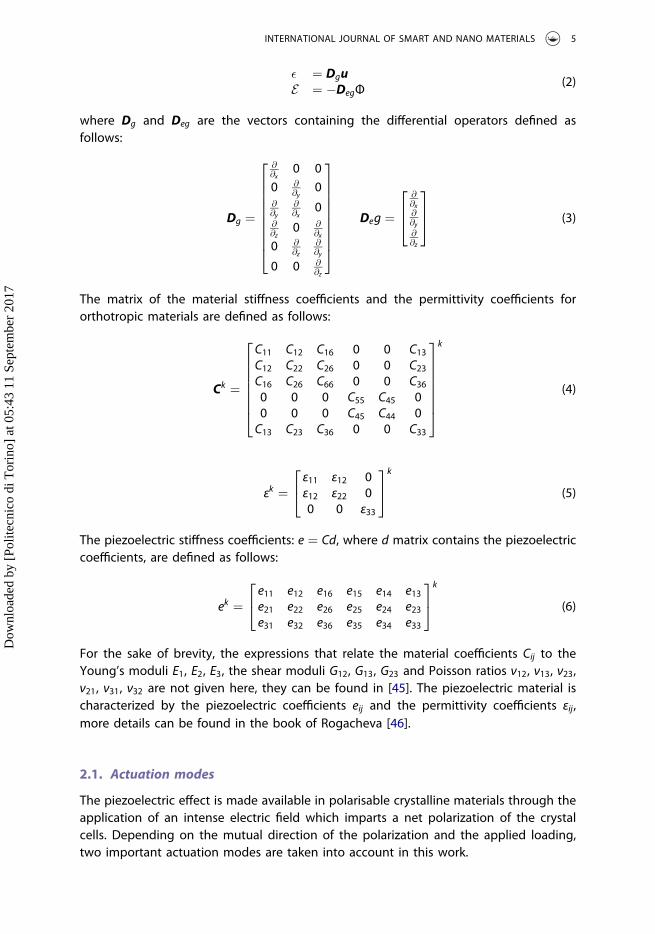
The matrix of the material stiffness coefficients and the permittivity coefficients fororthotropic materials are defined as follows:
Ck ¼
C11 C12 C16 0 0 C13C12 C22 C26 0 0 C23C16 C26 C66 0 0 C360 0 0 C55 C45 00 0 0 C45 C44 0C13 C23 C36 0 0 C33
26666664
37777775
k
(4)
εk ¼ε11 ε12 0ε12 ε22 00 0 ε33
24
35k
(5)
The piezoelectric stiffness coefficients: e ¼ Cd, where d matrix contains the piezoelectriccoefficients, are defined as follows:
ek ¼e11 e12 e16 e15 e14 e13e21 e22 e26 e25 e24 e23e31 e32 e36 e35 e34 e33
24
35k
(6)
For the sake of brevity, the expressions that relate the material coefficients Cij to theYoung’s moduli E1, E2, E3, the shear moduli G12, G13, G23 and Poisson ratios ν12, ν13, ν23,ν21, ν31, ν32 are not given here, they can be found in [45]. The piezoelectric material ischaracterized by the piezoelectric coefficients eij and the permittivity coefficients εij,more details can be found in the book of Rogacheva [46].
2.1. Actuation modes
The piezoelectric effect is made available in polarisable crystalline materials through theapplication of an intense electric field which imparts a net polarization of the crystalcells. Depending on the mutual direction of the polarization and the applied loading,two important actuation modes are taken into account in this work.
INTERNATIONAL JOURNAL OF SMART AND NANO MATERIALS 5
Dow
nloa
ded
by [
Polit
ecni
co d
i Tor
ino]
at 0
5:43
11
Sept
embe
r 20
17

2.1.1. Actuation in 3–1 modeTransverse extension mode (3–1 mode), the applied electric field is aligned with thepolarization axis, but the major deformation occurs in the transverse plane due to thethinness of the piezoelectric sheet, see Figure 2. The piezoelectric coefficients for the 3–1mode are defined as follows:
dk ¼0 0 0 d15 0 00 0 0 0 d24 0d31 d32 0 0 0 d33
24
35k
(7)
ek ¼0 0 0 e15 e14 00 0 0 e25 e24 0e31 e32 e36 0 0 e33
24
35k
(8)
2.1.2. Actuation in 1–5 modeShear mode (1–5 mode), the applied electric field is perpendicular to the polarizationdirection, and the principal mechanical effect is associated with a shear deformation, seeFigure 2. The piezoelectric coefficients for the 1–5 mode are defined as follows:
dk ¼d11 d12 0 0 0 d130 0 d26 0 0 00 0 0 d35 0 0
24
35k
(9)
ek ¼e11 e12 e16 0 0 e13e21 e22 e26 0 0 e230 0 0 e35 e34 0
2664
3775k
(10)
Figure 2. Representation of piezoelectric actuation modes taken into account. Transverse extensionmode (3–1 mode), and the shear mode (1–5 mode).
6 E. CARRERA ET AL.
Dow
nloa
ded
by [
Polit
ecni
co d
i Tor
ino]
at 0
5:43
11
Sept
embe
r 20
17
3. Refined and hierarchical plate theories for electro-mechanical problems
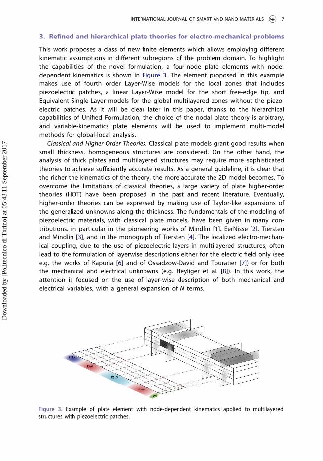
This work proposes a class of new finite elements which allows employing differentkinematic assumptions in different subregions of the problem domain. To highlightthe capabilities of the novel formulation, a four-node plate elements with node-dependent kinematics is shown in Figure 3. The element proposed in this examplemakes use of fourth order Layer-Wise models for the local zones that includespiezoelectric patches, a linear Layer-Wise model for the short free-edge tip, andEquivalent-Single-Layer models for the global multilayered zones without the piezo-electric patches. As it will be clear later in this paper, thanks to the hierarchicalcapabilities of Unified Formulation, the choice of the nodal plate theory is arbitrary,and variable-kinematics plate elements will be used to implement multi-modelmethods for global-local analysis.
Classical and Higher Order Theories. Classical plate models grant good results whensmall thickness, homogeneous structures are considered. On the other hand, theanalysis of thick plates and multilayered structures may require more sophisticatedtheories to achieve sufficiently accurate results. As a general guideline, it is clear thatthe richer the kinematics of the theory, the more accurate the 2D model becomes. Toovercome the limitations of classical theories, a large variety of plate higher-ordertheories (HOT) have been proposed in the past and recent literature. Eventually,higher-order theories can be expressed by making use of Taylor-like expansions ofthe generalized unknowns along the thickness. The fundamentals of the modeling ofpiezoelectric materials, with classical plate models, have been given in many con-tributions, in particular in the pioneering works of Mindlin [1], EerNisse [2], Tierstenand Mindlin [3], and in the monograph of Tiersten [4]. The localized electro-mechan-ical coupling, due to the use of piezoelectric layers in multilayered structures, oftenlead to the formulation of layerwise descriptions either for the electric field only (seee.g. the works of Kapuria [6] and of Ossadzow-David and Touratier [7]) or for boththe mechanical and electrical unknowns (e.g. Heyliger et al. [8]). In this work, theattention is focused on the use of layer-wise description of both mechanical andelectrical variables, with a general expansion of N terms.
Figure 3. Example of plate element with node-dependent kinematics applied to multilayeredstructures with piezoelectric patches.
INTERNATIONAL JOURNAL OF SMART AND NANO MATERIALS 7
Dow
nloa
ded
by [
Polit
ecni
co d
i Tor
ino]
at 0
5:43
11
Sept
embe
r 20
17

3.1. Unified formulation for plates
The Unified Formulation has the capability to expand each displacement variable at anydesired order. Each variable can be treated independently from the others, according tothe required accuracy. This procedure becomes extremely useful when multifield pro-blems are investigated such as thermoelastic and piezoelectric applications [27,28,47,48].According to the UF by Carrera [49–51], the displacement field and the electric potentialcan be written as follows:
ukðx; y; zÞ ¼ F0ðzÞuk0ðx; yÞ þ F1ðzÞuk1ðx; yÞ þ :::þ FNðzÞukNðx; yÞvkðx; y; zÞ ¼ F0ðzÞvk0ðx; yÞ þ F1ðzÞvk1ðx; yÞ þ :::þ FNðzÞvkNðx; yÞwkðx; y; zÞ ¼ F0ðzÞwk
0ðx; yÞ þ F1ðzÞwk1ðx; yÞ þ :::þ FNðzÞwk
Nðx; yÞΦkðx; y; zÞ ¼ F0ðzÞΦk
0ðx; yÞ þ F1ðzÞΦk1ðx; yÞ þ :::þ FNðzÞΦk
Nðx; yÞ
8>>>><>>>>:
(11)
In compact form:
ukðx; y; zÞ¼ FsðzÞuks ðx; yÞ; δukðx; y; zÞ ¼ FτðzÞδukτðx; yÞ τ; s ¼ 0; 1; :::;N
Φkðx; y; zÞ¼ FsðzÞΦks ðx; yÞ; δΦkðx; y; zÞ ¼ FτðzÞδΦk
τðx; yÞ τ; s ¼ 0; 1; :::;N(12)
where ðx; y; zÞ is the general reference system (see Figure 1), the displacement vectoru ¼ u; v;wf g and the electric potential Φ have their components expressed in thissystem. δ is the virtual variation associated to the virtual work, and k identifies thelayer. Fτ and Fs are the thickness functions depending only on z: τ and s are sum indexesand N is the number of terms of the expansion in the thickness direction assumed forthe displacements. For the sake of clarity, the superscript k is omitted in the definition ofthe Legendre polynomials.
3.2. Legendre-like polynomial expansions
The limitations, due to expressing the unknown variables in function of the midplaneposition of the shell, can be overcome in several ways. A possible solution can be foundemploying the Legendre polynomials. They permit to express the unknown variables infunction of the top and bottom position of a part of the shell thickness. In the case ofLegendre-like polynomial expansion models, the displacements and the electric poten-tial are defined as follows:
u ¼ F0 u0 þ F1 u1 þ Fr ur ¼ Fs us; s ¼ 0; 1; r ; r ¼ 2; :::;N: (13)
Φ ¼ F0 Φ0 þ F1 Φ1 þ Fr Φr ¼ Fs Φs; s ¼ 0; 1; r ; r ¼ 2; :::;N: (14)
F0 ¼ P0 þ P12
; F1 ¼ P0 � P12
; Fr ¼ Pr � Pr�2: (15)
in which Pj ¼ PjðζÞ is the Legendre polynomial of j-order defined in the ζ-domain:
�1 � ζ � 1. P0 ¼ 1, P1 ¼ ζ, P2 ¼ ð3ζ2 � 1Þ=2, P3 ¼ ð5ζ3 � 3ζÞ=2, P4 ¼ ð35ζ4 �30ζ2 þ3Þ=8.
For the Layer-Wise (LW) models, the Legendre polynomials and the relative top andbottom position are defined for each layer.
8 E. CARRERA ET AL.
Dow
nloa
ded
by [
Polit
ecni
co d
i Tor
ino]
at 0
5:43
11
Sept
embe
r 20
17

4. Finite elements with node-dependent kinematics
Thanks to Unified Formulation, FEM arrays of classical to higher-order plate theories canbe formulated in a straightforward and unified manner by employing a recursive indexnotation. By utilizing an FEM approximation, the generalized displacements of Equation(12) can be expressed as a linear combination of the shape functions to have
usðx; yÞ ¼ Njðx; yÞusj j ¼ 1; :::; ðnodes per elementÞΦsðx; yÞ ¼ Njðx; yÞΦsj j ¼ 1; :::; ðnodes per elementÞ (16)
where usj and Φsj are the vectors of the mechanical and electrical, respectively, general-ized nodal unknowns and Nj can be the usual Lagrange shape functions. j denotes asummation on the element nodes. Since the principle of virtual displacements in used inthis paper to obtain the elemental FE matrices, it is useful to introduce the finite elementapproximation of the virtual variation of the generalized displacement vector δuτ ,
δuτðx; yÞ ¼ Niðx; yÞδuτi i ¼ 1; :::; ðnodes per elementÞδΦτðx; yÞ ¼ Niðx; yÞδΦτi i ¼ 1; :::; ðnodes per elementÞ (17)
In Equation (17), δ denotes the virtual variation, whereas indexes τ and i are used insteadof s and j, respectively, for the sake of convenience.
In this work, and according to Equations (12), (16) and (17), the thickness functions Fsand Fτ , which determine the plate theory order, are independent variables and maychange for each node within the plate element. Namely, the three-dimensional displa-cement field and the related virtual variation can be expressed to address FE node-dependent plate kinematics as follows:
uðx; y; zÞ ¼ FjsðzÞNjðx; yÞusj s ¼ 0; 1; :::;Nj j ¼ 1; :::; ðnodes per elementÞΦðx; y; zÞ ¼ FjsðzÞNjðx; yÞΦsj s ¼ 0; 1; :::;Nj j ¼ 1; :::; ðnodes per elementÞδuðx; y; zÞ ¼ FiτðzÞNiðx; yÞδuτi τ ¼ 0; 1; :::;Ni i ¼ 1; :::; ðnodes per elementÞδΦðx; y; zÞ ¼ FiτðzÞNiðx; yÞδΦτi τ ¼ 0; 1; :::;Ni i ¼ 1; :::; ðnodes per elementÞ
(18)
where the subscripts τ, s, i, and j denote summation. Superscripts i and j denote nodedependency, such that for example Fiτ is the thickness expanding function and Ni is thenumber of expansion terms at node i, respectively. For the sake of clarity, the displace-ment and electric fields of a variable kinematic plate element, for example the fournnode element represented in Figure 4, is described in detail hereafter. The globaldisplacement field of the element is approximated as follows:
● Node 1 Plate Theory = HOT with N1 = 2● Node 2 Plate Theory = LW with N2 = 2● Node 3 Plate Theory = HOT with N3 = 4● Node 4 Plate Theory = HOT with N4 = 3
According to Equation (18), it is easy to verify that the displacements at a genericpoint belonging to the plate element can be expressed as given in Equation (19). In thisequation, only the displacement component along z-axis is given for simplicity reasons:
INTERNATIONAL JOURNAL OF SMART AND NANO MATERIALS 9
Dow
nloa
ded
by [
Polit
ecni
co d
i Tor
ino]
at 0
5:43
11
Sept
embe
r 20
17

wðx; y; zÞ ¼ w01 þ zw11 þ z2w21
� �N1ðx; yÞ þ 1þ ζk
2
� �w02 þ
1� ζk2
� �w12
�þ
þ 3ζ2k � 12
� 1� �
w22
N2ðx; yÞ þ w03 þ zw13 þ z2w23 þ z3w33 þ z4w43
� �
N3ðx; yÞ þ þ w04 þ zw14 þ z2w24 þ z3w34
� �N4ðx; yÞ
(19)
It is intended that, due to node-variable expansion theory order, the assembling procedureof each finite element increases in complexity with respect to classical mono-theory finiteelements. In the present FE approach, in fact, it is clear that both rectangular and squarearrays are handled and opportunely assembled for obtaining the final elemental matrices.
4.1. Fundamental nucleus of the stiffness matrix
Given Unified Formulation and FE approximation, the governing equations for the staticresponse analysis of the multi-layer plate structure can be obtained by using theprinciple of virtual displacements, which states:
�Ωk
�Akδ�Tkσk � δET
kDk dΩkdzk ¼ δLe (20)
where the term on the left-hand side represents the virtual variation of the strain energy;Ω and A are the integration domains in the plane and the thickness direction, respec-tively; ε and σ are the vector of the strain and stress components; and δLe is the virtual
Figure 4. Displacement field at the nodal level. Plate element with node-dependent kinematics.
10 E. CARRERA ET AL.
Dow
nloa
ded
by [
Polit
ecni
co d
i Tor
ino]
at 0
5:43
11
Sept
embe
r 20
17

variation of the external loadings. By substituting the constitutive equations for compo-site elastic materials Equation 1, the linear geometrical relations Equation 2 as well asEquation (18) into Equation (20), the linear algebraic system in the form of governingequations is obtained in the following matrix expression:
δukτi : Kkτsijuu uksj þ Kkτsij
uΦ Φksj ¼ Pk
uτi
δΦkτi : Kkτsij
Φu uksj þ KkτsijΦΦ Φk
sj ¼ PkΦτi
(21)
where Kτsij and Pτi are the element stiffness and load FE arrays written in the form of
fundamental nuclei. The mechanical part Kkτsijuu is a 3� 3 matrix, the coupling matrices
KkτsijuΦ , Kkτsij
Φu have dimension 3� 1 and 1� 3 respectively, and the electrical part KkτsijΦΦ is a
1� 1 matrix. The stiffness matrix nucleus Kktsijuu , and the mechanical external load vector
nucleus Pktiu are the same defined for the pure mechanical problems, reader can refers to
the work [39]. The explicit expression of the stiffness electro-mechanical couplingmatrices and the pure electric nucleus are given below with classical FEM method.The pure electric contribution is defined as follows:
KkτsijΦΦ ¼ �~εk33
ð
Ωk
NiNj dxk dykðAk
Fiτ;zFjs;z dzk � ~εk22
ð
Ωk
Ni;yNj;y dxk dykðAk
FiτFjs dzk�
�~εk12
ð
Ωk
Ni;xNj;y dxk dykðAk
FiτFjs dzk � ~εk12
ð
Ωk
Ni;yNj;x dxk dykðAk
FiτFjs dzk�
�~εk11
ð
Ωk
Ni;xNj;x dxk dykðAk
FiτFjs dzk
The stiffness electro-mechanical coupling matrices KktsijuΦ and Kktsij
Φu are defined asfollows:
KktsijuΦ ¼
KuΦx
KuΦy
KuΦz
24
35kτsij
(22)
KktsijΦu ¼ KΦux KΦuy KΦuz
� �kτsij(23)
4.1.1. Actuation in 3–1 mode
KkτsijuΦx
¼ ~ek25
ð
Ωk
NiNj;y dxk dyk
ðAk
F iτ;zF
js dz
k þ ~ek15
ð
Ωk
NiNj;x dxk dyk
ðAk
F iτ;zF
js dz
kþ
þ~ek36
ð
Ωk
Ni;yNj dxk dyk
ðAk
F iτF
js;z dz
k þ ~ek31
ð
Ωk
Ni;xNj dxk dyk
ðAk
F iτF
js;z dz
k
INTERNATIONAL JOURNAL OF SMART AND NANO MATERIALS 11
Dow
nloa
ded
by [
Polit
ecni
co d
i Tor
ino]
at 0
5:43
11
Sept
embe
r 20
17

KkτsijuΦy
¼ ~ek24
ð
Ωk
NiNj;y dxk dykðAk
Fiτ;zFjs dzk þ ~ek14
ð
Ωk
NiNj;x dxk dykðAk
Fiτ;zFjs dzkþ
þ~ek32
ð
Ωk
Ni;yNj dxk dykðAk
FiτFjs;z dzk þ ~ek36
ð
Ωk
Ni;xNj dxk dykðAk
FiτFjs;z dzk
KkτsijuΦz
¼ ~ek33
ð
Ωk
NiNj dxk dykðAk
Fiτ;zFjs;z dzk þ ~ek24
ð
Ωk
Ni;yNj;y dxk dykðAk
FiτFjs dzkþ
þ~ek25
ð
Ωk
Ni;xNj;y dxk dykðAk
FiτFjs dzk þ ~ek14
ð
Ωk
Ni;yNj;x dxk dykðAk
FiτFjs dzkþ
þ~ek15
ð
Ωk
Ni;xNj;x dxk dykðAk
FiτFjs dzk
KkτsijΦux
¼ ~ek36
ð
Ωk
NiNj;y dxk dykðAk
Fiτ;zFjs dzk þ ~ek31
ð
Ωk
NiNj;x dxk dykðAk
Fiτ;zFjs dzkþ
þ~ek25
ð
Ωk
Ni;yNj dxk dykðAk
FiτFjs;z dzk þ ~ek15
ð
Ωk
Ni;xNj dxk dykðAk
FiτFjs;z dzk
KkτsijΦuy
¼ ~ek32
ð
Ωk
NiNj;y dxk dykðAk
Fiτ;zFjs dzk þ ~ek36
ð
Ωk
NiNj;x dxk dykðAk
Fiτ;zFjs dzkþ
þ~ek24
ð
Ωk
Ni;yNj dxk dykðAk
FiτFjs;z dzk þ ~ek14
ð
Ωk
Ni;xNj dxk dykðAk
FiτFjs;z dzk
KkτsijΦuz
¼ ~ek33
ð
Ωk
NiNj dxk dykðAk
Fiτ;zFjs;z dzk þ ~ek24
ð
Ωk
Ni;yNj;y dxk dykðAk
FiτFjs dzkþ
þ~ek14
ð
Ωk
Ni;xNj;y dxk dykðAk
FiτFjs dzk þ ~ek25
ð
Ωk
Ni;yNj;x dxk dykðAk
FiτFjs dzkþ
þ~ek15
ð
Ωk
Ni;xNj;x dxk dykðAk
FiτFjs dzk
4.1.2. Actuation in 1–5 mode
KkτsijuΦx
¼ ~ek35
ð
Ωk
NiNj dxk dykðAk
Fiτ;zFjs;z dzk þ ~ek26
ð
Ωk
Ni;yNj;y dxk dykðAk
FiτFjs dzkþ
þ~ek21
ð
Ωk
Ni;xNj;y dxk dykðAk
FiτFjs dzk þ ~ek16
ð
Ωk
Ni;yNj;x dxk dykðAk
FiτFjs dzkþ
þ~ek11
ð
Ωk
Ni;xNj;x dxk dykðAk
FiτFjs dzk
12 E. CARRERA ET AL.
Dow
nloa
ded
by [
Polit
ecni
co d
i Tor
ino]
at 0
5:43
11
Sept
embe
r 20
17

KkτsijuΦy
¼ ~ek34
ð
Ωk
NiNj dxk dykðAk
Fiτ;zFjs;z dzk þ ~ek22
ð
Ωk
Ni;yNj;y dxk dykðAk
FiτFjs dzkþ
þ~ek26
ð
Ωk
Ni;xNj;y dxk dykðAk
FiτFjs dzk þ ~ek12
ð
Ωk
Ni;yNj;x dxk dykðAk
FiτFjs dzkþ
þ~ek16
ð
Ωk
Ni;xNj;x dxk dykðAk
FiτFjs dzk
KkτsijuΦz
¼ ~ek23
ð
Ωk
NiNj;y dxk dykðAk
Fiτ;zFjs dzk þ ~ek13
ð
Ωk
NiNj;x dxk dykðAk
Fiτ;zFjs dzkþ
þ~ek34
ð
Ωk
Ni;yNj dxk dykðAk
FiτFjs;z dzk þ ~ek35
ð
Ωk
Ni;xNj dxk dykðAk
FiτFjs;z dzk
KkτsijΦux
¼ ~ek35
ð
Ωk
NiNj dxk dykðAk
Fiτ;zFjs;z dzk þ ~ek26
ð
Ωk
Ni;yNj;y dxk dykðAk
FiτFjs dzkþ
þ~ek16
ð
Ωk
Ni;xNj;y dxk dykðAk
FiτFjs dzk þ ~ek21
ð
Ωk
Ni;yNj;x dxk dykðAk
FiτFjs dzkþ
þ~ek11
ð
Ωk
Ni;xNj;x dxk dykðAk
FiτFjs dzk
KkτsijΦuy
¼ ~ek34
ð
Ωk
NiNj dxk dykðAk
Fiτ;zFjs;z dzk þ ~ek22
ð
Ωk
Ni;yNj;y dxk dykðAk
FiτFjs dzkþ
þ~ek12
ð
Ωk
Ni;xNj;y dxk dykðAk
FiτFjs dzk þ ~ek26
ð
Ωk
Ni;yNj;x dxk dykðAk
FiτFjs dzkþ
þ~ek16
ð
Ωk
Ni;xNj;x dxk dykðAk
FiτFjs dzk
KkτsijΦuz
¼ ~ek34
ð
Ωk
NiNj;y dxk dykðAk
Fiτ;zFjs dzk þ ~ek35
ð
Ωk
NiNj;x dxk dykðAk
Fiτ;zFjs dzkþ
þ~ek23
ð
Ωk
Ni;yNj dxk dykðAk
FiτFjs;z dzk þ ~ek13
ð
Ωk
Ni;xNj dxk dykðAk
FiτFjs;z dzk
where comma denote partial derivatives respect to the spatial directions.The fundamental nucleus as given above is the basic building block for the construc-
tion of the element stiffness matrix of classical, refined and variable-kinematic theories.In fact, given these nine components, element stiffness matrices of arbitrary platemodels can be obtained in an automatic manner by expanding the fundamental nucleusversus the indexes τ, s, i, and j: In the development of ESL theories as in the case of thispaper, the fundamental nucleus of the stiffness matrix is evaluated at the layer level andthen assembled as shown in Figure 5. This figure, in particular, illustrates the expansion
INTERNATIONAL JOURNAL OF SMART AND NANO MATERIALS 13
Dow
nloa
ded
by [
Polit
ecni
co d
i Tor
ino]
at 0
5:43
11
Sept
embe
r 20
17

of the fundamental nucleus in the case of a 9-node Lagrange finite element with node-by-node variable kinematics, as in the case of this paper. It must be added that, in thiswork, an MITC technique is used to overcome the shear locking phenomenon, see [48].However, for more details about the explicit formulation of the Unified Formulationfundamental nuclei, interested readers are referred to the recent book by Carreraet al. [52].
5. Numerical results
Some problems have been considered to assess the capabilities of the proposed vari-able-kinematics plate elements and related global/local analysis. These analysis casescomprise both composite and sandwich laminated plate structures with differentboundary conditions and loadings. Whenever possible, the proposed multi-theory mod-els are compared to single-theory refined elements. According to Unified Formulationterminology, the latter models are referred to as LWN, where LW stands for Layer-Wisemodels (LW), and N is the theory approximation order. Eventually, 3D exact or finiteelement models, and Arlequin multi-model solutions are used for comparisons and, inthose cases, the opportune notation is mentioned case by case. If a Navier-type closedform solution is employed instead of FEM, the subscript ðaÞ is used. On the contrary, forthe sake of clarity, multi-model theories are opportunely described for each numericalcase considered.
5.1. Simply-supported cross-ply composite plates with piezoelectric skins
To assess this new finite element, a four-layer cross-ply square plate with a cross-ply Gr/Ep composite core ½0�/90�� and PZT-4 piezoelectric external skins is analyzed, seeFigure 6. The square plate has the following geometrical data: a ¼ b ¼ 4:0, andhtot ¼ 1:0. In respect to the total thickness, a single piezoelectric skin is thick
Figure 5. Assembling scheme of a 9-node finite element with node-dependent kinematics.Highlights of the influence of the cubic term of a 3rd order expansion model in the FE stiffness.
14 E. CARRERA ET AL.
Dow
nloa
ded
by [
Polit
ecni
co d
i Tor
ino]
at 0
5:43
11
Sept
embe
r 20
17

hp ¼ 0:1htot , while the single core layer is thick hc ¼ 0:4htot . The static analysis of theplate structure is evaluated in sensor and actuator configuration.
For the sensor case, a bi-sinusoidal transverse normal pressure is applied to the topsurface of the plate:
p x; y; ztop� � ¼ poz sinðmπx=aÞsinðnπy=bÞ (24)
with amplitude poz ¼ 1 and wave numbers m ¼ 1, n ¼ 1. The potential at top andbottom position is imposed Φt ¼ Φb ¼ 0. For the actuator case, a bi-sinusoidal electricpotential is imposed at top surface:
Φ x; y; ztop� � ¼ ϕo
z sinðmπx=aÞsinðnπy=bÞ (25)
with amplitude ϕoz ¼ 1 and wave numbers m ¼ 1, n ¼ 1. The potential at bottom
position is imposed Φb ¼ 0. No mechanical load is applied. The material properties ofthe plate are given in Table 1.
The plate has simply-supported boundary conditions. Due to the symmetry of boththe geometry and the load, a quarter of the plate is analyzed and the followingsymmetry and boundary conditions (simply-supported) are applied:
Boundary Symmetryusðx; 0Þ ¼ 0 wsðx; 0Þ ¼ 0 usða=2; yÞ ¼ 0vsð0; yÞ ¼ 0 wsð0; yÞ ¼ 0 vsðx; b=2Þ ¼ 0Φsðx; 0Þ ¼ 0 Φsð0; yÞ ¼ 0
(26)
The boundary condition of the electric potential is taken into account to compare theresults with the analytical solution, see [9], where the electric potential has the followingNavier-type assumptions Φ ¼ Φ̂sinðmπx=aÞsinðnπy=bÞ.
To compare the results with other solutions present in literature [38](Arlequinmethod), the mid-plane domain of the plane structure was subdivided into two zonesalong the axes x and y, as shown in Figure 7, and multi-theory models CaseA, CaseB andCaseC are depicted on the FE discretization of a quarter of the plate. The FE mesh on aquarter plate is 10� 10 elements, the accounted mesh is the same used in the reference
Figure 6. Reference system of the composite plate with piezoelectric skins.
INTERNATIONAL JOURNAL OF SMART AND NANO MATERIALS 15
Dow
nloa
ded
by [
Polit
ecni
co d
i Tor
ino]
at 0
5:43
11
Sept
embe
r 20
17

Table1.
Materiald
ataformultilayered
plate.
MechanicalP
roperties
E 11½GP
a�E 2
2½GP
a�E 3
3½GP
a�ν 1
2½�
�ν 1
3½�
�ν 2
3½�
�G12½GP
a�G13½GP
a�G23½GP
a�Gr=EP
132.38
10.756
10.756
0.24
0.24
0.49
5.6537
5.6537
3.606
PZT�4
81.3
81.3
64.5
0.329
0.432
0.432
30.6
25.6
25.6
ElectricalProp
erties e 15½C=
m2 �
e 24½C=
m2 �
e 31½C=
m2�
e 32½C=
m2�
e 33½C=
m2�
~ ε 11=ε 0½�
�~ ε 2
2=ε 0½�
�~ ε 3
3=ε 0½�
�ε 0½C=
Vm�
Gr=EP
00
00
03.5
3.0
3.0
8:85
�10�
12
PZT�4
12.72
12.72
−5.20
−5.20
15.08
1475
1475
1300
8:85
�10�
12
16 E. CARRERA ET AL.
Dow
nloa
ded
by [
Polit
ecni
co d
i Tor
ino]
at 0
5:43
11
Sept
embe
r 20
17

solutions [38]; the difference is that, in the reference solutions, it is used a four-nodeelement and a Reissner Mixed Variational Theorem applied to the transverse electricdisplacement Dz (RMVT � Dz), the transverse electric displacement is a priori modelledwith the mechanical displacements. It has to be noticed that the mesh discretization ofthe present multi-models CaseA and CaseC is the same of the reference Arlequin
solutions named ðLW1� LWM3ÞA and ðLW2� LWM3ÞC .Some results of the transverse mechanical displacement w, in-plane stress σxx ,
transverse shear stress σxz , transverse normal stress σzz, electric potential Φ, and trans-vserse electric displacement Dz evaluated along the plate thickness are given in tabularform, see Tables 2 and 3, for the sensor case and the actuator case respectively. Mono-theory models are compared with those from the present multi-model approach,furthermore, the exact 3D solutions provided by Heyliger [53], the analytical solutionwith layer-wise mono-models [9], and the multi-model solutions via the Arlequinmethod [38] are given. For the transverse shear and normal stresses, the evaluationpoint is located between the composite layers, their results are given for the upper layer
Figure 7. Mesh zones of the composite plate with piezoelectric skins and graphical representation ofthe multi-theory models, based on layer-wise models.
INTERNATIONAL JOURNAL OF SMART AND NANO MATERIALS 17
Dow
nloa
ded
by [
Polit
ecni
co d
i Tor
ino]
at 0
5:43
11
Sept
embe
r 20
17

with upscript þ and for the lower layer with upscript �. It is clear for both sensor andactuator cases that at least a second order expansion order is needed to get good resultsfor all the considered variables.
Some results are given in terms of transverse displacement w, transverse shear stressσxz and electric transverse displacement Dz along the plate thickness. For the transversedisplacement w, in sensor case configuration, the differences between single and multi-models are negligible, see Figure 8(a). On the contrary for the actuator case, see Figure 8(b), remarkable differences are present between LW4 and LW1 single-model solutions;extending the comparison to the multi-models, it is clear that a more refined expansionis needed in the center plate where the load is higher, see CaseA and CaseC, differentlyCaseB shows an accuracy very close to LW1 single-model.
The transverse shear stress σxz is represented in Figure 9(a) for the actuator config-uration. The stress is evaluated in its maximum shear stress value point ðx; yÞ ¼ ð0; b=2Þ.The mono-model LW4 is able to predict the correct behavior as the 3DExact referencesolution [53]. The higher-order multi-models CaseA and CaseC are not sufficient todepict the good representation of the shear stress. Differently CaseB shows a goodaccuracy solution due to the higher-order representation in the evaluation zone of theshear stress.
Regarding the electric transverse displacement Dz, represented in Figure 9(b) for thesensor configuration, it is evaluated in the center plate. The mono-model LW4 canpredict the correct behavior as the 3DExact reference solution [53]. In this case, the
Table 2. Composite four-layered plate with piezoelectric skins. Transverse displacement�w ¼ ð1011Þ � wða=2; b=2; 0Þ, in-plane stress �σxx ¼ σxxða=2; b=2;þh=2Þ, transverse shear stress�σxz ¼ σxzð0; b=2; 0Þ, transverse normal stress �σzz ¼ ð10Þ � σzzða=2; b=2; 0Þ, electric potential�Φ ¼ ð102Þ � Φða=2; b=2; 0Þ, and transverse electric displacement �Dz ¼ ð1010Þ � Dzða=2;b=2;þh=2Þ by various single- and multi-theory models. Sensor Case.
�w �σxx �σxz �σzz �Φ �Dz DOFs
Reference solutions3DExact[53] 30.027 6.5643 – 4.9831 0.611 0.1606LW4a[9] 30.029 6.5642 0.6872 – 0.6108 0.161LW1a[9] 29.852 6.9995 – – 0.6030 −-0.880ðLW1� LWM3ÞA[38] 29.91 – – 4:888þ 0.555 −-0.0252
5:159�
ðLW2� LWM3ÞC [38] 29.72 – – 4:871þ – 0.15335:147�
Present single- and multi-theory modelsLW4 30.029 6.5739 0:6906þ 4:9844þ 0.6111 0.1321 29,988
0:6886� 4:9812�LW3 30.029 6.5749 0:6866þ 4:8882þ 0.6110 0.1348 22,932
0:6886� 5:0648�LW2 29.981 6.5690 0:8162þ 5:2397þ 0.6090 0.1489 15,876
0:7058� 4:8336�LW1 29.851 7.0132 0:7099þ 5:7912þ 0.6032 −-0.8948 8820
0:6791� 3:9877�CaseA 29.932 6.5694 0:7100þ 4:8889þ 0.6100 0.1365 12,692
0:6798� 5:0506�CaseB 29.926 7.0033 0:6816þ 5:7928þ 0.6025 −-0.8936 19,060
0:6863� 3:9850�CaseC 29.999 6.5852 0:8168þ 4:8965þ 0.6108 0.1353 17,812
0:7057� 5:0601�
18 E. CARRERA ET AL.
Dow
nloa
ded
by [
Polit
ecni
co d
i Tor
ino]
at 0
5:43
11
Sept
embe
r 20
17

multi-models CaseA and CaseC, differently from CaseB, are able to get a good accuracysolution due to the higher-order representation in the center plate zone.
Table 3. Composite four-layered plate with piezoelectric skins. Transverse displacement�w ¼ ð1011Þ � wða=2; b=2; 0Þ, in-plane stress �σxx ¼ σxxða=2; b=2;þh=2Þ, transverse shear stress�σxz ¼ ð10Þ � σxzð0; b=2; 0Þ, transverse normal stress �σzz ¼ ð103Þ � σzzða=2; b=2; 0Þ, electric poten-tial �Φ ¼ Φða=2; b=2; 0Þ, and transverse electric displacement �Dz ¼ ð109Þ � Dzða=2; b=2;þh=2Þ byvarious single- and multi-theory models. Actuator Case.
�w �σxx �σxz �σzz �Φ �Dz DOFs
Reference solutions3DExact[53] −1.471 1.1181 −0.2387 −14.612 0.4476 –LW4a[9] −1.4707 1.1180 −0.239 – 0.4477 −2.4184LW1a[9] −1.5962 3.3433 – – 0.4468 −1.3814ðLW1� LWM3ÞA[38] −1.420 1.119 – – – –
ðLW2� LWM3ÞC [38] −1.410 – – – – –
Present single- and multi-theory modelsLW4 −1.4707 1.1248 � 0:2411þ � 14:732þ 0.4477 −2.4186 29,988
� 0:2391� � 14:660�LW3 −1.4707 1.1261 � 0:2270þ � 13:541þ 0.4477 −2.4183 22,932
� 0:2394� � 15:343�LW2 −1.4662 1.1311 � 0:3592þ � 20:604þ 0.4477 −2.4167 15,876
� 0:2505� � 15:978�LW1 −1.5962 3.3531 � 0:0293þ 14:188þ 0.4468 −1.3816 8820
� 0:2980� � 21:879�CaseA −1.4729 1.1315 � 0:0302þ � 12:729þ 0.4479 −2.4183 12,692
� 0:2979� � 14:223�CaseB −1.5916 3.3590 � 0:2210þ � 14:026þ 0.4467 −1.3818 19,060
� 0:2385� � 21:913�CaseC −1.4679 1.1250 � 0:3599þ � 13:641þ 0.4477 −2.4183 17,812
� 0:2504� � 15:318�
28
28.5
29
29.5
30
30.5
31
31.5
32
-0.5 -0.4 -0.3 -0.2 -0.1 0 0.1 0.2 0.3 0.4 0.5
w-
z
LW4
LW1
Case A
Case B
Case C
(a) Sensor Case
-1.75
-1.7
-1.65
-1.6
-1.55
-1.5
-1.45
-1.4
-1.35
-0.5 -0.4 -0.3 -0.2 -0.1 0 0.1 0.2 0.3 0.4 0.5
w-
z
LW4
LW1
Case A
Case B
Case C
(b) Actuator Case
Figure 8. Composite plate with piezoelectric skins. Transverse displacement�wðx; yÞ ¼ 1011 � wða=2; b=2Þ. Sensor and Actuator Cases. Single and Multi-theory models.
INTERNATIONAL JOURNAL OF SMART AND NANO MATERIALS 19
Dow
nloa
ded
by [
Polit
ecni
co d
i Tor
ino]
at 0
5:43
11
Sept
embe
r 20
17

Results in terms of in-plane stress �σxxðy; zÞ ¼ σxx , and transverse electric displacement�Dz ¼ ð1010Þ � Dz along the in-plane x axis are represented in Figure 10(a,b) respectively.For both the depicted variables, the multi-model CaseC is able to reproduce the correct
-0.04
-0.02
0
0.02
0.04
0.06
0.08
0.1
-0.5 -0.4 -0.3 -0.2 -0.1 0 0.1 0.2 0.3 0.4 0.5
σ-xz
z
3D Exact
LW4
LW1
Case A
Case B
Case C
(a) σ̄xz, Actuator Case
-1
-0.8
-0.6
-0.4
-0.2
0
0.2
0.4
0.6
0.8
1
1.2
-0.5 -0.4 -0.3 -0.2 -0.1 0 0.1 0.2 0.3 0.4 0.5
D-z
z
3D Exact
LW4
LW1
Case A
Case B
Case C
(b) D̄z, Sensor Case
Figure 9. Composite plate with piezoelectric skins. Transverse shear stress �σxzðx; yÞ ¼ ð10Þ �σxzð0; b=2Þ for the Actuator Case, and transverse electric displacement �Dzðx; yÞ ¼ ð1010Þ �Dzða=2; b=2Þ for the Sensor Case. Single and Multi-theory models.
0
0.5
1
1.5
2
2.5
3
3.5
0 0.5 1 1.5 2
σ-xx
x
LW4
LW1
Case A
Case B
Case C
-1
-0.8
-0.6
-0.4
-0.2
0
0.2
0 0.5 1 1.5 2
D-z
x
LW4
LW1
Case A
Case B
Case C
(b) D̄z, Sensor Case(a) σxx, Actuator Case¯
Figure 10. Composite plate with piezoelectric skins. In-plane stress �σxxðy; zÞ ¼ σxxðb=2;þh=2Þ forthe Actuator Case, and transverse electric displacement �Dzðy; zÞ ¼ ð1010Þ � Dzðb=2;þh=2Þ for theSensor Case, along the in-plane direction X, the axis X is expressed in ½mm�. Single and Multi-theorymodels.
20 E. CARRERA ET AL.
Dow
nloa
ded
by [
Polit
ecni
co d
i Tor
ino]
at 0
5:43
11
Sept
embe
r 20
17
behavior along the X axis as the reference solution LW4. The linear single model LW1and multi-models CaseA and CaseB show an incorrect solution in the zone where alinear approximation is used. In the transition elements small oscillations are present,these oscillations are due to the coarse mesh, if the mesh is more refined the oscillationstend to fade.
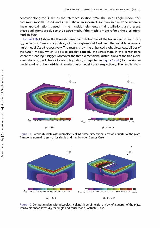
Figure 11(a,b) show the three-dimensional distributions of the transverse normal stressσzz , in Sensor Case configuration, of the single-model LW4 and the variable kinematicmulti-model CaseA respectively. The results show the enhanced global/local capabilities ofthe CaseA model, which is able to predict correctly the stress state in the center zonewhere the loading is bigger. Moreover the three-dimensional distributions of the transverseshear stress σxz, in Actuator Case configuration, is depicted in Figure 12(a,b) for the single-model LW4 and the variable kinematic multi-model CaseB respectively. The results show
(a) LW4 (b) Case A
Figure 11. Composite plate with piezoelectric skins, three-dimensional view of a quarter of the plate.Transverse normal stress σzz for single and multi-model. Sensor Case.
(a) LW4 (b) Case B
Figure 12. Composite plate with piezoelectric skins, three-dimensional view of a quarter of the plate.Transverse shear stress σxz for single and multi-model. Actuator Case.
INTERNATIONAL JOURNAL OF SMART AND NANO MATERIALS 21
Dow
nloa
ded
by [
Polit
ecni
co d
i Tor
ino]
at 0
5:43
11
Sept
embe
r 20
17

the enhanced global/local capabilities of the CaseB model, it represents accurately themaximum shear stress in boundary zone of the plate structure.
5.2. Sandwich cantilever plate shear-actuated in mode-15
A cantilever sandiwch plate is analysed as second example and it is shown in Figure 13. Thegeometrical dimensions are: a ¼ 100 mm, b ¼ 20 mm, htotal ¼ 18 mm. The upper andlower layers are made of Aluminum with the following mechanical properties:E ¼ 70:3GPa, ν ¼ 0:345, ε ¼ 30:975� 10�12 F=m; each aluminum layer is thickhAl ¼ 8 mm. The central layer is thick hc ¼ 2 mm, it is made of Foam, with the followingproperties: E ¼ 35:3MPa, ν ¼ 0:38, ε ¼ 30:975� 10�12 F=m; a small PZT-5H piezoelectricpatches is introduced in the foam layer with dimension: ap ¼ 10 mm, bp ¼ 20 mm,hp ¼ 2 mm, the PZT-5H material has the following properties: C11 ¼ C22 ¼ C33 ¼ 126GPa,
C23 ¼ 79:5GPa, C12 ¼ C13 ¼ 84:1GPa, C44 ¼ C55 ¼ C66 ¼ 23GPa, e11 ¼ 23:3C=m2,e12 ¼ e13 ¼ �6:5C=m2, e26 ¼ e35 ¼ 17C=m2, ε11 ¼ 1:3� 10�8 F=m,ε22 ¼ ε33 ¼ 1:503� 10�8 F=m. The material PZT-5H is polarized in the x-direction, or inmode� 15. The structure is loaded at the upper and lower surfaces of the piezoelectricpatch with a constant uniform electric potential equal to Φt=b ¼ �10:0V:
First, a convergence study on a single-theory plate model was performed. As far as anLW4 model is concerned and as shown in Table 4, a non-uniform mesh grid of 56� 8elements, see Figure 14 is enough to ensure convergent results. This structural problemhas become popular and it is a good benchmark problem for its selectivity. The presentplate element model is compared with various solutions from the literature, including
Figure 13. Reference system of the sandwich plate with piezoelectric patch, and three-dimensionalrepresentation of the deformation under the electric load.
22 E. CARRERA ET AL.
Dow
nloa
ded
by [
Polit
ecni
co d
i Tor
ino]
at 0
5:43
11
Sept
embe
r 20
17

those of Zhang and Sun [54,55], Benjeddou et al. [56]. Some results are given varying theactuator position along the x-axis, the deflection at the free edge is investigated for eachposition of the piezoelectric patch, see Figure 15, and compared with the literaturesolutions [54,56], here named Sun & Zhang, and Benjeddou et al., respectively.
Various node-variable kinematic models have been used to perform the global/localanalysis of the proposed plate structure, with the center of the piezoelectric patch fixedat d ¼ 85 mm. The mid-plane domain of the plate structure was subdivided into higher-order and lower-order zones along the axes x and y and they are depicted in Figure 16.The mesh discretization of the present multi-models is arbitrary. The idea behind the
Table 4. Convergence study versus the number of elements of the LW4 single-theory model of thesandwich cantilever plate. Transverse displacement w ¼ 108 � wða; b=2;þh=2Þ, electric potentialΦ ¼ Φðd; b=2;�h=2Þ, in-plane principal stress σxx ¼ σxxðd; b=2;�h=2Þ, transverse shear stressσxz ¼ σxzðd; b=2; 0Þ, with the center of the piezoelectric patch placed at d ¼ 85 mm.
w Φ σxx σxz DOFs
Mesh8� 2zone1 zone2 zone3 zone4 6.7194 0.5852 983.17 −1220.7 44202� 2 2� 2 2� 2 2� 2
Mesh16� 4zone1 zone2 zone3 zone4 6.7531 0.1404 1023.7 −959.22 15,4444� 4 4� 4 4� 4 4� 4
Mesh32� 8zone1 zone2 zone3 zone4 6.7673 0.0257 944.61 −967.35 57,4608� 8 8� 8 8� 8 8� 8
Mesh64� 16zone1 zone2 zone3 zone4 6.7738 0.0097 956.82 −981.90 221,36416� 16 16� 16 16� 16 16� 16
Mesh56� 8zone1 zone2 zone3 zone4 6.7661 0.0172 957.65 −983.45 99,8928� 8 16� 8 16� 8 16� 8
Figure 14. Mesh zone subdivisions of the sandwich plate with piezoelectric patch, for the conver-gence study.
INTERNATIONAL JOURNAL OF SMART AND NANO MATERIALS 23
Dow
nloa
ded
by [
Polit
ecni
co d
i Tor
ino]
at 0
5:43
11
Sept
embe
r 20
17

discretization consists into the study of the effect of the transition zones position respectwith to the variables evaluation points. Some results of the transverse mechanicaldisplacement w, in-plane stress σxx , transverse shear stress σxz , transverse normal stressσzz, electric potential Φ, and transverse electric displacement Dz evaluated along theplate thickness are given in tabular form, see Table 5. Mono-theory models are com-pared with those from the present multi-model approach, furthermore the FEM 3Dsolution provided by 3DAbaqus C3D20RE element is given.
Some results in terms of transverse displacement w, and electric potential Φ alongthe thickness are represented in Figure 17(a,b), furthermore three-dimensional viewof the electric potential Φ is given in Figure 18(a,b). Some more comments can bemade:
● The through-the-thickness distribution of the transverse displacement w at the freetip, as shown in Figure 17(a), is correctly predicted by higher-order single-modelsLW3 and LW4. The same accuracy is reached by the Case A multi-model and littlelosses in accuracy are present in the Case B and Case C multi-models.
● The behavior of the electric potential Φ along the thickness, depicted in Figure 16,is well described for every single and multi-models. Furthermore the three-dimen-sional view of the electric potential Φ, on deformed structure, is given by the finiteelement 3DAbaqus C3D20RE, see Figure 18(a), and the present mono-model LW4,see Figure 18(b). It has noticeable that the electric potential calculated by thecommercial 3DAbaqus C3D20RE finite element does not tend to zero at the topand bottom positions of the inserted patch zone, differently the present LW4model well describe the electric potential behavior without imposing any boundary
Figure 15. Sandwich plate with piezoelectric patch, tip transverse displacement wðx; y; zÞ ¼ 108 �wða; b=2;þh=2Þ for several position of the piezoelectric patch along the x-axis direction.
24 E. CARRERA ET AL.
Dow
nloa
ded
by [
Polit
ecni
co d
i Tor
ino]
at 0
5:43
11
Sept
embe
r 20
17

Figure 16. Graphical representation of the multi-theory models, based on layer-wise models, of thesandwich plate with piezoelectric patch, for the node-variable kinematic study.
Table 5. Single-theory and multi-theory models of the sandwich cantilever plate. Transversedisplacement w ¼ 108 � wða; b=2;þh=2Þ, electric potential Φ ¼ Φðd; b=2;�h=2Þ, in-plane princi-pal stress σxx ¼ σxxðd; b=2;�h=2Þ, transverse shear stress σxz ¼ σxzðd; b=2; 0Þ, transverse normalstress σzz ¼ σzzðd; b=2;�h=2Þ, transverse electric displacement Dz ¼ 104 �Dzðd; b=2; 0Þ, with thecenter of the piezoelectric patch placed at d ¼ 85 mm.
w σxx σxz σzz Φ Dz DOFs
3D Abaqus C3D20RE 6.7775 939.50 −1001.1 −3.7539 6.3489 2.7525 627,028LW4 6.7661 957.65 −983.45 36.319 0.0172 2.7523 99,892LW3 6.7716 819.22 −941.32 −262.36 0.0187 2.7526 76,840LW2 6.7957 1163.2 −878.64 354.78 0.0208 2.7530 53,788LW1 6.6923 684.02 −969.41 465.55 0.0443 2.7524 30,736CaseA 6.7660 958.91 −984.12 36.388 −0.0116 2.7523 86,836CaseB 6.7914 901.61 −858.59 −18.913 −0.0112 2.7532 77,044CaseC 6.7738 915.53 −949.66 36.314 −0.0094 2.7526 67,252
INTERNATIONAL JOURNAL OF SMART AND NANO MATERIALS 25
Dow
nloa
ded
by [
Polit
ecni
co d
i Tor
ino]
at 0
5:43
11
Sept
embe
r 20
17

conditions at the top and bottom positions.Furthermore, some results in terms of mechanical stresses are given for the in-planestress σxx in Figure 19(a), transverse normal stress σzz in Figure 19(b), and transverseshear stress σxz in Figure 20(a,b) and 21(a,b). Some more comments can be made:
● The through-the-thickness distribution of the in-plane stress σxx , as shown inFigure 19(a), is correctly predicted by higher-order single-models LW3 and LW4.The same accuracy is reached by all the considered multi-models, where theevaluation point is described by the LW4 theory. It has to be noticed that theCaseB show a little loss in accuracy due to the short distance of the evaluationpoint from the transition elements.
6.45
6.5
6.55
6.6
6.65
6.7
6.75
6.8
-0.5 -0.4 -0.3 -0.2 -0.1 0 0.1 0.2 0.3 0.4 0.5
w-
z
LW4
LW3
LW2
LW1
Case A
Case B
Case C
Abaqus C3D20RE
(a) w
-10
-8
-6
-4
-2
0
2
4
6
8
10
-0.5 -0.4 -0.3 -0.2 -0.1 0 0.1 0.2 0.3 0.4 0.5
Φ-
z
LW4
LW3
LW2
LW1
Case A
Case B
Case C
Abaqus C3D20RE
(b) Φ
Figure 17. Sandwich cantilever plate, transverse displacement wðx; yÞ ¼ 108 � wða; b=2Þ, andelectric potential Φðx; yÞ ¼ Φðd; b=2Þ. Single and Multi-theory models.
EPOT
−1.000e+01−9.167e+00−8.333e+00−7.500e+00−6.667e+00−5.833e+00−5.000e+00−4.167e+00−3.333e+00−2.500e+00−1.667e+00−8.333e−01−1.192e−07+8.333e−01+1.667e+00+2.500e+00+3.333e+00+4.167e+00+5.000e+00+5.833e+00+6.667e+00+7.500e+00+8.333e+00+9.167e+00+1.000e+01
Step: Step−1Increment 1: Step Time = 1.000Primary Var: EPOTDeformed Var: U Deformation Scale Factor: +2.000e+05
ODB: Job−1.odb Abaqus/Standard 6.14−1 Mon Apr 24 22:03:47 CEST 2017
XY
Z
(a) 3D Abaqus C3D20RE (b) LW4
Figure 18. Sandwich cantilever plate, three-dimensional view of the electric potential Φ, ondeformed structure. 3D Abaqus C3D20RE and mono-model LW4.
26 E. CARRERA ET AL.
Dow
nloa
ded
by [
Polit
ecni
co d
i Tor
ino]
at 0
5:43
11
Sept
embe
r 20
17

● The transverse normal stress σzz , as shown in Figure 19(b), is well described by theLW4 single-model. The same accuracy is reached by all the considered multi-models, where the evaluation point is described by the LW4 theory. As mentionedfor the in-plane stress σxx , the CaseB show a little loss in accuracy due to the shortdistance of the evaluation point from the transition elements.
● The three-dimensional view of the transverse shear stress σxz, on undeformedstructure, is given by the finite element 3DAbaqus C3D20RE in Figure 20(a), bythe present mono-model LW4 in Figure 20(b), and by multi-model Case C inFigure 21(a), in which it is possible to notice the differences, at the clampedboundaries and at the transition elements close to the patch zone, respect to
-1500
-1000
-500
0
500
1000
1500
-0.5 -0.4 -0.3 -0.2 -0.1 0 0.1 0.2 0.3 0.4 0.5
σ-xx
z
LW4
LW3
LW2
LW1
Case A
Case B
Case C
Abaqus C3D20RE
(a) σxx
-800
-600
-400
-200
0
200
400
600
800
-0.5 -0.4 -0.3 -0.2 -0.1 0 0.1 0.2 0.3 0.4 0.5
σ-zz
z
LW4
LW3
LW2
LW1
Case A
Case B
Case C
Abaqus C3D20RE
(b) σzz
Figure 19. Sandwich cantilever plate, in-plane stress σxxðx; yÞ ¼ σxxðd; b=2Þ, and transverse normalstress σzzðx; yÞ ¼ σzzðd; b=2Þ. Single and Multi-theory models.
(Avg: 75%)S, S13
−8.890e+03−8.463e+03−8.037e+03−7.610e+03−7.183e+03−6.757e+03−6.330e+03−5.903e+03−5.477e+03−5.050e+03−4.623e+03−4.197e+03−3.770e+03−3.343e+03−2.917e+03−2.490e+03−2.063e+03−1.637e+03−1.210e+03−7.833e+02−3.567e+02+7.000e+01+4.967e+02+9.233e+02+1.350e+03+2.121e+03
Step: Step−1Increment 1: Step Time = 1.000Primary Var: S, S13
ODB: Job−1.odb Abaqus/Standard 6.14−1 Mon Apr 24 22:03:47 CEST 2017
XY
Z
(a) 3D Abaqus C3D20RE (b) LW4
Figure 20. Sandwich cantilever plate, three-dimensional view of the transverse shear stress σxz , onundeformed structure. 3D Abaqus C3D20RE and mono-model LW4.
INTERNATIONAL JOURNAL OF SMART AND NANO MATERIALS 27
Dow
nloa
ded
by [
Polit
ecni
co d
i Tor
ino]
at 0
5:43
11
Sept
embe
r 20
17

the LW4 solution. Therefore, the through-the-thickness distribution of the trans-verse shear stress σxz is given in Figure 21(b). All the single-model consideredare not able to fulfill the interlaminar continuity condition of the shear stress.Regarding the multi-models, they show an accuracy very close to the LW4solution, and as mentioned for the in-plane stress σxx , the Case B show a littleloss in accuracy due to the short distance of the evaluation point from thetransition elements.
By the evaluation of the various node-variable kinematic models, it is clear that anaccurate representation of the stresses in localized zones is possible with DOFs reduc-tion if an accurate distribution of the higher-order kinematic capabilities is performed.Differently, the primary variables, mechanical displacements and electric potential, aredependent on the global approximation over the whole structure. The DOFs reductioncan be moderate or stronger, depending on the structure and the load caseconfiguration.
5.3. Sandwich cantilever plate under mechanical loading
A cantilever sandiwch plate is analysed as shown in Figure 22. The geometrical dimen-sions are: a ¼ b ¼ 20 mm, htotal ¼ 6 mm. The upper and lower layers are made ofAluminum. The central layer is made of Foam, and a PZT-5H piezoelectric patches isintroduced in the foam layer with dimension: ap ¼ 10 mm, bp ¼ 20 mm, hp ¼ 2 mm, it iscentered at x ¼ 10 mm. The material properties are the same of the previous numericalexample. The three layers have the same thickness h ¼ 2 mm. The structure is loaded atthe free tip ðx; y; zÞ ¼ ða; b=2;þh=2Þ with a concentrated transverse mechanical load
(a) Case C
-1000
-800
-600
-400
-200
0
200
400
-0.5 -0.4 -0.3 -0.2 -0.1 0 0.1 0.2 0.3 0.4 0.5
σ-xz
z
LW4
LW3
LW2
LW1
Case A
Case B
Case C
Abaqus C3D20RE
(b) Single and multi-theory models
Figure 21. Sandwich cantilever plate, transverse shear stress σxz. Three-dimensional view onundeformed structure by multi-model Case C, and behaviour along the thickness σxzðx; yÞ ¼σxzðd; b=2Þ for single and multi-theory models.
28 E. CARRERA ET AL.
Dow
nloa
ded
by [
Polit
ecni
co d
i Tor
ino]
at 0
5:43
11
Sept
embe
r 20
17

equal to Pz ¼ �100N. The piezolectric patch is set in open-circuit configuration. Theplate is cantilevered and the following boundary condition are applied:
Boundaryusð0; yÞ ¼ 0 vsð0; yÞ ¼ 0 wsð0; yÞ ¼ 0 (27)
The structure analyzed in this numerical section is taken from the work of Sun andZhang [54]. The present single- and multi-model solutions are compared with a calculatedthree-dimensional FEM ABAQUS solution. A non-uniform mesh grid of 60� 16 elementsensures the convergence of the solution with a LW4 single-model, see Figure 23. For thesake of brevity, the study of the convergence is here omitted. The adopted refined mesh isnecessary to study the behavior of the mechanical and electrical variables along the wholeplate domain, and not in one single point. The difficult task is to obtain a good behavior ofthe mechanical stresses, electric potential, and electric displacements, along with the in-plane directions close to the interfaces of the piezoelectric patch, avoiding strange oscilla-tions due to the changing of the element size.
Various node-variable kinematic models have been used to perform the global/localanalysis of the proposed plate structure. The mid-plane domain of the plate structurewas subdivided into different higher- and lower-order zones along the axes x and y andthey are depicted in Figure 23. The mesh discretization of the present multi-models isarbitrary. The idea behind the discretization consists into the study of the effect of thetransition zones position respect with to the variables evaluation points, and respectwith to the material change in the particular case of the foam core with the insertedpiezoelectric patch. Some results of the transverse mechanical displacement w, in-planestress σxx , transverse shear stress σxz , transverse normal stress σzz , electric potential Φ,and transverse electric displacement Dz evaluated along the plate thickness are given in
Figure 22. Reference system of the sandwich plate with piezoelectric patch under the concentratedmechanical load.
INTERNATIONAL JOURNAL OF SMART AND NANO MATERIALS 29
Dow
nloa
ded
by [
Polit
ecni
co d
i Tor
ino]
at 0
5:43
11
Sept
embe
r 20
17

tabular form, see Table 6. Mono-theory models are compared with those from thepresent multi-model approach, furthermore the FEM 3D solution provided by3DAbaqus C3D20RE element is given.
Some results are given in terms of transverse displacement w, transverse shear stressσxz , electric potential Φ and electric transverse displacement Dz along the plate thick-ness. For the transverse displacement w the differences between single and multi-models are negligible in the lower part of the multilayer, see Figure 24(a). On thecontrary, in the upper part of the multilayer close to the applied concentrated load,remarkable differences are present between LW4 and CaseA respect to the other singleand multi-model solutions.
The transverse shear stress σxz is represented in Figure 24(b). The stress is evaluatedin the center patch ðx; yÞ ¼ ða=2; b=2Þ. The mono-model LW4 can predict the correct
Figure 23. Non-uniform adopted mesh and graphical representation of the multi-model cases, forthe sandwich plate.
30 E. CARRERA ET AL.
Dow
nloa
ded
by [
Polit
ecni
co d
i Tor
ino]
at 0
5:43
11
Sept
embe
r 20
17

behavior satisfying the interlaminar continuity condition, and its accuracy is almost thesame of the Abaqus C3D20RE finite element solution. The lower single-models LW2 andLW1 are not able to represent correctly the stress behavior. The higher-order multi-models show a good accuracy solution due to the higher-order representation in theevaluation zone of the shear stress.
Regarding the electric potential Φ, represented in Figure 25(a), it is evaluated along theside-edge of the patch closer to the applied concentrated load �Φðx; yÞ ¼ Φð3a=4; b=2Þ.
Table 6. Single-theory and multi-theory models of the sandwich cantilever plate under concentratedmechanical load. Transverse displacement w ¼ 105 � wða; b=2;þh=2Þ, electric potentialΦ ¼ Φð3a=4; b=2;þh=6Þ, in-plane principal stress σxx ¼ 10�7 � σxxða=2; b=2;þh=2Þ, transverseshear stress σxz ¼ 10�5 � σxzða=2; b=2;þh=6Þ, transverse normal stressσzz ¼ 10�5 � σzzða=2; b=2; 0Þ, transverse electric displacement Dz ¼ 106 �Dzða=2; b=2;þh=6Þ.
w σxx σxz σzz Φ Dz DOFs
3D Abaqus C3D20RE −4.8842 1.0599 −5.7298 8.2433 −532.51 −0.0148 338,660LW4 −5.7762 1.0569 � 5:7337þ 8.2616 −463.46 1:1278þ 207,636
� 5:6823� 1:0417�LW3 −5.0390 1.0529 � 5:7392þ 8.2657 −477.39 1:1890þ 159,720
� 5:4894� 0:7684�LW2 −4.1148 1.0422 � 5:4192þ 6.8405 −490.26 1:3531þ 111,804
� 6:0215� � 11:580�LW1 −3.1085 1.2066 � 2:1940þ 6.7876 −455.66 1:0372þ 63,888
� 12:596� 63:269�CaseA −5.7408 1.0558 � 5:7982þ 8.2646 −462.57 1:1079þ 188,628
� 5:7475� 1:0072�CaseB −3.2147 1.0653 � 5:6762þ 8.5057 −518.01 1:1309þ 141,108
� 5:6241� 1:0498�CaseC −3.2648 1.0576 � 5:6240þ 8.2302 −464.57 1:0684þ 160,116
� 5:8244� 0:9687�
-6
-5.5
-5
-4.5
-4
-3.5
-3
-2.5
-2
-1.5
-1
-0.5 -0.4 -0.3 -0.2 -0.1 0 0.1 0.2 0.3 0.4 0.5
w-
z
LW4
LW3
LW2
LW1
Case A
Case B
Case C
Abaqus C3D20RE
(a) w
-20
-18
-16
-14
-12
-10
-8
-6
-4
-2
0
2
-0.5 -0.4 -0.3 -0.2 -0.1 0 0.1 0.2 0.3 0.4 0.5
σ-xz
z
LW4
LW3
LW2
LW1
Case A
Case B
Case C
Abaqus C3D20RE
(b) σxz
Figure 24. Sandwich cantilever plate under concentrated mechanical load. Transverse displacement�wðx; yÞ ¼ 105 � wða; b=2Þ, and transverse shear stress �σxzðx; yÞ ¼ 10�5 � σxzða=2; b=2Þ along theplate thickness. Single and Multi-theory models.
INTERNATIONAL JOURNAL OF SMART AND NANO MATERIALS 31
Dow
nloa
ded
by [
Polit
ecni
co d
i Tor
ino]
at 0
5:43
11
Sept
embe
r 20
17

Higher-order single-models are needed to well describe to non-linear behavior of theelectric potential and to capture its maximum value located at the interfaces cornerð3a=4; b=2;þh=6Þ. The top and bottom position values tend naturally to zero withoutimposing any boundary conditions. The multi-model solutions have almost the sameaccuracy of the LW4 solution, except for the Case B multi-model which shows an increaseof the maximum value at the interfaces corner, this is due to the influence of the transitionzone with the LW1 zone elements, as shown in Figure 23. It has to be noticeable that thepresent solutions are compared with the Abaqus C3D20RE finite element solution whichshows a comparable electric potential description in the center part of the thicknessmultilayer, on the contrary the top and bottom values do not naturally tend to zero.
Regarding the electric transverse displacement Dz , represented in Figure 25(b), it isevaluated in the center patch. The same considerations of the shear stress can be madehere. The mono-model LW4 is able to predict the correct behavior, its accuracy is almostthe same of the Abaqus C3D20RE finite element solution. The lower single-models LW2and LW1 are not able to represent correctly the electric displacement behavior. Thehigher-order multi-models show a good accuracy solution due to the higher-orderrepresentation in the evaluation zone.
Results in terms of transverse shear and normal stresses �σxzðy; zÞ ¼ ð10�5Þ � σxz,�σzzðy; zÞ ¼ ð10�5Þ � σzz , electric potential �Φðy; zÞ ¼ Φ, and transverse electric displace-ment �Dz ¼ ð105Þ � Dz, along the in-plane x axis at the interface between the upperskin and the sandwich core, are represented in Figure 26(a,b) and 27(a,b) respectively.For both the transverse stress variables, see Figure 26(a,b), the LW4 single-model andhigher-order multi-models show the same behavior and accuracy. Higher peak valuesare noticeable at the side-edges of the piezoelectric patch x ¼ 5; 15 mm. The multi-
-550
-500
-450
-400
-350
-300
-250
-200
-150
-100
-50
0
50
100
-0.5 -0.4 -0.3 -0.2 -0.1 0 0.1 0.2 0.3 0.4 0.5
Φ-
z
LW4
LW3
LW2
LW1
Case A
Case B
Case C
Abaqus C3D20RE
(a) Φ
-140
-120
-100
-80
-60
-40
-20
0
20
40
60
80
-0.5 -0.4 -0.3 -0.2 -0.1 0 0.1 0.2 0.3 0.4 0.5
D-z
z
LW4
LW3
LW2
LW1
Case A
Case B
Case C
Abaqus C3D20RE
(b) Dz
Figure 25. Sandwich cantilever plate under concentrated mechanical load. Electric potential�Φðx; yÞ ¼ Φð3a=4; b=2Þ, and transverse electric displacement �Dzðx; yÞ ¼ 106 �Dzða=2; b=2Þalong the plate thickness. Single and Multi-theory models.
32 E. CARRERA ET AL.
Dow
nloa
ded
by [
Polit
ecni
co d
i Tor
ino]
at 0
5:43
11
Sept
embe
r 20
17

model Case B show an increase of the maximum peak value at x ¼ 15 mm, this is due tothe transition zone between LW4 and LW1 models, as shown in Figure 23. The linearsingle-model LW1 completely underestimate the stresses description.
-500
-450
-400
-350
-300
-250
-200
-150
-100
-50
0
50
0 5 10 15 20
σxz
x [mm]
LW4
LW1
Case A
Case B
Case C
(a) σxz
-1000
-800
-600
-400
-200
0
200
400
0 5 10 15 20
σzz
x [mm]
LW4
LW1
Case A
Case B
Case C
(b) σzz
Figure 26. Sandwich cantilever plate under concentrated mechanical load. Transverse shear stress�σxzðy; zÞ ¼ 10�5 � σxzðb=2;þh=6Þ, and transverse normal stress �σzzðy; zÞ ¼ 10�5 � σzzðb=2;þh=6Þalong the in-plane x-axis. Single and Multi-theory models.
-600
-500
-400
-300
-200
-100
0
100
0 5 10 15 20
Φ
x [mm]
LW4
LW1
Case A
Case B
Case C
(a) Φ
-600
-500
-400
-300
-200
-100
0
100
200
0 5 10 15 20
Dz
x [mm]
LW4
LW1
Case A
Case B
Case C
(b) Dz
Figure 27. Sandwich cantilever plate under concentrated mechanical load. Electric potential�Φðy; zÞ ¼ Φðb=2;þh=6Þ, and transverse electric displacement �Dz ¼ 105 �Dzðb=2;þh=6Þ alongthe in-plane x-axis. Single and Multi-theory models.
INTERNATIONAL JOURNAL OF SMART AND NANO MATERIALS 33
Dow
nloa
ded
by [
Polit
ecni
co d
i Tor
ino]
at 0
5:43
11
Sept
embe
r 20
17
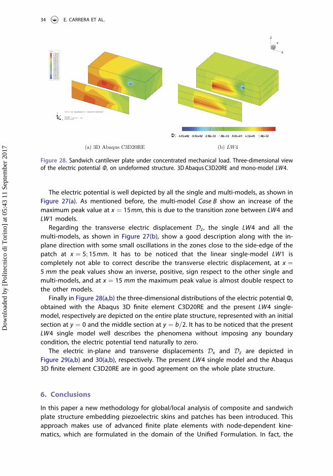
The electric potential is well depicted by all the single and multi-models, as shown inFigure 27(a). As mentioned before, the multi-model Case B show an increase of themaximum peak value at x ¼ 15mm, this is due to the transition zone between LW4 andLW1 models.
Regarding the transverse electric displacement Dz , the single LW4 and all themulti-models, as shown in Figure 27(b), show a good description along with the in-plane direction with some small oscillations in the zones close to the side-edge of thepatch at x ¼ 5; 15mm. It has to be noticed that the linear single-model LW1 iscompletely not able to correct describe the transverse electric displacement, at x ¼5 mm the peak values show an inverse, positive, sign respect to the other single andmulti-models, and at x ¼ 15 mm the maximum peak value is almost double respect tothe other models.
Finally in Figure 28(a,b) the three-dimensional distributions of the electric potential Φ,obtained with the Abaqus 3D finite element C3D20RE and the present LW4 single-model, respectively are depicted on the entire plate structure, represented with an initialsection at y ¼ 0 and the middle section at y ¼ b=2. It has to be noticed that the presentLW4 single model well describes the phenomena without imposing any boundarycondition, the electric potential tend naturally to zero.
The electric in-plane and transverse displacements Dx and Dz are depicted inFigure 29(a,b) and 30(a,b), respectively. The present LW4 single model and the Abaqus3D finite element C3D20RE are in good agreement on the whole plate structure.
6. Conclusions
In this paper a new methodology for global/local analysis of composite and sandwichplate structure embedding piezoelectric skins and patches has been introduced. Thisapproach makes use of advanced finite plate elements with node-dependent kine-matics, which are formulated in the domain of the Unified Formulation. In fact, the
EPOT
−5.325e+02−5.015e+02−4.706e+02−4.396e+02−4.086e+02−3.777e+02−3.467e+02−3.157e+02−2.848e+02−2.538e+02−2.228e+02−1.919e+02−1.609e+02−1.299e+02−9.897e+01−6.800e+01−3.703e+01−6.066e+00+2.490e+01+5.587e+01+8.684e+01+1.178e+02+1.488e+02+1.797e+02+2.107e+02
Step: Step−1Increment 1: Step Time = 1.000Primary Var: EPOT
ODB: Job−1.odb Abaqus/Standard 6.14−1 Sat May 06 15:14:26 CEST 2017
X
Y
Z
(a) 3D Abaqus C3D20RE (b) LW4
odb Abaqus/Standard 6.14−1 Sat May 06 15:14:26 CEST 2017
Figure 28. Sandwich cantilever plate under concentrated mechanical load. Three-dimensional viewof the electric potential Φ, on undeformed structure. 3D Abaqus C3D20RE and mono-model LW4.
34 E. CARRERA ET AL.
Dow
nloa
ded
by [
Polit
ecni
co d
i Tor
ino]
at 0
5:43
11
Sept
embe
r 20
17

finite element arrays of the generic plate element are formulated in terms of funda-mental nuclei, which are invariants of the theory approximation order and themodeling technique (ESL, LW). In this manner, the plate theory can vary within thesame finite elements with no difficulties. Thus, given a finite element model, thetheory approximation accuracy can be enriched locally in a very straightforwardmanner by enforcing the same kinematics at the interface nodes between kinemati-cally incompatible plate elements. The resulting global/local approach is very efficientbecause it does not employ any mathematical artifice to enforce the displacement/stress continuity, such as those methods based on Lagrange multipliers or overlap-ping regions.
(Avg: 75%)EFLX, EFLX3
−3.760e−03−3.277e−03−2.794e−03−2.311e−03−1.828e−03−1.345e−03−8.625e−04−3.796e−04+1.033e−04+5.862e−04+1.069e−03+1.552e−03+2.035e−03+2.518e−03+3.001e−03+3.484e−03+3.967e−03+4.450e−03+4.932e−03+5.415e−03+5.898e−03+6.381e−03+6.864e−03+7.347e−03+7.830e−03
Step: Step−1Increment 1: Step Time = 1.000Primary Var: EFLX, EFLX3
ODB: Job−1.odb Abaqus/Standard 6.14−1 Sat May 06 15:14:26 CEST 2017
X
Y
Z
(a) 3D Abaqus C3D20RE (b) LW4
Figure 30. Sandwich cantilever plate under concentrated mechanical load. Three-dimensional viewof the transverse electric displacement Dz , on undeformed structure. 3D Abaqus C3D20RE andmono-model LW4.
(Avg: 75%)EFLX, EFLX1
−4.981e−03−4.670e−03−4.360e−03−4.050e−03−3.740e−03−3.429e−03−3.119e−03−2.809e−03−2.498e−03−2.188e−03−1.878e−03−1.567e−03−1.257e−03−9.467e−04−6.364e−04−3.261e−04−1.574e−05+2.946e−04+6.049e−04+9.152e−04+1.226e−03+1.536e−03+1.846e−03+2.156e−03+2.467e−03
Step: Step−1Increment 1: Step Time = 1.000Primary Var: EFLX, EFLX1
ODB: Job−1.odb Abaqus/Standard 6.14−1 Sat May 06 15:14:26 CEST 2017
X
Y
Z
(a) 3D Abaqus C3D20RE (b) LW4
odb Abaqus/Standard 6.14−1 Sat May 06 15:14:26 CEST 2017
Figure 29. Sandwich cantilever plate under concentrated mechanical load. Three-dimensional viewof the in-plane electric displacement Dx , on undeformed structure. 3D Abaqus C3D20RE and mono-model LW4.
INTERNATIONAL JOURNAL OF SMART AND NANO MATERIALS 35
Dow
nloa
ded
by [
Polit
ecni
co d
i Tor
ino]
at 0
5:43
11
Sept
embe
r 20
17

The present node-dependent variable kinematic model allows to locally improve thesolution. Two main aspects can be highlighted: a reduction of computational costs withrespect to Layer-Wise single-model solutions, and a simultaneous multi-models global-local analysis can be performed in one-single analysis step. An accurate representationof secondary variables (mechanical stresses and electric displacements) in localizedzones is possible with DOFs reduction if an accurate distribution of the higher-orderkinematic capabilities is performed. On the contrary, the accuracy of the solution interms of primary variables (mechanical displacements and electric potential) valuesdepends on the global approximation over the whole structure. The efficacy of thenode-dependent variable kinematic and global/local models, thus, depends on thecharacteristics of the problem under consideration as well as on the required analysistype. The proposed methodology has been widely assessed in this paper by analyzingcomposite and sandwich plates embedding piezoelectric skins and patches, in sensorand actuator configurations, and shear actuated configuration, and by comparison withsolutions from the literature and those from finite element commercial tools. Futuredevelopments will deal with the extension of this global/local methodology to hier-archical shell theories and thermo-mechanical problems.
Acknowledgement
E. Carrera and G. M. Kulikov have been supported by the Russian Science Foundation (Grant No.15-19-30002) and the Russian Ministry of Education and Science (Grant No. 9.4914.2017).
Disclosure statement
No potential conflict of interest was reported by the authors.
Funding
This work was supported by the Russian Science Foundation [15-19-30002];
References
[1] R.D. Mindlin, Forced thickness-shear and flexural vibrations of piezoelectric crystal plates, J.Appl. Phys. 23 (1952), pp. 83–91. doi:10.1063/1.1701983
[2] E.P. EerNisse, Variational method for electroelastic vibration analysis, IEEE Transaction onSonics and Ultrasonics 14 (4) (1967), pp. 153–213. doi:10.1109/T-SU.1967.29431
[3] H.F. Tiersten and R.D. Mindlin, Forced vibrations of piezoelectric crystal plates, Q. Appl. Math. 20(2) (1962), pp. 107–126. doi:10.1090/qam/99964
[4] H.F. Tiersten, Linear piezoelectric plate vibrations, New York Plenum Press (1969).[5] D.A. Saravanos and P.R. Heyliger, Mechanics and computational models for laminated piezo-
electric beams, plates and shells, Appl. Mechanics Rev. 52 (10) (1999), pp. 305–324.doi:10.1115/1.3098918
[6] S. Kapuria, A coupled zig-zag third-order theory for piezoelectric hybrid cross-ply plates, J. Appl.Mechanics 71 (2004), pp. 604–618. doi:10.1115/1.1767170
[7] C. Ossadzow-David and M. Touratier, A multilayered piezoelectric shell theory, Compos. Sci.Technol. 64 (2004), pp. 2121–2158. doi:10.1016/j.compscitech.2004.03.005
36 E. CARRERA ET AL.
Dow
nloa
ded
by [
Polit
ecni
co d
i Tor
ino]
at 0
5:43
11
Sept
embe
r 20
17

[8] P. Heyliger and K.C. Pei, and D A Saravanos. Layerwise mechanics and finite element model forlaminated piezoelectric shells, Aiaa J. 34 (11) (1996), pp. 2353–2413. doi:10.2514/3.13401
[9] D. Ballhause, M. D’Ottavio, B. Kroplin, and E. Carrera, A unified formulation to assess multi-layered theories for piezoelectric plates, Comput. Struct. 83 (15–16) (2005), pp. 1217–1235.doi:10.1016/j.compstruc.2004.09.015
[10] M. D’Ottavio, D. Ballhause, B. Kroplin, and E. Carrera, Closed-form solutions for the free-vibration problem of multilayered piezoelectric shells, Comput. Struct. 84 (2006), pp. 1506–1524. doi:10.1016/j.compstruc.2006.01.030
[11] A. Benjeddou, J. Deu, and S. Letombe, Free vibrations of simply-supported piezoelectricadaptive plates: An exact sandwich formulation, Thin-Walled Structures 40 (2002), pp. 573–666. doi:10.1016/S0263-8231(02)00013-7
[12] R. Garcia Lage, C.M. Mota Soares, C.A. Mota Soares, and J.N. Reddy, Modelling of piezo-laminated plates using layerwise mixed finite elements, Comput. Struct. 82 (2004), pp. 1849–1863. doi:10.1016/j.compstruc.2004.03.068
[13] F. Moleiro, C.M. Mota Soares, C.A. Mota Soares, and J.N. Reddy, Assessment of a layerwisemixed least-squares model for analysis of multilayered piezoelectric composite plates, Comput.Struct. 108-109 (2012), pp. 14–30. doi:10.1016/j.compstruc.2012.04.002
[14] G.M. Kulikov and S.V. Plotnikova, Exact geometry piezoelectric solid-shell element based on the7-parameter model, Mech. Adva. Mat. Struct. 18 (2011), pp. 133–146. doi:10.1080/15376494.2010.496067
[15] G.M. Kulikov and S.V. Plotnikova, A new approach to three-dimensional exact solutions forfunctionally graded piezoelectric laminated plates, Compos. Struct. 106 (2013), pp. 33–46.doi:10.1016/j.compstruct.2013.05.037
[16] G. Rama, A 3-node piezoelectric shell element for linear and geometrically nonlinear dynamicanalysis of smart structures, Facta Univ. Ser. 15 (1) (2017), pp. 31–44. doi:10.22190/FUME170225002R
[17] T. Nestorovi, S. Shabadi, D. Marinkovi, and M. Trajkov, Modeling of piezoelectric smart struc-tures by implementation of a user defined shell finite element, Facta Univ. Ser. 11 (1) (2013), pp.1–12.
[18] Babushka, I., Chandra, J., & Flaherty, J. E. (Eds.). Adaptive Computational Methods for PartialDifferential Equations Vol. 16. Siam, Proceedings, College Park, PA, 1983.
[19] B.A. Szabo and I. Babuska, Finite element analysis, John Wiley & Sons (1991).[20] K.J. Bathe, Finite Element Procedure, Pearson Education, Inc., Prentice Hall, 1996.[21] D.M. Thompson and O.H. Jr Griffin, 2-D to 3-D Global/Local Finite Element Analysis of Cross-Ply
Composite Laminates, J. Reinf. Plast. Compos. 9 (1990), pp. 492–502. doi:10.1177/073168449000900506
[22] K.M. Mao and C.T. Sun, A refined global-local finite element analysis method, Int. J. Numer.Methods Eng. 32 (1991), pp. 29–43. doi:10.1002/(ISSN)1097-0207
[23] J.D. Whitcomb and K. Woo, Application of iterative global/local finite element analysis. part 1:linear analysis, Commun Numer Methods Eng 9 (9) (1993), pp. 745–756. doi:10.1002/cnm.1640090905
[24] J.D. Whitcomb and K. Woo, Application of iterative global/local finite element analysis. part 2:geometrically non-linear analysis, Commun Numer Methods Eng 9 (9) (1993), pp. 757–766.doi:10.1002/cnm.1640090906
[25] S. Valvano, and E. Carrera, Analysis of laminated composites and sandwich structures byvariable-kinematic mitc9 plate elements, j. Sandwich Structures Mater, (2016). doi: 10.1177/1099636216650988
[26] E. Carrera, A. Pagani, and S. Valvano, Shell elements with through-the-thickness variablekinematics for the analysis of laminated composite and sandwich structures, Composites Part.B 111 (2017), pp. 294–314. doi:10.1016/j.compositesb.2016.12.001
[27] Carrera and S. Valvano, A variable kinematic shell formulation applied to thermal stress oflaminated structures, J. Therm. Stresses 40 (7), 2017. doi: 10.1080/01495739.2016.1253439
INTERNATIONAL JOURNAL OF SMART AND NANO MATERIALS 37
Dow
nloa
ded
by [
Polit
ecni
co d
i Tor
ino]
at 0
5:43
11
Sept
embe
r 20
17

[28] Carrera and S. Valvano, Analysis of laminated composite structures with embedded piezo-electric sheets by variable kinematic shell elements, J. Intell. Mater Syst. Struct, 2017. doi:10.1177/1045389X17704913
[29] F. Brezzi and L.D. Marini, The three-field formulation for elasticity problems, GAMMMitteilungen 28 (2005), pp. 124–153. doi:10.1002/gamm.v28.2
[30] E. Carrera, A. Pagani, and M. Petrolo, Use of Lagrange multipliers to combine 1D variablekinematic finite elements, Comput. Struct. 129 (2013), pp. 194–206. doi:10.1016/j.compstruc.2013.07.005
[31] H. Ben Dhia, Multiscale mechanical problems: The arlequin method, C R Acad Sci IIb Mec 326(12) (1998), pp. 899–904.
[32] H. Ben Dhia, The arlequin method as a flexible engineering tool, Int. J. Numer. Methods Eng. 62(11) (2005), pp. 1442–1462. doi:10.1002/nme.1229
[33] H. Ben Dhia, Further insights by theoretical investigations of the multiscale arlequin method, Int. J.Multiscale Computational Eng. 6 (3) (2008), pp. 215–232. doi:10.1615/IntJMultCompEng.v6.i3
[34] H. Hu, S. Belouettar, M. Potier-Ferry, and E.M. Daya, Multi-scale modelling of sandwichstructures using the arlequin method. Part I: Linear modelling, Finite Elem. Anal. Des. 45 (1)(2008), pp. 37–51. doi:10.1016/j.finel.2008.07.003
[35] H. Hu, S. Belouettar, M. Potier-Ferry, E.M. Daya, and A. Makradi, Multi-scale nonlinear modellingof sandwich structures using the Arlequin method, Finite Elem. Anal. Des. 92 (2) (2010), pp.515–522.
[36] F. Biscani, G. Giunta, S. Belouettar, E. Carrera, and H. Hu, Variable kinematic beam elementscoupled via Arlequin method, Compos. Struct. 93 (2) (2011), pp. 697–708. doi:10.1016/j.compstruct.2010.08.009
[37] F. Biscani, G. Giunta, S. Belouettar, E. Carrera, and H. Hu, Variable kinematic plate elementscoupled via Arlequin method, Int. J. Numer. Methods Eng. 91 (2012), pp. 1264–1290.doi:10.1002/nme.v91.12
[38] F. Biscani, P. Nali, S. Belouettar, and E. Carrera, Coupling of hierarchical piezoelectric plate finiteelements via Arlequin method, J. Intell. Mater Syst. Struct. 23 (7) (2012), pp. 749–764.doi:10.1177/1045389X12437885
[39] E. Carrera, A. Pagani, and S. Valvano, Multilayered plate elements accounting for refined theoriesand node-dependent kinematics, Composites Part. B (2017). doi:10.1016/j.compositesb.2017.01.022
[40] S. Valvano and E. Carrera, Multilayered plate elements with node-dependent kinematics for theanalysis of composite and sandwich structures, Facta Univ. Ser. 15 (1) (2017), pp. 1–30.doi:10.22190/FUME170315001V
[41] K.J. Bathe and E. Dvorkin, A formulation of general shell elements - the use of mixed interpola-tion of tensorial components, Int. J. Numer. Methods Eng. 22 (1986), pp. 697–722. doi:10.1002/nme.1620220312
[42] K.J. Bathe and F. Brezzi. A simplified analysis of two plate bending elements-the MITC4 andMITC9 elements. Proceedings, Numerical Methods in Engineering: Theory and Applications,1987.
[43] K.J. Bathe and F. Brezzi, and S W Cho. The MICT7 and MITC9 plate bending elements, Comput.Struct. 32 (3–4) (1989), pp. 797–814. doi:10.1016/0045-7949(89)90365-9
[44] M.L. Bucalem and E. Dvorkin, Higher-order MITC general shell elements, Int. J. Numer. MethodsEng. 36 (1993), pp. 3729–3754. doi:10.1002/nme.1620362109
[45] J.N. Reddy, An evaluation of equivalent-single-layer and layerwise theories of composite lami-nates, Compos. Struct. 25 (1993), pp. 21–35. doi:10.1016/0263-8223(93)90147-I
[46] N.N. Rogacheva, The Theory of Piezoelectric Shells and Plates, CRC Press, Boca Raton, 1994.[47] M. Cinefra, S. Valvano, and E. Carrera, Thermal stress analysis of laminated structures by a
variable kinematic MITC9 shell element, J. Therm. Stresses 39 (2) (2016), pp. 121–141.doi:10.1080/01495739.2015.1123591
[48] M. Cinefra, S. Valvano, and E. Carrera, A layer-wise MITC9 finite element for the free-vibrationanalysis of plates with piezo-patches, Int. J. Smart Nano Mater. 6 (2) (2015), pp. 85–104.doi:10.1080/19475411.2015.1037377
38 E. CARRERA ET AL.
Dow
nloa
ded
by [
Polit
ecni
co d
i Tor
ino]
at 0
5:43
11
Sept
embe
r 20
17

[49] E. Carrera, Theories and finite elements for multilayered plates and shells: A unified compactformulation with numerical assessment and benchmarking, Arch Computational Methods Eng.10 (3) (2003), pp. 215–296. doi:10.1007/BF02736224
[50] E. Carrera, Multilayered shell theories accounting for layerwise mixed description, Part 1:Governing equations, Aiaa J. 37 (9) (1999), pp. 1107–1116. doi:10.2514/2.821
[51] E. Carrera, Multilayered shell theories accounting for layerwise mixed description, Part 2:Numerical evaluations, Aiaa J. 37 (9) (1999), pp. 1117–1124. doi:10.2514/2.822
[52] E. Carrera, M. Cinefra, and E.P.M. Abd Zappino, Finite Element Analysis of Structures throughUnified Formulation, John Wiley & Sons, 2014.
[53] P. Heyliger, Static behavior of laminated elastic/piezo-electric plates, Aiaa J. 32 (12) (1994), pp.2481–2484. doi:10.2514/3.12321
[54] C.T. Sun and X.D. Zhang, Use of thickness-shear mode in adaptive sandwich structures, SmartMater. Struct 4 (1995), pp. 202–206. doi:10.1088/0964-1726/4/3/007
[55] X.D. Zhang and C.T. Sun, Formulation of an adaptive sandwich beam, Smart Mater. Struct 5(1996), pp. 814–823. doi:10.1088/0964-1726/5/6/012
[56] A. Benjeddou, M. Trindade, and R. Ohayon, A unified beam finite element model for extensionand shear piezoelectric actuation mechanisms, J. Intell. Mater Syst. Struct. 8 (1997), pp. 1012–1025.
INTERNATIONAL JOURNAL OF SMART AND NANO MATERIALS 39
Dow
nloa
ded
by [
Polit
ecni
co d
i Tor
ino]
at 0
5:43
11
Sept
embe
r 20
17