Embed Size (px)
Citation preview
SICAMMultifunctional RecorderSICAM Q200 7KG97Communication
V02.10
Manual
E50417-C1040-C606-A4
Preface
Open Source Software
Table of Contents
User Information 1Communication Modbus 2Communication IEC 61850 3Communication DNP3 IP 4Glossary

iiNOTEFor your own safety, observe the warnings and safety instructions contained in this document, if available.
Disclaimer of LiabilityThis document has been subjected to rigorous technicalreview before being published. It is revised at regular inter-vals, and any modifications and amendments are includedin the subsequent issues. The content of this document hasbeen compiled for information purposes only. AlthoughSiemens AG has made best efforts to keep the document asprecise and up-to-date as possible, Siemens AG shall notassume any liability for defects and damage which resultthrough use of the information contained herein.This content does not form part of a contract or of businessrelations; nor does it change these. All obligations ofSiemens AG are stated in the relevant contractual agree-ments.Siemens AG reserves the right to revise this document fromtime to time.Document version: E50417-C1040-C606-A4.03Edition: 10.2017Version of the product described: V02.10
CopyrightCopyright © Siemens AG 2017. All rights reserved.The disclosure, duplication, distribution and editing of thisdocument, or utilization and communication of the contentare not permitted, unless authorized in writing. All rights,including rights created by patent grant or registration of autility model or a design, are reserved.
Registered Trademarks
SIPROTEC®, DIGSI®, SIGUARD®, SIMEAS®, and SICAM® areregistered trademarks of Siemens AG. Any unauthorizeduse is illegal. All other designations in this document canbe trademarks whose use by third parties for their ownpurposes can infringe the rights of the owner.
Preface
Purpose of the ManualThis manual describes the communication of the SICAM Q200 device.
Target AudienceThis manual is intended for project engineers, commissioning and operating personnel in electrical systemsand power plants.
ScopeThis manual is valid for SICAM Q200.
Indication of Conformity
This product complies with the directive of the Council of the European Communitieson harmonization of the laws of the Member States relating to electromagneticcompatibility (EMC Directive 2014/30/EU) and concerning electrical equipment for usewithin specified voltage limits (Low Voltage Directive 2014/35/EU).This conformity has been proved by tests performed according to the Council Directivein accordance with the generic standard EN 61000-6-5 (for EMC directive) and with theproduct standard EN 62586-1 (for Low Voltage Directive) by Siemens AGThe device is designed and manufactured for application in an industrial environment.The product conforms with the international standards of EN 62586 and the Germanstandard VDE 0415.
Other Standards
This product is UL-certified to Standard UL 61010-1, third edition, based on the Technical data.(UL File No.: E228586)
IND. CONT. EQ.69CA
Open-type Measuring Equipment2UD1
For further information see UL database on the internet: http://ul.com.Select Online Certifications Directory and insert E228586 under UL File Number.
Additional SupportFor questions about the system, please contact your Siemens sales partner.
SupportOur Customer Support Center provides a 24-hour service.Phone: +49 (180) 524-7000Fax: +49 (180) 524-2471
SICAM, Multifunctional Recorder, Manual 3E50417-C1040-C606-A4, Edition 10.2017

E-Mail: [email protected]
Training CoursesInquiries regarding individual training courses should be addressed to our Training Center:Siemens AGSiemens Power Academy TD Humboldtstraße 5990459 NürnbergGermany Phone: +49 (911) 433-7415Fax: +49 (911) 433-7929E-Mail: [email protected]: www.siemens.com/poweracademy
Notes on SafetyThis document is not a complete index of all safety measures required for operation of the equipment (moduleor device). However, it comprises important information that must be followed for personal safety, as well asto avoid material damage. Information is highlighted and illustrated as follows according to the degree ofdanger:
! DANGERDANGER means that death or severe injury will result if the measures specified are not taken.
² Comply with all instructions, in order to avoid death or severe injuries.
! WARNINGWARNING means that death or severe injury may result if the measures specified are not taken.
² Comply with all instructions, in order to avoid death or severe injuries.
! CAUTIONCAUTION means that medium-severe or slight injuries can occur if the specified measures are not taken.
² Comply with all instructions, in order to avoid moderate or minor injuries.
NOTICENOTICE means that property damage can result if the measures specified are not taken.
² Comply with all instructions, in order to avoid property damage.
Preface
4 SICAM, Multifunctional Recorder, ManualE50417-C1040-C606-A4, Edition 10.2017

iiNOTEImportant information about the product, product handling or a certain section of the documentationwhich must be given particular attention.
Qualified Electrical Engineering PersonnelOnly qualified electrical engineering personnel may commission and operate the equipment (module, device)described in this document. Qualified electrical engineering personnel in the sense of this manual are peoplewho can demonstrate technical qualifications as electrical technicians. These persons may commission,isolate, ground and label devices, systems and circuits according to the standards of safety engineering.
Proper UseThe equipment (device, module) may be used only for such applications as set out in the catalogs and thetechnical description, and only in combination with third-party equipment recommended and approved bySiemens.Problem-free and safe operation of the product depends on the following:• Proper transport
• Proper storage, setup and installation
• Proper operation and maintenanceWhen electrical equipment is operated, hazardous voltages are inevitably present in certain parts. If properaction is not taken, death, severe injury or property damage can result:• The equipment must be grounded at the grounding terminal before any connections are made.
• All circuit components connected to the power supply may be subject to dangerous voltage.
• Hazardous voltages may be present in equipment even after the supply voltage has been disconnected(capacitors can still be charged).
• Operation of equipment with exposed current-transformer circuits is prohibited. Before disconnecting theequipment, ensure that the current-transformer circuits are short-circuited.
• The limiting values stated in the document must not be exceeded. This must also be considered duringtesting and commissioning.
Used Symbols
No. Symbol Description1 Direct current
IEC 60417-50312 Alternating current
IEC 60417-5032
3 Direct and alternating currentIEC 60417-5033
4 3-phase alternating current
5 Earth (ground) terminalIEC 60417-5017
6 Protective conductor terminalIEC 60417-5019
Preface
SICAM, Multifunctional Recorder, Manual 5E50417-C1040-C606-A4, Edition 10.2017

6 SICAM, Multifunctional Recorder, ManualE50417-C1040-C606-A4, Edition 10.2017

Open Source Software
The product contains, among other things, Open Source Software developed by third parties. The OpenSource Software used in the product and the license agreements concerning this software can be found in theReadme_OSS. These Open Source Software files are protected by copyright. Your compliance with thoselicense conditions will entitle you to use the Open Source Software as foreseen in the relevant license. In theevent of conflicts between Siemens license conditions and the Open Source Software license conditions, theOpen Source Software conditions shall prevail with respect to the Open Source Software portions of the soft-ware. The Open Source Software is licensed royalty-free. Insofar as the applicable Open Source SoftwareLicense Conditions provide for it you can order the source code of the Open Source Software from yourSiemens sales contact - against payment of the shipping and handling charges - for a period of at least 3 yearssince purchase of the Product. We are liable for the Product including the Open Source Software contained init pursuant to the license conditions applicable to the Product. Any liability for the Open Source Softwarebeyond the program flow intended for the Product is explicitly excluded. Furthermore any liability for defectsresulting from modifications to the Open Source Software by you or third parties is excluded. We do notprovide any technical support for the Product if it has been modified.
SICAM, Multifunctional Recorder, Manual 7E50417-C1040-C606-A4, Edition 10.2017

8 SICAM, Multifunctional Recorder, ManualE50417-C1040-C606-A4, Edition 10.2017

Table of Contents
Preface..........................................................................................................................................................3
Open Source Software..................................................................................................................................7
1 User Information........................................................................................................................................ 111.1 General User Information.................................................................................................. 12
2 Communication Modbus............................................................................................................................ 132.1 Functions, Properties and Exception Responses for Modbus TCP Server and Modbus
RTU (Slave)....................................................................................................................... 142.2 Functions and Properties for Modbus RTU Master.............................................................. 162.3 Exception Responses from the Modbus Gateway............................................................... 182.4 Modbus Registers..............................................................................................................192.4.1 Modbus Specifications................................................................................................. 192.4.2 Mapping Documentation of the SICAM Devices............................................................ 192.5 Modbus Data Format.........................................................................................................212.5.1 Data Types - General....................................................................................................212.5.2 Data Type - Measured Value (Read)..............................................................................212.5.3 Data Type - Date/Time (Read and Write)....................................................................... 232.5.4 Data Type - Indications (Read)......................................................................................242.5.5 Data Type - Controllable Indications (Read and Write)...................................................242.5.6 Data Type - Counter (Read).......................................................................................... 25
3 Communication IEC 61850......................................................................................................................... 273.1 General.............................................................................................................................28
4 Communication DNP3 IP.............................................................................................................................294.1 General.............................................................................................................................30
Glossary...................................................................................................................................................... 31
SICAM, Multifunctional Recorder, Manual 9E50417-C1040-C606-A4, Edition 10.2017

10 SICAM, Multifunctional Recorder, ManualE50417-C1040-C606-A4, Edition 10.2017

User Information
1.1 General User Information 12
1
SICAM, Multifunctional Recorder, Manual 11E50417-C1040-C606-A4, Edition 10.2017

General User InformationThis manual describes how SICAM Q200 communicates with peripheral devices/systems. For detailed deviceinformation, see the device manual.
CommunicationThe communication interfaces of SICAM Q200 make 4 communication types possible using the correspondingcommunication protocols:• Modbus TCP Server via Ethernet interface
• Modbus RTU (master and slave) via RS485 interface
• Modbus TCP to Modbus RTU Gateway
• IEC 61850 via Ethernet interfaceTo communicate with control systems and other process automation equipment and to transmit, for example,operational measured values, metered values, indications, and load profiles, the device provides 2 switchableEthernet interfaces and an RS485 interface with 2 connectors for serial communication.If parameterized accordingly, the device can communicate over the Ethernet interface and simultaneouslyover the serial interface. It is possible, for example, to parameterize and retrieve data over the Ethernet inter-face, while the serial interface handles the protocol traffic with a Modbus slave device.
Communication via Ethernet InterfaceThe device has 2 Ethernet ports which can be used seperately, or be combined to form a "Daisy-chain".Via the Ethernet interface the following functions are supported:• Parameterization, analysis and diagnosis with HTML pages
• DHCP (Dynamic Host Configuration Protocol)1 to assign the network configuration (IP address etc.) toclients in an Ethernet network with DHCP server
• Time synchronization via NTP
• Data transfer (measured data, metered values, load profiles and indications/events) to connected devicesvia Modbus TCP or IEC 61850-Server
• Data transfer to SICAM PAS/PQS for waveform record (COMTRADE IEEE...) and power quality and histor-ical data (PQDIF IEEE...)
SICAM Q200 supports the following TCP/IP services (TCP/IP protocol stack):• TCP/IP IPv4
• DHCP client (Dynamic Host Configuration Protocol)
• NTP (Network Time Protocol)
• HTTPS
• SNMPv3 (Simple Network Management Protocol)
Communication via RS485 InterfaceSICAM Q200 includes a serial interface, which communicates via two parallel switched RJ45 plug connectors.The RS485 interface allows for Modbus RTU Master and Modbus RTU Slave functionality. This interfacesupports the transmission of the measured data, metered values, load profiles, indications, and time synchro-nization.
1.1
1 DHCP cannot be used with IEC 61850 enabled.
User Information1.1 General User Information
12 SICAM, Multifunctional Recorder, ManualE50417-C1040-C606-A4, Edition 10.2017

Communication Modbus
2.1 Functions, Properties and Exception Responses for Modbus TCP Server and Modbus RTU(Slave)
14
2.2 Functions and Properties for Modbus RTU Master 162.3 Exception Responses from the Modbus Gateway 182.4 Modbus Registers 192.5 Modbus Data Format 21
2
SICAM, Multifunctional Recorder, Manual 13E50417-C1040-C606-A4, Edition 10.2017

Functions, Properties and Exception Responses for Modbus TCPServer and Modbus RTU (Slave)
Modbus Functions for Modbus TCP Server and Modbus RTU (Slave)The Modbus TCP server and Modbus RTU (slave) of SICAM Q200 supports the following Modbus functions:
Table 2-1 Supported Modbus TCP Server and Modbus RTU (slave) Functions
FunctionNumber
Function Name Description
03(03H)
Read Holding Regis-ters
Reading one or more holding registers from the Modbus serverUp to 125 registers can be read with one message.
06(06H)
Write Single Register Writing a holding registerFunction 16 is used for writing multiple holding register using oneModbus message.
16(10H)
Write Multiple Regis-ters
Writing one or more holding registersUp to 123 registers can be written with one message.
Properties for Modbus TCP Server
• Connection-oriented Ethernet protocol based on TCP/IP
• Use of IP addresses for addressing individual components connected to the bus (bus nodes)
• The Modbus TCP protocol has the TCP port number 502 reserved on the server side. It is possible to use aparameterized port number.
• All data types in the Modbus TCP messages which are larger than 1 byte are stored in the big-endianformat, that is the most significant byte (MSB) is stored at the lowest register address and is transmittedfirst.
• Communication sequence:– The client sends a request to the server to start a data transmission from the server to the client.– If the requested data are not available, the server sends an error feedback to the client.
• The Modbus TCP data packet has a maximum size of 260 bytes:– 253 bytes max. for data and– 7 bytes for the Modbus TCP header
Properties for Modbus RTU (Slave)
• Client-server protocol
• All clients have a unique address in the range from 1 to 247.
• Packets with the address = 0 are forwarded to all clients (broadcast).
• The individual data bytes in the messages are transmitted asynchronously with 11 bits:– 1 start bit,– 8 data bits,– 1 parity bit and 1 stop bit or– No parity bit and 2 stop bits
• Single messages are separated by bus silent intervals of at least 3.5 character times and end with a CRCcode for error detection.
• RS485 is used as interface.
2.1
Communication Modbus2.1 Functions, Properties and Exception Responses for Modbus TCP Server and Modbus RTU (Slave)
14 SICAM, Multifunctional Recorder, ManualE50417-C1040-C606-A4, Edition 10.2017

• The Modbus RTU message has a maximum size of 256 bytes:– 1 byte server address– 253 bytes for data– 2 bytes for CRC
Exception Responses for Modbus TCP Server and Modbus RTU (slave)The Modbus server performs a series of consistency checks of the Modbus client requests, and if errors (forexample request to read a nonexistent register) are detected, it generates Modbus exception codes which aresignaled to the Modbus client in exception responses messages.The messages contain the following codes:
Exception Code 01 - ILLEGAL_FUNCTION
• The Modbus client uses a function that is not supported by the Modbus server of the SICAM Q200. Thesupported Modbus functions are listed in the next chapter.
Exception Code 02 - ILLEGAL_DATA_ADDRESS
• An attempt is made to read out or write to a nonexistent Modbus register.
• An attempt is made to read out or write to too many registers. A Modbus message enables reading out125 holding registers and writing to 123 holding registers maximum.
• The Modbus client tries to write to a register in the Modbus server for which only read access is allowedaccording to the Modbus mapping.
Exception Code 03 - ILLEGAL_DATA_VALUE
• The redundancy client addresses a register that does not allow access to partial data. The register has acomplex data structure and is distributed across several registers. The register can be read or written onlyas a whole.
• The Modbus client tries to write to the Modbus server for which the access rights are set to "read only".
Exception Code 04 - SERVER_FAILURE
• Error during the time format conversion in the Modbus server because a faulty date/time format wasreceived via Modbus, for example month format > 12.
iiNOTEThe parameterization of the Ethernet communication via the Ethernet interface are described in detail inthe SICAM Q200 device manual.
Communication Modbus2.1 Functions, Properties and Exception Responses for Modbus TCP Server and Modbus RTU (Slave)
SICAM, Multifunctional Recorder, Manual 15E50417-C1040-C606-A4, Edition 10.2017

Functions and Properties for Modbus RTU MasterSupported Modbus Register Sets
• Coil status registers (0x references, read only)
• Input status registers (1x references, read only)
• Input registers (3x references, read only)
• Holding registers (4x references, read only)
Supported Modbus FunctionsThe Modbus RTU Master of SICAM Q200 supports the following Modbus functions:
Table 2-2 Supported Modbus RTU Master Functions
FunctionNumber
Function Name Description
01 (0x01H) Read Coil Status Reading one or several coil status registers of aModbus slave
02 (0x02H) Read Discrete Inputs (Read InputStatus)
Reading one or several input status registers of aModbus slave
03 (0x03H) Read Holding Registers Reading one or several holding registers of a Modbusslave
04 (0x04H) Read Input Registers Reading one or several input registers of a Modbusslave
Support of Modbus Slave DevicesThe Modbus RTU master supports 16 Modbus slave devices each with:• 15 readable measured values per Modbus slave device
• 6 readable indications from each Modbus slave device
iiNOTEIf more than the specified number of measured values and/or indications have to be read by a Modbusslave device, it is possible to assign the same address to multiple devices when configuring the devicesconnected to the Modbus master in SICAM Q200. The data of all devices with the same address are thenqueried by a Modbus slave device.
Properties of the Modbus RTU Master
• Master-Slave protocol
• The individual data bytes in the messages are transmitted asynchronously with 11 bits:1 start bit,8 data bits,1 parity bit and 1 stop bit orNo parity bit and 2 stop bits
• Single messages are separated by bus silent intervals of at least 3.5 character times and end with a CRCcode for error detection.
• RS485 is used as interface.
2.2
Communication Modbus2.2 Functions and Properties for Modbus RTU Master
16 SICAM, Multifunctional Recorder, ManualE50417-C1040-C606-A4, Edition 10.2017

• The Modbus RTU message has a maximum size of 256 bytes:1 byte server address253 bytes for data2 bytes for CRC
iiNOTEThe parameterization of the serial communication via the RS485 interface, the Modbus slave devices, andthe associated mapping are described in detail in the SICAM Q200 device manual.
Communication Modbus2.2 Functions and Properties for Modbus RTU Master
SICAM, Multifunctional Recorder, Manual 17E50417-C1040-C606-A4, Edition 10.2017

Exception Responses from the Modbus GatewayIf a request from the Modbus gateway cannot be forwarded to the associated Modbus slave device or theModbus slave device does not respond, the Modbus gateway sends Modbus exception codes in exceptionresponses messages to the Modbus TCP client.The messages contain the following codes:• Exception code 10 GATEWAY_PATH_UNAVAILABLE
The gateway function was activated in the SICAM Q200 at the Ethernet interface settings, but ModbusRTU master was not selected as serial protocol.
• Exception code 11 GATEWAY_TARGET_DEVICE_FAILED_TO_RESPONDNo response from the Modbus slave device to which the request message was sent according to the unitID (observing the parameterized response time-out and message repetitions).
iiNOTEThe Modbus RTU master and the Modbus gateway function can be operated in parallel.
2.3
Communication Modbus2.3 Exception Responses from the Modbus Gateway
18 SICAM, Multifunctional Recorder, ManualE50417-C1040-C606-A4, Edition 10.2017

Modbus Registers
Modbus Specifications
iiNOTEThe Modbus specification with a detailed explanation of the Modbus protocol is provided in:• Modbus over Serial Line
Specification & Implementation Guidehttp://www.modbus.org
• Modbus Application Protocol Specificationhttp://www.modbus.org
• Modbus Messaging on TCP/IP Implementation Guidehttp://www.modbus.org
Generally, we have to differentiate between the following elements in Modbus:• The register number
• The register address in Modbus messages
Register NumberThe register number characterizes a Modbus register using a 5-digit or 6-digit decimal number where the digitwith the highest value defines the register type:• 0 – coil status register
• 1 – input status register
• 3 – input register
• 4 – holding registerCounting of the register number starts at 1 for each register type, for example, for the 5-digit display:• 00127 = coil status register 127 (alternatively: coil 127)
• 400108 = holding register 108
Register AddressAll address data in Modbus messages refer to the value 0. Therefore, register number and register address arerelated as follows:• register address = register number - 1The following applies to the above examples:• Coil 127 is addressed as 126 (007Ehex) in a Modbus message to query or describe the coil status register.
• 400108 is addressed as 107 (006Bhex) in a Modbus message to query or describe the holding register.
Mapping Documentation of the SICAM Devices
The Modbus bus mapping documents for the individual SICAM devices use the register number to reference apiece of information in the Modbus register set.
iiNOTEYou find the Modbus bus mapping document (Excel table) for the SICAM Q200 devices under: https://www.siemens.com/sicam-q200
2.4
2.4.1
2.4.2
Communication Modbus2.4 Modbus Registers
SICAM, Multifunctional Recorder, Manual 19E50417-C1040-C606-A4, Edition 10.2017

Only holding registers are used for SICAM Q200. All measured values, indications, metered values etc. arestored in these holding registers.Characterization of the register type (holding register) in the highest digit of the register number is not used inthe Modbus documentation of SICAM Q200.
iiNOTEFor the access to measured values, the measured values read with a telegram must be exclusively in thisrange. The addressed address range in a requesting telegram must not exceed the register range or fallbelow this range.
Example:If the average values of the harmonics of the voltage at the phases a, b, and c must be read, 3 requestingtelegrams must be sent. Each of these telegrams contains the register range entered for these values (or a partof it) for phases a, b, and c.In SICAM PQS, the user must define different corresponding requesting groups for this, for example:
[sc_PQS figure, 1, en_US]
Figure 2-1 Settings in SICAM PQS
Communication Modbus2.4 Modbus Registers
20 SICAM, Multifunctional Recorder, ManualE50417-C1040-C606-A4, Edition 10.2017

Modbus Data Format
Data Types - General
The following data types are used for storing variables in the Modbus registers.• Measured value
• Date/time
• Indication
• Controllable indication
• Counter
• String
iiNOTEThe following convention applies when storing variables consisting of more complex data types to theModbus holding register (that is variables which are larger than a holding register, for example 32-bitmeasured values):The register with the lowest address contains the most significant byte (MSB), the register with the highestaddress contains the least significant byte (LSB).
Data Type - Measured Value (Read)
The Measured Value data type is transferred into 2 holding registers in 32-bit floating-point format (singleprecision) according to IEEE standard 754.
Structure of the FormatThe 32-bit floating-point format consists of a sign bit (S), exponent and mantissa:
[dw_MeasuredValue, 1, en_US]
Figure 2-2 Data Type - Measured Value
Value Range
The 32-bit floating-point format has the value range: ±(10-38 to 10+38).
Value of the Measured ValuesThe value of a measured value is obtained as follows:Exponent = 0: Resulting value = 0Exponent = 255, mantissa = 0: Resulting value = (-1)<sign> * +InfExponent = 255, mantissa not equal to 0: Resulting value = NaN0 < Exponent < 255: Resulting value = (-1)<sign> * 2 (<exponent> - 127) * 1, <mantissa>
2.5
2.5.1
2.5.2
Communication Modbus2.5 Modbus Data Format
SICAM, Multifunctional Recorder, Manual 21E50417-C1040-C606-A4, Edition 10.2017

Status and Quality InformationSICAM Q200 uses floating-point numbers with the exponent 255 (Inf, NaN) to display status information ofthe measured values:
Table 2-3 Floating-point Numbers
Floating-point Number(Hexadecimal)
State Remark
7F800000H +Inf Overflow Measured value overflow7F800001H NaN Invalid For example, frequency not measured because mains voltage
too small(< 15 % Vrated)
7F800002H NaN Not calculated Measured value is not calculated, for instance because it doesnot exist in the selected network type.
Accuracy of the Floating-point NumbersThe 32-bit floating-point numbers have a 23-bit mantissa. Integer numbers can be represented in thefollowing ranges without loss of accuracy:• Binary: ±(1)111 1111 1111 1111 1111 1111
• Hexadecimal: ±FF FF FF
• Decimal: ±1677721632-bit floating-point numbers are accurate to about 7 decimal digits. An accuracy of 4 decimal digits (0.2measuring error) is required for measuring alternating current quantities.
Communication Modbus2.5 Modbus Data Format
22 SICAM, Multifunctional Recorder, ManualE50417-C1040-C606-A4, Edition 10.2017

Data Type - Date/Time (Read and Write)
The Date/Time data type is used to transmit the local time. The following format is used:
[dw_DataTime, 2, en_US]
Figure 2-3 Data Type - Date/Time
Data/Time Status10H set: Daylight saving time active20H set: Date/time error: equivalent to FAIL bit, see Device Manual SICAM Q200, chapter Time Synchroniza-tion.
iiNOTEFor the time synchronization via Ethernet, Siemens recommends the use of NTP.
The date and time can be transmitted in 64-bit format or in 32-bit format.• 64-bit format:
The 4 registers 0065 to 0068 (time and date) are transmitted in one message.
• 32-bit format:The registers are transmitted in 2 messages. The 1st message contains the registers 0067 and 0068(date), the 2nd message contains the registers 0065 and 0066 (time). The time synchronization onlytakes effect when the time has been completely transmitted.
2.5.3
Communication Modbus2.5 Modbus Data Format
SICAM, Multifunctional Recorder, Manual 23E50417-C1040-C606-A4, Edition 10.2017

Data Type - Indications (Read)
The Indications data type is represented by two bits in holding registers:
[dw_Indications, 1, en_US]
Figure 2-4 Data Type - Indications
Where:• Q: status/quality bit: 0 = OK, 1 = invalid
• V: Value bit: 0 = OFF, 1 = ON
Status or Quality Bit QIf the indication is invalid, the quality bit is set to 1. The value bit can be ignored in this case.Example: The power frequency is invalid if the voltage is smaller than 15 % of the rated voltage when meas-uring the frequency. Any limit violation indication based on this value is also invalid.
Value Bit VThe value bit indicates whether an indication is ON (=1) or OFF (=0).
Data Type - Controllable Indications (Read and Write)
The Controllable Indications data type is needed for:• The binary outputs of the SICAM Q200
• Processing internal device commands (for example resetting the energy counters).The holding register is used for read and write access in this context.
Use as Read Register
[dw_ControllableIndications_Read, 1, en_US]
Figure 2-5 Data Type - Controllable Indications - Read Register
Where:• Q: status/quality bit: 0 = OK, 1 = invalid
• V: Value bit: 0 = OFF, 1 = ON
2.5.4
2.5.5
Communication Modbus2.5 Modbus Data Format
24 SICAM, Multifunctional Recorder, ManualE50417-C1040-C606-A4, Edition 10.2017

Use as Write Register
[dw_ControllableIndications_Write, 1, en_US]
Figure 2-6 Data Type - Controllable Indications - Write Register
This data format enables up to 8 commands to be transmitted via the holding register for which the ON/OFFbits are set to either 0/1 or to 1/0. If these bits are set to 0/0 or 1/1, no evaluation will be performed.
Data Type - Counter (Read)
GeneralWith the Counter data type, units of energy are transmitted as counter pulses.To calculate the primary value, the conversion factor 'Energy per counter pulse' is output as the MeasuredValue data type in addition to the counter pulses. The primary value is calculated as follows:
Primary value = number of counter pulses * energy per counter pulse
The following information is sent to each counter using the Modbus protocol:• Counter pulses as 32-bit values (with sign)
• Separate status indications for invalid and overflow for each counter
• Energy per counter pulse in floating-point format for measured values
Counter Pulses32-bit integers with sign allow a maximum of ±2 147 483 647 counter pulses before the counter overflows.The Counter data type is structured as follows:
[dw_CounterPulses, 1, en_US]
Figure 2-7 Data Type - Counter - Counter Pulses - Read Register
Bit S (Sign)Reserved for negative metered values.
Quality InformationThe two following quality bits are stored for each counter in separate holding registers:• Overflow OV: The internal counter pulse exceeds 31 bits. The Overflow bit is reset once the counter has
been reset.
• Invalid IV: The counter value is invalid due to a reset/device start. The bit is deleted 1 min after the devicestart.
2.5.6
Communication Modbus2.5 Modbus Data Format
SICAM, Multifunctional Recorder, Manual 25E50417-C1040-C606-A4, Edition 10.2017
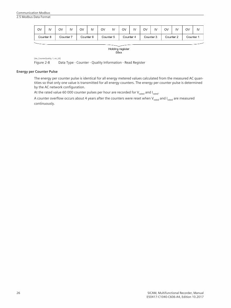
[dw_CounterQuality, 1, en_US]
Figure 2-8 Data Type - Counter - Quality Information - Read Register
Energy per Counter PulseThe energy per counter pulse is identical for all energy metered values calculated from the measured AC quan-tities so that only one value is transmitted for all energy counters. The energy per counter pulse is determinedby the AC network configuration.At the rated value 60 000 counter pulses per hour are recorded for Vrated and Irated.A counter overflow occurs about 4 years after the counters were reset when Vrated and Irated are measuredcontinuously.
Communication Modbus2.5 Modbus Data Format
26 SICAM, Multifunctional Recorder, ManualE50417-C1040-C606-A4, Edition 10.2017

Communication IEC 61850
3.1 General 28
3
SICAM, Multifunctional Recorder, Manual 27E50417-C1040-C606-A4, Edition 10.2017
GeneralThe IEC 61850 protocol is also used for communication via the Ethernet interface. The IEC 61850 specificationwith a detailed explanation of the protocol is given in “International Standard IEC 61850”. The device supportsIEC 61850, Edition 2.You can find the following information about the communication protocol IEC 61850 server of the SICAMQ200 in separate documents under https://www.siemens.com/sicam-q200:• Logical nodes (Reporting of operational values)
• PIXIT (with PICS and TICS)
• File transfer:– Power-Quality data in PQDIF format– Fault records in COMTRADE format
3.1
Communication IEC 618503.1 General
28 SICAM, Multifunctional Recorder, ManualE50417-C1040-C606-A4, Edition 10.2017

Communication DNP3 IP
4.1 General 30
4
SICAM, Multifunctional Recorder, Manual 29E50417-C1040-C606-A4, Edition 10.2017

GeneralThe DNP3 IP protocol is also used for communication via the Ethernet interface TCP/IP. The DNP3 IP specifica-tion with a detailed explanation of the protocol is given in the IEEE Standard for Electric Power SystemsCommunications - Distributed Network Protocol (DNP3) IEEE Std 1815-2012.For details of the DNP3 IP protocol implemented in SICAM Q200, see the DNP3 Device Profile.For information on the configuration of DNP3 IP, see chapter 2.7.4.2 in the Q200 device manual. You can findthe device manual under https://www.siemens.com/sicam-q200.
4.1
Communication DNP3 IP4.1 General
30 SICAM, Multifunctional Recorder, ManualE50417-C1040-C606-A4, Edition 10.2017

Glossary
+InfStands for Infinity and denotes a measured-value overflow. Extremely large number or infinitely positivenumber
ACAlternating Current
Big-Endian formatThe most significant byte is stored first, that is at the memory location with the lowest address.
ClientDevice in the communication network that sends data requests or commands to the server devices andreceives responses from them
CRC errorCyclic Redundancy Check: The cyclic redundancy check is a method of determining a test value for data (e.g.for data transmission in computer networks) with the purpose to detect errors during the transmission orduplication of data.
DHCPDynamic Host Configuration Protocol enables the network configuration to be assigned to the devices by aDHCP server
DNPDistributed Network Protocol
EthernetA family of computer networking technologies commonly used in local area networks (LANs) and metropol-itan area networks (MANs)
GatewayEnables networks based on different protocols to communicate with each other
Holding registerArea for representing data in Modbus communication
IECInternational Electrotechnical Commission, standards organization
IPInternet Protocol
SICAM, Multifunctional Recorder, Manual 31E50417-C1040-C606-A4, Edition 10.2017

IP addressAddresses in computer networks based on the Internet protocol
Limit violationA value exceeding or falling under a parameterized limiting value.
LSBLeast Significant Bit
ModbusThe Modbus protocol is a communication protocol based on a client-server architecture.
Modbus RTUModbus Remote Terminal Unit: Modbus protocol type for transmitting data over serial networks (e.g. RS485)
Modbus TCPModbus Transmission Control Protocol: Modbus protocol type for transmitting data as TCP/IP packets; TCP port502 is reserved for Modbus TCP.
MSBMost Significant Bit
NaNNot a Number means "invalid": Result of an invalid computing operation or used to indicate a special meas-ured-values status or quality information
NTPNetwork Time Protocol: Standard for synchronizing clocks in computer systems using packet-based communi-cation networks
Response timeoutTime within which the Modbus slave has to respond to a request from Modbus Master
RS485Interface standard for digital, wire-based, differential, serial data transmission
RTUSee Modbus Remote Terminal Unit
ServerSends data upon request by the client
SNMPSimple Network Management Protocol: Serves for monitoring and controlling network elements of a centralstation
TCP/IPTransmission Control Protocol/Internet Protocol: Family of network protocols
Glossary
32 SICAM, Multifunctional Recorder, ManualE50417-C1040-C606-A4, Edition 10.2017