Embed Size (px)
Citation preview

1
Multifunction Timer H3DE
Analog Set Multifunction TimersIn Slim 22.5 mm DesignFor Track Mounting
H Wide AC/DC power supply range(24 to 230 VAC/DC) minimizes inventory
H 12 VDC available in H3DE-M model
H Programmable contacts (available in-M2 and -S2 models) can enable anddisable a self-holding relay circuit
H Eight operating modes in the H3DE-M(four in the H3DE-S) offer wideapplication flexibility
H Time setting range 0.10 sec to 120 hrs
H Finger protection terminal block
Ordering InformationJ TIMER
Description Part number
Contact output Supply voltage Multifunctional Standard
DPDT (time-limit output SPDT);and switchable SPDT(time-limit←→ instantaneous)
12 VDC H3DE-M2 DC12 —
(time-limit←→ instantaneous)24 to 230VAC/DC
H3DE-M2 AC/DC24-230 H3DE-S2 AC/DC24-230
SPDT (time-limit output SPDT) H3DE-M1 AC/DC24-230 H3DE-S1 AC/DC24-230
J MODEL NUMBER LEGEND
H3DE-j-j-j
1 2 3
1. M: Multifunction typeS: Standard type
2. 1: SPDT2: DPDT
3. Supply voltage
J ACCESSORIES (ORDER SEPARATELY)
Item Description Part number
Mounting track 50 cm (l) x 7.3 mm (t) PFP-50N
1 m (l) x 7.3 mm (t) PFP-100N
1 m (l) x 16 mm (t) PFP-100N2
End plate PFP-M
Spacer PFP-S

H3DEH3DE
2
SpecificationsJ GENERAL
Item H3DE-M2 H3DE-M1 H3DE-S2 H3DE-S1
Operating mode A: ON-delay (Signal or Power)B: Repeat-cycle OFF start (Signal or Power)B2: Repeat-cycle ON start (Signal or Power)C: Signal ON-/OFF-delayD: Signal OFF-delayE: Interval (Signal or Power)G: Signal ON-/OFF-delayJ: One-shot (Signal or Power)
A: ON-delayB2: Repeat-cycle ON startE: IntervalJ: One-shot
Terminal block Clamps two 2.5 mm2 max. bar terminals without sleeves.
Terminal screw tighteningtorque
0.98 N S m max. approx. 10 kgf S cm max.
Input type Voltage input ---
Output type Relay: DPDT Relay: SPDT Relay: DPDT Relay: SPDT
Mounting method DIN track mounting (See Note.)
Attachment Nameplate
Approved standards UL508, CSA 22.2 No.14Conforms to EN61812-1, IEC60664-1 (VDE0110) 4 kV/2, VDE0106/P100Output category according to IEC60947-5-1 (AC-13; 250 V 5A/AC-15; 250 V 3 A/DC-13; 30 V 0.1 A)
Note: Can be mounted to 35-mm DIN track with a plate thickness of 1 to 2.5 mm.
J TIME RANGES
Time scale display Time unit display
seconds min hrs 10 h
x 0.1 0.1 to 1.2 s 0.1 to 1.2 min 0.1 to 1.2 h 1 to 12 h
x 1 1 to 12 s 1 to 12 min 1 to 12 h 10 to 120 h
Note: When the main dial is set to “0” for all settings, the output will operate instantaneously.
J RATINGS
Rated supply voltage(See Notes 1 and 2.)
24 to 230 VAC/DC (50/60 Hz)12 VDC (H3DE-M2 model only)
Operating voltage range 85% to 110% of rated supply voltage
Power reset Minimum power-off time: 0.1 s
Reset voltage 2.4 VAC/DC max.
Powerconsumption(S N t 3 )
H3DE-M1 AC: approx. 4.3 VA (2.2 W) at 230 VACDC: approx. 0.7 W at 24 VDCp
(See Note 3.) H3DE-M2 AC: approx. 4.8 VA (2.4 W) at 230 VACDC: approx. 1.0 W at 24 VDC
H3DE-S1 AC: approx. 2.7 VA (1.6 W) at 230 VACDC: approx. 0.7 W at 24 VDC
H3DE-S2 AC: approx. 3.2 VA (1.9 W) at 230 VACDC: approx. 1.0 W at 24 VDC
Voltage input Max. permissible capacitance between input lines (terminals B1 and A2) : 2000 pFLoad connectable in parallel with inputs (terminals B1 and A2)H-level: 20.4 to 253 VAC/DCL-level: 0 to 2.4 VAC/DC
Control output Contact output: 5 A at 250 VAC with resistive load (cosφ = 1); 5 A at 30 VDC with resistiveload (cosφ = 1)
Ambient temperature Operating: --10°C to 55°C (14 to 131°F) with no icingStorage: --25°C to 65°C (--13°F to 149°F) with no icing
Ambient humidity Operating: 35% to 85%
Note: 1. DC ripple rate: 20% max.2. Since an inrush current of 0.25 A will occur when using the power supply voltage at 24 VDC, pay careful attention when turning
on or off the power supply to the Timer with a solid-state output such as a sensor.3. The power consumption is for mode A (ON-delay) after the Timer counts the time-up time and for the AC input at 50 Hz. The
power consumption of the H3DE-Mj includes the input circuit with the B1 and A1 terminals short-circuited.

H3DEH3DE
3
J CHARACTERISTICS
Accuracy of operating time ±1% max. of FS (±1% ±10 ms max. at 1.2-s range) (See Note 1.)
Setting error ±10% ±50 ms max. of FS (See Note 1.)
Signal input time 50 ms min. (See Note 1.)
Voltage influence ±0.5% max. of FS (±0.5% ±10 ms max. at 1.2-s range)
Temperature influence ±2% max. of FS (±2% ±10 ms max. at 1.2-s range)
Insulation resistance 100 MΩ min. at 500 VDC
Dielectric strength Between current-carrying metal parts and exposed non-current-carrying metal parts: 2,000 VAC for 1 min.Between control output terminals and operating circuit: 2,000 VAC for 1 min.Between contacts of different polarities: 2,000 VAC for 1 min.Between contacts not located next to each other: 1,000 VAC for 1 min.
Vibration resistance Malfunction: 0.5-mm single amplitude at 10 to 55 HzDestruction: 0.75-mm single amplitude at 10 to 55 Hz
Shock resistance Malfunction: 100 m/s2 (approximately 10G)Destruction: 1,000 m/s2 (approximately 100G)
Contact material AgNi+gold plating (Use the G6RN-1 at 12 VDC.)
Impulse withstand voltage 3 kV (between power terminals)4.5 kV (between current-carrying metal parts and exposed non-current-carrying metal parts)
Noise immunity Square-wave noise generated by noise simulator (pulse width: 100 ns/1 µs, 1-ns rise) ±1.5 kV
Static immunity Malfunction: 4 kVDestruction: 8 kV
Life expectancy Mechanical: 10 million operations min. (under no load at 1,800 operations/h)Electrical: 100,000 operations min. (5 A at 250 VAC, resistive load at 360 operations/h)(See Note 2.)
EMC EMIEmission Enclosure: EN55011 Group 1 class AEmission AC Mains: EN55011 Group 1 class AHarmonic Current: EN61000-3-2Voltage Fluctuation and Flickering EN61000-3-3
EMSImmunity ESD: EN61000-4-2: 6 kV contact discharge (level 3);8 kV air discharge (level 3)
Immunity RF-interference from AM Radio Waves: EN61000-4-3: 10 V/m (80 MHz to 1 GHz) (level 3)
Immunity Burst: EN61000-4-4: 2 kV power port and output port (level 3);1 kV control port with capacitive clamp (level 3)
Immunity Surge: EN61000-4-5: 2 kV common mode (level 3);1 kV differential mode (level 3)
Enclosure rating IP30 (Terminal block: IP20)
Weight 120 g
Note: 1. With the H3DE-Mj, if the voltage exceeds 26.4 VAC/DC, the following hold at signal OFF for C, D, and G modes:Accuracy of operating time: ±1% ±50 ms max. at 1.2-s rangeSetting error: ±10% +100/--50 ms max.Signal input time: 100 ms min.
2. For reference : A maximum current of 0.15 A can be switched at 125 VDC (cosφ=1).A maximum current of 0.1 A can be switched if L/R is 7 ms.In both cases, a life of 100,000 operations can be expected.The minimum applicable load is 10 mA at 5 VDC (failure level: P).

H3DEH3DE
4
Nomenclature
Output type selector switch forH3DE-M2/-S2 (default settingis time-limit output)
Setting Output type
Time-limit output (terminal numbers 25, 26 and28) (default setting)
Instantaneous output(terminal numbers 21, 22 and 24)
Output Type Selector Switch Settings
Output indicator (orange)(Lit while Timer gives output.)
Operating mode selector(select a mode from A, B, C,B2, D, E, J, and G for theH3DE-M1/-M2, from A, E, J,and B2 for the H3DE-S1/S2)
Power-on indicator (green)(Lit while the power is on.)
Nameplate (20 x 5.4 mm white panel)
Time unit selector (select one fromsec, min, hrs, and 10 h)
Main dial (for setting a time value)
Time scale selector(select 0.1 or 1)
Time scale indicator Time unit display window
Operating mode display window
J H3DE-FFront View
Bottom View

H3DEH3DE
5
OperationJ BLOCK DIAGRAM
H3DE-M1/-M2
AC (DC) input
Power supplycircuit
Zero settingdetectioncircuit
Oscillationcircuit
Time range/unit selectors
Countingcircuit
Operatingmode selector
Output circuit
Indicatorcircuit
Power-ONindicator
Outputindicator
Start input Input circuit
AC (DC) input
Power supplycircuit
Zero settingdetectioncircuit
Oscillationcircuit
Time range/unit selectors
Countingcircuit
Operatingmode selector
Output circuit
Indicatorcircuit
Power-ONindicator
Outputindicator
H3DE-S1/-S2
J I/O FUNCTIONS
Item H3DE-M1/-M2 H3DE-S1/-S2
Input Start Starts operation. No input is available.
Output Control output Outputs are turned ON according to designated output mode when preset value is reached. (See Note.)
Note: When the output type selector switch on the bottom of the Timer is set to the instantaneous side, the relay R2 (terminal numbers21/25, 22/26, and 24/28) becomes an instantaneous contact and turns ON/OFF in synchronization with the changes in the powersupply.
H3DEH3DE
6
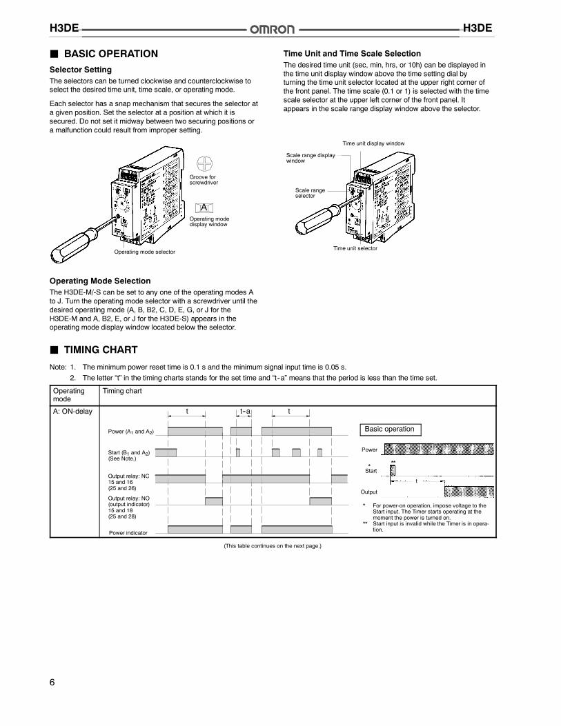
J BASIC OPERATIONSelector SettingThe selectors can be turned clockwise and counterclockwise toselect the desired time unit, time scale, or operating mode.
Each selector has a snap mechanism that secures the selector ata given position. Set the selector at a position at which it issecured. Do not set it midway between two securing positions ora malfunction could result from improper setting.
A
Operating mode selector
Groove forscrewdriver
Operating modedisplay window
Operating Mode SelectionThe H3DE-M/-S can be set to any one of the operating modes Ato J. Turn the operating mode selector with a screwdriver until thedesired operating mode (A, B, B2, C, D, E, G, or J for theH3DE-M and A, B2, E, or J for the H3DE-S) appears in theoperating mode display window located below the selector.
Time Unit and Time Scale SelectionThe desired time unit (sec, min, hrs, or 10h) can be displayed inthe time unit display window above the time setting dial byturning the time unit selector located at the upper right corner ofthe front panel. The time scale (0.1 or 1) is selected with the timescale selector at the upper left corner of the front panel. Itappears in the scale range display window above the selector.
Scale rangeselector
Scale range displaywindow
Time unit selector
Time unit display window
J TIMING CHART
Note: 1. The minimum power reset time is 0.1 s and the minimum signal input time is 0.05 s.2. The letter “t” in the timing charts stands for the set time and “t--a” means that the period is less than the time set.
Operatingmode
Timing chart
A: ON-delay t t
Power (A1 and A2)
Output relay: NC15 and 16(25 and 26)
Start (B1 and A2)(See Note.)
Output relay: NO(output indicator)15 and 18(25 and 28)
t--a
Power indicator
Power
Start
Output
t
Basic operation
* For power-on operation, impose voltage to theStart input. The Timer starts operating at themoment the power is turned on.
** Start input is invalid while the Timer is in opera-tion.
***
(This table continues on the next page.)

H3DEH3DE
7
Timing Chart — continued from previous page
Operatingmode
Timing chart
B:Repeat-cycle OFFstart
Basic operation
Power
Start
Output
t t t t
t t t--a t t t t--a
Power (A1 and A2)
Start (B1 and A2)(See Note.)
Power indicator
* For power-on operation, impose voltage to theStart input. The Timer starts operating at themoment the power is turned on.
** Start input is invalid while the Timer is in opera-tion.
Output relay: NC15 and 16(25 and 26)
Output relay: NO(output indicator)15 and 18(25 and 28)
***
B2:Repeat-cycle ONstart Basic operation
Power
Start
Output
t t t t
Power (A1 and A2)
Start (B1 and A2)(See Note.)
Power indicator
t tt t--a t t t--a
* For power-on operation, impose voltage to theStart input. The Timer starts operating at themoment the power is turned on.
** Start input is invalid while the Timer is in opera-tion.
Output relay: NC15 and 16(25 and 26)
Output relay: NO(output indicator)15 and 18(25 and 28)
***
C:SignalON/OFF-delay
Basic operation
Power
Start
Output
tt t t
Power (A1 and A2)
Start (B1 and A2)(See Note.)
Power indicator
t tt t t--a t--a
* Start input is invalid while the Timer is in opera-tion.
Output relay: NC15 and 16(25 and 26)
Output relay: NO(output indicator)15 and 18(25 and 28)
*
Note: The start input of the H3DE-M1 or H3DE-M2 model is activated by applying a voltage to B1 and A2 terminals.The voltage can be applied by turning on the contact between B1 and A1 (Refer to Terminal Arrangement).
(This table continues on the next page.)

H3DEH3DE
8
Timing Chart — continued from previous page
Operatingmode
Timing chart
D:SignalOFF-delay
Power (A1 and A2)
Start (B1 and A2)(See Note.)
Power indicator
tt t--a t--a t t--a
Basic operation
Power
Start
Output
t
* Start input is valid and re-triggerable while theTimer is in operation.
Output relay: NC15 and 16(25 and 26)
Output relay: NO(output indicator)15 and 18(25 and 28)
*
E: Interval
Power
Start
Output
t
Basic operation
t--at t
Power (A1 and A2)
Start (B1 and A2)(See Note.)
Power indicator
t t--a
* For power-on operation, impose voltage to theStart input. The Timer starts operating at themoment the power is turned on.
** Start input is valid and re-triggerable while theTimer is in operation.
Output relay: NC15 and 16(25 and 26)
Output relay: NO(output indicator)15 and 18(25 and 28)
***
G:SignalON/OFF-delay
Power (A1 and A2)
Start (B1 and A2)(See Note.)
Power indicator
Power
Start
Output
Basic operation
* Start input is valid and re-triggerable while theTimer is in operation.
t t t t
Output relay: NC15 and 16(25 and 26)Output relay: NO(output indicator)15 and 18(25 and 28)
*
J:One-shotoutput(ON delay)
Power (A1 and A2)
Start (B1 and A2)(See Note.)
Power indicator
Power
Start
Output
Basic operation
* For power-on operation, impose voltage to theStart input. The Timer starts operating at themoment the power is turned on.
** Start input is valid and re-triggerable while theTimer is in operation.
t t tt--a t--a
Approx.1±0.6 s(fixed)
Approx.1±0.6 s(fixed)
Approx.1±0.6 s(fixed)
t Approx. 1±0.6 s(fixed)
Output relay: NC15 and 16(25 and 26)Output relay: NO(output indicator)15 and 18(25 and 28)
***
Note: The start input of the H3DE-M1 or H3DE-M2 model is activated by applying a voltage to B1 and A2 terminals.The voltage can be applied by turning on the contact between B1 and A1 (Refer to Terminal Arrangement).

H3DEH3DE
9
DimensionsUnit: mm (inch)
J H3DE-MH3DE-S
75(2.95)
100(3.94)
Terminal block (black)
Surface color: 5Y7/1 (OMRON)
Output type selector switch (default setting: Time-limit output)
Terminal block (black)
5171
79(3.11)
36.9
12.7
7°
7°
22.5(0.89)
InstallationJ TERMINAL ARRANGEMENT
25/2115R1 R2
(See Note 1.)
18 16
18 16 A2
28/24 26/22
28/24 26/22
A1 15 25/21
25/2115R1 R2
(See Note 1.)
18 16
18 16 A2
B128/24 26/22
28/24 26/22
A1 15 25/21
H3DE-M1 H3DE-S1H3DE-M2 H3DE-S2
15R1
18 16
18 16 A2
B1
A1 15
15R1
18 16
18 16 A2
A1 15
(See Note 2.)
-------------------------------------------------
-------------------------------------------------
-------------------------------------------------
------------
-------------------------------------------------
-------------------------------------------------
-------------------------------------------------
------------
-------------------------------------------------
-------------------------------------------------
-------------------------------------------------
-------------------------------------------------
-------------------------------------------------
-------------------------------------------------
(See Note 2.) (See Note 2.) (See Note 2.)
Note: 1. The contact symbol for the H3DE is indicated with because it offers multiple operating modes and is different fromthe delayed contact for conventional timers.
2. DC supply voltage does not require the designation of polarity.3. The relay R2 can be set to either instantaneous or time-limit contact using the switch located on the bottom of the Timer.

H3DEH3DE
10
J INPUT CONNECTIONSThe inputs of the H3DE-M1/-M2 are voltage (voltage imposition or open) inputs.
No-Contact InputConnection to PNP output sensor. Contact Input
Sensor
A1B1Start
A2
24 VDC
A1B1Start
A2
Operates with PNP transistor ON Operates with relay ON
TimerTimer
No-Contact InputConnection to NPN output sensor.
(+)
(--)
Sensor
A1B1
A224 VDC
(+)
(--)
Operates with NPN transistor ON
Timer
Voltage Input Signal Levels
No-contact input 1. Transistor ONResidual voltage: 1 V max.; voltage between terminals B1 and A2 must be more than the rated“H-level” voltage (20.4 VDC min.)
2. Transistor OFFLeakage current: 0.01 mA max.; voltage between terminals B1 and A2 must be less than therated “L-level” voltage (2.4 VDC max.)
Contact input Use contacts that can adequately switch 0.1 mA at each voltage to be imposed. When thecontacts are ON or OFF, voltage between terminals B1 and A2 must be within the followingranges. When contacts are ON: 20.4 to 253 VAC/DC. When contacts are OFF: 0 to 2.4VAC/DC

H3DEH3DE
11
Accessories (Order Separately)
Mounting Track PFP-100N, PFP-50N PFP-100N2
L: Length
End Plate PFP-M Spacer PFP-S
4.5
15 25 25 25 25 *10 10
L
7.3±0.15
35±0.3 27±0.15
1
4.5
15 25 25 25 25 1510 10
L
35±0.3 27 24
16
29.2
1 1.5
M4 x 8pan headscrew
106.2
1.8
135.5
1.8
1.3
5
16(0.63)
12
10
34.8(1.37)
1 m50 cm1 m 39.37 in PFP-100N2
PFP-100N39.37 in19.69 in PFP-50N
50(1.97)
11.5(0.45)
35.3(1.39)
4.8(0.19)
44.3(1.74)
16.5(0.65)
Unit: mm (inch)
J DIMENSIONS
PrecautionsJ SETTING CHANGES
Note: Important: Do not change the time unit, time scale,operating mode, or output type selector switch while theTimer is in operation.
J MOUNTING AND REMOVALThe H3DE should be mounted as horizontally as possible.
When mounting the H3DE on a socket mounting track, hookportion (A) of the Timer to an edge of the track first, and thendepress the Timer in the direction of (B).
(A)
(B)
When removing the H3DE, pull out portion (C) with a flat-bladescrewdriver and remove the Timer from the mounting track.
(C) 30 mm (1.18 in) min.
Rail stopper
The H3DE can be mounted or removed easily if a distance of30 mm (1.18 in) or more is kept between the H3DE and the topsurface of other equipment located below the H3DE.

H3DEH3DE
12
J POWER SUPPLIESThe H3DE Series is provided with a transformerless powersupply system. An electric shock may be received if the inputterminal or the output type selector switch is touched while poweris being supplied.
Use the bar terminal for wiring the H3DE. Using a stranded-wireterminal may cause a short-circuit due to a stray wire enteringinto the Timer.
Both AC and DC power supplies can be connected to the powerinput terminals without regarding polarity.
With the H3DE only, a DC power supply must be connected tothe power input terminals as designated according to the polarityof the terminals.
A DC power supply can be connected if its ripple factor is 20% orless and the mean voltage is within the rated operating voltagerange of the Timer.
Connect the power supply voltage through a relay or switch insuch a way that the voltage reaches a fixed value at once or theTimer may not be reset or a timer error could result.
For the power supply of an input device, use an isolatingtransformer, of which the primary and secondary windings aremutually isolated and the secondary winding is not grounded.
H3DE Power supply
Circuit
Isolation transformer is required.Rectifiercircuit
Startinput
B1
A1
A2
J MOUNTING CLEARANCEIf the load current is continuously being supplied to the Timer fora long period of time, be sure to provide the mounting clearanceas shown in the figure below. If used under the conditions otherthan those specified below, the life of internal components maybe shortened due to an excessive rise in the internaltemperature.
t t
DIN track
t: Mounting clearance (mm)
H3DE H3DE H3DE
J SWITCHING CURRENT VS.AMBIENT TEMPERATURE(WHEN MOUNTING TWO OR MOREH3DE UNITS SIDE-BY-SIDE)
Ambienttem
perature(C)
0 1 2 3 4 5
70
60
50
40
30
20
Load current (A)
Mountingclearance: 0 mm
Mountingclearance: 5 mm
Mountingclearance: 10 mm
Maximum range ofoperating ambienttemperature
°
Mounting clearance:50 mm min.
Note: Measurement Condition: Input voltage of 230 VAC.

H3DEH3DE
13
J INPUT/OUTPUTRelationship between Input andPower Supply Circuits
Input circuit Power supplycircuit
AC/DCpowersupply
A1B1
A2
Since the input circuit and the power supply circuit are configuredindependently, the input circuit can be turned on or offirrespective of the on/off state of the power supply.It must be noted that a voltage equivalent to the power supplyvoltage is applied to the input circuit.
When connecting a relay or a transistor as an external signalinput device, pay attention to the following points to preventshort-circuiting due to a sneak current to the transformerlesspower supply.
If a relay or transistor is connected to two or more Timers, theinput terminals of those Timers must be wired properly so thatthey will not be different in phase or the terminals will beshort-circuited to one another (refer to the figures below).
IncorrectContact or transistor for external input signal
Correct
H3DE Power supplyB1
A1
A2
H3DEB1
A1
A2
Short-circuitcurrent
Contact or transistor for external input signal
H3DE Power supplyB1
A1
A2
H3DEB1
A1
A2
Short-circuitcurrent
Note: The H3DE Series is provided with a transformerless pow-er supply system.
J INPUT WIRESThe input wires must be as short as possible. If the floatingcapacity of wires exceeds 2,000 pF (approx. 17 m for cables with120 pF/m), the operation will be affected. Pay particular attentionwhen using shielded cables.
J VDE CONFORMANCEThe H3DE as a built-in timer conforms to VDE 0435/P2021provided that the following conditions are satisfied:
The output section of the H3DE is provided only with basicisolation. To ensure reinforced isolation required by the VDEstandards, provide supplementary basic isolation on the load sideconnected to the output.
The H3DE itself is designed according to the following:
• Overvoltage category III
• Pollution degree 2
The following facts are based on the above standards:• Operation parts on the front and bottom: Reinforced isolation
with clearance of 5.5 mm and creepage distance of 5.5 mmat 230 VAC
• Output: Basic isolation with clearance of 3 mm and creepagedistance of 3 mm at 230 VAC

H3DEH3DE
J ENVIRONMENTWhen using the Timer in an area with excess electronic noise,separate the Timer, wiring, and the equipment which generatesthe input signals as far as possible from the noise sources. Tofurther prevent electronic interference, shield the input signalwiring.
Organic solvents (such as paint thinner), as well as very acidic orbasic solutions can damage the outer casing of the Timer.
Do not use the Timer in places where it is exposed to dust,corrosive gas, or direct sunlight.
When storing the Timer, make sure that the ambient temperatureand humidity are within the rated values. Leave the Timer atroom temperature for at least three hours before using the Timerif it has been stored at an ambient temperature of --10°C orbelow.
J RELAY LIFE EXPECTANCYBuilt-in relay for the H3DE: G6RN; 50,000 operations min.(8 A at 250 VAC, resistive load at 360 operations/h.)
Cat. No. GC TMCN1 3/02 Specifications subject to change without notice. Printed in U.S.A.
OMRON ELECTRONICS LLCOne East Commerce DriveSchaumburg, IL 60173
NOTE: DIMENSIONS SHOWN ARE IN MILLIMETERS. To convert millimeters to inches divide by 25.4.
1-800-55-OMRON
OMRON CANADA, INC.885 Milner AvenueScarborough, Ontario M1B 5V8
416-286-6465
R
OMRON ON--LINEGlobal -- http://www.omron.comUSA -- http://www.omron.com/oeiCanada -- http://www.omron.com/oci