Embed Size (px)
Citation preview
International Research Journal of Engineering and Technology (IRJET) e-ISSN: 2395 -0056
Volume: 03 Issue: 06 | June-2016 www.irjet.net p-ISSN: 2395-0072
© 2016, IRJET | Impact Factor value: 4.45 | ISO 9001:2008 Certified Journal | Page 880
Multifocus and multispectral image fusion based on pixel features
using discrete cosine harmonic wavelet transformed and
morphological filter
Shikha Dhyani1, R P Singh2
1M-tech scholar, Department of ECE,BTKIT Dwarahat,Almora-263653,Uttrakhand,India 2Assistant Professor, Department of ECE, BTKIT Dwarahat,Almora-263653,Uttrakhand,India
---------------------------------------------------------------------***---------------------------------------------------------------------
Abstract - The energy compaction and multi-resolution
properties of wavelets have made the image fusion successful
in combining important features such as edges and textures
from source images without introducing any artifacts for
context enhancement and situational awareness. The wavelet
transform is visualized as a convolution of wavelet filter
coefficients with the image under consideration and is
computationally intensive. The advent of lifting-based
wavelets has reduced the computations but at the cost of
visual quality and performance of the fused image. To retain
the visual quality and performance of the fused image with
reduced computations, a discrete cosine harmonic wavelet
(DCHWT) based image fusion followed by morphological
filter using top hat transform is proposed. . The performance of
Enhanced DCHWT is compared with DCHWT image give
remarkable differences.
Key Words: Image Fusion, Pixel Significance, Multifocus,
Multisensor, Discrete Wavelet Transform, Harmonic
Wavelet Transform, Discrete Cosine Harmonic Wavelet
Transform.
1. INTRODUCTION
The concept of data fusion goes back to the 1950’s and
1960’s, with the search for practical methods of
merging images from various sensors to provide a
composite image which could be used to better identify
natural and manmade objects . Fusion is a process
which can be used to improve excellence of
information from a set of images. By the process of
image fusion the good information from each of the
given images is fused together to form resultant image
whose quality is superior to any of input images [1].
There are important requirements for image fusion
process[4]. The fused image should reserve all relevant
information from the input images. -Image fusion
should not introduce relics which can lead to wrong
diagnosis. Image fusion techniques have been used in
various application areas including remote sensing,
biomedical imaging, and multi-exposure multi-focus
image integration and advance in large number of
sophisticated medical imaging modalities like:
Magnetic Resonance Imaging (MRI), Computed
Tomography (CT), Positron Emission Tomography
(PET), Ultrasound, X-ray, Single Positron Emission
Computed Tomography (SPECT), Electrocardiography
(ECG) etc. have added to the visual response from these
devices in terms of interpretation and diagnostic
analysis [6],[7]. In the field of remote sensing, medical
imaging and machine vision the multi-sensor data may
have multiple images of the same scene providing
different information. As optical lenses in charged
coupled devices have limited depth of focus, it is not
possible to have a single image that contains all the
information of objects in the image, so image fusion is
International Research Journal of Engineering and Technology (IRJET) e-ISSN: 2395 -0056
Volume: 03 Issue: 06 | June-2016 www.irjet.net p-ISSN: 2395-0072
© 2016, IRJET | Impact Factor value: 4.45 | ISO 9001:2008 Certified Journal | Page 881
required. There are two groups into which image
fusion methods are divided, namely spatial domain
fusion method and Transform domain fusion method.
Spatial domain fusion method will directly deal with
pixels of input images. In Transform domain fusion
method image is first transformed into frequency
domain. Use of the Simple primitive technique will not
improve good fused image in terms of performance
parameter like peak signal to noise ratio (PSNR),
Normalized correlation (NC), and Mean square error
(MSE). Recently, Discrete Wavelet Transform (DWT)
and Principal Component Analysis, Morphological
processing and Combination of DWT with PCA and
Morphological techniques have been prevalent fusion
of image[2][3][5].
1.1 Discrete Cosine transform based Image Fusion
DCT is a process to modify a signal into elementary
frequency components. DCT is a closely related to discrete
Fourier transform (DFT), using the DCT a signal is
categorized into its basic frequency components. When we
use DCT on X*Y sized matrix, the 2D-DCT extract the energy
information of the image and then it will focus on some
specific features located in the upper left Corner of the
outcome real-valued X*Y DCT matrix The workings of DCT
coefficients return the average energy of pixel blocks
whereas the AC components return the intensity of image.
As DCT separates an image hooked on discrete blocks of
pixels of differing significance or weight age in an image so
we can say that DCT is a flossy technique [9].
Discrete cosine transform is defined [9] as equation (7).
(7)
1.2 Discrete Wavelet Transform based Image Fusion
We can calculate Wavelet coefficients by a wavelet
transform which shows changes according to time interval at
a specific resolution. Taking the time interval makes it easy
to calculate and remove the noise from image. The term
wavelet transform is explained as decomposition of the data
or the image into wavelet coefficients, comparing the detail
coefficients with a given threshold value, and shrinking these
coefficients close to zero to take away the effect of noise in
the data. The image is reconstructed from the modified
coefficients which are known as the inverse discrete wavelet
transforms [10]. DWT transformations convert the image
into four different frequency sub band as LL, LH , HL and HH
as figure 1. Where range of frequency is represented as
LL<LH<HL< HH. The feature or characteristics of image is
represented by low frequency coefficients or LL sub band so
LL frequency sub band is used for image fusion [11].
2. Discrete cosine harmonic wavelet transform
based Image Fusion
In DCT, the generation of an even symmetric periodic
sequence removes the discontinuity as the symmetric signal
moves from one period to the next period smoothly. As a
result, like the DFT, the DCT does not suffer from leakage
effects or Gibbs ripple.
For a real symmetric signal xs(t) and a real symmetric
wavelet function ψs(t), Eq. can be written as
International Research Journal of Engineering and Technology (IRJET) e-ISSN: 2395 -0056
Volume: 03 Issue: 06 | June-2016 www.irjet.net p-ISSN: 2395-0072
© 2016, IRJET | Impact Factor value: 4.45 | ISO 9001:2008 Certified Journal | Page 882
where Xs(ω) ands(ω) are the cosine transforms of xs(t) and
wavelet function ψs(t), respectively. Wc(a, b) is the wavelet
transform in the cosine domain rather than the Fourier
domain.
The corresponding wavelet ψs(t)in time domain becomes
In DCHWT, the signal is decomposed by grouping the DCT
coefficients in a way similar to that of DFT coefficients except
for the conjugate operation in placing the coefficients
symmetrically (as DCT is rea)l. Further, symmetric
placement is also not necessary due to the very definition of
DCT. The inverse DCT (IDCT) of these groups results in
discrete cosine harmonic wavelet coefficients (DCHWCs).
The DCT of these processed sub-bands (groups of DCHWCs)
results in sub-band DCT coefficients, which are repositioned
in their corresponding positions to recover the overall DCT
spectrum at the original sampling rate. Akin to Fourier-
based HWT, DCHWT also has similar advantages like (a)
flexibility of built-in decimation and interpolation
operations, (b) no band-limiting and image-rejection filters
are necessary, (c) availability of fast algorithms based on the
DCT. In addition, DCHWT is computationally simpler than
the Fourier-based HWT as it involves only real operations
and hence it is even more computationally simpler than
convolution.
Gray‐scale morphological filter
basic operations of dilation, erosion, opening, and closing to
gray-scale images. f(x, y) is a grey-scale image and b(x, y) is a
structuring element and both functions are discrete. The
structuring elements are used to examine a given image for
specific properties. The dilation of f by a flat structuring
element b at any location (x, y) is defined as the maximum
value of the image in the window outlined by b ˆ when the
origin of b ˆ is at f(x,y)
The erosion of f by a flat structuring element b at any
location (x, y) is defined as the minimum value of the image
in the region coincident with b when the origin of b is at (x,
y). Therefore, the erosion at (x, y) of an image f by a
structuring element b is given by:
the opening of the image f by structuring element b is
defined as the erosion of f by b followed by a illation of the
result with b:
Similarly, the closing of f by b is
top‐hat and bottom‐hat transformations One principal
application of these transforms is in removing objects from
an image by using an SE in the opening and closing that does
not fit the objects to be removed. The difference then yields
image with only the removed objects. The top-hat is used for
light objects on a dark background and the bottom-hat for
dark objects on a light background. An important use of top-
hat transformation is in correcting the effects of non-uniform
illumination. Let be a grayscale image,
mapping points from a Euclidean space E (such as R2 or Z2)
into the real line. Let be a grayscale structuring
element. Then, the white top-hat transform of f is given by:
,
The black top-hat transform of f (sometimes called the
bottom-hat transform [1] ) is given by:
International Research Journal of Engineering and Technology (IRJET) e-ISSN: 2395 -0056
Volume: 03 Issue: 06 | June-2016 www.irjet.net p-ISSN: 2395-0072
© 2016, IRJET | Impact Factor value: 4.45 | ISO 9001:2008 Certified Journal | Page 883
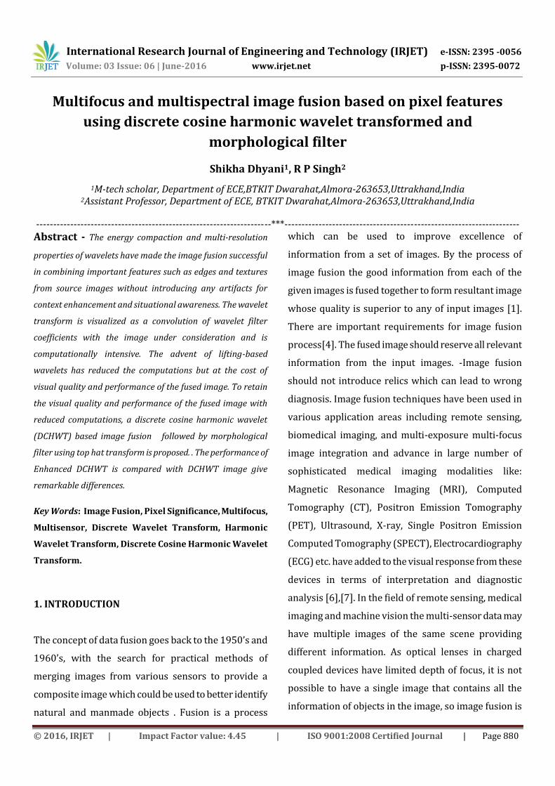
Algorithm:
In proposed method after preprocessing of images ,images
are fused using DCHWT where the signal is decomposed by
grouping the DCT coefficients in a way similar to that of DFT
coefficients except for the conjugate operation in placing the
coefficients symmetrically (as DCT is real).along with
performance evaluation of the fused image .after fusion
image post processing has to be done in spectral domain
using top hat transform for better performance parameter of
images.
3. RESULT
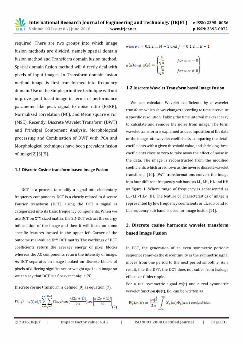
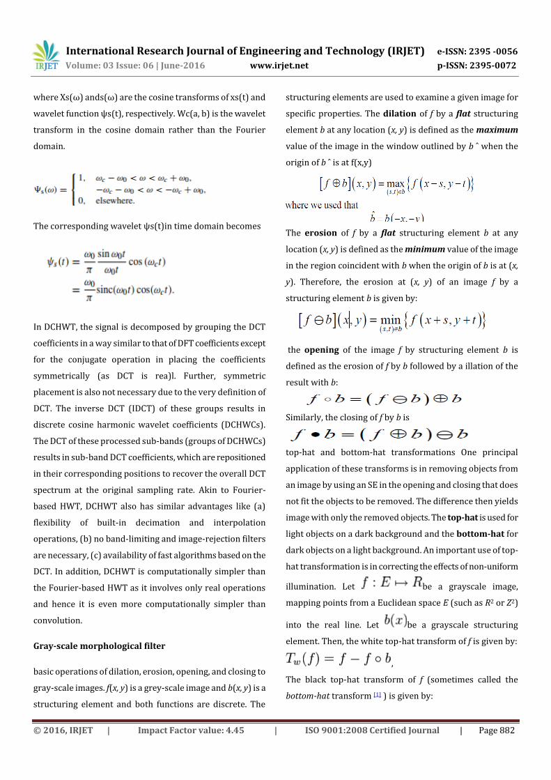
Test Image1: Girl Image
Image to be Fused
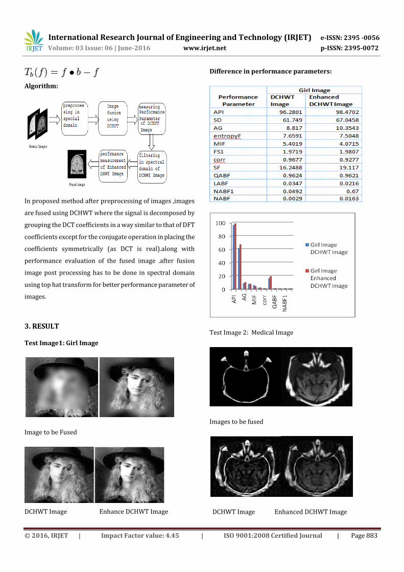
DCHWT Image Enhance DCHWT Image
Difference in performance parameters:
Test Image 2: Medical Image
Images to be fused
DCHWT Image Enhanced DCHWT Image

International Research Journal of Engineering and Technology (IRJET) e-ISSN: 2395 -0056
Volume: 03 Issue: 06 | June-2016 www.irjet.net p-ISSN: 2395-0072
© 2016, IRJET | Impact Factor value: 4.45 | ISO 9001:2008 Certified Journal | Page 884
Difference in performance parameters:
Test Image3: Doctor image
Images to be Fused
DCHWT Image Enhanced DCHWT Image
Difference in performance parameters:
Test Image4: Disk image
Image to be Fused
DCHWT Image Enhanced DCHWT Image

International Research Journal of Engineering and Technology (IRJET) e-ISSN: 2395 -0056
Volume: 03 Issue: 06 | June-2016 www.irjet.net p-ISSN: 2395-0072
© 2016, IRJET | Impact Factor value: 4.45 | ISO 9001:2008 Certified Journal | Page 885
Difference in performance parameters:
Test Image 5: Gun Image
Images to be fused
DCHWT Image Enhanced DCHWT Image
Difference in performance parameters:
3. CONCLUSIONS
For better result of performance parameter of fused image
tophat transform followed by DCHWT is good as compare to
DCHWT only.
REFERENCES
[1] Sweta K. Shah, Prof. D.U. Shah “Comparative Study of
Image Fusion Techniques based on Spatial and Transform
Domain,” in International Journal of Innovative Research in
Science, Engineering and Technology , Vol. 3, Issue 3, March
2014.
[2] Yufeng Zheng, Edward A. Essock and Bruce C. Hansen,
“An Advanced Image Fusion Algorithm Based on Wavelet
International Research Journal of Engineering and Technology (IRJET) e-ISSN: 2395 -0056
Volume: 03 Issue: 06 | June-2016 www.irjet.net p-ISSN: 2395-0072
© 2016, IRJET | Impact Factor value: 4.45 | ISO 9001:2008 Certified Journal | Page 886
Transform – Incorporation with PCA and Morphological
Processing”
[3] Shrivsubramani Krishnamoorthy, K P Soman,“
Implementation and Comparative Study of Image Fusion
Algorithms” .International Journal of Computer Applications
(0975 – 8887) Volume 9– No.2, November 2010.
[4] A.Ufade, M.Kawade, “Comparision of spatial domain and
transform domain image fusion technique for restoration of
blur images”, International Conference on Recent Trends in
engineering & Technology, 2013.
[5] Jonathon Shlens, “A Tutorial on Principal Component
Analysis”. Center for Neural Science, New York University
New York City, NY 10003-6603 and Systems Neurobiology
Laboratory, Salk Insitute for Biological Studies La Jolla, CA
92037.
[6] Rania Hassen, Zhou Wang, and Magdy M. A. Salama,
“Objective Quality Assessment for Multiexposure Multifocus
Image Fusion.” IEEE transactions on image processing, vol.
24, no. 9, september 2015.
[7] Vikrant Bhateja, Member, Himanshi Patel, Abhinav
Krishn, Akanksha Sahu, and Aimé Lay-Ekuakille, “Multimodal
Medical Image Sensor Fusion Framework Using Cascade of
Wavelet and Contourlet Transform Domains.”ieee sensors
journal, vol. 15, no. 12, december 2015.
[8] Lewis, John J., Robert J. O’Callaghan, Stavri G. Nikolov,
David R. Bull, and Nishan Canagarajah. "Pixel-and region-
based image fusion with complex wavelet" Information
fusion, Vol.8, No. 2, pp:119-130, 2007.
[9]Kusum Rani1, Reecha Sharma2, “Study of Different Image
fusion Algorithm.” International Journal of Emerging
Technology and Advanced Engineering, Volume 3, Issue 5,
May 2013.
[10]Yong Yang, Member, Song Tong, Shuying Huang, and Pan
Lin, “Multifocus Image Fusion Based on NSCT and Focused
Area Detection” IEEE Sensors Journal, Vol. 15, No. 5, May
2015.
[11]Dosodia, Priya, Amarjeet Poonia, Sandeep K. Gupta, and
Shubh Lakshmi Agrwal. "New Gabor-DCT Feature Extraction
Technique for Facial Expression Recognition."In Fifth
International Conference on Communication Systems and
Network Technologies (CSNT), pp. 546-549. IEEE, 2015.


![A simple and efficient algorithm for multifocus image ... · two multifocus images. In the method suggested by Yang et al. [7], an impulse function is defined at first to describe](https://img.dokumen.tips/doc/110x75/5f0520a87e708231d411679b/a-simple-and-eficient-algorithm-for-multifocus-image-two-multifocus-images.jpg)

![Multi-focus Image Fusion Based on Muti-schemevigir.missouri.edu/~gdesouza/Research/Conference... · decomposition method [1, 2] and wavelet image fusion method. Wavelet image fusion](https://img.dokumen.tips/doc/110x75/5f610cf2ca7f86655445691a/multi-focus-image-fusion-based-on-muti-gdesouzaresearchconference-decomposition.jpg)