Embed Size (px)
Citation preview

MULTIFIX 4 USERS MANUAL Version 1.05
© Copyright 2004 Fugro Ltd
Master Register Number: REFJ500A
Dated: March 2004
Issue No: 5

MultiFix 4 Users' Manual Amendment Record Sheet
AMENDMENT RECORD SHEET
Issue No Date Revised Section(s) Revised Page No(s) Authorised
1 Apr 2003 N/A N/A MK
2 June 2003 N/A N/A TH
3 Sept 2003 N/A N/A MK
4 Dec 2003 N/A N/A MK
5 Mar 2004 N/A N/A PAF
REFJ500A - Issue 5 March 2004 Page i
MULTIFIX 4 USER MANUAL Contents
CONTENTS Page No
AMENDMENT RECORD SHEET ............................................................................................................. i CONTENTS ................................................................................................................................... ii TABLE OF FIGURES............................................................................................................................. xii 1. INTRODUCTION.......................................................................................................1 2. ZERO APPLICATION RESUME ...............................................................................2 3. SOFTWARE INSTALLATION ...................................................................................4
3.1. ZERO SUITE PROGRAMS.......................................................................................4 3.2. DONGLE DRIVERS ..................................................................................................9 3.3. DIGIBOARD DRIVERS ...........................................................................................11 3.4. PRE-CONFIGURATION..........................................................................................13
3.4.1. Comms Profile ..........................................................................................13 3.4.2. Output Pre-Selection ................................................................................13
4. MULTIFIX 4 .............................................................................................................15 4.1. INTRODUCTION.....................................................................................................15 4.2. CONFIGURATION ..................................................................................................17
4.2.1. SkyFix Single Frequency..........................................................................17 4.2.2. SkyFix-XP / Premier Dual - Frequency ....................................................18 4.2.3. HARDWARE REQUIREMENT.................................................................19 4.2.4. GPS RECEIVER CONFIGURATIONS.....................................................21
4.2.4.1. Ashtech (Thales Navigation) Receivers ........................................21 4.2.4.1.1. Configuration from within MultiFix .......................................21 4.2.4.1.2. Ashtech Evaluate Configuration ..........................................21 4.2.4.1.3. Ashtech Z-Family.................................................................23 4.2.4.1.4. Ashtech DG16 .....................................................................24 4.2.4.1.5. Ashtech G12........................................................................25 4.2.4.1.6. Ashtech GG24 .....................................................................26
4.2.4.2. Trimble Receiver Configuration .....................................................27 4.2.4.2.1. Trimble BD112.....................................................................27 4.2.4.2.2. Trimble DSM........................................................................27 4.2.4.2.3. Trimble DSM212..................................................................27 4.2.4.2.4. Trimble SK8.........................................................................28 4.2.4.2.5. Trimble MS750 ....................................................................28 4.2.4.2.6. Trimble BD750.....................................................................30 4.2.4.2.7. Trimble 5700........................................................................30 4.2.4.2.8. Trimble 4000DS...................................................................33 4.2.4.2.9. Trimble 4000 SSE ...............................................................34 4.2.4.2.10. Trimble 4000 SSi ...........................................................36
4.2.4.3. NovAtel Receivers .........................................................................38 4.2.4.3.1. NovAtel Millennium..............................................................38 4.2.4.3.2. NovAtel OEM4.....................................................................41
REFJ500A - Issue 5 March 2004 Page ii

MULTIFIX 4 USER MANUAL Contents
4.2.5. MultiFix 4 Files..........................................................................................44 4.2.6. TO RUN MULTIFIX 4 ...............................................................................45
4.3. REAL TIME OPERATION .......................................................................................46 4.3.1. THE TOOL BAR .......................................................................................49 4.3.2. FILE ..........................................................................................................51
4.3.2.1. New................................................................................................51 4.3.2.2. Open ..............................................................................................51
4.3.2.2.1. Save.....................................................................................52 4.3.2.3. Save As..........................................................................................52 4.3.2.4. Exit .................................................................................................52
4.3.3. CONFIGURE ............................................................................................53 4.3.3.1. IO ...................................................................................................53
4.3.3.1.1. Comm ..................................................................................53 4.3.3.1.2. Sockets................................................................................54
4.3.3.2. GPS Receiver ................................................................................58 4.3.3.3. SkyFix Decoder .............................................................................59
4.3.3.3.1. New......................................................................................60 4.3.3.3.2. Editing and Deleting ............................................................62
4.3.3.4. Calculations ...................................................................................63 4.3.3.4.1. Settings................................................................................63 4.3.3.4.2. SkyFix-XP............................................................................65 4.3.3.4.3. New Calculation...................................................................67 4.3.3.4.4. Editing and Deleting ............................................................68
4.3.3.5. Output ............................................................................................69 4.3.3.5.1. Standard Outputs ................................................................71 4.3.3.5.2. Approved NMEA Sentence Outputs....................................72 4.3.3.5.3. UTM Outputs .......................................................................76 4.3.3.5.4. Editing and Deleting ............................................................76
4.3.3.6. P2/94 Output..................................................................................77 4.3.4. LOGGING.................................................................................................79
4.3.4.1. Zero................................................................................................79 4.3.4.1.1. Edit.......................................................................................79 4.3.4.1.2. Starting, Stopping and Pausing...........................................80
4.3.4.2. Rinex..............................................................................................81 4.3.4.2.1. Edit.......................................................................................82 4.3.4.2.2. Starting, Stopping and Pausing...........................................83
4.3.5. ACTION ....................................................................................................84 4.3.5.1. Restart Sockets .............................................................................84 4.3.5.2. Collect Almanac.............................................................................84 4.3.5.3. Update SkyFix................................................................................85 4.3.5.4. Reset SkyFix-XP Filter...................................................................86 4.3.5.5. Configure TSIP ..............................................................................86
4.3.5.5.1. Default TSIP Configuration..................................................86 4.3.5.5.2. Advanced TSIP Configuration .............................................87
REFJ500A - Issue 5 March 2004 Page iii

MULTIFIX 4 USER MANUAL Contents
4.3.5.6. Configure GPS Receiver ...............................................................88 4.3.5.6.1. Default Receiver configuration ............................................88 4.3.5.6.2. Advanced Receiver configuration........................................88
4.3.5.7. SV Status .......................................................................................89 4.3.6. VIEW.........................................................................................................90
4.3.6.1. Files ...............................................................................................92 4.3.6.2. Work Area......................................................................................92 4.3.6.3. Input / Output .................................................................................93
4.3.6.3.1. Status...................................................................................93 4.3.6.3.2. Sockets................................................................................94 4.3.6.3.3. Datagrams ...........................................................................94 4.3.6.3.4. Scroller ................................................................................95
4.3.6.4. GPS ...............................................................................................97 4.3.6.4.1. Receiver ..............................................................................97 4.3.6.4.2. Measurements.....................................................................98 4.3.6.4.3. Scintillation Meter ................................................................99 4.3.6.4.4. Code Carrier Filter (CCF) ..................................................100 4.3.6.4.5. Iono Filter...........................................................................105 4.3.6.4.6. Ephemeris .........................................................................106 4.3.6.4.7. Almanac.............................................................................106 4.3.6.4.8. Clock..................................................................................109
4.3.6.5. Corrections...................................................................................110 4.3.6.5.1. Orbit Data ..........................................................................110 4.3.6.5.2. DGPS Data........................................................................112 4.3.6.5.3. SkyFix Decoder .................................................................117 4.3.6.5.4. Latency ..............................................................................119 4.3.6.5.5. Type 16..............................................................................123 4.3.6.5.6. SkyFix Beams....................................................................124
4.3.6.6. Calculations .................................................................................124 4.3.6.6.1. Status.................................................................................124 4.3.6.6.2. Positions ............................................................................127 4.3.6.6.3. XP Offsets .........................................................................128 4.3.6.6.4. Offsets ...............................................................................129 4.3.6.6.5. Residuals...........................................................................130 4.3.6.6.6. UKOAA Stats.....................................................................132 4.3.6.6.7. Time Series Plots ..............................................................135
4.3.6.7. Event Log.....................................................................................140 4.3.7. OPTIONS................................................................................................142
4.3.7.1.1. Lock ...................................................................................142 4.3.7.2. Colour ..........................................................................................142 4.3.7.3. Hide Tool Bar...............................................................................143 4.3.7.4. Trial Point Warning ......................................................................143 4.3.7.5. Rinex............................................................................................143 4.3.7.6. Type 16 Alert................................................................................144
REFJ500A - Issue 5 March 2004 Page iv
MULTIFIX 4 USER MANUAL Contents
4.3.7.7. Event Logger................................................................................144 4.3.8. TOOLS....................................................................................................145
4.3.8.1. Position Viewer Wizard................................................................145 4.3.8.2. Save Almanac to File...................................................................147
4.3.9. WINDOWS..............................................................................................148 4.3.9.1. Tile ...............................................................................................148 4.3.9.2. Close All.......................................................................................148 4.3.9.3. The Open Windows .....................................................................148
4.3.10. HELP ......................................................................................................149 4.3.10.1. Help..............................................................................................149 4.3.10.2. Dongle..........................................................................................149 4.3.10.3. Performance ................................................................................150 4.3.10.4. About............................................................................................150
4.4. MULTIFIX 4 REPLAY............................................................................................151 4.4.1. Replay options ........................................................................................152
5. SKYLINK ...............................................................................................................154 5.1. INTRODUCTION...................................................................................................154 5.2. CONFIGURATION ................................................................................................158
5.2.1. HARDWARE INTERCONNECTION.......................................................158 5.2.2. HARDWARE REQUIREMENT...............................................................160 5.2.3. GPS RECEIVER CONFIGURATIONS...................................................161
5.2.3.1. Ashtech (Thales Navigation) Receivers ......................................161 5.2.3.1.1. Configuration from within MultiFix .....................................161 5.2.3.1.2. Ashtech Evaluate Configuration ........................................161
5.2.3.2. Trimble Receiver Configuration ...................................................163 5.2.3.2.1. Trimble 4000DS AND 4000SSE/SSI.................................163 5.2.3.2.2. Trimble MS750 ..................................................................165
5.2.4. SKYLINK FILES......................................................................................167 5.2.5. TO RUN SKYLINK..................................................................................167
5.3. REAL TIME OPERATION .....................................................................................168 5.3.1. FILE ........................................................................................................170
5.3.1.1. New..............................................................................................170 5.3.1.2. Open ............................................................................................170 5.3.1.3. Save.............................................................................................171 5.3.1.4. Save As........................................................................................171 5.3.1.5. Exit ...............................................................................................171
5.3.2. CONFIGURE ..........................................................................................172 5.3.2.1. IO .................................................................................................172
5.3.2.1.1. Comm ................................................................................172 5.3.2.1.2. Sockets..............................................................................173
5.3.2.2. GPS Receiver ..............................................................................177 5.3.2.3. RTCM...........................................................................................179
5.3.2.3.1. New....................................................................................179 5.3.2.3.2. Editing and Deleting ..........................................................181
REFJ500A - Issue 5 March 2004 Page v

MULTIFIX 4 USER MANUAL Contents
5.3.2.4. Outputs ........................................................................................182 5.3.3. ACTION ..................................................................................................183
5.3.3.1. Restart Sockets ...........................................................................183 5.3.3.2. Configure Ashtech .......................................................................183
5.3.3.2.1. Default Ashtech configuration ...........................................183 5.3.3.2.2. Advanced Ashtech configuration.......................................184
5.3.4. VIEW.......................................................................................................185 5.3.4.1. Input / Output ...............................................................................187
5.3.4.1.1. Status.................................................................................187 5.3.4.1.2. Sockets..............................................................................188 5.3.4.1.3. Datagrams .........................................................................188 5.3.4.1.4. Scroller ..............................................................................188
5.3.4.2. GPS .............................................................................................191 5.3.4.2.1. Receiver ............................................................................191 5.3.4.2.2. Measurements...................................................................192 5.3.4.2.3. Code Carrier Filter (CCF) ..................................................193 5.3.4.2.4. Iono Filter...........................................................................197 5.3.4.2.5. Clock..................................................................................198 5.3.4.2.6. Ephemeris .........................................................................199
5.3.4.3. RTCM...........................................................................................200 5.3.4.3.1. Constellation......................................................................200 5.3.4.3.2. Latency ..............................................................................201 5.3.4.3.3. Station ...............................................................................203 5.3.4.3.4. Performance ......................................................................205 5.3.4.3.5. SkyFix Decoder .................................................................206
5.3.5. OPTIONS................................................................................................207 5.3.5.1. Lock .............................................................................................207 5.3.5.2. Colour ..........................................................................................207 5.3.5.3. Hide Tool Bar...............................................................................208
5.3.6. WINDOWS..............................................................................................209 5.3.6.1. Tile ...............................................................................................209 5.3.6.2. Close All.......................................................................................209 5.3.6.3. The Open Windows .....................................................................209
5.3.7. HELP ......................................................................................................210 5.3.7.1. Dongle..........................................................................................210 5.3.7.2. Performance ................................................................................210 5.3.7.3. About............................................................................................211
6. RECEIVER VERIFY (RxV)....................................................................................212 6.1. INTRODUCTION...................................................................................................212
6.1.1. RXV APPLICATIONS .............................................................................213 6.1.2. Operational Theory.................................................................................214
6.2. CONFIGURATION ................................................................................................215 6.2.1. HARDWARE REQUIREMENTS.............................................................216 6.2.2. COMMUNICATIONS NETWORK...........................................................217
REFJ500A - Issue 5 March 2004 Page vi

MULTIFIX 4 USER MANUAL Contents
6.2.3. RXV FILES .............................................................................................218 6.2.4. TO RUN RXV..........................................................................................219 6.2.5. MULTIFIX CONFIGURATION................................................................219 6.2.6. INTERFACING TO PDS 2000 LITE .......................................................219
6.3. REAL TIME OPERATION .....................................................................................220 6.3.1. FILE ........................................................................................................222
6.3.1.1. New..............................................................................................222 6.3.1.2. Open ............................................................................................222 6.3.1.3. Save.............................................................................................223 6.3.1.4. Save As........................................................................................223 6.3.1.5. Exit ...............................................................................................223
6.3.2. CONFIGURE ..........................................................................................224 6.3.2.1. IO .................................................................................................224
6.3.2.1.1. Comm ................................................................................224 6.3.2.1.2. Sockets..............................................................................225
6.3.2.2. GPS Receiver ..............................................................................229 6.3.2.2.1. New Receiver ....................................................................229 6.3.2.2.2. Editing and Deleting ..........................................................230
6.3.2.3. Rx Position Input..........................................................................231 6.3.2.4. Calculation ...................................................................................232
6.3.2.4.1. Receivers...........................................................................232 6.3.2.4.2. Parameters ........................................................................232
6.3.2.5. Receiver Output...........................................................................234 6.3.3. LOGGER ................................................................................................235
6.3.3.1. Edit...............................................................................................235 6.3.3.2. Starting, Stopping and Pausing ...................................................236
6.3.4. ACTION ..................................................................................................237 6.3.4.1. Restart Sockets ...........................................................................237
6.3.5. VIEW.......................................................................................................238 6.3.5.1. Input / Output ...............................................................................240
6.3.5.1.1. Status.................................................................................240 6.3.5.1.2. Sockets..............................................................................241 6.3.5.1.3. Datagrams .........................................................................241 6.3.5.1.4. Scroller ..............................................................................242
6.3.5.2. GPS .............................................................................................243 6.3.5.2.1. Synch.................................................................................243 6.3.5.2.2. Clock..................................................................................243 6.3.5.2.3. Almanac.............................................................................245 6.3.5.2.4. Ephemeris .........................................................................247 6.3.5.2.5. Constellation......................................................................248
6.3.5.3. Status...........................................................................................249 6.3.5.3.1. Status.................................................................................249
6.3.6. OPTIONS................................................................................................251 6.3.7. Lock ........................................................................................................251
REFJ500A - Issue 5 March 2004 Page vii

MULTIFIX 4 USER MANUAL Contents
6.3.8. Colour .....................................................................................................251 6.3.9. Hide Tool Bar..........................................................................................252 6.3.10. WINDOWS..............................................................................................252
6.3.10.1. Tile ...............................................................................................252 6.3.10.2. Close All.......................................................................................252 6.3.10.3. The Open Windows .....................................................................252
6.3.11. HELP ......................................................................................................254 6.3.11.1. Dongle..........................................................................................254 6.3.11.2. Performance ................................................................................255 6.3.11.3. About............................................................................................255
6.4. RxV REPLAY.........................................................................................................256 7. SOCCER ...............................................................................................................257
7.1. INTRODUCTION...................................................................................................257 7.2. CONFIGURATION ................................................................................................258
7.2.1. HARDWARE REQUIREMENTS.............................................................258 7.2.2. TO RUN SOCCER..................................................................................258
7.3. REAL TIME OPERATION .....................................................................................259 7.3.1. FILE ........................................................................................................259
7.3.1.1. New..............................................................................................259 7.3.1.2. Open ............................................................................................259 7.3.1.3. Save.............................................................................................260 7.3.1.4. Save As........................................................................................260 7.3.1.5. Exit ...............................................................................................260
7.3.2. CONFIG..................................................................................................261 7.3.2.1. IO .................................................................................................261
7.3.2.1.1. Comm ................................................................................261 7.3.2.1.2. Sockets..............................................................................262
7.3.2.2. Ribbon..........................................................................................266 7.3.2.2.1. New....................................................................................266
7.3.2.3. Test logger ...................................................................................266 7.3.2.3.1. New....................................................................................267
7.3.3. LOGGER ................................................................................................267 7.3.3.1. Edit...............................................................................................268 7.3.3.2. Starting, Stopping and Pausing ...................................................269
7.3.4. ACTION ..................................................................................................270 7.3.4.1. Restart Sockets ...........................................................................270
7.3.5. VIEW.......................................................................................................270 7.3.5.1. IO Status ......................................................................................272 7.3.5.2. Sockets ........................................................................................273 7.3.5.3. Datagram Status..........................................................................273 7.3.5.4. Scroller.........................................................................................274
7.3.5.4.1. RTCM Input .......................................................................275 7.3.5.4.2. Output Strings....................................................................275
7.3.5.5. Text Logging ................................................................................275
REFJ500A - Issue 5 March 2004 Page viii
MULTIFIX 4 USER MANUAL Contents
7.3.6. OPTIONS................................................................................................276 7.3.6.1. Lock .............................................................................................276 7.3.6.2. Colour ..........................................................................................276 7.3.6.3. Hide Tool Bar...............................................................................277
7.3.7. WINDOWS..............................................................................................277 7.3.7.1. Tile ...............................................................................................277 7.3.7.2. Close All.......................................................................................277 7.3.7.3. The Open Windows .....................................................................277
7.3.8. HELP ......................................................................................................279 7.3.8.1. Dongle..........................................................................................279 7.3.8.2. Performance ................................................................................280 7.3.8.3. About............................................................................................280
7.4. SOCCER AND MULTIFIX 4 ..................................................................................281 8. LOG PUMP............................................................................................................284
8.1. INTRODUCTION...................................................................................................284 8.2. CONFIGURATION ................................................................................................285
8.2.1. HARDWARE INTERCONNECTION.......................................................285 8.2.2. HARDWARE REQUIREMENT...............................................................286 8.2.3. LOG PUMP FILES..................................................................................286
8.3. REAL TIME OPERATION .....................................................................................287 8.3.1. FILE ........................................................................................................289
8.3.1.1. New..............................................................................................289 8.3.1.2. Open ............................................................................................289 8.3.1.3. Save.............................................................................................290 8.3.1.4. Save As........................................................................................290 8.3.1.5. Exit ...............................................................................................290
8.3.2. CONFIGURE ..........................................................................................291 8.3.2.1. IO .................................................................................................291
8.3.2.1.1. Comm ................................................................................291 8.3.2.1.2. Sockets..............................................................................292
8.3.2.2. Files .............................................................................................296 8.3.2.3. Replay Time.................................................................................296
8.3.3. Items .......................................................................................................298 8.3.3.1. GPS Receiver ..............................................................................298 8.3.3.2. RTCM...........................................................................................299 8.3.3.3. Compress.....................................................................................299 8.3.3.4. Position ........................................................................................299 8.3.3.5. IO .................................................................................................300
8.3.4. PLAYBACK.............................................................................................301 8.3.5. ACTION ..................................................................................................302
8.3.5.1. Restart Sockets ...........................................................................302 8.3.6. VIEW.......................................................................................................303
8.3.6.1. Input / Output ...............................................................................305 8.3.6.1.1. Status.................................................................................305
REFJ500A - Issue 5 March 2004 Page ix

MULTIFIX 4 USER MANUAL Contents
8.3.6.1.2. Sockets..............................................................................306 8.3.6.1.3. Datagrams .........................................................................306 8.3.6.1.4. Scroller ..............................................................................306
8.3.6.2. Files .............................................................................................308 8.3.6.3. Position ........................................................................................308 8.3.6.4. Ephemeris....................................................................................308
8.3.7. OPTIONS................................................................................................309 8.3.7.1. Lock .............................................................................................309 8.3.7.2. Colour ..........................................................................................309
8.3.8. WINDOWS..............................................................................................310 8.3.8.1. Tile ...............................................................................................310 8.3.8.2. Close All.......................................................................................310 8.3.8.3. The Open Windows .....................................................................310
8.3.9. HELP ......................................................................................................311 8.3.9.1. Dongle..........................................................................................311 8.3.9.2. Performance ................................................................................312 8.3.9.3. About............................................................................................312
8.4. MULTIFIX 4 SET UP FOR REPLAY .....................................................................313 APPENDIX A - DATA OUTPUT STRINGS..........................................................................................316
NMEA GGA SENTENCE.................................................................................................316 GGA (LDA) ......................................................................................................................316 NMEA GSA SENTENCE .................................................................................................317 NMEA GST SENTENCE .................................................................................................318 NMEA GSV SENTENCE .................................................................................................319 NMEA VTG SENTENCE .................................................................................................320 NMEA GLL SENTENCE..................................................................................................321 RTK SENTENCE.............................................................................................................322 NMEA ZDA SENTENCE..................................................................................................323 NMEA RMC SENTENCE.................................................................................................324 NMEA UKOOA / IMCA DP SENTENCE.........................................................................325
DGPS Quality Indicator .........................................................................................326 DNAVN OUTPUT FORMAT ............................................................................................327 DNAVN – NAUTIS MODIFICATION................................................................................328 TRIMBLE OUTPUT FORMAT .........................................................................................329 ZEROLINK.......................................................................................................................330 FUGRO UKOOA OUTPUT FORMAT..............................................................................331 GECO UKOOA OUTPUT FORMAT................................................................................333 GECO UKOOA VERSION 2 OUTPUT FORMAT............................................................335 FUGRO XP EXPANDED OUTPUT FORMAT.................................................................337 FUGRO XP CONCISE OUTPUT FORMAT ....................................................................340 UTM / SYLEDIS...............................................................................................................342 UTM/GEM 80 DP.............................................................................................................343 DGPS_IS .........................................................................................................................344
APPENDIX B – Understanding Scintillation.........................................................................................345 REFJ500A - Issue 5 March 2004 Page x

MULTIFIX 4 USER MANUAL Contents
Detecting Scintillation..................................................................................346 Combating Scintillation................................................................................347 Scintillation of the Data Links ......................................................................347
APPENDIX C – STATIC POSITION OFFSET FILE ............................................................................349
REFJ500A - Issue 5 March 2004 Page xi
MULTIFIX 4 USER MANUAL Contents
TABLE OF FIGURES . Figure 1 PC/8e Switch Settings for IO Base Address.......................................................................12 . Figure 2 Example Interconnection with an Ashtech DG16 Receiver................................................17 . Figure 3. Example Interconnection with Ashtech ZX Sensor or Trimble MS750 Receiver ..............18 . Figure 4 MultiFix 4 Menu Layout.......................................................................................................48 . Figure 5 Windows Extending Beyond the Application Workspace ...................................................91 . Figure 6 Graphical Representation of the Code Carrier Filter ........................................................100 . Figure 7 Example Configuration for SkyLink Options 1 or 2...........................................................158 . Figure 8 Example Configuration for SkyLink Options 3 and 4 ........................................................158 . Figure 9 Example Configuration for SkyLink Option 5....................................................................159 . Figure 10 SkyLink Menu Layout .....................................................................................................169 . Figure 11 Windows Extending Beyond the Application Workspace ...............................................186 . Figure 12 Graphical Representation of the Code Carrier Filter ......................................................193 . Figure 13 Example Interconnection with four GPS Receivers and soccer software ......................215 . Figure 14 Windows Extending Beyond the Application Workspace ...............................................239 . Figure 15 Windows Extending Beyond the Application Workspace ...............................................271 . Figure 16 Outputs Available from Soccer .......................................................................................281 . Figure 17 Outputs Available from Soccer Configuration.................................................................282 . Figure 18 Example Configuration for Re-computation of Position Solutions..................................285 . Figure 19 Example Configuration for Comparison of Position Solutions in Qual 2 ........................285 . Figure 20 Log Pump Menu Layout..................................................................................................288 . Figure 21 Windows Extending Beyond the Application Workspace ...............................................304 . Figure 22 Example MultiFix 4 Logging Schedule File.....................................................................315
REFJ500A - Issue 5 March 2004 Page xii

MULTIFIX 4 USER MANUAL Introduction
REFJ500A - Issue 4 December 2003 Page 1
1. INTRODUCTION
There are currently twelve applications in the Zero Suite as described in Section 2. This manual
describes the installation, configuration, and real time operation of the following programs:
MultiFix 4………………….. V1.05
SkyLink……………………. V1.04
Receiver Verify…………… V1.01
Soccer ……………………. V1.04
Log Pump………………… V1.01

MULTIFIX 4 USER MANUAL Zero Application Resume
2. ZERO APPLICATION RESUME
There are 12 applications available in the Zero group.
1. MultiFix is the core module to the zero suite. MultiFix performs all of the required GPS
and DGPS calculations necessary to generate a position. MultiFix also includes
extensive real-time QC analysis tools.
2. Soccer is an application allowing routing and monitoring of data between COM ports and
sockets. The routing is via virtual ribbons. Data can be received on COM ports or
Sockets and then routed through to multiple other COM ports or Sockets. Soccer can also
be used as text logger, either logging to a text file, or logging simultaneous data, from
multiple ports, for replay through LogPump.
3. SkyLink is an RTCM transfer/modification program, which can be used to apply
Ionospheric corrections to Type 1 RTCM messages before outputting to DGPS firmware /
software, that can not of itself derive a Iono-free solution of position.
4. Qual 2 is a real time static position quality monitor application.
5. Brunei is a customised application specifically for the Brunei Shell VTS project.
6. Prolive is an application for re-vitalizing dongles. The dongles issued to run the Zero
programs normally have a termination time based on the amount of usage. This program
allows a re-authentication code to be entered to re-validate the dongle for future use with
Zero and other Fugro software. The re-authentication code can be obtained from the
Technical Support Group, where the Dongle Database is held. SkyLink does not require
a dongle.
7. LogPump is an application for reading data originally logged by any zero program and
then outputting that data to virtual ports, allowing the data to be replayed in any
application.
REFJ500A - Issue 4 December 2003 Page 2

MULTIFIX 4 USER MANUAL Zero Application Resume
8. Position View is a real time application either for comparing dynamic position sources
against a static point position or for comparing position sources by using one of them as
the reference. Position View can also select and output the most stable positioning
source for output to another application, such as a single port DP system.
9. Genesis is the LRTK application for the solution of position from dual frequency code and
carrier observables and associated Compressed correction data from one or more
Genesis Reference stations.
10. SkyNet Monitor is a DGPS Monitoring and reporting tool, which can be used to monitor
both GPS measurements and RTCM (single and Dual Freq) corrections and automatically
generate daily reports. These can be used as a replacement for shore based DGPS
monitoring or for detecting and reporting on scintillation or ionodelay effects.
11. GeoSky II is a GPS and SkyFix mission-planning tool. The software is available free of
charge and can download up to date information from the Internet or via a RxV
configuration files
12. RxV, or Receiver Verify, is an add on to MultiFix that allows the software to use multiple
GPS receivers in a single solution. This is intended for use aboard vessels where
obstruction of the GPS antenna is common, such as aboard construction barges and jack
up rigs.
REFJ500A - Issue 4 December 2003 Page 3
MULTIFIX 4 USER MANUAL Software Installation
3. SOFTWARE INSTALLATION
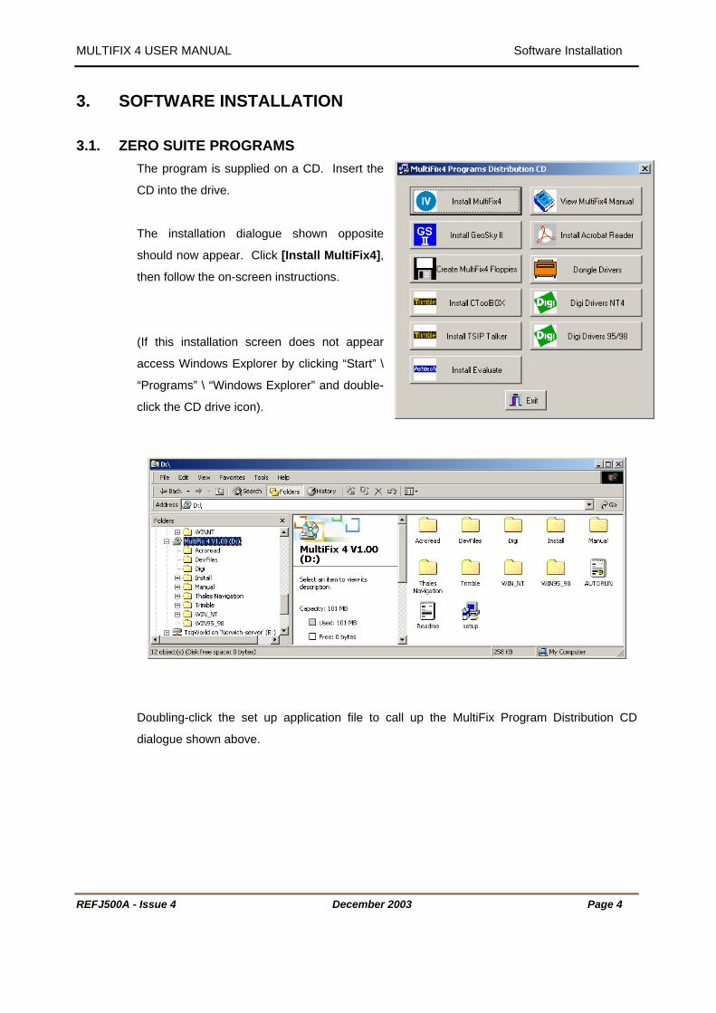
3.1. ZERO SUITE PROGRAMS The program is supplied on a CD. Insert the
CD into the drive.
The installation dialogue shown opposite
should now appear. Click [Install MultiFix4],
then follow the on-screen instructions.
(If this installation screen does not appear
access Windows Explorer by clicking “Start” \
“Programs” \ “Windows Explorer” and double-
click the CD drive icon).
Doubling-click the set up application file to call up the MultiFix Program Distribution CD
dialogue shown above.
REFJ500A - Issue 4 December 2003 Page 4
MULTIFIX 4 USER MANUAL Software Installation
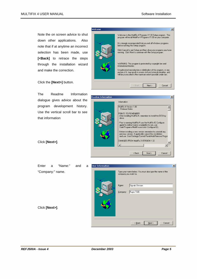
Note the on screen advice to shut
down other applications. Also
note that if at anytime an incorrect
selection has been made, use
[<Back] to retrace the steps
through the installation wizard
and make the correction.
Click the [Next>] button.
The Readme Information
dialogue gives advice about the
program development history.
Use the vertical scroll bar to see
that information
Click [Next>].
Enter a “Name:” and a
“Company:” name.
Click [Next>].
REFJ500A - Issue 4 December 2003 Page 5
MULTIFIX 4 USER MANUAL Software Installation
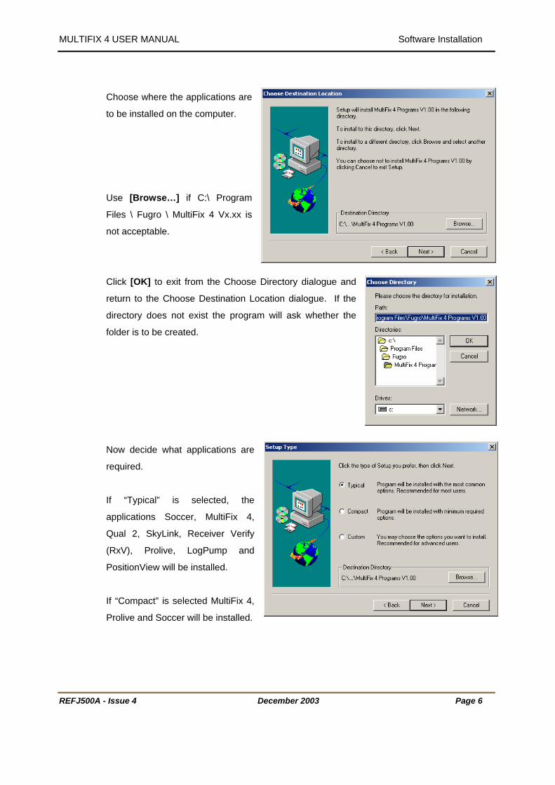
Choose where the applications are
to be installed on the computer.
Use [Browse…] if C:\ Program
Files \ Fugro \ MultiFix 4 Vx.xx is
not acceptable.
Click [OK] to exit from the Choose Directory dialogue and
return to the Choose Destination Location dialogue. If the
directory does not exist the program will ask whether the
folder is to be created.
Now decide what applications are
required.
If “Typical” is selected, the
applications Soccer, MultiFix 4,
Qual 2, SkyLink, Receiver Verify
(RxV), Prolive, LogPump and
PositionView will be installed.
If “Compact” is selected MultiFix 4,
Prolive and Soccer will be installed.
REFJ500A - Issue 4 December 2003 Page 6
MULTIFIX 4 USER MANUAL Software Installation
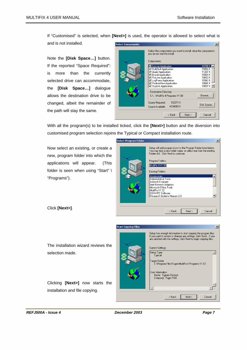
If “Customised” is selected, when [Next>] is used, the operator is allowed to select what is
and is not installed.
Note the [Disk Space…] button.
If the reported “Space Required”:
is more than the currently
selected drive can accommodate,
the [Disk Space…] dialogue
allows the destination drive to be
changed, albeit the remainder of
the path will stay the same.
With all the program(s) to be installed ticked, click the [Next>] button and the diversion into
customised program selection rejoins the Typical or Compact installation route.
Now select an existing, or create a
new, program folder into which the
applications will appear. (This
folder is seen when using “Start” \
“Programs”).
Click [Next>].
The installation wizard reviews the
selection made.
Clicking [Next>] now starts the
installation and file copying.
REFJ500A - Issue 4 December 2003 Page 7

MULTIFIX 4 USER MANUAL Software Installation
After copying the files the installation wizard states it is Creating Icons and Updating Registry
Information.
A “MultiFix 4 Vx.xx” window is also
opened and then minimised. It
contains shortcuts to all the
programs selected for installation.
Clicking [Finish] completes the
MultiFix Vx.xx programs installation
process.
REFJ500A - Issue 4 December 2003 Page 8

MULTIFIX 4 USER MANUAL Software Installation
3.2. DONGLE DRIVERS Because MultiFix 4 is dongle protected the
dongle driver needs to be installed before the
software can be used.
In the distribution dialogue click the [Dongle
Drivers] button.
REFJ500A - Issue 4 December 2003 Page 9

MULTIFIX 4 USER MANUAL Software Installation
Note: - Using “Start” \ “Settings” \ “Control Panel” \ “Add/Remove Programs” check that there
are not two DK DESKey dongle drivers loaded. For example the PC may have been used to
run GNS2 with a DK12 dongle and the driver for that dongle is still installed. There are known
conflicts when both are installed and the program may run for a while then report that there is
no dongle present. Remove the DK12 dongle driver.
After copying the files there is again the invitation to restart the computer. This is necessary if
MultiFix 4 is to be run straight away.
REFJ500A - Issue 4 December 2003 Page 10

MULTIFIX 4 USER MANUAL Software Installation
3.3. DIGIBOARD DRIVERS To install Digiboard drivers click the relevant
button for the Windows operating system
under which the program is to run. The Digi
drivers for Windows 2000 are part of the
Windows 2000 operating system.
The example that follows is for Windows NT with a PC/8e Digiboard.
1. Click the arrow button in section 1 of
“Device Driver Installation”.
2. In the Networks dialogue, click [Add…]
3. In the Select Network Adapter dialogue,
click [Have Disk…].
4. In the Insert Disk dialogue type in the CD-
ROM drive letter followed by \Win_nt\i386,
e.g.D:\Win_nt\i386.
5. In the Select OEM Option dialogue
highlight the Digiboard installed in the
computer, for example “Digi PC/8e(ISA)
Adapter”, click [OK].
6. In the Digiboard Adapter dialogue, check
the “IO base port” and the “Memory base
address”. In the case of the PC/8e board,
the “IO base port” number is set by the DIP
switch settings, see diagram below. The “Memory base address” for a PC/8e is typically
D0000. Click [OK] to exit.
REFJ500A - Issue 4 December 2003 Page 11

MULTIFIX 4 USER MANUAL Software Installation
View through aperture
Figure 1 PC/8e Switch S
7. [Close] the Network d
The Digiboard
higher than the
REFJ500A - Issue 4
in the board end plate
1 2
3 4
I/O Port Addess320h-323h
1 2
3 4
I/O Port Address300h-303h
1 2
3 4
I/O Port Address220h-223h
1 2
3 4
I/O Port Address200h-203h
1 2
3 4
I/O Port Addess120h-123h
1 2
3 4
I/O Port Address110h-113h
1 2
3 4
I/O Port Address100h-103h
ettings for IO Base Address
ialogue and as requested restart the computer.
s must be mapped to the COM ports. The first Digiport should be numbered 1
in built ports in the computer.
December 2003 Page 12
MULTIFIX 4 USER MANUAL Software Installation
REFJ500A - Issue 4 December 2003 Page 13
3.4. PRE-CONFIGURATION Assuming data is being input and or output via COM ports, before MultiFix 4 is run it is
necessary to let the program know what COM ports are available.
Likewise, assuming position data outputs will be required from MultiFix 4 the program needs
to know the how to build those output messages. To do that, *.zpo output library files must be
selected.
To accomplish both the above tasks, access the MultiFix Vx.xx IO Configuration Control
Panel by selecting “Start” \ “Programs” \ “MultiFix 4 Vx.xx” \ “Configure IO”
As seen below the MultiFix IO Configuration dialogue has two tabs.
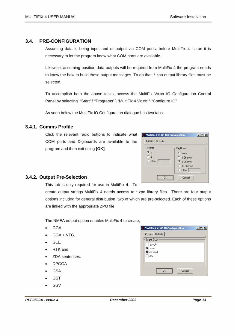
3.4.1. Comms Profile Click the relevant radio buttons to indicate what
COM ports and Digiboards are available to the
program and then exit using [OK].
3.4.2. Output Pre-Selection This tab is only required for use in MultiFix 4. To
create output strings MultiFix 4 needs access to *.zpo library files. There are four output
options included for general distribution, two of which are pre-selected. Each of these options
are linked with the appropriate ZPO file
The NMEA output option enables MultiFix 4 to create,
• GGA,
• GGA + VTG,
• GLL,
• RTK and
• ZDA sentences.
• DPGGA
• GSA
• GST
• GSV

MULTIFIX 4 USER MANUAL Software Installation
REFJ500A - Issue 4 December 2003 Page 14
The STANDARD option enables MultiFix 4 to create,
• Trimble
• DNav
• ZeroLink
• Fugro UKOOA
• Geco UKOOA
• Geco UKOOA Version 2
• Fugro XP Expanded and
• Fugro XP Concise messages
The UTM option allows MultiFix 4 to create the Syledis and GEM 80 DP outputs.
The DGPS_IS option is a development tool and not required for standard work.
Two options, NMEA and STANDARD options are pre-selected by default. To add the UTM or
DGPS_IS outputs check the appropriate boxes.
The set up of various outputs is covered in Section 4.3.3.5 on page 69. The format of the
messages can be found in APPENDIX A - DATA OUTPUT STRINGS on page 316.
NOTE that the “Automatically adjust clock for daylight saving changes” option in the
“Time Zone” tab under “Start” \ “Settings” \ “Control Panel” \ “Date/Time” should NOT
be checked.

MULTIFIX 4 USER MANUAL MultiFix 4
REFJ500A - Issue 4 December 2003 Page 15
4. MULTIFIX 4 4.1. INTRODUCTION
MultiFix 4 is Fugro’s fourth generation differential GPS real time position computation and QC
program. It is an integral part of the SkyFix Premier service but can also be used with the
standard SkyFix service. MultiFix 4 was released as a MultiFix 3 replacement but includes a
new positioning mode called SkyFix-XP.
MultiFix 4 takes in Almanac, Ephemeris, Raw Code and Carrier measurements from either a
single or a dual frequency GPS receiver (or from logged files for replay purposes).
It also inputs RTCM SC104 Version 2 differential correction messages from one or more
RTCM Correction delivery systems, and Fugro Proprietary RTCM Type 55 Ionospheric range
corrections. These are generated at selected SkyFix Premier reference stations and
broadcast via the Fugro global network of high and low power L Band beams.
• There is no limit on the number of RTCM correction delivery systems.
• There is no limit on the number of RTCM differential reference stations.
• There is no limit on the number of computations.
• Each computation can employ corrections from any combination of reference
stations available.
• The statistical evaluations are based upon the UKOOA recommendations.
• There is no limit on the number of outputs.
• There is no limit on the number of view windows.
• The view windows can be customised.
MultiFix 4 has been designed in a modular fashion such that data is passed between modules
as if over a computer network. The core module MultiFix 4 performs the computation of the
GPS antenna position. Additional modules are available with more to be made available in
the future. While a single computer can be used, the various modules will equally be able to
be run on different computers provided there is a network interconnection.
MultiFix 4 uses the EGM96 geoid/spheroid separation model.
The RTCM corrections that are generated at reference stations are contaminated by a variety
of error components, one of which is Ionospheric delay. The Ionospheric delay is currently
more variable because of greater sun spot activity. MultiFix 4’s standard computation uses
the Klobachar Ionospheric delay model. This model is updated periodically but is not
responsive to the current short-term variability. MultiFix 4 has an additional calculation option
when working with dual frequency receivers and when in receipt of Type 15 or 55 RTCM

MULTIFIX 4 USER MANUAL MultiFix 4
messages. With dual frequency receivers, estimates can be made of the Ionospheric delay
by examining the differences between the measurements from the two frequencies. If the
same procedure for estimation of Ionospheric delay is performed at the reference stations and
on the mobile, both the RTCM corrections and the pseudo-ranges can have the Ionospheric
delay removed, effectively providing an Iono-Free DGPS position solution.
SkyFix-XP approaches the differential technique from a totally different perspective. The
global network of reference stations is used to track all satellites continuously throughout their
orbit. These global observation sets are then combined into a single correction process. This
process identifies, isolates and measures each individual source of error and provides a
complete set of orbit corrections for each GPS satellite. As such this measurement set can
be used at any location, regardless of distance to a reference station, making the system truly
global. This technique is called SDGPS, Satellite Differential GPS, as the differential
corrections are for the GPS satellite and not a specific reference station.
The remaining tropospheric and ionospheric error sources are estimated or eliminated at the
user end. The Tropospheric error is removed utilising a Tropospheric modelling technique as
part of the position calculation. Whilst the ionospheric delay is eliminated by using a dual
frequency GPS receiver at the users location. Multipath and receiver noise at the users
location are limited by using the carrier phase observations.
The SkyFix-XP SDGPS corrections are generated from two independent systems, each being
identified by a unique source code ‘0’ and ‘1’. In case of failure on one system the correction
source will automatically switch to the remaining system at the Network Control Centre.
Fugro’s MultiFix 4 QC software can automatically identify a change in correction source and
will notify the user without affecting the position calculation.
To provide an absolute confirmation of accuracy Fugro has installed regional monitor systems
at a number of SkyFix stations at locations that are key to offshore operation. These provide
real-time system performance information on the SkyFix Club website.
The text in this manual conforms to certain conventions
1. All command buttons are shown bold and bracketed with square brackets e.g. [OK],
2. When a keyboard key is represented, it is shown bold and bracketed by greater than and
lesser than symbols e.g. <spacebar>.
3. Direct quotations from dialogues or edit control slots are shown in normal text in
quotations, e.g. “IO Channel:”
REFJ500A - Issue 4 December 2003 Page 16

MULTIFIX 4 USER MANUAL MultiFix 4
4.2. CONFIGURATION 4.2.1. SkyFix Single Frequency
The following diagrams outlines the hardware requirements and interconnections for a standard single-
frequency SkyFix set up using Fugro’s MK3 or MK5 decoders and an Ashtech DG16 GPS receiver.
Figure 2 Example Interconnection with an Ashtech DG16 Receiver
REFJ500A - Issue 4 December 2003 Page 17

MULTIFIX 4 USER MANUAL MultiFix 4
4.2.2. SkyFix-XP / Premier Dual - Frequency
The following diagrams outlines the hardware requirements and interconnections for a SkyFix-XP or
Premier dual-frequency set up using an Ashtech ZX Sensor or Trimble MS750 receiver.
Figure 3. Example Interconnection with Ashtech ZX Sensor or Trimble MS750 Receiver
Although not shown above, other configurations are supported where the RTCM decoder has a GPS
receiver board fitted. MultiFix 4 is then able to take the GPS measurement and other data as well as the
RTCM correction from the Decoder.
REFJ500A - Issue 4 December 2003 Page 18

MULTIFIX 4 USER MANUAL MultiFix 4
4.2.3. HARDWARE REQUIREMENT
MultiFix 4 requires the following:
A PC running Windows 98, Windows NT, Windows 2000 or Windows XP. The minimum recommended
PC is a Pentium III (or equivalent) processor with 128 MB RAM. A graphics resolution of at least 1024 by
768 pixels is advised in order to achieve maximum clarity of all the graphics displays. If two copies of
MultiFix 4 are to be run on the same machine, or if more than 15 reference stations are used, then it is
recommended to have a minimum of 256MB RAM.
For the installation of the software the PC requires a CD-ROM drive. It is possible to create installation
floppy discs from the installation menu on the CD but 8 floppies are needed.
MultiFix 4 needs a single frequency GPS receiver to run in standard mode and a dual frequency GPS
receiver to run in dual frequency SkyFix Premier or SkyFix-XP mode.
MultiFix 4 supports the following GPS receivers:
Manufacturer Model Type Baud Rate
(Minimum)
Baud Rate
(Recommended)
Ashtech (Thales Navigation) Z Family Dual 38400 57600
Ashtech (Thales Navigation) DG16 Single 9600 9600
Ashtech (Thales Navigation) G12 Single 9600 9600
Ashtech (Thales Navigation) GG24 Single 9600 9600
Trimble BD112 Single 9600 9600
Trimble DSM Single 9600 9600
Trimble DSM212 Single 9600 9600
Trimble SK8 Single 9600 9600
Trimble 4000DS Single 9600 9600
Trimble BD750 Dual 38400 57600
Trimble MS750 Dual 38400 57600
Trimble 5700 Dual 38400 57600
Trimble 4000 SSE Dual 38400 57600
Trimble 4000 SSi Dual 38400 57600
NovAtel OEM4 Dual 57600 57600
NovAtel Millennium Dual 38400 57600
REFJ500A - Issue 4 December 2003 Page 19

MULTIFIX 4 USER MANUAL MultiFix 4
Assuming data is not being input or output over network sockets, the PC needs a minimum of 2 COM
ports. One COM port is used for two-way communications to the GPS receiver and the second COM
port for the input of RTCM corrections. As the second port is for input only it can also be used to output
position messages by using a special breakout cable.
If there is more than one RTCM delivery system, or data is to be output on several ports, then additional
COM ports will normally be required. These can be any proprietary asynchronous serial board (or
PCMCIA card). The Windows drivers for these allow the board’s (or card’s) ports to be mapped as
additional COM ports.
REFJ500A - Issue 4 December 2003 Page 20

MULTIFIX 4 USER MANUAL MultiFix 4
4.2.4. GPS RECEIVER CONFIGURATIONS
4.2.4.1. Ashtech (Thales Navigation) Receivers
Ashtech receivers can be controlled either from within MultiFix or externally using the Evaluate software
from Thales Navigation.
Evaluate must be used to establish and configure baud rates, but once communications have been
established between the PC and MultiFix then MultiFix can complete the configuration process.
4.2.4.1.1.Configuration from within MultiFix
Assuming communications have been established between MultiFix and the
GPS receiver then the receiver can be configured automatically by MultiFix.
The Command “Action” \ “Configure Ashtech” will launch the receiver
configuration dialogue.
Select Set default configuration to complete the receiver configuration.
Note that if using a Z Family receiver then the Baud Rate must be set to a
minimum of 38400 due to the large amount of data output from the receiver.
See section 4.3.5.6 for more details.
4.2.4.1.2.Ashtech Evaluate Configuration
Direct configuration of Ashtech receivers is usually via the Ashtech Evaluate program; alternatively they
can be configured using a terminal program. The following relates to Ashtech Evaluate which is included
on the MultiFix 4 installation CD.
Sample configuration files are also available on this CD.
After installing the Evaluate software start the program
by clicking the Ashtech Evaluate icon in the start menu.
The user will be asked to choose a start up option.
Select “Connect to GPS Receiver” and click [OK].
REFJ500A - Issue 4 December 2003 Page 21

MULTIFIX 4 USER MANUAL MultiFix 4
In the Connection Parameters dialogue select the PC Port, tick the “Initialize from file:” box, remove the
tick from all other boxes and select and the preferred initialisation file.
Pre-configured initialisation files can be found on the MultiFix 4
installation CD. These files must first be copied to the Evaluate \
Receiver folder.
Alternatively a file can be created from the text below. Re-name the
new text file with a *.gps extension and place it in the Evaluate \
Receiver folder.
The benefit of using an initialisation file is that all configuration
commands are sent to the receiver in a preferred sequence and can be followed by a command that
saves all these settings in the battery backed-up memory of the receiver.
On clicking [Connect], the software will try to
establish connection with the receiver.
If the PC COM port settings do not match the
port setting of the internal port on the GPS
receiver, Evaluate will report that the GPS
receiver is not responding.
By selecting the [AutoSelect], Evaluate will cycle through all possible COM port parameter settings and
will report if it finds the current receiver. Evaluate will then connect with the newly found settings.
If no matching port
is powered on.
REFJ500A - Issue 4
settings are found, investigate all cable connections and make sure that the receiver
December 2003 Page 22

MULTIFIX 4 USER MANUAL MultiFix 4
4.2.4.1.3.Ashtech Z-Family
The MF4_ZX.gps file contains
;
; Initialisation file for ZX-Sensor with MultiFix
;
; Set Measurement recording interval
$PASHS,RCI,1
; Set Raw Measurement elevation mask to 0 degrees
$PASHS,ELM,0
; Set the minimum number of SV measurements to 1
$PASHS,MSV,1
; Enable GGA position output
$PASHS,NME,GGA,A,ON
; Set GGA output to 10 second intervals
$PASHS,NME,PER,10
; Set Multipath Correlator
$PASHS,MLP,COD
; Enable UTS
$PASHS,UTS,Y
; Set the port A baud rate to 38400
$PASHS,SPD,7
; Enable the GPS Almanac GPS Ephemeris and GPS Measurement Messages
$PASHS,OUT,A,MBN,SNV,SAL,BIN
; Enable the GPS Almanac
$PASHR,ALM,A
; Save all current settings into the battery backed up memory
$PASHS,SAV,Y
REFJ500A - Issue 4 December 2003 Page 23
MULTIFIX 4 USER MANUAL MultiFix 4
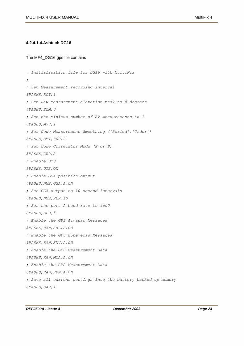
4.2.4.1.4.Ashtech DG16
The MF4_DG16.gps file contains
; Initialisation file for DG16 with MultiFix
;
; Set Measurement recording interval
$PASHS,RCI,1
; Set Raw Measurement elevation mask to 0 degrees
$PASHS,ELM,0
; Set the minimum number of SV measurements to 1
$PASHS,MSV,1
; Set Code Measurement Smoothing ('Period','Order')
$PASHS,SMI,300,2
; Set Code Correlator Mode (E or S)
$PASHS,CRR,S
; Enable UTS
$PASHS,UTS,ON
; Enable GGA position output
$PASHS,NME,GGA,A,ON
; Set GGA output to 10 second intervals
$PASHS,NME,PER,10
; Set the port A baud rate to 9600
$PASHS,SPD,5
; Enable the GPS Almanac Messages
$PASHS,RAW,SAL,A,ON
; Enable the GPS Ephemeris Messages
$PASHS,RAW,SNV,A,ON
; Enable the GPS Measurement Data
$PASHS,RAW,MCA,A,ON
; Enable the GPS Measurement Data
$PASHS,RAW,PBN,A,ON
; Save all current settings into the battery backed up memory
$PASHS,SAV,Y
REFJ500A - Issue 4 December 2003 Page 24

MULTIFIX 4 USER MANUAL MultiFix 4
4.2.4.1.5.Ashtech G12
The MF4_G12.gps configuration file contains the following.
; Initialisation file for G12 with MultiFix
;
; Set the SNR Calculation to dB/Hz independent of the hardware
$PASHS,SNR,DBH
; Set Measurement recording interval
$PASHS,RCI,1
; Set Raw Measurement elevation mask to 0 degrees
$PASHS,ELM,0
; Set the minimum number of SV measurements to 1
$PASHS,MSV,1
; Enable GGA position output
$PASHS,NME,GGA,A,ON
; Set GGA output to 10 second intervals
$PASHS,NME,PER,10
; Set the port A baud rate to 9600
$PASHS,SPD,5
; Enable the GPS Almanac Messages
$PASHS,RAW,SAL,A,ON
; Enable the GPS Ephemeris Messages
$PASHS,RAW,SNV,A,ON
; Enable the GPS Measurement Data
$PASHS,RAW,MCA,A,ON
; Save all current settings into the battery backed up memory
$PASHS,SAV,Y
REFJ500A - Issue 4 December 2003 Page 25

MULTIFIX 4 USER MANUAL MultiFix 4
4.2.4.1.6.Ashtech GG24
The MF4_GG24.gps file contains
; Initialisation file for GG24 with MultiFix
;
; Set System to GPS only mode
$PASHS,SYS,GPS
; Set Measurement recording interval
$PASHS,RCI,1
; Set Raw Measurement elevation mask to 0 degrees
$PASHS,ELM,0
; Set the minimum number of SV measurements to 1
$PASHS,MSV,1
; Enable GGA position output
$PASHS,NME,GGA,A,ON
; Set GGA output to 10 second intervals
$PASHS,NME,PER,10
; Set the port A baud rate to 9600
$PASHS,SPD,5
; Enable the GPS Almanac Messages
$PASHS,RAW,SAL,A,ON
; Enable the GPS Ephemeris Messages
$PASHS,RAW,SNV,A,ON
; Enable the GPS Measurement Data
$PASHS,RAW,MCA,A,ON
; Save all current settings into the battery backed up memory
$PASHS,SAV,Y
REFJ500A - Issue 4 December 2003 Page 26
MULTIFIX 4 USER MANUAL MultiFix 4
4.2.4.2. Trimble Receiver Configuration
4.2.4.2.1.Trimble BD112
Both the BD112 and the DSM are Trimble single frequency receiver boards. They can be mounted in a
90938. If the 90938 decoder has a BD112 board fitted it will have the suffix F112. If a DSM board is
fitted it will have the suffix /M.
The receiver boards do not retain configuration settings when not housed in a 90938, therefore when
power is recycled they revert to their default settings. One of those defaults is the COM port parameter
values which are 9600 8-ODD-1.
Within MultiFix use the Edit GPS Receiver dialogue (accessed using “Config” \ “GPS Rx…”) to select
BD112 (Trimble) from the drop down list of GPS receivers. Use “Action” \ “Configure TSIP” \ “Default” to
configure the receiver to output the required message types.
Note- The “Configure TSIP” menu item only becomes available if a TSIP protocol receiver is selected.
If it is clear that MultiFix 4 is not communicating with the receiver it may be due to baud rate or other
incompatibilities, (see Section 4.3.5.5 on page 86). In that case use the Trimble TSIP Talker application
that can be found on the MultiFix installation CD.
TSIP Talker contains an option called TSIP Break. If on start-up TSIP Talker fails to establish
communications with the receiver TSIP Break can be used. That will reset the Trimble serial port to 9600
8-ODD-1. Once communication has been established with those settings TSIP Talker can make further
changes to the communication parameter settings.
Once the communication has been established return to “Action” \ “Configure TSIP” \ “Default” in MultiFix
4 to complete the receiver configuration.
4.2.4.2.2.Trimble DSM
As 4.2.4.2.1 but selecting DSM (Trimble) in place of BD112 (Trimble) from the drop down list of receivers.
4.2.4.2.3.Trimble DSM212
The DSM212 is a DSM single frequency receiver board housed in its own box. The front panel of the box
has no control buttons. Connect the MultiFix 4 computer to either of the serial ports on the back of the
DSM212 unit.
REFJ500A - Issue 4 December 2003 Page 27

MULTIFIX 4 USER MANUAL MultiFix 4
REFJ500A - Issue 4 December 2003 Page 28
SV:07 PDOP3.2
RTK(FIX)
Config GPS
Press ∨ to Enter
Cnf:System Masks
Elev 10 Pdop 07
Config Ports
Press ∨ to Enter
CFG: Exiti
Pre to
4.2.4.2.4.Trimble SK8
The Trimble SK8 is a navigation grade GPS receiver. It should not normally be used for survey
operations.
The SK8 uses the same TSIP protocol as the DSM and BD112. It is also configured in the same way as
per section 4.2.4.2.
4.2.4.2.5.Trimble MS750
The configuration of the MS 750 dual frequency receiver must be done in two stages. The first stage is
via the front panel of the unit itself, and the second stage is via the “Yellow Box” display accessed from
the “Receiver” option in the “View” / “GPS” pull-down menus.
IMPORTANT NOTE – It is essential that the baud rate is set to 38400 as if too low a baud rate (9600) is
used then the serial port may be over loaded when there is a high number of SVs visible (greater than
10).
4.2.4.2.5.1.Front Panel Configuration
When the MS 750 is powered up, the front panel displays the Home screen
(shown opposite). Use the green “>” button to toggle to the “Config GPS”
display.
The screen shown opposite will now appear. Press the “∨” button to access
the “System Masks “ display.
Press the “>” button to enable the cursor. Set the elevation mask to 0° and
the PDOP mask to 99. Use the “>” button to move the cursor and the “∧”
and “∨” buttons to change the values. Press the “↵” button to accept the entry.
Toggle to the “Exit Config” display by pressing the “∨” button. Press “↵” to
exit this display and return to the “Config GPS” screen. Press “>” to
toggle to the “Config Ports” screen.
This will bring up the screen shown here. Press the “∨" button to toggle
to the Port A configuration display.
The screen shown opposite will now appear. Use the “>” button to enable the
cursor. Set the Baud rates to 38400, 8-None–1 using the “>” button to move
the cursor and the “∧” and “∨” buttons to change the values. Then press “↵”.
CFG: Port A NONE
38400 8-NONE-1
CFG: NMEA GGA
Port A OFF
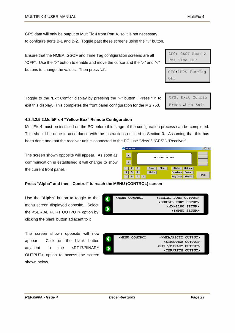
MULTIFIX 4 USER MANUAL MultiFix 4
REFJ500A - Issue 4 December 2003 Page 29
/MENU CONTROL <SERIAL PORT OUTPUT> <SERIAL PORT SETUP>
<JX-1100 SETUP><INPUT SETUP>
/MENU CONTROL <NMEA/ASCII OUTPUT><STREAMED OUTPUT>
<RT17/BINARY OUTPUT><CMR/RTCM OUTPUT>
CFG: Exit Config
Press ↵ to Exit
GPS data will only be output to MultiFix 4 from Port A, so it is not necessary
to configure ports B-1 and B-2. Toggle past these screens using the “∨” button.
Ensure that the NMEA, GSOF and Time Tag configuration screens are all
“OFF”. Use the “>” button to enable and move the cursor and the “∧” and “∨”
buttons to change the values. Then press “↵”.
Toggle to the “Exit Config” display by pressing the “∨” button. Press “↵” to
exit this display. This completes the front panel configuration for the MS 750.
4.2.4.2.5.2.MultiFix 4 “Yellow Box” Remote Configuration
MultiFix 4 must be installed on the PC before this stage of the configuration process can be completed.
This should be done in accordance with the instructions outlined in Section 3. Assuming that this has
been done and that the receiver unit is connected to the PC, use “View” \ “GPS” \ “Receiver”.
The screen shown opposite will appear. As soon as
communication is established it will change to show
the current front panel.
Press “Alpha” and then “Control” to reach the MENU (CONTROL) screen
Use the “Alpha” button to toggle to the
menu screen displayed opposite. Select
the <SERIAL PORT OUTPUT> option by
clicking the blank button adjacent to it
The screen shown opposite will now
appear. Click on the blank button
adjacent to the <RT17/BINARY
OUTPUT> option to access the screen
shown below.
CFG: GSOF Port A
Pos Time OFF
CFG:1PPS TimeTag
Off

MULTIFIX 4 USER MANUAL MultiFix 4
Using the “Enter” button to toggle to the
desired parameter. Ensure that the
correct output port is enabled and then set
MEASUREMENTS and POSITIONS to
1HZ using the “Alpha” button. EPHEMERIS should be set to “ON” (optional) and all other parameters
should be set to “OFF”.
RT17/BINARY OUTPUT (CONTROL) PORT [ A ] CONCISE [OFF]
MEASUREMENTS [1HZ] R-T FLAGS [OFF] POSITIONS [1HZ] EPHEMERIS [OFF]
Click on “Enter” until the MENU (CONTROL) screen is displayed.
4.2.4.2.6.Trimble BD750
The Trimble BD750 is the board version of the MS750 and can be found mounted inside the 90938
Genesis units. I/O configuration of the ports is via the front panel of the 90938. Configuration of the
BD750 is via yellow box, as per Section 4.2.4.2.5.2.
4.2.4.2.7.Trimble 5700
The configuration of the 5700 dual frequency receiver must be done in two stages. The first stage is
completed using the Trimble Configuration Toolbox software, and the second stage is via the “Yellow
Box” display accessed from the “Receiver” option in the “View” / “GPS” pull-down menus.
IMPORTANT NOTE – It is essential that the baud rate is set to 38400 as if too low a baud rate (9600) is
used then the serial port may be over loaded when there is a high number of SVs visible (>10).
4.2.4.2.7.1.Trimble’s Configuration Toolbox
Trimble’s ‘Configuration Toolbox’ software is used initially to establish communications with the 5700.
The software is available from Trimble or from a MultiFix installation disk. Connect the receiver to the PC
as directed above and start the ‘Configuration Toolbox’ software.
First direct the software to the Com port that the
receiver is connected to, “Communications” \ “Port”
REFJ500A - Issue 4 December 2003 Page 30
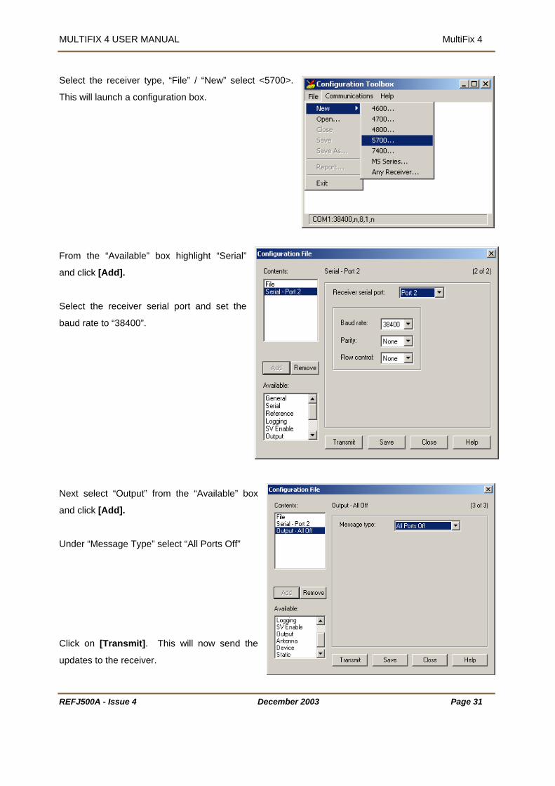
MULTIFIX 4 USER MANUAL MultiFix 4
Select the receiver type, “File” / “New” select <5700>.
This will launch a configuration box.
From the “Available” box highlight “Serial”
and click [Add].
Select the receiver serial port and set the
baud rate to “38400”.
Next select “Output” from the “Available” box
and click [Add].
Under “Message Type” select “All Ports Off”
Click on [Transmit]. This will now send the
updates to the receiver.
REFJ500A - Issue 4 December 2003 Page 31

MULTIFIX 4 USER MANUAL MultiFix 4
If the transfer is successful the following dialogue
box will appear. Click [Ok].
.
The “Configuration File” dialogue can be closed without saving. Exit the Configuration Toolbox software,
the remaining set-up of the 5700 will be completed in MultiFix.
4.2.4.2.7.2.MultiFix 4 “Yellow Box” Remote Configuration
This part of the configuration is identical to the Trimble MS750, see section 4.2.4.2.5.2 to complete 5700
configuration.
REFJ500A - Issue 4 December 2003 Page 32

MULTIFIX 4 USER MANUAL MultiFix 4
REFJ500A - Issue 4
PORT 1 BAUD RATE [ 9600 ] <- CHANGE
4.2.4.2.8.Trimble 4000DS
Set the COM Port Protocol Parameter Values
CONTROL / MORE…/
BAUD RATE/FORMAT /
SERIAL PORT n SETTINGS / CHANGE
Enable MultiFix 4 Control of Trimble Rece
CONTROL / MORE… /
REMOTE PROTOCOL
Select the Port for the MultiFix 4/Trimble
CONTROL / MORE... /
CYCLE PRINTOUTS /
Ensure there are no other
Receiver Cycle Outputs are enab
Select the Format for the MultiFix 4/Trimb
CONTROL / MORE... /
CYCLE PRINTOUTS /
(Use Middle Next)
Select the Port for the Receiver’s Input of
CONTROL/
RTCM-104 INPUT
Check there are No Other Outputs Enab
Port
CONTROL / MORE… /
NMEA-183 OUTPUT
FORMAT [ 8-NONE-1 ] <- CHANGE FLOW CONTROL [ NONE ] <- CHANGE
REMOTE INTERFACE PROTOCOL
iver
R
[ DATA COLLECTOR COMPATIBLE ] <-- CHANGE (STX,DATA,CHECKSUM,ETX)
OUTPUT EVERY RECEIVER CYCLE
eceiver Communication
RT SURVEY DATA <-- NEXT PORT SELECTION <-- NEXT ENABLE [ PORT 2 ] <-- CHANGE
OUTPUT EVERY RECEIVER CYCLE RT SURVEY DATA <-- NEXT CONCISE FORMAT <-- NEXT ENABLE [ ON ] <-- CHANGE
DIFFERENTIAL STATION <-- MORERTCM-104 INPUTS [ ON/AUTO ] <-- CHANGE PORT SELECT [ PORT 1 ] <-- CHANGE FORMAT [ VERSION 2 ] <-- CHANGE
led (Use Top Next)
le Receiver Communication
RTCM Corrections
led On the MultiFix 4/Trimble Receiver Communication
December 2003 Page 33
NMEA-183 ENABLE[ OFF ] <-- CHANGEOUTPUT CONTROL ALM[ OFF ] <-- CHANGE BWC[ OFF ] <-- CHANGE MORE
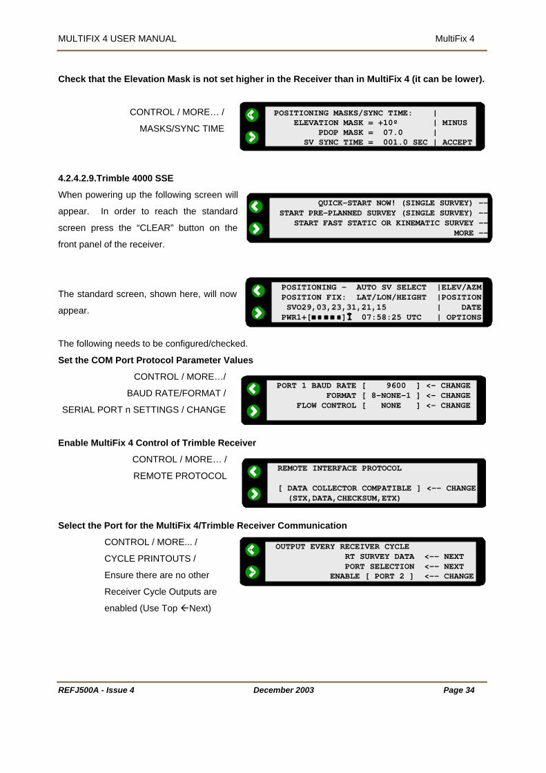
MULTIFIX 4 USER MANUAL MultiFix 4
REFJ500A - Issue 4
QUICK-START NOW! (SINGLE SURVEY) --START PRE-PLANNED SURVEY (SINGLE SURVEY) -- START FAST STATIC OR KINEMATIC SURVEY -- MORE --
PORT 1 BAUD RATE [ 9600 ] <- CHANGE
POSITIONING MASKS/SYNC TIME: | ELEVATION MASK = +10º | MINUS PDOP MASK = 07.0 | SV SYNC TIME = 001.0 SEC | ACCEPT
POSITIONING - AUTO SV SELECT |ELEV/AZMPOSITION FIX: LAT/LON/HEIGHT |POSITION SVO29,03,23,31,21,15 | DATEPWR1+[ ] 07:58:25 UTC | OPTIONS
Check that the Elevation Mask is not set higher in the Receiver than in MultiFix 4 (it can be lower).
CONTROL / MORE… /
MASKS/SYNC TIME
4.2.4.2.9.Trimble 4000 SSE
When powering up the following screen will
appear. In order to reach the standard
screen press the “CLEAR” button on the
front panel of the receiver.
The standard screen, shown here, will now
appear.
The following needs to be configured/checked.
Set the COM Port Protocol Parameter Values
CONTROL / MORE…/
BAUD RATE/FORMAT /
SERIAL PORT n SETTINGS / CHANGE
Enable MultiFix 4 Control of Trimble Rece
CONTROL / MORE… /
REMOTE PROTOCOL
Select the Port for the MultiFix 4/Trimble
CONTROL / MORE... /
CYCLE PRINTOUTS /
Ensure there are no other
Receiver Cycle Outputs are
enabled (Use Top Next)
FORMAT [ 8-NONE-1 ] <- CHANGE FLOW CONTROL [ NONE ] <- CHANGE
REMOTE INTERFACE PROTOCOL
iver
[ DATA COLLECTOR COMPATIBLE ] <-- CHANGE (STX,DATA,CHECKSUM,ETX)
OUTPUT EVERY RECEIVER CYCLE
Receiver Communication
December 2003 Page 34
RT SURVEY DATA <-- NEXT PORT SELECTION <-- NEXT ENABLE [ PORT 2 ] <-- CHANGE

MULTIFIX 4 USER MANUAL MultiFix 4
REFJ500A - Issue 4
OUTPUT EVERY RECEIVER CYCLE RT SURVEY DATA <-- NEXT CONCISE FORMAT <-- NEXT ENABLE [ ON ] <-- CHANGE
NMEA-183 ENABLE[ OFF ] <-- CHANGE
DIFFERENTIAL STATION <-- MORERTCM-104 INPUTS [ ON/AUTO ] <-- CHANGE PORT SELECT [ PORT 1 ] <-- CHANGE FORMAT [ VERSION 2 ] <-- CHANGE
Select the Format for the MultiFix 4/Trimble Receiver Communication
CONTROL / MORE... /
CYCLE PRINTOUTS /
(Use Middle Next)
Select the Port for the Receiver’s Input of RTCM Corrections
CONTROL/
RTCM-104 INPUT
Check that there are no other outputs enabled On the MultiFix 4/Trimble Receiver Communication
Port
CONTROL / MORE… /
NMEA-183 OUTPUT
Check that the Elevation Mask is not set
CONTROL / MORE… /
MASKS/SYNC TIME
Ensure the receiver is set to dual freque
CONTROL / MORE…/
L1 / L2 OPERATION
Only the L2 code can be disabled. Ensure
OUTPUT CONTROL ALM[ OFF ] <-- CHANGE BWC[ OFF ] <-- CHANGE MORE
higher in the Receiver than in MultiFix 4 (it can be lower)
POSITIONING MASKS/SYNC TIME: | ELEVATION MASK = +10º | MINUS PDOP MASK = 07.0 | SV SYNC TIME = 001.0 SEC | ACCEPT
ncy mode
L1/L2 TRACKING: P,C/A-CODE | L1 TRACKING
December 2003 Page 35
that both the L1 and L2 codes are enabled.
P,X-CODE | L2 TRACKING

MULTIFIX 4 USER MANUAL MultiFix 4
REFJ500A - Issue 4
QUICK-START NOW! (SINGLE SURVEY) --START PRE-PLANNED SURVEY (SINGLE SURVEY) -- START FAST STATIC OR KINEMATIC SURVEY -- MORE --
PORT 1 BAUD RATE [ 9600 ] <- CHANGE
POSITIONING - AUTO SV SELECT |ELEV/AZMPOSITION FIX: LAT/LON/HEIGHT |POSITION SVO29,03,23,31,21,15 | DATEPWR1+[ ] 07:58:25 UTC | OPTIONS
4.2.4.2.10.Trimble 4000 SSi
When powering up the following screen will
appear. In order to reach the standard
screen press the “CLEAR” button on the
front panel of the receiver.
The standard screen, shown here, will now
appear.
The following needs to be configured/checked.
Set the COM Port Protocol Parameter Values
CONTROL / MORE…/
BAUD RATE/FORMAT /
SERIAL PORT n SETTINGS / CHANGE
Enable MultiFix 4 Control of Trimble Rece
CONTROL / MORE… /
REMOTE PROTOCOL
Select the Port for the MultiFix 4/Trimble
CONTROL / MORE... /
CYCLE PRINTOUTS /
Ensure there are no other
Receiver Cycle Outputs are
enabled (Use Top Next)
Select the Format for the MultiFix 4/Trimb
CONTROL / MORE... /
CYCLE PRINTOUTS /
(Use Middle Next)
FORMAT [ 8-NONE-1 ] <- CHANGE FLOW CONTROL [ NONE ] <- CHANGE
REMOTE INTERFACE PROTOCOL
iver
[ DATA COLLECTOR COMPATIBLE ] <-- CHANGE (STX,DATA,CHECKSUM,ETX)
OUTPUT EVERY RECEIVER CYCLE
Receiver Communication
December 2003 Page 36
RT SURVEY DATA <-- NEXT PORT SELECTION <-- NEXT ENABLE [ PORT 2 ] <-- CHANGE
OUTPUT EVERY RECEIVER CYCLE RT SURVEY DATA <-- NEXT CONCISE FORMAT <-- NEXT ENABLE [ ON ] <-- CHANGE
le Receiver Communication

MULTIFIX 4 USER MANUAL MultiFix 4
Select the Port for the Receiver’s Input o
DIFFERENTIAL STATION <-- MORERTCM-104 INPUTS [ ON/AUTO ] <-- CHANGE PORT SELECT [ PORT 1 ] <-- CHANGE FORMAT [ VERSION 2 ] <-- CHANGE
NMEA-183 ENABLE[ OFF ] <-- CHANGE
f RTCM Corrections
CONTROL/
RTCM
heck there are no other outputs enabled On the MultiFix 4/Trimble Receiver Communication Port
heck that the Elevation Mask is not
a
nsure the receiver is set to dual freque
nly the L2 code can be disabled. Ensure
-104 INPUT
C
CONTROL / MORE… /
NMEA-183 OUTPUT
C
set higher in the Receiver th
CONTROL / MORE… /
MASKS/SYNC TIME
E
CONTROL / MORE…/
L1 / L2 OPERATION
O
REFJ500A - Issue 4
OUTPUT CONTROL ALM[ OFF ] <-- CHANGE BWC[ OFF ] <-- CHANGE MORE
n in MultiFix 4 (it can be lower)
POSITIONING MASKS/SYNC TIME: | ELEVATION MASK = +10º | MINUS PDOP MASK = 07.0 | SV SYNC TIME = 001.0 SEC | ACCEPT
L1/L2 TRACKING: P,C/A-CODE | L1 TRACKING P,E-CODE | L2 TRACKING
ncy mode
that both the L1 and L2 codes are enabled.
December 2003 Page 37

MULTIFIX 4 USER MANUAL MultiFix 4
4.2.4.3. NovAtel Receivers
4.2.4.3.1.NovAtel Millennium
For the NovAtel Millennium once communication has been established with the receiver using the
NovAtel GPSolution software, MultiFix 4 can then be used to finalise the configuration.
Communicating with the NovAtel Millennium OEM Card
Connect COM 1 on the NovAtel Millennium to COM 1 on the PC using a standard NovAtel
communication cable.
Run GPSolution
Go to “Card/Open..”
Create a “New...” configuration, for example
with the name ‘Millennium’, or “Edit…” it to
alter the settings.
REFJ500A - Issue 4 December 2003 Page 38

MULTIFIX 4 USER MANUAL MultiFix 4
Click “Settings…” on the edit configuration
dialogue, to enter the window for
configuring the Port parameters.
Select:
PC Port COM1
OEM Port COM1
Baud Rate 57600
Flow Control None.
Confirm with <OK>. This will
bring you back in the ‘Open
Configuration’ window. Select
<OK> GPSolution will now
attempt to establish
communication with the
NovAtel Millennium OEM card
In case this procedure fails to establish a connection at a 57600 baud rate and establishes
communication at a lower rate, the following steps allow the user to change the speed of the port.
REFJ500A - Issue 4 December 2003 Page 39

MULTIFIX 4 USER MANUAL MultiFix 4
Go to the “View/Command Console”. This will open the adjacent window:
Type Com1 57600,n,8,1,n,off,on in the Command Line followed by Enter. The display will read:
Upon changing the baud rate, you will lose communication with the card. In this case, close the
GPSolution application and restart using the configuration file created earlier.
REFJ500A - Issue 4 December 2003 Page 40
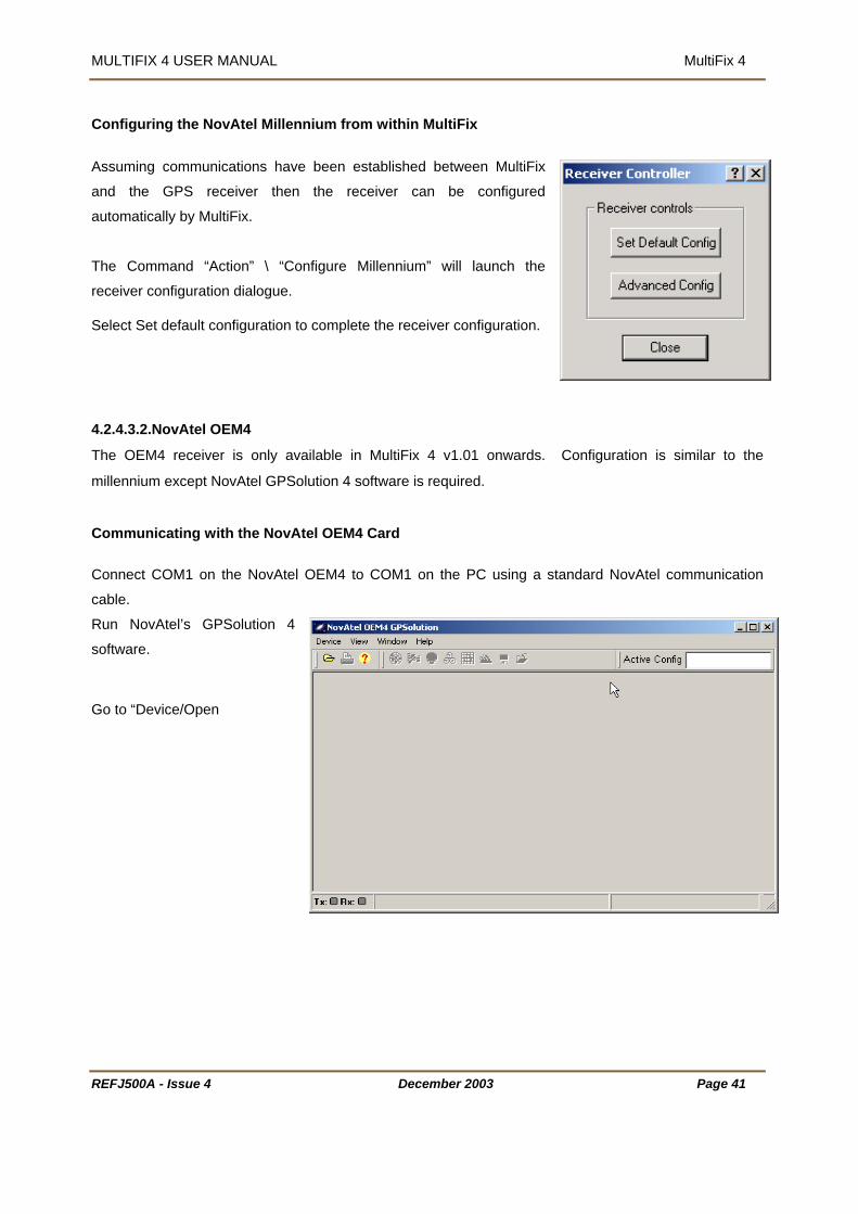
MULTIFIX 4 USER MANUAL MultiFix 4
Configuring the NovAtel Millennium from within MultiFix
Assuming communications have been established between MultiFix
and the GPS receiver then the receiver can be configured
automatically by MultiFix.
The Command “Action” \ “Configure Millennium” will launch the
receiver configuration dialogue.
Select Set default configuration to complete the receiver configuration.
4.2.4.3.2.NovAtel OEM4
The OEM4 receiver is only available in MultiFix 4 v1.01 onwards. Configuration is similar to the
millennium except NovAtel GPSolution 4 software is required.
Communicating with the NovAtel OEM4 Card
Connect COM1 on the NovAtel OEM4 to COM1 on the PC using a standard NovAtel communication
cable.
Run NovAtel’s GPSolution 4
software.
Go to “Device/Open
REFJ500A - Issue 4 December 2003 Page 41

MULTIFIX 4 USER MANUAL MultiFix 4
Create a “New...” configuration, for example with the name ‘OEM4’, or
“Edit…” it to alter the settings.
Type in a name and then click “Settings…” on the edit
configuration dialogue, to enter the window for configuring the
Port parameters.
Select: PC Port COM1
Baud Rate 57600
Hardware handshaking unchecked
Confirm with <OK> twice. This will bring you back in the ‘Open Configuration’ window. Select <Open> GPSolution will now attempt to establish communication with the NovAtel OEM4 card
In case this procedure fails to establish a connection at a 57600 baud rate and establishes
communication at a lower rate, the following steps allow the user to change the speed of the port.
REFJ500A - Issue 4 December 2003 Page 42

MULTIFIX 4 USER MANUAL MultiFix 4
Go to the “View/Console”. This will open
the adjacent window:
Type Com com1,57600,n,8,1,n,off in the Command Line followed by
Enter. The display will read:
Upon changing the baud rate, you will lose communication with the card. In this case, close the
GPSolution application and restart using the configuration file created earlier, but changing the baud rate
to 57600 in ‘Device Settings’.
Configuration from within MultiFix
Assuming communications have been established between MultiFix and the
GPS receiver then the receiver can be configured automatically by MultiFix
The Command “Action” \ “Configure OEM4” will launch the receiver
configuration dialogue.
Select Set default configuration to complete the receiver configuration.
REFJ500A - Issue 4 December 2003 Page 43

MULTIFIX 4 USER MANUAL MultiFix 4
4.2.5. MultiFix 4 Files Once MultiFix 4 has been installed and the program is run MultiFix 4 creates several files in
the folder specified by the operator for saving the configuration file.
The *.MF4 is the core MultiFix 4 configuration file and is stored in XML format.
*.MF4_PST is the Persistence file; it contains the number, type, position and contents of
windows in the application workspace when a configuration file is saved. It is written when
the program is exited.
*.MF4_SNR is the receiver signal to noise ratio weighting tables. This is written periodically
during a program run and when the configuration file is saved.
*.MF4_XAL file is the GPS almanac. This will be updated as the almanac changes and when
the configuration file is saved. The XAL file is stored as in an XML format and can be
exported to other applications.
*.MF4_ZRL is the Reference Location file that contains the positions of the reference stations
in use. It will be written when a new Type 3 position for a reference station is received and
when the configuration file is saved.
*.MF4_ZTP is the Trial Point configuration file that contains the current trial point position. It
is updated when the position as derived by the first calculation has moved more than 1 km
from the existing trial point position and when the configuration file is saved.
REFJ500A - Issue 4 December 2003 Page 44

MULTIFIX 4 USER MANUAL MultiFix 4
MF4_LSD is the Logging Schedule and will only be created when the program has logged
data. It contains information on what has been logged and the identifying numbers given to
the data. It is only written once logging has been started.
If log files are to be returned for analysis then ALL the above files should be returned also.
It is possible to modify an NMEA output string to accommodate clients’ software. The
definition of this modified string can be saved to a *.rdf file. The *.rdf file can then be
reloaded. By default the file is saved to the MultiFix 4 configuration file directory.
This folder will also contain text files logging any Type 16 messages that are received during
that day. See section 4.3.6.5.5 on page 123 for more details.
4.2.6. TO RUN MULTIFIX 4 MultiFix 4 can be opened a variety of ways.
Use Windows Explorer to display the contents of the folder containing the MultiFix 4 program
files and then double-clicking the “Multi4” application icon.
Use “Start” \ “Programs” \ “MultiFix 4 Vx.xx” and click “MultiFix 4”.
REFJ500A - Issue 4 December 2003 Page 45

MULTIFIX 4 USER MANUAL MultiFix 4
4.3. REAL TIME OPERATION
New Open… Save Save As… Exit
Setup001 - MultiFix 4 MultiFix3 File Config Logging Action View Options Tools Wind ow Help
New Open… Save Save As… Exit
Setup001 - MultiFix3 Setup001 - File Config Logging Action View Options Tools Wind ow HelpFile Config Logging Action View Options Tools Wind ow Help
SkyFix Decoder Calc Output
Setup001 - MultiFix 4 Multi Fix 3
New…
1 <name> Edit…Delete
SettingsSkyFix XP…
File Config Logging Action View Options Tools Window Help
StandardNMEA
New
1 <name>DGPS_ISUTM
Edit…Delete
IO GPS Rx...
Output
Comm…Socket…
Setup001 - Fix
New…
1 <name> Edit…Delete
File Config Logging Action View Options Tools Window Help
1 <name> Edit…Delete
New…
1 <name> Edit…Delete
DGPS Calc
P2/94 Output
EditStartPauseResumeStop
Setup001 - MultiFix 4 MultiFix3 File Config Logging Action View Options Tools Window Help
ZeroRINEX
EditStartPauseResumeStop
EditStartPauseResumeStop
EditStartPauseResumeStop
Setup001 - Fix
File Config Logging Action View Options Tools Window Help
EditStartPauseResumeStop
EditStartPauseResumeStop
Configure TSIP Configure Ashtech
SV Status
Setup001 - MultiFix 4 Multi Fix 3 File Config Logging Action View Options Tools Window Help
DefaultAdvanced
Restart Sockets Collect Almanac
Setup001 - Fix File Config Logging Action View Options Tools Window Help
Reset SkyFix XP FilterUpdate SkyFix
Configure MillenniumConfigure OEM4
REFJ500A - Issue 4 December 2003 Page 46

MULTIFIX 4 USER MANUAL MultiFix 4
REFJ500A - Issue 4 December 2003 Page 47
LockColourHide ToolbarTrial Point WarningRinex
Setup001 - MultiFix 4 MultiFix3 File Config Logging Action View Options Tools Window Help
LockColourHide ToolbarTrial Point WarningRinex
Setup001 - Fix
File Config Logging Action View Options Tools Window Help
Type 16 AlertEvent Logger
Position Viewer Wizard
Setup001 - MultiFix 4 MultiFix3 File Config Logging Action View Options Tools Window Help
Position Viewer Wizard
Setup001 - Fix
File Config Logging Action View Options Tools Window Help
Save Almanac to File
TileClose All
1 Clocks2 NMEA GGA -Scrolling IO3 Calculation Status4 IO Status5 Almanac6 Constellation7 Ephemeris8 Secondary -Uncorrected -Position9 Primary -Position
Setup001 - MultiFix 4 MultiFix3 File Config Logging Action View Options Tools Window Help
TileClose All
1 Clocks2 NMEA GGA -Scrolling IO3 Calculation Status4 IO Status5 Almanac6 Constellation7 Ephemeris8 Secondary -Uncorrected -Position9 Primary -Position
Setup001 - Fix
File Config Logging Action View Options Tools Window Help

MULTIFIX 4 USER MANUAL MultiFix 4
Contents...Dongle...Performance
Setup001 - MultiFix 4 MultiFix3 File Config Logging Action View Options Tools Window Help
Setup001 - File Config Logging Action View Options Tools Window Help
About...
Figure 4 M
Note: - In the Figures above the menu items coloured brown are not always present as they are subject
to program .
ultiFix 4 Menu Layout
configuration or operation pre-conditions
REFJ500A - Issue 4 December 2003 Page 48

MULTIFIX 4 USER MANUAL MultiFix 4
4.3.1. THE TOOL BAR
The ool b quick acces
MultiFix. A description for each bu tton for
rief period.
D ails of e are given belo
T ar provides s to the most commonly used functions and windows in
tton is given when the mouse is held over the bu
b
et ach button w.
“ Open configuration “ This is the same as the “File” \ “Open” command.
“Save configuration “ This is the same as the “File” \ “Save” command.
ing” “Start Logg This is the same as the “Logging” \ “Zero” \ ”Start”
commands.
“Pause Lo This is the same as the “Logging” \ “Zero” \ ”Pause”
command. NB this option is only visible o
gging”
nce logging has
been started.
“Stop Logging” ”Stop”
command. NB this option is only visible once logging has
This is the same as the “Logging” \ “Zero” \
been started.
“ SV Status” This is the same command as “ Action” \ “SV Status” and
calls up the disable SV window.
“Work Area” This is the same command as “View” \ “Work Area” and
opens the work area display
“Scroller” This is the same command as “View \ “IO” \ ”Scroller”
and opens the IO scroller view.
REFJ500A - Issue 4 December 2003 Page 49

MULTIFIX 4 USER MANUAL MultiFix 4
“GPS SNR” This is the same command as “View” \ “GPS” \ “SNR”
and opens the GPS Signal to Noise Ratio display.
“Almanac” This is the same command as “View \ “GPS” \ “Almanac”
and opens the GPS Almanac display.
“Latency” This is the same command as “View \ “Corrections” \
“Latency“ and opens the RTCM Latency window.
“Type 16” This is the same command as “View \ “Corrections” \
“Type 16” and opens the Recent Type 16 warning
window.
“Status” This is the same command as “View \ “Calc” \ “Status”
and opens the standard Calculation Status window.
“Position” This is the same command as “View \ “Calc” \ “Position”
command and opens the Position display window.
“Offset” This is the same command as “View” \ “Calc” \ “Offset”
and op
ens the Position Offsets window.
“Time Series” This is the same command as “View \ “Calc” \ “Time
Series” and opens the Time Series Plot window.
ptions” / “Hide Toolbar” command. See section
The toolbar can be hidden using the “O
4.3.7.3 for more details.
REFJ500A - Issue 4 December 2003 Page 50
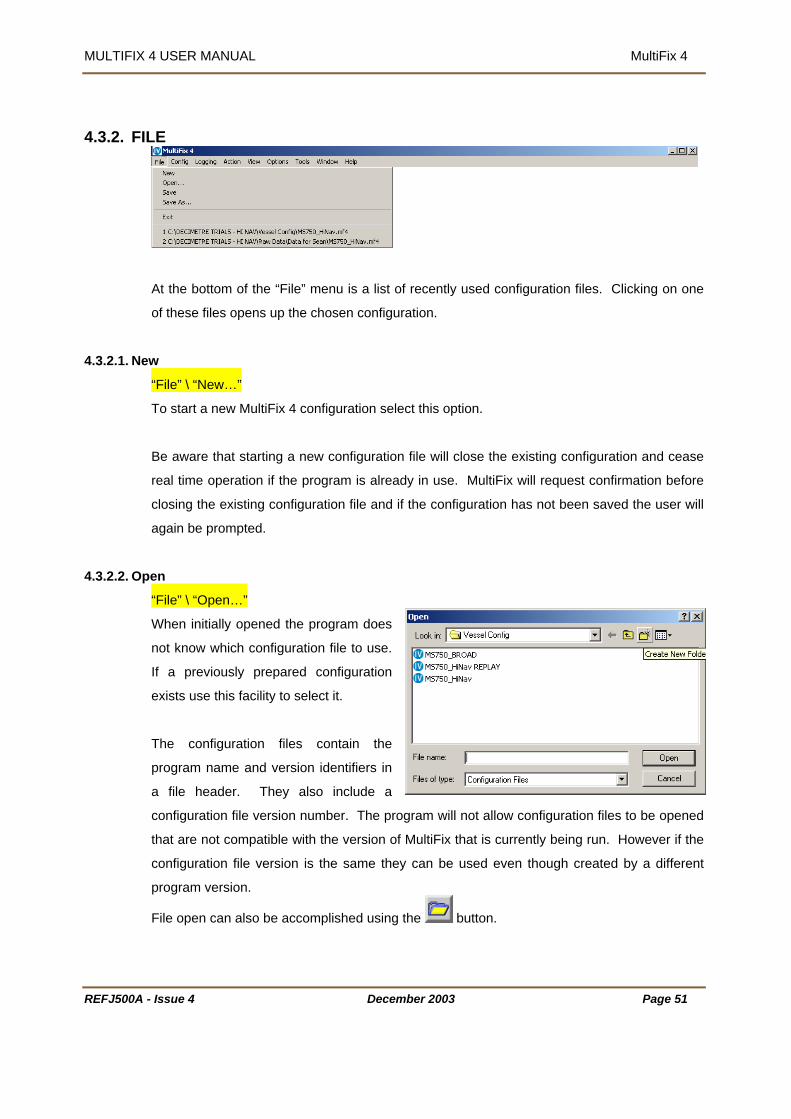
MULTIFIX 4 USER MANUAL MultiFix 4
4.3.2. FILE
At the bottom of the “File” menu is a list of recently used configuration files. Clicking on one
of these files opens up the chosen configuration.
4.3.2.1. New
“File” \ “New…”
To start a new MultiFix 4 configuration select this option.
Be aware that starting a new configuration file will close the existing configuration and cease
in use. MultiFix will request confirmation before
he configuration has not been saved the user will
4.3.2.2. Open
real time operation if the program is already
closing the existing configuration file and if t
again be prompted.
“File” \ “Open…”
When initially opened the program does
not know which configuration file to use.
a previously prepared configuration
facility to select it.
he configuration files contain the
onfiguration file version number. The program will not allow configuration files to be opened
complished using the
If
exists use this
T
program name and version identifiers in
a file header. They also include a
c
that are not compatible with the version of MultiFix that is currently being run. However if the
configuration file version is the same they can be used even though created by a different
program version.
File open can also be ac button.
REFJ500A - Issue 4 December 2003 Page 51

MULTIFIX 4 USER MANUAL MultiFix 4
4.3.2.2.1.Save
“File” \ “Save”
The configuration file is not automatically saved when changes are made. This facility is
therefore used to update the configuration file with the current settings. If the set-up is being
undertaken for the first time and the configuration file does not have an identity, the use of
“File” \ “Save” will open the Save As dialogue where a file name must be entered. Once a
configuration file has been named, the use of “File” \ “Save” performs a save without calling
up the Save As dialogue.
The name of the current configuration file appears in the application workspace title bar. If
configuration changes are made that have not been saved, that file name has an “*”
appended to it. After using File \Save the “*” is removed. File saving can also be
accomplished using the button.
4.3.2.3. Save As
“File” \ “Save As…”
If the latest configuration is to be saved without overwriting the current configuration file use
ile” \ ”Save As…” option. This gives the option to create a new file leaving the previous
ediately uses the new file as the current configuration file.
4.3.2.4. Exit
the “F
file intact. The program imm
The Save As dialogue requires the operator to enter a name for the new configuration file. If
an existing file name is entered the program will overwrite that file.
“File” \ “Exit”
This exit route is immediate if no configuration file is loaded.
Confirmation is required if a configuration file is in use. The user will be prompted to save the
the
configuration if they have not already done so.
If the program is exited using button when the current configuration has not been
saved, a dialogue is presented asking whether to save the configuration prior to exit or
whether to cancel the exit. If there have been no configuration changes then the program will
terminate immediately.
REFJ500A - Issue 4 December 2003 Page 52

MULTIFIX 4 USER MANUAL MultiFix 4
REFJ500A - Issue 4 December 2003 Page 53
4.3.3. CONFIGURE
SkyFix Decoder Calc Output
Setup001 - MultiFix 4 MultiFix3
New…
1 <name> Edit…Delete
SettingsSkyFix XP…
File Config Logging Action View Options Tools Window Help
StandardNMEADGPS_ISUTM
New
1 <name> Edit…Delete
IO GPS Rx...
Output
Comm…Socket…
Setup001 - Fix
New…
1 <name> Edit…Delete
File Config Logging Action View Options Tools Window Help
1 <name> Edit…Delete
New…
1 <name> Edit…Delete
DGPS Calc
4.3.3.1. IO
“Config” \ “IO”
The “P2/94 Output” will only be visible if “P2/94” has been enabled in the “Options” menu.
4.3.3.1.1.Comm
“Config” \ “IO” \ “Comm…”
Earlier it was explained that the “Programs” / “MultiFix 4 Vx.xx” / “IO Config” applet needed to
be run after installation to define what ports the computer has available (see section 3.4 on
page 13). The parameters selected there determine the dialogue box that is presented when
“Config” \ “IO” \ “Comm…” is selected.
Highlight one of the ports to be used and click
[Edit]. This opens another dialogue box for
setting the port parameter settings.
Click the [Enable] button to activate the port
and set the Baud Rate, Data Bits, Parity and
Stop Bits.

MULTIFIX 4 USER MANUAL MultiFix 4
REFJ500A - Issue 4 December 2003 Page 54
4.3.3.1.2.Sockets
“Config” \ “IO” \ “Socket…”
To be able to distribute and receive data over a network via sockets assumes each computer
has Transmission Control Protocol / Internet Protocol (TCP/IP) installed. Sockets have the
advantage over COM ports in that two or more programs can access the same data.
Sockets can transfer data between programs running on different computers or between two
or more programs running on the same computer. (If a standalone (non-networked) computer
running Windows NT is used and the data is to be shared between multiple programs running
on that PC then the MS Loopback Adapter network adapter must be installed).
The TCP/IP protocol is a family of protocols that allow Internet data communication. Included
in that family are two transport layer protocols, the Transport Control Protocol (TCP) and the
User Datagram Protocol (UDP).
The Transport Control Protocol establishes sessions between a Server and however
many Clients that are accessing that Server. There is continual presence checking
and acknowledging between each Server/Client pairs with messages always received
in the order they were issued. A Server does not have control of the number of
Clients that access the socket on which data is being presented. (It is often
perceived that the Server provides data and the Client receives data, but once the
connection is established the link is two-way).
The User Datagram Protocol does not have the end-to-end checking overhead of the
TCP. Instead packets of data are simply issued to the Internet in either broadcast
mode, where any networked computer on the LAN can receive them, or in addressed
mode where the data packets have headers specifying the addressees for whom the
packets are intended. There is no guarantee with this protocol that the messages will
arrive in the order they were issued. When setting up “Ribbons” to output datagrams
a time interval can be specified to prevent data becoming corrupted, see section
7.3.2.2. on “Ribbons”. Broadcast datagrams cannot pass routers linking Local Area
Networks (LAN) unless specifically configured.
For most situations where Local Area Networks are involved Server / Client TCP sockets are
the best choice Internet transport protocols.
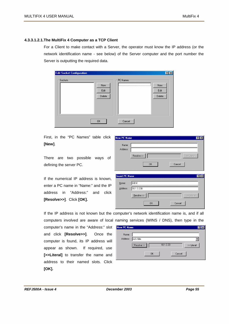
MULTIFIX 4 USER MANUAL MultiFix 4
.The MultiFix 4 Computer as a TCP Client
For a Client to make contact with a Server, the operator must know the IP address (or the
network identification name - see below) of the Server computer and the port number the
Server is outputting the required data.
4.3.3.1.2.1
server PC.
nd the IP
ddress in “Address:” and click
[Resolve>>]. Click [OK].
If the IP address is not known but the computer’s network identification name is, and if all
computers involved are aware of local naming services (WINS / DNS), then type in the
computer’s name in the “Address:” slot
and click [Resolve>>]. Once the
computer is found, its IP address will
appear as shown. If required, use
[>>Literal] to transfer the name and
address to their named slots. Click
[OK].
First, in the “PC Names” table click
[New].
There are two possible ways of
defining the
If the numerical IP address is known,
enter a PC name in “Name:” a
a
REFJ500A - Issue 4 December 2003 Page 55

MULTIFIX 4 USER MANUAL MultiFix 4
It is normal in a network for computers to be allocated new IP addresses when the PC is
the Client PC has a numerical entry for the address and the Server’s address
obtain the Server PC’s current address.
le click [New].
nter the number of the port on which the Server PC is
fault name if required.
4.3.3.1.2.2
the MultiFix computer is to be a server then there is no
an be seen in the window called up by “View” \
on. Click [OK] to exit.
restarted. If
has changed, it will not be able to re-locate it. If the Client PC has the name of the Server PC
in the address slot, it will automatically search to re-locate the Server PC by name. Assuming
it is found, the Client PC will
In the “Sockets” tab
Now check the “Client” radio button and select the ”PC
Name:” of the server.
E
presenting the data. Change the socket’s de
.The MultiFix 4 Computer as a TCP Server
If
need to add the MultiFix computer to the PC table; the
program already knows the computer’s IP address. This
c
“Sockets”.
In the “Sockets” table click [New]. Give the socket a
name and enter the Port number that the data will be
output
REFJ500A - Issue 4 December 2003 Page 56

MULTIFIX 4 USER MANUAL MultiFix 4
REFJ500A - Issue 4 December 2003 Page 57
4.3.3.1.2.3.Datagrams
It was explained in section 4.3.3.1.2 that the User Datagrams Protocol allows packets of data
to be broadcast or to be sent to specific addresses without the overheads associated with the
Transport Control Protocol.
BROADCASTING
MultiFix 4 cannot give multiple addresses to packets of data so if information is to be made
available to more than one computer in datagrams it must be broadcast on a particular port.
A computer that is broadcasting on a port also listens to all data packets that are received on
that port.
DATAGRAMS TO/FROM A SPECIFIC PC
To transmit to or to receive from a specific computer, (which may itself be broadcasting), a PC
must be set up with a datagram socket where the port number and the PC are identified.
To broadcast datagram packets, click the “Datagram” radio
button and select “Broadcast” from the “PC Name:” list.
To target one specific PC requires that the Internet address
of that PC should already have been identified. See
Section 4.3.3.1.2.1 on page 55 for an explanation of adding
PCs.
Once the PC has been entered in the “PC Names:” table click [New] in the “Sockets” table.
Give the socket a name,
enter the Port number and
in the “PC Name list
select the PC.
Click [OK] to exit.
Having set up sockets, the Edit Socket Configuration dialogue now shows the connection(s).

MULTIFIX 4 USER MANUAL MultiFix 4
REFJ500A - Issue 4 December 2003 Page 58
4.3.3.2. GPS Receiver
“Config” \ “GPS Rx…”
This calls up the Edit GPS Receiver.
Enter a receiver name in the “Name:” box. If this is left blank
MultiFix will automatically assign a suitable name (e.g. 4000
DS (Trimble)). As with other name labels the program does
not use it for receiver recognition purposes.
In the “Type:” section select the receiver that MultiFix 4 is to
use. There are various possible selections.
• Z Family (Ashtech)* are dual frequency receivers.
• DG16 (Ashtech) )* is a single frequency receiver
• G12 (Ashtech) )* is a single frequency receiver
• GG24 (Ashtech) * is a single frequency receiver and is fitted in the Fugro 90964 units
• 4000 Series (Trimble) refers to either a single frequency 4000DS or a dual frequency
SSE/SSI
• MS750 (Trimble) is a dual frequency receiver
• BD750 (Trimble) is a dual frequency receiver
• 5700 (Trimble) is a dual frequency receiver
• BD112 (Trimble)* is a single frequency receiver board fitted to the 90938/F112 SkyFix
decoder.
• DSM212 (Trimble)* is a single frequency receiver.
• DSM (Trimble)* is a single frequency receiver board fitted to 90938/M SkyFix decoder.
• SK8 (Trimble)* is a single frequency receiver board, but not recommended for offshore
work. It has not been tested for full operation.
• Millennium (NovAtel) is a dual frequency receiver
• OEM4 (NovAtel) is a dual frequency receiver
• Receiver Server is used when the data is not live from an external receiver but is taken
from raw data log files.
• Receiver Verify is used for interfacing to the Receiver Verify (RxV) Module.
The Scintillation Filter option allows MultiFix to monitor the tracking of individual SVs. If
symptoms of scintillation are detected the SV is disabled until tracking becomes constant
again, giving a massive reduction in position instabilities. Since this may affect the number of

MULTIFIX 4 USER MANUAL MultiFix 4
available satellites users are advised to operate in Height Aiding mode when the Scintillation
Channel:” section select the port on which the receiver data is input.
he Ancillary Receiver option is used for synchronising GPS measurements over a data link.
asterix is selected, “Configure TSIP” or
ction” menu. This allows the receiver to
onfigured to output the correct data for MultiFix 4. The other Trimble Receivers are
onfigurable using the Yellow box interface (“View” / “GPS” / “Receiver”). Refer to Section
ther manufacturers’ receivers require third party software to configure.
4.3.3.3. Sk ix Decoder
Filter is enabled.
In the “IO
T
This is not currently used.
When one of the receivers marked above with an
“Configure Ashtech” becomes available under the “A
be c
c
4.3.6.4.1
O
yF
“Config” \ “SkyFix Decoder”
The program will automatically take in any type 55 messages received on any RTCM IO
hannel to which it has access, but will only take in Type 1, 2, 3 and 9 messages from
that an RTCM source may contain only
be given an identity and an “IO Channel”
IDs. Each Type 55 message contains Ionospheric delay information from one
reference station. The station ID is also in the message that is transmitted every 30 seconds.
C
Stations ID’s it is configured to accept. It is possible
Type 55 messages. Such a source will still need to
but no station
The sequence cycles through each of the available reference station, so if 7 stations are
contributing Type 55 messages the information for each station will be updated every 3½
minutes.
In the same way, for an XP calculation the correction source will need to be given an identity
and an “IO Channel” but no station IDs. MultiFix will then accept the Fugro Proprietary Type
11, 48, 49 and 50 messages necessary for this mode.
REFJ500A - Issue 4 December 2003 Page 59

MULTIFIX 4 USER MANUAL MultiFix 4
REFJ500A - Issue 4 December 2003 Page 60
4.3.3.3.1.New
“Config” \ “SkyFix Decoder” \ “New…”
Click on “New…” to make a connection to a RTCM
source.
In the New RTCM Input dialogue give the RTCM
source a name and select the “IO Channel:” of the
port that the differential corrections are available
on.
If no name is given MultiFix will assign a suitable
name automatically.
“SkyFix Beams:” contains a drop down list of all
the satellite based Fugro RTCM sources. When
one of those sources is selected, the dialogue is
automatically populated with all the stations that
carried by that system and the [New], [Edit] and
[Delete] buttons are lost.
It is then necessary to switch on any stations to be
used by clicking the check box next to the station’s
name.
If SkyFix-XP mode is to be used then, along with a dual frequency GPS receiver, an RTCM
input must be set up to obtain corrections. To do this enter a “Name”, “IO Channel”, and the
relevant “SkyFix Beam” (Refer to ‘SkyFix-XP Service Description’ or HTUwww.thales-
geosolutions.comUTH for the latest XP availability information). No reference stations should be
selected from the resultant list as only one set of XP corrections are available on each SkyFix
beam. MultiFix will take in these messages as soon as this calculation is set up and “SkyFix-
XP” mode has been checked in the “Config” \ “Calc” \ “Settings” dialogue.
SkyFix-XP corrections are broadcast using the following Fugro proprietary RTCM messages:

MULTIFIX 4 USER MANUAL MultiFix 4
REFJ500A - Issue 4 December 2003 Page 61
Type 11 – Almanac.
Type 48 – Absolute orbit, orbit rate, and clock corrections.
Type 49 – Absolute orbit and clock corrections.
Type 50 - Sub-metre clock corrections
If MultiFix 4 is being used with a non-satellite based RTCM delivery system, or station names
or numbers have been changed, a manually compiled list can be made. To add reference
stations manually in the “Station” table of the New RTCM Input dialogue leave the “SkyFix
Beam:” set to User Defined and click the [New] button.
The program requires the station ID code number. A name is also required for identity
purposes but is not significant in accessing the data.
Assuming the RTCM source is outputting more than
one station, after clicking [OK] to add the station to
the list, repeat the process to add the other required
stations.
If Iono free operation is planned, three criteria must
be met to be viable.
1. A dual frequency receiver must be interfaced to
MultiFix 4.
2. RTCM Type 1, 2 and 3 messages from one or
more reference stations must be available.
3. Type 15 or 55 Ionospheric error information
must also be available from the same RTCM reference stations.
For Premier calculations there is no need to set up 6 reference stations if only one of them
outputs Ionospheric error information as this will be the only station used in that mode.
If a SkyLink calculation is to be used however then both dual and single frequency stations
can be combined. See section 4.3.3.4.3 for more details of Calculation type.
The ID of the type 55 messages is not declared as a station.
If a Mk 5, 90938 or 2403 Decoder is used to supply the RTCM corrections then it is possible
to configure the decoder to output Bit Error Rate and Signal Voltage status information on a
separate port (usually Port 4). If this data is required then check the “Exists” box and select

MULTIFIX 4 USER MANUAL MultiFix 4
the port receiving the data. This in turn activates the “SkyFix Decoder” menu item under
ns”.
Click [OK] to accept the correction source.
If there is more than one RTCM correction delivery system add another new source and set
up using either of the two procedures above.
ssuming the RTCM interface has been established, the messages from the RTCM source
viewed to see the Reference Station numbers that the program is receiving, (see
4.3.3.3.2.E
“View” \ “Correctio
A
can be
Section 4.3.6.3.4.2 page 96).
diting and Deleting
“Config” \ “SkyFix Decoder” \ “<name>” \ “E
With an RTCM source (or sources) now
selected, the name (or names) given to th
under the “New…
dit…” or “Delete”
defined, when “Config” \ “SkyFix Decoder” is
e RTCM source(s) now appears in the sub-menu
” menu item.
If the set up requires changing then highlight the name of the source and then select the
“Edit…” option.
If the RTCM source is no longer in use, again use “Config” \ “SkyFix Decoder” \ “<name>” and
select “Delete”. You will be asked to confirm or cancel the deletion. Be aware that an
inappropriate deletion could severely impact on the correct operation of the program.
REFJ500A - Issue 4 December 2003 Page 62

MULTIFIX 4 USER MANUAL MultiFix 4
REFJ500A - Issue 4 December 2003 Page 63
4.3.3.4. Calculations
“Config” \ “Calc”
ettings 4.3.3.4.1.S
“Config” \ “Calc” \ “Settings…” calls up the dialogue below.
Enter a Trial Point position in the
“Latitude” and “Longitude” fields. This
must be within, at the most, half a degree
of Latitude and Longitude from the users
urrent position.
e the degrees, minutes and seconds
values.
red (or no value at all) then MultiFix will attempt to derive an
pproximate position either from the current calculation, if available, or directly from the GPS
re the GPS
eceiver.
e
y selecting the “User Defined” radio button. This should only be used where the EGM96
c
Both the “Latitude” and “Longitude” fields
allow a flexible form of data entry. The
N/S or E/W can be entered at the start or
end of the value. A space, comma or colon can separat
If the incorrect Trial point is ente
a
Receiver.
In order to obtain a position from the GPS Receiver position outputs should be enabled on the
data port being used by MultiFix. See Section 4.2.4 for details of how to configu
R
MultiFix includes the EGM96 Geoid / Spheroid separation model. By default this model is
used for all calculations. The separation is computed every epoch and the figure used within
the calculation is the exact figure for the current location.
It is also possible to disable this model and apply your own Geoid / Spheroid separation valu
b

MULTIFIX 4 USER MANUAL MultiFix 4
model is not suitable, such as on locked waterways where the sea level is not coincident with
the local Geoid.
The Geoidal height based on the Geoid / Spheroid separation is used in all displays in
ultiFix unless otherwise stated. However, using the wrong Geoid / Spheroid separation will
nter the height of the antenna above the ships water line, or Mean Sea Level (MSL), in
ht SD is dependant on the confidence of the initial antenna height
easurement and the expected variation in antenna height due to vessel movement caused
ked or inland
aterways, the mean water level may be many metres above or below the Mean Sea
Level/Geoid.
vation” table is “Mask” and “Delta”. “Mask” sets the minimum elevation at which a
m. Do not set an elevation mask in this dialogue lower than
the elevation mask used in the GPS receiver. Setting a lower mask does not change the
higher
e suffering from poor signal to noise ratios.
When using a SkyFix-XP calculation the “Elevation Mask” is hard coded to 5° and the “Delta”
to 0° in order to have a minimum of 5 SV’s available. Setting the “Elevation Mask” and “Delta”
will change the mask values for the SkyFix and SkyFix Premier calculations only.
When setting up a SkyLink Mode calculation MultiFix will only use the single frequency
corrections for stations that are within this range. This allows the user to add single frequency
stations that are close to the work area (e.g. DeltaFix and IALA beacon stations), and are not
significantly affected by differential ionospheric delays, into a dual frequency calculation. The
“SkyLink Critical Distance” sets the threshold distance that MultiFix will use to switch from
single to dual frequency calculation for each individual station. The default value is 300km.
M
only affect the calculation process if height aiding is enabled.
E
“Height above MSL” box. This is approximately equal to the Geoid. The “Height above MSL:”
and the “Height SD:” are used if the calculation is selected to be altitude aided, see 4.3.3.4.3.
The smaller the “Height SD:” value the higher weight is given to the “Height above MSL:”
value. The Heig
m
by swell and changes in draught. Remember, when surveying on landloc
w
In the “Ele
satellite will be used by the progra
receiver configuration. Setting a higher mask may be useful if SVs at slightly
elevations ar
“Delta” is the number of degrees above the minimum elevation a satellite must be before it is
fully weighted in a computation.
REFJ500A - Issue 4 December 2003 Page 64

MULTIFIX 4 USER MANUAL MultiFix 4
REFJ500A - Issue 4 December 2003 Page 65
The Trial Point is used when the Offsets Window is viewed. One of the options when right
clicking on that window is to have the centre point at a fixed co-ordinate and to view the
calculated positions with reference to that trial point. In this case the position will need to be
entered with the highest possible precision to obtain realistic offset views.
If the “SkyFix premier” box is checked the SkyFix Premier dual frequency positioning mode is
enabled.
If the “SkyFix-XP” box is checked the XP positioning mode is enabled. This reveals the
additional menus “Config” / “Calc” / “SkyFix-XP…” (See section 4.3.3.4.2), “View” \
“Corrections” \ “Orbit Data” (See Section 4.3.6.5.1), and “View” \ “Calc” \ “XP Offsets” (See
section 4.3.6.6.3).
When exiting XP or Premier positioning mode the following warning is issued:
4.3.3.4.2.SkyFix-XP
“Config” / “Calc” / “SkyFix-XP…”
This menu becomes available when SkyFix-XP mode is enabled in “Config” \ “Calc” \
“Settings”.
The XP calculation will automatically start when XP mode is selected, assuming a valid GPS
Receiver and decoder have been configured.
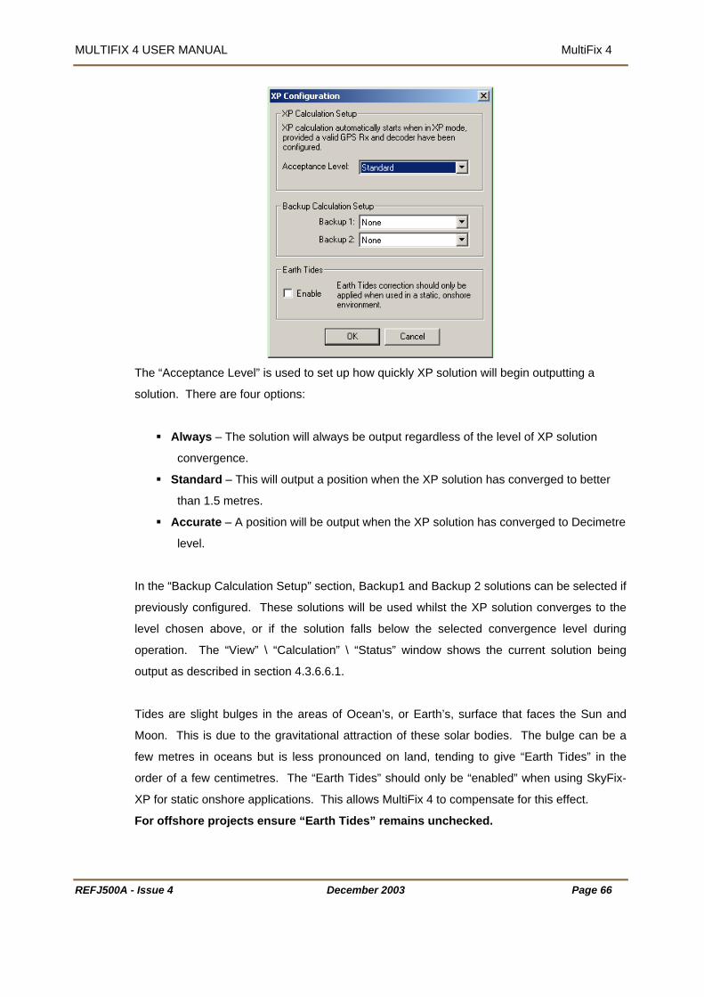
MULTIFIX 4 USER MANUAL MultiFix 4
REFJ500A - Issue 4 December 2003 Page 66
The “Acceptance Level” is used to set up how quickly XP solution will begin outputting a
solution. There are four options:
Always – The solution will always be output regardless of the level of XP solution
convergence.
Standard – This will output a position when the XP solution has converged to better
than 1.5 metres.
Accurate – A position will be output when the XP solution has converged to Decimetre
level.
In the “Backup Calculation Setup” section, Backup1 and Backup 2 solutions can be selected if
previously configured. These solutions will be used whilst the XP solution converges to the
level chosen above, or if the solution falls below the selected convergence level during
operation. The “View” \ “Calculation” \ “Status” window shows the current solution being
output as described in section 4.3.6.6.1.
Tides are slight bulges in the areas of Ocean’s, or Earth’s, surface that faces the Sun and
Moon. This is due to the gravitational attraction of these solar bodies. The bulge can be a
few metres in oceans but is less pronounced on land, tending to give “Earth Tides” in the
order of a few centimetres. The “Earth Tides” should only be “enabled” when using SkyFix-
XP for static onshore applications. This allows MultiFix 4 to compensate for this effect.
For offshore projects ensure “Earth Tides” remains unchecked.

MULTIFIX 4 USER MANUAL MultiFix 4
ew Calculation 4.3.3.4.3.N
“Config” \ “Calc” \ “DGPS Calc” \ “New…”
provides the dialogue opposite.
The dialogue will contain all the
sed in forming the solution. If no
orrected stand-alone solution. If no name is given
ultiFix will automatically generate an appropriate name for the computation based on the
lation required.
Standard” creates a single frequency DGPS solution using the Klobachar Ionospheric
ions will only be available if SkyFix Premier mode is enabled in “Config” \
“Premier” creates an Iono-Free DGPS solution. It presumes there is access to dual
quency data from a GPS receiver and Type 1 and Type 55 messages (skyfix Premier) from
SkyLink” allows MultiFix to add single frequency stations close to the user to a dual
page. This function allows users to mix single
nd dual frequency corrections in a single calculation.
RTCM reference station names
entered when defining the RTCM
source(s). If the same station was
selected twice it will appear twice.
Give the Calculation a name and
select the reference stations to be
u
reference stations are selected the
program will produce a non-differentially c
M
configuration of the solution
e.g. Network - L1L2 – H+, meaning a network solution using L1 and L2 with height aiding
enabled.
Click the type of calcu
“
model.
The following two opt
“Calc” \ “Settings”.
fre
at least one of the selected reference station(s). A “Premier” solution will not use corrections
from reference stations where only Type 1 or Type 55 messages are received, both must be
available.
“
frequency calculation. Selection is based on the range to the station, as defined under the
“Config” \ “Calc” \ “Settings…” configuration
a
REFJ500A - Issue 4 December 2003 Page 67
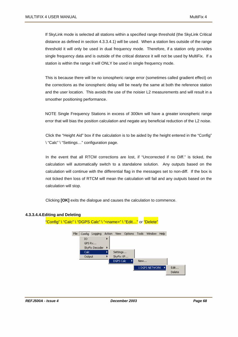
MULTIFIX 4 USER MANUAL MultiFix 4
REFJ500A - Issue 4 December 2003 Page 68
If SkyLink mode is selected all stations within a specified range threshold (the SkyLink Critical
distance as defined in section 4.3.3.4.1) will be used. When a station lies outside of the range
threshold it will only be used in dual frequency mode. Therefore, if a station only provides
single frequency data and is outside of the critical distance it will not be used by MultiFix. If a
station is within the range it will ONLY be used in single frequency mode.
This is because there will be no ionospheric range error (sometimes called gradient effect) on
the corrections as the ionospheric delay will be nearly the same at both the reference station
and the user location. This avoids the use of the noisier L2 measurements and will result in a
smoother positioning performance.
NOTE Single Frequency Stations in excess of 300km will have a greater ionospheric range
error that will bias the position calculation and negate any beneficial reduction of the L2 noise.
Click the “Height Aid” box if the calculation is to be aided by the height entered in the “Config”
\ “Calc” \ “Settings…” configuration page.
In the event that all RTCM corrections are lost, if “Uncorrected if no Diff.” is ticked, the
calculation will automatically switch to a standalone solution. Any outputs based on the
calculation will continue with the differential flag in the messages set to non-diff. If the box is
not ticked then loss of RTCM will mean the calculation will fail and any outputs based on the
calculation will stop.
Clicking [OK] exits the dialogue and causes the calculation to commence.
4.3.3.4.4.Editing and Deleting
“Config” \ “Calc” \ “DGPS Calc” \ “<name>” \ “Edit…” or “Delete”

MULTIFIX 4 USER MANUAL MultiFix 4
REFJ500A - Issue 4 December 2003 Page 69
Once a calculation(s) has been defined the “Config” \ “Calc” \ “DGPS Calc” sub-menu
contains the name (or names) of the calculation(s). If a name is highlighted the calculation
can be “Edited…” or “Deleted”. Deletion requires a confirmation.
Assuming the set up has been accomplished correctly the program will now attempt to
receive data and form a position solution(s).
At this point it is recommended that the configuration file be saved (See section 4.3.2.2.1).
4.3.3.5. Output
“Config” \ “Output”
If a position is to be supplied to another computer then an output must be defined.
Reference has already been made in Section 3.4.2 on page 13 to the fact that MultiFix 4 must
have accessed the *.zpo library files before it can create the output formats listed below.
MultiFix 4 can create:
9 different Standard outputs, Trimble, DNAV, DNAV – Nautis Modification, ZeroLink,
Fugro UKOOA, Geco UKOOA, Geco UKOOA Version 2, Fugro XP Expanded and
Fugro XP Concise.
10 different NMEA outputs, GGA, GGA + VTG, GLL, RTK, ZDA, DPGGA, GGA
(LDA), GSA, GST and GSV
Note that the RTK sentence is a Fugro proprietary sentence. It has been included for
future development but should not be used until Real Time Kinematic computations
are being performed within MultiFix 4. The facility to create an RMC message is
described under the User Modified section see page 73.
2 different Projection Grid (UTM) outputs known as Syledis and GEM 80 DP
1 Propriety XML Data output called DGPS_IS

MULTIFIX 4 USER MANUAL MultiFix 4
The DPS_IS sentence is a Fugro proprietary sentence. It has been included for
ith Fugro monitoring software.
is a time tag in a position output string, the time output will be the
me of the fix, i.e. when the position calculation was performed, unless otherwise stated. This
x 4 does not predict the position
e time of output. (This does not apply to the NMEA ZDA sentence
here the time in the sentence is that of the moment of output). The time standard used in
use w
APPENDIX A - DATA OUTPUT STRINGS on page 316 has descriptions of all the output
formats.
Note: When there
ti
may be up to 1 second old by the time of output. MultiFi
contained in the string to th
w
each output that contains time will be as defined by the format of the output, i.e. UTC or GPS
time.
REFJ500A - Issue 4 December 2003 Page 70
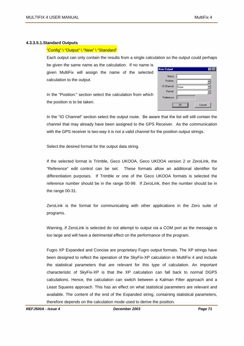
MULTIFIX 4 USER MANUAL MultiFix 4
tandard Outputs 4.3.3.5.1.S
“Config” \ “Output” \ “New” \ “Standard”
esults from a single calculation so the output could perhaps
e given the same name as the calculation. If no name is
me of the selected
ch
the “IO Channel” section select the output route. Be aware that the list will still contain the
S Receiver. As the communication
PS receiver is two-way it is not a valid channel for the position output strings.
Select th d form
If the se format sion 2 or ZeroLink, the
“Referen it contr
differentiation purposes. elected the
reference number should be in the range 00-99. If ZeroLink, then the number should be in
the range
ZeroLink
programs.
Warning, oLink is a COM port as the message is
too large ill have f the program.
ugro XP Expanded and Concise are proprietary Fugro output formats. The XP strings have
type of calculation. An important
statistical parameters are relevant and
available. The content of the end of the Expanded string, containing statistical parameters,
therefore depends on the calculation mode used to derive the position.
Each output can only contain the r
b
given MultiFix will assign the na
calculation to the output.
In the “Position:” section select the calculation from whi
the position is to be taken.
In
channel that may already have been assigned to the GP
with the G
e desire at for the output data string.
lected is Trimble, Geco UKOOA, Geco UKOOA ver
ce” ed ol can be set. These formats allow an additional identifier for
If Trimble or one of the Geco UKOOA formats is s
00-31.
is the format for communicating with other applications in the Zero suite of
if Zer selected do not attempt to output via
and w a detrimental effect on the performance o
F
been designed to reflect the operation of the SkyFix-XP calculation in MultiFix 4 and include
the statistical parameters that are relevant for this
characteristic of SkyFix-XP is that the XP calculation can fall back to normal DGPS
calculations. Hence, the calculation can switch between a Kalman Filter approach and a
Least Squares approach. This has an effect on what
REFJ500A - Issue 4 December 2003 Page 71

MULTIFIX 4 USER MANUAL MultiFix 4
The Concise string gives users the option to use a basic position & QC output, the Expanded
more satellite related QC information.
4.3.3.5.2.A ts
string is required to have access to
Click [OK] to activate the output.
pproved NMEA Sentence Outpu
“Config” \ “Output” \ “New” \ “NMEA”
s with the Standard outputs give the output a
ame”, a source computation in “Position” and
the “Format” slot select the output format(s)
quired.
Sentence Formatter
GGA = Global Positioning System Fix Data
VTG = Course over Ground and Ground Speed
GLL = Geographic Position – Latitude/Longitude
RTK = Real Time Kinematic (not approved, Fugro proprietary, should not
be used until MultiFix 4 supports RTK computations).
ZDA = UTC Time and Date
DPGGA = IMCA DGPS DP Interfacing Format, a standard format providing
suitable data for DP systems.
odified version of the GGA string for interfacing to
specific systems that cannot handle a latency figure of more than
10 seconds.
GSA = GNSS DOP and Active Satellites
GST = GNSS Pseudorange Error Statistics
GSV = GNSS Satellites in View
he “Interval” option allows the user to specify an interval (in seconds) between GGA outputs,
to be used if an output rate of less than 1Hz is required.
Please note that setting is an actual interval, the software will supply the first available fix after
the specified interval, so if the calculation processes is running slowly the difference in times
tags may not equate to exactly the specified interval.
A
“N
assign an “I/O Channel” for output.
In
re
GGA (LDA) = This is a m
T
REFJ500A - Issue 4 December 2003 Page 72
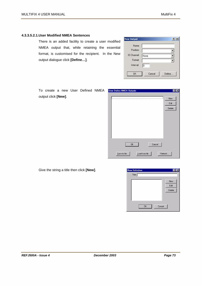
MULTIFIX 4 USER MANUAL MultiFix 4
4.3.3.5.2.1.User Modified NMEA Sentences
ty to create a user modified
hile retaining the essential
r the recipient. In the New
ne…].
utput click [New].
ck [New].
There is an added facili
NMEA output that, w
format, is customised fo
output dialogue click [Defi
To create a new User Defined NMEA
o
Give the string a title then cli
REFJ500A - Issue 4 December 2003 Page 73
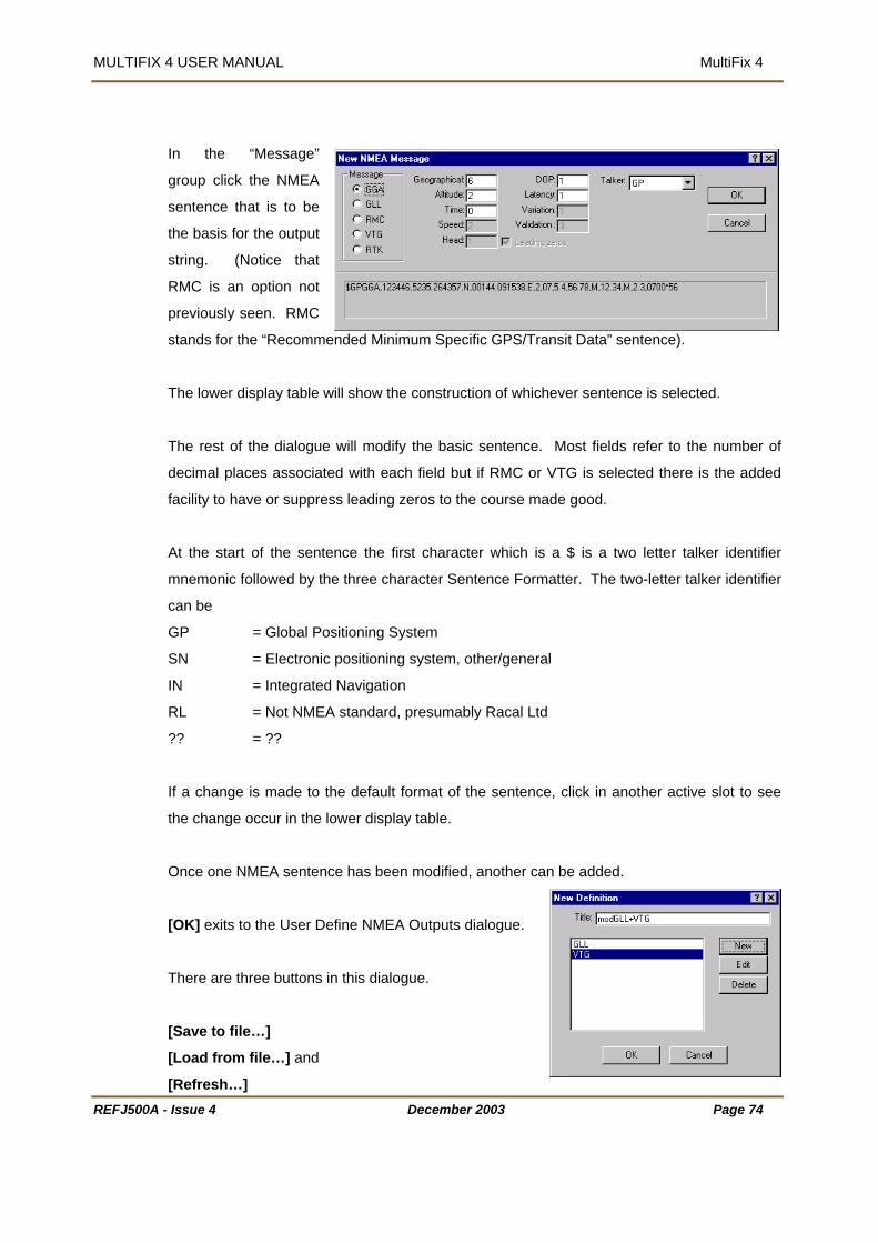
MULTIFIX 4 USER MANUAL MultiFix 4
In the “Message”
group click the NMEA
sentence that is to be
MC is an option not
tands for the “Recommended Minimum Specific GPS/Transit Data” sentence).
s selected.
he rest of the dialogue will modify the basic sentence. Most fields refer to the number of
decimal places associated with each field but if RMC or VTG is selected there is the added
facility to have or suppress leading zeros to the course made good.
At the start of the sentence the first character which is a $ is a two letter talker identifier
mnemonic followed by the three character Sentence Formatter. The two-letter talker identifier
can be
GP = Global Positioning System
SN = Electronic positioning system, other/general
IN = Integrated Navigation
RL = Not NMEA standard, presumably Racal Ltd
?? = ??
If a change is made to the default format of the sentence, click in another active slot to see
the change occur in the lower display table.
Once one NMEA sentence has been modified, another can be added.
[OK] exits to the User Define NMEA Outputs dialogue.
There are three buttons in this dialogue.
[Save to file…]
[Load from file…] and
[Refresh…]
the basis for the output
string. (Notice that
R
previously seen. RMC
s
The lower display table will show the construction of whichever sentence i
T
REFJ500A - Issue 4 December 2003 Page 74

MULTIFIX 4 USER MANUAL MultiFix 4
[Save to file…] opens the Save definition to file dialogue. Enter a name for the Fugro
efinition Format file and click [Open]
ogue. The current *.rdf files will be
defined and saved user output sentences click [Open].
/ loaded, its title is added to the
ted for output.
D
[Load from file…] opens the Load definition from file dial
listed. To revert to previously
[Refresh…] deletes all User Defined Outputs.
Once a user defined NMEA output has been created
approved NMEA sentence list so it can thereafter be selec
REFJ500A - Issue 4 December 2003 Page 75

MULTIFIX 4 USER MANUAL MultiFix 4
4.3.3.5.3.UTM Outputs
“Config” \ “Output” \ “New” \ “UTM”
a “Name”, a source computation in “Position” and assign
the “Projection” table if “UTM” is clicked the co-
out,
di id. There is no ellipsoid/datum
4.3.3.5.4.Editing and Deleting
As with the Standard and NMEA outputs give the output
an “I/O Channel” for output.
Select the required “Format” (“Syledis” or “GEM 80 DP”)
In
ordinates in the string will be for the UTM Zone relevant
to the current position.
If “TM” is clicked the edit control slots, which are shown
greyed become active and the parameters can be
defined.
Grid co-or nates will be based on the WGS 84 ellipso
transformation facility in MultiFix.
“ na
O ce an ou ut has be , as well as having
ew…” also has the output name (or names). If a name is highlighted, the calculation can
Config” \ “Output” \ “< me>” \ “Edit…” or “Delete”
n tp en defined the “Config” \ “Output” sub-menu
“N
be “Edited…” or “Deleted”. Deletion requires a confirmation.
REFJ500A - Issue 4 December 2003 Page 76

MULTIFIX 4 USER MANUAL MultiFix 4
4.3.3.6. P2/94 Output
“Config” \ “P2/94 Output”
The “P2/94 Output” will only be visible if “P2/94” has been enabled in the “Options” menu.
GPS measurements, ephemeris and RTCM
at is used for the exchange of raw positioning
is recommended by UKOOA for general use in the Oil and Gas, Exploration and
Production industry.
The full P2/94 format is extensive and covers a wide-range of equipment. MultiFix 4 only
utputs P2/94 records that are relevant to positioning, these are as follows:
Observations (## = Observation Type*)
s continuation record (## = Observation Type*)
ated GPS ephemerides & clock
6320 Updated GPS UTC parameters
6321-22 Updated GPS ionospheric model parameters
##22 – GPS carrier-phase ##23 – GPS instantaneous Doppler frequency
red the GPS Rx and, if T65 records are required, a
a P2/94 output.
MultiFix 4 has the capability to output raw
corrections in P2/94 format. The P2/94 form
data and
o
T55## Inter-event network GPS
T56## Network GPS Observation
T6310-17 Upd
T
T
T65## Inter-event Differential correction data (## is the differential Correction Source
(DCS) Identifier) RTCM Type 1, Type 2 and Type 3 messages.
*Observation Type: ##20 – GPS pseudorange, clock bias per receiver per measurement
It is necessary to have already configu
SkyFix decoder as well prior to creating
REFJ500A - Issue 4 December 2003 Page 77

MULTIFIX 4 USER MANUAL MultiFix 4
As with the Standard outputs give the output
a “Name”, and assign an “I/O Channel” for
output.
Next select the differential rence stations
that are required to be output by clicking
[New].
in the SkyFix decoder set-
p will now be available in the
pdown box.
Select a station and then in the “User Def ID” enter a unique ID number to a maximum of 99
ultiFix will not allow duplicate ID’s). The ID does not have to represent the SkyFix ID, but is
ted
e station in the list in the
dit P2/94 Output” dialogue and click
it].
The “Edit ID” dialogue will appear. Make the necessary changes and click [OK] when
k [OK] to activate the output and complete the set-
.
refe
All the reference stations that were
selected
u
dro
(M
used to identify the individual reference stations in the P2/94 T65 records. Once comple
select [OK]. This process has to be repeated for each reference station that is to be included
in the P2/94 output.
To edit a station already included,
highlight th
“E
[Ed
completed.
From the “Edit P2/94 Output” dialogue clic
up. By clicking [Cancel] any changes will not be saved
REFJ500A - Issue 4 December 2003 Page 78

MULTIFIX 4 USER MANUAL MultiFix 4
4.3.4. LOGGING
Edit StartPauseResumeStop
Setup001 - MultiFix 4 MultiFix3 File Config Logging Action View Options Tools Window Help
ZeroRINEX
EditStartPauseResumeStop
Edit StartPauseResumeStop
Edit StartPauseResumeStop
Setup001 - Fix
File Config Logging Action View Options Tools Window Help
EditStartPauseResumeStop
EditStartPauseResumeStop
ending on the current state of logging.
, if logging is ongoing it will be “Pause”
sume” and “Stop”.
he Rinex Logging menu will only be visible if “RINEX” has been enabled under the options
4.3.4.1. Ze
The Logging menu items shown above will change dep
If no logging is taking place it will be “Edit” and “Start”
and “Stop” and if logging is paused it will be “Re
T
menu.
ro
“Logging” \ “Zero“
These files can be read by LOGPUMP (See Section 8)
back into MultiFix regenerating pseudo-real time
Mu iFix to QUAL 2 or POSITIONVIEW
oftware.
4.3.4.1.1.E
Zero log files can also be logged.
where raw data can replayed and directed
positions. Those positions can then be output from lt
s
It is therefore possible for recoded real-time positions to be compared with regenerated
positions.
dit
“Logging” \ “Zero” \ “Edit” calls up the
dialogue shown.
Select the type of logging required.
Note there are not separate raw and
position files, the Zero Log (*.zer) files
can contain both raw measurement and position data.
REFJ500A - Issue 4 December 2003 Page 79
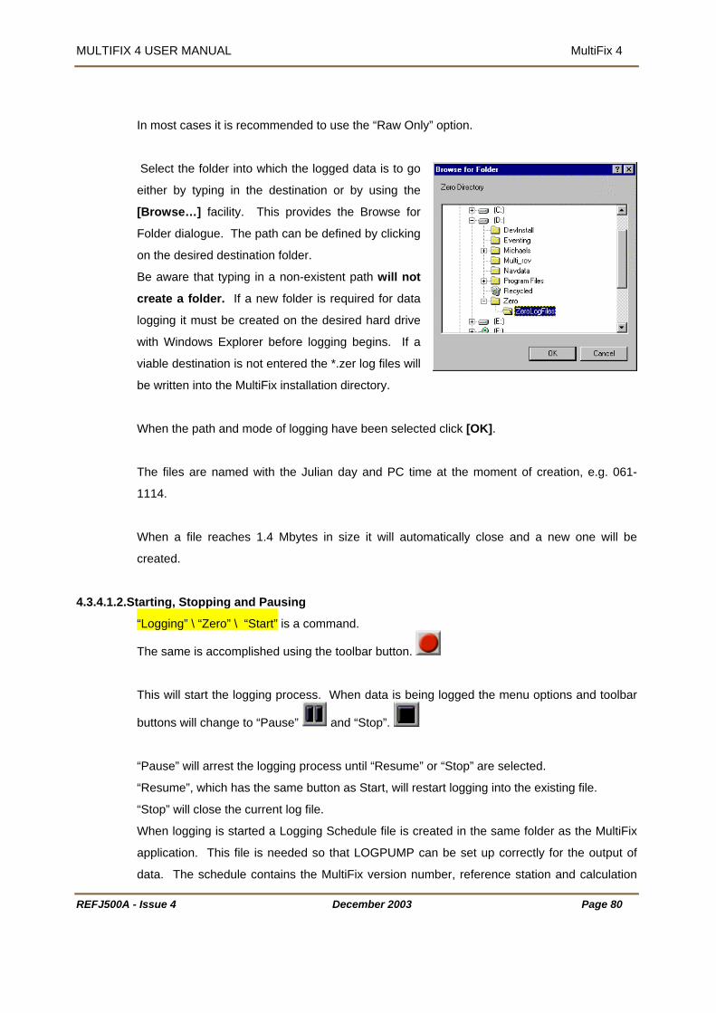
MULTIFIX 4 USER MANUAL MultiFix 4
In most cases it is recommended to use the “Raw Only” option.
Select the folder into which the logged data is to go
either by typing in the destination or by using the
n the desired destination folder.
ware that typing in a non-existent path will not
a new folder is required for data
gging it must be created on the desired hard drive
with Windows Explorer before logging begins. If a
The files are named with the e at the moment of creation, e.g. 061-
tes in size it will automatically close and a new one will be
4.3.4.1.2.S
[Browse…] facility. This provides the Browse for
Folder dialogue. The path can be defined by clicking
o
Be a
create a folder. If
lo
viable destination is not entered the *.zer log files will
be written into the MultiFix installation directory.
When the path and mode of logging have been selected click [OK].
Julian day and PC tim
1114.
When a file reaches 1.4 Mby
created.
tarting, Stopping and Pausing
“Logging” \ “Zero” \ “Start” is a command.
The same is accomplished using the toolbar button.
This will start the logging process. When data is being logged the menu options and toolbar
and “Stop”. buttons will change to “Pause”
“Pause” will arrest the logging process until “Resume” or “Stop” are selected.
logging is started a Logging Schedule file is created in the same folder as the MultiFix
“Resume”, which has the same button as Start, will restart logging into the existing file.
“Stop” will close the current log file.
When
application. This file is needed so that LOGPUMP can be set up correctly for the output of
data. The schedule contains the MultiFix version number, reference station and calculation
REFJ500A - Issue 4 December 2003 Page 80

MULTIFIX 4 USER MANUAL MultiFix 4
status information. There is only one file so if logging is stopped and then re-started the
existing file is overwritten. This means that if configuration changes have been made
etween one log session and subsequent log sessions the Logging Schedule file will only be
le and keep a note of the *.zer log files to
hich it relates. Do not make configuration changes while logging is on going.
4.3.4.2. Rin
b
relevant for the last session. Therefore, if changes are to be made after logging is stopped
use Explorer to make a copy of the Schedule fi
w
When being archived or when being forwarded for replay analysis, the configuration files
(including the schedule file) should be kept with the log files.
ex
“Logging” \ “Rinex“
MultiFix 4 has the capability to log raw GPS observation in the RINEX (Receiver Independent
a final fix or for a post-processed RTK solution.
same day
Y is the year
e, either o for observation files or n for navigation files.
s and file names based on the information
ultiFix is a letter and will increase automatically
ame day.
rvation (*.xxo) and navigation files (*.xxn).
Exchange) format. This is used to collect data for carrier phase post processing; typical
usage is for verification after
MultiFix will automatically generate file names following the standard naming convention, as
follows:
SSSSDDDH.YYT Where:
SSSS is the four character site identifier, this is user defined
DDD is the Julian day of year
H is a letter to differentiate between multiple files from the
Y
T is the file typ
MultiFix will automatically generate the file
provided. The file differentiator (H) used by M
when multiple sessions are conducted on the s
MultiFix will generate both obse
REFJ500A - Issue 4 December 2003 Page 81

MULTIFIX 4 USER MANUAL MultiFix 4
4.3.4.2.1.Edit
“Logging” \ “Rinex” \ “Edit” calls up the dialogue shown.
Certain information is essential for the logging
process. A unique 4-letter site identifier must
be set which is used in the subsequent file
name. Care should be taken not to duplicate
the site name or to change it once it has been
assigned to a specific locale.
ich the logged data is
go either by typing in the destination in the
se…] facility.
ry integer number of seconds past the hour. Therefore a setting of 30
econds will write a measurement on every minute and at 30 seconds past every minute.
ds should be
ld be selected.
he “Measurements” section allows the user to select what measurements are required. In
ost cases all measurements should be selected.
B a dual frequency receiver and antenna must be used to log L2 data.
he “Log For” options allow the user to define a predetermined file length based on time.
y selecting “Period” and an associated length of time from the radio buttons MultiFix will only
e selected period.
Selecting “Indefinite” will force MultiFix to write sequential files of the defined period. This will
set the start time of each file to the nearest round period of time. Therefore if a one hour
interval is selected each file will start and stop on the hour. This will make the first file short of
one hour but subsequent files will be as specified.
Periods of longer than one hour will be rounded into an even number in a 24 hour period e.g.
a six hour period will start/stop at 00:00, 06:00; 12:00 and 18:00.
All time periods are set to GPS time and not local time.
Select the folder into wh
to
“Path:” field or by using the [Brow
The “Interval” box is used to enter the logging interval for data collection. This will trigger a
record to be written eve
s
For Long range carrier phase post processing (such as to IGS stations) 30 secon
selected. For RTK post processing 1 second shou
T
m
N
T
B
log for th
REFJ500A - Issue 4 December 2003 Page 82
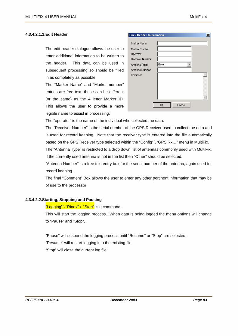
MULTIFIX 4 USER MANUAL MultiFix 4
4.3.4.2.1.1
e header. This data can be used in
ocessing so should be filled
.
the 4 letter Marker ID.
his allows the user to provide a more
assist in processing.
f the individual who collected the data.
xt entry box for the serial number of the antenna, again used for
cord keeping.
4.3.4.2.2.Starting, Stopping and Pausing
.Edit Header
The edit header dialogue allows the user to
enter additional information to be written to
th
subsequent pr
in as completely as possible
The “Marker Name” and “Marker number”
entries are free text, these can be different
(or the same) as
T
legible name to
The “operator” is the name o
The “Receiver Number” is the serial number of the GPS Receiver used to collect the data and
is used for record keeping. Note that the receiver type is entered into the file automatically
based on the GPS Receiver type selected within the “Config” \ “GPS Rx…” menu in MultiFix.
The “Antenna Type” is restricted to a drop down list of antennas commonly used with MultiFix.
If the currently used antenna is not in the list then “Other” should be selected.
“Antenna Number” is a free te
re
The final “Comment” Box allows the user to enter any other pertinent information that may be
of use to the processor.
“Logging” \ “Rinex” \ “Start” is a command.
This will start the logging process. When data is being logged the menu options will change
to “Pause” and “Stop”.
“Pause” will suspend the logging process until “Resume” or “Stop” are selected.
“Resume” will restart logging into the existing file.
“Stop” will close the current log file.
REFJ500A - Issue 4 December 2003 Page 83

MULTIFIX 4 USER MANUAL MultiFix 4
4.3.5. ACTION
Setup001 - MultiFix 4 MultiFix 3
Configure TSIP Configure Ashtech
SV Status
File Config Logging Action View Options Tools Window Help
DefaultAdvanced
Restart Sockets Collect Almanac
Setup001 - Fix File Config Logging Action View Options Tools Window Help
Reset SkyFix XP Filter
Configure MillenniumConfigure OEM4
Update SkyFix
he Action menu item “Configure TSIP” will only appear if the GPS receiver selected uses the
Trimble), BD112 (Trimble) or SK8 (Trimble).
Ashtech” option will only be displayed if an Ashtech receiver is selected, i.e. Z
amily, DG16, G12 or GG24.
nnium” and “Configure OEM4” options will only be
4 receiver is selected.
4.3.5.1. Restart Sockets
T
TSIP communication protocol, i.e. DSM (
The “Configure
F
In the same way the “Configure Mille
displayed if a NovAtel Millennium or OEM
“Action” \ “Restart Sockets”
On occasion heavy network traffic may lock
reinitialise all currently open sockets witho
configura
up any or all TCP\IP socket ports. This option will
ut having to restart the software or editing the
tion files.
4.3.5.2. Co
llect Almanac
“Action” \ “Collect Almanac”
ultiFix 4 will not work without almanac data. When the program is first opened there is an
utomatic series of requests for almanac data to the GPS receiver. If the receiver is not
data. Once communications
hed a request for almanac data can be forced using this
cility. Current almanac information is displayed under “View” \ “GPS” \ “Almanac” (see
ection.4.3.6.4.7 page 106).
ire all the information as it is updated at 1 SV per minute.
M
a
available to the program at that time there will be no almanac
with the receiver have been establis
fa
s
Without a forced almanac update, almanac information would still be acquired albeit slowly. It
can take up to 30 minutes to acqu
REFJ500A - Issue 4 December 2003 Page 84

MULTIFIX 4 USER MANUAL MultiFix 4
4.3.5.3. Update SkyFix
“Action” \ ”Update SkyFix”
This function allows the user to update the SkyFix beams and station lists within MultiFix by
XML file with the extension *.sfx without having to wait for a new software
made to the SkyFix network a new XML file will be made
vailable to MultiFix users allowing them to update their software.
[Update SkyFix] option will call up a
control menu.
ork] will default the
[Ok] will close the “Input
[Ok] to accept the
being used in the
ill be affected.
means of an
release. When changes are
a
[Set Default Netw
SkyFix network information to the
original set-up on the installation CD.
[Browse] will open the dialogue opposite.
Select the new SkyFix Network file, this
will have the extension *.sfx and click
[Open]
Clicking on
SkyFix File” dialogue.
MultiFix will then display a “Warning”, click
changes or [Cancel] to reject them.
NB changes made to stations or beams that are currently
configuration w
REFJ500A - Issue 4 December 2003 Page 85

MULTIFIX 4 USER MANUAL MultiFix 4 MULTIFIX 4 USER MANUAL MultiFix 4
REFJ500A - Issue 4 December 2003 Page 86
set SkyFix-XP Filter 4.3.5.4. Re
“Action” \ ”Reset SkyFix-X
This function empties all
calculation. A warning win
function.
Be aware that if the fi
P Filter”
values from the Kalman Filter used in the SkyFix-XP position
dow will appear asking for confirmation prior to performing the
lter is reset then the XP solution will need to re-converge before it can
e used.
4.3.5.5. Configure TSIP
b
“Action” \ “Configure TSIP…”
This facility instructs a Trimble Standard Interface Protocol (TSIP) GPS receiver to output the
uires. This will need to be done each time power to the receiver is
D112 or DSM fitted there is battery back up on the receiver when
.
en a TSIP controlled GPS receiver is selected.
4.3.5.5.1.D n
information MultiFix 4 req
cycled. (If a 90938 has a B
the 90938 is switched off)
This display is only visible wh
efault TSIP Configuratio
“Action” \ “Configure TSIP
Accessing this dialogu
causes
…” \ “Default”
e
the program to
immediately send two
configuration messages, a
Synchronise Measurements message and an I/O Options message. As soon a response
from the receiver is received the dialogue above will be shown. If there is no link between the
computer and the receiver the dialogue will state “awaiting acknowledgement”, “unable to set
default parameters” or “waiting to reset default receiver configuration”. Every 5 seconds it will
retry to configure the receiver until [Exit] is clicked.
REFJ500A - Issue 4 December 2003 Page 86

MULTIFIX 4 USER MANUAL MultiFix 4
4.3.5.5.2.Advanced TSIP Configuration
“Action” \ “Configure TSIP…” \ “Advanced”
As with the default
ill try to establish
th the
he program provides a warning which
[OK]
“Velocity”, “Timing”
“Auxiliary” and “Synch. Mess.” Tables.
or a full explanation of
eference document,
Rev B dated Feb
999.
configuration, as soon
as this dialogue is
accessed the program
w
communication with
the receiver and try to
configure it wi
default configuration.
To change the configuration, click the [Edit] button.
T
must be read carefully. Clicking
activates the Edit Controls in the
“Position”,
F
the options available
the reader is directed to
the Trimble TSIP
R
Trimble Part No 34462-
00. The latest revision
that is held by the TSG
is
1
REFJ500A - Issue 4 December 2003 Page 87

MULTIFIX 4 USER MANUAL MultiFix 4
4.3.5.6. Configure GPS Receiver
“Action” \ “Configure Ashtech”, “Configure Millennium”, “Configure OEM4”
an Ashtech or a NovAtel GPS receiver has been selected for use
l communications have already been established
n Ashtech or NovAtel GPS Receiver can be configured from
4.2.4.3 NovAtel for
etails on how to a establish communication link with the GPS Receiver.
4.3.5.6.1.D
Clicking on the [Set Default Config] button will send the basic set of commands needed to
configure the selected unit for use with MultiFix.
4.3.5.6.2.Advanced Receiver configuration
The [Advanced Config] Button will call up a
control menu.
[Refresh Settings] will update the display.
[Request Receiver Details] will interrogate
the GPS receiver settings and send
commands to the unit.
[Save Receiver Configuration] will save the
current setting to the battery powered RAM
on the receiver circuit board.
The “Send Command” dialogue allows the user to send additional commands to the GPS
receiver. Please refer to the appropriate Ashtech or NovAtel handbooks for details of the
available commands.
If
with MultiFix then the ”Configure Ashtech”, ”Configure Millennium”
or ”Configure OEM4” dialogue will be made available.
Assuming seria
a
within MultiFix.
See section 4.2.4.1 Ashtech (Thales Navigation) Receivers or section
d
efault Receiver configuration
REFJ500A - Issue 4 December 2003 Page 88
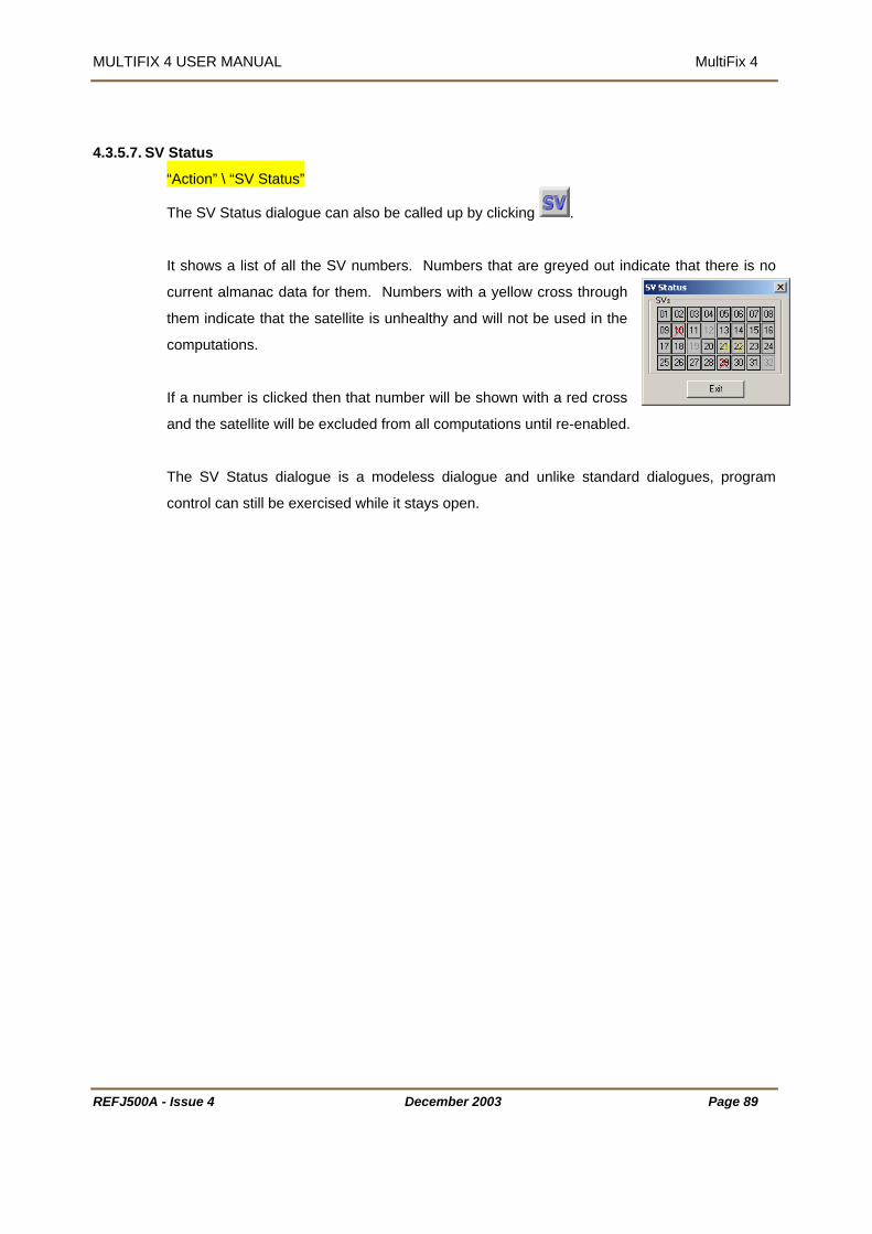
MULTIFIX 4 USER MANUAL MultiFix 4
s 4.3.5.7. SV Statu
“Action” \ “SV Status”
The SV Status dialogue can also be called up by clicking .
It shows a list of all the SV numbers. Numbers that are greyed out indicate that there is no
current almanac data for them. Numbers with a yellow cross through
them indicate that the satellite is unhealthy and will not be used in the
computations.
If a number is clicked then that number will be shown with a red cross
and the satellite will be excluded from all computations until re-enabled.
The SV Status dialogue is a modeless dialogue and unlike standard dialogues, program
control can still be exercised while it stays open.
REFJ500A - Issue 4 December 2003 Page 89

MULTIFIX 4 USER MANUAL MultiFix 4
4.3.6. VI
EW
The items show in brown will only appear if pre-conditions have been met.
“Files” will only appear in replay mode.
“Datagrams” only appears if a UDP socket has been defined.
“Receiver” only appears if a 4000 Series (Trimble), MS750 (Trimble) or BD750 (Trimble) is
the selected GPS receiver type.
“Iono Filter” will only appear if one of the computations is designated as “Premier”.
“SkyFix Decoder” only appears if it has been selected that one or more RTCM source(s) is a
Fugro decoder and it is outputting test data.
Right-mouse clicking most windows allows the user to customise the display. Where that
will be mentioned in the relevant section in the
manual. Several windows share the same two
the clipboard from where it can be pasted into
customisation is specific to the view window it
facilities of “Copy” and to “Save As…”.
“Copy” places a bitmap of the window onto
another application.
“Save As…” allows an html or bitmap file of the view window to be saved. By default the files
will be placed in the folder that contains the MultiFix configuration file. The bitmap files are
REFJ500A - Issue 4 December 2003 Page 90

MULTIFIX 4 USER MANUAL MultiFix 4
saved as *.bmp images but the html file does not contain images but instead has links to the
ges, so when MultiFix saves an html file the bitmaps are saved as well. When an html file
o HTML Association file is also created. If the html file is deleted the
utside the area displayed by the monitor. The application workspace automatically extends
and scroll bars are provided. The scroll bars allow the display area to move around the
extended application workspace. There is no limit on the number of windows of any type that
can be open in the application workspace. Multiple copies of the same window type can be
open. Indeed it will be seen that once a window is open some types of window allow further
selection of the data that is to appear in them.
ima
is saved a Zer
associated bit maps are deleted as well
In common with many Windows programs, MultiFix allows display windows to be moved
o
Display Area
Extended Application Workspace Horizontal Scroll Bar Vertical Scroll Bar
Setup001 - MultiFix 3
File Config Logging Action View Options Tools Window Help
Multi Fix 3
Loading 12% Response 5% 1:03:25 pm UTC
Display Area
Extended Application Workspace Horizontal Scroll Bar Vertical Scroll Bar
Setup001 - MultiFix 4
File Config Logging Action View Options Tools Window Help
Loading 12% Response 5% 1:03:25 pm UTC
t n Workspace
Most windows can be resized by clicking and dragging the corners or sides. Some windows
that contain text will wrap the text message into the available space. Other windows
containing text will simply be cropped as the window size reduces. Windows containing
graphical information will resize down to a minimum and will then either crop the information
or will introduce scroll bars.
Figure 5 Windows Extending Beyond the Applica io
REFJ500A - Issue 4 December 2003 Page 91

MULTIFIX 4 USER MANUAL MultiFix 4
4.3.6.1. Files
“View” \ “Files”
In replay mode the progress of the playback can be followed in the “Files” view window. The
pper bar shows the status of the replay in percentage of the total time, while the lower part of
the window shows the selected files as green blocks and the progress within the current file.
u
rk Area 4.3.6.2. Wo
“View” \ “Work Area”
compass the user’s current position and the
he right hand side of the
on the users current
cation.
ia the right mouse button click.
This calls up a diagrammatic map, which will en
positions of all reference stations
currently selected, and available,
in the RTCM input data.
T
window contains the ranges to
each of the selected stations,
based
lo
This window has a “Copy” and
“Save As…” facility, accessed
v
The work area can also be called up by clicking
REFJ500A - Issue 4 December 2003 Page 92

MULTIFIX 4 USER MANUAL MultiFix 4
4.3.6.3. Input / Output
“View” \ “IO”
nus and each will call a window to the MultiFix 4 application There are three sub-me
workspace.
4.3.6.3.1.Status
“View” \ “IO” \ “Status”
This window indicates when there is port
the window will contain the ports
The “None” I/O
hannel is at the top followed by streamed
socket channels, datagram sockets and then
t
A right-mouse click calls up the [Channel] button. When this is
clicked the IO Status dialogue is presented. This allows
channels to be selected or deselected from the status window.
In the IO Status window the latest time is in the centre between
the Input and Output columns. Each box indicates when data
has been input or output, over the last 5 seconds, on that port
by scrolling vertical bars from the centre to the outside edges of the window. The box re-
scales such that the greatest data rate over the last 5 seconds is full scale. The current bit
rate is shown opposite the I/O channel name.
activity.
By default
MultiFix knows to exist.
C
the COM and Digiboard channels.
(When setting up Input / Output channels there is the option to select a dummy channel
“None”. If selected the blue vertical bars would be seen progressing across the None Outpu
box.)
REFJ500A - Issue 4 December 2003 Page 93

MULTIFIX 4 USER MANUAL MultiFix 4
4.3.6.3.2.Sockets
“View” \ “IO” \ “Sockets””
le and Connecting will alternate while connection
tdown to the next attempt to make
contact.
A server socket can have two states,
le and Listening.
4.3.6.3.3.D
A client socket can have three states,
Idle, Connecting and Connected.
Id
is trying to be established. There will also be a
time coun
Id
The Idle status is almost immediately replaced by Listening.
atagrams
“View” \ “IO” \ “Datagrams”
The Datagram Status window lists all Datagrams in use. The IP address indicates to which
“Packets In” and
e receiving data only the
ets In” will increase at n
PC a link is in place or if it is transmitting a broadcast message. The
“Packets Out” window indicates if the datagram is working. If you ar
“Packets In” will increase. If you are transmitting to n PCs the “Pack
times the rate of the “Packets Out”.
REFJ500A - Issue 4 December 2003 Page 94
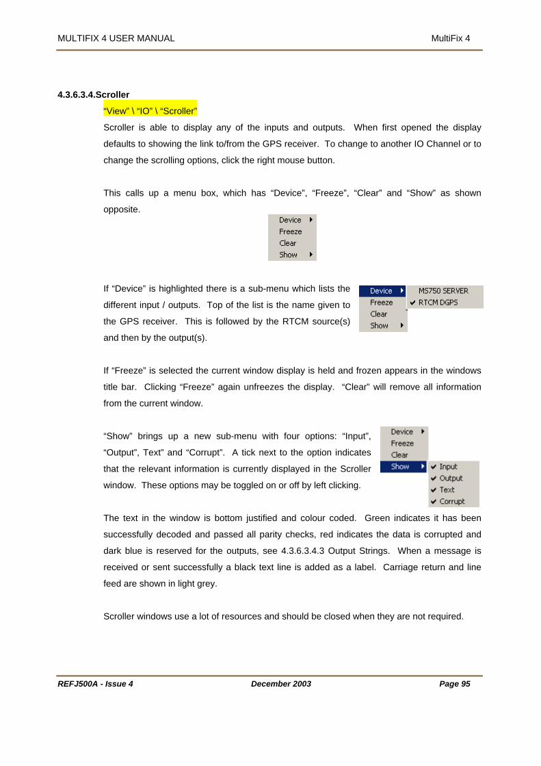
MULTIFIX 4 USER MANUAL MultiFix 4
4.3.6.3.4.Scroller
“View” \ “IO” \ “Scroller”
Scroller is able to display any of the inputs and outputs. When first opened the display
defaults to showing the link to/from the GPS receiver. To change to another IO Channel or to
change the scrolling options, click the right mouse button.
This calls up a menu box, which has “Device”, “Freeze”, “Clear” and “Show” as shown
opposite.
If “Device” is highlighted there is a sub-menu which lists the
utputs. Top of the list is the name given to
the GPS receiver. This is followed by the RTCM source(s)
and then by the output(s).
If “Freeze” is selected the current window display is held and frozen appears in the windows
title bar. Clicking “Freeze” again unfreezes the display. “Clear” will remove all information
from the current window.
“Show” brings up a new sub-menu with four options: “Input”,
“Output”, Text” and “Corrupt”. A tick next to the option indicates
that the relevant information is currently displayed in the Scroller
window. These options may be toggled on or off by left clicking.
The text in the window is bottom justified and colour coded. Green indicates it has been
successfully decoded and passed all parity checks, red indicates the data is corrupted and
dark blue is reserved for the outputs, see 4.3.6.3.4.3 Output Strings. When a message is
received or sent successfully a black text line is added as a label. Carriage return and line
feed are shown in light grey.
Scroller windows use a lot of resources and should be closed when they are not required.
different input / o
REFJ500A - Issue 4 December 2003 Page 95

MULTIFIX 4 USER MANUAL MultiFix 4
4.3.6.3.4.1.GPS Receiver
4.3.6.3.4.2.RTCM Input
.Output Strings 4.3.6.3.4.3
REFJ500A - Issue 4 December 2003 Page 96

MULTIFIX 4 USER MANUAL MultiFix 4
4.3.6.4. GPS
“View” \ “GPS”
4.3.6.4.1.Receiver
“View” \ “GPS” \ “Receiver”
This menu item will only appear if a 4000 (Trimble), BD750 (Trimble) or an MS 750 (Trimble)
GPS receiver has been defined. This window cannot be resized.
Assuming communication has been achieved between the receiver and the MultiFix program,
the “Yellow Box” window acts as a remote interface with the GPS receiver in use. Clicking a
button in the window performs that action on the receiver. Likewise if the menu on the
receiver is being used the “Yellow Box” receiver window in MultiFix will update to the currently
displayed page.
The UTC time displayed in the “Yellow Box” window will always be 1 or 2 seconds behind the
UTC time shown in the Clock window. This is not a cause for concern as it is due to the time
taken for the receiver to provide the front panel text.
Beware: Do not change the settings of the port communicating with the MultiFix 4 program.
Once communication is lost it cannot be re-established from MultiFix 4 and must be done via
the receiver.
REFJ500A - Issue 4 December 2003 Page 97

MULTIFIX 4 USER MANUAL MultiFix 4
4.3.6.4.2.Measurements
“View” \ “GPS” \ “SNR”
ximum over the last 60
pdates. The button position shows the current value. The button will be Red when there are
filter, Yellow when between 30 and 59 and Green when 60 values have
The display shows the signal to noise (SNR) levels of each of the tracked satellites as a
button on a bar. The width of each bar shows the minimum and ma
u
<30 values in the
been obtained.
If two Measurement windows are opened they will not sho
second Measurement window has received 60 updates.
The signal
w the same information until the
level may vary widely if the satellite is just rising, setting, or if high levels of
ultipath are present.
he Y-axis will re-scale as rising satellites are acquired and setting satellites are lost.
is data from the GPS receiver will still appear in the window even if
they are disabled in “Action” \ “SV Status”.
m
The X-axis re-scales as a function of the least minimum and the greatest maximum to be
displayed.
T
Satellites for which there
REFJ500A - Issue 4 December 2003 Page 98

MULTIFIX 4 USER MANUAL MultiFix 4
If using a dual frequency receiver then SNR’s will be shown for L1 and L2 when in Premier or
P mode.
he “EL” column shows the elevation angles of the tracked satellites. By right clicking and
selecting the
X
T
option satellites can be sorted by elevation angle.
Unselecting this option will rearrange SNR’s in ascending PRN order.
4.3.6.4.3.Scintillation Meter
“View” \ “GPS” \ “Scintillation meter”
The “Scintillation Meter” window provides a visual display of how the scintillation filter is
working.
For an explanation of scintillation see APPENDIX B – Understanding Scintillation.
he display contains four bars for each satellite currently being tracked.
d
terruption. The full length of this bar equates to 60
hold for the maximum number of
cceptable breaks during the past 60 seconds. This is
set to two.
When data is acceptable the display remains green.
When the scintillation filter rejects data the display will turn red. If no data is currently
available then the display will turn grey.
Please note that if data is rejected on L2 only data will remain available on L1 for single
frequency calculations.
T
The four bars are subdivided into two representing each frequency. The upper pair shows
tracking on L1 and the lower pair shows L2.
The upper of each pair of bars represents the number of
interruptions detected during the past 60 seconds. If
there are no interruptions the bar remains empty.
The lower bar indicates the time since the last detecte
in
seconds. The vertical black line across the whole display
indicates the thres
a
REFJ500A - Issue 4 December 2003 Page 99

MULTIFIX 4 USER MANUAL MultiFix 4
4.3.6.4.4.Code Carrier Filter (CCF)
“View” \ “GPS” \ “CCF”
F
S.D. ofCode
R
igure 6 Graphical Representation of the Code Carrier Filter
t the heart of the DGPS and Premier calculations is the Code Carrier Filter. This filter
gular short-term cyclical
attern whereas noise is considered to be random, therefore for each epoch the program
estimates what effect Multipath is having on the measurements from each satellite. It then
derives measurement values with the estimated Multipath removed.
The heart of SkyFix-XP calculations is a Kalman Filter.
The Code Carrier Filter performance is displayed in the following two windows, “Summary”
nd “Time Series”.
A
attempts to model and remove Multipath. Strong Multipath has a re
p
a
Time Now
Raw Value at Each EpochMultipath Estimate at Each EpochCode Carrier Filter values at each Epoch(having removed Multipath)
Averaging Time
RawMean
S.D. of theRawMean
CarrierFilter
CodeCarrierMean
EFJ500A - Issue 4 December 2003 Page 100

MULTIFIX 4 USER MANUAL MultiFix 4 MULTIFIX 4 USER MANUAL MultiFix 4
REFJ500A - Issue 4 December 2003 Page 101
4.3.6.4.4.1.Summary
“View” \ “GPS” \ “CCF” \ “Summary”
The code carrier filter displays are
n by checking or un-checking the relevant name.
arguably the most significant displays for
monitoring GPS measurement quality.
The right-mouse button provides display
options for the window.
Any of the four bar chart information
panels can be turned off or o
The averaging time used for the display can be set to 1 minute, 2 minutes or 5 minutes. (This
oes not change the Time Constant of the Filter itself). The averaging time is a moving d
window, losing the oldest adding the newest.
The layout can be set to Square (as shown above), Column or Row.
REFJ500A - Issue 4 December 2003 Page 101

MULTIFIX 4 USER MANUAL MultiFix 4
The yellow bars represent the standard deviation of the code carrier filters values and the
deviation of the raw code carrier values.
on of the range of values to be displayed. Take particular
are in metres.
MultiPath” shows the results of the program’s modelling of the Multipath. Each Multipath
ultipath estimate. The hatched area shows the minimum,
h over the averaging time being used for the display. If the
g satisfactorily the buttons should oscillate either side of 0 in a random manner.
the values persist in fluctuating more than 2-5 metres, or some of the current values stay
igh, it may indicate the antenna is sited in an area prone to Multipath and removal to another
cation may be advisable.
Performance” shows the Standard Deviation of the Code Carrier Filter values and the
between the mean of the Filtered Code Carrier values and the
y the mean of the filtered
es and therefore should be 0. A large
ifference indicates the filter is not modelling the raw data successfully.
Innovation shows the Standard Deviation of the Innovation. Innovation is the difference
between the Code Carrier Filter’s predicted value and the Code Carrier Filter’s raw value
(corrected for Multipath). If the filter is performing successfully the raw values should be
randomly distributed around the filtered prediction. The movement should be due to receiver
easurement noise and is an indication of the quality of the GPS measurements.
green bars represent the standard
All the panels re-scale as a functi
note of the axis labels. All units
“
panel button shows the current M
maximum range of the Multipat
filter is workin
If
h
lo
“
Standard Deviation of the Raw Code Carrier values.
“Bias” shows the difference
mean of the Raw Code Carrier values. If the filter is working perfectl
values should be the same as the mean of the raw valu
d
m
REFJ500A - Issue 4 December 2003 Page 102

MULTIFIX 4 USER MANUAL MultiFix 4
4.3.6.4.4.2.Time Series
“View” \ “GPS” \ “CCF” \ “Time Series”
This is a time series
representation of the code
carrier filter for each
over the last 5
measurement
minutes.
The right-mouse button
provides display options for
the window.
“Raw”- shows red dots representing the raw observations
“Filter” - shows a smoothed green line indicating the observations after the Multipath
estimate has been removed
“Multipath” - shows an erratic yellow line is the Multipath estimate.
“Natural” - a smooth blue line is going to be removed.
REFJ500A - Issue 4 December 2003 Page 103

MULTIFIX 4 USER MANUAL MultiFix 4
If dual frequency data is
being received two sets of
graphs will be displayed,
showing the code carrier
filter information of both the
L1 and L2 frequencies.
.3.6.4.4.3.SNR Weight
4
“View” \ “GPS” \ “CCF” \ “SNR Weight”
th regard to the signal to noise ratio weightings of the
measuremen rally, a lower SNR value is indicative of more noise and Multipath in an
more weight within the computation process to a
e.
This screen provides information wi
ts. Gene
observation. MultiFix 4 will give
measurement with a higher SNR valu
The first column shows the SNR value of the measurement.
The second shows the number of observations with that SNR value.
The third is the minimum measurement.
The fourth column is the mean.
The fifth column is the standard deviation of the observations.
The sixth column shows the maximum value.
The final column shows the relative weight of the measurements with respect to the best
of 1.00. If there are less than 600 observations for an SNR value, which is assigned a value
REFJ500A - Issue 4 December 2003 Page 104
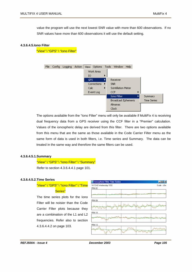
MULTIFIX 4 USER MANUAL MultiFix 4
REFJ500A - Issue 4 December 2003 Page 105
value the program will use the next lowest SNR value with more than 600 observations. If no
SNR values have more than 600 observations it will use the default setting.
4.3.6.4.5.Iono Filter
“View” \ “GPS” \ “Iono Filter”
The options available from the “Iono Filter” menu will only be available if MultiFix 4 is receiving
dual frequency data from a GPS receiver using the CCF filter in a “Premier” calculation.
Values of the ionospheric delay are derived from this filter. There are two options available
from this menu that are the same as those available in the Code Carrier Filter menu as the
same form of data is used in both filters, i.e. Time series and Summary. The data can be
treated in the same way and therefore the same filters can be used.
4.3.6.4.5.1.Summary
“View” \ “GPS” \ “Iono Filter” \ “Summary”
Refer to section 4.3.6.4.4.1 page 101.
4.3.6.4.5.2.Time Series
“View” \ “GPS” \ “Iono Filter” \ “Time
Series”
The time series plots for the Iono
Filter will be noisier than the Code
Carrier Filter plots because they
are a combination of the L1 and L2
frequencies. Refer also to section
4.3.6.4.4.2 on page 103.

MULTIFIX 4 USER MANUAL MultiFix 4
REFJ500A - Issue 4 December 2003 Page 106
4.3.6.4.6.Ephemeris
“View” \ “GPS” \ “Broadcast Ephemeris”
The Ephemeris window shows the previous 6-hour period. The Ephemeris issue number is
placed at the time when an update was received. The issue number typically increments by 1
but that is not always the case. The
majority of updates occur every 2
hours. Updates between this period
may be due to a rising SV.
A right-mouse click on the window
provides the “Copy” and “Save As…” facilities.
4.3.6.4.7.Almanac
“View” \ “GPS” \ “Almanac”
A right-mouse click on the window provides the “Copy” and “Save As…” facilities as various
other options.
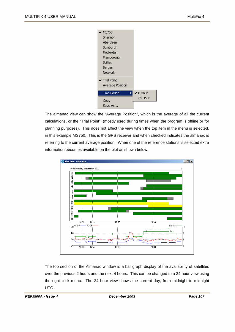
MULTIFIX 4 USER MANUAL MultiFix 4
The almanac view can show the “Average Position”, which is the average of all the current
calculations, or the “Trial Point”, (mostly used during times when the program is offline or for
ted,
this example MS750. This is the GPS receiver and when checked indicates the almanac is
referring to the current average position. When one of the reference stations is selected extra
information becomes available on the plot as shown below.
planning purposes). This does not affect the view when the top item in the menu is selec
in
The top section of the Almanac window is a bar graph display of the availability of satellites
over the previous 2 hours and the next 4 hours. This can be changed to a 24 hour view using
the right click menu. The 24 hour view shows the current day, from midnight to midnight
UTC.
REFJ500A - Issue 4 December 2003 Page 107

MULTIFIX 4 USER MANUAL MultiFix 4
REFJ500A - Issue 4 December 2003 Page 108
The green bars represent healthy satellites above the elevation mask.
If an SV is disabled in the “Action” \ “SV Status” dialogue than the bar for that SV will
appear red.
The grey areas indicate the SV is above the 10° elevation mask at the reference
station but not at the “average position” or the “trial point”. (Note that the minimum
elevation mask is set in the “Config” \ “Calc” \ “Settings” dialogue, (see Section
4.3.3.4.1 on Page 63). By default this is 10º but can be changed resulting in the SV
availability shown in the Almanac window altering.)
The yellow bars represent unhealthy SV’s.
The lower section shows the Number of SV’s, PDOP and HDOP on a line graph over the time
period specified.
The number of satellites available for the selected position calculation is shown as a
solid green line.
The number of satellites visible at both the reference station(s) and the selected
position is a green dashed line (where applicable).
PDOP at the selected position as a red dashed line.
PDOP based on the common satellites above the masks as a red solid line
HDOP at the selected position is shown as a blue dashed line
HDOP based on the common satellites above the masks as a blue solid line
If “Network” is selected the Almanac window is based on the current “average position” or the
“trial point” and will show a green availability bar if there is at least one of the reference
stations that has a common satellite. If the bar is grey then the satellite is available at the
“Average” position or “Trial Point” position but not at any of the reference stations.
It is worth noting that MultiFix 4 uses “Elevation Delta” for rising and setting satellites.
“Elevation Delta” is a variable weighting of the satellite data in the position solution. The
minimum elevation when a satellite starts to be used and the number of degrees above the
minimum at which the satellite attains full weighting are set in the “Config” \ “Calc” \ “Settings”
dialogue referred to above.

MULTIFIX 4 USER MANUAL MultiFix 4
4.3.6.4.8.Clock
“View” \ “GPS” \ “Clock”
As can be seen, GPS Time was 13 seconds ahead of UTC Time when this screen dump was
taken.
It is possible to include extra clocks in this display by right clicking in the window and selecting
“Add Local…”.
Enter a name for the clock and the time offset, in the format (hh:mm:ss), then click [OK].
These can be used to provide a local time offset from UTC for the work area.
Right clicking on the window now provides extra options to “Edit”, “Delete”, or “Hide” the
additional clock(s).
REFJ500A - Issue 4 December 2003 Page 109

MULTIFIX 4 USER MANUAL MultiFix 4
rrections 4.3.6.5. Co
“View” \ “Corrections”
4.3.6.5.1.Orbit Data
“View” \ “Corrections” \ “Orbit Data”
This menu is available when SkyFix-XP Mode is selected in “Config” \ “Calc” \ “Settings…”
4.3.6.5.1.1.Time Series
“View” \ “Corrections” \ “Orbit Data” \ Time Series”
This shows the received position and clock offsets for the selected satellites in four
dimensions.
REFJ500A - Issue 4 December 2003 Page 110

MULTIFIX 4 USER MANUAL MultiFix 4
The red line is X, green is Y, blue is Z, and grey is Time.
To show the plot for a specific satellite, click the corresponding number on the number pad on
the right hand side of the window. If more than one number is selected then the relevant
graphs are added below the initial one.
Coloured crosses on the number pad indicate the status of the satellites as described below:
Yellow – The satellite is unhealthy. No plot is available.
Light Blue (Aqua) – The satellite data is missing
Red – The satellite had been disabled by the user via the “Action” \ “SV Status” dialogue.
The pink vertical line in the example above represents an IODE change with the values
shifting after this event reflecting the new information received.
4.3.6.5.1.2
.Data Table
“View” \ “Corrections” \ “Orbit Data” \ Data Table”
The upper table of the “Orbit Correction Data” window shows:
REFJ500A - Issue 4 December 2003 Page 111

MULTIFIX 4 USER MANUAL MultiFix 4
“Current Source” – indicates whether System 0 or System 1 at the NCC is supplying the
Latency” – Total elapsed time from the time of reference station measurement to when the
correction (Calculation Time + Communication Delay).
corrections received.
d.
Data Ephemeris followed by a single bit IODE change flag
his toggles between 0 and 1 upon receipt of IODE).
ge give the position correction of the satellite in the three axes of
current orbit rate corrections (orbit rate
satellite during the period between its
bsolute orbit corrections).
current SkyFix-XP corrections.
“
user applies the
“Station ID” - which is the Beam ID for the SkyFix-XP
“Last Update” - which is the GPS time of the last message receive
The lower table shows:
“PRN” - satellite number,
“IODE” - which is the Issue Of
(T
“Age” - which is the elapsed time from the time corrections were last updated for a PRN.
“dX”, “dY”, and “dZ” - which are the current absolute orbit corrections, (the three absolute
corrections per messa
Euclidean space, relative to the broadcast ephemeris)
“dX dot”, “dY dot”, and “dZ dot” - which are the
corrections are used to predict the position of a given
a
“Clk” - which is the current clock correction (metre-level + sub-metre level corrections).
4.3.6.5.2.DGPS Data
“View” \ “Corrections” \ “DGPS Data”
REFJ500A - Issue 4 December 2003 Page 112

MULTIFIX 4 USER MANUAL MultiFix 4
REFJ500A - Issue 4 December 2003 Page 113
4.3.6.5.2.1.Station
“View” \ “Corrections” \ “DGPS Data” \ “Station”
The window initially opens showing the first RTCM reference station. To have the window
show data for another station, right click on the window and select the station.
The top left table shows the time tag of the latest messages, the age of the corrections and
the percentage.
For Type 1 messages a percentage of 30 seconds.
For Type 2 messages a percentage of 300 seconds.
For Iono (Type 55 or Type 15) messages a percentage of 600 seconds.
Message (Type 16) a percentage of 600 seconds. When received the message will be
displayed at the top of the window and will remain for 10 minutes unless overwritten.
The Location shows the station position as received in the Type 3 message.
The lower table has various sub-sections.
“PRN” is the satellite number.
“Position” shows the satellites’ positions and if they are rising the elevation is tagged with a ^.
“Atmosphere” has: -
“Direct” is the ionospheric delay derived for the present moment from the dual frequency
information. (It will not be present if a single frequency reference station is selected).

MULTIFIX 4 USER MANUAL MultiFix 4
“Iono” is the ionospheric delay for time now from the Klobachar model
opospheric delay for time now from the tropospheric model.
ype 1” has: -
”, which is the User Differential Range Error, (normally 0)
“SF” is flagged when the Correction Rate is g
±660.
rent Issue of Ephemeris to the reference
tation being viewed.
“Corrn”, which is the correction to the correction based on the difference in IODE.
“Rate”, which is the rate of change of the correction.
“IODE”, which is the Issue of Data Ephemeris number.
irect” contains the Ionospheric delay values and rates as transmitted in the Type 15 or 55
4.3.6.5.2.2.Performance
Tropo is the tr
“T
“Corrn.”, which is the current pseudo-range correction
“Rate”, which is the rate of change of the pseudo-range correction
“IODE”, which is the Issue of Data Ephemeris
“U
reater then ±0.256 or when the correction is
>
The “Type 2” table will usually only be seen during an Ephemeris change (every 2 hours),
when the mobile’s GPS receiver is using a diffe
s
“D
messages. (Without Type 15/55 information the section will be omitted).
“View” \ “Corrections” \ “DGPS Data” \ “Performance”
his window refers to a particular reference station.
hen first opened it defaults to the first reference
station in the list. To change to another station use
a right-mouse click and select a different station in
the “Station” dropdown list.
.
The RTCM Performance window has two sections.
he top is for Type 1 RTCM correction messages.
he bottom for Type 15/55 Ionospheric Delay
T
W
A right-mouse click also shows that the view
window can be copied and saved
T
T
REFJ500A - Issue 4 December 2003 Page 114

MULTIFIX 4 USER MANUAL MultiFix 4
REFJ500A - Issue 4 December 2003 Page 115
correction messages. If the reference station has not got the capability to transmit Type 15 or
55 messages then that part of the window remains blank.
The “Availability” bar at the top refers to the current day, midnight to midnight.
A grey area indicates a period when the program was not running.
A red area indicates when there had been no corrections received from the station for
more than 50 seconds.
A white area indicates either corrections were present or that time of day has not yet
been reached.
The “Latency” histogram shows how old the corrections from the station were at each epoch,
so if corrections that were 2 seconds old on receipt were received regularly every 6 seconds
the histogram would show a spread from 2 to 8 seconds.
The “SV’s Tracked” histogram shows the spread in the numbers of SV’s tracked each epoch.
The “Iono Type 15/55” tables at the bottom show the same information as above for those
message types. The permitted Type 15/55 messages are not considered stale until 600
seconds has elapsed rather than the 50 seconds for the Type 1 messages.

MULTIFIX 4 USER MANUAL MultiFix 4
REFJ500A - Issue 4 December 2003 Page 116
4.3.6.5.2.3.Time Series
“View” \ “Corrections” \ “DGPS Data” \ “Time Series”
This window shows the pseudo-range differences between satellites computed positions for
all selected reference stations. By clicking the mouse button on a satellite number in the key
then the display changes to show only that satellite. The Y axis on the plot is metres.
Right clicking on this window gives various options. Selecting a station in “Differences” will
then difference all data to that station. This indicates how closely the positions for each
satellite match at the selected reference stations.
Selecting “Scale” will give the option to change the Y-Axis automatically or show it at 1, 5, 10,
20, or 30 metres.

MULTIFIX 4 USER MANUAL MultiFix 4
Selecting “Time” will rescale the X-axis to show 5, 10 or 20 mins.
Selecting “Frequency” \ “Dual” allows dual frequency data to be shown for reference stations
et up as a Premier calculation.
s
4.3.6.5.3.SkyFix Decoder
Assuming the SkyFix Decoder option has been enabled and given an IO channel, see Section
2.5 and 6 minutes.
4.3.3.3.1 on page 60, the output from the decoder can be viewed.
The decoder can output “TEST” data on port 4 only. The interval between updates occurs
every 1000 data blocks received and is proportional to the satellite channel data rate.
This update rate may be between
REFJ500A - Issue 4 December 2003 Page 117

MULTIFIX 4 USER MANUAL MultiFix 4
REFJ500A - Issue 4 December 2003 Page 118
4.3.6.5.3.1. Table
“View” \ “Corrections” \ “SkyFix Decoder”\”Table”
The table display presents the last data set received.
The BER or Bit Error Rate is typically between 5 and 7.
The Voltage is the signal strength voltage, <1 volt indicates
poor signal level and >2 volts indicates good signal level. A large difference between min
mean and max would indicate inconsistent tracking or interference.
The Frequency Offset should be in the range ±2.50 kHz.
4.3.6.5.3.2. History
“View” \ “Corrections” \ “Fugro Decoder” \ ”History”
The history display presents a time series plot for the current 24 hour period. Each point
represents a summary for the past 1000 data blocks i.e. each message received. Note that
the plot will reset at midnight UTC.
The plots displayed are as follows:
Quality - The percentage of error free messages received
Errors - There are two lines on this graph, the green relates block synchronisation
losses and the red relates to the number of encoded block errors.
Voltage - There are three lines, minimum and maximum (both red), and mean
(green)
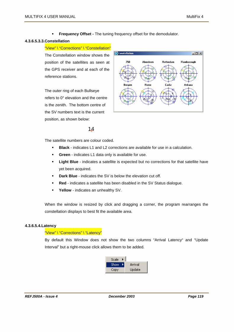
MULTIFIX 4 USER MANUAL MultiFix 4
REFJ500A - Issue 4
Frequency Offset - The tuning frequency offset for the demodulator.
4.3.6.5.3.3.Constellation
“View” \ “Corrections” \ “Constellation”
The Constellation window shows the
position of the satellites as seen at
the GPS receiver and at each of the
reference stations.
The outer ring of each Bullseye
refers to 0° elevation and the centre
is the zenith. The bottom centre of
the SV numbers text is the current
position, as shown below:
The satellite numbers
Black - indica
Green - indica
Light Blue - i
yet been acqu
Dark Blue - in
Red - indicate
Yellow - indic
When the window is
constellation displays
4.3.6.5.4.Latency
“View” \ “Corrections”
By default this Wind
Interval” but a right-mo
December 2003 Page 119
14
are colour coded.
tes L1 and L2 corrections are available for use in a calculation.
tes L1 data only is available for use.
ndicates a satellite is expected but no corrections for that satellite have
ired.
dicates the SV is below the elevation cut off.
s a satellite has been disabled in the SV Status dialogue.
ates an unhealthy SV.
resized by click and dragging a corner, the program rearranges the
to best fit the available area.
\ “Latency”
ow does not show the two columns “Arrival Latency“ and “Update
use click allows them to be added.

MULTIFIX 4 USER MANUAL MultiFix 4
The right-mouse click also allows the time scale of the Latency columns to be changed and it
he window to be copied to the clipboard. allows t
of information for each dual frequency reference station.
essages and the second row refers to Type 15 or 55
where applicable. These will only appear once messages have been received.
he Type 1 rows and Type 15/55 rows have different time scales as can be seen at the
ottom of the Latency columns.
n when the program has
e Station position message. This only has to happen
RTCM corrections from a reference
The “Latency” column shows the correction update rate as a bar. The left-hand edge of the
bar shows how old the current correction was when first received by MultiFix 4. It is a
measure of the efficiency of the correction delivery system. (The corrections are time
stamped with GPS time by the reference station, and as MultiFix 4 also has access to GPS
time the age of the corrections at the time of receipt is known). The right-hand side of the bar
advances until a new correction is received showing the age of the current correction. The
bar also shows a hatched area showing the update rate of the last correction received.
The example above has two rows
The first row refers to Type 1 m
messages
T
b
The first column after the name of the station will show a green butto
received an RTCM Type 3 Referenc
once after starting the program. The program will not use
station without a Type 3 message having been received.
REFJ500A - Issue 4 December 2003 Page 120

MULTIFIX 4 USER MANUAL MultiFix 4
REFJ500A - Issue 4 December 2003 Page 121
For Type 1 messages:
Bars will be green if the last correction was received in less than 25 seconds.
They will be yellow between 25 and 37½ Seconds.
They will be red if older than 37½ seconds. After 50 seconds the corrections from
that reference station will no longer be deemed usable.
For Type 15/55 messages:
The bars will be green if the last correction was received in less than 5 minutes.
They will be yellow if received between 5 minutes and 7½ minutes.
They will be red if older than 7½ minutes. Type 55 information is considered stale if it
is more than 10 minutes old.
The “Latency” panel has a negative area. Some GPS correction systems (not SkyFix) try to
predict corrections for a point of time in the future when a correction is to be used. If a fast
data transfer system is used the corrections can arrive with a time stamp earlier than current
time, in which case the bar will start in the negative portion of the panel.
The optional “Arrival Latency“ and “Update Interval” panels contain data extracted from the
“Latency” panel.
In “Arrival Latency” the right-hand end of the bar shows how old the current corrections were
when received by MultiFix 4.
In “Update Latency” the bar shows how long elapsed between the receipt of the current and
previous correction messages.
The “Satellites” column shows how many satellites (viable for use by MultiFix) can be seen at
each reference station.
The colour coding is: -
Green - correction data has been received for the expected satellite(s).
Yellow - the satellite(s) are unhealthy.
Dark blue – the satellite(s) is in the high scale factor mode, i.e. the resolution is
32cms as opposed to 2cms. This is usually caused by a rate value greater than
±0.256m/sec.
Light blue (Aqua) - no corrections have been received for one or more expected
satellites, i.e. it is missing.
Red - the satellite(s) has been disabled by the user in the SV Status dialogue.
In XP mode the following applies:

MULTIFIX 4 USER MANUAL MultiFix 4
REFJ500A - Issue 4 December 2003 Page 122
The whole bar indicates the total number of satellites in view at the GPS receiver.
Green – Number of satellites with valid clock correction update received.
Dark Blue - Number of satellites with no current clock correction update.
It is normal for this figure to vary as the corrections arrive in batches that include corrections
for some SV’s not currently visible. The received corrections are shown in “View” \
“Corrections” \ “Orbit Data” \ “Data Table” as black numbers in the “Clk” column (See Section
4.3.6.5.1.2).
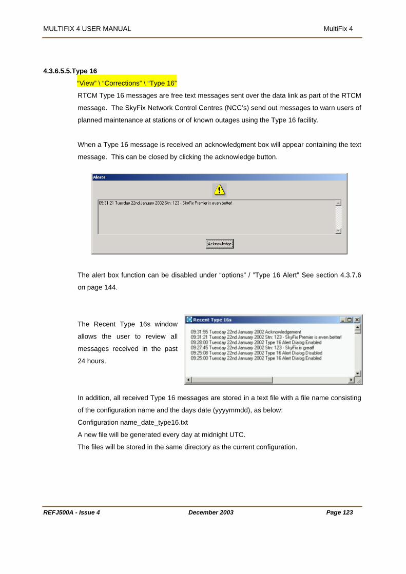
MULTIFIX 4 USER MANUAL MultiFix 4
REFJ500A - Issue 4 December 2003 Page 123
4.3.6.5.5.Type 16
“View” \ “Corrections” \ “Type 16”
RTCM Type 16 messages are free text messages sent over the data link as part of the RTCM
message. The SkyFix Network Control Centres (NCC’s) send out messages to warn users of
planned maintenance at stations or of known outages using the Type 16 facility.
When a Type 16 message is received an acknowledgment box will appear containing the text
message. This can be closed by clicking the acknowledge button.
The alert box function can be disabled under “options” / ”Type 16 Alert” See section 4.3.7.6
on page 144.
The Recent Type 16s window
allows the user to review all
messages received in the past
24 hours.
In addition, all received Type 16 messages are stored in a text file with a file name consisting
of the configuration name and the days date (yyyymmdd), as below:
Configuration name_date_type16.txt
A new file will be generated every day at midnight UTC.
The files will be stored in the same directory as the current configuration.

MULTIFIX 4 USER MANUAL MultiFix 4
REFJ500A - Issue 4 December 2003 Page 124
4.3.6.5.6.SkyFix Beams
“View” \ “Corrections” \ “SkyFix Beams”
This calls up the “SkyFix Beams Elevation and
Azimuth” display. This window includes the
elevation and azimuth to each of the currently
visible SkyFix satellites, based on the users
current location.
4.3.6.6. Calculations
“View” \ “Calc”
4.3.6.6.1.Status
“View” \ “Calc” \ “Status”
The Calculations Status window shows the status of the calculations.
In the “Calculation” section the solutions currently set up are displayed. If SkyFix-XP mode is
selected in “Config” \ “Calc” \ “Settings”, and a primary (and secondary if applicable) back-up
source has been selected, then these will appear in the top box. All other solutions will be
shown in the lower box.
In XP mode an “OP” (Output) column is also shown which displays, in the form of a green
arrow, which solution is currently being used as the XP solution. In the situation above the
“XP Calculated” position was being output. The transition between solutions is restricted to
1cm per epoch to prevent any jump in the output position, during this period the arrow is
yellow.
The “Latency” column displays the update rate of the corrections for each solution.
The “Status” section contains three columns. “Soln” indicates the status of the solution by
using an easily visible ‘traffic light’ system.
Green – The solution is good.

MULTIFIX 4 USER MANUAL MultiFix 4
REFJ500A - Issue 4 December 2003 Page 125
Yellow – The latency is too high (>25 seconds and <37.5 seconds) [If in SkyFix-XP
mode then it can also be yellow if the solution is still converging]
Red - Latency is >37.5 seconds.
The “DGPS” column states the type of solution:.
L1 Diff – Single frequency RTCM corrections received
L1/L2 Diff – Dual frequency RTCM corrections received
Standalone – No RTCM corrections received
The “Calc” column can contain the following:
OK – Position solution is good.
No Ephem – No ephemeris data received.
Too Few Meas – Enough SV’s in view but some expected measurements are
missing. (Standalone and DGPS need a minimum of 4 SV’s, XP requires a minimum
of 5).
Too Few SVs – Not enough SV’s in view.
Too Few Ephem - Enough measurements but not enough ephemeris data
No Diff - No differential corrections received for a calculation requiring corrections.
This will appear after receiving no corrections for more than 50 seconds.
Diff Too Old - Differential Corrections are more than 30 seconds old.
Too Few Diff - Not enough differential corrections to correct the calculation
Singular - Can be seen when experiencing very bad satellite constellation, i.e. all in a
narrow arc, or when reference station is geometry poor.
Divergent - The least squares solution of the position is moving more than 1
millimetre after ten iterations.
Not Required – No GPS data received.
If in SkyFix-XP mode then the following messages can also appear:
OK – Converging – XP corrections are being received and the solution is
converging.
OK – Converged – XP solution has converged below the level specified in “Config” \
“Calc” \ “SkyFix-XP…”
The “Quality Indicators” section shows various statistical values on the performance of the
corresponding solutions.
MULTIFIX 4 USER MANUAL MultiFix 4
REFJ500A - Issue 4 December 2003 Page 126
DOP - If there is no height aiding in the calculation it contains the PDOP, if height
aided then it will contain the HDOP.
SVs – The number of viable satellites
Aiding – The method of height aiding employed by the solution. “3D” indicates no
height aiding, “H+” indicates height aiding is being used
Ref Stns – The number of reference station currently used out of the ones selected.
Qual. - is the 3D a priori 50% radial error.
U. Var. - is the unit variance. If the size of calculation’s residuals are as expected the
Unit Variance will be 1.
Ext Rel. – is the largest 2D error present, possibly resulting from an undetected
outlier existing in the calculation.

MULTIFIX 4 USER MANUAL MultiFix 4
4.3.6.6.2.Positions
“View” \ “Calc” \ “Position”
Displays the result of an active computation. When
a new position window is opened it will default to
the first calculation. To select a different
is figure will be based on the entered value and not
(Type 48, 49, or 50 for SkyFix-XP) message.
on solution there may be older corrections used in
will freeze showing the status at the last
show
calculation, right click on the window to call up the
calculation list where an alternative can be selected.
Height shows the 95% confidence level. The The column beside Latitude, Longitude and
Height is with respect to the Geoid using the EGM96 model to determine the Geoid / Spheroid
separation. Note that if the user has disabled the EGM96 model and entered their own value
the “Config” \ “Calc” \ Settings…” then thin
the EGM96 Model.
“Mode” can state whether the solution is “XP”, “Differential” or “Stand Alone”.
“Latency” is the age of the most recent Type 1
If the calculation is a multiple reference stati
the solution.
“SVs” are a list of the satellites used in the calculation.
Beware that if the computation fails the window
update, it will not turn red or clear the information.
REFJ500A - Issue 4 December 2003 Page 127

MULTIFIX 4 USER MANUAL MultiFix 4
4.3.6.6.3.XP Offsets
“View” \ “Calc” \ “XP Offsets”
This option becomes available once in SkyFix-XP mode. This window is essentially the same
s the “View” \ “Calc” \ “Offsets” (See section 4.3.6.6.4) with the addition of a “Vertical” a
window showing height variations in the calculations as vertical bars. The vertical line for
each calculation indicates the 2 x Standard Deviation (95%) either side.
All other options are identical to the “View” \ “Calc” \ “Offsets” window.
REFJ500A - Issue 4 December 2003 Page 128

MULTIFIX 4 USER MANUAL MultiFix 4
4.3.6.6.4.Offsets
“View” \ “Calc” \ “Offsets”
This window shows the delta East, North and Height and the error ellipse. The error ellipse is
at the 95% confidence level.
As well as being copied and saved, the window has other options that are available by
clicking the right-mouse button.
The first concerns the Origin to which the data is referenced point. It can be the Average of
all the calculations, a static point, or any available computation.
The Average Latitude, Longitude and Height figure is not a mean but a weighted average.
The Height is with respect to the Geoid.
The Trial Point is a static point as entered under “Config” \ “Calc” \ “Settings…”. If this is
changed while a window referenced to the trial point is open the origin of the display will
move.
The data can also be referenced to any one of the available calculations.
REFJ500A - Issue 4 December 2003 Page 129

MULTIFIX 4 USER MANUAL MultiFix 4
The scale of the display can be set to be 0.2, 0.5, 1, 2, 5, 10, or 50 metres from the centre to
each edge. Alternatively it can be set to “Auto” in which case it will re-scale as required to
show all the calculated positions and the error ellipses around those positions.
distance of each computation away from the
The information below the display shows the
origin.
4.3.6.6.5.Residuals
“View” \ “Calc” \ “Residuals”
position calculation. Each source of data
is represented in a different colour.
numbers are shown on each
appropriate colour for
calculated position is
section viewed from the East.
The scale (shown under the “stations” list) changes
the LOP’s.
This screen shows the Lines Of Precision
(LOP) of the satellite ranges used in the
SV
LOP in the
each reference
station. The actual
at the intersection of the dashed lines in
the centre of each view.
The graphs represent three sections
through the calculated position.
The bottom right panel is a North Up Plan Display
The top right panel is a vertical section viewed from the South.
The bottom left panel is a vertical
automatically according to the spread of
REFJ500A - Issue 4 December 2003 Page 130

MULTIFIX 4 USER MANUAL MultiFix 4
If more than one position ) it is
possible to switch betw selecting the desired
c
Solution QC information The values are derived from statistical tests and
give an indication of how well the solution has been formed using the measurements
wer are parameters used to define different tests of reliability as
ecommended by UKOOA. The Confidence value provides a number (3 standard deviations
fr est, combined with the
P lue
may then be used to calculate the reliability of the measurement.
Unit Variance reflects th modelled values. It is
in ble performance of the
program. As such there are no set ‘Pass’ or ‘Fail’ values for unit variance. The program
takes into consideration parameters such as satellite geometry and amount of data used in
order to derive a value. A “Fail” may result from large outliers in the measurements. These
are easily identifiable from the section graphs.
RMS is the root mean square of the residuals.
The number in brackets next to the RTCM station name is the number of satellites that are
common to both the current position and the reference station.
calculation has been defined (see section 4.3.3.4.3 on page 67
een them by right-mouse clicking and then
alculation.
is also provided.
available.
Confidence and Po
r
om the mean) with which the W-Test may be performed. The W-T
ower, enables the program to calculate the Marginally Detectable error (MDE). This va
e level of error between the actual and
dependent of quality providing an indication of the reasona
REFJ500A - Issue 4 December 2003 Page 131
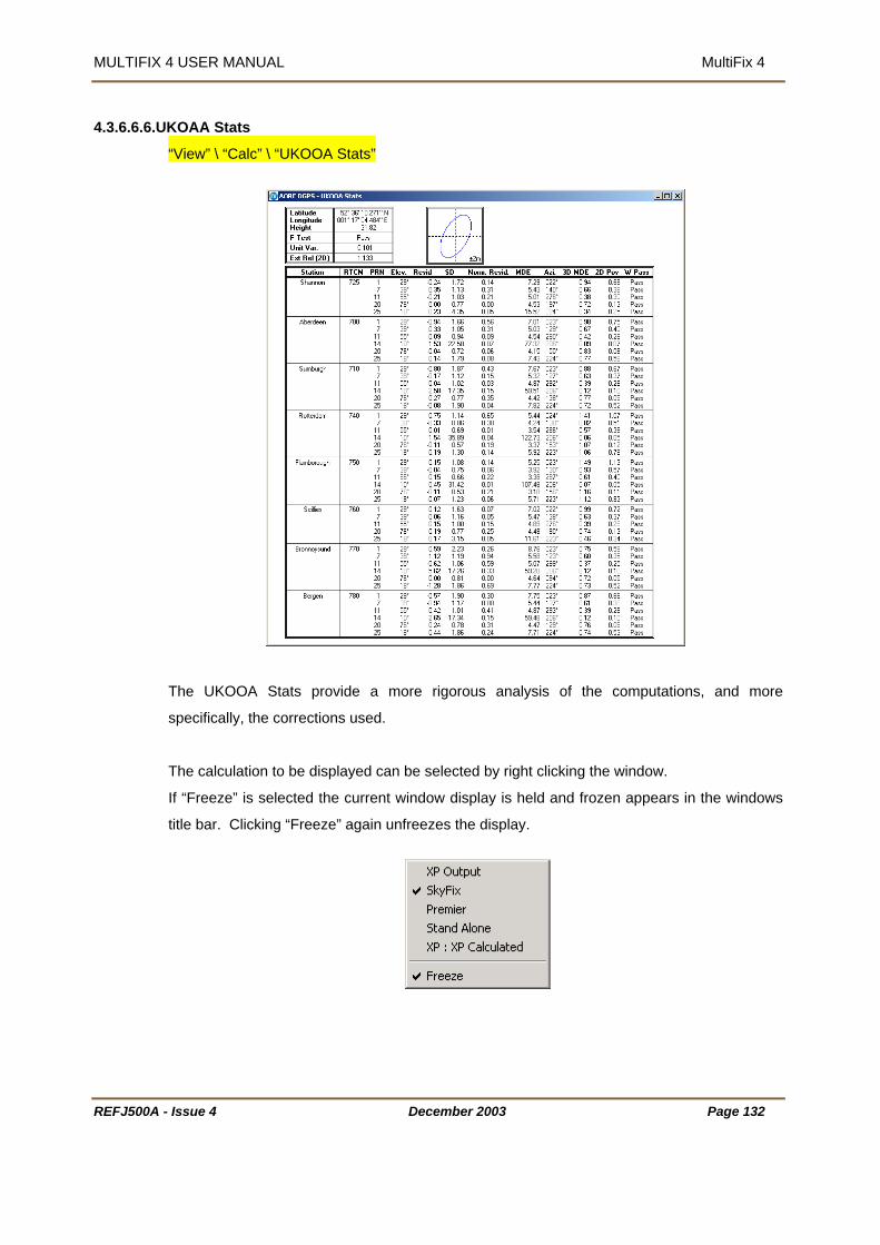
MULTIFIX 4 USER MANUAL MultiFix 4
4.3.6.6.6.UKOAA Stats
“View” \ “Calc” \ “UKOOA Stats”
The UKOOA Stats provide a more rigorous analysis of the computations, and more
specifically, the corrections used.
The calculation to be displayed can be selected by right clicking the window.
If “Freeze” is selected the current window display is held and frozen appears in the windows
title bar. Clicking “Freeze” again unfreezes the display.
REFJ500A - Issue 4 December 2003 Page 132

MULTIFIX 4 USER MANUAL MultiFix 4
REFJ500A - Issue 4 December 2003 Page 133
The display is divided into three parts.
The top left contains a summary table of the position and basic QC results.
The top centre contains a graphical plot of current error ellipse.
The bottom of the display contains the main results table including all of the UKOOA test
results.
The Summary table includes current position, F-test result, the unit variance and the
computed external reliability.
F-Test ..............................is a test applied to the unit variance. There is no fixed ‘Pass’ or ‘Fail’
values for unit variance. The program takes into consideration
parameters such as satellite geometry and amount of data used in
order to derive a value. A “Fail” may result from large outliers in the
measurements.
Unit Variance...................reflects the level of error between the actual and modelled values. It
is independent of quality providing an indication of the reasonable
performance of the calculation.
External Reliability...........External reliability is assessed by calculating the effect that an
undetected outlier (with the Magnitude of the MDE figure) will have
on horizontal position. It is considered to be a more useful concept
than internal reliability, hence its recommended use by UKOOA as
the most suitable measure of Reliability. External reliability is
measured in metres.
The Graphical Plot display contains the same error ellipse as is displayed in the “View” \
“Calc” \ “Offset” display.
The Main Table contains a number of details as listed below.
If Height Aiding is enabled the first line will be for Height. The “Residual” displayed is the
difference between the entered height and the computed height for the selected calculation.
SD for that residual is the value entered by the user under “Config” \ “Calc” \ “Settings…”
when height aiding was first set up.
The additional rows are for the corrections for each satellite from each individual station used
in the calculation.
Residual........................is the difference between the calculated range, based on the
position solution, and the observed range.
SD.................................is the standard deviation for the residual

MULTIFIX 4 USER MANUAL MultiFix 4
REFJ500A - Issue 4 December 2003 Page 134
Normalised Residual ....is the Residual divided by the standard deviation. This forms the
basis of the W-test and as such is a more accurate indicator of
whether the observation is a potential outlier.
MDE..............................is Marginally Detectable Error. This is the smallest outlier that is
likely to be detected by the current solution. This therefore is the
internal reliability.
The next four columns represent the external reliability. This is the effect that each potential
undetected outlier, as defined by the MDE, may have on the position solution. The three
columns represent:
Azimuth.........................is the orientation of any potential error in 2D
3D MDE ........................is the effect of the potential error with the size of an MDE on the
calculation in 3D
2D Pos ..........................is the effect of the potential error with the size of an MDE on the
calculation in 2D, i.e. the horizontal plane.
W Pass .........................is a pass-fail status window for the W-Test

MULTIFIX 4 USER MANUAL MultiFix 4
ime Series Plots 4.3.6.6.7.T
“View” \ “Calc” \ “Time Series”
his facility provides time series plots, scatter plots and histograms. All the graphs have a T
time constant of 60 minutes.
changed by a right-mouse click when the cursor is in the window. That provides access to
The window opens with a default status. What is shown and how it is displayed can be
the options shown below.
REFJ500A - Issue 4 December 2003 Page 135
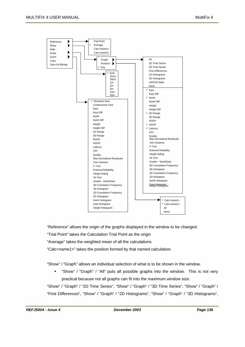
MULTIFIX 4 USER MANUAL MultiFix 4
REFJ500A - Issue 4 December 2003 Page 136
Reference Show Hide Scale Zoom Copy Save As Bitmap
Trial Point Average
Calc<name1>Calc<name2>
GraphPosition Key
Auto
50cm1m2m5m10m50m
All2D Time Series3D Time SeriesFirst Differences 2D Histograms3D HistogramsUKOOA StatsNone
Standard ViewCompressed ViewEast East DiffNorth
Height Diff2D Range3D RangePDOP HDOP LatencynSV Max Normalised ResidualsUnit VarianceF-Test External ReliabilityHeight AidingW-TestScatter - North/East3D Cumulative Frequency3D Histogram2D Cumulative Frequency2D HistogramNorth HistogramEast HistogramHeight Histogram
Calc<name1> Calc<name2> AllNone
North DiffHeight
20cm
EastEast DiffNorth
Height Diff2D Range3D RangePDOPHDOPLatencynSV
Max Normalised Residuals Unit VarianceF-TestExternal ReliabilityHeight AidingW-TestScatter - North/East3D Cumulative Frequency 3D Histogram2D Cumulative Frequency 2D HistogramNorth HistogramEast HistogramHeight Histogram
North DiffHeight
Quality
Quality
“Reference” allows the origin of the graphs displayed in the window to be changed.
“Trial Point” takes the Calculation Trial Point as the origin
“Average” takes the weighted mean of all the calculations
“Calc<name1>” takes the position formed by that named calculation.
“Show” / “Graph” allows an individual selection of what is to be shown in the window.
“Show” / “Graph” / “All” puts all possible graphs into the window. This is not very
practical because not all graphs can fit into the maximum window size.
“Show“ / “Graph“ / “2D Time Series“, “Show“ / “Graph“ / “3D Time Series“, “Show“ / “Graph“ /
“First Differences“, “Show“ / “Graph“ / “2D Histograms“, “Show“ / “Graph“ / “3D Histograms“,

MULTIFIX 4 USER MANUAL MultiFix 4
REFJ500A - Issue 4 December 2003 Page 137
and “Show“ / “Graph“ / “UKOOA Stats“ are all quick ways of making a reduced graph
selection.
“Show“ / “Graph“ / “2D Time Series“ is the default selection when the window is first
opened. This option includes the time series plots East, North, 2D Range, HDOP,
Latency and nSV
“Show” / “Graph” / “3D Time Series” option opens East, North, Height, 3D Range,
PDOP, Latency and nSV.
“Show“ / “Graph“ / “First Differences“ opens East Diff, North Diff and Height Diff.
“Show“ / “Graph“ / “2D Histograms“ opens Scatter – North/East, 2D Cumulative
Frequency, 2D Histogram, North Histogram and East Histogram.
“Show“ / “Graph“ / “3D Histograms“ opens Scatter – North/East, 3D Cumulative
Frequency, 3D Histogram, North Histogram, East Histogram and Height Histogram.
“Show” / “Graph” / “UKOOA Stats” opens Max. Normalised Residuals, Unit Variance,
F-Test, External Reliability, Height Aiding and W-Test.
“Show” / “Graph” / “None” switches all of the current graph displays off.
A tick against the graph name indicates it is included in the window. Individual graphs can be
added or removed from the window by clicking their individual names.
“Show“ / “Position“ defaults with All calculations selected for inclusion in the graphs. The data
for each calculation is colour coded and the key legend box shows the colours used against
the calculation names.
“Show“ / “Position“ / “All“ toggles all available calculations on.
“Show“ / “Position“ / “None“ toggles all available calculations off.
“Show“ / “Key“ turns the key legend box off and on.
Hide will close the graph that the mouse cursor is over when the right mouse button is clicked.
“Scale” can be set to Auto, 20cm, 50cm, 1m, 2m, 5m, 10m or 50m metres. Auto ensures that
graphs re-scale to show all the data over the last 60 minutes. Setting a scale distance will
affect those graphs where either the X or Y axis (or in the case of the scatter plot both X and
Y axes) is a distance. Graphs showing HDOP, PDOP Latency and nSV (number of satellites)
will not be affected by selecting the scale.
“Zoom” defaults to the Standard View in which each graph has X and Y axis labels. This
limits the number of graphs that can be shown in the window. Selecting the Compressed
View option removes the space between the graphs and the axis labels. Those labels are

MULTIFIX 4 USER MANUAL MultiFix 4
REFJ500A - Issue 4 December 2003 Page 138
then shown in the key legend box. Alternatively a single graph can be selected which will fill
the whole window. This can also be achieved by double clicking on the required graph when
in the standard view.
An example of the Compressed View display is shown below. The scale of the graphs is
included in the key legend box in addition to the mouse cursor position, in terms of X and Y of
the graph the cursor is over.
If a graph is to be viewed in more detail it can be selected individually in the Zoom selection
menu. Any graph can be called up and it will fill the window, it does not need to be already
open. To zoom into a graph that is already displayed double-click on the desired graph. To
revert to the original display double-click on the graph again.
The graphs available are: -
East ................................... is a times series plot of the difference in Eastings between the
calculated Eastings and the graph’s Eastings origin.

MULTIFIX 4 USER MANUAL MultiFix 4
East Diff .
epoch.
North.................................... is a time series plot of the difference in Northings between the
calculated Northings and the graph’s Northings origin.
is a times series plot of the difference in Northings epoch to
calculated Height and the graph’s Height origin.
eight Diff............................ is a times series plot of the difference in Height epoch to epoch.
.............. is a time series plot of the two dimensional radial distance
een each calculation’s position and the origin position.
alculation’s position and the origin position.
plot of the Positional Dilution of Precision value
tion
......... is a time series plot of the Horizontal Dilution of Precision value
tion
TCM Type 1
fixed at 30 seconds.
SV...................................... is a time series plot of the number of satellites used in a
est Normalised residual for the
selection calculation.
Variance....................... is a time series plot of the unit variance
............. is a time series plot of the F-test
.................... is a time series plot indicating if the solution is in height aiding
mode or not.
W-Test…………………….... is a time series plot of the W-test. The W-test result is either a
pass or fail
Scatter – North/East ............ is a scatter plot two dimensional display of the calculated
positions with respect to the origin of the plot.
............................ is a times series plot of the difference in Eastings epoch to
North Diff ........................... .
epoch.
Height .................................. is a time series plot of the difference in Height between the
H
2D Range ..............
betw
3D Range ............................ is a time series plot of the three dimensional radial distance
between each c
PDOP .................................. is a time series
for each calcula
HDOP .........................
for each calcula
Latency................................ is a time series plot of the age of the most recent R
(Type 48, 49, 50 for XP) message received prior to the time each
calculated position was formed. It’s Y axis does not re-scale it is
n
calculation
Quality………………………..is a time plot of the Qual value in the “View” \ “Calc” \ “Status”
dialogue
Max. Normalised Residuals. is a time series plot of larg
Unit
F-Test .....................
External Reliability............... is a time series plot of the largest error, in 2D, that might result
due to an undetected outlier existing in the calculation.
Height Aiding ...
REFJ500A - Issue 4 December 2003 Page 139

MULTIFIX 4 USER MANUAL MultiFix 4
REFJ500A - Issue 4 December 2003 Page 140
3D Cumulative Frequency... is a graph showing the percentage of the time over the last 60
minutes that the three dimensional radial distance has been with
n metres of the origin position. The 1 and 2 sigma lines are
shown.
2D Cumulative Frequency... is a graph showing the percentage of the time over the last 60
minutes that the two dimensional radial distance has been with n
metres of the origin position. The 1 and 2 sigma lines are shown.
3D Histogram ...................... is a histogram of the three dimensional radial distance between
each calculated position and the origin position.
2D Histogram ...................... is a histogram of the two dimensional radial distance between
each calculated position and the origin position.
North Histogram .................. is a histogram of the difference in Northings between each
calculated position and the origin’s Northings
East Histogram.................... is a histogram of the difference in Eastings between each
calculated position and the origin’s Eastings
Height Histogram................. is a histogram of the difference in Height between each
calculated position and the origin’s Height.
Remember that the time constant for the data in all these graphs is 60 minutes.
4.3.6.7. Event Log
“View” \ “Event Log”
This dialogue shows a history of events that have occurred since MultiFix was started. The
type of events that can be seen are shown below:
“Receiver Interface” – “Receiver input data failed”, “Receiver input data OK”.
“Almanac Applet” – “Satellite health change”.
“Datagram Monitor” – “Datagram error”.
“Orbit Correction Applet” – “Source changeover”, “RTCM data failed”, “RTCM data
OK”.

MULTIFIX 4 USER MANUAL MultiFix 4
REFJ500A - Issue 4 December 2003 Page 141
“RTCM Station XXXXX : Ident XXX” – “Input data OK”, “Input data failed”.
“XP Calculation” – “Transition Completed”
The Event Log will also be saved as a text file in the folder where the current MultiFix 4
configuration file is saved.
The file will be named with the format:
<ConfigFileName>_<YYYYMMDD>_EventLog.txt
e.g. Setup001_20030401_EventLog.txt

MULTIFIX 4 USER MANUAL MultiFix 4
REFJ500A - Issue 4 December 2003 Page 142
4.3.7. OPTIONS
LockColourHide ToolbarTrial Point WarningRinex
Setup001 - MultiFix 4 MultiFix3 File Config Logging Action View Options Tools Window Help
LockColourHide ToolbarTrial Point WarningRinex
Setup001 -Fix
File Config Logging Action View Options Tools Window Help
Type 16 AlertEvent Logger
4.3.7.1.1.Lock
“Options” \ “Lock”
If the Lock option is chosen “File” and Config” are removed from the menu bar. Whilst locked,
“Options” \ “Lock” changes to “Options” \ “Unlock”. This reinstates “File” and Config” if
selected.
4.3.7.2. Colour
“Options” \ “Colour”
If different colour schemes are
required they can be set up here.
Ensure that a false impression is
not given when changing the
colour coding, in particular
relating to errors.
Some of the selections do not
affect all view windows.
• “Main”
“Background” and “Text” change the windows background and text colours.
“Neutral” is used in the Latency window to show period when update may be
expected.
“Link” is not currently used.
• “Error”.
Various windows have stages of error state, these colours relate to them.
“Good”, “Bad” and “Warning”.
• “Miscellaneous”
“Output” as seen in the IO status and IO Scroller windows.
“Missing” as seen in the Latency and Constellation windows.

MULTIFIX 4 USER MANUAL MultiFix 4
“Out of Range” as seen in the Latency and Constellation windows when a satellite is
low the mask.
4.3.7.3. Hid
be
e Tool Bar
“Options” \ “Hide Tool Bar”
This will hide the shortcut toolbar displayed at the top of the MultiFix screen.
hen hidden the option will change to “show toolbar” which will return the toolbar to the
creen when selected.
4.3.7.4. Trial Point Warning
W
s
“Options” \ “Trial Point Warning”
00km a warning dialogue will be
e user if they wish to
licking [Update now] will update the
gnore] will retain the old value.
ogue by checking the “Do not display future
d by selecting Trial Point warning from the options
enu.
ue entered in “Config” \ “Calc” \ “Settings” and the
calculation value that is held in the configuration file. Even if an incorrect value for the trial
point is retained the calculation will continue using an up to date position. The stored position
is only modified if the user enters a new trial point position.
4.3.7.5. Rinex
When enabled, MultiFix will check the entered trial point value against the current position. If
the trial point is in error of more than
2
displayed, asking th
update the trial point.
C
entered trial point to the user current location. [I
This feature can be disabled from within the dial
warning”. The feature can be re-enable
M
MultiFix utilises two trial points, the val
“Options” \ “Rinex”
This enables or disables the Rinex data logging facility, accessible from the “Logging” \
“Rinex” menu, see section 4.3.4. When disabled the Rinex option will be not be shown in the
logging menu.
REFJ500A - Issue 4 December 2003 Page 143

MULTIFIX 4 USER MANUAL MultiFix 4
REFJ500A - Issue 4 December 2003 Page 144
4.3.7.6. Type 16 Alert
“Options” \ “Type 16 Alert”
If the user does not wish to be warned automatically of any Type 16 messages received then
the alert dialogue box can be disabled.
See section 4.3.6.5.5 for more details of the Type 16 alert dialogue.
The messages will continue to be displayed in the Type 16 history window and written to the
Type 16 log file.
If the alert dialogue is disabled a note is written to the log file stating that the feature has been
disabled.
A tick mark will appear next to “Type 16 Alert” if it is currently enabled.
4.3.7.7. Event Logger
“Options” \ “Event Logger”
If the “Event Logger” option is ticked in the “Options” menu then a dialogue box, shown
above, will appear automatically to warn the user of any event changes. The warning
dialogue will remain on screen until the [acknowledge] button is clicked.
A list of events displayed is shown in Section 4.3.6.7.

MULTIFIX 4 USER MANUAL MultiFix 4
REFJ500A - Issue 4 December 2003 Page 145
4.3.8. TOOLS
Position Viewer Wizard
Setup001 - MultiFix 4 MultiFix3 File Config Logging Action View Options Tools Window Help
Position Viewer Wizard
Setup001 -Fix
File Config Logging Action View Options Tools Window Help
Save Almanac to File
4.3.8.1. Position Viewer Wizard
“Tools” \ “Position Viewer Wizard”
Position Viewer enables the user to compare outputs from MultiFix with data from other
systems, such as the Fugro 90964 GLONASS unit, and to automatically select the most
stable solution. The Position Viewer Wizard is designed to co-ordinate the configuration of
MultiFix 4 and the Position Viewer application.
The wizard operates as a series of dialogues. Note that if at anytime an incorrect selection
has been made, use [<Back] to retrace the steps through the wizard and make the correction
1) Position Viewer Configuration
Enter a title for the configuration. This will be
the name of the configuration file in MultiFix.
Check the tick boxes for the features that you
require.
The “External Positioning / Glonass Source”
option is designed for use with the Fugro
90964 but applies to any external NMEA input.
The ”DP Features” option will enable the auto select mode for selecting the most stable
solution.
The ”Composite DP Output” option will enable the Position output option in Position Viewer.
Click [Next>] to continue.

MULTIFIX 4 USER MANUAL MultiFix 4
osition Viewer.
cket port number you wish to use
ee section 4.3.3.1.2 for more details about
both MultiFix and Position Viewer. It will
g inputs and outputs in both applications. The ZeroLink data format
lternative inputs can be set up within Position
lick [Next>] to continue.
sition Viewer DP
uto Selector.
Set the alarm thresholds in metres and the
istory”, which is the period over which the
stability will be determined. (see Position
Viewer manual for more details)
Click [Next>] to continue.
2) Position Viewer Positions
Select the positions you wish to export to
P
Define the so
to transfer the data
(s
sockets).
This will set up the required socket configurations in
also create correspondin
is used so only one data port is required.
Click [Next>] to continue.
3) Position Viewer Glonass
Here the physical data port for the external
input is defined. An NMEA GGA string from a
Fugro 90964 is expected.
A
Viewer. See the Position Viewer manual for
further details.
C
4) Po
Enter the initial reference position for the DP
A
“H
REFJ500A - Issue 4 December 2003 Page 146
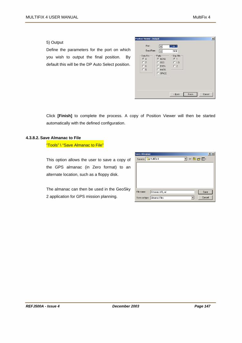
MULTIFIX 4 USER MANUAL MultiFix 4
5) Output
Define the parameters for the port on which
you wish to output the final position. By
default this will be the DP Auto Select position.
4.3.8.2. Sa o File
Click [Finish] to complete the process. A copy of Position Viewer will then be started
automatically with the defined configuration.
ve Almanac t
“Tools” \ “Save Almanac to File”
the GPS almanac (in Zero format) to an
he almanac can then be used in the GeoSky
This option allows the user to save a copy of
alternate location, such as a floppy disk.
T
2 application for GPS mission planning.
REFJ500A - Issue 4 December 2003 Page 147
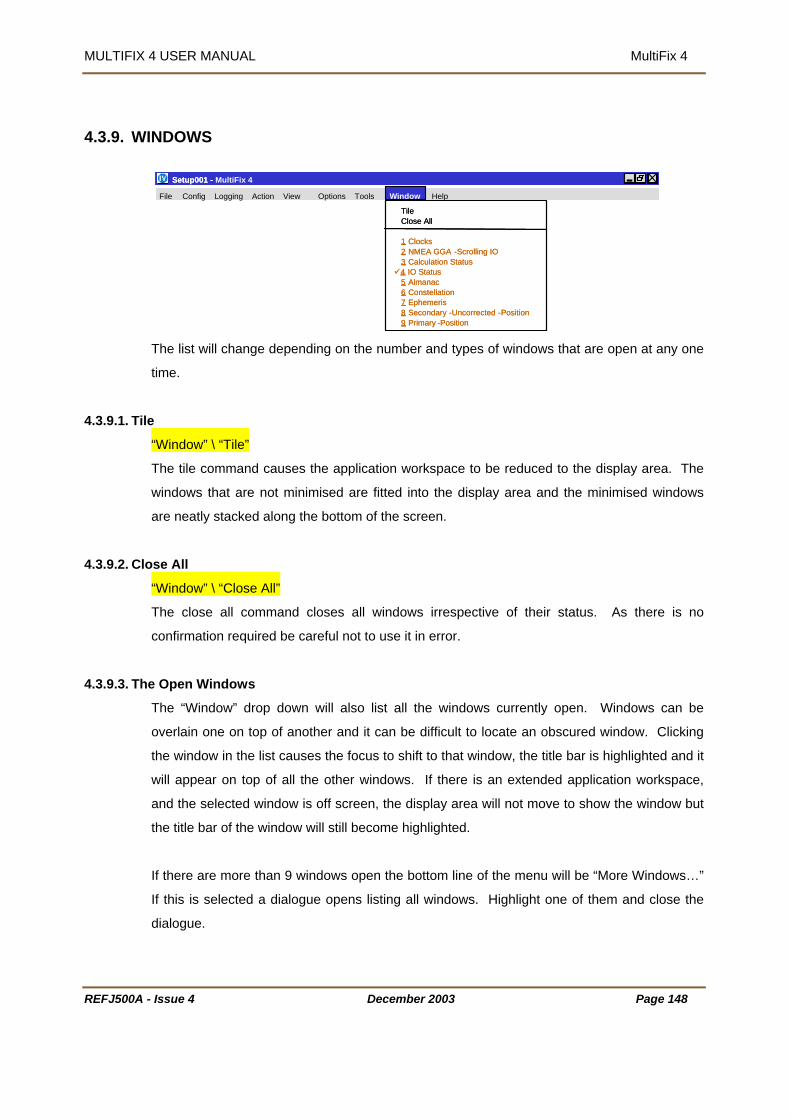
MULTIFIX 4 USER MANUAL MultiFix 4
REFJ500A - Issue 4 December 2003 Page 148
4.3.9. WINDOWS
TileClose All
1 Clocks2 NMEA GGA -Scrolling IO3 Calculation Status4 IO Status5 Almanac6 Constellation7 Ephemeris8 Secondary -Uncorrected -Position9 Primary -Position
Setup001 - MultiFix 4 MultiFix3 File Config Logging Action View Options Tools Window Help
TileClose All
1 Clocks2 NMEA GGA -Scrolling IO3 Calculation Status4 IO Status5 Almanac6 Constellation7 Ephemeris8 Secondary -Uncorrected -Position9 Primary -Position
Setup001 - Fix
File Config Logging Action View Options Tools Window Help
The list will change depending on the number and types of windows that are open at any one
time.
4.3.9.1. Tile
“Window” \ “Tile”
The tile command causes the application workspace to be reduced to the display area. The
windows that are not minimised are fitted into the display area and the minimised windows
are neatly stacked along the bottom of the screen.
4.3.9.2. Close All
“Window” \ “Close All”
The close all command closes all windows irrespective of their status. As there is no
confirmation required be careful not to use it in error.
4.3.9.3. The Open Windows
The “Window” drop down will also list all the windows currently open. Windows can be
overlain one on top of another and it can be difficult to locate an obscured window. Clicking
the window in the list causes the focus to shift to that window, the title bar is highlighted and it
will appear on top of all the other windows. If there is an extended application workspace,
and the selected window is off screen, the display area will not move to show the window but
the title bar of the window will still become highlighted.
If there are more than 9 windows open the bottom line of the menu will be “More Windows…”
If this is selected a dialogue opens listing all windows. Highlight one of them and close the
dialogue.

MULTIFIX 4 USER MANUAL MultiFix 4
REFJ500A - Issue 4 December 2003 Page 149
4.3.10.HELP
Contents...Dongle...Performance
Setup001 - MultiFix 4 MultiFix3 File Config Logging Action View Options Tools Window Help
Setup001 - File Config Logging Action View Options Tools Window Help
About...
4.3.10.1.Help
“Help” \ “Contents…”
Launches the online help.
4.3.10.2.Dongle
“Help” \ “Dongle…”
Provides the information stating:
• Which programs the DK2 is authorised to run
• The time limit of the dongle
• The amount of use the dongle has already had.
At all times MultiFix 4 is being run the dongle is
required in the computer’s parallel port. If it is
removed the program shuts down and an error
message is posted.
If the time limit of the dongle expires the program
shuts down and an expiry message is posted.
It is possible to revalidate the dongle by running the PROLIVE program and making a call to
the Technical Support Group. The same program plus a telephone call can also be used to
terminate a dongle so that it is no longer valid and no longer re-charged.
The list in the above dialogue requires refers to certain programs in the Zero Suite. SKYNET
is a differential correction monitoring package, GENESIS is a Long Range RTK system that
uses a similar software package to MultiFix, and RXV is a program called RECEIVER
VERIFY which is described in Section 6.
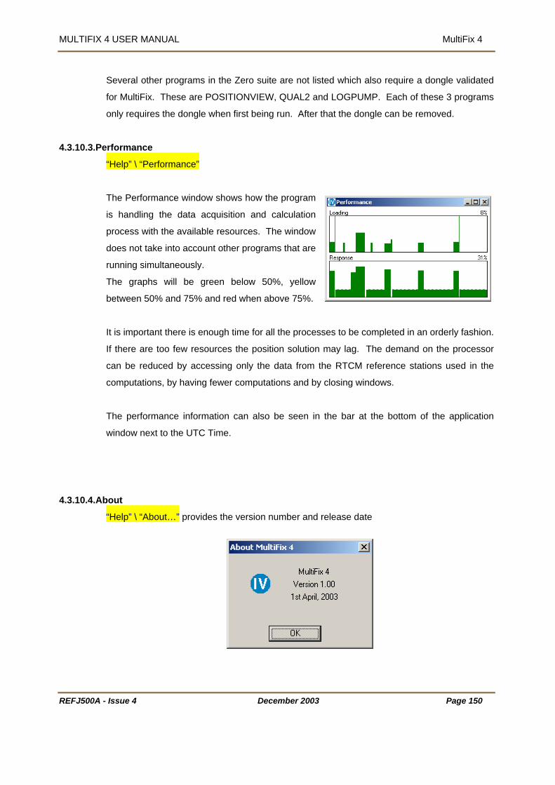
MULTIFIX 4 USER MANUAL MultiFix 4
Several other programs in the Zero suite are not listed which also require a dongle validated
re POSITIONVIEW, QUAL2 and LOGPUMP. Each of these 3 programs
4.3.10.3.Performance
for MultiFix. These a
only requires the dongle when first being run. After that the dongle can be removed.
“Help” \ “Performance”
The Performance window shows how the program
is handling the data acquisition and calculation
process with the available resources. The window
does not take into account other programs that are
running simultaneously.
The graphs will be green below 50%, yellow
between 50% and 75% and red when above 75%.
It is important there is enough time for all the processes to be completed in an orderly fashion.
y lag. The demand on the processor
computations, by having fewer computations and by closing windows.
4.3.10.4.Ab
If there are too few resources the position solution ma
can be reduced by accessing only the data from the RTCM reference stations used in the
The performance information can also be seen in the bar at the bottom of the application
window next to the UTC Time.
out
“Help” \ “About…” provides the version number and release date
REFJ500A - Issue 4 December 2003 Page 150

MULTIFIX 4 USER MANUAL MultiFix 4
4.4. MU
LTIFIX 4 REPLAY
Setup001 - MultiFix 4 MultiFix3 File Config Logging Action View Options Tools Window Help
Play Stop
Setup001 - Fix
File Config Logging Action View Options Tools Window Help
Pause Fast ForwardFast Rewind Rewind StepStep Backward Next File
Replay
e to re-inject that same information into
l read the Zero Log (*.zer) files recorded by
ultiFix 4 and create outputs, which MultiFix 4 can accept as source data. In Replay mode
s in pseudo-real time. See Section 4.3.4.1 on Zero logging
og files be available but it is
le, which has
een used for Zero logging. See Section 4.3.2.2 on page 51.
When Raw Zero files have been logged it is possibl
MultiFix 4 by using the Replay option. Replay wil
M
MultiFix 4 performs re-computation
on page 79.
To optimise the Replay operation not only must the Zero L
essential that the MultiFix 4 configuration and other associated files are available as well.
To replay raw GPS and RTCM data in MultiFix 4 first open the configuration fi
b
Select the logged files that are to be replayed in “Logging” \ “Zero” \ “Edit” either by typing in
facility. This provides the Browse for Folder
ired destination folder. When
ultiFix 4 but they are
y Qual 2 and Position Viewer. To replay position log files another Zero application, LOG
the destination or by using the [Browse…]
dialogue. The path can be defined by clicking on the des
selecting files of different days for replay the Zero files have to be consecutive.
MultiFix 4 will recognize raw data input, thus any of the logging modes can be selected as
long as the *.zer files contain raw data. Positions are not accepted by M
b
PUMP has to be used. See Section 8.
When the path and mode of logging have been selected click [OK].
REFJ500A - Issue 4 December 2003 Page 151

MULTIFIX 4 USER MANUAL MultiFix 4
REFJ500A - Issue 4 December 2003 Page 152
The Replay menu and toolbar buttons will only be visible if “Replay” has been enabled under
the Options menu.
Be aware that the online operation mode will stop when entering Replay mode. The program
provides a warning, clicking [OK] activates the new menu.
While in replay mode the GPS receiver type cannot be changed and new SkyFix Decoder
input cannot be defined. Evidently the selected GPS receiver cannot be configured from the
Action menu.
The “View” \ “IO” \ “Status” window will only show output data as raw data is not being
received via physical ports or sockets but from the replay application within MultiFix 4. GPS
Receiver input data will not be displayed in “View” \ “IO” \ “Scroller”, RTCM input and Output
strings however will be available.
In replay mode all other options and view windows will be available similarly to online
operation. New calculations can be defined, as well as the calculation settings can be
modified and new output strings can be generated. Even RINEX files can be logged in
pseudo-real time.
4.4.1. Replay options
Replay has 9 menu items, “Play”, “Stop”, “Pause”, “Fast Forward”, “Fast Rewind”, “Rewind”,
“Step”, “Step Backward” and “Next File”. Each has a toolbar button equivalent.
“Play” starts the replay process and advances through the selected files with
normal speed.
“Stop” resets the file reading to the start of the selected files.
“Pause” will arrest the replay process until another command is given.

MULTIFIX 4 USER MANUAL MultiFix 4
“Fast Forward” will advance in replay with high speed.
“Fast Rewind” will advance backwards in the calculation with high speed.
“Rewind” will advance in the files backwards with normal speed.
“Step” will move the pseudo-real time calculation one step forward feeding the
next epoch GPS data or RTCM correction into the filter.
“Step Backward” will move one step back in the calculation.
“Next File” will jump to the start of the next file. If replaying the last file “Next File”
will jump to the end of the file.
The progress of the replay can be followed in “View” \ “Files”.
By disabling “Replay” under the Options menu the online operation mode restarts.
REFJ500A - Issue 4 December 2003 Page 153

MULTIFIX 4 USER MANUAL SkyLink
5. SKYLINK 5.1. INTRODUCTION
SkyLink is one of a series of applications available under the group name Zero. SkyLink is an
RTCM transfer / modification program.
The RTCM Type 1 corrections that are generated at reference stations are contaminated by
several error components, a major one of which is Ionospheric delay. Many DGPS firmware /
software systems have used and still use the Klobuchar Ionospheric delay model to correct
this error. This model is updated periodically but is not responsive to the current short-term
variability caused by high levels of sunspot activity. An alternative to using the Klobuchar
model methodology is to assess the Ionospheric delay element of every pseudo-range
between each in view satellite and each reference station and between each in view satellite
ach pseudo-range and RTCM correction
can then be removed and an Iono-free solution of position derived. This methodology
requires a dual frequency receiver on the mobile and at each reference station. The
reference station then needs to either
1. Modify each correction in the Type 1 messages or
2. Output a message that contains corrections to be applied to the corrections in the Type 1
messages.
SkyFix Premier uses the latter approach and provides satellite/reference station Ionospheric
delay information in Type 55 messages. Type 55 messages are Fugro proprietary messages,
Type 15 is the standard message for the dissemination of Ionospheric delay information.
Given a dual frequency mobile receiver and RTCM type 55 messages, MultiFix 4 can provide
a complete Iono-free solution of position, however some firmware / software can not,
therefore SkyLink has been produced to improve the DGPS positioning performance of those
firmware / software systems.
SkyLink has been produced primarily to
1. Generate Iono corrected Type 1 messages
2. Generate Type 15 messages from the Type 55 messages that are supplied by Fugro's
SkyFix Premier service.
However, as will be seen, its functionality has been extended beyond its primary purpose.
equired, starts with a decision on the
required outputs. This in turn requires knowledge of the firmware / software that is to receive
the SkyLink output. SkyLink has 5 output mode options.
and the mobile. The Ionospheric delay element of e
What RTCM inputs and GPS receiver (if any) are r
REFJ500A - Issue 4 December 2003 Page 154

MULTIFIX 4 USER MANUAL SkyLink
Option 1 does not modify the messages but will add a carriage return to the end of each
message. Therefore if the recipient firmware / software already performs Iono-free position
calculations using dual frequency receiver data with RTCM Type 1and Type 55 messages but
needs a carriage return terminator on each RTCM message, select Option 1 with carriage
return.
If the recipient firmware / software
1. Already performs DGPS Iono-free position calculations using Type 1 and dual frequency
receiver data but
2. Needs Type 15 rather than Type 55 messages,
select Option 2 (with or without carriage return).
If the recipient firmware / software
1. Does not compute an Iono-free solution,
2. Does NOT use the Klobuchar model but
3. Will perform a DGPS calculation using Type 1 messages,
then SkyLink can modify the corrections in the RTCM Type 1 messages to remove the
Ionospheric delay between the satellites and the reference stations and between the satellites
and the mobile. In which case select Option 3 (with or without carriage return).
If the recipient firmware / software does not
1. Does not compute an Iono-free solution,
2. Does use the Klobuchar model and
3. Will perform a DGPS calculation using Type 1 messages,
the RTCM Type 1 messages to remove the
Ionospheric delay between the satellites and the reference stations and between the satellites
and the mobile and then add the Klobuchar values that the recipient firm/software is going to
remove. In which case select Option 4 (with or without carriage return).
If the recipient firmware / software does not apply any Ionospheric corrections at all and there
is no broadcast Ionospheric correction data available, then assuming SkyLink knows where it
is, it can modify the corrections in the Type 1 messages with data taken from its own
Klobuchar model. In which case select Option 5 (with or without carriage return).
While there can be any number of outputs using any of the options, the output with the most
stringent option governs the inputs and GPS receiver required by SkyLink.
then SkyLink can modify the corrections in
REFJ500A - Issue 4 December 2003 Page 155

MULTIFIX 4 USER MANUAL SkyLink
REFJ500A - Issue 4 December 2003 Page 156
Option Output RTCM Input GPS Receiver
1 No change Any RTCM Type
messages without
Carriage Return
terminator
Not essential
2 Type 55 to Type 15 Must have RTCM Type
55 messages, (will also
pass on other types as
received).
Not essential
3 Corrected Type 1 Must have RTCM type
1, 2, 3 and 15 or 55
messages.
Dual frequency Ashtech
ZX Sensor, MS750 or
Trimble 4000SSE/SSI
4 Corrected Type 1 (Reverse
Klobuchar)
Must have RTCM type
1, 2, 3 and 15 or 55
messages
Dual frequency Ashtech
ZX Sensor, MS750 or
Trimble 40000SSE/SSI
5 Apply Differential Klobuchar RTCM Type 1
messages
Single frequency Ashtech
DG16, Trimble 4000DS (or
Dual frequency MS750 or
Trimble 40000SSE/SSI)
SkyLink takes in RTCM SC104 Version 2 differential correction messages. These may be
from any number of RTCM Correction delivery systems. As seen above it also takes in Fugro
Proprietary RTCM Type 55 Ionospheric range corrections. These are generated at selected
SkyFix Premier reference stations and are broadcast via the Fugro global network of high and
low power L Band beams. The Type 55 format has recently been modified; the program is
able to take in either style.
• There is no limit on the number of RTCM correction delivery systems.
• There is no limit on the number of RTCM differential reference stations.
• There is no limit on the number of outputs.
• There is no limit on the number of view windows
• The view windows can be customised
The text in this manual conforms to certain conventions
4. All command buttons are shown bold and bracketed with square brackets e.g. [OK],

MULTIFIX 4 USER MANUAL SkyLink
5. When a keyboard key is represented, it is shown bold and bracketed by greater than and
lesser than symbols e.g. <spacebar>.
or edit control slots are shown in normal text in
quotations, e.g. “IO Channel:”
6. Direct quotations from dialogues
REFJ500A - Issue 4 December 2003 Page 157

MULTIFIX 4 USER MANUAL SkyLink
5.2. CONFIGURATION
igure 7
Figure 8
5.2.1. HARDWARE INTERCONNECTION
F
REFJ500
Example Configuration for SkyLink Options 1 or 2
RTCM
DATA
LINK
RTCM DECODERSKYLINK
COMPUTER
RTCM In
DecoderTest
Message
Optional
RTCM Out
DUAL FREQUENCY
Example Configuration for SkyLink Options 3 and 4
GPS ANTENNA
12V DC POWER SUPPLY
DUAL FREQUENCY RECEIVER Ashtech ZX Sensor, or
SKYLINK
RTCM DATA LINK
RTCM DECODER
COMPUTER
RTCM In
Optional Decoder
Test Message
RTCM Out
Trimble MS750
A - Issue 4 December 2003 Page 158
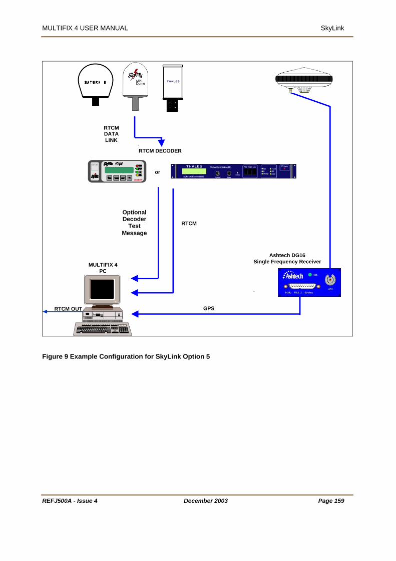
MULTIFIX 4 USER MANUAL SkyLink
REFJ500A - Issue 4 December 2003 Page 159
Ashtech DG16 Single Frequency Receiver MULTIFIX 4
PC
RTCM DATA LINK
RTCM DECODER
Optional Decoder
Test Message
or
RTCM
GPSRTCM OUT
Figure 9 Example Configuration for SkyLink Option 5
MULTIFIX 4 USER MANUAL SkyLink
REFJ500A - Issue 4 December 2003 Page 160
5.2.2. HARDWARE REQUIREMENT SkyLink requires the following:
A PC running Windows 98, Windows 2000 or Windows NT.
The PC will preferably be a PII or faster. A graphics resolution of at least 1024 by 768 pixels
is recommended in order to achieve maximum clarity of all the graphics displays.
For the installation of the software the PC requires a CD-ROM drive. It is possible to create
installation floppy discs from the installation menu on the CD but 8 floppies are needed.
Depending on the output option SkyLink may need a single frequency GPS receiver, such as
the Ashtech DG16 or a dual frequency GPS receiver, such as the Ashtech ZX Sensor.
Again depending on the output option, assuming data is not being input or output over
network sockets, the PC may need 1 COM port for two-way communications to the GPS
receiver and a second COM port for the input of RTCM corrections. Given that the second
port is for input only, by using a special breakout cable, the same COM port used for the
RTCM input can also be used for the output of RTCM messages.
If there is more than one RTCM delivery system or data is to be output on several ports, then
additional COM ports may be required. These can be any proprietary asynchronous serial
board (or PCMCIA card) the Windows drivers for which, allow the board’s/card’s ports to be
mapped as additional COM ports.

MULTIFIX 4 USER MANUAL SkyLink
REFJ500A - Issue 4 December 2003 Page 161
5.2.3. GPS RECEIVER CONFIGURATIONS
5.2.3.1. Ashtech (Thales Navigation) Receivers
Ashtech receivers can be controlled either from within MultiFix or externally using the Evaluate software
from Thales Navigation.
Evaluate must be used to establish and configure baud rates, but once communications have been
established between the PC and MultiFix then MultiFix can complete the configuration process.
5.2.3.1.1.Configuration from within MultiFix
Assuming communications have been established between MultiFix and the
GPS receiver then the receiver can be configured automatically by MultiFix.
The Command “Action” \ “Configure Ashtech” will launch the receiver
configuration dialogue.
Select Set default configuration to complete the receiver configuration.
Note that if using a Z Family receiver then the Baud Rate must be set to a
minimum of 38400 due to the large amount of data output from the receiver.
See section 4.3.5.6 for more details.
5.2.3.1.2.Ashtech Evaluate Configuration
Direct configuration of Ashtech receivers is usually via the Ashtech Evaluate program; alternatively they
can be configured using a terminal program. The following relates to Ashtech Evaluate which is included
on the MultiFix 4 installation CD.
Sample configuration files are also available on this CD.
After installing the Evaluate software start the program
by clicking the Ashtech Evaluate icon in the start menu.
The user will be asked to choose a start up option.
Select “Connect to GPS Receiver” and click [OK].

MULTIFIX 4 USER MANUAL SkyLink
REFJ500A - Issue 4
In the Connection Parameters dialogue select the PC Port, tick the “Initialize from file:” box, remove the
tick from all other boxes and select and the preferred initialisation file.
Pre-configured initialisation files can be found on the MultiFix 4
installation CD. These files must first be copied to the Evaluate \
Receiver folder.
Alternatively a file can be created from the text below. Re-name the
new text file with a *.gps extension and place it in the Evaluate \
Receiver folder.
The benefit of using an initialisation file is that all configuration
commands are sent to the receiver in a preferred sequence and can be followed by a command that
saves all these settings in the battery backed-up memory of the receiver.
On clicking [Connect], the software will try to
establish connection with the receiver.
If the PC COM port settings do not match the
port setting of the internal port on the GPS
receiver, Evaluate will report that the GPS
receiver is not responding.
By selecting the [AutoSelect], Evaluate will cycle through all possible COM port parameter settings and
will report if it finds the current receiver. Evaluate will then connect with the newly found settings.
If no matching port
is powered on.
December 2003 Page 162
settings are found, investigate all cable connections and make sure that the receiver
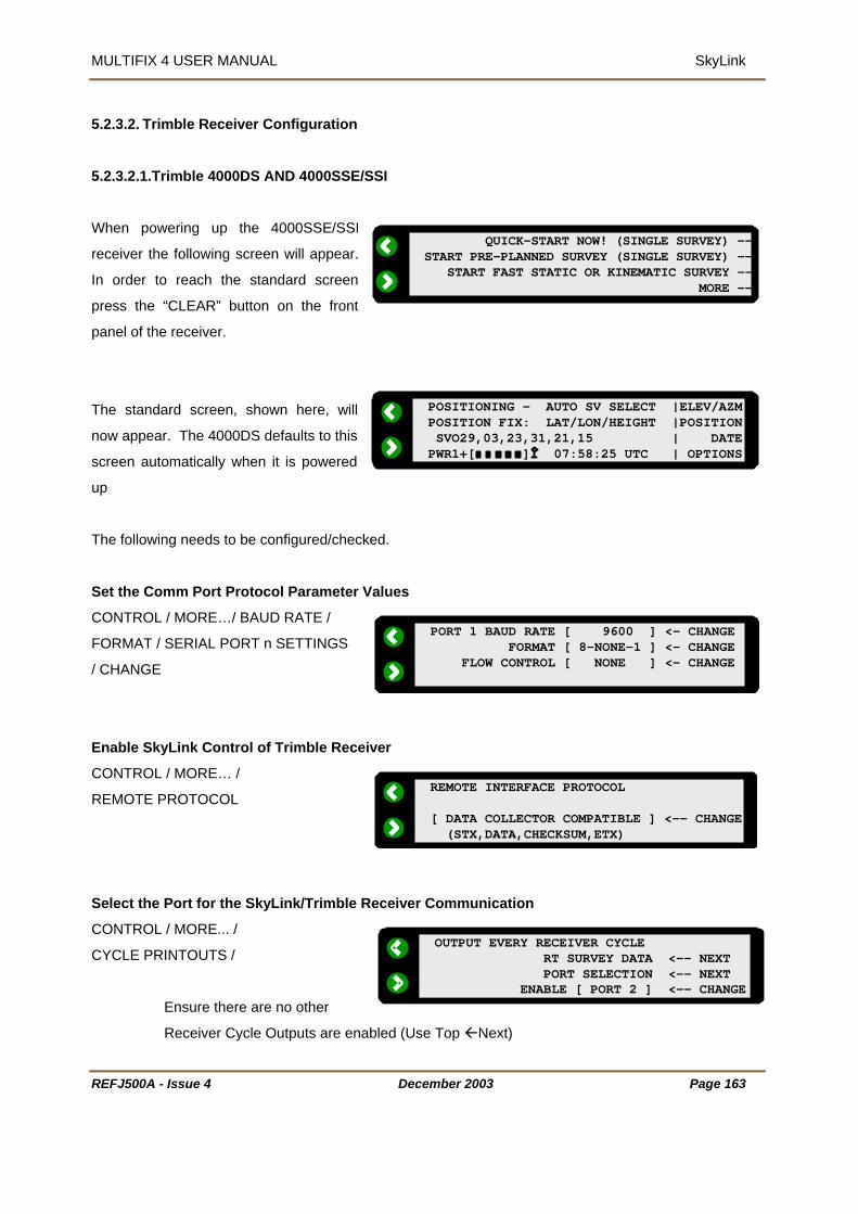
MULTIFIX 4 USER MANUAL SkyLink
REFJ500A - Issue 4
PORT 1 BAUD RATE [ 9600 ] <- CHANGE
QUICK-START NOW! (SINGLE SURVEY) --START PRE-PLANNED SURVEY (SINGLE SURVEY) -- START FAST STATIC OR KINEMATIC SURVEY -- MORE --
POSITIONING - AUTO SV SELECT |ELEV/AZMPOSITION FIX: LAT/LON/HEIGHT |POSITION SVO29,03,23,31,21,15 | DATEPWR1+[ ] 07:58:25 UTC | OPTIONS
5.2.3.2. Trimble Receiver Configuration
5.2.3.2.1.Trimble 4000DS AND 4000SSE/SSI
When powering up the 4000SSE/SSI
receiver the following screen will appear.
In order to reach the standard screen
press the “CLEAR” button on the front
panel of the receiver.
The standard screen, shown here, will
now appear. The 4000DS defaults to this
screen automatically when it is powered
up
The following needs to be configured/checked.
Set the Comm Port Protocol Parameter Values
CONTROL / MORE…/ BAUD RATE /
FORMAT / SERIAL PORT n SETTINGS
/ CHANGE
Enable SkyLink Control of Trimble Rece
CONTROL / MORE… /
REMOTE PROTOCOL
Select the Port for the SkyLink/Trimble R
CONTROL / MORE... /
CYCLE PRINTOUTS /
Ensure there are no other
Receiver Cycle Outputs are ena
FORMAT [ 8-NONE-1 ] <- CHANGE FLOW CONTROL [ NONE ] <- CHANGE
REMOTE INTERFACE PROTOCOL
iver
[ DATA COLLECTOR COMPATIBLE ] <-- CHANGE (STX,DATA,CHECKSUM,ETX)
OUTPUT EVERY RECEIVER CYCLE
eceiver Communication
b
December 2003 Page 163
RT SURVEY DATA <-- NEXT PORT SELECTION <-- NEXT ENABLE [ PORT 2 ] <-- CHANGE
led (Use Top Next)

MULTIFIX 4 USER MANUAL SkyLink
REFJ500A - Issue 4
OUTPUT EVERY RECEIVER CYCLE RT SURVEY DATA <-- NEXT CONCISE FORMAT <-- NEXT ENABLE [ ON ] <-- CHANGE
NMEA-183 ENABLE[ OFF ] <-- CHANGE
DIFFERENTIAL STATION <-- MORERTCM-104 INPUTS [ ON/AUTO ] <-- CHANGE PORT SELECT [ PORT 1 ] <-- CHANGE FORMAT [ VERSION 2 ] <-- CHANGE
Select the Format for the SkyLink/Trimble Receiver Communication
CONTROL / MORE... /
CYCLE PRINTOUTS /
(Use Middle Next)
***Ensure the Receiver is Outputting Positions if SkyLink Option 4 or 5 Outputs required***
CONTROL / MORE... /
CYCLE PRINTOUTS /
(Use Middle Next)
(Optional) Select the Port for the Receiver’s Input of RTCM Corrections
CONTROL/
RTCM-104 INPUT
Check that there are No Other Outputs Enabled On the SkyLink/Trimble Receiver Communication
Port
CONTROL / MORE… /
NMEA-183 OUTPUT
Check that the SV Sync Time is set to 1 s
CONTROL / MORE… /
MASKS/SYNC TIME
If you are using a 4000SSE/SSI receiver
CONTROL / MORE…/
L1 / L2 OPERATION
Only the L2 code can be disabled. Ensur
above shows the screen display for the 40
4000 SSE receiver differs slightly: the L2 T
OUTPUT EVERY RECEIVER CYCLE RT SURVEY DATA <-- NEXT OUTPUT POSITIONS <-- NEXT ENABLE [ ON ] <-- CHANGE
OUTPUT CONTROL ALM[ OFF ] <-- CHANGE BWC[ OFF ] <-- CHANGE MORE
econd
POSITIONING MASKS/SYNC TIME: |
December 2003 Page 164
ensure that it is set to dual frequency mode
e that both the L1 and L2 codes are enabled. The diagram
00 SSI receiver in dual frequency mode. The display on the
RACKING codes will read P,X instead of P,E.
ELEVATION MASK = +10º | MINUS PDOP MASK = 07.0 | SV SYNC TIME = 001.0 SEC | ACCEPT
L1/L2 TRACKING: P,C/A-CODE | L1 TRACKING P,E-CODE | L2 TRACKING
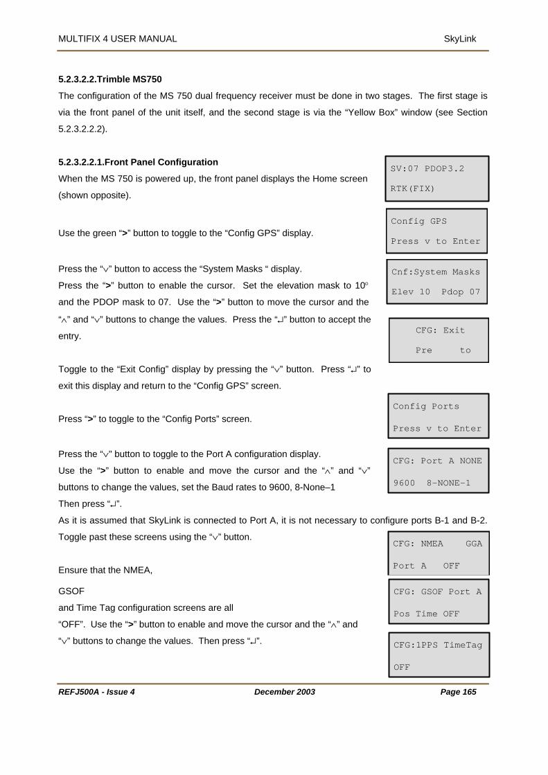
MULTIFIX 4 USER MANUAL SkyLink
REFJ500A - Issue 4 December 2003
5.2.3.2.2.Trimble MS750
The configuration of the MS 750 dual frequency receiver must be done in two stages. The first stage is
via the front panel of the unit itself, and the second stage is via the “Yellow Box” window (see Section
5.2.3.2.2.2).
5.2.3.2.2.1.Front Panel Configuration
When the MS 750 is powered up, the front panel displays the Home screen
(shown opposite).
Use the green “>” button to toggle to the “Config GPS” display.
Press the “∨” button to access the “System Masks “ display.
Press the “>” button to enable the cursor. Set the elevation mask to 10°
and the PDOP mask to 07. Use the “>” button to move the cursor and the
“∧” and “∨” buttons to change the values. Press the “↵” button to accept the
entry.
Toggle to the “Exit Config” display by pressing the “∨” button. Press “↵” to
exit this display and return to the “Config GPS” screen.
Press “>” to toggle to the “Config Ports” screen.
Press the “∨" button to toggle to the Port A configuration display.
Use the “>” button to enable and move the cursor and the “∧” and “∨”
buttons to change the values, set the Baud rates to 9600, 8-None–1
Then press “↵”.
As it is assumed that SkyLink is connected to Port A, it is not necessary to co
Toggle past these screens using the “∨” button.
Ensure that the NMEA,
GSOF
and Time Tag configuration screens are all
“OFF”. Use the “>” button to enable and move the cursor and the “∧” and
“∨” buttons to change the values. Then press “↵”.
SV:07 PDOP3.2
RTK(FIX)
n
Config GPS
Press v to Enter
Cnf:System Masks
Elev 10 Pdop 07
CFG: Exit
Pre to
Config Ports
Press v to Enter
figure ports B-1 and B-2.
CFG: Port A NONE
9600 8-NONE-1
CFG: NMEA GGA
Port A OFF
CFG: GSOF Port A
Pos Time OFF
Page 165
CFG:1PPS TimeTag
OFF
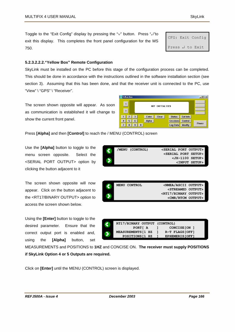
MULTIFIX 4 USER MANUAL SkyLink
REFJ500A - Issue 4
Toggle to the “Exit Config” display by pressing the “∨” button. Press “↵”to
exit this display. This completes the front panel configuration for the MS
750.
5.2.3.2.2.2.“Yellow Box” Remote Configuration
SkyLink must be installed on the PC before this stage of the configuration process can be completed.
This should be done in accordance with the instructions outlined in the software installation section (see
section 3). Assuming that this has been done, and that the receiver unit is connected to the PC, use
“View” \ “GPS” \ “Receiver”.
The screen shown opposite will appear. As soon
as communication is established it will change to
show the current front panel.
Press [Alpha] and then [Control] to reach the / MENU (CONTROL) screen
Use the [Alpha] button to toggle to the
menu screen opposite. Select the
<SERIAL PORT OUTPUT> option by
clicking the button adjacent to it
The screen shown opposite will now
appear. Click on the button adjacent to
the <RT17/BINARY OUTPUT> option to
access the screen shown below.
Using the [Enter] button to toggle to the
desired parameter. Ensure that the
correct output port is enabled and,
using the [Alpha] button, set
MEASUREMENTS and POSITIONS to 1HZ
if SkyLink Option 4 or 5 Outputs are req
Click on [Enter] until the MENU (CONTRO
/MENU (CONTROL) <SERIAL PORT OUTPUT> <SERIAL PORT SETUP> <JX-1100 SETUP> <INPUT SETUP>
CFG: Exit Config
Press ↵ to Exit
December 2003 Page 166
and CONCISE ON. The receiver must supply POSITIONS
uired.
L) screen is displayed.
MENU CONTROL <NMEA/ASCII OUTPUT> <STREAMED OUTPUT> <RT17/BINARY OUTPUT> <CMR/RTCM OUTPUT>
RT17/BINARY OUTPUT (CONTROL) PORT[ A ] CONCISE[ON ]MEASUREMENTS[1 HZ ] R-T FLAGS[OFF] POSITIONS[1 HZ ] EPHEMERIS[OFF]
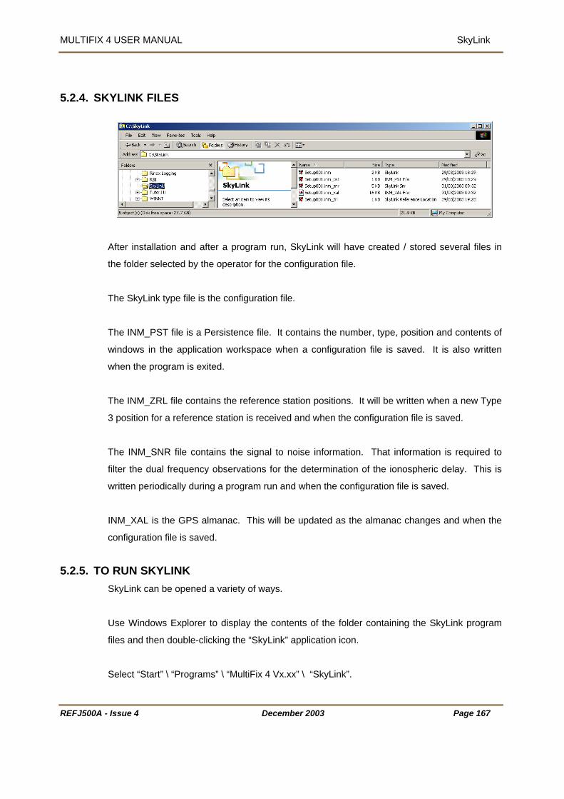
MULTIFIX 4 USER MANUAL SkyLink
INK FILES
5.2.4. SKYL
After installation and after a program run, SkyLink will have created / stored several files in
the folder selected by the operator for the configuration file.
The SkyLink type file is the configuration file.
M_PST file is a Persistence file. It contains the number, type, position and contents of
lication workspace when a configuration file is saved. It is also written
and when the configuration file is saved.
ic delay. This is
ritten periodically during a program run and when the configuration file is saved.
he GPS almanac. This will be updated as the almanac changes and when the
5.2.5. TOkyLink can be opened a variety of ways.
elect “Start” \ “Programs” \ “MultiFix 4 Vx.xx” \ “SkyLink”.
The IN
windows in the app
when the program is exited.
The INM_ZRL file contains the reference station positions. It will be written when a new Type
3 position for a reference station is received
The INM_SNR file contains the signal to noise information. That information is required to
filter the dual frequency observations for the determination of the ionospher
w
INM_XAL is t
configuration file is saved.
RUN SKYLINK S
Use Windows Explorer to display the contents of the folder containing the SkyLink program
files and then double-clicking the “SkyLink” application icon.
S
REFJ500A - Issue 4 December 2003 Page 167
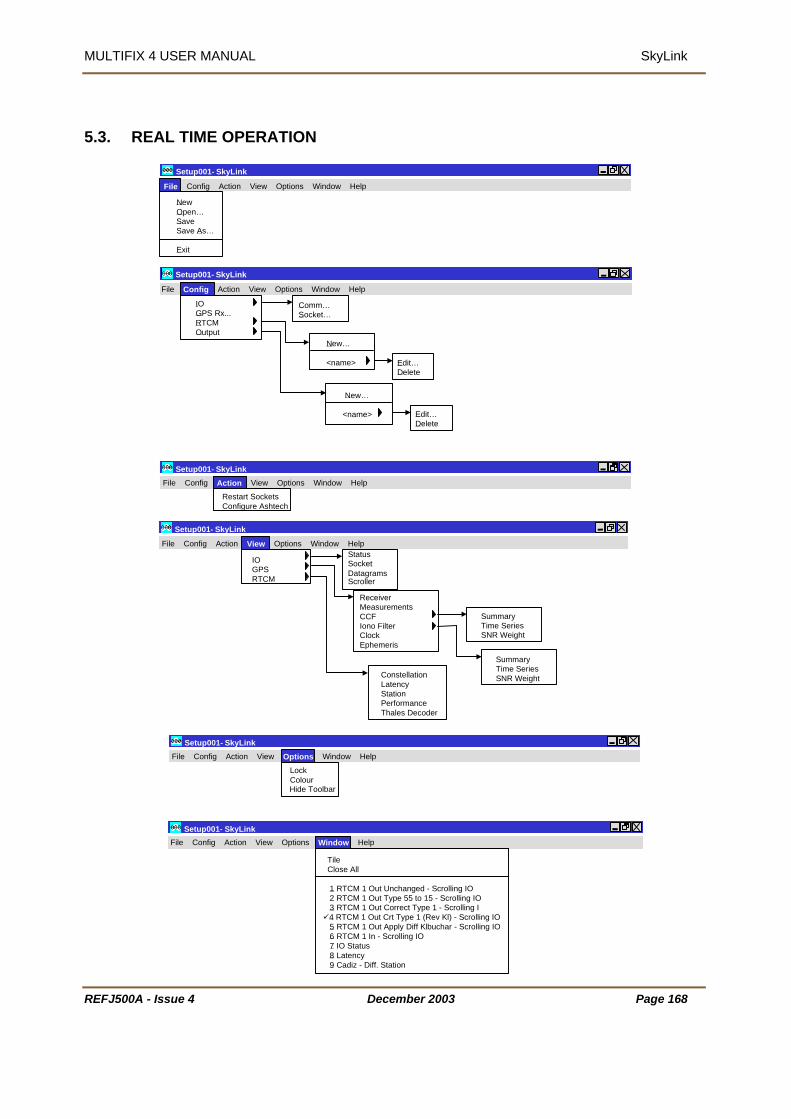
MULTIFIX 4 USER MANUAL SkyLink
REFJ500A -
5.3. REAL TIME OPERATION
Setup001- SkyLink
New Open…SaveSave As…
Exit
File Config Action View Options Window Help
Setup001- SkyLink
IOGPS Rx...RTCMOutput
Comm…Socket…
New…
<name> Edit…Delete
New…
<name> Edit…Delete
File Config Action View Options Window Help
Setup001- SkyLink
Restart Sockets Configure Ashtech
Setup001- SkyLink File Config Action View Options Window Help
I
IOGPSRTCM
StatusSocketDatagrams
ReceiverMeasurementsCCFIono FilterClockEphemeris
ConstellationLatencyStationPerformanceThales Decoder
SummaryTime SeriesSNR Weight
SummaryTime SeriesSNR Weight
File Config Action View Options Window Help
Scroller
Setup001- SkyLink
LockColourHide ToolbarFile Config Action View Options Window Help
Setup001- SkyLink
ssue 4 December 2003 Page 168
TileClose All
1 RTCM 1 Out Unchanged - Scrolling IO2 RTCM 1 Out Type 55 to 15 - Scrolling IO3 RTCM 1 Out Correct Type 1 - Scrolling I4 RTCM 1 Out Crt Type 1 (Rev Kl) - Scrolling IO5 RTCM 1 Out Apply Diff Klbuchar - Scrolling IO6 RTCM 1 In - Scrolling IO7 IO Status8 Latency9 Cadiz - Diff. Station
File Config Action View Options Window Help

MULTIFIX 4 USER MANUAL SkyLink
Figure 10 S
Setup001- SkyLink
REFJ500A -
kyLink Menu Layout
DonglePerformance
File Config Action View Options Window Help
About
Issue 4 December 2003 Page 169

MULTIFIX 4 USER MANUAL SkyLink
5.3.1. FIL
E
New Open…SaveSave As…
Exit
Setup001- SkyLink
File Config Action View Options Window Help
t the bottom of the “File” menu is a list of recently used configuration files. Clicking on one
f these files opens up the chosen configuration.
5.3.1.1. New
A
o
“File” \ “New…”
o start a new SkyLink configuration select this option.
e aware that starting a new configuration will close the existing configuration and the
5.3.1.2. Open
T
B
program will cease outputting data.
“File” \ “Open…”
When opened the program does not know which configuration file to open. Assuming a
se this facility to select it.
iers in a file
eader. They also have a configuration
though created by a different program version.
previously prepared configuration exists, u
The configuration files have program
name and version identif
h
file version number. The program will
not allow configuration files to be
opened that are not compatible with the
version of RxV that is currently being
run. However if the configuration file
version is the same they can be used even
File open can also be accomplished using the button.
REFJ500A - Issue 4 December 2003 Page 170

MULTIFIX 4 USER MANUAL SkyLink
ve 5.3.1.3. Sa
“File” \ “Save”
A configuration is not automatically saved as changes are made, therefore use this facility to
update the configuration file to the current status. If the set up is being undertaken for the first
me and the configuration does not have an identity, the use of “File” \ “Save” will call up the
equires a name to be entered for the RxV files. Once a
onfiguration has been named, use of “File” \ “Save” performs the save without calling up the
he name of the current configuration file appears in the application workspace title bar. If
at file name has an * appended
lso be accomplished using the
ti
Save As dialogue. That dialogue r
c
Save As dialogue.
T
configuration changes are made that have not been saved, th
to it. After a File \Save the * is removed. File saving can a
button.
5.3.1.4. Save As
“File” \ “Save As…”
If the current configuration is to be saved but not at the exp
configuration files, use the “File” \ ”Save As…” option. This
and leaves the previous files as they were. The program imm
new files as the current configuration fil
ense of overwriting the existing
creates new configuration files
ediately commences to use the
es.
for the new configuration file. If
existing files.
.3.1.5. Exit
The Save As dialogue requires the operator to enter a name
an existing file name is entered, the program will overwrite the
5
“File” \ “Exit”
This exit route is immediate if no configuration file is loaded.
Confirmation is required if a configuration file is in use. The user will be prompted to save the
configuration if they have not already done so.
xited using the
If the program is e button when the current configuration has not been
saved, a dialogue is presented asking whether to save the configuration prior to exit or
whether to cancel the exit. If there have been no configuration changes then the program will
terminate immediately.
REFJ500A - Issue 4 December 2003 Page 171

MULTIFIX 4 USER MANUAL SkyLink
5.3.2. CONFIGURE
IOGPS Rx...RTCMOutput
Comm…Socket…
Setup001- SkyLink
New…
<name> Edit…Delete
New…
<name> Edit…Delete
File Config Action View Options Window Help
5.3.2.1. IO
5.3.2.1.1.C
omm
“Config” \ “IO” \ “Comm…”
Earlier it was explained that
be run after installation to de
page 13). The
the “Programs” / “MultiFix 4 Vx.xx” / “IO Config” applet needed to
fine what ports the computer has available (see section 3.4 on
parameters selected there determine the dialogue box that is presented when
onfig” \ “IO” \ “Comm…” is selected..
Highlight one of the ports to be used and click
dit]. This opens another dialogue box for
Click the [Enable] button to activate the port
and set the Baud Rate, Data Bits, Parity and
Stop Bits.
“C
[E
setting the port parameter settings.
REFJ500A - Issue 4 December 2003 Page 172

MULTIFIX 4 USER MANUAL SkyLink
REFJ500A - Issue 4 December 2003 Page 173
5.3.2.1.2.Sockets
“Config” \ “IO” \ “Socket…”
To be able to distribute and receive data over a network via sockets assumes each computer
has Transmission Control Protocol / Internet Protocol (TCP/IP) installed. Sockets have the
advantage over COM ports in that two or more programs can access the same data.
Sockets can transfer data between programs running on different computers or between two
or more programs running on the same computer. (If a standalone (non-networked) computer
running Windows NT is used and the data is to be shared between multiple programs running
on that PC then the MS Loopback Adapter network adapter must be installed).
The TCP/IP protocol is a family of protocols that allow Internet data communication. Included
in that family are two transport layer protocols, the Transport Control Protocol (TCP) and the
User Datagram Protocol (UDP).
The Transport Control Protocol establishes sessions between a Server and however many
Clients that are accessing that Server. There is continual presence checking and
acknowledging between each Server/Client pairs with messages always received in the order
they were issued. A Server does not have control of the number of Clients that access the
socket on which data is being presented. (It is often perceived that the Server provides data
and the Client receives data, but once the connection is established the link is two-way).
The User Datagram Protocol does not have the end-to-end checking overhead of the TCP.
Instead packets of data are simply issued to the Internet in either broadcast mode, where any
networked computer on the LAN can receive them, or in addressed mode where the data
packets have headers specifying the addressees for whom the packets are intended. There
is no guarantee with this protocol that the messages will arrive in the order they were issued.
When setting up “Ribbons” to output datagrams a time interval can be specified to prevent
data becoming corrupted, see section 7.3.2.2 on “Ribbons”. Broadcast datagrams cannot
pass routers linking Local Area Networks (LAN) unless specifically configured.
For most situations where Local Area Networks are involved Server / Client TCP sockets are
the best choice Internet transport protocols.
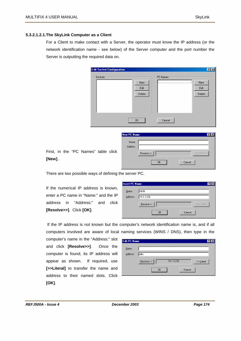
MULTIFIX 4 USER MANUAL SkyLink
5.3.2.1.2.1
First, in the “PC Names” table click
[New]..
There are two possible ways of defining the server PC.
If the numerical IP address is known,
enter a PC name in “Name:” and the IP
address in “Address:” and click
[Resolve>>]. Click [OK].
If the IP address is not known but the computer’s network identification name is, and if all
computers involved are aware of local naming services (WINS / DNS), then type in the
computer’s name in the “Address:” slot
and click [Resolve>>]. Once the
computer is found, its IP address will
appear as shown. If required, use
[>>Literal] to transfer the name and
address to their named slots. Click
[OK].
.The SkyLink Computer as a Client
For a Client to make contact with a Server, the operator must know the IP address (or the
network identification name - see below) of the Server computer and the port number the
Server is outputting the required data on.
REFJ500A - Issue 4 December 2003 Page 174

MULTIFIX 4 USER MANUAL SkyLink
It is normal in a network for computers to be allocated new IP addresses when the PC is
rted. If the Client PC has a numerical entry for the address and the Server’s address
not be able to re-locate it. If the Client PC has the name of the Server PC
the address slot, it will automatically search to re-locate the Server PC by name. Assuming
found, the Client PC will obtain the Server PC’s current address.
heck the “Client” radio button and select the ”PC Name:”
nter the number of the port on which the Server PC is
me if
5.3.2.1.2.2
re is
r computer to the PC table; the
rogram already knows the computer’s IP address. This
IO” \
1.2 on page 173.
ame
t on.
5.3.2.1.2.3
5.3.2.1.2 that the User Datagrams Protocol allows packets of data
be broadcast or to be sent to specific addresses without the overheads associated with the
CASTING
xV cannot give multiple addresses to packets of data so if information is to be made
resta
has changed, it will
in
it is
In the “Sockets” table click [New].
C
of the server.
E
presenting the data. Change the socket’s default na
required.
.The SkyLink Computer as a Server
If the Log Pump computer is to be a server then the
no need to add the Socce
p
can be seen in the window called up by “Config” \ “
“Sockets”, see 5.3.2.
In the “Sockets” table click [New]. Give the socket a n
and enter the Port number that the data will be outpu
Click [OK] to exit.
.Datagrams
It was explained in section
to
Transport Control Protocol.
BROAD
R
available to more than one computer in datagrams it must be broadcast on a particular port.
A computer that is broadcasting on a port also listens to all data packets that are received on
that port.
REFJ500A - Issue 4 December 2003 Page 175

MULTIFIX 4 USER MANUAL SkyLink
DATAGRAMS TO/FROM A SPECIFIC PC
number and the PC are identified.
” radio
st.
C requires that the Internet address
f that PC should already have been identified. See
tion of
Once the PC has been entered in the “PC Names:” table click [New] in the “Sockets” table.
G
ente
i
sele
To transmit to or to receive from a specific computer, (which may itself be broadcasting), a PC
must be set up with a datagram socket where the port
To broadcast datagram packets, click the “Datagram
button and select “Broadcast” from the “PC Name:” li
To target one specific P
o
Section 5.3.2.1.2.1 on page 174 for an explana
adding PCs.
ive the socket a name,
r the Port number and
n the “PC Name list
ct the PC.
Click [OK] to exit.
Having set up sockets, the Edit Socket Configuration dialogue now shows the connection(s).
REFJ500A - Issue 4 December 2003 Page 176

MULTIFIX 4 USER MANUAL SkyLink
REFJ500A - Issue 4 December 2003 Page 177
5.3.2.2. GPS Receiver
“Config” \ “GPS Rx…”
This calls up the Edit GPS Receiver.
Enter a receiver name in the “Name:” box. If this is left
blank MultiFix will automatically assign a suitable name
(e.g. 4000 DS (Trimble)). As with other name labels the
program does not use it for receiver recognition purposes.
In the “Type:” section select the receiver that MultiFix 4 is
to use.
There are various possible selections.
• Z Family (Ashtech)* are dual frequency receivers.
• DG16 (Ashtech) )* is a single frequency receiver
• G12 (Ashtech) )* is a single frequency receiver
• GG24 (Ashtech) * is a single frequency receiver and is fitted in the Fugro 90964 units
• 4000 Series (Trimble) refers to either a single frequency 4000DS or a dual frequency
SSE/SSI
• MS750 (Trimble) is a dual frequency receiver
• BD750 (Trimble) is a dual frequency receiver
• BD112 (Trimble)* is a single frequency receiver board fitted to the 90938/F112 SkyFix
decoder.
• DSM212 (Trimble)* is a single frequency receiver.
• DSM (Trimble)* is a single frequency receiver board fitted to 90938/M SkyFix decoder.
• SK8 (Trimble)* is a single frequency receiver board, but not recommended for offshore
work. It has not been tested for full operation.
• Millennium (NovAtel) is a dual frequency receiver
• Receiver Server is used when the data is not live from an external receiver but is taken
from raw data log files.
• Receiver Verify is used for interfacing to the Receiver Verify (RxV) Module.
In the “IO Channel:” section select the port on which the receiver data is input.
The Ancillary Receiver option is used for synchronising GPS measurements over a data link.
This is not currently used.

MULTIFIX 4 USER MANUAL SkyLink
When one of the receivers marked above with an asterix is selected, “Configure TSIP” or
ure Ashtech” becomes available under the “Action” menu. This allows the receiver to
utput the correct data for MultiFix 4. The other Trimble Receivers are
“Receiver”).
configure.
“Config
be configured to o
configurable using the Yellow box interface (“View” / “GPS” /
Other manufacturers’ receivers require third party software to
REFJ500A - Issue 4 December 2003 Page 178

MULTIFIX 4 USER MANUAL SkyLink
5.3.2.3. RTCM
“Config” \ “RTCM”
5.3.2.3.1.New
“Config” \ “RTCM” \ “New”
\ “RTCM” there is a sub-menu option “New…” Click on that to make a
e.
select the “IO Channel:”
ontains a drop down list of all the
urces. When one of
arried by that system and the [New], [Edit] and
kyFix Beams:” contains a drop down list of all the
urces. When one of
stations that
carried by that system and the [New], [Edit] and
[Delete] buttons are lost..
It is then necessary to switch on any stations to be
used by clicking the check box next to the station’s
name.
If MultiFix 4 is being used with a non-satellite based RTCM delivery system, or station names
or numbers have been changed, a manually compiled list can be made. To add reference
stations manually in the “Station” table of the New RTCM Input dialogue leave the “SkyFix
Beam:” set to User Defined and click the [New] button.
From “Config”
connection to a RTCM sourc
In the “New RTCM Input” dialogue give the RTCM
source a name and
“SkyFix Beams:” c
satellite based Fugro RTCM so
those sources is selected, the dialogue is
automatically populated with all the stations that
c
[Delete] buttons are lost.
If no name is given MultiFix will assign a suitable
name automatically
“S
satellite based Fugro RTCM so
those sources is selected, the dialogue is
automatically populated with all the
REFJ500A - Issue 4 December 2003 Page 179

MULTIFIX 4 USER MANUAL SkyLink
The program requires the station ID code number. A name is also required for identity
data.
ssuming the RTCM source is outputting more
dd the
tation to the list, repeat the process to add the
is planned, three criteria
ust be met to be viable.
ced
essages from one or
more reference stations must be available.
Type 15 or 55 Ionospheric error information
938 or 2403 Decoder is supplying the RTCM corrections then it is possible to
configure the decoder to output Bit Error Rate and Signal Voltage status information on a
separate port (usually Port 4). If this data is required then check the “Exists” box and select
the port receiving the data. This in turn activates the “SkyFix Decoder” menu item under
“View” \ “Corrections”.
Click [OK] to accept the correction source.
If there is more than one RTCM correction delivery system add another new source and set
up using either of the two procedures above.
Assuming the RTCM interface has been established, the messages from the RTCM source
can be viewed to see the Reference Station numbers that the program is receiving, (see
Section 5.3.4.1.4.2190).
If the RTCM source is no longer in use, again use “Config” \ “RTCM” \ “<name>” and select
Delete. You will be asked to confirm or cancel the deletion. Clearly, an inappropriate deletion
could impact severely on the normal operation of the program.
purposes but is not significant in accessing the
A
than one station, after clicking [OK] to a
s
other required stations.
If Iono free operation
m
1. A dual frequency receiver must be interfa
to MultiFix 4.
2. RTCM Type 1, 2 and 3 m
3.
must also be available from the same RTCM reference stations.
If a Fugro 90
REFJ500A - Issue 4 December 2003 Page 180

MULTIFIX 4 USER MANUAL SkyLink
The program will take in any RTCM messages it receives on any RTCM IO Channel to which
access. It is possible that an RTCM source may contain only Type 55 messages. Such
a source will still need to be given an identity and an “IO Channel”. Each Type 55 message
contains Ionospheric delay information from one reference station. The station ID is also in
the message that is transmitted every 30 seconds. The sequence cycles through each of the
available reference station, so if 7 stations are contributing Type 55 messages the information
for each station will be updated every 3½ minutes.
5.3.2.3.2.Editing and Deleting
it has
“Config” \ “RTCM” \ “<name>” \ “Edit…” or “Delete”
With an RTCM source (or sources) now defined, when “Config” \ “RTCM” is selected, the
name (or names) given to the RTCM source(s) now appears in the sub-menu under the
asked to confirm or cancel the deletion. Be aware that an inappropriate
eletion could severely impact on the correct operation of the program.
“New… menu item.
If the set up requires changing then highlight the name of the source and then select the
“Edit…” option.
If the RTCM source is no longer in use, again use “Config” \ “RTCM” \ “<name>” and select
“Delete”. You will be
d
REFJ500A - Issue 4 December 2003 Page 181

MULTIFIX 4 USER MANUAL SkyLink
5.3.2.4. Outputs
“Config” \ “Output”
In common with RTCM sources once an output has been
defined it will appear by name in the menu drop down.
Highlighting the name then allows it to be edited or
deleted.
To create a new output select
“Config” \ “Output” \ “New…”
This calls up the dialogue shown opposite.
Enter a “Name” for the output.
Select the “RTCM Input” source.
Select the “IO Channel” via which the messages are to be sent.
e Return (CR) added to the end
f each of them.
Select whether the output messages need to have a Carriag
o
In the “Mode” table, select the required Option for output. The INTRODUCTION to this
manual has discussed the options, their impact, input and hardware requirements. Please
refer there for an explanation.
REFJ500A - Issue 4 December 2003 Page 182

MULTIFIX 4 USER MANUAL SkyLink
5.3.3.1. Re
5.3.3. ACTION
Restart Sockets Configure Ashtech
Setup001- SkyLink File Config Action View Options Window Help
start Sockets
“Action” \ “Restart Sockets”
On occasion heavy network traffic may lock up TCP\IP socket ports. This option will
without having to restart the software or editing the
5.3.3.2. Co
reinitialise all currently open sockets
configuration files.
nfigure Ashtech
“Action” \ “Configure Ashtech”
If an Ashtech GPS receiver has been selected for use with MultiFix
en the ”configure Ashtech” dialogue will be made available.
already been established
gured from within MultiFix.
Navigation) Receivers for
nication link with the GPS
er.
5.3.3.2.1.D
ton will send the basic command needed to configure
th
Assuming serial communications have
an Ashtech GPS Receiver can be confi
See section 4.2.4.1 Ashtech (Thales
details on how to a establish commu
Receiv
efault Ashtech configuration
Clicking on the [Set Default Config] but
the selected unit for use with MultiFix.
REFJ500A - Issue 4 December 2003 Page 183

MULTIFIX 4 USER MANUAL SkyLink
REFJ500A - Issue 4 December 2003 Page 184
5.3.3.2.2.Advanced Ashtech configuration
The [Advanced Config] Button will call up a
control menu.
[Refresh Settings] will update the display.
[Request Receiver Details] will interrogate
the GPS receiver settings and send
commands to the unit.
[Save Receiver Configuration] will save the
current setting to the battery powered RAM
on the receiver circuit board.
The “Send Command” dialogue allows the user to send additional commands to the GPS
receiver. Please refer to the appropriate Ashtech handbook for details of the available
commands.

MULTIFIX 4 USER MANUAL SkyLink
5.3.4. VI
EW
IOGPSRTCM
Setup001- SkyLink StatusSocketDatagrams
ReceiverMeasurementsCCFIono FilterClockEphemeris
ConstellationLatencyStationPerformanceThales Decoder
SummaryTime SeriesSNR Weight
SummaryTime SeriesSNR Weight
File Config Action View Options Window Help
nto
nother application.
ave As…” allows an html file of the view window to be saved. By default it will be placed in
ntains the Log Pump configuration file.
In common with many Windows programs, SkyLink allows display windows to be moved
outside the area displayed by the monitor. The application workspace automatically extends
and scroll bars are provided. The scroll bars allow the display area to move around the
extended application workspace. There is no limit on the number of windows of any type that
can be open in the application workspace. Multiple copies of the same window type can be
open. Indeed it will be seen that once a window is open some types of window allow further
selection of the data that is to appear in them.
Scroller
Right-mouse clicking many windows allows the user to customise the display. Where that
customisation is specific to the view window it will be mentioned in the relevant section
dealing with that window. However several windows share the same two facilities, to “Copy”
and to “Save As…”
“Copy” places a bitmap of the window onto the clipboard, from whence it can be pasted i
a
“S
the folder that co
REFJ500A - Issue 4 December 2003 Page 185

MULTIFIX 4 USER MANUAL SkyLink
Fi
Display Area
RE
gure 11 Windows Extending Beyond the Application Workspace
Most windows can be resized by clicking and dragging the corners or sides. Some windows
that contain text will wrap the text message into the available space. Other windows
containing text will simply be cropped as the window size reduces. Windows containing
graphical information will resize down to a minimum and will then either crop the information
or will introduce scroll bars.
Extended Application Workspace Horizontal Scroll Bar
Vertical Scroll Bar
Setup001- SkyLink File Config Action View Options Window Help
Loading 12% Response 5% 1:33:29 pm UTC
FJ500A - Issue 4 December 2003 Page 186

MULTIFIX 4 USER MANUAL SkyLink
5.3.4.1. Input / Output
“View” \ “IO”
There are three sub-menus and each will call a window to the SkyLink application workspace.
5.3.4.1.1.Status
“View” \ “IO” \ “Status”
The window indicates when there is port activity.
By default the window will contain the
iboard channels.
e blue vertical bars would be seen
A right-mouse click calls up the
[Channel] button. When this is
clicked the IO Status dialogue is
presented. This allows channels to
be selected or deselected from the status window.
In the IO Status window the latest time is in the centre
between the Input and Output columns. Each box indicates
when data has been input or output, over the last 5 seconds,
on that port by scrolling vertical bars from the centre to the
outside edges of the window. The box re-scales such that the
greatest data rate over the last 5 seconds is full scale. The
current bit rate is shown opposite the I/O channel name.
ports Log Pump knows to exist. The
“None” I/O Channel is at the top
followed by streamed socket
channels, datagram sockets and then
the COM and Dig
(When setting up Input / Output
channels there is the option to select
a dummy channel “None”. If selected
th
progressing across the None Output
box).
REFJ500A - Issue 4 December 2003 Page 187

MULTIFIX 4 USER MANUAL SkyLink
REFJ500A - Issue 4 December 2003
5.3.4.1.2.Sockets
“View” \ “IO” \ “Sockets””
A client socket can have three states,
Idle, Connecting and Connected.
Idle and Connecting will alternate while
connection is trying to be established. There will
also be a time countdown to the next attempt to
make contact.
A server socket can have two states,
Idle and Listening.
The Idle status is almost immediately replaced by Listening.
5.3.4.1.3.Datagrams
“View” \ “IO” \ “Datagrams”
The Datagram Status window lists all Datagrams in use. The IP address indicates to which
PC a link is in place or if it is transmitting a broadcast message. The “Packets In” and
“Packets Out” window indicates if the datagram is working. If you are receiving data only the
“Packets In” will increase. If you are transmitting to n PCs the “Packets In” will increase at n
times the rate of the “Packets Out”.
5.3.4.1.4.Scroller
“View” \ “IO” \ “Scroller”
Scroller is able to display any of the inputs and outputs. When first opened the display
defaults to showing the link from the first GPS receiver in the configuration list.. To change to
another IO Channel or to change the scrolling options, click the right mouse button.
This calls up a menu box, which has “Device”, “Freeze”,
“Clear” and “Show” as shown opposite. Device MS750
Page 188
FreezeClearShow
RTCM 1 In RTCM 1 Out Correct Type 1
Input Output Text Corrupt

MULTIFIX 4 USER MANUAL SkyLink
If “Device” is highlighted there is a sub-menu which lists the different input / outputs. Top of
the list are the names given to the each of the GPS receivers. This is followed by the input
from PDS.
If “Freeze” is selected the current window display is held and frozen appears in the windows
title bar. Clicking “Freeze” again unfreezes the display. “Clear” will remove all information
from the current window.
put”, “Output”, Text” and “Corrupt”. A
ck next to the option indicates that the relevant information is currently displayed in the
ssage is received or sent successfully a black
xt line is added as a label. Carriage return and line feed are shown in light grey.
e a lot of resources and should be closed when they are not required.
t is usual to turn off the “Input” (green) section.
5.3.4.1.4.1
“Show” brings up a new sub-menu with four options: “In
ti
Scroller window. These options may be toggled on/off by left clicking.
The text in the window is bottom justified and colour coded. Green indicates it has been
successfully decoded and passed all parity checks. Red indicates the data is corrupted.
Dark blue is reserved for outputs. When a me
te
Scroller windows us
For inputs i
.GPS Receiver
REFJ500A - Issue 4 December 2003 Page 189

MULTIFIX 4 USER MANUAL SkyLink
5.3.4.1.4.2.RTCM Input
5.3.4.1.4.3.Output Strings
REFJ500A - Issue 4 December 2003 Page 190
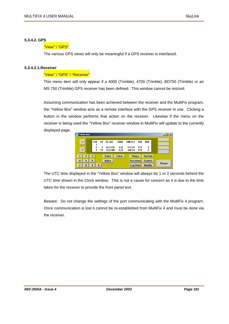
MULTIFIX 4 USER MANUAL SkyLink
S 5.3.4.2. GP
“View” \ “GPS”
The various GPS views will only be meaningful if a GPS receiver is interfaced.
5.3.4.2.1.R
eceiver
“View” \ “GPS” \ “Receiver”
This menu item will only appear if a 4000 (Trimble), 4700 (Trimble), BD750 (Trimble) or an
MS 750 (Trimble) GPS receiver has been defined. This window cannot be resized.
Assuming communication has been achieved between the receiver and the MultiFix program,
e “Yellow Box” window acts as a remote interface with the GPS receiver in use. Clicking a
window performs that action on the receiver. Likewise if the menu on the
receiver window in MultiFix will update to the currently
th
button in the
receiver is being used the “Yellow Box”
displayed page.
The UTC time displayed in the “Yellow Box” window will always be 1 or 2 seconds behind the
UTC time shown in the Clock window. This is not a cause for concern as it is due to the time
taken for the receiver to provide the front panel text.
ating with the MultiFix 4 program.
Beware: Do not change the settings of the port communic
Once communication is lost it cannot be re-established from MultiFix 4 and must be done via
the receiver.
REFJ500A - Issue 4 December 2003 Page 191

MULTIFIX 4 USER MANUAL SkyLink
5.3.4.2.2.Measurements
“View” \ “GPS” \ “Measurements”
The display shows the signal to noise (SNR) levels of each of the tracked satellites as a
button on a bar. The width of each bar shows the minimum and maximum over the last 60
updates. The button position shows the current value. The button will be Red when there are
<30 values in the filter, Yellow
when between 30 and 59 and
Green when 60 values have
not show the same information until the
least minimum and the greatest maximum to be
displayed.
are acquired and setting satellites are lost.
been obtained.
If two Measurement windows are opened they will
second Measurement window has received 60 updates.
The signal level may vary widely if the satellite is just rising, setting, or if high levels of
multipath are present.
The X-axis re-scales as a function of the
The Y-axis will re-scale as rising satellites
Satellites for which there is data from the GPS receiver will still appear in the window even if
they are disabled in “Action” \ “SV Status”.
If using a dual frequency receiver then SNR’s will be shown for L1 and L2.
REFJ500A - Issue 4 December 2003 Page 192
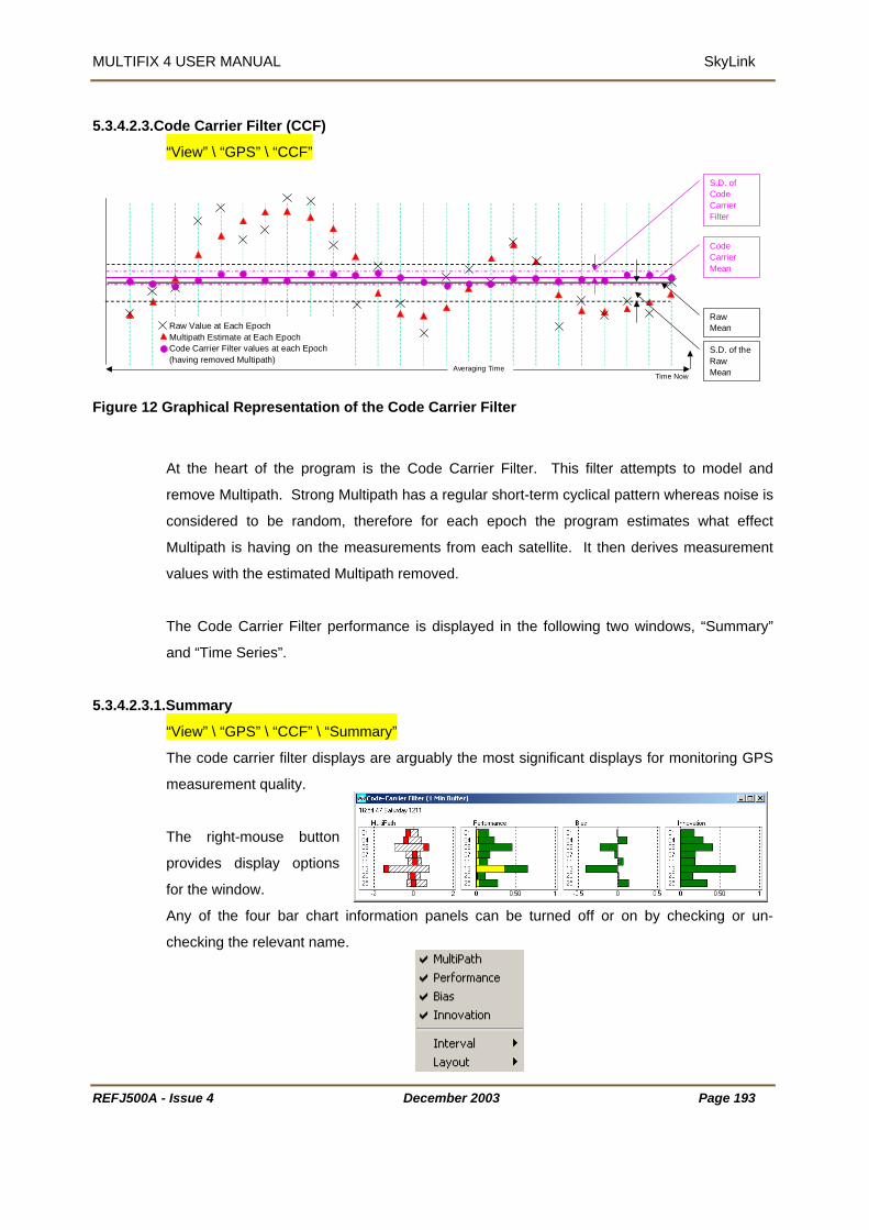
MULTIFIX 4 USER MANUAL SkyLink
5.3.4.2.3.Code Carrier Filter (CCF)
“View” \ “GPS” \ “CCF”
F
5
S.D. ofCode
R
igure 12 Graphical Representation of the Code Carrier Filter
At the heart of the program is the Code Carrier Filter. This filter attempts to model and
remove Multipath. Strong Multipath has a regular short-term cyclical pattern whereas noise is
considered to be random, therefore for each epoch the program estimates what effect
Multipath is having on the measurements from each satellite. It then derives measurement
values with the estimated Multipath removed.
The Code Carrier Filter performance is displa
and “Time Series”.
.3.4.2.3.1.Summary
yed in the following two windows, “Summary”
“View” \ “GPS” \ “CCF” \ “Summary”
The code carrier filter displays are arguably the most significant displays for monitoring GPS
measurement quality.
The right-mouse button
provides display options
for the window.
Any of the four bar chart information panels can be turned off or on by checking or un-
checking the relevant name.
Time Now
Raw Value at Each EpochMultipath Estimate at Each EpochCode Carrier Filter values at each Epoch(having removed Multipath)
Averaging Time
RawMean
S.D. of theRawMean
CarrierFilter
CodeCarrierMean
EFJ500A - Issue 4 December 2003 Page 193

MULTIFIX 4 USER MANUAL SkyLink
adding the newest.
The averaging time used for the display can be set to 1 minute, 2 minutes or 5 minutes. (This
does not change the Time Constant of the Filter itself). The averaging time is a moving
window, losing the oldest
The layout can be set to Square (as shown above), Column or Row.
The yellow bars represent the standard deviation of the code carrier filters values and the
green bars represent the standard deviation of the raw code carrier values.
bels. All units are in metres.
“MultiPath” shows the results of the program’s modelling of the Multipath. Each Multipath
panel button shows the current Multipath estimate. The hatched area shows the minimum,
maximum range of the Multipath over the averaging time being used for the display. If the
ner.
the values persist in fluctuating more than 2-5 metres, or some of the current values stay
high, it may indicate the antenna is sited in an area prone to Multipath and removal to another
cation may be advisable.
All the panels re-scale as a function of the range of values to be displayed. Take particular
note of the axis la
filter is working satisfactorily the buttons should oscillate either side of 0 in a random man
If
lo
REFJ500A - Issue 4 December 2003 Page 194

MULTIFIX 4 USER MANUAL SkyLink
“Performance” shows the Standard Deviation of the Code Carrier Filter values and the
Standard Deviation of the Raw Code Carrier values.
“Bias” shows the difference between the mean of the Filtered Code Carrier values and the
mean of the Raw Code Carrier values. If the filter is working perfectly the mean of the filtered
values should be the same as the mean of the raw values and therefore should be 0. A large
novation shows the Standard Deviation of the Innovation. Innovation is the difference
between the Code Carrier Filter’s predicted v Filter’s raw value
orrected for Multipath). If the filter is performing successfully the raw values should be
istributed around the filtered prediction. The movement should be due to receiver
indication of the quality of the GPS measurements.
5.3.4.2.3.2
difference indicates the filter is not modelling the raw data successfully.
In
alue and the Code Carrier
(c
randomly d
measurement noise and is an
.Time Series
“View” \ “GPS” \ “CCF” \ “Time
This is a time series represent
Series”
ation of the code carrier filter for each measurement.
The right-mouse button provides display options for the window.
REFJ500A - Issue 4 December 2003 Page 195

MULTIFIX 4 USER MANUAL SkyLink
REFJ500A - Issue 4 December 2003 Page 196
“Raw”- shows red dots representing the raw observations
“Filter” - shows a smoothed green line indicating the observations after the Multipath
estimate has been removed
“Multipath” - shows an erratic yellow line is the Multipath estimate.
“Natural” - a smooth blue line is going to be removed.
If dual frequency data is being received two sets of graphs will be displayed, showing the
code carrier filter information of both the L1 and L2 frequencies.
5.3.4.2.3.3.SNR Weight
“View” \ “GPS” \ “CCF” \ “SNR Weight”
This screen provides information with regard to the signal to noise ratio weightings of the
measurements. Generally, a lower SNR value is indicative of more noise and Multipath in an
observation. MultiFix 4 will give more weight within the computation process to a
measurement with a higher SNR value.

MULTIFIX 4 USER MANUAL SkyLink
The first column shows the SNR value of the measurement.
The second shows the number of observations with that SNR value.
he third is the minimum measurement.
The fourth column is the mean.
he fifth column is the standard deviation of the observations.
The sixth column shows the maximum value.
The final column shows the relative weight of the measurements with respect to the best
value, which is assigned a value of 1.00. If there are less than 600 observations for an SNR
value the program will use the next lowest SNR value with more than 600 observations. If no
SNR values have more than 600 observations it will use the default setting.
SkyLink uses the relative SNR in tuning the CCF
5.3.4.2.4.Io
T
T
no Filter
“View” / “GPS” / “Iono Filter”
The options available from the Iono Filter menu will only be valid if SkyLink is receiving dual
frequency data. Values of the ionospheric delay are derived from this filter. The options
available from the menu are the same as those available in the Code Carrier Filter menu
ecause the same form of data is used in both filters. The data can be treated in the same
5.3.4.2.4.1
b
way and therefore the same filters can be used.
. Summary
“View” / “GPS” / “Iono Filter” / “Summary”
Refer to section 4.3.6.4.4.1 page 101.
REFJ500A - Issue 4 December 2003 Page 197

MULTIFIX 4 USER MANUAL SkyLink
REFJ500A - Issue 4 December 2003 Page 198
5.3.4.2.4.2.Time Series
“View” / “GPS” / “Iono Filter” / “Time Series”
The time series plots for the Iono Filter will be noisier than those for the Code Carrier Filter
because they are a combination of the L1 and L2 frequencies. Refer also to section
4.3.6.4.4.2 on page 103.
5.3.4.2.4.3. SNR Weight
“View” / “GPS” / “Iono Filter” / “SNR Weight”
As with the Code Carrier Filter, the relative SNR weights are used to fine tune the filter.
5.3.4.2.5.Clock
“View” \ “GPS” \ “Clock”
As can be seen, GPS Time was 13 seconds ahead of UTC Time when this screen dump was
taken.
It is possible to include extra clocks in this display by right clicking in the window and selecting
“Add Local…”.
Enter a name for the clock and the time offset, in the format (hh:mm:ss), then click [OK].

MULTIFIX 4 USER MANUAL SkyLink
REFJ500A - Issue 4 December 2003 Page 199
These can be used to provide a local time offset from UTC for the work area.
Right clicking on the window now provides extra options to “Edit”, “Delete”, or “Hide” the
additional clock(s).
.
5.3.4.2.6.Ephemeris
“View” \ “GPS” \ “Ephemeris”
The Ephemeris window shows the previous 6-hour period. The Ephemeris issue number is
placed at the time when an update was received. The issue number typically increments by 1
but that is not always the
case. The majority of
updates occur every 2
hours. Updates between
this period may be due to
a rising SV.
A right-mouse click on the window provides the “Copy” and “Save As…” facilities.

MULTIFIX 4 USER MANUAL SkyLink
REFJ500A - Issue 4
5.3.4.3. RTCM
“View” \ “RTCM”
If the program is being run to output Option 1 or 2 RTCM messages, then no GPS receiver is
required. Without a GPS receiver it is likely that there will be no almanac data. In that case
many of the RTCM views will either not contain information or will be incomplete.
Likewise if only stations that were defined when configuring the RTCM input will be able to be
seen in the following RTCM windows.
5.3.4.3.1.Constellation
“View” \ “RTCM” \ Constellation
The Constellation window shows the position of the satellites as seen at each of the reference
stations.
The outer ring of each Bullseye
refers to 0° elevation and the
centre is the zenith. The bottom
centre of the SV numbers text is
the current position, as shown
below:
The satellite numbers
Black indicate
Green indicate
Light blue indi
been acquired
Dark Blue indi
If a satellite is
When the window is
constellation displays
December 2003 Page 200
14
are colour coded.
s L1 and L2 corrections are available for use in a calculation.
s L1 data only is available for use.
cates a satellite is expected but no corrections for that satellite have yet
, which may be due to the satellite being set to unhealthy.
cates the SV is below the elevation cut off.
disabled in the SV Status dialogue the number appears red.
resized by click and dragging a corner, the program rearranges the
to best fit the available area.
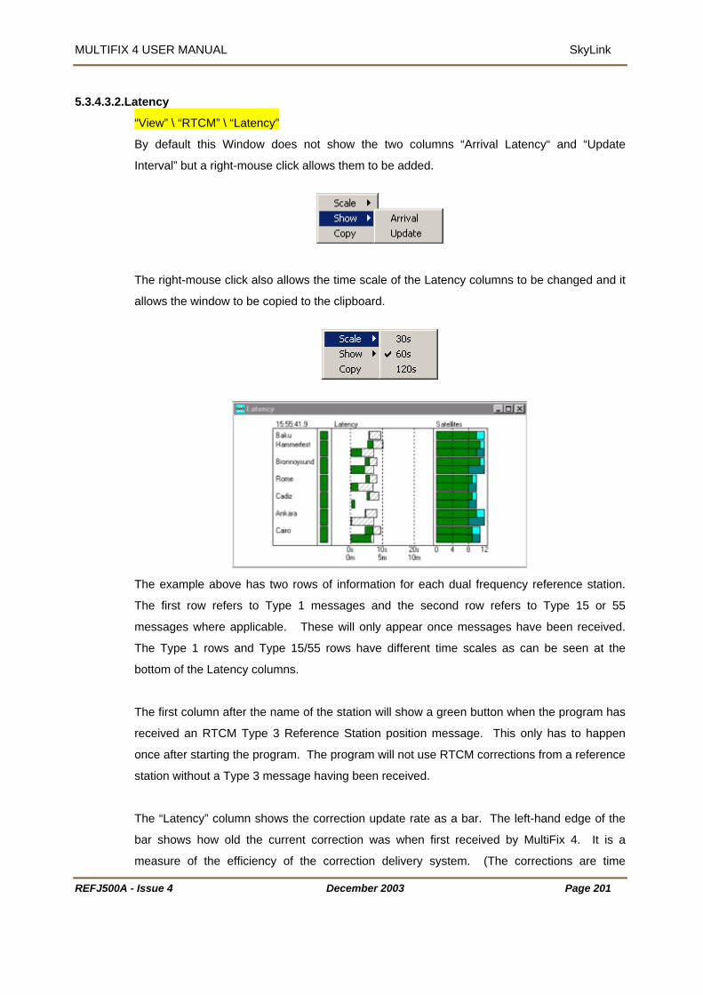
MULTIFIX 4 USER MANUAL SkyLink
REFJ500A - Issue 4 December 2003 Page 201
5.3.4.3.2.Latency
“View” \ “RTCM” \ “Latency”
By default this Window does not show the two columns “Arrival Latency“ and “Update
Interval” but a right-mouse click allows them to be added.
The right-mouse click also allows the time scale of the Latency columns to be changed and it
allows the window to be copied to the clipboard.
The example above has two rows of information for each dual frequency reference station.
The first row refers to Type 1 messages and the second row refers to Type 15 or 55
messages where applicable. These will only appear once messages have been received.
The Type 1 rows and Type 15/55 rows have different time scales as can be seen at the
bottom of the Latency columns.
The first column after the name of the station will show a green button when the program has
received an RTCM Type 3 Reference Station position message. This only has to happen
once after starting the program. The program will not use RTCM corrections from a reference
station without a Type 3 message having been received.
The “Latency” column shows the correction update rate as a bar. The left-hand edge of the
bar shows how old the current correction was when first received by MultiFix 4. It is a
measure of the efficiency of the correction delivery system. (The corrections are time

MULTIFIX 4 USER MANUAL SkyLink
REFJ500A - Issue 4 December 2003 Page 202
stamped with GPS time by the reference station, and as MultiFix 4 also has access to GPS
time the age of the corrections at the time of receipt is known). The right-hand side of the bar
advances until a new correction is received showing the age of the current correction. The
bar also shows a hatched area showing the update rate of the last correction received.
For Type 1 messages:
Bars will be green if the last correction was received in less than 25 seconds.
They will be yellow between 25 and 37½ Seconds.
They will be red if older than 37½ seconds. After 50 seconds the corrections from
that reference station will no longer be deemed usable.
For Type 15/55 messages:
The bars will be green if the last correction was received in less than 5 minutes.
They will be yellow if received between 5 minutes and 7½ minutes.
They will be red if older than 7½ minutes. Type 55 information is considered stale if it
is more than 10 minutes old.
The “Latency” panel has a negative area. Some GPS correction systems (not SkyFix) try to
predict corrections for a point of time in the future when a correction is to be used. If a fast
data transfer system is used the corrections can arrive with a time stamp earlier than current
time, in which case the bar will start in the negative portion of the panel.
The optional “Arrival Latency“ and “Update Interval” panels contain data extracted from the
“Latency” panel.
In “Arrival Latency” the right-hand end of the bar shows how old the current corrections were
when received by MultiFix 4.
In “Update Latency” the bar shows how long elapsed between the receipt of the current and
previous correction messages.
The “Satellites” column shows how many satellites (viable for use by MultiFix) can be seen at
each reference station.
The colour coding is: -
Green - correction data has been received for the expected satellite(s).
Yellow - the satellite(s) are unhealthy.
Dark blue – the satellite(s) is in the high scale factor mode, i.e. the resolution is
32cms as opposed to 2cms. This is usually caused by a rate value greater than
±0.256m/sec.

MULTIFIX 4 USER MANUAL SkyLink
REFJ500A - Issue 4 December 2003 Page 203
Light blue (Aqua) - no corrections have been received for one or more expected
satellites, i.e. it is missing.
Red - the satellite(s) has been disabled by the user in the SV Status dialogue.
(Without almanac information, the satellites table will show missing satellites. If there is no
GPS receiver from which to obtain time, the latency information may be incorrect).
5.3.4.3.3.Station
“View” \ “RTCM” \ “Station”
The window initially opens showing the first RTCM reference station. To have the window
show data for another station, right click on the window and select the station.
The top left table shows the time tag of the latest messages, the age of the corrections and
the percentage.
For Type 1 messages a percentage of 30 seconds.
For Type 2 messages a percentage of 300 seconds.
For Iono (Type 55 or Type 15) messages a percentage of 600 seconds.
Message (Type 16) a percentage of 600 seconds. When received the message will be
displayed at the top of the window and will remain for 10 minutes unless overwritten.
The Location shows the station position as received in the Type 3 message.
The lower table has various sub-sections.
“PRN” is the satellite number.

MULTIFIX 4 USER MANUAL SkyLink
REFJ500A - Issue 4 December 2003 Page 204
“Position” shows the satellites’ positions and if they are rising the elevation is tagged with a ^.
“Atmosphere” has: -
“Direct” is the ionospheric delay derived for the present moment from the dual
frequency information. (It will not be present if a single frequency reference station is
selected).
“Iono” is the ionospheric delay for time now from the Klobachar model
“Tropo” is the tropospheric delay for time now from the tropospheric model.
“Type 1” has: -
“Corrn.”, which is the current pseudo-range correction
“Rate”, which is the rate of change of the pseudo-range correction
“IODE”, which is the Issue of Data Ephemeris
“U”, which is the User Differential Range Error, (normally 0)
“SF” is flagged when the Correction Rate is greater then ±0.256 or when the
correction is >±660.
The “Type 2” table will usually only be seen during an Ephemeris change (every 2 hours),
when the mobile’s GPS receiver is using a different Issue of Ephemeris to the reference
station being viewed.
“Corrn”, which is the correction to the correction based on the difference in IODE.
“Rate”, which is the rate of change of the correction.
“IODE”, which is the Issue of Data Ephemeris number.
“Direct” contains the Ionospheric delay values and rates as transmitted in the Type 15 or 55
messages. (Without Type 15/55 information the section will be omitted).
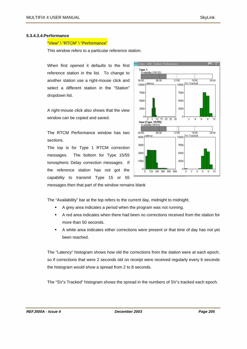
MULTIFIX 4 USER MANUAL SkyLink
REFJ500A - Issue 4 December 2003 Page 205
5.3.4.3.4.Performance
“View” \ “RTCM” \ “Performance”
This window refers to a particular reference station.
When first opened it defaults to the first
reference station in the list. To change to
another station use a right-mouse click and
select a different station in the “Station”
dropdown list.
A right-mouse click also shows that the view
window can be copied and saved.
The RTCM Performance window has two
sections.
The top is for Type 1 RTCM correction
messages. The bottom for Type 15/55
Ionospheric Delay correction messages. If
the reference station has not got the
capability to transmit Type 15 or 55
messages then that part of the window remains blank
The “Availability” bar at the top refers to the current day, midnight to midnight.
A grey area indicates a period when the program was not running.
A red area indicates when there had been no corrections received from the station for
more than 50 seconds.
A white area indicates either corrections were present or that time of day has not yet
been reached.
The “Latency” histogram shows how old the corrections from the station were at each epoch,
so if corrections that were 2 seconds old on receipt were received regularly every 6 seconds
the histogram would show a spread from 2 to 8 seconds.
The “SV’s Tracked” histogram shows the spread in the numbers of SV’s tracked each epoch.

MULTIFIX 4 USER MANUAL SkyLink
REFJ500A - Issue 4 December 2003 Page 206
The “Iono Type 15/55” tables at the bottom show the same information as above for those
message types. The permitted Type 15/55 messages are not considered stale until 600
seconds has elapsed rather than the 50 seconds for the Type 1 messages.
5.3.4.3.5.SkyFix Decoder
“View” \ “RTCM” \ “SkyFix Decoder”
Assuming the SkyFix Decoder option has been enabled and given an IO channel, see Section
5.3.2.3 on page 179, the output from the decoder can be viewed.
The decoder can output “TEST” data on port 4 only. The interval between updates occurs
every 1000 data blocks received and is proportional to the
satellite channel data rate.
This update rate may be between 2.5 and 6 minutes.
The BER or Bit Error Rate is typically between 5 and 7.
The Voltage is the signal strength voltage, <1 volt indicates poor signal level, >2 volts
indicates good signal level.
The Frequency Offset should be in the range ±2.50 kHz.

MULTIFIX 4 USER MANUAL SkyLink
REFJ500A - Issue 4 December 2003 Page 207
5.3.5. OPTIONS
LockColourHide Toolbar
Setup001- SkyLink File Config Action View Options Window Help
5.3.5.1. Lock
“Options” \ “Lock”
If the Lock option is chosen “File” and Config” are removed from the menu bar. Whilst locked,
“Options” \ “Lock” changes to “Options” \ “Unlock”. This reinstates “File” and Config”.
5.3.5.2. Colour
“Options” \ “Colour”
If different colour schemes are
required they can be set up here.
Ensure that a false impression is
not given when changing the
colour coding, in particular
relating to errors.
Some of the selections do not
affect all view windows.
• “Main”
“Background” and “Text” change the windows background and text colours.
“Neutral” is used in the Latency window to show period when update may be
expected.
“Link” is not currently used.
• “Error”.
Various windows have stages of error state, these colours relate to them.
“Good”, “Bad” and “Warning”.
• “Miscellaneous”
“Output” as seen in the IO status and IO Scroller windows.
“Missing” as seen in the Latency and Constellation windows.

MULTIFIX 4 USER MANUAL SkyLink
“Out of Range” as seen in the Latency and Constellation windows when a satellite is
ask.
5.3.5.3. Hid
below the m
e Tool Bar
“Options” \ “Hide Tool Bar”
This will hide the shortcut toolbar displayed at the top of the MultiFix screen.
When hidden the option will change to “show toolbar” which will return the toolbar to the
screen when selected.
REFJ500A - Issue 4 December 2003 Page 208

MULTIFIX 4 USER MANUAL SkyLink
REFJ500A - Issue 4 December 2003 Page 209
5.3.6. WINDOWS
TileClose All
1 RTCM 1 Out Unchanged - Scrolling IO2 RTCM 1 Out Type 55 to 15 - Scrolling IO3 RTCM 1 Out Correct Type 1 - Scrolling I4 RTCM 1 Out Crt Type 1 (Rev Kl) - Scrolling IO5 RTCM 1 Out Apply Diff Klbuchar - Scrolling IO6 RTCM 1 In - Scrolling IO7 IO Status8 Latency9 Cadiz - Diff. Station
Setup001- SkyLink File Config Action View Options Window Help
5.3.6.1. Tile
“Window” \ “Tile”
The tile command causes the application workspace to be reduced to the display area. The
windows that are not minimised are re-sized and fitted into the display area The minimised
windows are neatly stacked along the bottom of the screen.
5.3.6.2. Close All
“Window” \ “Close All”
The close all command does just that. All the windows irrespective of their status will be
closed. As there is no confirmation required, be careful not to use it in error.
5.3.6.3. The Open Windows
The “Window” drop down will also list all the windows currently open. Windows can be
overlain one on top of another and it can be difficult to locate an obscured window. Clicking
the window in the list causes the focus to shift to that window, the title bar is highlighted and it
will come on top of all the other windows. If there is an extended application workspace and
the selected window is off screen, while it will be the window with the focus the display area
will not move to show the window.
If there are more than 9 windows open the bottom line will be “More Windows…” If that is
selected a dialogue is opened listing all the windows. Highlight one of them and close the
dialogue.

MULTIFIX 4 USER MANUAL SkyLink
REFJ500A - Issue 4 December 2003 Page 210
5.3.7. HELP
DonglePerformance
Setup001- SkyLink File Config Action View Options Window Help
About
5.3.7.1. Dongle
“Help” \ “Dongle…” provides the information
stating
• which programs the DK2 is authorised to run
• the time limit of the dongle
• the amount of use the dongle has already had.
SkyLink does not require a dongle. If a dongle is
in the parallel port it will be interrogated as shown
opposite. If there is not one there a message will
be posted saying no dongle present.
5.3.7.2. Performance
“Help” \ “Performance”
The Performance window shows how the program is handling the data acquisition and
calculation process with the available
resources. The window does not take
into account other programs that are
running simultaneously.
The graphs will be green below 50%,
yellow between 50% and 75% and red
when above 75%.
It is important there is enough time for all the processes to be completed in an orderly fashion.
If there are too few resources the position solution may lag. The demand on the processor
can be reduced by accessing only the data from the RTCM reference stations used in the
computations, by having fewer computations and by closing windows.

MULTIFIX 4 USER MANUAL SkyLink
The performance information can also be seen in the bar at the bottom of the application
Time.
5.3.7.3. About
window next to the UTC
“Help” \ “About…” provides the version number and release date
REFJ500A - Issue 4 December 2003 Page 211

MULTIFIX 4 USER MANUAL Receiver Verify
6. RECEIVER VERIFY (RXV)
designed as an additional component to the core MultiFix 4
pplication and must be used in conjunction with MultiFix 4.
e PDS–Lite
pplication. RxV then combines all off the information into a single set of GPS pseudoranges
ith a
eliable stable and continuous GPS position even in the most difficult of situations.
signed in a modular fashion such that data is passed between modules as if
ver a computer network. As such RxV must be used with both MultiFix 4 and PDS 2000 in
While a single computer can be used for all three, the individual modules can also be run on
different computers provided there is networ nnection availa
R grams avail the Zero Suite and thi n relates
p e are some re ces in the manual to the other programs,
s
The text in this manual conforms to certain conventions
7. All com tons are shown bold and eted with square bracket K],
8. When a d key is represented, i bold and bracketed by than and
lesser than symbols e.g. <spacebar>.
9. Each d as a title. When the the text it is underline Edit GPS
Receive
10. Direct quotations from dialogues or e rol slots are shown in al text in
quotations, e.g. “IO Channel:”
6.1. INTRODUCTION
Receiver Verify, or RxV, is
a
RxV takes in Almanac, Ephemeris, Raw Code and Carrier measurements from multiple GPS
receivers. RxV also requires real-time antenna offset information from th
a
for a user-defined location. In this way, any blockage or interference in the GPS signals at an
individual antenna location can be identified and corrected for, providing the user w
r
RxV has been de
o
order to function correctly.
k interco ble.
xV is one of a series of pro able in s sectio
rimarily to RxV although ther feren
uch as MultiFix 4.
mand but brack s e.g. [O
keyboar t is shown greater
ialogue h name is in d e.g.
r.
dit cont norm
REFJ500A - Issue 4 December 2003 Page 212

MULTIFIX 4 USER MANUAL Receiver Verify
6.1.1. RXV APPLICATIONS
hore vessels suffer unavoidable blockage of GPS satellites. Vessels such as Jack
p drilling rigs, lift boats and constructions barges have overhead obstructions, sometimes
example below a crane barge has four available locations for GPS
ntennas.
diagram.
Traditionally this would be avoided by raising the antennas on a mast above the level of the
stowed cranes.
Many offs
U
dynamic such as a crane, resulting in no suitable location for the GPS antenna. This can
have serious implications on many projects, often during the most critical phase of the
operation. In the
a
The two heavy lift cranes cause some obstruction, even when stowed. This can be in the
form of direct blockage or as multipath and is marked in red on the
REFJ500A - Issue 4 December 2003 Page 213

MULTIFIX 4 USER MANUAL Receiver Verify
When the cranes are operational the masking situation changes. The cranes will be lifted from
location and rise far above the GPS antennas.
xV allows the user to combine the
nobstructed views from each antenna to produce a “virtual GPS antenna” at any selected
location. In this way, stable positioning can be maintained throughout any operation, even if
ere is masking of the individual antennas.
6.1.2. Operational Theory
ranges are called Pseudorange as they are not direct measurements of distance but
erived from the travel time of the signals form the GPS.
orientation of the GPS antenna is known, the range can be
ansposed to another location over a short range. RxV combines each set of pseudorange in
d. The remaining pseudoranges are then combined to
erive a set of pseudoranges for a “virtual” antenna at the common location.
their normal
It should be noted that in both of the examples that, between them, the array of GPS
antennas has an unobstructed view in all directions. R
u
th
A GPS position is derived by combining the individual ranges from each GPS satellite. These
satellite
d
If the relative location and
tr
this way by transposing the observations from each antenna to a common location. The
resultant redundancy can be used to check if any of the transposed pseudoranges are
obviously erroneous, and if so, remove
d
REFJ500A - Issue 4 December 2003 Page 214

MULTIFIX 4 USER MANUAL Receiver Verify
6.2. CONFIGURATION
V
Figure 13 Example Interconnection with four GPS Receivers and soccer software
In the above example, four separate GPS receivers are being used in various locations
essages for transfer over the LAN.
most suitable for the
ssel.
he PDS-Lite module requires inputs from both a pitch and roll sensor and a gyro. The
in order to provide a DGPS solution.
around the vessel. The GPS measurements are transferred back to the RxV module via either
a Local Area Network (LAN) or standard RS-232. If the data is to be transferred over a LAN
then another zero application, Soccer, can be used to convert the serial data output from the
GPS receiver into TCP/IP m
It is possible to transfer the data using a number of techniques, including radio modems or
fibre optic cables. The communications structure is based on the system
ve
T
MultiFix module will also require RTCM corrections, such as those from a 90938 SkyFix
decoder,
REFJ500A - Issue 4 December 2003 Page 215
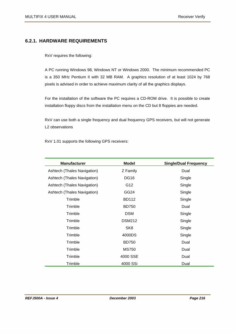
MULTIFIX 4 USER MANUAL Receiver Verify
6.2.1. HARDWARE REQUIREMENTS
RxV requires the following:
A PC running Windows 98, Windows NT or Windows 2000. The minimum recommended PC
is a 350 MHz Pentium II with 32 MB RAM. A graphics resolution of at least 1024 by 768
ixels is advised in order to achieve maximum clarity of all the graphics displays.
For the installation of the software the PC requires a CD-ROM drive. It is possible to create
installation floppy discs from the installation menu on the CD but 8 floppies are needed.
RxV can use both a single frequency and dual frequency GPS receivers, but will not generate
L2 observations
RxV 1.01 supports the following GPS receivers:
Manufacturer Model Single/Dual Frequency
p
Ashtech (Thales Navigation) Z Family Dual
Ashtech (Thales Navigation) DG16 Single
Ashtech (Thales Navigation) G12 Single
Ashtech (Thales Navigation) GG24 Single
Trimble BD112 Single
Trimble BD750 Dual
Trimble DSM Single
Trimble DSM212 Single
Trimble SK8 Single
Trimble 4000DS Single
Trimble BD750 Dual
Trimble MS750 Dual
Trimble 4000 SSE Dual
Trimble 4000 SSi Dual
REFJ500A - Issue 4 December 2003 Page 216

MULTIFIX 4 USER MANUAL Receiver Verify
REFJ500A - Issue 4 December 2003 Page 217
6.2.2. COMMUNICATIONS NETWORK
The nature of MultiFix RxV requires the GPS receivers to be distributed widely about the
vessel.
Running excessive antenna cables is not usually a viable option due to the potential distances
involved. As an alternative, the data from each receiver can be transmitted back over a serial
connection or LAN.
The simplest solution is to run serial cables from each receiver, however to operate over
longer distances an RS232 to RS422 adapter would be needed.
For installations in remote or inaccessible locations a radio telemetry system, such as the
Thales TracsCOM can be used.
Alternatively a Local Area Network (LAN) can be used. Soccer is used to convert RS232
communications from the GPS Rx to a TCP/IP socket (See Section 7). The data can then be
transmitted over a standard Ethernet network connection. Where space is limited, small serial
to Ethernet converters are also available.
The existing ships IT infrastructure can be used (if available) or standard PC networking
components can be used, including wireless networking products.

MULTIFIX 4 USER MANUAL Receiver Verify
6.2.3. RXV FILES After installation and after a program run, RxV will have created / stored several files in the
folder selected by the operator for the configuration file.
The *.rxv is the core RxV configuration file and is stored in XML format.
rxv_PST is the Persistence file; it is the number, type, position and contents of windows in the
RAF is a GPS almanac. This will be updated as the almanac changes and when the
s saved.
e almanac changes and
hen the configuration file is saved. The XAL file is stored as in an XML format for export to
then ALL the above files should be returned as well.
application workspace when a configuration file is saved. It is written when the program is
exited.
rxv_
configuration file i
rxv_XAL file is another GPS almanac. This will be updated as th
w
other applications, such as GeoSky 2.
If log files are to be returned for analysis,
REFJ500A - Issue 4 December 2003 Page 218
MULTIFIX 4 USER MANUAL Receiver Verify
UN RXV
grams” \ “MultiFix 4 Vx.xx” and click “Receiver Verify”.
6.2.5. MU
In order to derive a position from the RxV output data MultiFix 4 must be used.
connection must be established between the two software modules. This can be
through a serial port. If a serial port is used a high baud rate should be
6.2.6. IN
tch and Roll sensor information and offset measurements are handled by the PDS 2000 Lite
is then provided as a 3D model of the relative physical relationship of the GPS
of the vessel and the motion of
he module therefore requires a position input as well as gyrocompass and motion sensor
The input is then entered into Receiver Verify under Rx Position Input see section 0 for more
details.
6.2.4. TO R
RxV can be opened a variety of ways.
Use Windows Explorer to display the contents of the folder containing the RxV program files
and then double-clicking the “Receiver verify” application icon.
Select “Start” \ “Pro
LTIFIX CONFIGURATION
A data
either via sockets or
selected (38400 at least).
MultiFix is then configured as per a normal GPS receiver by selecting “Receiver Verify” as the
GPS Rx. type.
TERFACING TO PDS 2000 LITE
Pi
module. Data
antenna onboard based on their known offsets, the heading
the vessel (pitch and roll).
T
data and outputs the model as a formatted message to Receiver Verify.
Please refer to the PDS manual for details of configuring PDS 2000 Lite.
REFJ500A - Issue 4 December 2003 Page 219

MULTIFIX 4 USER MANUAL Receiver Verify
6.3. REAL TIME OPERATION
Config Logger Action View Options Window HelpFile New Open… Save Save As… Exit
Setup001 - Receiver Verify MultiFix3
New Open… Save Save As… Exit
Setup001 - Receiver Verify MultiFix3 Setup001 - Receiver Verify MultiFix
File File
Logger Action View Options Window Help
IO GPS Rx Rx Position input.. CalculationReceiver Output..
Comm…Socket…
Setup001 - Receiver Verify MultiFix3
New…
1 <name> Edit…Delete
Receivers…Parameters…
File Config IO GPS Rx Rx Position input..
tput.. CalculationReceiver Ou
Comm…Socket…
Setup001 - Receiver Verify MultiFix
New…
1 <name> Edit…Delete
Receivers…Parameters…
File Config
Receiver Verify
Action View Options Window Help
Edit Start Pause Resume Stop View Logfile Status
Setup001 - MultiFix3 File Config Logger
Edit Start Pause Resume Stop View Logfile Status
Edit Start Pause Resume Stop View Logfile Status
Setup001 - MultiFix
File Config Logger
Receiver Verify
View Options Window Help
Restart Sockets
Setup001 - MultiFix3 Setup001 - MultiFix
File Config Logger Action
REFJ500A - Issue 4 December 2003 Page 220

MULTIFIX 4 USER MANUAL Receiver Verify
REFJ500A - Issue 4 December 2003 Page 221
Options Window HelpFile Config Logger Action
GPSStatus
Setup001 - Receiver Verify MultiFix3
StatusSocketsDatagramsScroller
SynchClockAlmanacEphemerisConstellation
Rx StatusRelative OffsetsClock DifferencesClock differences PRNClock Differences Rx
IO
Memory Use
View
File Config Logger Action View
Receiver Verify
LockColour
Setup001 - MultiFix3 MultiFix
Options Window Help
Hide Toolbar
File Config Logger Action View Options
Setup001 - Receiver Verify MultiFix3
Help
TileClose All
1 IO Status2 Almanac3 Constellation4 Ephemeris
Setup001 - Receiver Verify MultiFix3
Window Help
File Config Logger Action View
Dongle...PerformanceAbout...
Setup001 - Receiver Verify MultiFix3 File Options Window
Setup001 - Receiver Verify Help

MULTIFIX 4 USER MANUAL Receiver Verify
6.3.1. FIL
E
Config Logger Action View Options Window HelpFile New Open… Save Save As… Exit
Setup001 - Receiver Verify MultiFix3
New Open… Save Save As… Exit
Setup001 - Receiver Verify MultiFix3 Setup001 - Receiver Verify MultiFix
File File
6.3.1.1. New
“File” \ “New…”
o start a new RxV configuration select this option.
eware, starting a new configuration will close the existing configuration and assuming the
l cease real time operation. A confirmation box will
confirmation before closing the previous configuration. If the configuration has not
een saved the confirmation box will prompt the user to do so.
recently used configuration files. Clicking on one
e chosen configuration.
6.3.1.2. Op
T
B
program is already up and running, it wil
request
b
At the bottom of the “File” menu is a list of
of these files opens up th
en
“File” \ “Open…”
When opened the program does not know
previously prepared configu
which configuration file to open. Assuming a
ration exists, use this facility to select it.
pened that are not compatible with the
ersion of RxV that is currently being
version is the same they can be used even though
The configuration files have program
name and version identifiers in a file
header. They also have a configuration
file version number. The program will
not allow configuration files to be
o
v
run. However if the configuration file
created by a different program version.
REFJ500A - Issue 4 December 2003 Page 222
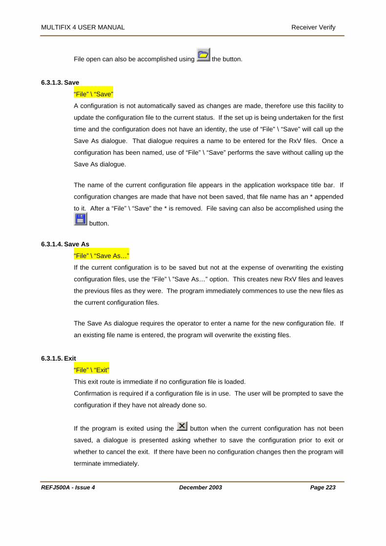
MULTIFIX 4 USER MANUAL Receiver Verify
File open can also be accomplished using the button.
ve 6.3.1.3. Sa
“File” \ “Save”
A configuration is not automatically saved as changes are made, therefore use this facility to
urrent status. If the set up is being undertaken for the first
me and the configuration does not have an identity, the use of “File” \ “Save” will call up the
tered for the RxV files. Once a
named, use of “File” \ “Save” performs the save without calling up the
ave As dialogue.
n workspace title bar. If
onfiguration changes are made that have not been saved, that file name has an * appended
oved. File saving can also be accomplished using the
update the configuration file to the c
ti
Save As dialogue. That dialogue requires a name to be en
configuration has been
S
The name of the current configuration file appears in the applicatio
c
to it. After a “File” \ “Save” the * is rem
button.
ve As 6.3.1.4. Sa
“File” \ “Save As…”
If the current configuration is to be saved but not at the expense of overwriting the existing
onfiguration files, use the “File” \ ”Save As…” option. This creates new RxV files and leaves
commences to use the new files as
he Save As dialogue requires the operator to enter a name for the new configuration file. If
an existing file name is entered, the program will overwrite the existing files.
6.3.1.5. Exit
c
the previous files as they were. The program immediately
the current configuration files.
T
“File” \ “Exit”
This exit route is immediate if no configuration file is loaded.
Confirmation is required if a configuration file is in use. The user will be prompted to save the
configuration if they have not already done so.
If the program is exited using the button when the current configuration has not been
saved, a dialogue is presented asking whether to save the configuration prior to exit or
whether to cancel the exit. If there have been no configuration changes then the program will
terminate immediately.
REFJ500A - Issue 4 December 2003 Page 223

MULTIFIX 4 USER MANUAL Receiver Verify
6.3.2. CONFIGURE
Logger Action View Options Window Help
IO GPS Rx Rx Position input.. CalculationReceiver Output..
Comm…
Setup001 - Receiver Verify
Socket…
MultiFix3
New…
1 <name> Edit…Delete
Receivers…Parameters…
File Config IO GPS Rx Rx Position input.. CalculationReceiver Output..
Comm…
Setup001 - Receiver Verify
Socket…
MultiFix
New…
1 <name> Edit…Delete
Receivers…Parameters…
File Config
6.3.2.1. IO
“Config” \ “IO”
omm 6.3.2.1.1.C
“Config” \ “IO” \ “Comm…”
” / “IO Config” applet needed to
ter has available (see section 3.4 on
age 13). The parameters selected there determine the dialogue box that is presented when
pens another dialogue box for
rt parameter settings.
ata Bits, Parity and
Earlier it was explained that the “Programs” / “MultiFix 4 Vx.xx
be run after installation to define what ports the compu
p
“Config” \ “IO” \ “Comm…” is selected.
Highlight one of the ports to be used and click [Edit]. This o
setting the po
Click the [Enable] button to activate the port
and set the Baud Rate, D
Stop Bits.
REFJ500A - Issue 4 December 2003 Page 224

MULTIFIX 4 USER MANUAL Receiver Verify
REFJ500A - Issue 4 December 2003 Page 225
6.3.2.1.2.Sockets
“Config” \ “IO” \ “Socket…”
To be able to distribute and receive data over a network via sockets assumes each computer
has Transmission Control Protocol / Internet Protocol (TCP/IP) installed. Sockets have the
advantage over COM ports in that two or more programs can access the same data.
Sockets can transfer data between programs running on different computers or between two
or more programs running on the same computer. (If a standalone (non-networked) computer
running Windows NT is used and the data is to be shared between multiple programs running
on that PC then the MS Loopback Adapter network adapter must be installed).
The TCP/IP protocol is a family of protocols that allow Internet data communication. Included
in that family are two transport layer protocols, the Transport Control Protocol (TCP) and the
User Datagram Protocol (UDP).
The Transport Control Protocol establishes sessions between a Server and however many
Clients that are accessing that Server. There is continual presence checking and
acknowledging between each Server/Client pairs with messages always received in the order
they were issued. A Server does not have control of the number of Clients that access the
socket on which data is being presented. (It is often perceived that the Server provides data
and the Client receives data, but once the connection is established the link is two-way).
• The User Datagram Protocol does not have the end-to-end checking overhead of the
TCP. Instead packets of data are simply issued to the Internet in either broadcast mode,
where any networked computer on the LAN can receive them, or in addressed mode
where the data packets have headers specifying the addressees for whom the packets
are intended. There is no guarantee with this protocol that the messages will arrive in the
order they were issued. When setting up “Ribbons” to output datagrams a time interval
can be specified to prevent data becoming corrupted, see section on “Ribbons” 7.3.2.2.
Broadcast datagrams cannot pass routers linking Local Area Networks (LAN) unless
specifically configured.
For most situations where Local Area Networks are involved Server / Client TCP sockets are
the best choice Internet transport protocols.

MULTIFIX 4 USER MANUAL Receiver Verify
REFJ500A - Issue 4 December 2003 Page 226
6.3.2.1.2.1.The RxV Computer as a TCP Client
For a Client to make contact with a Server, the operator must know the IP address (or the
network identification name - see below) of the Server computer and the port number the
Server is outputting the required data on.
First, in the “PC Names” table click
[New].
There are two possible ways of
defining the server PC.
If the numerical IP address is known,
enter a PC name in “Name:” and the IP
address in “Address:” and click
[Resolve>>]. Click [OK].
If the IP address is not known but the computer’s network identification name is, and if all
computers involved are aware of local naming services (WINS / DNS), then type in the
computer’s name in the “Address:” slot and click [Resolve>>]. Once the computer is found,
its IP address will appear as shown. If required, use [>>Literal] to transfer the name and
address to their named slots. Click [OK].
It is normal in a network for computers
to be allocated new IP addresses
when the PC is restarted. If the Client
PC has a numerical entry for the

MULTIFIX 4 USER MANUAL Receiver Verify
address and the Server’s address has changed, it will not be able to re-locate it. If the Client
of the Server PC in the address slot, it will automatically search to re-locate
ming it is found, the Client PC will obtain the Server PC’s
elect the ”PC
lt name if required.
6.3.2.1.2.2.The RxV Computer as a TCP Server
If the RxV computer is to be a server then there is no
need to add the Soccer computer to the PC table; the
program already knows the computer’s IP address. This
can be seen in the window called up by “View” \
“Sockets”, see 6.3.5.1.2 on page 241.
In the “Sockets” table click [New]. Give the socket a
name and enter the Port number that the data will be
output on. Click [OK] to exit.
PC has the name
the Server PC by name. Assu
current address.
In the “Sockets” table click [New].
Now check the “Client” radio button and s
Name:” of the server.
Enter the number of the port on which the Server PC is
presenting the data. Change the socket’s defau
REFJ500A - Issue 4 December 2003 Page 227
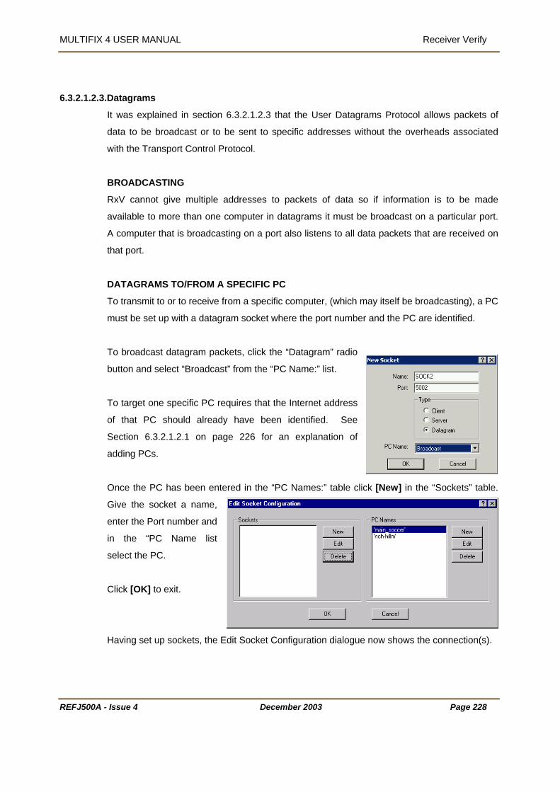
MULTIFIX 4 USER MANUAL Receiver Verify
6.3.2.1.2.3.Datagrams
tion 6.3.2.1.2.3 that the User Datagrams Protocol allows packets of
ata to be broadcast or to be sent to specific addresses without the overheads associated
ransport Control Protocol.
ultiple addresses to packets of data so if information is to be made
vailable to more than one computer in datagrams it must be broadcast on a particular port.
a port also listens to all data packets that are received on
IC PC
pecific computer, (which may itself be broadcasting), a PC
with a datagram socket where the port number and the PC are identified.
agram” radio
utton and select “Broadcast” from the “PC Name:” list.
planation of
nce the PC has been entered in the “PC Names:” table click [New] in the “Sockets” table.
elect the PC.
Socket Configuration dialogue now shows the connection(s).
It was explained in sec
d
with the T
BROADCASTING
RxV cannot give m
a
A computer that is broadcasting on
that port.
DATAGRAMS TO/FROM A SPECIF
To transmit to or to receive from a s
must be set up
To broadcast datagram packets, click the “Dat
b
To target one specific PC requires that the Internet address
of that PC should already have been identified. See
Section 6.3.2.1.2.1 on page 226 for an ex
adding PCs.
O
Give the socket a name,
enter the Port number and
in the “PC Name list
s
Click [OK] to exit.
Having set up sockets, the Edit
REFJ500A - Issue 4 December 2003 Page 228

MULTIFIX 4 USER MANUAL Receiver Verify
REFJ500A - Issue 4 December 2003 Page 229
6.3.2.2. GPS Receiver
“Config” \ “GPS Receiver”
6.3.2.2.1.New Receiver
“Config” \ “GPS Receiver” \ “New…”
This calls up the “New GPS Receiver” dialogue
shown opposite.
It is important that each receiver is given a relevant
name. As with other name labels, the program
does not use it for receiver recognition purposes
However all of the graphical displays will use the
given name. It is recommended that the physical
location of the antenna is used for the name. E.g.
Helideck or starboard bow etc..
In the “Type:” slot, select the receiver that RxV is to
use.
There are various possible selections.
• Z Family (Ashtech)* are dual frequency receivers.
• DG16 (Ashtech) )* is a single frequency receiver
• G12 (Ashtech) )* is a single frequency receiver
• GG24 (Ashtech) * is a single frequency receiver and is fitted in the Fugro 90964 units
• 4000 Series (Trimble) refers to either a single frequency 4000DS or a dual frequency
SSE/SSI
• MS750 (Trimble) is a dual frequency receiver
• BD750 (Trimble) is a dual frequency receiver
• BD112 (Trimble)* is a single frequency receiver board fitted to the 90938/F112 SkyFix
decoder.
• DSM212 (Trimble)* is a single frequency receiver.
• DSM (Trimble)* is a single frequency receiver board fitted to 90938/M SkyFix decoder.
• SK8 (Trimble)* is a single frequency receiver board, but not recommended for offshore
work. It has not been tested for full operation.
• Millennium (NovAtel) is a dual frequency receiver
MULTIFIX 4 USER MANUAL Receiver Verify
REFJ500A - Issue 4 December 2003 Page 230
• Receiver Server is used when the data is not live from an external receiver but is taken
from raw data log files.
• Receiver Verify is used for interfacing to the Receiver Verify (RxV) Module.
• Receiver Server is used when the data is not live from an external receiver but is taken
from another zero application. RxV outputs Receiver Server style data to MultiFix 4 using
the Receiver Verify format..
Please note – Even if a dual frequency receiver is selected, the system will only operate in a
single frequency mode.
In the “IO Channel:” edit control slot, select the receiver’s port.
The Ancillary Receiver option is used for synchronising GPS measurements over a data link.
It is not used in the current version of RxV.
Note, even though it possible to use dual frequency receivers in RxV, it is not possible to
generate a dual frequency measurement sets for the virtual antenna.
The receivers should be configured as per the MultiFix 4 section and may require third party
software to configure them.
6.3.2.2.2.Editing and Deleting
“Config” \ GPS Receiver” \ “<name>” \ “Edit…” or “Delete”
With GPS Receiver(s) now defined, when “Config” \ “GPS Receiver” is selected, the name (or
names) given to the GPS Receiver(s) now appears in the sub-menu below the “New…” menu
item.
If the set up requires editing, highlight the name of the source and then select the “Edit…”
option.
If the GPS Receiver is no longer in use, again use “Config” \ “GPS” \ “<name>” and select
“Delete”. You will be asked to confirm or cancel the deletion. Be aware that an inappropriate
deletion could impact severely on the normal operation of the program.

MULTIFIX 4 USER MANUAL Receiver Verify
6.3.2.3. Rx Position Input
“Config” \ “Rx Position Input…”
This calls up the “Receiver Position Input”
dialogue.
This is used to define the source of the
real-time antenna offsets.
The PDS software application will provide
ontinuous updates on the relative
ositions of each physical GPS antenna, based on measurements from the gyro and pitch/roll
c
p
sensors. For static applications and training purposes, the antenna offsets can be entered
using a file. See Appendix C for more details.
REFJ500A - Issue 4 December 2003 Page 231
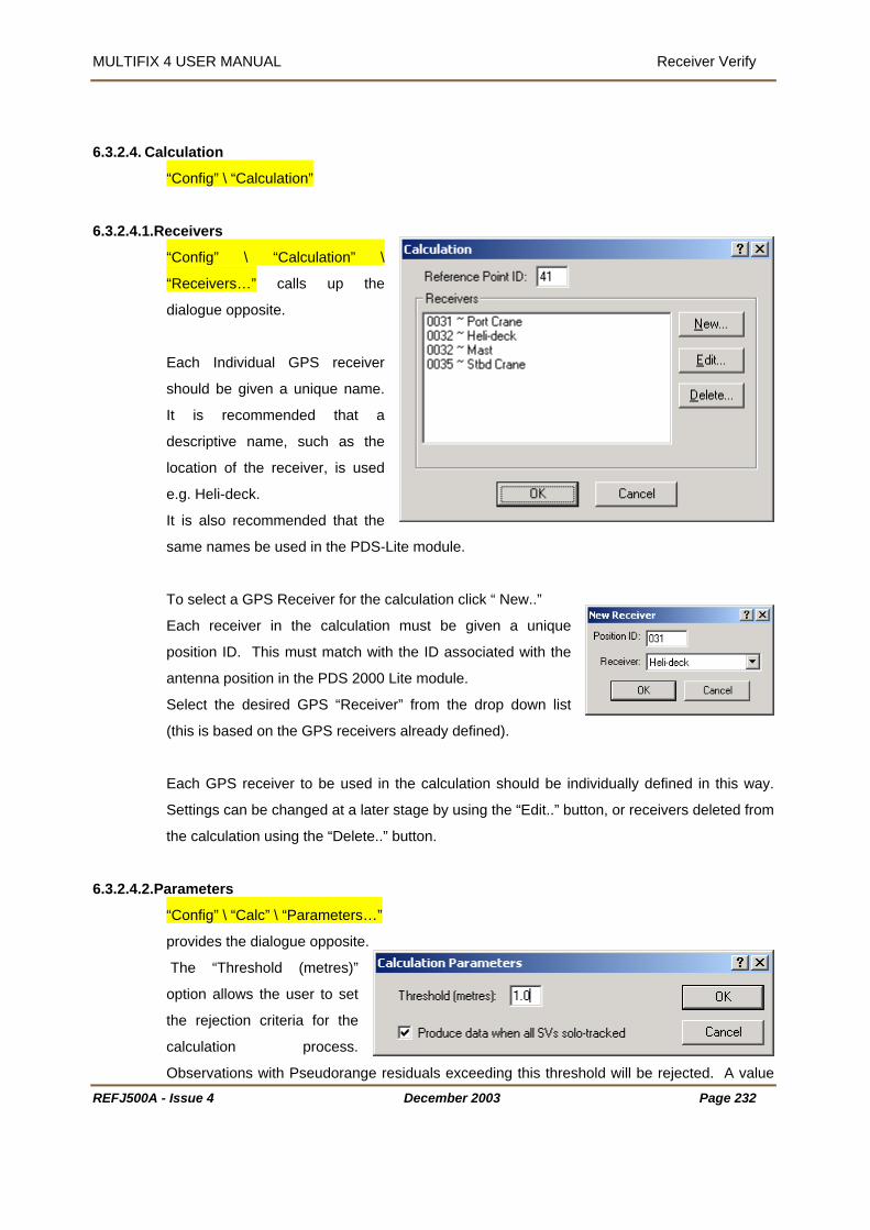
MULTIFIX 4 USER MANUAL Receiver Verify
6.3.2.4. Calculation
“Config” \ “Calculation”
6.3.2.4.1.R
eceivers
“Config” \ “Calculation” \
“Receivers…” calls up the
dialogue opposite.
er
.
is recommended that a
r, is used
.g. Heli-deck.
ame names be used in the PDS-Lite module.
o select a GPS Receiver for the calculation click “ New..”
osition ID. This must match with the ID associated with the
6.3.2.4.2.P
Each Individual GPS receiv
should be given a unique name
It
descriptive name, such as the
location of the receive
e
It is also recommended that the
s
T
Each receiver in the calculation must be given a unique
p
antenna position in the PDS 2000 Lite module.
Select the desired GPS “Receiver” from the drop down list
(this is based on the GPS receivers already defined).
Each GPS receiver to be used in the calculation should be individually defined in this way.
Settings can be changed at a later stage by using the “Edit..” button, or receivers deleted from
the calculation using the “Delete..” button.
arameters
“Config” \ “Calc” \ “Parameters…”
provides the dialogue opposite.
set
the rejection criteria for the
calculation process.
Observations with Pseudorange residuals exceeding this threshold will be rejected. A value
The “Threshold (metres)”
option allows the user to
REFJ500A - Issue 4 December 2003 Page 232

MULTIFIX 4 USER MANUAL Receiver Verify
of 2.5m is recommended.
duce data when all SVs solo-tracked” option allows the user to force the software to
continue providing data for each satellite, even if it tracked by only one of the GPS receivers.
This means that no independent checks can be performed on the collected data.
Clicking [OK] exits the dialogue and causes the calculation to commence.
The “Pro
REFJ500A - Issue 4 December 2003 Page 233

MULTIFIX 4 USER MANUAL Receiver Verify
r Output 6.3.2.5. Receive
“Config” \ “Receiver Output…”
The result of the calculation process is a data set created for a virtual GPS receiver.
It is necessary to define the output channel
newly created GPS data.
The data can only be used in MultiFix 3 (Ver 1.30 or
later) and MultiFix 4. It is normally output on a socket
but can be sent out on a serial port.
Note that if the data is to be sent out over a serial port a high baud rate should be used
(38400 or more).
for this
REFJ500A - Issue 4 December 2003 Page 234
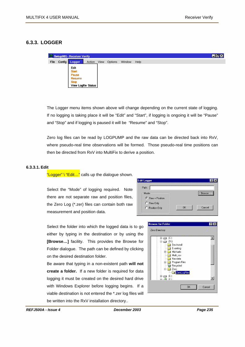
MULTIFIX 4 USER MANUAL Receiver Verify
6.3.3. LOGGER
Receiver Verify Action View Options Window Help
Edit Start Pause Resume Stop View Logfile Status
Setup001 - MultiFix3 File Config Logger
Edit Start Pause Resume Stop View Logfile Status
Edit Start Pause Resume Stop View Logfile Status
Setup001 - MultiFix
File Config Logger
The Logger menu items shown above will change depending on the current state of logging.
If no logging is taking place it will be “Edit” and “Start”, if logging is ongoing it will be “Pause”
and “Stop” and if logging is paused it will be “Resume” and “Stop”.
Zero log files can be read by LOGPUMP and the raw data can be directed back into RxV,
al time positions can
then be directed from RxV into MultiFix to derive a position.
6.3.3.1. Ed
where pseudo-real time observations will be formed. Those pseudo-re
it
“Logger” \ “Edit…” calls up the dialogue shown.
Select the “Mode” of logging required. Note
there are not separate raw
and position files,
the Zero Log (*.zer) files can contain both raw
measurement and position data.
Select the folder into which the logged data is to go
either by typing in the destination or by using the
[Browse…] facility. This provides the Browse for
Folder dialogue. The path can be defined by clicking
on the desired destination folder.
Be aware that typing in a non-existent path will not
create a folder. If a new folder is required for data
logging it must be created on the desired hard drive
with Windows Explorer before logging begins. If a
viable destination is not entered the *.zer log files will
be written into the RxV installation directory..
REFJ500A - Issue 4 December 2003 Page 235
MULTIFIX 4 USER MANUAL Receiver Verify
th and mode of logging have been selected click [OK]
.g.
61-1114, was started at 11:14 UTC on J-day 061.
automatically close and a new one will be
6.3.3.2. Sta
When the pa
The logging files names are based on the Julian day and time at the time of opening, e
0
When a file reaches 1.4 Mbytes in size it will
created.
rting, Stopping and Pausing
“Logger” \ “Start” is a command.
This will start the logging process. When data is
to “Pause” and “Stop”.
being logged the menu options will change
me” or “Stop” are selected.
top” will close the current log file and stop the logging process.
_lsd). It is written into the
so that LOGPUMP can be set
p correctly for the output of data as it contains the unique logging Ids for each of the
lculation status information.
-started the existing file is
tween one log session and
er log files to which it relates. Do not make
configuration changes while logging is on going.
When being archived or when being forwarded for replay analysis, the Schedule file should
be kept with the log files.
“Pause” will arrest the logging process until “Resu
“Resume” will restart logging into the existing file.
“S
When logging is started a Logging Schedule file is created (*.RxV
same folder as the RxV configuration files. This file is needed
u
receivers. The schedule contains the RxV version number and ca
There is only one file so if logging is stopped and then re
overwritten. If there have been configuration changes made be
subsequent log sessions, the Logging Schedule file will only be relevant for the later sessions.
Therefore, if changes are to be made after logging is stopped, use Explorer to make a copy of
the Schedule file and keep a note of the *.z
REFJ500A - Issue 4 December 2003 Page 236
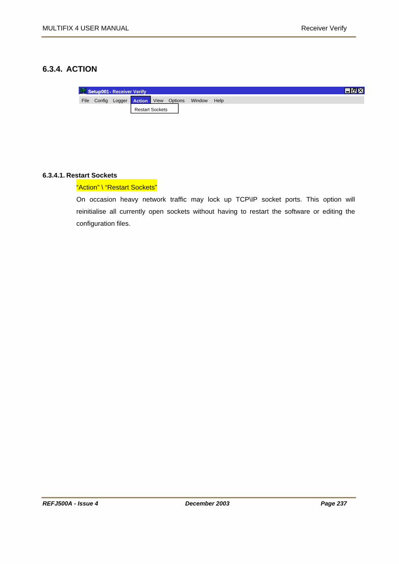
MULTIFIX 4 USER MANUAL Receiver Verify
6.3.4. ACTION
Receiver Verify
View Options Window Help
Restart Sockets
Setup001 - MultiFix3 Setup001 - MultiFix
File Config Logger Action
6.3.4.1. Re
start Sockets
“Action” \ “Restart Sockets”
socket ports. This option will
initialise all currently open sockets without having to restart the software or editing the
n files.
On occasion heavy network traffic may lock up TCP\IP
re
configuratio
REFJ500A - Issue 4 December 2003 Page 237
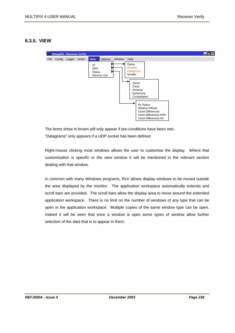
MULTIFIX 4 USER MANUAL Receiver Verify
6.3.5. VIEW
Options Window HelpFile Config Logger Action
GPSStatus
Setup001 - Receiver Verify MultiFix3
StatusSocketsDatagramsScroller
SynchClockAlmanacEphemerisConstellation
Rx StatusRelative OffsetsClock DifferencesClock differences PRNClock Differences Rx
IO
Memory Use
View
The items show in brown will only appear if pre-conditions have been met.
windows allows the user to customise the display. Where that
ustomisation is specific to the view window it will be mentioned in the relevant section
s to be moved outside
e area displayed by the monitor. The application workspace automatically extends and
ow further
election of the data that is to appear in them.
“Datagrams” only appears if a UDP socket has been defined
Right-mouse clicking most
c
dealing with that window.
In common with many Windows programs, RxV allows display window
th
scroll bars are provided. The scroll bars allow the display area to move around the extended
application workspace. There is no limit on the number of windows of any type that can be
open in the application workspace. Multiple copies of the same window type can be open.
Indeed it will be seen that once a window is open some types of window all
s
REFJ500A - Issue 4 December 2003 Page 238
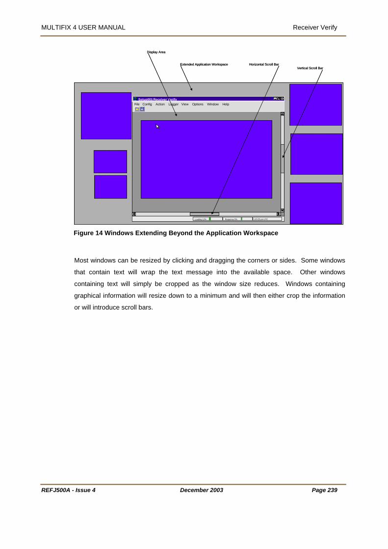
MULTIFIX 4 USER MANUAL Receiver Verify
Display Area
Extended Application Workspace Horizontal Scroll Bar Vertical Scroll Bar
Setup001- Receiver VerifyFile Config Logger View Options Window Help
MultiFix3
Loading 12% Response 5% 1:03:25 pm UTC
Display Area
Extended Application Workspace Horizontal Scroll Bar Vertical Scroll Bar
Setup001- Receiver VerifyFile Config Action Logger View Options Window Help
Loading 12% Response 5% 1:03:25 pm UTC
igure 14 Windows Extending Beyond the Application Workspace
sized by clicking and dragging the corners or sides. Some windows
ing text will simply be cropped as the window size reduces. Windows containing
graphical information will resize down to a minimum and will then either crop the information
or will introduce scroll bars.
F
Most windows can be re
that contain text will wrap the text message into the available space. Other windows
contain
REFJ500A - Issue 4 December 2003 Page 239

MULTIFIX 4 USER MANUAL Receiver Verify
6.3.5.1. Input / Output
“View” \ “IO”
There are three sub-menus and each will call a indow to the RxV application workspace.
6.3.5.1.1.S
ates when there is port
ctivity.
By default the window will contain the ports
RxV knows to exist. The “None” I/O Channel
at the top followed by streamed socket
hannels, datagram sockets and then the
OM and Digiboard channels.
(When setting up Input / Output channels
there is the option to select a dummy channel
“None”. If selected the blue vertical bars would be seen progressing across the None Output
box.)
A right-mouse click calls up the [Channel] button. When this is
clicked the IO Status dialogue is presented. This allows
channels to be selected or deselected from the status window.
In the IO Status window the latest time is in the centre between
the Input and Output columns. Each box indicates when data
has been input or output, over the last 5 seconds, on that port
by scrolling vertical bars from the centre to the outside edges of the window. The box re-
scales such that the greatest data rate over the last 5 seconds is full scale. The current bit
rate is shown opposite the I/O channel name.
w
tatus
This window indic
a
is
c
C
REFJ500A - Issue 4 December 2003 Page 240

MULTIFIX 4 USER MANUAL Receiver Verify
REFJ500A - Issue 4 December 2003 Page 241
6.3.5.1.2.Sockets
“View” \ “IO” \ “Sockets””
A client socket can have three states,
Idle, Connecting and Connected.
Idle and Connecting will alternate while connection is trying to
be established. There will also be a time countdown to the
next attempt to make contact.
A server socket can have two states,
Idle and Listening.
The Idle status is almost immediately replaced by Listening.
6.3.5.1.3.Datagrams
“View” \ “IO” \ “Datagrams”
The Datagram Status window lists all Datagrams in use. The IP address indicates to which
PC a link is in place or if it is transmitting a broadcast message. The “Packets In” and
“Packets Out” window indicates if the datagram is working. If you are receiving data only the
“Packets In” will increase. If you are transmitting to n PCs the “Packets In” will increase at n
times the rate of the “Packets Out”.
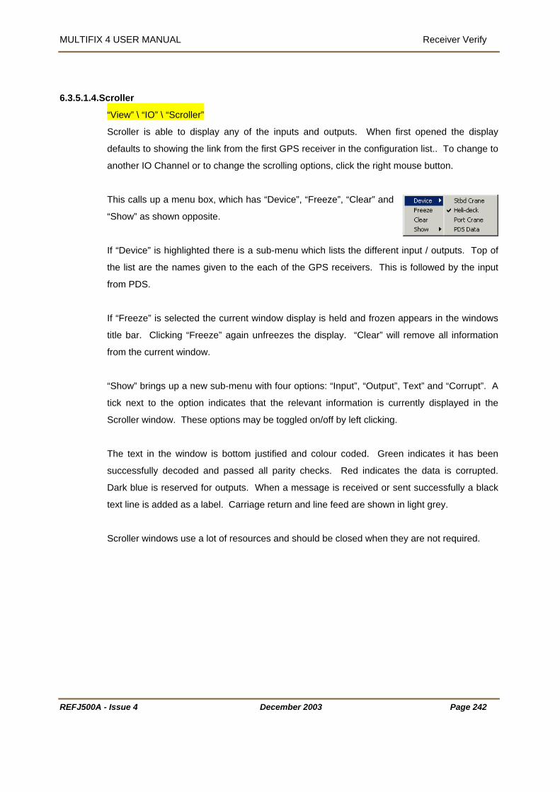
MULTIFIX 4 USER MANUAL Receiver Verify
REFJ500A - Issue 4 December 2003 Page 242
6.3.5.1.4.Scroller
“View” \ “IO” \ “Scroller”
Scroller is able to display any of the inputs and outputs. When first opened the display
defaults to showing the link from the first GPS receiver in the configuration list.. To change to
another IO Channel or to change the scrolling options, click the right mouse button.
This calls up a menu box, which has “Device”, “Freeze”, “Clear” and
“Show” as shown opposite.
If “Device” is highlighted there is a sub-menu which lists the different input / outputs. Top of
the list are the names given to the each of the GPS receivers. This is followed by the input
from PDS.
If “Freeze” is selected the current window display is held and frozen appears in the windows
title bar. Clicking “Freeze” again unfreezes the display. “Clear” will remove all information
from the current window.
“Show” brings up a new sub-menu with four options: “Input”, “Output”, Text” and “Corrupt”. A
tick next to the option indicates that the relevant information is currently displayed in the
Scroller window. These options may be toggled on/off by left clicking.
The text in the window is bottom justified and colour coded. Green indicates it has been
successfully decoded and passed all parity checks. Red indicates the data is corrupted.
Dark blue is reserved for outputs. When a message is received or sent successfully a black
text line is added as a label. Carriage return and line feed are shown in light grey.
Scroller windows use a lot of resources and should be closed when they are not required.

MULTIFIX 4 USER MANUAL Receiver Verify
REFJ500A - Issue 4 December 2003 Page 243
6.3.5.2. GPS
“View” \ “GPS”
ynch 6.3.5.2.1.S
“View” \ “GPS” \ “Synch”
The GPS Synch display can be used to check that
the time stamped data is being synchronised. The
g
he ID number for each receiver is the internal ID
number associated with the GPS receiver. If all the
data is correctly synchronised then the receiver is marked “Yes”.
The time given at the top of the table is the time for the measurement synchronisation.
6.3.5.2.2.Clock
display will flash the result every epoch confirmin
that the data is in synch.
T
“View” \ “GPS” \ “Clock”
As can be seen, GPS Time was 13 seconds ahead of UTC Time when this screen dump was
taken.
It is possible to include extra clocks in this display by right clicking in the window and selecting
“Add Local…”.
Enter a name for the clock and the time offset, in the format (hh:mm:ss), then click [OK].

MULTIFIX 4 USER MANUAL Receiver Verify
REFJ500A - Issue 4 December 2003 Page 244
These can be used to provide a local time offset from UTC for the work area.
Right clicking on the window now provides extra options to “Edit”, “Delete”, or “Hide” the
additional clock(s).
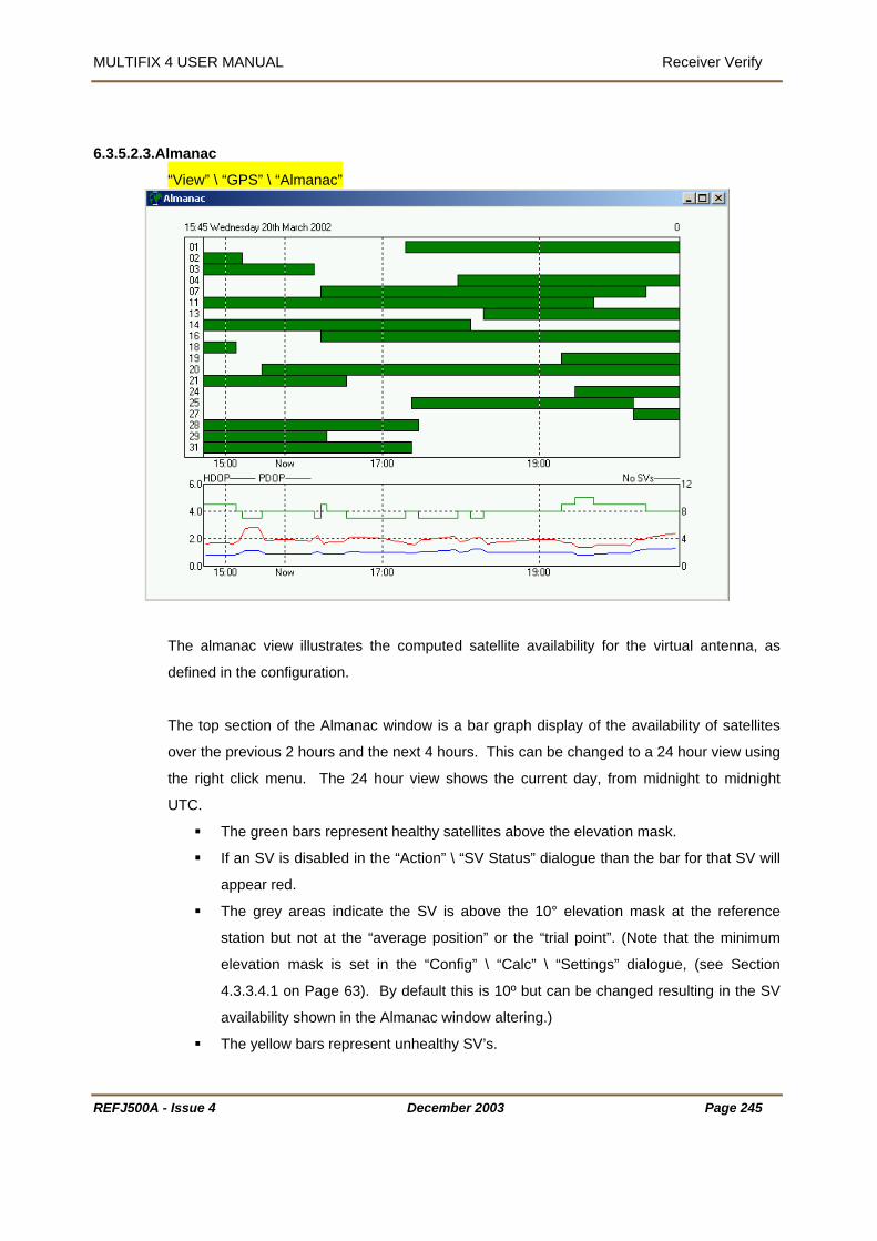
MULTIFIX 4 USER MANUAL Receiver Verify
REFJ500A - Issue 4 December 2003 Page 245
6.3.5.2.3.Almanac
“View” \ “GPS” \ “Almanac”
The almanac view illustrates the computed satellite availability for the virtual antenna, as
defined in the configuration.
The top section of the Almanac window is a bar graph display of the availability of satellites
over the previous 2 hours and the next 4 hours. This can be changed to a 24 hour view using
the right click menu. The 24 hour view shows the current day, from midnight to midnight
UTC.
The green bars represent healthy satellites above the elevation mask.
If an SV is disabled in the “Action” \ “SV Status” dialogue than the bar for that SV will
appear red.
The grey areas indicate the SV is above the 10° elevation mask at the reference
station but not at the “average position” or the “trial point”. (Note that the minimum
elevation mask is set in the “Config” \ “Calc” \ “Settings” dialogue, (see Section
4.3.3.4.1 on Page 63). By default this is 10º but can be changed resulting in the SV
availability shown in the Almanac window altering.)
The yellow bars represent unhealthy SV’s.

MULTIFIX 4 USER MANUAL Receiver Verify
REFJ500A - Issue 4 December 2003 Page 246
The lower section shows the Number of SV’s, PDOP and HDOP on a line graph over the time
period specified.
The number of satellites available for the selected position calculation is shown as a
solid green line.
The number of satellites visible at both the reference station(s) and the selected
position is a green dashed line (where applicable).
PDOP at the selected position as a red dashed line.
PDOP based on the common satellites above the masks as a red solid line
HDOP at the selected position is shown as a blue dashed line
HDOP based on the common satellites above the masks as a blue solid line
If “Network” is selected the Almanac window is based on the current “average position” or the
“trial point” and will show a green availability bar if there is at least one of the reference
stations that has a common satellite. If the bar is grey then the satellite is available at the
“Average” position or “Trial Point” position but not at any of the reference stations.
It is worth noting that MultiFix 4 uses “Elevation Delta” for rising and setting satellites.
“Elevation Delta” is a variable weighting of the satellite data in the position solution. The
minimum elevation when a satellite starts to be used and the number of degrees above the
minimum at which the satellite attains full weighting are set in the “Config” \ “Calc” \ “Settings”
dialogue referred to above.

MULTIFIX 4 USER MANUAL Receiver Verify
REFJ500A - Issue 4 December 2003 Page 247
6.3.5.2.4.Ephemeris
“View” \ “GPS” \ “Ephemeris”
The Ephemeris window shows the previous 6-hour period. The Ephemeris issue number is
placed at the time when an update was received. The issue number typically increments by 1
but that is not always the case. The majority of updates occur every 2 hours. Updates
between this period may be due to a rising SV.
A right-mouse click on the window provides the
“Copy” and “Save As…” facilities.

MULTIFIX 4 USER MANUAL Receiver Verify
REFJ500A - Issue 4
6.3.5.2.5.Constellation
“View” \ “GPS” \ Constellation
The Constellation window
shows the position of the
satellites as seen on each of
the GPS receivers.
The outer ring of each
Bullseye refers to 0° elevation, the centre is the zenith. The bottom centre of the SV numbers
text is the current position, as shown below
The satellite numbers a
Green - indicat
Yellow - indic
approaching th
Red - indicate
threshold value
Blue - means t
been acquired,
Grey - indicate
output to MultiF
When the window is r
constellation displays to
December 2003 Page 248
14
re colour coded.
es there are valid measurements available for use in the calculation.
ates there are useable measurements available, but that they are
e residual threshold and may to subject to some level of degradation.
s that measurements are available but they exceed the residual
and are therefore not used in the calculation.
hat a satellite is expected but no corrections for that satellite have yet
which may be due to the satellite being set to unhealthy.
s that a satellite is viewable from just one receiver and will not be
ix as it is not possible to check the validity of the measurements.
esized by click and dragging a corner, the program rearranges the
best fit the available area.

MULTIFIX 4 USER MANUAL Receiver Verify
REFJ500A - Issue 4 December 2003 Page 249
6.3.5.3. Status
6.3.5.3.1.Status
“View” \ “Status” \ “Rx Status”
The Status display forms the primary display for RxV. The display provides a graphical
summary of the measurement quality provided by each receiver, and the corresponding
availability of data out put.
Green indicates there are valid measurements available for use in the calculation.
Yellow indicates there are useable measurements available, but that they are
approaching the residual threshold and may to subject to some level of degradation.
Red indicates that although measurements are available they exceed the residual
threshold value and are not used in the calculation.
Blue means that a satellite is expected but no corrections for that satellite have yet
been acquired, which may be due to the satellite being set to unhealthy.
Grey Indicates that a satellite is viewable from just one receiver and will not be output
to MultiFix as it is not possible to check the validity of the measurements.

MULTIFIX 4 USER MANUAL Receiver Verify
REFJ500A - Issue 4 December 2003 Page 250
The display has a right click menu allowing the user to configure
the display. The listing of the SVs can be sorted either by PRN
number, for identification purposes, or elevation for monitoring purposes. SVs are listed by
highest elevation first.
The Show menu allows the user to add details to the display,
including the computed “Offsets” and the “Pseudoranges”
Selecting Offsets will show the offset between the transposed pseudorange and the
computed value for the virtual antenna. This is displayed in the individual colour coded status
boxes. The actual computed pseudoranges can also be displayed by selecting
“Pseudoranges”. This will display the computed pseudorange for the virtual antenna position.
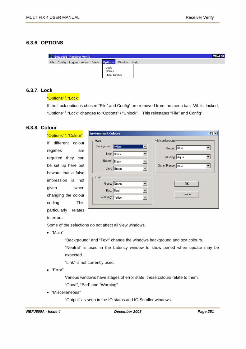
MULTIFIX 4 USER MANUAL Receiver Verify
REFJ500A - Issue 4 December 2003 Page 251
6.3.6. OPTIONS
File Config Logger Action View
Receiver Verify
LockColour
Setup001 - MultiFix3 MultiFix
Options Window Help
Hide Toolbar
6.3.7. Lock “Options” \ “Lock”
If the Lock option is chosen “File” and Config” are removed from the menu bar. Whilst locked,
“Options” \ “Lock” changes to “Options” \ “Unlock”. This reinstates “File” and Config”.
6.3.8. Colour “Options” \ “Colour”
If different colour
regimes are
required they can
be set up here but
beware that a false
impression is not
given when
changing the colour
coding. This
particularly relates
to errors.
Some of the selections do not affect all view windows.
• “Main”
“Background” and “Text” change the windows background and text colours.
“Neutral” is used in the Latency window to show period when update may be
expected.
“Link” is not currently used.
• “Error”.
Various windows have stages of error state, these colours relate to them.
“Good”, “Bad” and “Warning”.
• “Miscellaneous”
“Output” as seen in the IO status and IO Scroller windows.

MULTIFIX 4 USER MANUAL Receiver Verify
REFJ500A - Issue 4 December 2003 Page 252
“Missing” as seen in the Status and Constellation windows.
“Out of Range” as seen in the Status and Constellation windows
6.3.9. Hide Tool Bar “Options” \ “Hide Tool Bar”
This will hide the shortcut toolbar displayed at the top of the MultiFix screen.
When hidden the option will change to “show toolbar” which will return the toolbar to the
screen when selected.
6.3.10.WINDOWS
File Config Logger Action View Options
Setup001 - Receiver Verify MultiFix3
Help
TileClose All
1 IO Status2 Almanac3 Constellation4 Ephemeris
Setup001 - Receiver Verify MultiFix3
Window Help
The list will change depending on the number and types of windows that are open at any one
time.
6.3.10.1.Tile
“Window” \ “Tile”
The tile command causes the application workspace to be reduced to the display area. The
windows that are not minimised are fitted into the display area and the minimised windows
are neatly stacked along the bottom of the screen.
6.3.10.2.Close All
“Window” \ “Close All”
The close all command does just that. All the windows irrespective of their status will be
closed. As there is no confirmation required be careful not to use it in error.
6.3.10.3.The Open Windows
The “Window” drop down will also list all the windows currently open. Windows can be
overlain one on top of another and it can be difficult to locate an obscured window. Clicking
the window in the list causes the focus to shift to that window, the title bar is highlighted and it

MULTIFIX 4 USER MANUAL Receiver Verify
will appear on top of all the other windows. If there is an extended application workspace,
ow is off screen, the display area will not move to show the window but
e title bar of the window will still become highlighted.
and the selected wind
th
If there are more than 9 windows open the bottom line of the menu will be “More Windows…”
If this is selected a dialogue opens listing all windows. Highlight one of them and close the
dialogue.
REFJ500A - Issue 4 December 2003 Page 253

MULTIFIX 4 USER MANUAL Receiver Verify
REFJ500A - Issue 4 December 2003 Page 254
6.3.11.HELP
File Config Logger Action View
Dongle...PerformanceAbout...
Setup001 - Receiver Verify MultiFix3 File Options Window
Setup001 - Receiver Verify Help
6.3.11.1.Dongle
“Help” \ “Dongle…” provides the information stating
• which programs the DK2 is authorised to run
• the time limit of the dongle
• the amount of use the dongle has already had.
At all times RxV is being run, the dongle is required
in the computer’s parallel port. If it is removed the
program shuts down and an error message is
posted.
If the time limit of the dongle expires the program
shuts down and an expiry message is posted.
It is possible to revalidate the dongle by running the PROLIVE program and making a call to
the Technical Support Group. The same program plus a telephone call can also be used to
terminate a dongle so that it is no longer valid and no longer re-charged
The list in the above dialogue requires refers to certain programs in the Zero Suite. SKYNET
is a differential correction monitoring package and GENESIS is a Long Range RTK system
that uses a similar software package to MultiFix
Several other programs in the Zero suite are not listed but they also require a dongle that
must be validated for MultiFix 4. These are POSITIONVIEW, QUAL2 and LOGPUMP. Each
of these 3 programs only requires the dongle when first being run. After the initial validation,
the dongle can be removed.

MULTIFIX 4 USER MANUAL Receiver Verify
6.3.11.2.Performance
“Help” \ “Performance”
Performance window shows how the program is handling the data acquisition and
calculation process with the available resources. The window does not take into account
other programs that are running
simultaneously.
The graphs will be green below 50%,
llow between 50% and 75% and red
.
is important there is enough time for all
ions, by having fewer computations and by closing windows.
The
ye
when above 75%
It
the processes to be completed in an
orderly fashion. If there are too few resources the position solution may lag. The demand on
the processor can be reduced by accessing only the data from the RTCM reference stations
used in the computat
The performance information can also be seen in the bar at the bottom of the application
window next to the UTC Time.
6.3.11.3.About
“Help” \ “About…” provides the version number and release date
REFJ500A - Issue 4 December 2003 Page 255
MULTIFIX 4 USER MANUAL Receiver Verify
6.4. Rx
o optimise the operation of the LOG PUMP program not only must the Zero Log Files be
f LOGPUMP and RxV replay are to be found in Technical Manual
M-076, which, at time of writing, is at Issue 0.
V REPLAY When data has been logged it is possible to re-inject that same information into RxV by using
the program LOG PUMP.
LOG PUMP will read the Zero Log Files recorded by RxV and create outputs, which RxV can
accept as source data.
T
available but it is essential that the configuration and other associated files are available as
well.
Instructions on the use o
O
REFJ500A - Issue 4 December 2003 Page 256

MULTIFIX 4 USER MANUAL Soccer
7. SOCCER CTION
Soccer is a communication program that allows data on physical ports to be made available
on Internet TCP/IP sockets and vice versa. Therefore the Soccer program enables a sharing
of resources over a local network of computers using COM ports or sockets, or to one PC
running several programs concurrently. It is a means of streaming raw data to one or more
The text in this manual conforms to certain conventions
1. All command buttons are shown bold and bracketed with square brackets e.g. [OK],
hen a keyboard key is represented, it is shown bold and bracketed by greater than and
. <spacebar>.
7.1. INTRODU
users.
1
12. W
lesser than symbols e.g
13. Each dialogue has a title. When the name is in the text it is underlined e.g. Edit GPS
Receiver.
14. Direct quotations from dialogues or edit control slots are shown in normal text in
quotations, e.g. “IO Channel:”
REFJ500A - Issue 4 December 2003 Page 257
MULTIFIX 4 USER MANUAL Soccer
REFJ500A - Issue 4 December 2003 Page 258
7.2. CONFIGURATION
7.2.1. HARDWARE REQUIREMENTS
Soccer requires the following:
A PC running Windows 98, Windows NT or Windows 2000 operating system. The minimum
recommended specifications are a 350 MHz Pentium II processor with 32 MB RAM. A
graphics resolution of at least 1024 by 768 pixels is advised in order to achieve maximum
clarity of all the graphics displays. If Soccer is used in conjunction with MultiFix then please
see MultiFix Hardware Requirements for a list of minimum specifications.
For the installation of the software the PC requires a CD-ROM drive. It is possible to create
installation floppy discs from the installation menu on the CD but 8 floppies are needed.
Assuming data is not being input or output over network sockets, the PC needs a minimum of
2 COM ports. One COM port is used for two-way communications to the GPS receiver and
the second COM port for the input of RTCM corrections. As the second port is for input only it
can also be used to output position messages by using a special breakout cable.
If there is more than one RTCM delivery system, or data is to be output on several ports, then
additional COM ports will normally be required. These can be any proprietary asynchronous
serial board (or PCMCIA card). The Windows drivers for these allow the board’s (or card’s)
ports to be mapped as additional COM ports.
7.2.2. TO RUN SOCCER Soccer can be opened a variety of ways.
Use Windows Explorer to display the contents of the folder containing the Soccer program
files and double-click the “Soccer” application icon.
Select “Start” \ “Programs” \ “MultiFix 4 Vx.xx” \ “Soccer”.

MULTIFIX 4 USER MANUAL Soccer
7.3. REAL TIME OPERATION
7.3.1. FILE
7.3.1.1. New
“File” \ “New…”
o start a new Soccer configuration select this option.
e aware that starting a new configuration file will close the existing configuration and cease
al time operation if the program is already in use. Soccer will request confirmation before
losing the existing configuration file and if the configuration has not been saved the user will
t the bottom of the menu is a list of recently used configuration files. Clicking on one of
ese files opens up the chosen configuration.
7.3.1.2. Op
T
B
re
c
again be prompted.
A
th
en
“File” \ “Open…”
is facility to
elect it.
at are not compatible with the version of Soccer that
ntly being run. However if the configuration file version is the same they can be used
ven though created by a different program version.
g the
REFJ500A - Issue 4 December 2003 Page 259
When initially opened the program
does not know which configuration file
to use. If a previously prepared
configuration exists use th
s
The configuration files contain the
program name and version identifiers
in a file header. They also include a configuration file version number. The program will not
allow configuration files to be opened th
is curre
e
File open can also be accomplished usin button.

MULTIFIX 4 USER MANUAL Soccer
7.3.1.3. Save
“File” \ “Save”
atically saved when changes are made. This facility is
erefore used to update the configuration file with the current settings. If the set-up is being
not have an identity, the use of
n the Save As dialogue where a file name must be entered. Once a
onfiguration file has been named, the use of “File” \ “Save” performs a save without calling
he name of the current configuration file appears in the application workspace title bar. If
ve not been saved, that file name has an “*”
moved. File saving can also be
The configuration file is not autom
th
undertaken for the first time and the configuration file does
“File” \ “Save” will ope
c
up the Save As dialogue.
T
configuration changes are made that ha
appended to it. After using File \Save the “*” is re
accomplished using the button.
ve As 7.3.1.4. Sa
“File” \ “Save As…”
If the latest configuration is to be saved without overwriting the current configuration file use
eate a new file leaving the previous
he current configuration file.
he Save As dialogue requires the operator to enter a name for the new configuration file. If
an existing file name is entered the program will overwrite that file.
7.3.1.5. Exit
the “File” \ ”Save As…” option. This gives the option to cr
file intact. The program immediately uses the new file as t
T
“File” \ “Exit”
This exit route is immediate if no configuration file is loaded.
Confirmation is required if a configuration file is in use. The user will be prompted to save the
configuration if they have not already done so.
If the program is exited using the button when the current configuration has not been
saved, a dialogue is presented asking whether to save the configuration prior to exit or
whether to cancel the exit. If there have been no configuration changes then the program will
terminate immediately.
REFJ500A - Issue 4 December 2003 Page 260

MULTIFIX 4 USER MANUAL Soccer
7.3.2. CONFIG
7.3.2.1. IO
“Config” \ “IO”
7.3.2.1.1.Comm
“Config” \ “IO” \ “Comm…”
E
REFJ500A - Issue 4 December 2003 Page 261
arlier it was explained that the “Programs” / “MultiFix 4 Vx.xx” / “IO Config” applet needed to
s available (see section 3.4 on
dialogue box that is presented when
onfig” \ “IO” \ “Comm…” is selected.
pens another dialogue box for
lick the [Enable] button to activate the port
be run after installation to define what ports the computer ha
page 13). The parameters selected there determine the
“C
Highlight one of the ports to be used and click [Edit]. This o
setting the port parameter settings.
C
and set the Baud Rate, Data Bits, Parity and
Stop Bits.

MULTIFIX 4 USER MANUAL Soccer
REFJ500A - Issue 4 December 2003 Page 262
7.3.2.1.2.Sockets
“Config” \ “IO” \ “Socket…”
To be able to distribute and receive data over a network via sockets assumes each computer
has Transmission Control Protocol / Internet Protocol (TCP/IP) installed. Sockets have the
advantage over COM ports in that two or more programs can access the same data.
Sockets can transfer data between programs running on different computers or between two
or more programs running on the same computer. (If a standalone (non-networked) computer
running Windows NT is used and the data is to be shared between multiple programs running
on that PC then the MS Loopback Adapter network adapter must be installed).
The TCP/IP protocol is a family of protocols that allow Internet data communication. Included
in that family are two transport layer protocols, the Transport Control Protocol (TCP) and the
User Datagram Protocol (UDP). Soccer supports both these transport protocols from Version
1.25 onwards.
• The Transport Control Protocol establishes sessions between a Server and however
many Clients that are accessing that Server. There is continual presence checking and
acknowledging between each Server/Client pairs with messages always received in the
order they were issued. A Server does not have control of the number of Clients that
access the socket on which data is being presented. (It is often perceived that the Server
provides data and the Client receives data, but once the connection is established the link
is two-way).
• The User Datagram Protocol does not have the end-to-end checking overhead of the
TCP. Instead packets of data are simply issued to the Internet in either broadcast mode,
where any networked computer on the LAN can receive them, or in addressed mode
where the data packets have headers specifying the addressees for whom the packets
are intended. There is no guarantee with this protocol that the messages will arrive in the
order they were issued. When setting up “Ribbons” to output datagrams a time interval
can be specified to prevent data becoming corrupted, see section on “Ribbons” 7.3.2.2.
Broadcast datagrams cannot pass routers linking Local Area Networks (LAN) unless
specifically configured.
For most situations where Local Area Networks are involved Server / Client TCP sockets are
the best choice Internet transport protocols.

MULTIFIX 4 USER MANUAL Soccer
7.3.2.1.2.1.The Soccer Computer as a TCP Client
th a Server, the operator must know the IP address (or the
etwork identification name - see below) of the Server computer and the port number the
First, in the “PC Names” table click
efining the server PC.
If the numerical IP address is known,
[Resolve>>]. Click [OK].
’s network identification name is, and if all
computers involved are aware of local naming services (WINS / DNS), then type in the
computer’s name in the “Address:” slot and click [Resolve>>]. Once the computer is found,
its IP address will appear as shown. If required, use [>>Literal] to transfer the name and
ddress to their named slots. Click
K].
normal in a network for computers
dress has changed, it will not be able to re-locate it. If the Client PC has the name
For a Client to make contact wi
n
Server is outputting the required data.
[New].
There are two possible ways of
d
enter a PC name in “Name:” and the IP
address in “Address:” and click
If the IP address is not known but the computer
a
[O
It is
to be allocated new IP addresses
when the PC is restarted. If the Client PC has a numerical entry for the address and the
Server’s ad
REFJ500A - Issue 4 December 2003 Page 263

MULTIFIX 4 USER MANUAL Soccer
of the Server PC in the address slot, it will automatically search to re-locate the Server PC by
name. Assuming it is found, the Client PC will obtain the Server PC’s current address.
the “Sockets” table click [New].
ck the “Client” radio button and select the ”PC
Name:” of the server.
he Server PC is
default name if required.
7.3.2.1.2.2.The Soccer Computer as a TCP Server
no
he Soccer computer to the PC table; the
rogram already knows the computer’s IP address. This
” \
a
e data will be
In
Now che
Enter the number of the port on which t
presenting the data. Change the socket’s
If the Soccer computer is to be a server then there is
need to add t
p
can be seen in the window called up by “View
“Sockets”, see 7.3.5.2 on page 273.
In the “Sockets” table click [New]. Give the socket
name and enter the Port number that th
output on. Click [OK] to exit.
REFJ500A - Issue 4 December 2003 Page 264
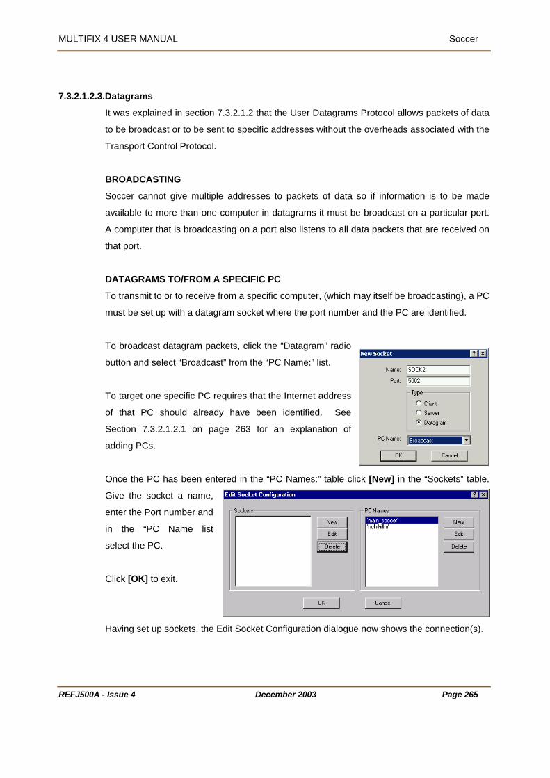
MULTIFIX 4 USER MANUAL Soccer
7.3.2.1.2.3
.1.2 that the User Datagrams Protocol allows packets of data
be broadcast or to be sent to specific addresses without the overheads associated with the
occer cannot give multiple addresses to packets of data so if information is to be made
utton and select “Broadcast” from the “PC Name:” list.
of that PC should already have been identified. See
Section 7.3.2.1.2.1 on page 263 for an explanation of
adding PCs.
Once the PC has been entered in the “PC Names:” table click [New] in the “Sockets” table.
Give the socket a name,
enter the Port number and
in the “PC Name list
select the PC.
Click [OK] to exit.
Having set up sockets, the Edit Socket Configuration dialogue now shows the connection(s).
.Datagrams
It was explained in section 7.3.2
to
Transport Control Protocol.
BROADCASTING
S
available to more than one computer in datagrams it must be broadcast on a particular port.
A computer that is broadcasting on a port also listens to all data packets that are received on
that port.
DATAGRAMS TO/FROM A SPECIFIC PC
To transmit to or to receive from a specific computer, (which may itself be broadcasting), a PC
must be set up with a datagram socket where the port number and the PC are identified.
To broadcast datagram packets, click the “Datagram” radio
b
To target one specific PC requires that the Internet address
REFJ500A - Issue 4 December 2003 Page 265

MULTIFIX 4 USER MANUAL Soccer
7.3.2.2. Ribbon
“Config” \ “Ribbon”
7.3.2.2.1.New
“Config” \ “Ribbon” \ “New…”
ort.
“Config” \ “Ribbon” \ “New…” and the New
Ribbon window (shown right) will appear. Give the
the relevant Input and
If using TCP
l” to be set to prevent the data becoming
This interval refers to the time Soccer waits after receiving incoming packets of
he program on the relevant port or socket.
7.3.2.3. Test
In order to output any data from Soccer it is necessary to define a pathway between the
incoming and outgoing data within the program. Data can be output either on a socket port or
an available COM p
Select
ribbon a name and then select
Output location.
The “Mode” section should only be used when
outputting data using datagrams.
sockets then the default selection “Immediate” should be used. As datagrams are random
packets of data Soccer allows for an “Interva
corrupted.
data before re-sending the data out as datagrams. This helps prevent incoming data packets
being randomly split before they are re-sent. It is recommended that the default value 0.01
should be used but this can be increased if corrupted data is seen.
To apply this ribbon click [OK]. From the “View” menu select “IO Status”. The Output
column should show data being output from t
logger
“Config” \ “Text Logger”
REFJ500A - Issue 4 December 2003 Page 266

MULTIFIX 4 USER MANUAL Soccer
REFJ500A - Issue 4 December 2003 Page 267
7.3.2.3.1.New
“Config” \ “Text Logger” \ “New”
Data can be logged as a text file. Any number of Text loggers can be set up to log to separate
files.
Select “New..” to define the file name and locations
of the log file to be created.
You will also need to define the IO channel you wish
to log.
Soccer can distinguish between data coming into and
going out of an IO port. The user can select to log
with incoming, outgoing or both sets of data.
7.3.3. LOGGER
The Logger menu items will change depending on the current state of logging. If no logging is
occurring it will display “Edit” and “Start”.
If logging has been started it will display “Pause” and “Stop”.
If logging is paused it will display “Resume” and “Stop”.
Using this menu Zero files are logged. These files can be read by LOGPUMP (See Section
8)
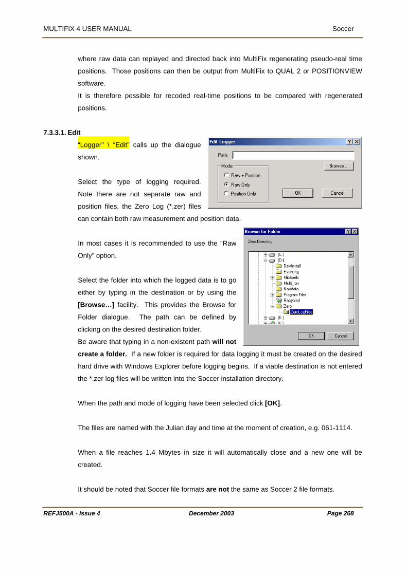
MULTIFIX 4 USER MANUAL Soccer
where raw data can replayed and directed back into MultiFix regenerating pseudo-real time
s. Those positions can then be output from MultiFix to QUAL 2 or POSITIONVIEW
It is therefore possible for recoded real-time positions to be compared with regenerated
positions.
7.3.3.1. Edit
position
software.
“Logger” \ “Edit” calls up the dialogue
shown.
Select the type of logging required.
Note there are not separate raw and
osition files, the Zero Log (*.zer) files
can contain both raw measurement and position data.
In most cases it is recommended to use the “Raw
Only” option.
Select the folder into which the logged data is to go
either by typing in the destination or by using the
[Browse…] facility. This provides the Browse for
older dialogue. The path can be defined by
clicking on the desired destination folder.
Be aware that typing in a non-existent path will not
create a folder. If a new folder is required for data logging it must be created on the desired
hard drive with Windows Explorer before logging begins. If a viable destination is not entered
the *.zer log files will be written into the Soccer installation directory.
When the path and mode of logging have been selected click [OK].
The files are named with the Julian day and time at the moment of creation, e.g. 061-1114.
When a file reaches 1.4 Mbytes in size it will automatically close and a new one will be
created.
It should be noted that Soccer file formats are not the same as Soccer 2 file formats.
p
F
REFJ500A - Issue 4 December 2003 Page 268

MULTIFIX 4 USER MANUAL Soccer
7.3.3.2. Starting, Stopping and Pausing
“Logger” \ “Start” is a command.
The same is accomplished using the toolbar button.
This will start the logging process. When data is being logged the menu options and toolbar
buttons will change to “Pause” and “Stop”.
“Pause” will arrest the logging process until “Resume” or “Stop” are selected.
will restart logging into the existing file.
When logging is started a Logging Schedule file is created in the same folder as the Soccer
UMP can be set up correctly for the output of
ion number, reference station and calculation
so if logging is stopped and then re-started the
existing file is overwritten. This means that if configuration changes have been made
between one log session and subsequent log sessions the Logging Schedule file will only be
relevant for the last session. Therefore, if changes are to be made after logging is stopped
use Explorer to make a copy of the Schedule file and keep a note of the *.zer log files to
which it relates. Do not make configuration changes while logging is on going.
When being archived or when being forwarded for replay analysis, the configuration files
be kept with the log files.
“Resume” uses the same button as Start and
“Stop” will close the current log file.
application. This file is needed so that LOGP
data. The schedule contains the Soccer vers
status information. There is only one file
(including the schedule file) should
REFJ500A - Issue 4 December 2003 Page 269
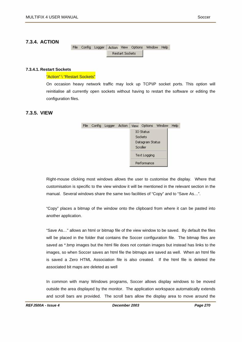
MULTIFIX 4 USER MANUAL Soccer
7.3.4. ACTION
start Sockets 7.3.4.1. Re
“Action” \ “Restart Sockets”
reinitialise all currently open sockets without having to restart the software or editing the
onfiguration files.
7.3.5. VIEW
On occasion heavy network traffic may lock up TCP\IP socket ports. This option will
c
Right-mouse clicking most windows allows the user to customise the display. Where that
the
configuration file. The bitmap files are
saved as *.bmp images but the html file does not contain images but instead has links to the
images, so when Soccer saves an html file the bitmaps are saved as well. When an html file
is saved a Zero HTML Association file is also created. If the html file is deleted the
associated bit maps are deleted as well
In common with many Windows programs, Soccer allows display windows to be moved
outside the area displayed by the monitor. The application workspace automatically extends
and scroll bars are provided. The scroll bars allow the display area to move around the
customisation is specific to the view window it will be mentioned in the relevant section in
manual. Several windows share the same two facilities of “Copy” and to “Save As…”.
“Copy” places a bitmap of the window onto the clipboard from where it can be pasted into
another application.
“Save As…” allows an html or bitmap file of the view window to be saved. By default the files
will be placed in the folder that contains the Soccer
REFJ500A - Issue 4 December 2003 Page 270

MULTIFIX 4 USER MANUAL Soccer
extended application workspace. There is no limit on the number of windows of any type that
can be open in the application workspace. Multiple copies of the same window type can be
open. Indeed it will be seen that once a window is open some types of window allow further
selection of the data that is to appear in them.
Display Area
Extended Application Workspace Horizontal Scroll Bar Vertical Scroll Bar
Setup001 - MultiFix 3
File Config Logging Action View Options Tools Window Help
Multi Fix 3
Loading 12% Response 5% 1:03:25 pm UTC
Display Area
Extended Application Workspace Horizontal Scroll Bar Vertical Scroll Bar
Setup001 - Soccer
File Config Logger Action View Options Window HelpFix 3 Fix 3
Loading 12% Response 5% 1:03:25 pm UTC
Figure 15 Windows Extending Beyond the Application Workspace
Most windows can be resized by clicking and dragging the corners or sides. Some windows
that contain text will wrap the text message into the available space. Other windows
containing text will simply be cropped as the window size reduces. Windows containing
graphical information will resize down to a minimum and will then either crop the information
or will introduce scroll bars.
REFJ500A - Issue 4 December 2003 Page 271
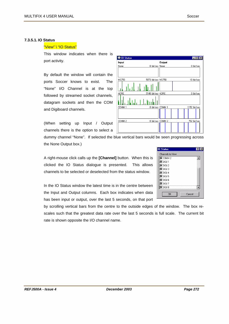
MULTIFIX 4 USER MANUAL Soccer
REFJ500A - Issue 4 December 2003 Page 272
7.3.5.1. IO Status
“View” \ “IO Status”
This window indicates when there is
port activity.
By default the window will contain the
ports Soccer knows to exist. The
“None” I/O Channel is at the top
followed by streamed socket channels,
datagram sockets and then the COM
and Digiboard channels.
(When setting up Input / Output
channels there is the option to select a
dummy channel “None”. If selected the blue vertical bars would be seen progressing across
the None Output box.)
A right-mouse click calls up the [Channel] button. When this is
clicked the IO Status dialogue is presented. This allows
channels to be selected or deselected from the status window.
In the IO Status window the latest time is in the centre between
the Input and Output columns. Each box indicates when data
has been input or output, over the last 5 seconds, on that port
by scrolling vertical bars from the centre to the outside edges of the window. The box re-
scales such that the greatest data rate over the last 5 seconds is full scale. The current bit
rate is shown opposite the I/O channel name.
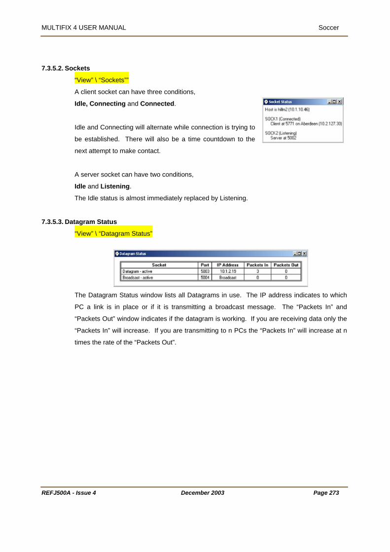
MULTIFIX 4 USER MANUAL Soccer
7.3.5.2. Sockets
“View” \ “Sockets””
t can have three conditions,
ected.
Idle and C
be establ time countdown to the
next attempt to make contact.
A server socket can have two conditions,
Idle and Listening.
7.3.5.3. Datagram Status
A client socke
Idle, Connecting and Conn
onnecting will alternate while connection is trying to
ished. There will also be a
The Idle status is almost immediately replaced by Listening.
“View” \ “Datagram Status”
The Datagram Status window lists all Datagrams in use. The IP address indicates to which
ink is in place or if it is transmitting a broadcast message. The “Packets In” and
“Packets Out” window indicates if the datagram is working. If you are receiving data only the
PC a l
“Packets In” will increase. If you are transmitting to n PCs the “Packets In” will increase at n
times the rate of the “Packets Out”.
REFJ500A - Issue 4 December 2003 Page 273

MULTIFIX 4 USER MANUAL Soccer MULTIFIX 4 USER MANUAL Soccer
REFJ500A - Issue 4 December 2003 Page 274
7.3.5.4. Scroller
“View” \ “Scroller”
Scroller is able to display any data that is input or output in Soccer. When first opened the
display defaults to showing the link to/from the GPS receiver. To change to another IO
Channel or to change the scrolling options, click the right mouse button.
This calls up a menu box, which has “Device”, “Freeze”, “Clear” and “Show” as shown below.
If “Device” is highlighted there is a sub-menu which lists the
different input / outputs. Top of the list is the name given to
the GPS receiver. This is followed by the RTCM source(s)
and then by the output(s).
If “Freeze” is selected the current window display is held and frozen appears in the windows
title bar. Clicking “Freeze” again unfreezes the display. “Clear” will remove all information
from the current window.
“Show” brings up a new sub-menu with four options: “Input”,
“Output”, Text” and “Corrupt”. A tick next to the option indicates
that the relevant information is currently displayed in the Scroller
window. These options may be toggled on or off by left clicking.
The text in the window is bottom justified and colour coded. Green indicates it has been
successfully decoded and passed all parity checks, red indicates the data is corrupted and
dark blue is reserved for the outputs, see 7.3.5.4.2.
REFJ500A - Issue 4 December 2003 Page 274

MULTIFIX 4 USER MANUAL Soccer
REFJ500A - Issue 4 December 2003 Page 275
7.3.5.4.1.RTCM Input
7.3.5.4.2.Output Strings
7.3.5.5. Text Logging
“View” \ “Text Logging”
Text Logging is not currently functional.

MULTIFIX 4 USER MANUAL Soccer
REFJ500A - Issue 4 December 2003 Page 276
7.3.6. OPTIONS
7.3.6.1. Lock
“Options” \ “Lock”
If the Lock option is chosen “File” and Config” are removed from the menu bar. Whilst locked,
“Options” \ “Lock” changes to “Options” \ “Unlock”. This reinstates “File” and Config” if
selected.
7.3.6.2. Colour
“Options” \ “Colour”
If different colour schemes are
required they can be set up here.
Ensure that a false impression is
not given when changing the
colour coding, in particular
relating to errors.
Some of the selections do not
affect all view windows.
• “Main”
“Background” and “Text” change the windows background and text colours.
“Neutral” is used in the Latency window to show period when update may be
expected.
“Link” is not currently used.
• “Error”.
Various windows have stages of error state, these colours relate to them.
“Good”, “Bad” and “Warning”.
• “Miscellaneous”
“Output” as seen in the IO status and IO Scroller windows.
“Missing” as seen in the Latency and Constellation windows.

MULTIFIX 4 USER MANUAL Soccer
“Out of Range” as seen in the Latency and Constellation windows when a satellite is
below the mask.
7.3.6.3. Hide Tool Bar
“Options” \ “Hide Tool Bar”
This will hide the shortcut toolbar displayed at the top of the MultiFix screen.
When hidden the option will change to “show toolbar” which will return the toolbar to
the screen when selected.
7.3.7. WINDOWS
The list will change depending on the number and types of windows that are open at any one
time.
7.3.7.1. Tile
“Window” \ “Tile”
The tile command causes the application workspace to be reduced to the display area. The
windows that are not minimised are fitted into the display area and the minimised windows
are neatly stacked along the bottom of the screen.
7.3.7.2. Close All
“Window” \ “Close All”
The close all command closes all windows irrespective of their status. As there is no
confirmation required be careful not to use it in error.
7.3.7.3. The Open Windows
The “Window” drop down will also list all the windows currently open. Windows can be
overlain one on top of another and it can be difficult to locate an obscured window. Clicking
the window in the list causes the focus to shift to that window, the title bar is highlighted and it
REFJ500A - Issue 4 December 2003 Page 277

MULTIFIX 4 USER MANUAL Soccer
will appear on top of all the other windows. If there is an extended application workspace,
and the selected window is off screen, the display area will not move to show the window but
the title bar of the window will still become highlighted.
If there are more than 9 windows open the bottom line of the menu will be “More indows…”
If this is selected a dialogue opens listing all windows. Highlight one of them and close the
dialogue.
W
REFJ500A - Issue 4 December 2003 Page 278

MULTIFIX 4 USER MANUAL Soccer
REFJ500A - Issue 4 December 2003 Page 279
7.3.8. HELP
7.3.8.1. Dongle
“Help” \ “Dongle…”
Provides the information stating:
• Which programs the DK2 is authorised to run
• The time limit of the dongle
• The amount of use the dongle has already had.
At all times Soccer is being run the dongle is
required in the computer’s parallel port. If it is
removed the program shuts down and an error
message is posted.
If the time limit of the dongle expires the program
shuts down and an expiry message is posted.
It is possible to revalidate the dongle by running the PROLIVE program and making a call to
the Technical Support Group. The same program plus a telephone call can also be used to
terminate a dongle so that it is no longer valid and no longer re-charged.
The list in the above dialogue requires refers to certain programs in the Zero Suite. SKYNET
is a differential correction monitoring package, GENESIS is a Long Range RTK system that
uses a similar software package to MultiFix, and RXV is a program called RECEIVER
VERIFY which is described in Section 6.
Several other programs in the Zero suite are not listed which also require a dongle validated
for Soccer. These are POSITIONVIEW, QUAL2 and LOGPUMP. Each of these 3 programs
only requires the dongle when first being run. After that the dongle can be removed.
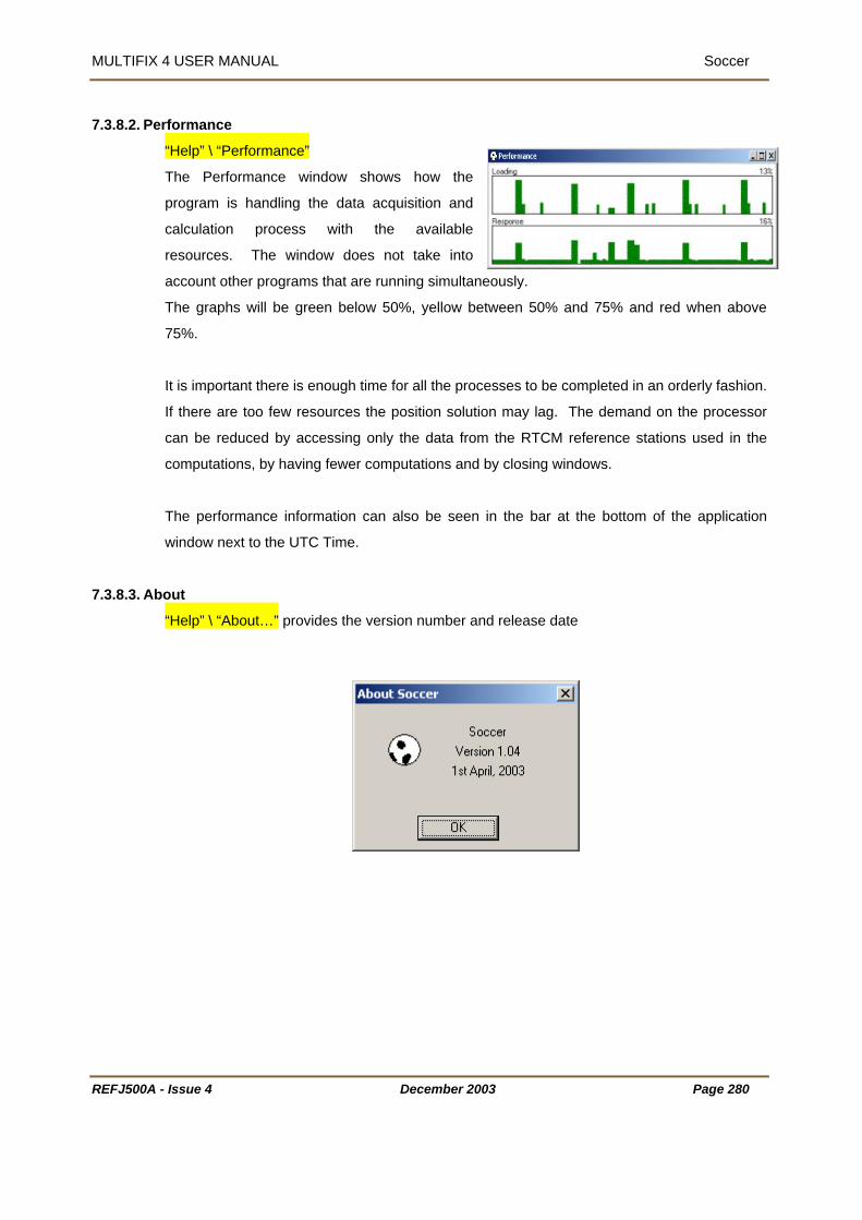
MULTIFIX 4 USER MANUAL Soccer
REFJ500A - Issue 4 December 2003 Page 280
7.3.8.2. Performance
“Help” \ “Performance”
The Performance window shows how the
program is handling the data acquisition and
calculation process with the available
resources. The window does not take into
account other programs that are running simultaneously.
The graphs will be green below 50%, yellow between 50% and 75% and red when above
75%.
It is important there is enough time for all the processes to be completed in an orderly fashion.
If there are too few resources the position solution may lag. The demand on the processor
can be reduced by accessing only the data from the RTCM reference stations used in the
computations, by having fewer computations and by closing windows.
The performance information can also be seen in the bar at the bottom of the application
window next to the UTC Time.
7.3.8.3. About
“Help” \ “About…” provides the version number and release date

MULTIFIX 4 USER MANUAL Soccer
7.4. SOCCER AND MULTIFIX 4
MultiFix takes in data from a GPS receiver and from a RTCM data link in order to compute a
position.
Using MultiFix on its own it is not possible to make the GPS or RTCM data available to ot r
programs. If another MultiFix user requires raw data it is necessary to set up an entirely new
hardware configuration for that program. Simply put, the raw data being input into the
program cannot be ‘shared’ which this may present problems with regard to available
resources.
Figure 16 Outputs Available from Soccer
To overcome the problem of sharing data the Soccer application can be used to receive the
GPS pseudo-ranges and RTCM corrections. Pathways (ribbons) are then established within
the Soccer program to enable any of this data to be made available to multiple users on a
local network via socket connections.
The diagram shown overleaf shows only one copy of Soccer running on each computer, but
he
PC 1
MultiFix 4GPS
RTCOthe
PositionString
there can be several Soccer applications running on the same PC.
REFJ500A - Issue 4 December 2003 Page 281

MULTIFIX 4 USER MANUAL Soccer
Figure 17
” \ “MultiFix 4 Vx.xx” \ “Soccer”.
configure the COM ports. Click on “Config” \ “IO” \ “Comm…” select the
ay within the program. It
hould be remembered that any data could be output
ither on a socket or an available COM port.
Outputs Available from Soccer Configuration
Connect up the hardware as per the instructions outlined in section 0. Then run up the
Soccer program by clicking “Start” \ “Programs
It is first necessary to
desired COM ports, click [Enable] then set the correct Baud Rates and Parity. This
procedure is also described in section 4.3.3.1.1 on page 53. From the “View” menu select “IO
Status”. The Input column should show data being input into the program on the relevant
COM ports.
In order to output the raw data from Soccer, it is
necessary to define a pathw
s
e
GPS RTCM Other
PositionString
PC 2
MultiFix 4
PC
MultiFix 4
PC n
PositionString
1
Soccer MultiFix 4 PositionString
REFJ500A - Issue 4 December 2003 Page 282

MULTIFIX 4 USER MANUAL Soccer
ew Ribbon window will appear. Give it a name
nd then select the relevant Input and Output location. To apply this ribbon click [OK]. From
port)
The configuration of sockets within Soccer is described in
It should be noted that the name and IP address of the host
computer is always displayed in the Socket Status window. This
can be accessed by clicking “View” \ “Sockets”.
Select “Config” \ “Ribbon” \ “New…” and the N
a
the “View” menu select “IO Status”. The Output column should show data being output from
the program on the relevant port or socket.
“Config” \ “IO” \ “Sockets…” defines the socket (which may also be regarded as a virtual
that the data will be output on.
Section 7.3.2.1.2 on page 262.
REFJ500A - Issue 4 December 2003 Page 283

MULTIFIX 4 USER MANUAL Log Pump
REFJ500A - Issue 4 December 2003 Page 284
8. LOG PUMP 8.1. INTRODUCTION
Log Pump and MultiFix 4 are two of the applications in the Zero Suite of applications. MultiFix
4 is able to form differential Iono-free solutions of position given data from a GPS receiver and
Type 1, 2, 3 and 15 or 55 RTCM Type messages. It also has the ability to record data from
its GPS receiver and any RTCM sources to which it is interfaced and to log the position
solutions. Log Pump can read and output the recorded data and pass it back into MultiFix 4
where re-computations can be performed in pseudo-real time. Log Pump also has the facility
to output the logged positions to Qual 2, where they can be statistically analysed.
This section covers the configuration and operation of the Lop Pump application and specific
points of note for the configuration of the MultiFix 4 application. For complete advice on the
set up and operation of the MultiFix 4 program see Section 4.
In common with other Zero programs
• There is no limit on the number of RTCM correction systems.
• There is no limit on the number of RTCM differential reference stations.
• There is no limit on the number of outputs
• There is no limit on the number of view windows
• Many view windows can be customised
The text in this manual conforms to certain conventions.
All dialogue command buttons are shown bold and square bracketed, e.g. [OK].
When a keyboard key is represented, it is shown bold and bracketed by greater than
and lesser than symbols e.g. <spacebar>.
Direct quotations from dialogues or edit control slots are shown in normal text in
quotations, e.g. “IO Channel:”
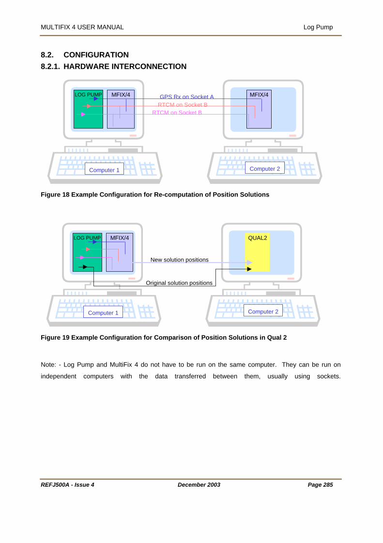
MULTIFIX 4 USER MANUAL Log Pump
8.2. CONFIGURATION WARE INTERCONNECTION
F
F
N
in
8.2.1. HARD
R
igure 18
LOG PUMP MFIX/4 MFIX/4GPS Rx on Socket ARTCM on Socket B
Computer 1
Example Configuration for Re-computation of Position Solutions
Computer 2
RTCM on Socket B
igure 19 of Position Solutions in Qual 2
ote: - Log Pump and MultiFix 4 do not have to be run on the same computer. They can be run on
dependent computers with the data transferred between them, usually using sockets.
LOG PUMP MFIX/4 QUAL2
Example Configuration for Comparison
Computer 1 Computer 2
New solution positions
Original solution positions
EFJ500A - Issue 4 December 2003 Page 285

MULTIFIX 4 USER MANUAL Log Pump
WARE REQUIREMENT ires the following:
PC has network capabilities so sockets can be used for outputting
ata.
on floppy discs from the installation menu on the CD but 8 floppies are needed.
Assuming data is not being input or output over network sockets, the PC needs a minimum of
COM port is used for two-way communications to the GPS receiver and
tem, or data is to be output on several ports, then
on workspace when a configuration file is
8.2.2. HARDLog Pump requ
A PC running Windows 98, Windows 2000 or Windows NT.
The PC will preferably be a PII or faster. A graphics resolution of at least 1024 by 768 pixels
is recommended in order to achieve maximum clarity of all the graphics displays. A faster
machine with more memory may be required if MultiFix 4 is to be used, See Section 4.2.3. It
is recommended that the
d
For the installation of the software the PC requires a CD-ROM drive. It is possible to create
installati
2 COM ports. One
the second COM port for the input of RTCM corrections. As the second port is for input only it
can also be used to output position messages by using a special breakout cable.
If there is more than one RTCM delivery sys
additional COM ports will normally be required. These can be any proprietary asynchronous
serial board (or PCMCIA card). The Windows drivers for these allow the board’s (or card’s)
ports to be mapped as additional COM ports.
8.2.3. LOG PUMP FILES Log Pump has its own configuration and persistence files that are normally stored in the folder
into which the application was installed. The persistence file contains the number, type,
position and contents of windows in the applicati
saved. It is also written when the program is exited.
Log Pump reads the *.zer files written by MultiFix 4. Zero log files are named using the Julian
day and time when opened.
REFJ500A - Issue 4 December 2003 Page 286

MULTIFIX 4 USER MANUAL Log Pump
8.3. REAL TIME OPERATION og Pump can be opened a variety of ways.
se Windows Explorer to display the contents of the folder containing the Log Pump program
les and then double-clicking the “Log Pump” application icon.
rag the “Log Pump” application icon from the Windows Explorer window onto the desktop to
create a shortcut. Thereafter double-click the shortcut.
Use “Start” \ “Programs” \ “Zero” and click “Log Pump”.
L
U
fi
D
Setup001- Zero Log Pump
REFJ500A
New Open…SaveSave A s…
Exit
File Config Items Playback Action View Options Window Help
Setup001- Zero Log Pump
IOFilesReplay Time
Comm
File Config Items Playback Action View Options W
Socket
indow Help
Setup001- Zero Log Pum p
<nam e>
F ile Config Item s P layback Action V iew O ptions W indow Help
G PS RxRTCMCom pressPositionIO
New
1 <nam e> EditDelete
New
EditDelete
New
1 <nam e> EditDelete
New
1 <nam e> EditDelete
New
1 <nam e> EditDelete
1
Setup001- Zero Log Pump
Play FastForwardPauseStop
File Config Items Playback Action View Options Window Help
Setup001- Zero Log Pump
Restart Sockets
File Config Items Playback Action View Options Window Help
- Issue 4 December 2003 Page 287

MULTIFIX 4 USER MANUAL Log Pump
REFJ500A
Figure 20
Setup001- Zero Log Pump
IOFiles PositionEphemeris
StatusSocketDatagram
Setup001- Zero Log Pump File Config Items Playback Action View Options Window Help
Scroller
LockColour
File Config Items Playback Action View Options Window Help
Hide Toolbar
Setup001- Zero Log Pump
TileClose All
1 Files 2 Position Out - Position
3 IO Status
File Config Items Playback Action View Options Window Help
Setup001- Zero Log Pump
-
L
Issue 4 December 2003 Page 288
og Pump Menu Layout
DongleAbout
File Config Items Playback Action View Options Window Help
Performance

MULTIFIX 4 USER MANUAL Log Pump
8.3.1. FIL
8.3.1.1. Ne
E
New Open…SaveSave A s…
Exit
Setup001- Zero Log Pump File Config Items Playback Action View Options Window Help
w
“File” \ “New…”
ect this option.
Be aware that starting a new configuration will close the existing configuration and the
recently used configuration files. Clicking on one
chosen configuration.
8.3.1.2. Open
To start a new Log Pump configuration sel
program will cease outputting data.
At the bottom of the “File” menu is a list of
of these files opens up the
“File” \ “Open…”
When opened the program does not know which configuration file to open. Assuming a
previously prepared configuration exists, use this facility to select it.
The configuration files have program
REFJ500A - Issue 4 December 2003 Page 289
name and version identifiers in a file
ile open can also be accomplished using
header. They also have a configuration
file version number. The program will
not allow configuration files to be
opened that are not compatible with the
version of Log Pump that is currently
being run. However if the configuration file version is the same they can be used even though
created by a different program version.
F the button.
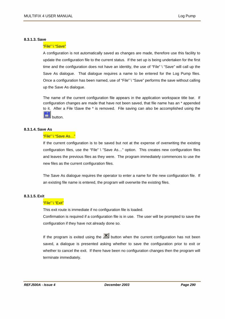
MULTIFIX 4 USER MANUAL Log Pump
8.3.1.3. Sa ve
“File” \ “Save”
A configuration is not automatically saved as changes are made, therefore use this facility to
pdate the configuration file to the current status. If the set up is being undertaken for the first
n identity, the use of “File” \ “Save” will call up the
e entered for the Log Pump files.
” performs the save without calling
appears in the application workspace title bar. If een saved, that file name has an * appended
it. After a File \Save the * is removed. File saving can also be accomplished using the
u
time and the configuration does not have a
Save As dialogue. That dialogue requires a name to b
Once a configuration has been named, use of “File” \ “Save
up the Save As dialogue. The name of the current configuration file configuration changes are made that have not bto
button.
ve As 8.3.1.4. Sa
“File” \ “Save As…”
configuration is to be saved but not at the expense of overwriting the existing
configuration files, use the “File” \ ”Save As…” option. This creates new configuration files
and leaves the previous files as they were. The program immediately commences to use the
new files as the current configuration files.
ue requires the operator to enter a name for the new configuration file. If
8.3.1.5. Ex
If the current
The Save As dialog
an existing file name is entered, the program will overwrite the existing files.
it
“File” \ “Exit”
his exit route is immediate if no configuration file is loaded.
Confirmation is required if a configuration file is in use. The user will be prompted to save the
configuration if they have not already done so.
If the program is exited using the
T
button when the current configuration has not been
saved, a dialogue is presented asking whether to save the configuration prior to exit or
whether to cancel the exit. If there have been no configuration changes then the program will
terminate immediately.
REFJ500A - Issue 4 December 2003 Page 290
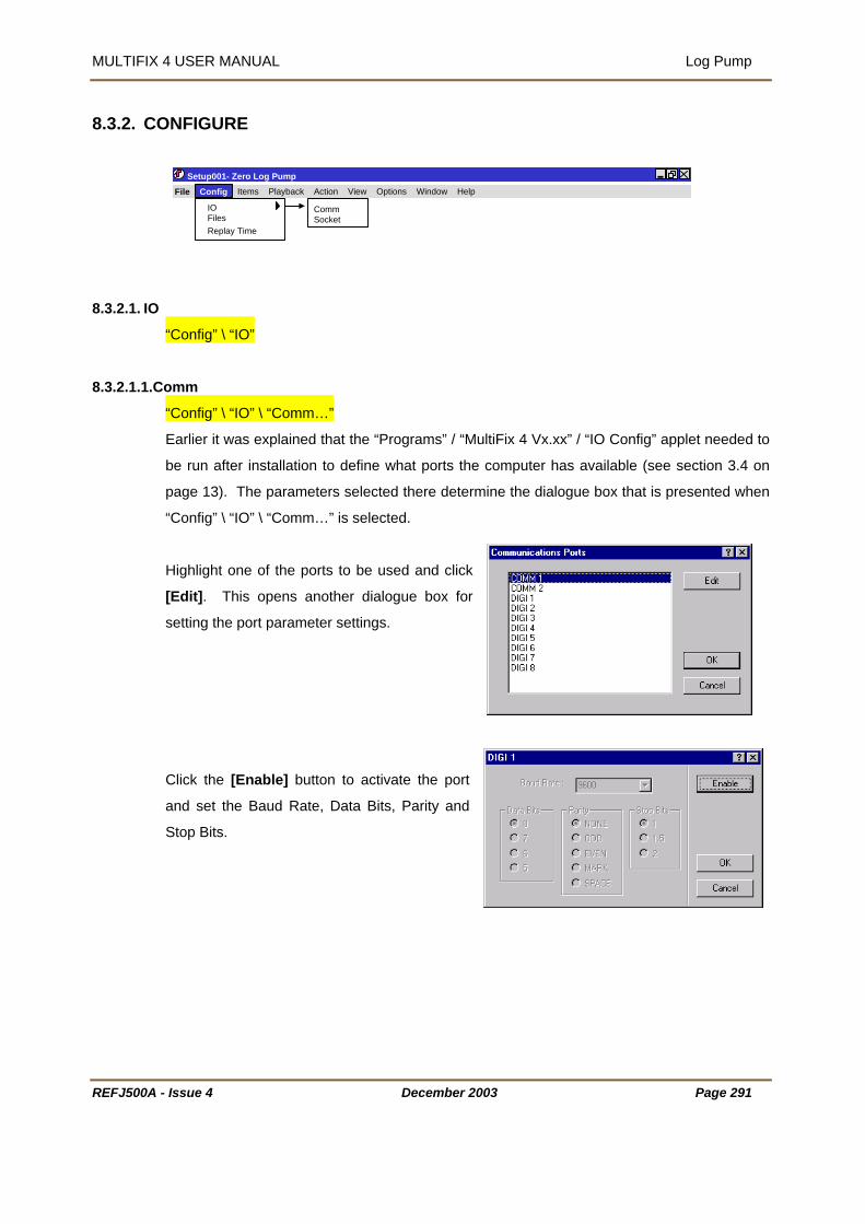
MULTIFIX 4 USER MANUAL Log Pump
8.3.2. CO
8.3.2.1. IO
NFIGURE
REFJ500A
Setup001- Zero Log Pump
8.3.2.1.1.C
- Issue 4 December 2003 Page 291
IO Comm
File Config Items Playback Action View Options Window Help
FilesReplay Time
Socket
“Config” \ “IO”
omm
“Config” \ “IO” \ “Comm…”
efine what ports the computer has available (see section 3.4 on
selected there determine the dialogue box that is presented when
selected.
ighlight one of the ports to be used and click
s another dialogue box for
setting the port parameter settings.
Click the [Enable] button to activate the port
and set the Baud Rate, Data Bits, Parity and
Stop Bits.
Earlier it was explained that the “Programs” / “MultiFix 4 Vx.xx” / “IO Config” applet needed to
be run after installation to d
page 13). The parameters
“Config” \ “IO” \ “Comm…” is
H
[Edit]. This open

MULTIFIX 4 USER MANUAL Log Pump
ets 8.3.2.1.2.Sock
“Config” \ “IO” \ “Socket…”
assumes each computer
as Transmission Control Protocol / Internet Protocol (TCP/IP) installed. Sockets have the
o or more programs can access the same data.
sfer data between programs running on different computers or between two
r more programs running on the same computer. (If a standalone (non-networked) computer
e data is to be shared between multiple programs running
apter network adapter must be installed).
he TCP/IP protocol is a family of protocols that allow Internet data communication. Included
protocols, the Transport Control Protocol (TCP) and the
ablishes sessions between a Server and however many
Server. There is continual presence checking and
r/Client pairs with messages always received in the order
ot have control of the number of Clients that access the
ich data is being presented. (It is often perceived that the Server provides data
and the Client receives data, but once the connection is established the link is two-way).
nt
ata becoming corrupted, see section on “Ribbons” 7.3.2.2. Broadcast datagrams cannot
For most situations where Local Area Networks are involved Server / Client TCP sockets are
oice Internet transport protocols.
To be able to distribute and receive data over a network via sockets
h
advantage over COM ports in that tw
Sockets can tran
o
running Windows NT is used and th
on that PC then the MS Loopback Ad
T
in that family are two transport layer
User Datagram Protocol (UDP).
The Transport Control Protocol est
Clients that are accessing that
acknowledging between each Serve
they were issued. A Server does n
socket on wh
The User Datagram Protocol does not have the end-to-end checking overhead of the TCP.
Instead packets of data are simply issued to the Internet in either broadcast mode, where any
networked computer on the LAN can receive them, or in addressed mode where the data
packets have headers specifying the addressees for whom the packets are intended. There
is no guarantee with this protocol that the messages will arrive in the order they were issued.
When setting up “Ribbons” to output datagrams a time interval can be specified to preve
d
pass routers linking Local Area Networks (LAN) unless specifically configured.
the best ch
REFJ500A - Issue 4 December 2003 Page 292

MULTIFIX 4 USER MANUAL Log Pump
8.3.2.1.2.1
ust know the IP address (or the
mputer and the port number the
.The Log Pump Application as a Client
For a Client to make contact with a Server, the operator m
network identification name - see below) of the Server co
Server is outputting the required data on.
First, in the “PC Names” table click
[New].
There are two possible ways of
defining the server PC.
If the numerical IP address is known,
enter a PC name in “Name:” and the IP
address in “Address:” and click
[Resolve>>]. Click [OK].
If the IP address is not known but the computer’s network identification name is, and if all
computers involved are aware of local naming services (WINS / DNS), then type in the
computer’s name in the “Address:” slot and click [Resolve>>]. Once the computer is found,
its IP address will appear as shown. If required, use [>>Literal] to transfer the name and
address to their named slots. Click [OK].
It is normal in a network for computers
to be allocated new IP addresses when
the PC is restarted. If the Client PC has
a numerical entry for the address and
the Server’s address has changed, it
REFJ500A - Issue 4 December 2003 Page 293

MULTIFIX 4 USER MANUAL Log Pump
will not be able to re-locate it. If the Client PC has the name of the Server PC in the address
slot, it will automatically search to re-locate the Server PC by name. Assuming it is found, the
Client PC will obtain the Server PC’s current address.
In the “Sockets” table click [New].
Check the “Client” radio button and select the ”PC Name:”
of the server.
Enter the number of the port on which the Server PC is
presenting the data. Change the socket’s default name if
required.
8.3.2.1.2.2.The Log Pump Application as a Server
ter to the PC table; the
rogram already knows the computer’s IP address. This
w called up by “View” “IO”\ \
ockets”, See Section 8.3.6.1.2 on page 306.
8.3.2.1.2.3
sses without the overheads associated
BROADCASTING
Log pump cannot give multiple addresses to packets of data so if information is to be made
available to more than one computer in datagrams it must be broadcast on a particular port.
A computer that is broadcasting on a port also listens to all data packets that are received on
that port.
If the Log Pump computer is to be a server then there is
no need to add the Soccer compu
p
can be seen in the windo
“S
In the “Sockets” table click [New]. Give the socket a
name and enter the Port number that the data will be
output on. Click [OK] to exit.
.Datagrams
It was explained in section 8.3.2.1.2.3 that the User Datagrams Protocol allows packets of
data to be broadcast or to be sent to specific addre
with the Transport Control Protocol.
REFJ500A - Issue 4 December 2003 Page 294

MULTIFIX 4 USER MANUAL Log Pump
DATAGRAMS TO/FROM A SPECIFIC PC
To transmit to or to receive from a specific computer, (which may itself be broadcasting), a PC
ere the port number and the PC are identified.
“Datagram” radio
Name:” list.
at the Internet address
f that PC should already have been identified. See
ection 8.3.2.1.2.1 on page 293 for an explanation of
dding PCs.
tered in the “PC Names:” table click [New] in the “Sockets” table.
,
nter the Port number and
e PC.
dit Socket Configuration dialogue now shows the connection(s).
must be set up with a datagram socket wh
To broadcast datagram packets, click the
button and select “Broadcast” from the “PC
To target one specific PC requires th
o
S
a
Once the PC has been en
Give the socket a name
e
in the “PC Name list
select th
Click [OK] to exit.
Having set up sockets, the E
REFJ500A - Issue 4 December 2003 Page 295

MULTIFIX 4 USER MANUAL Log Pump
8.3.2.2. Files
“Config” \ “Files”
This is used to select the logged files that are to be used for replay.
replayed click the
irectory” radio button.
particular *.zer files are to be
shift> or <Ctrl> to make multiple
d click the “Time” radio button. This activates the
entry of garbage in either the “Start” or “End” edit
t will not allow the edit control slot to be exited or
ialogue elements to be used. The @ symbol is the separator between date and time.
ate can be entered as 1st April 2003, 01 April 2003, 01 Apr 2003, or 01-4-2003. Time can be
Single figure hours do not need a preceding 0.
nce [OK] is used to exit the dialogue the “View” \ “Files” window will show the files that have
8.3.2.3. Replay Time
Use [Browse…] to locate the
directory containing the *.zer files
to be replayed.
If all the *.zer files in the directory
are to be
“D
If
selected, first click the “File” radio
button. Now highlight the *.zer
files that are to be replayed. Use
<
file selections. Now use the [>>]
to transfer them to the “Selected
Files” table.
If a particular time period is to be covere
“Specify Time” table. The program allows
control slots, but if an entry is incorrect i
other d
D
entered as 10:34:22, 10,34,22 or 10-34-22.
O
been selected for replay.
“Config” \ “Replay Time…”
This sets the period of time to be replayed.
REFJ500A - Issue 4 December 2003 Page 296

MULTIFIX 4 USER MANUAL Log Pump
This is non-operative in this version of Log Pump and in
ultiFix 4 version. The intention is to output a
me pulse such that when the data is fast-forwarded in
og Pump MultiFix 4 keeps up with the faster output rate.
t the moment it is expecting data paced at 1Hz.
the current M
ti
L
A
REFJ500A - Issue 4 December 2003 Page 297
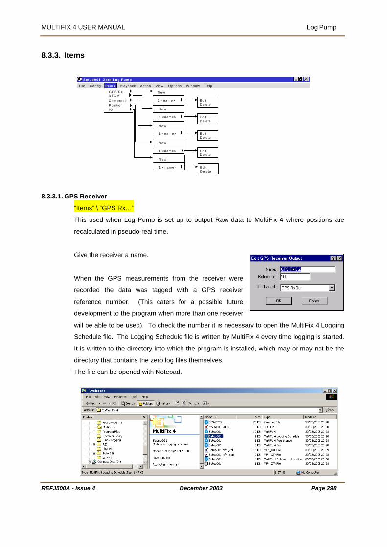
MULTIFIX 4 USER MANUAL Log Pump
8.3.3. Items
8.3.3.1. GP
Setup001- Zero Log Pum p
REFJ500A
S Receiver
<nam e>
F ile Config Item s P layback Action V iew O ptions W indow Help
G PS RxRTCMCom pressPositionIO
New
1 <nam e> EditDelete
New
EditDelete
New
1 <nam e> EditDelete
New
1 <nam e> EditDelete
New
1 <nam e> EditDelete
1
“Items” \ “GPS Rx…”
This used when Log Pump is set up to output Raw data to MultiFix 4 where positions are
recalculated in pseudo-real time.
Give the receiver a name.
When the GPS measurements from the receiver were
recorded the data was tagged with a GPS receiver
reference number. (This caters for a possible future
development to the program when more than one receiver
will be able to be used). To check the number it is necessary to open the MultiFix 4 Logging
Schedule file. The Logging Schedule file is written by MultiFix 4 every time logging is started.
It is written to the directory into which the program is installed, which may or may not be the
directory that contains the zero log files themselves.
The file can be opened with Notepad.
- Issue 4 December 2003 Page 298

MULTIFIX 4 USER MANUAL Log Pump
You see in the example that the “GPSMEAS” has a “LOGID” of 100.
elect the “IO Channel:” via which the
PS Measurements will be sent. This
hannel needs to be two-way because
ultiFix 4 will also be making requests
r almanac data and Log Pump will
8.3.3.2. RTCM
S
G
c
M
fo
need to respond to those requests.
“Items” \ “RTCM” \ “New”
Give the Output a name.
numbers.
As described in 8.3.3.1 above, enter the “LOGID” of the
RTCM.
Enter the “IO Channel” by which the RTCM data is to be output.
Decide whether a Carriage Return needs to be added to the end of each RTCM message.
(MultiFix 4 will use either).
If several RTCM sources have been recorded in the *.zer files and are to be replayed, set up
a different RTCM Output for each of the LOGID
Once an RTCM output has been established, it can be edited by using “Config” \ “RTCM” \
“<name>” \ “Edit…” or deleted by using “Config” \ “RTCM” \ “<name>” \ “Delete”
8.3.3.3. Compress
“Items” \ “Compress”
This function is not currently functional.
8.3.3.4. Position
“Items” \ “Position” \ New”
This is used for adding different position outputs.
REFJ500A - Issue 4 December 2003 Page 299

MULTIFIX 4 USER MANUAL Log Pump
When setting up logging in MultiFix 4 there are three options, “Raw”, “Position” and
aw+Position”. The earlier configuration of the GPS Receiver Output and the RTCM Output
was concerned with outputting Raw data to MultiFix 4
where positions can be recomputed in pseudo-real time.
Positions are not accepted by MultiFix 4 but they are by
Qual 2. Therefore the situation can arise where Log Pump
outputs Raw data to MultiFix 4, which then recomputes
positions from that Raw data and outputs those positions in ZeroLink format to Qual 2. At the
same time Log Pump outputs positions directly to Qual 2 and the two position solutions are
compared.
Give the output a name.
View the MultiFix 4 Logging Schedule file to see the LOGID of the positions. There will be a
different ID for each calculation set up in MultiF
example there was only one ca
aving decided what position is to be
O Channel” that is to carry the position
Use [OK] to exit the “New Position
Output” dialogue.
“R
ix 4 when the logging was taking place. In this
lculation (“Europe SPOT”).
H
read from the recording files, select the
“I
output and also decide what “Output ID:”
that position is to have. The “Output ID:”
must be in the range 00<->31. Do not
confuse this with the LOGID, it is not the
same.
Once a position output has been established, it can be edited by using “Config” \ “Position” \
“<name>” \ “Edit…” or deleted by using “Config” \ “Position” \ “<name>” \ “Delete”
8.3.3.5. IO
REFJ500A - Issue 4 December 2003 Page 300

MULTIFIX 4 USER MANUAL Log Pump
8.3.4. PLAYBACK
Setup001- Zero Log Pump
As see
has a t
“Play”
“FastF
“Pause
“Stop”
Stop re
REFJ500A - Issue
Play FastForwardPauseStop
File Config Items Playback Action View Options Window Help
n “Playback has four menu items, “Play”, “FastForward”, “Pause” and “Stop”. Each
oolbar button equivalent.
orward”
”
sets from the file being read to the start of the selected files.
4 December 2003 Page 301

MULTIFIX 4 USER MANUAL Log Pump
REFJ500A - I
8.3.5. ACTION
8.3.5.1. Rest
“A
O
re
c
Setup001- Zero Log Pump
ssue 4 December 2003 Page 302
art Sockets
ction” \ “Restart Sockets”
n occasion heavy network traffic may lock up TCP\IP socket ports. This option will
initialise all currently open sockets without having to restart the software or editing the
onfiguration files.
Restart Sockets
File Config Items Playback Action View Options Window Help
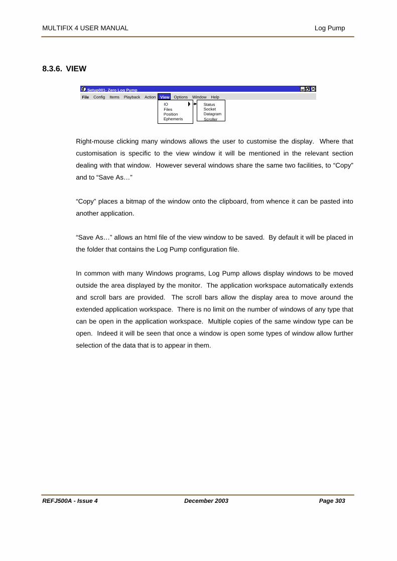
MULTIFIX 4 USER MANUAL Log Pump
8.3.6. VIEW
Setup001- Zero Log Pump
REFJ500A -
e display. Where that
ustomisation is specific to the view window it will be mentioned in the relevant section
asted into
nother application.
ave As…” allows an html file of the view window to be saved. By default it will be placed in
e folder that contains the Log Pump configuration file.
In common with many Windows programs, Log Pump allows display windows to be moved
outside the area displayed by the monitor. The application workspace automatically extends
and scroll bars are provided. The scroll bars allow the display area to move around the
extended application workspace. There is no limit on the number of windows of any type that
can be open in the application workspace. Multiple copies of the same window type can be
open. Indeed it will be seen that once a window is open some types of window allow further
selection of the data that is to appear in them.
Right-mouse clicking many windows allows the user to customise th
IOFiles
c
dealing with that window. However several windows share the same two facilities, to “Copy”
and to “Save As…”
“Copy” places a bitmap of the window onto the clipboard, from whence it can be p
a
“S
th
PositionEphemeris
StatusSocket
File Config Items Playback Action
Datagram
View Options Window Help
Scroller
Issue 4 December 2003 Page 303

MULTIFIX 4 USER MANUAL Log Pump
Fi
Display Area
RE
gure 21 tion Workspace
available space. Other windows
ontaining text will simply be cropped as the window size reduces. Windows containing
graphical information will resize down to a minimum and will then either crop the information
r will introduce scroll bars.
Windows Extending Beyond the Applica
Most windows can be resized by clicking and dragging the corners or sides. Some windows
that contain text will wrap the text message into the
Extended Application Workspace Horizontal Scroll Bar
Vertical Scroll Bar
Setup001- Log Pump File Config Items Playback Action View Options Window Help
Loading 12% Response 5% 1:33:29 pm UTC
c
o
FJ500A - Issue 4 December 2003 Page 304
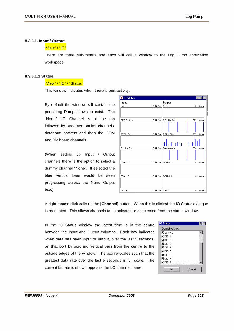
MULTIFIX 4 USER MANUAL Log Pump
REFJ500A - Issue 4 December 2003 Page 305
8.3.6.1. Input / Output
“View” \ “IO”
There are three sub-menus and each will call a window to the Log Pump application
workspace.
8.3.6.1.1.Status
“View” \ “IO” \ “Status”
This window indicates when there is port activity.
By default the window will contain the
ports Log Pump knows to exist. The
“None” I/O Channel is at the top
followed by streamed socket channels,
datagram sockets and then the COM
and Digiboard channels.
(When setting up Input / Output
channels there is the option to select a
dummy channel “None”. If selected the
blue vertical bars would be seen
progressing across the None Output
box.)
A right-mouse click calls up the [Channel] button. When this is clicked the IO Status dialogue
is presented. This allows channels to be selected or deselected from the status window.
In the IO Status window the latest time is in the centre
between the Input and Output columns. Each box indicates
when data has been input or output, over the last 5 seconds,
on that port by scrolling vertical bars from the centre to the
outside edges of the window. The box re-scales such that the
greatest data rate over the last 5 seconds is full scale. The
current bit rate is shown opposite the I/O channel name.

MULTIFIX 4 USER MANUAL Log Pump
REFJ500A - Issue 4 December 2003
8.3.6.1.2.Sockets
“View” \ “IO” \ “Sockets””
Client sockets can have three states,
Idle, Connecting and Connected.
Idle and Connecting will alternate while connection is trying to be established. There will also
be a time countdown to the next attempt to make contact.
Server sockets can have two states,
Idle and Listening.
The Idle status is almost immediately replaced by Listening.
8.3.6.1.3.Datagrams
“View” \ “IO” \ “Datagrams”
The Datagram Status window lists all Datagrams in use. The IP address indicates to which
PC a link is in place or if it is transmitting a broadcast message. The “Packets In” and
“Packets Out” window indicates if the datagram is working. If you are receiving data only the
“Packets In” will increase. If you are transmitting to n PCs the “Packets In” will increase at n
times the rate of the “Packets Out”.
8.3.6.1.4.Scroller
“View” \ “IO” \ “Scroller”
Scroller is able to display any of the inputs and outputs. When first opened the display
defaults to showing the link from the first GPS receiver in the configuration list.. To change to
another IO Channel or to change the scrolling options, click the right mouse button.
This calls up a menu box, which has “Device”, “Freeze”,
“Clear” and “Show” as shown opposite.
Device GPS MS750 Out
Page 306
FreezeClearShow
RTCM Out Position Out
Input Output Text Corrupt

MULTIFIX 4 USER MANUAL Log Pump
REFJ500A - Issue 4 December 2003 Page 307
If “Device” is highlighted there is a sub-menu which lists the different input / outputs. Top of
the list are the names given to the each of the GPS receivers. This is followed by the input
from PDS.
If “Freeze” is selected the current window display is held and frozen appears in the windows
title bar. Clicking “Freeze” again unfreezes the display. “Clear” will remove all information
from the current window.
“Show” brings up a new sub-menu with four options: “Input”, “Output”, Text” and “Corrupt”. A
tick next to the option indicates that the relevant information is currently displayed in the
Scroller window. These options may be toggled on/off by left clicking.
The text in the window is bottom justified and colour coded. Green indicates it has been
successfully decoded and passed all parity checks. Red indicates the data is corrupted.
Dark blue is reserved for outputs. When a message is received or sent successfully a black
text line is added as a label. Carriage return and line feed are shown in light grey.
Scroller windows use a lot of resources and should be closed when they are not required.
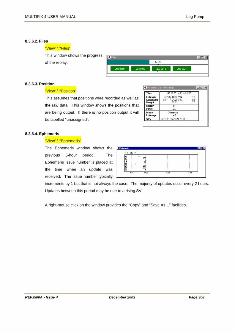
MULTIFIX 4 USER MANUAL Log Pump
8.3.6.2. Files
“View” \ “Files”
This window shows the progress
of the replay.
8.3.6.3. Position
“View” \ “Position”
data. This window shows the positions that
re being output. If there is no position output it will
be labelled “unassigned”.
8.3.6.4. Ephemeris
This assumes that positions were recorded as well as
the raw
a
“View” \ “Ephemeris”
he Ephemeris window shows the
previous 6-hour period. The
Ephemeris issue number is placed at
e time when an update was
ceived. The issue number typically
ments by 1 but that is not always the case. The majority of updates occur every 2 hours.
A right-mouse click on the window provides the “Copy” and “Save As…” facilities.
T
th
re
incre
Updates between this period may be due to a rising SV.
REFJ500A - Issue 4 December 2003 Page 308
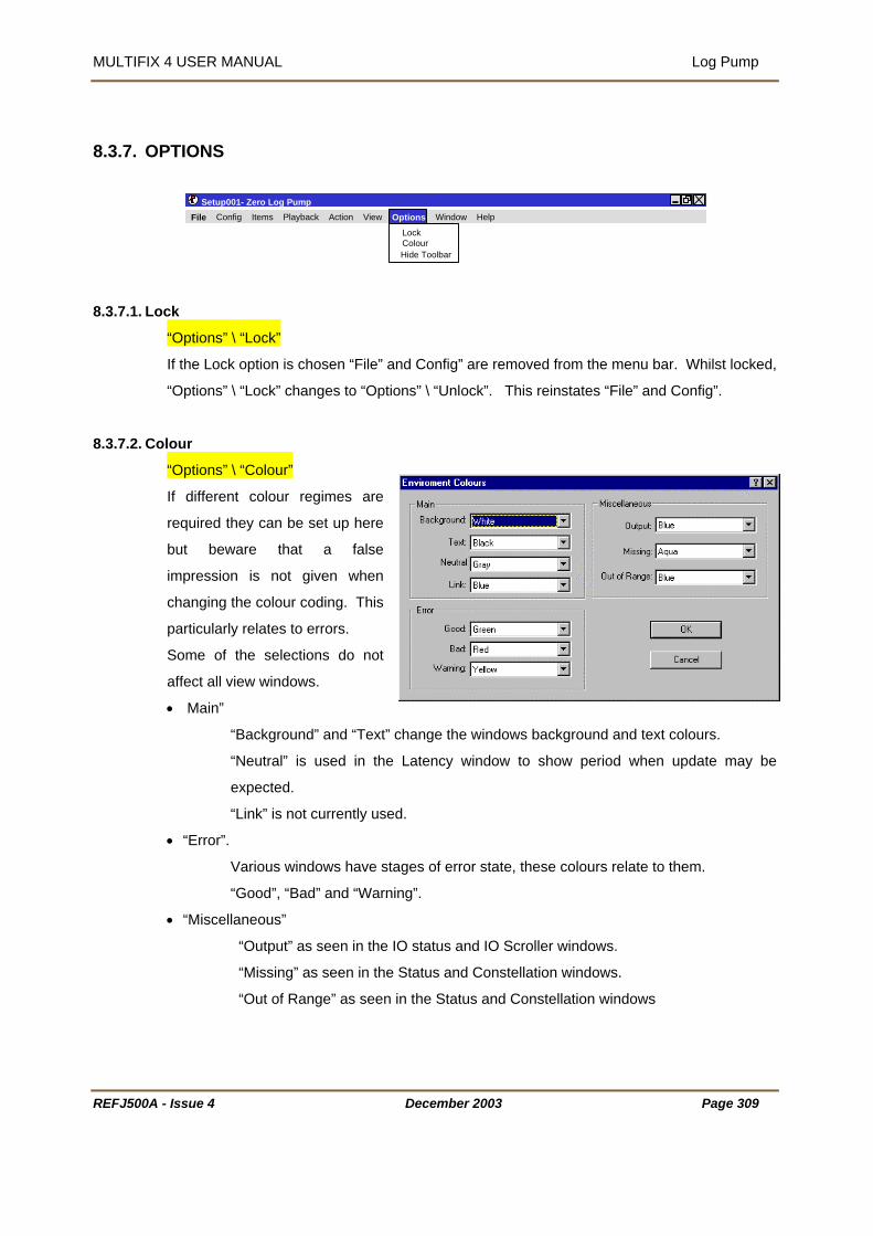
MULTIFIX 4 USER MANUAL Log Pump
REFJ500A - I
8.3.7. OPTIONS
8.3.7.1. Lock
“
If
“
8.3.7.2. Colo
“
If
r
b
im
c
p
S
a
•
•
•
Setup001- Zero Log Pump
ssue 4 December 2003 Page 309
Options” \ “Lock”
the Lock option is chosen “File” and Config” are removed from the menu bar. Whilst locked,
Options” \ “Lock” changes to “Options” \ “Unlock”. This reinstates “File” and Config”.
ur
Options” \ “Colour”
different colour regimes are
equired they can be set up here
ut beware that a false
pression is not given when
hanging the colour coding. This
articularly relates to errors.
ome of the selections do not
ffect all view windows.
Main”
“Background” and “Text” change the windows background and text colours.
“Neutral” is used in the Latency window to show period when update may be
expected.
“Link” is not currently used.
“Error”.
Various windows have stages of error state, these colours relate to them.
“Good”, “Bad” and “Warning”.
“Miscellaneous”
“Output” as seen in the IO status and IO Scroller windows.
“Missing” as seen in the Status and Constellation windows.
“Out of Range” as seen in the Status and Constellation windows
LockColour
File Config Items Playback Action View Options Window Help
Hide Toolbar
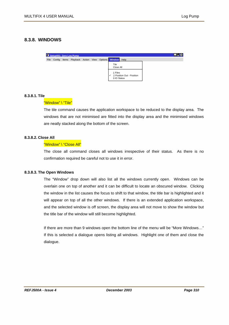
MULTIFIX 4 USER MANUAL Log Pump
REFJ500A
8.3.8. WINDOWS
8.3.8.1. Til
8.3.8.2. Clo
8.3.8.3. Th
Setup001- Zero Log Pump
- Issue 4 December 2003 Page 310
e
“Window” \ “Tile”
The tile command causes the application workspace to be reduced to the display area. The
windows that are not minimised are fitted into the display area and the minimised windows
are neatly stacked along the bottom of the screen.
se All
“Window” \ “Close All”
The close all command closes all windows irrespective of their status. As there is no
confirmation required be careful not to use it in error.
e Open Windows
The “Window” drop down will also list all the windows currently open. Windows can be
overlain one on top of another and it can be difficult to locate an obscured window. Clicking
the window in the list causes the focus to shift to that window, the title bar is highlighted and it
will appear on top of all the other windows. If there is an extended application workspace,
and the selected window is off screen, the display area will not move to show the window but
the title bar of the window will still become highlighted.
If there are more than 9 windows open the bottom line of the menu will be “More Windows…”
If this is selected a dialogue opens listing all windows. Highlight one of them and close the
dialogue.
TileClose All
1 Files 2 Position Out - Position
3 IO Status
File Config Items Playback Action View Options Window Help
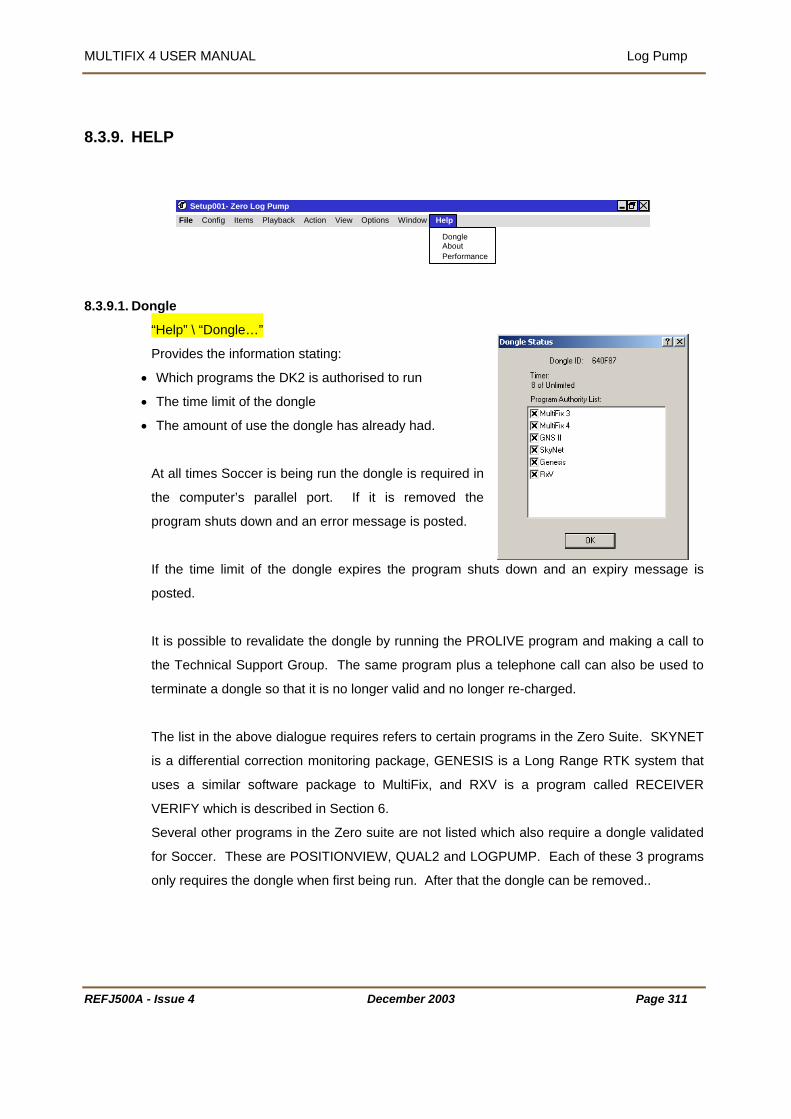
MULTIFIX 4 USER MANUAL Log Pump
REFJ500A - Is
8.3.9. HELP
8.3.9.1. Dong
“H
Pr
• W
• T
• T
At
the
pro
If
po
It i
the
ter
Th
is
us
VE
Se
for
on
Setup001- Zero Log Pump
sue 4 December 2003 Page 311
le
elp” \ “Dongle…”
ovides the information stating:
hich programs the DK2 is authorised to run
he time limit of the dongle
he amount of use the dongle has already had.
all times Soccer is being run the dongle is required in
computer’s parallel port. If it is removed the
gram shuts down and an error message is posted.
the time limit of the dongle expires the program shuts down and an expiry message is
sted.
s possible to revalidate the dongle by running the PROLIVE program and making a call to
Technical Support Group. The same program plus a telephone call can also be used to
minate a dongle so that it is no longer valid and no longer re-charged.
e list in the above dialogue requires refers to certain programs in the Zero Suite. SKYNET
a differential correction monitoring package, GENESIS is a Long Range RTK system that
es a similar software package to MultiFix, and RXV is a program called RECEIVER
RIFY which is described in Section 6.
veral other programs in the Zero suite are not listed which also require a dongle validated
Soccer. These are POSITIONVIEW, QUAL2 and LOGPUMP. Each of these 3 programs
ly requires the dongle when first being run. After that the dongle can be removed..
DongleAbout
File Config Items Playback Action View Options Window Help
Performance

MULTIFIX 4 USER MANUAL Log Pump
REFJ500A - Issue 4 December 2003 Page 312
8.3.9.2. Performance
“Help” \ “Performance”
process with the available
take into account other programs
below 50%, yellow between 50% and 75% and red when above
ses to be completed in an orderly fashion.
solution may lag. The demand on the processor
RTCM reference stations used in the
en in the bar at the bottom of the application
ime.
The Performance window shows
how the program is handling the
data acquisition and calculation
resources. The window does not
that are running simultaneously.
The graphs will be green
75%.
It is important there is enough time for all the proces
If there are too few resources the position
can be reduced by accessing only the data from the
computations, by having fewer computations and by closing windows.
The performance information can also be se
window next to the UTC T
8.3.9.3. About
“Help” \ “About…” provides the version number and release date
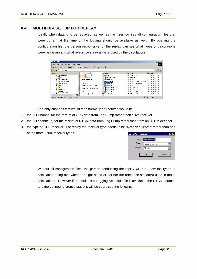
MULTIFIX 4 USER MANUAL Log Pump
8.4. MULTIFIX 4 SET UP FOR REPLAY Ideally when data is to be replayed, as well as the *.zer log files all configuration files that
ging should be available as well. By opening the
ble for the replay can see what types of calculations
were being run and what reference stations were used by the calculations.
were current at the time of the log
configuration file, the person responsi
uld then normally be required would be
1. the I/O Channel for the receipt of GPS data from Log Pump rather than a live receiver.
of RTCM data from Log Pump rather than from an RTCM decoder.
play the receiver type needs to be “Receiver Server” rather than one
Without all configuration files, the person conducting the replay will not know the types of
calculation being run, whether height aided or not nor the reference station(s) used in those
calculations. However if the MultiFix 4 Logging Schedule file is available, the RTCM sources
and the defined reference stations will be seen, see the following.
The only changes that wo
2. the I/O channel(s) for the receipt
3. the type of GPS receiver. For re
of the more usual receiver types.
REFJ500A - Issue 4 December 2003 Page 313
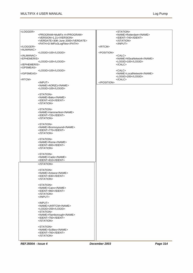
MULTIFIX 4 USER MANUAL Log Pump
<LOGGER> <PROGRAM>MultiFix 4</PROGRAM> <VERSION>1.21</VERSION> <VERDATE>30th June 2000</VERDATE> <PATH>D:\MFix3LogFiles</PATH> </LOGGER> <ALMANAC> <LOGID>100</LOGID> </ALMANAC> <EPHEMERIS> <LOGID>100</LOGID> </EPHEMERIS> <GPSMEAS> <LOGID 100</LOGID> ></GPSMEAS> <RTCM> <INPUT> <NAME>A E)</NAME> OR( <LOGID>100</LOGID> <STATION> <NAME>Baku</NAME> <IDENT>410</IDENT> </STATION> <STATION> <NAME>Hammerfest</NAME> <IDENT>720</IDENT> </STATION> <STATION> <NAME>Bronnoysund</NAME> <IDENT>7 /IDENT> 70< </STATION> <STATION> <NAME>Rome</NAME> <IDENT>800</IDENT> </STATION> <STATION> <NAME>Cadiz</NAME> <IDENT>810</IDENT> </STATION> <STATION> <NAME>Ankara</NAME> <IDENT>830</IDENT> </STATION> <STATION> <NAME>Cairo</NAME> <IDENT>960</IDENT> </STATION> </INPUT> <INPUT> <NAME>UKRTCM</NAME> <LOGID>200</LOGID> <STATION> <NAME>Flamborough</NAME> <IDENT>750</IDENT> </STATION> <STATION> <NAME>Scillies</NAME> <IDENT>760</IDENT> </STATION>
<STATION> <NAME>Rotterdam</NAME> <IDENT>740</IDENT> </STATION> </INPUT> </RTCM> <POSITION> <CALC> <NAME>NSeaNetwork</NAME> <LOGID>100</LOGID> </CALC> <CALC> <NAME>LocalNetwork</NAME> <LOGID>200</LOGID> </CALC> </POSITION>
REFJ500A - Issue 4 December 2003 Page 314

MULTIFIX 4 USER MANUAL Log Pump
Figure 22 Example MultiFix 4 Logging Schedule File
ata to MultiFix 4 there may be a
Almanac” to force an almanac update before new
ame control of MultiFix 4 as if it
were being run in real time with live data. Reference should be made to the MultiFix 4 section
for information on configuring and running the program online.
on file returned with the log files, it is
used to make a duplicate so that any configuration
changes made during the replay do not overwrite the configuration that was originally used.
Once Log Pump has started to replay files and is outputting d
requirement to use “Action” \ “Collect
positions will be formed. In all aspects the operator has the s
If MultiFix 4 has been set up using a configurati
recommended that “File” \ Save As…” is
REFJ500A - Issue 4 December 2003 Page 315

MULTIFIX 4 USER MANUAL Appendix A Data Output Strings
APPENDIX A - DATA OUTPUT STRINGS MEA GGA SENTENCE
444444444455555555556666666666777777777788 123456789012345678901234567890123456789012345678901234567890123456789012345678901
| | | | | $GPGGA,HHMMSS,DDMM.mmmmmm,N,DDDMM.mmmmmm,E,Q,NN,P.p,AA.aa,M,GG.gg,M,T.t,RFID*CS¬^
r
,............................ Comma
(up to 1 second old by time of output)
DDDMM.mmmmmm ...... Longitude at time of fix
Q............................ GPS Quality Indicator 0 = Fix invalid, 1 = non-diffGPS using C/A code, Fix valid,
NN.......................... Number of satellites used in Fix
.p........................ HDOP
AA.aa.................... Antenna Altitude at time of fix with respect to Geoid (+ve Antenna above Geoid)
M............................ Height units, M = Metres
GG.gg.................... Geoid / Spheroid separation (+ve Geoid above WGS84 spheroid)
T.t........................ Time in seconds since last RTCM type 1 or type 9 message
RFID...................... Differential reference station ID, if a network it will be 1001, 1002, etc.
*CS........................ Checksum
¬............................ Carriage Return
^............................ Line Feed
GGA (LDA) This is a modified version of the GGA string where the latency figure is divided by 5. This is
for interfacing to equipment that will not allow a latency figure in excess of 10 seconds. By
dividing the Latency, rather than fixing it, the system will still time out if a latency of 50
seconds is exceeded.
NB - This function should not be used on occasions that Selective Availability is enabled on
the GPS system.
N 111111111122222222223333333333
| | |
where
$ .............................. Start of Sentence Delimite
GP ............................ Talker Device Identifier
GGA........................ Sentence Formatter
HHMMSS .................. UTC Time of Fix,
DDMM.mmmmmm ........ Latitude at time of fix
N............................ Latitude Hemisphere Specifier, N or S
E............................ Longitude Hemisphere Specifier E or W
2 = DiffGPS using C/A code, Fix valid, 3 = GPS using P code, Fix valid
P
REFJ500A - Issue 4 December 2003 Page 316

MULTIFIX 4 USER MANUAL Appendix A Data Output Strings
NMEA GSA SENTENCE
123456789012345678901234567890123456789
$ .............................. Start of Sentence Delimiter
= Manual, forced to operate in 2D or 3D mode
lowed to automatically switch 2D/3D
e indicator 1 = Fix not available, 2 = 2D, 3 = 3D
solution*
p.p........................ PDOP
*cs ........................ Checksum
............................
ssible confusion caused by repetition of satellite ID numbers when
sing multiple systems, the following convention has been adopted:
111111111122222222223333333333
| | | $GPGSA,M,P,nn .. nn,p.p,h.h,v.v,*cs¬^
where
GP ............................ Talker Device Identifier
GSA........................ Sentence Formatter
,............................ Comma
M............................ Mode M
A = Automatic, al
P............................ Positioning mod
nn .. nn .......... ID numbers of satellites used in
h.h........................ HDOP
v.v........................ VDOP
¬ Carriage Return
^............................ Line Feed
*Satellite ID numbers. To avoid po
u
a) GPS satellites 1 – 32
b) Glonass 65 - 96
REFJ500A - Issue 4 December 2003 Page 317

MULTIFIX 4 USER MANUAL Appendix A Data Output Strings
NMEA GST SENTENCE 11111111112222222222333333333344444444445 2345678901234567890123456789012345678901234567890 | | | $GPGST,hhmmss.ss,r.r,s.s,d.d,o.o,l.l,m.m,a.a,*cs¬^
where
$ .............................. Start of Sentence Delimiter
GP ............................ Talker Device Identifier
GST........................ Sentence Formatter
,............................ Comma
HHMMSS.ss ............ UTC Time of Fix, (up to 1 second old by time of output)
r.r........................ RMS value of standard deviation of the range inputs to the navigation process
s.s........................ Standard deviation of semi-major axis of error ellipse (m)
d.d........................ Standard deviation of semi-minor axis of error ellipse (m)
o.o........................ Orientation of semi-major axis of error ellipse (degrees from True North)
l.l........................ Standard deviation of latitude error (m)
m.m........................ Standard deviation of longitude error (m)
a.a........................ Standard deviation of altitude error (m)
*cs ........................ Checksum
¬............................ Carriage Return
^............................ Line Feed
1
REFJ500A - Issue 4 December 2003 Page 318

MULTIFIX 4 USER MANUAL Appendix A Data Output Strings
NMEA GSV SENTENCE
44444444555555555 23456789012345678
$ ..............................
GSV........................
n............................
N..........................
s ........................
¬............................
^............................
1 Satellite
identical f
1. The s
1. 2 Satellite
numbers
a) GPS s
b) Glonas
1111111111222222222233333333334412345678901234567890123456789012345678901 | | | $GPGSV,n,m,tt,ss,ee,aaa,NN,............,ss,ee,aaa,NN,*cs¬^
where
GP ............................
,............................
m............................
tt..........................
The following section
ss..........................
ee..........................
aaa........................
N
*c
REFJ500A - Issue 4
SV1
Start of Sente
Sentence Fo
Total numbe
e
is
g
SNR
Checksum
Carriage Ret
Line Feed
information ma
ield formats. T
econd field iden
ID numbers.
when using mu
atellites 1 – 32
s 65 - 96
Talker Device
Comma
Message num
Total numb
repeated for
Satellite ID n
Elevation, de
Azimuth, de
SV2-3
nce Delimiter
rmatter
r of messages, 1
er, 1 to 91
r of satellites in v
umber2
s, 90° maxim
rees True, 000 to
urn
y require the tr
he first field spec
tifies the order o
To avoid possib
ltiple systems, the
Identifier
b
each satellite, to
gree
Decem
SV4
to 91
iew
r string
um
359
ansmission of multiple messages all containing
ifies the total number of messages, minimum value
f this message (message number), minimum value
le confusion caused by repetition of satellite ID
following convention has been adopted:
a maximum of 4 pe
ber 2003 Page 319

MULTIFIX 4 USER MANUAL Appendix A Data Output Strings
NMEA VTG SENTENCE 1111111111222222222233333333 1234567890123456789012345678901234567 | | | $GPVTG,CCC.c,T,,,SSS.s,N,VVV.v,K*cs¬^
$ .............................. Start of Sentence Delimiter
und
round
und
K............................ Kilometres per Hour
r Ground Magnetic if MultiFix 4 new anything about magnetic
North.
where
GP ............................ Talker Device Identifier
VTG........................ Sentence Formatter
,............................ Comma
CCC.c.................... Course Over Gro
T............................ True
SSS.s.................... Speed Over G
N............................ Knots
VVV.v.................... Speed Over Gro
*cs........................ Checksum
¬............................ Carriage Return
^............................ Line Feed
The null fields would contain Course Ove
REFJ500A - Issue 4 December 2003 Page 320

MULTIFIX 4 USER MANUAL Appendix A Data Output Strings
NMEA GLL SENTENCE
123456789012345678901234567890123456789012345678901234
r
r
GLL........................ Sentence Formatter
S............................ Latitude Hemisphere N or S
or W
Q............................ Status Flag, A = Valid, V = Not Valid
see note below)
A = Stand Alone, D = Differential, E = Estimated,
lid
*cs........................ Checksum
^............................ Line Feed
Note: - Between the NMEA 0183 Standard versions 2.01 and 2.30 the GLL sentence has had an extra
ioning System Mode
dicator. The 2.3 Standard says em Mode Indicator
andard and does not include the Position System Mode Indicator.
111111111122222222223333333333444444444455555
| | | | | $GPGLL,DDMM.mmmmmm,S,DDDMM.mmmmmm,W,HHMMSS.ss,Q,M*cs¬^
where
$ .............................. Start of Sentence Delimite
GP ............................ Talker Device Identifie
,............................ Comma
DDMM.mmmmmm ........ Latitude
DDDMM.mmmmmm ...... Longitude
W............................ Longitude Hemisphere E
HHMMSS .................. UTC Time of the position
M............................ Position System Mode Indicator (
M = Manual Input, S = Simulated, N = Not va
¬............................ Carriage Return
field added after the Status Flag and before the checksum, this is called the Posit
In 0 that both the Status Flag and Positioning Syst
fields must not be null fields.
MultiFix 4 complies with the 2.01 St
REFJ500A - Issue 4 December 2003 Page 321

MULTIFIX 4 USER MANUAL Appendix A Data Output Strings
RTK SENTENCE Kinematic computations supported by the MultiFix 4.
Not to be used until Real Time
REFJ500A - Issue 4 December 2003 Page 322

MULTIFIX 4 USER MANUAL Appendix A Data Output Strings
REFJ500A - Issue 4 December 2003 Page 323
NMEA ZDA SENTENCE 111111111122222222223333333333 123456789012345678901234567890123456789 | | | $GPZDA,HHMMSS.ss,DD,MM,YYYY,±hh,mm*cs¬^
where
$ .............................. Start of Sentence Delimiter
GP ............................ Talker Device Identifier
ZDA........................ Sentence Formatter
,............................ Comma
HHMMSS.ss ............ UTC Time
DD.......................... Day in Month
MM.......................... Month in Year
YYYY...................... Year
±hh........................ Local Time Zone hours offset, always zeroes
mm.......................... Local Time Zone minutes offset, always zeroes
*cs ........................ Checksum
¬............................ Carriage Return
^............................ Line Feed

MULTIFIX 4 USER MANUAL Appendix A Data Output Strings
REFJ500A - Issue 4 December 2003 Page 324
NMEA RMC SENTENCE 1111111111222222222233333333334444444444555555555566666666667 1234567890123456789012345678901234567890123456789012345678901234567890 | | | | | | | $GPRMC,HHMMSS.ss,Q,DDMM.mmmmm,N,DDDMM.mmmmm,W,SS.s,CCC.c,DDMMYY,,*cs¬^
where
$ .............................. Start of Sentence Delimiter
GP ............................ Talker Device Identifier
RMC........................ Sentence Formatter
,............................ Comma
HHMMSS.ss ............ UTC Time of fix
Q............................ Status flag, A = valid, V = invalid
DDMM.mmmmm .......... Latitude
N............................ Latitude Hemisphere, North or South
DDDMM.mmmmm ........ Longitude
W............................ Longitude Hemisphere, East or West
SS.s...................... Speed Over ground in knots
CCC.c.................... Course Over Ground, True
DDMMYY .................. Date
*cs........................ Checksum
¬............................ Carriage Return
^............................ Line Feed
The null fields refer to the Magnetic Variation

MULTIFIX 4 USER MANUAL Appendix A Data Output Strings
NMEA UKOOA / IMCA DP SENTENCE
1111111111222222222233333333334444444444555555555566666666667777777777888 1234567890123456789012345678901234567890123456789012345678901234567890123456789012
| S*CS¬^
here
Comma
HHMMSS .................. UTC Time of Fix, (up to 1 second old by time of output)
f fix
N............................ Latitude Hemisphere Specifier, N or S
me of fix
phere Specifier E or W
r (see table below)
lites used in Fix
/Geoid.
ct to MSL/Geoid
tres
e WGS84 spheroid)
nds since last RTCM type 1 or type 9 message
ed Link
DGPS Satellite -based link
otes – DGPS indicator
| | | | | | | $DPGGA,HHMMSS.SS,DDMM.mmmm,N,DDDMM.mmmm,E,Q,NN,P.p,UAA.aa,M,UGG.gg,M,T.t,DGP
w
$ .............................. Start of Sentence Delimiter
DP ............................ Talker Device Identifier
GGA........................ Sentence Formatter
,............................
DDMM.mmmm ............ Latitude at time o
DDDMM.mmmm .......... Longitude at ti
E............................ Longitude Hemis
Q............................ DGPS Quality Indicato
NN.......................... Number of satel
P.p........................ HDOP
U ........................... Sign of Altitude above or below MSL
AA.aa.................... Antenna Altitude at time of fix with respe
M............................ Height units, M = Me
U ........................... Sign of Geoidal separation (+ve Geoid abov
GG.gg.................... Geoid / Spheroid separation
T.t........................ Time in seco
DGPS...................... DGPS system identifier, DGPR = DGPS Radio-Bas
DPGI =
*CS........................ Checksum
¬............................ Carriage Return
^............................ Line Feed
N is fixed to DPGI.
REFJ500A - Issue 4 December 2003 Page 325

MULTIFIX 4 USER MANUAL Appendix A Data Output Strings
DGPS Quality Indicator
QI
D Status of Solution Precision Comment
0 Failed solution N/A -
1 Uncorrected N/A Solution obtained but no differential
2 Corrected but no redundancy N/A Minimum DGPS Solution
3 Corrected Position;
Redundancy of 1
Poor Poor Dilution of Precision (DOP)/ Geometry
4 Corrected Position;
Redundancy of 1
<10m Adequate DOP / Geometry
5 Corrected Position;
Redundancy > 1
<10m Ability to reject Outlier;
Gradual improvement in geometry/DOP
6 Corrected Position;
Redundancy > 1
<10m Ability to reject Outlier;
Gradual improvement in geometry/DOP
7 Corrected Position;
Redundancy > 1
<4m Ability to reject Outlier;
Gradual improvement in geometry/DOP
8 Corrected Position;
Redundancy > 1
<2m Ability to reject Outlier;
Gradual improvement in geometry/DOP
9 Corrected Position;
Redundancy > 1
<0.5m Ability to reject Outlier;
Gradual improvement in geometry/DOP
REFJ500A - Issue 4 December 2003 Page 326

MULTIFIX 4 USER MANUAL Appendix A Data Output Strings
REFJ500A - Issue 4 December 2003 Page 327
DNAVN OUTPUT FORMAT 11111111112222222222333333333344444444445555555555666666666677777777778 12345678901234567890123456789012345678901234567890123456789012345678901234567890 | | | | | | | | [DJJJMMDDYYHHMMSS.sLL.lDN523516.65E0014404.22+057.4CCC.cSSS.sXXXYYYPP.pHH.hMRDQq 11111111111111111111111111111111111111111111111 888888888999999999900000000001111111111222222222233333333334444444 123456789012345678901234567890123456789012345678901234567890123456 | | | | | | mmssN##SNREF ##SNREF //nsref]cs ¬^
where
[............................ Start Character
D .............................. Day of Week (0-6, 0 is Sunday)
JJJ .......................... Julian Day
MMDDYY.................... Date
HHMMSS.s ............... UTC Time of Record
LL.l........................ Time of Record minus Time of Fix in seconds
D .............................. Datum Flag (0=WGS 72, 1=WGS 84, 2= NAD 84, 3 = NAD 83, 4-9= reserved)
N .............................. Latitude Hemisphere Specifier (N or S)
523516.65 ............. Latitude (DDMMSS.ss)
E .............................. Longitude Hemisphere Specifier
0014404.22 ........... Longitude (DDDMMSS.ss)
+057.4.................... Altitude with respect to Ellipsoid (±m)
CCC.c...................... Course Over Ground (deg True)
SSS.s...................... Speed Over Ground (kts)
XXX .......................... 3D Position Error (m, 1-σ)
YYY .......................... 2D Position Error (m, 1-σ)
PP.p........................ PDOP (invalid if only 3 SV’s are being tracked)
HH.h........................ HDOP
M .............................. Operating Mode (0=No Solution, 1=4SV,2=3SV+Alt Aid, 3=3SV+Clk Aid, 4=2SV+Alt Aid
+Clk Aid, 5=All in View)
R .............................. Receiver Code (0-6=Reserved, 7=C/A, L1 only, Carrier Aided, 8-9=Reserved)
D .............................. Receiver Dynamics (0=Static, 1=Low……9=High)
Q .............................. Position Quality (0=Poor, 9=Good)
q .............................. Differential Quality (0=No Corrections, 1=Poor…..9=Good)
mmss........................ Time Since Last Correction
N .............................. Number of SV’s Tracked

MULTIFIX 4 USER MANUAL Appendix A Data Output Strings
REFJ500A - Issue 4 December 2003 Page 328
## ............................ first SV PRN
SN ............................ first SV SNR (Trimble Units)
RE ............................ first SV Range Residual Error (m)
F .............................. first SV Status Flag (Bit 0=Elevation Flag, 0=SV is above mask,
•
•............................... ##SNREF repeated for each SV
•
nn ............................ last SV PRN (This will be determined by the number of satellites being tracked)
nn ............................ last SV SNR (Trimble Units)
nnn .......................... last SV Range Residual Error (m)
n .............................. last SV Status Flag
] ............................... Stop Character
cs ............................ Checksum (The hexadecimal representation of the modulo-256 sum of the characters
from “[“ to “]” inclusive
¬ .............................. Carriage Return
^ .............................. Line Feed
DNAVN – NAUTIS MODIFICATION
The Nautis Modified DNAV out put is in the same format to the standard DNAV, other than that a maximum
number of satellites (10) are fixed within the output string. This allows a Nautis navigation system to accept DNAV
strings that would normally contain 10 or more SVs.

MULTIFIX 4 USER MANUAL Appendix A Data Output Strings
TRIMBLE OUTPUT FORMAT 11111111112222222222333333333344444444445555555555666666666677777 12345678901234567890123456789012345678901234567890123456789012345678901234 | | | | | | | [ID Day 294 DD-MMM-YY HH:MM:SSF52:35.2785N 001:44.0637E ±0094 2.4 ClkOff 1111111111111111111111111111111111 7777788888888889999999990000000000111111111122222222223333 5678901234568901234567890123456789012345678901234567890123 | | | | | | ±VVV.vv SSS.ss HHH.h +0.0000E+00 0000 3 nn,nn,nn,nn,nn]¬^
Where
.................. Start Character
tion Number
DD-MMM-YY ............ Date (e.g. 13-Apr-00)
F............................ Differentially Corrected Flag (d = Corrected, Space = Uncorrected)
N............................ Latitude Hemisphere Indicator (N or S)
ngitude
isphere Indicator (E or W)
4 spheroid
econds
omponent of Velocity
HHH.h.................... Heading of Vessel (deg. True)
quency Offset from GPS
0000 3 nn, ,nn If 6 or less satellites then four zeros followed by the minimum number of
he fix and then the PRN numbers of satellites used in the
position fix
ellite then the PRN’s of Satellites used in Position Fix
]............................ Stop Character
[..........
ID.......................... Station Identifica
Day........................ Day of Week
294........................ Julian Day
HH:MM:SS .............. UTC Time
52:35.2785 .......... WGS 84 Latitude (DD:MM.mmmm)
001:44.0637 ........ WGS 84 Lo
E............................ Longitude Hem
±0094.................... Height of Antenna Referenced to WGS 8
02.4...................... PDOP
ClkOff .................. Calculated Receiver Clock Offset in Nanos
±VVV.vv ................ Vertical Component of Velocity
SSS.ss .................. Horizontal C
+0.0000E+00 ........ Receiver Clock Fre
satellites required by t
nn, ... ,nn ........ If more than 6 sat
¬............................ Carriage Return
^............................ Line Feed
REFJ500A - Issue 4 December 2003 Page 329

MULTIFIX 4 USER MANUAL Appendix A Data Output Strings
REFJ500A - Issue 4 December 2003 Page 330
ZEROLINK This is the data exchange format for all the Zero suite programs.
It is a binary (non-ASCII) format.

MULTIFIX 4 USER MANUAL Appendix A Data Output Strings
REFJ500A - Issue 4 December 2003 Page 331
FUGRO UKOOA OUTPUT FORMAT 111111111122222222223333333333444444444455555555556666666666777777777788888 123456789012345678901234567890123456789012345678901234567890123456789012345678901234 | | | | | | | | [LTV**HHMMSSsDDMMYYAAaGDDMMSSsssNDDDMMSSsssEHHHHh^MXXxYYyZZZPPpQQqRRrUUuFKKkLLlCCcBB 111111111111111111111111111111 888889999999999000000000011111111112222222222 567890123456789012345678901234567890123456789 | | | | NNnn .. .. nnTTFFR refstncdes optionalcs¬^
Where
[............................ Start Character
L............................ Length of Message
T............................ Message Type Identifier
V............................ Message Version Identifier
*............................ Message Dependant Byte
*............................ Message Dependant Byte
HHMMSSs ................ UTC Time of Fix
DDMMYY .................. Date of Fix (DDMMYY)
AAa ....................... Age of Data
G............................ Datum Indicator (W=WGS 84, Z=Other Datum, ?=Datum Not Known)
DDMMSSsss ............ Latitude
N............................ Latitude Hemisphere Specifier (N or S)
DDDMMSSsss .......... Longitude
E............................ Longitude Hemisphere Specifier (E or W)
HHHh...................... Height (HHHH.h) -999.9 to 9999.9 in m
^............................ Height Reference Indicator (S=Spheroidal Height, M=Height above MSL ie.
Orthometric)
M............................ Mode (H=Height Aided, 3=3D Solution, ?=Unknown)
XXx........................ 95% Error Ellipse semi-major axis (m)
YYy........................ 95% Error Ellipse semi-minor axis (m)
ZZZ........................ 95% Error Ellipse Max Direction (°)
PPp........................ 95% Latitude s d / Precision Value (m)
QQq........................ 95% Longitude s d / Precision Value (m)
RRr........................ 95% Height s d / Precision Value (m)
UUu........................ Unit Variance
F............................ F Test (P=Pass, F=Fail)
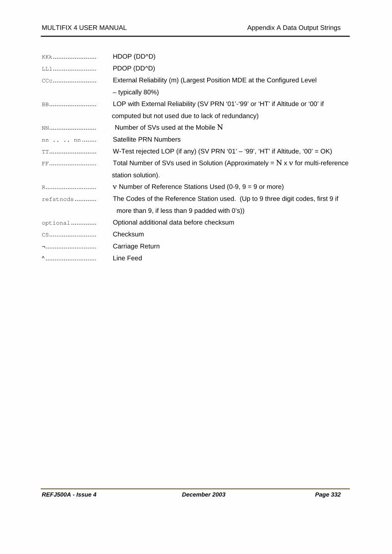
MULTIFIX 4 USER MANUAL Appendix A Data Output Strings
REFJ500A - Issue 4 December 2003 Page 332
KKk........................ HDOP (DD^D)
LLl........................ PDOP (DD^D)
CCc........................ External Reliability (m) (Largest Position MDE at the Configured Level
– typically 80%)
BB.......................... LOP with External Reliability (SV PRN ‘01’-‘99’ or ‘HT’ if Altitude or ‘00’ if
computed but not used due to lack of redundancy)
NN.......................... Number of SVs used at the Mobile Ν
nn .. .. nn ........ Satellite PRN Numbers
TT.......................... W-Test rejected LOP (if any) (SV PRN ‘01’ – ‘99’, ‘HT’ if Altitude, ‘00’ = OK)
FF.......................... Total Number of SVs used in Solution (Approximately = Ν x ν for multi-reference
station solution).
R............................ ν Number of Reference Stations Used (0-9, 9 = 9 or more)
refstncds ............ The Codes of the Reference Station used. (Up to 9 three digit codes, first 9 if
more than 9, if less than 9 padded with 0’s))
optional .............. Optional additional data before checksum
CS.......................... Checksum
¬............................ Carriage Return
^ ............................ Line Feed

MULTIFIX 4 USER MANUAL Appendix A Data Output Strings
GECO UKOOA OUTPUT FORMAT 1111111111222222222233333333334444444444555555555566666666667777777777888 1234567890123456789012345678901234567890123456789012345678901234567890123456789012 | | | | | | | | [0101NPMulti 1.32WWWWTTTTTTT.tAA.a_DD_MM.mmmmmN_DDD_MM.mmmmmEAAA.aHHH.hVVV.vUU.uuu 111111111111111111111111111111111111111111111
11112222222222333333333344444 67890123456789012345678901234 | | | ATREF SatNos RefStnIds ]¬^
.......... System Name/ Version (Should identify system and software version)
WWW
............................ Latitude Hemisphere Identifier (N or S)
mmmmm ...... Longitude
tifier (E or W)
GS 84)
VVV.v.................... VDOP
XX.xxx .................. Variance Latitude
t/Long
ZZ.zzz .................. Variance Longitude
t
##.### .................. External Reliability
SAT........................ Number of Satellites Used
REF........................ Number of Reference Stations Used For This Fix
888888899999999990000000000111111345678901234567890123456789012345 | | | XX.xxxYY.yyyZZ.zzz@@.@@@##.###FFS
where
[............................ Start Character
01.......................... Record Identifier
01.......................... Format Version
NP.......................... Nav Point Number
............................ Space _
Multi 1.32
...................... GPS Week Number since January 6th 1980 W
TTTTTTT.t ............ Seconds in GPS week (GPS time)
...................... Age of Fix AA.a
_DD_MM.mmmmm ...... Latitude
N
_DD_MM.
E............................ Longitude Hemisphere Iden
AAA.a.................... Spheroidal Height (above W
HHH.h.................... HDOP
UU.uuu .................. Unit Variance
YY.yyy .................. Covariance La
@@.@@@ .................. Variance Heigh
FF.......................... Fix Status (0=No or Bad Fix, 1=Alt. Aiding, 2=Alt Hold, 3=3D Fix)
REFJ500A - Issue 4 December 2003 Page 333

MULTIFIX 4 USER MANUAL Appendix A Data Output Strings
REFJ500A - Issue 4 December 2003 Page 334
SatNos .................. PRN Numbers of the satellites used in fix
RefStnIds ............ ID’s of the Reference Stations used in the fix
] ............................ End Character
¬............................ Carriage Return
^............................ Line Feed
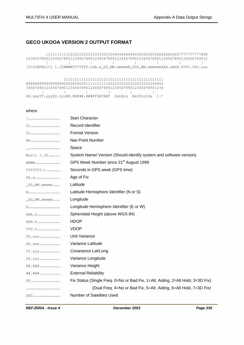
MULTIFIX 4 USER MANUAL Appendix A Data Output Strings
REFJ500A - Issue 4 December 2003 Page 335
GECO UKOOA VERSION 2 OUTPUT FORMAT 1111111111222222222233333333334444444444555555555566666666667777777777888 1234567890123456789012345678901234567890123456789012345678901234567890123456789012 | | | | | | | | [0101NPMulti 1.32WWWWTTTTTTT.tAA.a_DD_MM.mmmmmN_DDD_MM.mmmmmEAAA.aHHH.hVVV.vUU.uuu 111111111111111111111111111111111111111111111 88888889999999999000000000011111111112222222222333333333344444 34567890123456789012345678901234567890123456789012345678901234 | | | | | | XX.xxxYY.yyyZZ.zzz@@.@@@##.###FFSATREF SatNos RefStnIds ]¬^
where
[............................ Start Character
01.......................... Record Identifier
01.......................... Format Version
NP.......................... Nav Point Number
_............................ Space
Multi 1.32 .......... System Name/ Version (Should identify system and software version)
WWWW...................... GPS Week Number since 21 P
stP August 1999
TTTTTTT.t ............ Seconds in GPS week (GPS time)
AA.a...................... Age of Fix
_DD_MM.mmmmm ...... Latitude
N............................ Latitude Hemisphere Identifier (N or S)
_DD_MM.mmmmm ...... Longitude
E............................ Longitude Hemisphere Identifier (E or W)
AAA.a.................... Spheroidal Height (above WGS 84)
HHH.h.................... HDOP
VVV.v.................... VDOP
UU.uuu .................. Unit Variance
XX.xxx .................. Variance Latitude
YY.yyy .................. Covariance Lat/Long
ZZ.zzz .................. Variance Longitude
@@.@@@ .................. Variance Height
##.### .................. External Reliability
FF.......................... Fix Status (Single Freq. 0=No or Bad Fix, 1=Alt. Aiding, 2=Alt Hold, 3=3D Fix)
.............................. (Dual Freq. 4=No or Bad Fix, 5=Alt. Aiding, 6=Alt Hold, 7=3D Fix)
SAT........................ Number of Satellites Used

MULTIFIX 4 USER MANUAL Appendix A Data Output Strings
REFJ500A - Issue 4 December 2003 Page 336
REF........................ Number of Reference Stations Used For This Fix
SatNos .................. PRN Numbers of the satellites used in fix
RefStnIds ............ ID’s of the Reference Stations used in the fix
] ............................ End Character
¬............................ Carriage Return
^............................ Line Feed

MULTIFIX 4 USER MANUAL Appendix A Data Output Strings
FUGRO XP EXPANDED OUTPUT FORMAT 111111111122222222223333333333444444444455555555556666666666777777777788888 123456789012345678901234567890123456789012345678901234567890123456789012345678901234 | | | | | | | | **XHHMMSS.sDDMMYYAA.aDDMMSS.ssssNDDDMMSS.ssssEHHHH.hhHHHH.hhNNN.nnEEE.eeC.ccccHHH.hh 11111 11111111188888999999999900000 00001111156789012345678901234 678901234 | | XXX.xxYYY.yyZZZLL.lHH .hPPP.pM
ly generated if a standard differential calculation is used, either as a
XP Mode = 2, 3, 4, 5 or 6)
1111111111111111111111111111 111222222222233333333334444444444555555555566666666667777 789012345678901234567890123456789012345678901234567890123 | | | | | | UU.uuFRR.rrrrBBNNnn .. .. nnRRCCiiiX .. .. iiiX*XX¬^
XP Only - this section is only generated if a true XP calculation is used (i.e. XP Mode = 0 or 1) 1111111111111111111111111111111111111111111111111111111111111111111111 1111222222222233333333334444444444555555555566666666667777777777888888 6678901234567890123456789012345678901234567890123456789012345678901234 | | | | | | UU.uuFRR.rrrrBBNNnn .. .. nnUU.uuIRR.rrrrBBNNnn .. .. nniii*XX¬^
Where
*............................ Message Dependant Byte
*............................ Message Dependant Byte
X............................ Hexadecimal identifier
HHMMSS.s .............. UTC Time of Fix
DDMMYY .................. Date of Fix (DDMMYY)
AA.a ..................... Age of Data
DDMMSS.ssss ........ Latitude
N............................ Latitude Hemisphere Specifier (N or S)
DDDMMSS.ssss ...... Longitude
E............................ Longitude Hemisphere Specifier (E or W)
HHHH.hh ................ Height above mean sea level (HHHH.hh) -999.99 to 9999.99 in m
HHHH.hh ................ Height of geoid (mean sea level) above WGS84 ellipsoid (HHHH.hh) -999.99 to
9999.99 in m
1 1 0 1 5 5
H M
Differential Only – this section is on
standard calculation or an XP back-up (i.e. 11111111111111111111111111111116
REFJ500A - Issue 4 December 2003 Page 337

MULTIFIX 4 USER MANUAL Appendix A Data Output Strings
REFJ500A - Issue 4 December 2003 Page 338
NNN.nn .................. 95% Latitude Standard Deviation / Precision Value (m)
EEE.ee .................. 95% Longitude Standard Deviation / Precision Value (m)
C.cccc .................. Correlation Coefficient - 1 to +1
HHH.hh .................. 95% Height Standard Deviation / Precision Value (m)
XXX.xx .................. 95% Error Ellipse semi-major axis (m)
YYY.yy .................. 95% Error Ellipse semi-minor axis (m)
ZZZ........................ 95% Error Ellipse Max Direction with respect to North (°)
LL.l...................... Latency (s)
HHH.h.................... HDOP (DDD^D)
PPP.p.................... PDOP (DDD^D)
M............................ Calculation Mode 0 – No Solution 1 – XP 2 – Dual Frequency Diff. 3D 3 – Dual Frequency Diff. 2D 4 – Single Frequency Diff. 3D 5 – Single Frequency Diff. 2D 6 – Standalone
M............................ XP Mode 0 – No Solution 1 – XP 2 – Converging to XP 3 – Backup Solution 1 4 – Converging to Backup Solution 1 5 – Backup Solution 2
6 – Converging to Backup Solution 2
DIFFERENTIAL ONLY – this section is only generated if a standard differential calculation is used, either
as a standard calculation or an XP back-up (i.e. XP Mode = 2, 3, 4, 5 or 6)
UU.uu.................... Unit Variance
F............................ F Test (P=Pass, F=Fail)
RR.rrrr ................ External Reliability (m) (Largest Position MDE at the Configured Level
– typically 80%)
BB.......................... PRN with highest External Reliability value
NN.......................... Number of SVs used in the calculation
nn .. .. nn ........ Satellite PRN Numbers
RR.......................... Number of Reference Stations Used (0-99)
CC.......................... Number of Reference Stations in Configuration (0-99)
iii........................ The ID Code of Reference Station 1. (three digit code)
X............................ Number of SVs from Reference Station 1. (hexadecimal character) . . .

MULTIFIX 4 USER MANUAL Appendix A Data Output Strings
REFJ500A - Issue 4 December 2003 Page 339
iii........................ The ID Code of Reference Station n. (three digit code)
X............................ Number of SVs from Reference Station n. (hexadecimal character)
*XX........................ Checksum
¬............................ Carriage Return
^............................ Line Feed
XP ONLY - this section is only generated if a true XP calculation is used (i.e. XP Mode = 0 or 1)
UU.uu.................... Unit Variance, delta calculation
F............................ F Test (P=Pass, F=Fail), delta calculation
RR.rrrr ................ External Reliability (m) (Largest Position MDE at the Configured Level
– typically 80%), delta calculation
BB.......................... PRN with highest External Reliability value
NN.......................... Number of SVs used in the delta calculation
nn .. .. nn ........ Satellite PRN Numbers in the delta calculation
UU.uu.................... Unit Variance, filter calculation
I............................ Innovation Check (P=Pass, F=Fail), filter calculation
RR.rrrr ................ External Reliability (m) (Largest Position MDE at the Configured Level
- typically 80%), filter calculation
BB.......................... PRN with highest External Reliability value
NN.......................... Number of SVs used in the filter calculation
nn .. .. nn ........ Satellite PRN Numbers in the filter calculation
iii........................ XP SkyFix Beam ID
*XX........................ Checksum
¬............................ Carriage Return
^............................ Line Feed

MULTIFIX 4 USER MANUAL Appendix A Data Output Strings
REFJ500A - Issue 4 December 2003 Page 340
FUGRO XP CONCISE OUTPUT FORMAT 111111111122222222223333333333444444444455555555556666666666777777777788888 123456789012345678901234567890123456789012345678901234567890123456789012345678901234 | | | | | | | | **XHHMMSS.sDDMMYYAA.aDDMMSS.ssssNDDDMMSS.ssssEHHHH.hhHHHH.hhHHH.hhXXX.xxYYY.yyZZZUU. 11111111111111111111 88888999999999900000000001111111111 56789012345678901234567890123456789 | | | uuFRR.rrrrLL.lHHH.hPPP.pNNMMRR*XX¬^
Where
*............................ Message Dependant Byte
*............................ Message Dependant Byte
X............................ Hexadecimal identifier
HHMMSS.s .............. UTC Time of Fix
DDMMYY .................. Date of Fix (DDMMYY)
AA.a ..................... Age of Data
DDMMSS.ssss ........ Latitude
N............................ Latitude Hemisphere Specifier (N or S)
DDDMMSS.ssss ...... Longitude
E............................ Longitude Hemisphere Specifier (E or W)
HHHH.hh ................ Height above mean sea level (HHHH.hh) -999.99 to 9999.99 in m
HHHH.hh ................ Height of geoid (mean sea level) above WGS84 ellipsoid (HHHH.hh) -999.99 to
9999.99 in m
HHH.hh .................. 95% Height Standard Deviation / Precision Value (m)
XXX.xx .................. 95% Error Ellipse semi-major axis (m)
YYY.yy .................. 95% Error Ellipse semi-minor axis (m)
ZZZ........................ 95% Error Ellipse Max Direction with respect to North (°)
UU.uu.................... Unit Variance, filter calculation
F............................ F-Test for Backup solution or Innovation Check for XP solution (P=Pass, F=Fail)
RR.rrrr ................ External Reliability (m) (Largest Position MDE at the Configured Level
- typically 80%), filter calculation
LL.l...................... Latency (s)
HHH.h.................... HDOP (DDD^D)
PPP.p.................... PDOP (DDD^D)
NN.......................... Number of SVs used in the calculation
M............................ Calculation Mode 0 – No Solution

MULTIFIX 4 USER MANUAL Appendix A Data Output Strings
REFJ500A - Issue 4 December 2003 Page 341
1 – XP 2 – Dual Frequency Diff. 3D 3 – Dual Frequency Diff. 2D 4 – Single Frequency Diff. 3D 5 – Single Frequency Diff. 2D 6 – Standalone
M............................ XP Mode 0 – No Solution 1 – XP 2 – Converging to XP 3 – Backup Solution 1 4 – Converging to Backup Solution 1 5 – Backup Solution 2
6 – Converging to Backup Solution 2
RR.......................... Number of Reference Stations Used (0-99)
*XX........................ Checksum
¬............................ Carriage Return
^............................ Line Feed

MULTIFIX 4 USER MANUAL Appendix A Data Output Strings
UTM / SYLEDIS 1111111111222222222233333333334 1234567890123456789012345678901234567890 | | | |
_Y±NNNNNNN.n_X±EEEEEEE.e_Ffff_Qqqqqqqq¬^
.............................. Y co-ordinate Identifier
.............. 000 = Diff Corrected, 001 = Stand Alone
he Eastings and Northings will be Transverse Mercator co-ordinates, the projection grid is defined when
where
_ .............................. Space
Y
±NNNNNNN.n ........... Northings to 0.1 of a metre
X............................ X co-ordinate Identifier
±EEEEEEE.e .......... Eastings to 0.1 of a metre
F............................ Differential Flag Identifier
fff..........
Q............................ Quality Flag Identifier
qqqqqqq ................ Not Implemented, always 0000000
¬............................ Carriage Return
^............................ Line Feed
T
setting up the output.
REFJ500A - Issue 4 December 2003 Page 342

MULTIFIX 4 USER MANUAL Appendix A Data Output Strings
UTM/GEM 80 DP 1 111111111122222222223333333 23456789012345678901234567890123456 | | | _Y±NNNNNNN.n_X±EEEEEEE.e_Q_qDRMLPM¬^
where
_ .............................. Space, ASCII character 32
Y .............................. Y co-ordinate identifier, (ASCII character 89)
s when necessary)
ASCII character 88)
when necessary)
ess n
:DRMS (metres) nnn
PM .................... Quality :LPME (metres) nnn
rriage Return
............................ Line Feed
ates, the projection grid is defined when
± .............................. Sign + or -
NNNNNNN.n ............ Northings (leading zero
X............................ X co-ordinate identifier, (
EEEEEEE.e ............ Eastings (leading zeros
Q............................ Quality Field Identifier
q............................ Quality : Filtering Strictn
DRM ...................... Quality
L
¬............................ Ca
^
The Eastings and Northings will be Transverse Mercator co-ordin
setting up the output.
REFJ500A - Issue 4 December 2003 Page 343

MULTIFIX 4 USER MANUAL Appendix A Data Output Strings
DGPS_IS This output is under development and not fully implemented.
REFJ500A - Issue 4 December 2003 Page 344

MULTIFIX 4 USER MANUAL Appendix B Understanding Scintillation
REFJ500A - Issue 4 December 2003 Page 345
A
B
APPENDIX B – UNDERSTANDING SCINTILLATION Recent increases in the level of solar activity have had noticeable effects on GPS receiver equipment.
Effects can be categorised into two distinct effects:
a) Ionospheric delay
b) Scintillation
Ionospheric Delay is sometimes called the gradient effect. It is caused by the GPS signal slowing as it
passes through the ionosphere. The signals are slowed at different rates at different locations,
depending on the path taken through the earth’s atmosphere. When a DGPS system is in use, the path
of the signal through the atmosphere from the individual satellites will be different to the reference station
and to the user. Therefore, standard pseudorange corrections, that only model the atmospheric
differences, may not fully remove the range error.
This error is removed by using dual frequency observations, such as with SkyFix premier. The second
frequency allows the magnitude of the delay to be measured at both the reference station and the users
location. The error can then be removed.
Scintillation is a different phenomenon. The GPS signal is itself damaged in the ionosphere leading to
failure of the GPS receiver to maintain a lock on the satellite. This same problem can occur to the
satellite based RTCM delivery links, be they SPOT or Inmarsat, as discussed later.
The net effect is that instabilities are introduced into the position calculation, potentially each time a
satellite is removed or reintroduced into the solution. This is best illustrated by looking at an example.
In the MultiFix screen shot on the right (taken from “View” \ “Calculation” “Residuals” the individual lines
of position from each SV can be visualised in 2D. The users position is derived by a weighted least
squares adjustment to fit within all the lines of position. This is in the centre of the display and is marked
by the letter A.
Now, consider a scenario where SV 20 is suddenly
removed from the calculation. The correct solution
for a least squares adjustment is then close to point
B.
The size of the resulting position jump is obviously
dependant on both the size of the “cocked hat” (and
resulting error ellipse) and the effect of the missing
SV on that cocked hat. There are many factors to
consider when reviewing the residuals including but
not restricted to:
• Number of SVs in view,
• Geometry of SVs
• Elevation of individual SVs

MULTIFIX 4 USER MANUAL Appendix B Understanding Scintillation
REFJ500A - Issue 4 December 2003 Page 346
During periods of high ionospheric activity this cocked hat will be large (the solution will be divergent) due
to ionospheric delay, the effects will therefore be greater. This effect will be reduced if dual frequency
observations are used, as the cocked hat will once again be small.
We have seen here the potential effect of scintillation on a single SV. In reality, scintillation will affect
more than one SV at a time, although it rarely affects all SVs at the same time. With the removal of each
SV, the stability of the solution is reduced, thereby increasing the effect of subsequent satellite losses.
Detecting Scintillation
Ionospheric conditions are at their worst around the geomagnetic equator. Therefore, if you are in the
Southern Hemisphere satellites to the North are the most likely to be affected, conversely in the Northern
Hemisphere satellites to the South are most effected. If you are close to the equator all satellites may be
affected.
There are a number of ways of detecting scintillation within MultiFix. The first sign is within the Signal to
Noise Ratios (SNR). These can be viewed in MultiFix 4 under “View” \“GPS” \“Measurements”. High
variations in SNR are indicative of scintillation. Note you will also see low fluctuating SNRs with low
elevation satellites or other forms of
interference.
The adjacent screen shot is of SNRs under
normal conditions. The scale bar on each
measurement is the variation over the past
100 records.
This second plot is taken from a period of
scintillation and demonstrates the scale of the
variation typically seen.
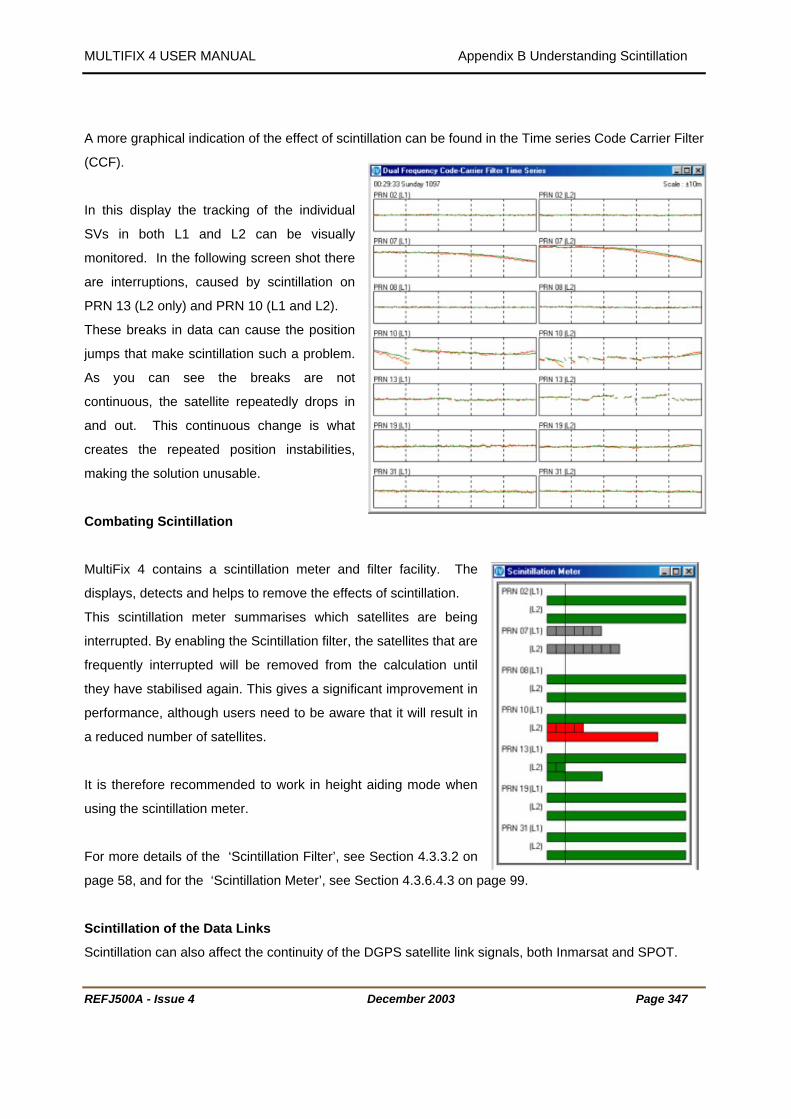
MULTIFIX 4 USER MANUAL Appendix B Understanding Scintillation
REFJ500A - Issue 4 December 2003 Page 347
A more graphical indication of the effect of scintillation can be found in the Time series Code Carrier Filter
(CCF).
In this display the tracking of the individual
SVs in both L1 and L2 can be visually
monitored. In the following screen shot there
are interruptions, caused by scintillation on
PRN 13 (L2 only) and PRN 10 (L1 and L2).
These breaks in data can cause the position
jumps that make scintillation such a problem.
As you can see the breaks are not
continuous, the satellite repeatedly drops in
and out. This continuous change is what
creates the repeated position instabilities,
making the solution unusable.
Combating Scintillation
MultiFix 4 contains a scintillation meter and filter facility. The
displays, detects and helps to remove the effects of scintillation.
This scintillation meter summarises which satellites are being
interrupted. By enabling the Scintillation filter, the satellites that are
frequently interrupted will be removed from the calculation until
they have stabilised again. This gives a significant improvement in
performance, although users need to be aware that it will result in
a reduced number of satellites.
It is therefore recommended to work in height aiding mode when
using the scintillation meter.
For more details of the ‘Scintillation Filter’, see Section 4.3.3.2 on
page 58, and for the ‘Scintillation Meter’, see Section 4.3.6.4.3 on page 99.
Scintillation of the Data Links
Scintillation can also affect the continuity of the DGPS satellite link signals, both Inmarsat and SPOT.
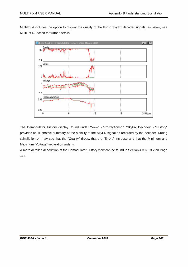
MULTIFIX 4 USER MANUAL Appendix B Understanding Scintillation
REFJ500A - Issue 4 December 2003 Page 348
MultiFix 4 includes the option to display the quality of the Fugro SkyFix decoder signals, as below, see
MultiFix 4 Section for further details.
The Demodulator History display, found under “View” \ “Corrections” \ “SkyFix Decoder” \ “History”
provides an illustrative summary of the stability of the SkyFix signal as recorded by the decoder. During
scintillation on may see that the “Quality” drops, that the “Errors” increase and that the Minimum and
Maximum “Voltage” separation widens.
A more detailed description of the Demodulator History view can be found in Section 4.3.6.5.3.2 on Page
118.
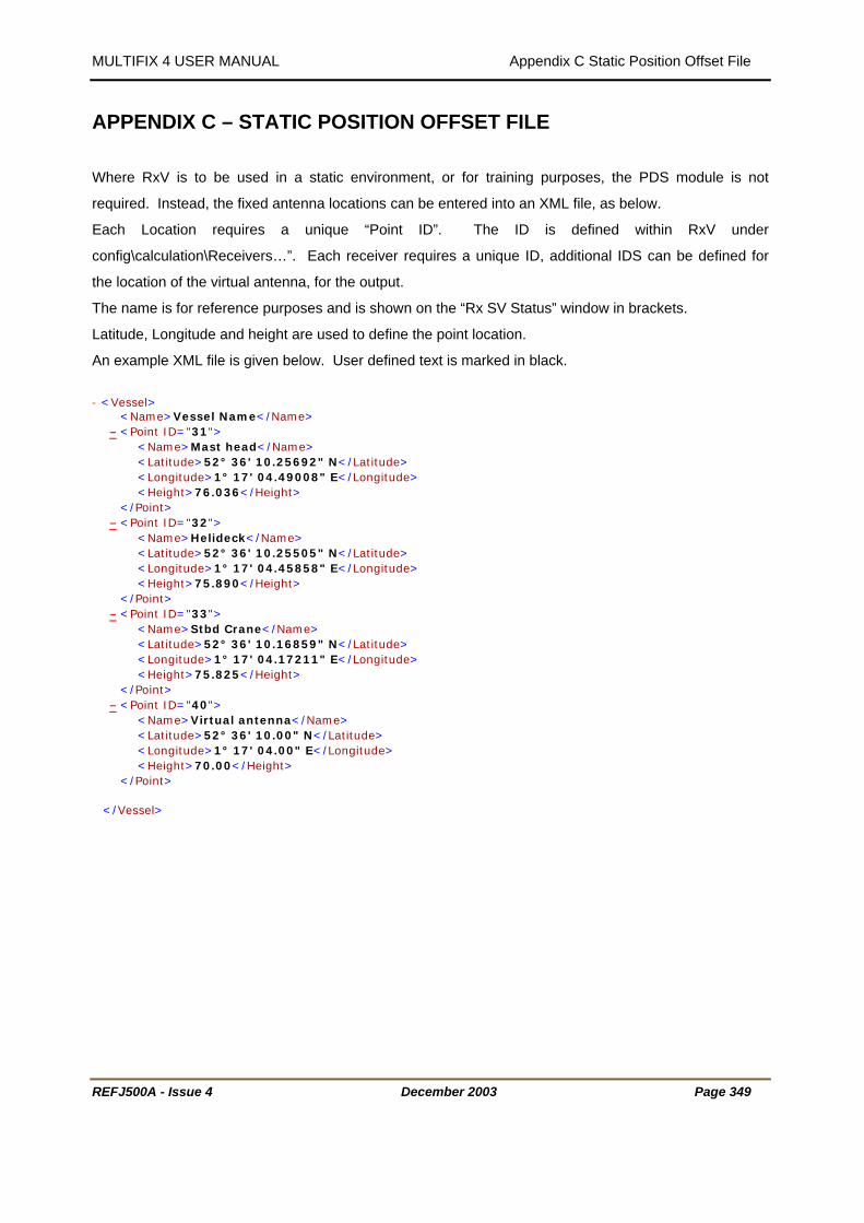
MULTIFIX 4 USER MANUAL Appendix C Static Position Offset File
REFJ500A - Issue 4 December 2003 Page 349
APPENDIX C – STATIC POSITION OFFSET FILE
Where RxV is to be used in a static environment, or for training purposes, the PDS module is not
required. Instead, the fixed antenna locations can be entered into an XML file, as below.
Each Location requires a unique “Point ID”. The ID is defined within RxV under
config\calculation\Receivers…”. Each receiver requires a unique ID, additional IDS can be defined for
the location of the virtual antenna, for the output.
The name is for reference purposes and is shown on the “Rx SV Status” window in brackets.
Latitude, Longitude and height are used to define the point location.
An example XML file is given below. User defined text is marked in black.
T- < TTVesselTT> T
T T T< TTNameTT> TTVessel NameTT</TTNameTT> T HTU- UTH T< TTPoint IDTT="T31 T"> T
T T T< TTNameTT> TTMast head TT</TTNameTT> T T T T< TTLatitudeTT> TT52° 36' 10.25692" N TT</TTLatitudeTT> T T T T< TTLongitudeTT> TT1° 17' 04.49008" E TT</TTLongitudeTT> T T T T< TTHeightTT> TT76.036 TT</TTHeightTT> T
T T T</TTPointTT> T
HTU- UTH T< TTPoint IDTT="T32 T"> T
T T T< TTNameTT> TTHelideckTT</TTNameTT> T T T T< TTLatitudeTT> TT52° 36' 10.25505" N TT</TTLatitudeTT> T T T T< TTLongitudeTT> TT1° 17' 04.45858" E TT</TTLongitudeTT> T T T T< TTHeightTT> TT75.890 TT</TTHeightTT> T
T T T</TTPointTT> T
HTU- UTH T< TTPoint IDTT="T33 T"> T
T T T< TTNameTT> TTStbd CraneTT</TTNameTT> T T T T< TTLatitudeTT> TT52° 36' 10.16859" N TT</TTLatitudeTT> T T T T< TTLongitudeTT> TT1° 17' 04.17211" E TT</TTLongitudeTT> T T T T< TTHeightTT> TT75.825 TT</TTHeightTT> T
T T T</TTPointTT> HTU- UTH < TPoint IDT="40">
T T < TNameT> TVirtual antennaT</TNameT> T T < TLatitudeT> T52° 36' 10.00" N T</TLatitudeT> T T < TLongitudeT> T1° 17' 04.00" E T</TLongitudeT> T T < THeightT> T70.00 T</THeightT>
T T </TPointT>
T T </TVesselT>