Embed Size (px)
Citation preview

Multichannel STM-1 Port Adapter Installation and Configuration Product Number: PA-MC-STM-1SMI(=), PA-MC-STM-1MM(=)Platforms Supported: Catalyst 6000 Family Switches and Cisco 7600 Series Internet Routers with FlexWAN Module, Cisco 7200 VXR Routers, Cisco 7201 Router, Cisco 7301 Router, Cisco 7304 PCI Port Adapter Carrier Card in the Cisco 7304 Router, Cisco 7401ASR Router, and VIP in the Cisco 7500 Series Routers
Americas HeadquartersCisco Systems, Inc.170 West Tasman DriveSan Jose, CA 95134-1706 USAhttp://www.cisco.comTel: 408 526-4000
800 553-NETS (6387)Fax: 408 527-0883
Text Part Number: OL-2746-11

THE SPECIFICATIONS AND INFORMATION REGARDING THE PRODUCTS IN THIS MANUAL ARE SUBJECT TO CHANGE WITHOUT NOTICE. ALL STATEMENTS, INFORMATION, AND RECOMMENDATIONS IN THIS MANUAL ARE BELIEVED TO BE ACCURATE BUT ARE PRESENTED WITHOUT WARRANTY OF ANY KIND, EXPRESS OR IMPLIED. USERS MUST TAKE FULL RESPONSIBILITY FOR THEIR APPLICATION OF ANY PRODUCTS.
THE SOFTWARE LICENSE AND LIMITED WARRANTY FOR THE ACCOMPANYING PRODUCT ARE SET FORTH IN THE INFORMATION PACKET THAT SHIPPED WITH THE PRODUCT AND ARE INCORPORATED HEREIN BY THIS REFERENCE. IF YOU ARE UNABLE TO LOCATE THE SOFTWARE LICENSE OR LIMITED WARRANTY, CONTACT YOUR CISCO REPRESENTATIVE FOR A COPY.
The following information is for FCC compliance of Class A devices: This equipment has been tested and found to comply with the limits for a Class A digital device, pursuant to part 15 of the FCC rules. These limits are designed to provide reasonable protection against harmful interference when the equipment is operated in a commercial environment. This equipment generates, uses, and can radiate radio-frequency energy and, if not installed and used in accordance with the instruction manual, may cause harmful interference to radio communications. Operation of this equipment in a residential area is likely to cause harmful interference, in which case users will be required to correct the interference at their own expense.
The following information is for FCC compliance of Class B devices: The equipment described in this manual generates and may radiate radio-frequency energy. If it is not installed in accordance with Cisco’s installation instructions, it may cause interference with radio and television reception. This equipment has been tested and found to comply with the limits for a Class B digital device in accordance with the specifications in part 15 of the FCC rules. These specifications are designed to provide reasonable protection against such interference in a residential installation. However, there is no guarantee that interference will not occur in a particular installation.
Modifying the equipment without Cisco’s written authorization may result in the equipment no longer complying with FCC requirements for Class A or Class B digital devices. In that event, your right to use the equipment may be limited by FCC regulations, and you may be required to correct any interference to radio or television communications at your own expense.
You can determine whether your equipment is causing interference by turning it off. If the interference stops, it was probably caused by the Cisco equipment or one of its peripheral devices. If the equipment causes interference to radio or television reception, try to correct the interference by using one or more of the following measures:
• Turn the television or radio antenna until the interference stops.
• Move the equipment to one side or the other of the television or radio.
• Move the equipment farther away from the television or radio.
• Plug the equipment into an outlet that is on a different circuit from the television or radio. (That is, make certain the equipment and the television or radio are on circuits controlled by different circuit breakers or fuses.)
Modifications to this product not authorized by Cisco Systems, Inc. could void the FCC approval and negate your authority to operate the product.
The Cisco implementation of TCP header compression is an adaptation of a program developed by the University of California, Berkeley (UCB) as part of UCB’s public domain version of the UNIX operating system. All rights reserved. Copyright © 1981, Regents of the University of California.
NOTWITHSTANDING ANY OTHER WARRANTY HEREIN, ALL DOCUMENT FILES AND SOFTWARE OF THESE SUPPLIERS ARE PROVIDED “AS IS” WITH ALL FAULTS. CISCO AND THE ABOVE-NAMED SUPPLIERS DISCLAIM ALL WARRANTIES, EXPRESSED OR IMPLIED, INCLUDING, WITHOUT LIMITATION, THOSE OF MERCHANTABILITY, FITNESS FOR A PARTICULAR PURPOSE AND NONINFRINGEMENT OR ARISING FROM A COURSE OF DEALING, USAGE, OR TRADE PRACTICE.
IN NO EVENT SHALL CISCO OR ITS SUPPLIERS BE LIABLE FOR ANY INDIRECT, SPECIAL, CONSEQUENTIAL, OR INCIDENTAL DAMAGES, INCLUDING, WITHOUT LIMITATION, LOST PROFITS OR LOSS OR DAMAGE TO DATA ARISING OUT OF THE USE OR INABILITY TO USE THIS MANUAL, EVEN IF CISCO OR ITS SUPPLIERS HAVE BEEN ADVISED OF THE POSSIBILITY OF SUCH DAMAGES.
Multichannel STM-1 Port Adapter Installation and ConfigurationCopyright © 2007 Cisco Systems, Inc. All rights reserved.
CCVP, the Cisco Logo, and the Cisco Square Bridge logo are trademarks of Cisco Systems, Inc.; Changing the Way We Work, Live, Play, and Learn is a service mark of Cisco Systems, Inc.; and Access Registrar, Aironet, BPX, Catalyst, CCDA, CCDP, CCIE, CCIP, CCNA, CCNP, CCSP, Cisco, the Cisco Certified Internetwork Expert logo, Cisco IOS, Cisco Press, Cisco Systems, Cisco Systems Capital, the Cisco Systems logo, Cisco Unity, Enterprise/Solver, EtherChannel, EtherFast, EtherSwitch, Fast Step, Follow Me Browsing, FormShare, GigaDrive, HomeLink, Internet Quotient, IOS, iPhone, IP/TV, iQ Expertise, the iQ logo, iQ Net Readiness Scorecard, iQuick Study, LightStream, Linksys, MeetingPlace, MGX, Networking Academy, Network Registrar, Packet, PIX, ProConnect, RateMUX, ScriptShare, SlideCast, SMARTnet, StackWise, The Fastest Way to Increase Your Internet Quotient, and TransPath are registered trademarks of Cisco Systems, Inc. and/or its affiliates in the United States and certain other countries.
All other trademarks mentioned in this document or Website are the property of their respective owners. The use of the word partner does not imply a partnership relationship between Cisco and any other company. (0704R)

OL-2746-11
C O N T E N T S
Preface vii
Document Revision History vii
Objectives viii
Organization viii
Related Documentation ix
Obtaining Documentation, Obtaining Support, and Security Guidelines xi
C H A P T E R 1 Overview 1-1
Port Adapter Overview 1-1
SDH Overview 1-3
PA-MC-STM-1 Multiplexing Hierarchy 1-4
Features 1-5
PA-MC-STM-1 Optical Fiber Specifications 1-5
LEDs 1-6
Cables, Connectors, and Pinouts 1-7
Management Information Base 1-8
Port Adapter Slot Locations on the Supported Platforms 1-9
Catalyst 6000 Family Switches and Cisco 7600 Series Routers with FlexWAN Module Slot Numbering 1-9
Cisco 7200 VXR Routers Slot Numbering 1-11
Cisco 7200 VXR Routers with the Port Adapter Jacket Card Slot Numbering 1-12
Cisco 7201 Router Slot Numbering 1-12
Cisco 7301 Router Slot Numbering 1-13
Cisco 7304 PCI Port Adapter Carrier Card Slot Numbering 1-13
Cisco 7401ASR Router Slot Numbering 1-14
Cisco 7500 Series Routers VIP Slot Numbering 1-15
Identifying Interface Addresses 1-16
Catalyst 6000 Family Switches and Cisco 7600 Series Routers with FlexWAN Module Interface Addresses 1-18
Cisco 7200 VXR Routers Interface Addresses 1-18
Cisco 7200 VXR Routers with the Port Adapter Jacket Card Interface Addresses 1-19
Cisco 7201 Routers Interface Addresses 1-19
iiiMultichannel STM-1 Port Adapter Installation and Configuration

Contents
Cisco 7301 Routers Interface Addresses 1-19
Cisco 7304 Routers with Cisco 7304 PCI Port Adapter Carrier Card Interface Addresses 1-19
Cisco 7401ASR Routers Interface Addresses 1-20
Cisco 7500 Series Routers VIP Interface Addresses 1-20
C H A P T E R 2 Preparing for Installation 2-1
Required Tools and Equipment 2-1
Minimum Software and Hardware Requirements 2-2
Catalyst 6000 Family Switches and Cisco 7600 Series Internet Routers Minimum Hardware and Software Requirements 2-2
Cisco 7200 VXR Routers Minimum Hardware and Software Requirements 2-2
Cisco 7201 Router Minimum Hardware and Software Requirements 2-3
Cisco 7301 Router Minimum Hardware and Software Requirements 2-3
Cisco 7304 Routers with Cisco 7304 PCI Port Adapter Carrier Card Minimum Hardware and Software Requirements 2-3
Cisco 7401ASR Router Minimum Hardware and Software Requirements 2-3
Cisco 7500 Series Routers Minimum Hardware and Software Requirements 2-4
Checking Hardware and Software Compatibility 2-4
Safety Guidelines 2-4
Warning Definition 2-4
Electrical Equipment Guidelines 2-10
Preventing Electrostatic Discharge Damage 2-10
Laser/LED Safety 2-11
FCC Class A Compliance 2-12
C H A P T E R 3 Removing and Installing Port Adapters 3-1
Handling Port Adapters 3-1
Online Insertion and Removal 3-2
Warnings and Cautions 3-3
Equipment Installation Warning 3-3
Safety Cover Requirement Warning 3-5
Blank Faceplates and Cover Panels Warning 3-6
Jewelry Removal Warning 3-9
Wrist Strap and Midplane Contact Warning 3-10
Port Adapter Removal and Installation 3-12
Catalyst 6000 Family Switches and Cisco 7600 Series Internet Routers with FlexWAN Module—Removing and Installing a Port Adapter 3-13
Cisco 7200 VXR Routers—Removing and Installing a Port Adapter 3-14
ivMultichannel STM-1 Port Adapter Installation and Configuration
OL-2746-11

Contents
Cisco 7200 VXR Routers—Removing and Installing a Port Adapter in a Port Adapter Jacket Card 3-15
Cisco 7201 Router—Removing and Installing a Port Adapter 3-17
Cisco 7301 Router—Removing and Installing a Port Adapter 3-18
Cisco 7304 PCI Port Adapter Carrier Card—Removing and Installing a Port Adapter 3-19
Cisco 7401ASR Router—Removing and Installing a Port Adapter 3-21
Cisco 7500 Series Routers with VIP—Removing and Installing a Port Adapter 3-22
Connecting a PA-MC-STM-1 Cable 3-23
C H A P T E R 4 Configuring the PA-MC-STM-1 4-1
Using the EXEC Command Interpreter 4-1
Configuring the Interface 4-2
Shutting Down an Interface 4-2
Performing a Basic Interface Configuration 4-6
Configuring the AU-3s and TUG-3s of a PA-MC-STM-1 4-9
Configuring a Logical Channel Group on an E1 Line 4-9
Configuring a Logical Channel Group Interface 4-10
Configuring an E1 Unframed Channel 4-10
Basic Multi-Router MSP Configuration 4-10
Basic Single Router APS Configuration 4-12
Checking the Configuration 4-13
Using show Commands to Verify the New Interface Status 4-13
Using the show controllers Commands 4-14
Using the show protocols Command 4-14
Using the show running-config Command 4-15
Using the show startup-config Command 4-15
Using the show version or show hardware Commands 4-17
Using the show diag Command 4-20
Using the show interfaces Command 4-22
Using the ping Command to Verify Network Connectivity 4-25
Using loopback Commands 4-25
vMultichannel STM-1 Port Adapter Installation and Configuration
OL-2746-11

Contents
viMultichannel STM-1 Port Adapter Installation and Configuration
OL-2746-11

Preface
This preface describes the objectives and organization of this document and explains how to find additional information on related products and services. This preface contains the following sections:
• Document Revision History, page vii
• Objectives, page viii
• Organization, page viii
• Related Documentation, page ix
• Obtaining Documentation, Obtaining Support, and Security Guidelines, page xi
Document Revision HistoryThe Document Revision History table below records technical changes to this document.
Document Version Date Change Summary
OL-2746-11 April, 2007 This version of this document adds installation information for the Cisco 7201 router.
OL-2746-10 September, 2006 This version of this document adds Port Adapter Jacket Card installation information for the Cisco 7200 VXR with NPE-G1 and NPE-G2.
OL-2746-09 May, 2006 This version of this document adds needed MSP configuration information.
OL-2746-08 March, 2006 This version of this document adds Port Adapter Jacket Card installation information for the Cisco 7200 VXR with NPE-G1.
viiMultichannel STM-1 Port Adapter Installation and Configuration
OL-2746-11
PrefaceObjectives
ObjectivesThis document describes how to install and configure the multichannel STM-1 port adapter (PA-MC-STM-1SMI and PA-MC-STM-1MM), hereafter referred to as the PA-MC-STM-1, which is used in the following platforms:
• Catalyst 6000 family FlexWAN module in the Catalyst 6000 family switches
• Cisco 7200 VXR routers, consisting of the four-slot Cisco 7204VXR, and the six-slot Cisco 7206VXR
• Cisco 7201 router
• Cisco 7301 router
• Cisco 7304 PCI Port Adapter Carrier Card in Cisco 7304 router
• Cisco 7401ASR router
• VIP4-80 or VIP6-80 in Cisco 7500 series routers
• Cisco 7600 series routers with a FlexWAN module, including the Cisco 7603, Cisco 7606, and Cisco 7609 routers
Note For complete information on configuring the supervisor engine and all modules on the Catalyst 6000 family switches and Cisco 7600 series routers, refer to the publications listed in the “Related Documentation” section on page ix.
OrganizationThis document contains the following chapters:
Section Title Description
Chapter 1 Overview Describes the PA-MC-STM-1 and its LED displays, cables, and receptacles.
Chapter 2 Preparing for Installation Describes safety considerations, tools required, and procedures you should perform before the actual installation.
Chapter 3 Removing and Installing Port Adapters
Describes the procedures for installing and removing PA-MC-STM-1 port adapters in the supported platform.
Chapter 4 Configuring the PA-MC-STM-1 Provides instructions for configuring the PA-MC-STM-1 on the supported platform.
viiiMultichannel STM-1 Port Adapter Installation and Configuration
OL-2746-11
PrefaceRelated Documentation
Related DocumentationYour router or switch and the Cisco IOS software running on it contain extensive features and functionality, which are documented in the following resources:
• Cisco IOS software:
For configuration information and support, refer to the modular configuration and modular command reference publications in the Cisco IOS software configuration documentation set that corresponds to the software release installed on your Cisco hardware.
Note You can access Cisco IOS software configuration and hardware installation and maintenance documentation on the World Wide Web at http://www.cisco.com, http://www-china.cisco.com, or http://www-europe.cisco.com.
• Catalyst 6000 family switches with FlexWAN module:
– For an online directory to quickly access documents for Cisco Catalyst 6000 family switches, refer to the Cisco Catalyst 6500 Series Switches Documentation Roadmaps index at the following URL:
http://www.cisco.com/en/US/products/hw/switches/ps708/products_documentation_roadmaps_list.html
– For hardware installation and maintenance information, refer to the following documents:
• Catalyst 6000 Family FlexWAN Module Installation and Configuration Note
• The hardware and software publications for your Catalyst 6000 family switch
• Cisco 7200 VXR routers:
– For an online directory to quickly access documents for Cisco 7200 VXR routers, refer to the Cisco 7200 Series Routers Documentation Roadmap at the following URL:
http://www.cisco.com/en/US/products/hw/routers/ps341/products_documentation_roadmap09186a00801c0915.html
– For hardware installation and maintenance information, refer to the Cisco 7200 VXR Installation and Configuration Guide or the Cisco 7200 VXR Routers Quick Start Guide.
• Cisco 7201 router:
– For an online directory to quickly access documents for the Cisco 7201 router, refer to the Cisco 7201 Router Documentation Roadmap at the following URL:
http://www.cisco.com/en/US/customer/products/hw/routers/ps341/products_documentation_roadmap09186a00807f635a.html
– For hardware installation and maintenance information, refer to the Cisco 7201 Installation and Configuration Guide or the Cisco 7201 Router Quick Start Guide.
• Cisco 7301 router:
– For an online directory to quickly access documents for the Cisco 7301 router, refer to the Cisco 7301 Internet Router Documentation Roadmap at the following URL:
http://www.cisco.com/en/US/products/hw/routers/ps352/products_documentation_roadmap09186a00801c0f21.html
– For hardware installation and maintenance information, refer to the Cisco 7301 Installation and Configuration Guide or the Cisco 7301 Router Quick Start Guide.
ixMultichannel STM-1 Port Adapter Installation and Configuration
OL-2746-11

PrefaceRelated Documentation
• Cisco 7304 PCI port adapter carrier card in Cisco 7304 router:
– For an online directory to quickly access documents for the Cisco 7304 PCI Port Adapter Carrier Card in the Cisco 7301 router, refer to the Cisco 7304 Router Line Card, Carrier Card, Port Adapter, Modular Services Card, and Shared Port Adapter Documentation Roadmap at the following URL:
http://www.cisco.com/en/US/products/hw/routers/ps352/products_documentation_roadmap09186a00801c0f5e.html
– For hardware installation and maintenance information, refer to the Cisco 7304 PCI Port Adapter Carrier Card Installation and Configuration Guide.
• Cisco 7401ASR router:
– For an online directory to quickly access documents for the Cisco 7401ASR router, refer to the Cisco 7401ASR Router Documentation Roadmap at the following URL:
http://www.cisco.com/en/US/products/hw/routers/ps354/products_documentation_roadmap09186a00801c0fd5.html
– For hardware installation and maintenance information, refer to the Cisco 7401ASR Installation and Configuration Guide or the Cisco 7401ASR Router Quick Start Guide.
• Cisco 7500 series routers:
– For an online directory to quickly access documents for the Cisco 7500 series routers, refer to the Cisco 7500 Series Routers Documentation Roadmap at the following URL:
http://www.cisco.com/en/US/products/hw/routers/ps359/products_documentation_roadmap09186a00801c0f9b.html
– For hardware installation and maintenance information, refer to the following documents:
• Cisco 7500 Series Installation and Configuration Guide or the quick start for your Cisco 7500 series router.
• Second-Generation Versatile Interface Processor (VIP2) Installation and Configuration
• Fourth-Generation Versatile Interface Processor (VIP4) Installation and Configuration
• Versatile Interface Processor (VIP6-80) Installation and Configuration Guide
• Cisco 7600 series routers with FlexWAN module:
– For an online directory to quickly access documents for the Cisco 7600 series routers, refer to the Cisco 7600 Series Routers Documentation Roadmap at the following URL:
http://www.cisco.com/en/US/products/hw/routers/ps368/products_documentation_roadmap09186a00801ebed9.html
– For hardware installation and maintenance information, refer to the online installation and configuration guide for your Cisco 7600 series router.
• For international agency compliance, safety, and statutory information for WAN interfaces, refer to the following documents. Use the documentation roadmap for your particular router to link to the appropriate documents for your router:
– Regulatory Compliance and Safety Information for the Catalyst 6000 Family Switches
– Regulatory Compliance and Safety Information for the Cisco 7200 Series Routers
– Regulatory Compliance and Safety Information for the Cisco 7301 Internet Router
– Regulatory Compliance and Safety Information for the Cisco 7304 Internet Router
– Regulatory Compliance and Safety Information for the Cisco 7401ASR Internet Router
xMultichannel STM-1 Port Adapter Installation and Configuration
OL-2746-11

PrefaceObtaining Documentation, Obtaining Support, and Security Guidelines
– Regulatory Compliance and Safety Information for the Cisco 7500 Series Routers
– Regulatory Compliance and Safety Information for the Cisco 7600 Series Routers
• For more information on SONET APS, refer to the SONET Automatic Protection Switching (APS) section on the World Wide Web at the following URL:
http://www.cisco.com/pcgi-bin/Support/browse/index.pl?i=Technologies&f=777
Obtaining Documentation, Obtaining Support, and Security Guidelines
For information on obtaining documentation, obtaining support, providing documentation feedback, security guidelines, and also recommended aliases and general Cisco documents, see the monthly What’s New in Cisco Product Documentation, which also lists all new and revised technical documentation at:
http://www.cisco.com/en/US/docs/general/whatsnew/whatsnew.html
xiMultichannel STM-1 Port Adapter Installation and Configuration
OL-2746-11

PrefaceObtaining Documentation, Obtaining Support, and Security Guidelines
xiiMultichannel STM-1 Port Adapter Installation and Configuration
OL-2746-11
MultichanneOL-2746-11
C H A P T E R1
OverviewThis chapter describes the PA-MC-STM-1 port adapter and contains the following sections:
• Port Adapter Overview, page 1-1
• SDH Overview, page 1-3
• PA-MC-STM-1 Multiplexing Hierarchy, page 1-4
• Features, page 1-5
• PA-MC-STM-1 Optical Fiber Specifications, page 1-5
• LEDs, page 1-6
• Cables, Connectors, and Pinouts, page 1-7
• Management Information Base, page 1-8
• Port Adapter Slot Locations on the Supported Platforms, page 1-9
• Identifying Interface Addresses, page 1-16
Port Adapter OverviewThe PA-MC-STM-1, shown in Figure 1-1 and Figure 1-2, is a high-speed, single-port multichannel STM-1 port adapter. You can configure the PA-MC-STM-1 as a multichannel E1 STM-1 port, which can be configured into 63 individual E1 links. Each E1 link can carry a single channel at full or fractional rates, or it can be broken down into multiple DS0 rates.
Two restrictions exist:
• The maximum number of channels is limited to 256 per PA-MC-STM-1.
• The maximum number of FIFO buffers is 2048. The FIFO buffers are shared among the interfaces; how they are shared is determined by speed. If all the FIFO buffers have been assigned to existing interfaces, a new interface cannot be created, and the “%Insufficient FIFOs to create channel group” error message is seen. FIFO allocation information is provided in Table 1-1, and examples of supported and unsupported configurations are provided in Table 1-2 and Table 1-3.
Table 1-1 FIFO Allocation
Number of Timeslots Number of FIFO Buffers
1 3
2 3
1-1l STM-1 Port Adapter Installation and Configuration

Chapter 1 Overview Port Adapter Overview
2 3
4 4
5 5
6 6
7 7
8 9
9 9
10 10
11 12
12 12
13 16
14 16
15 16
16 16
17 17
18 18
19 20
20 20
21 21
22 22
23 24
24 24
25 25
26 26
27 28
28 28
29 29
30 30
31 32
Full E1 32
Table 1-1 FIFO Allocation
Number of Timeslots Number of FIFO Buffers
1-2Multichannel STM-1 Port Adapter Installation and Configuration
OL-2746-11

Chapter 1 Overview SDH Overview
Following are three examples of supported and unsupported configurations.
The PA-MC-STM-1 supports up to three TUG-3/AU-3 transport slots numbered 1 to 3. You can configure each TUG-3/AU-3 to carry 21 SDH TU-12s. Each SDH TU-12 is capable of carrying a channelized E1 frame, which can be unchannelized to n 64-Kbps time slots.
Figure 1-1 PA-MC-STM-1SMI—Faceplate View
Figure 1-2 PA-MC-STM-1MM—Faceplate View
SDH OverviewSynchronous Digital Hierarchy (SDH) is the international standard for optical digital transmission at hierarchical rates from 155.520 Mbps (STM-1) to 2.5 Gbps (STM-16) and greater.
The International Telecommunications Union Telecommunication Sector (ITU-T) defines a series of SDH transmission rates beginning at 155.520 Mbps as follows:
Table 1-2 Supported Configurations
Supported Configurations Total FIFO Buffers
63 E1s –> x 32 FIFOs = 2016
256 DSOs –> 256 x 3 FIFOs = 768
62 E1s + 21 DSOs –> (62 x 32) + (21 x 3) = 2047
Table 1-3 Unsupported Configurations
Unsupported Configurations Result
258 DS0s –> 256 interface limit is exceeded
62 E1s with 31 DSOs –> (62 x 32) + (31 x 3) = 2077 FIFOs (exceeds 2048 FIFO limit)
4702
8
ENABLEDRxC
XR
Alarm
PA-MC-STM-1SMI
RX TX
PRODUCTO LASER CLA
SE 1
1
PRODUIT LASER DE CLA
SSE 1
CLASS 1
LASER PRODUCT
LASERPRODUKT DER KLA
SSE 1
4702
9ENABLED
RxCXR
Alarm
PA-MC-STM-1MM
PRODUCTO LASER CLA
SE 1
1
PRODUIT LASER DE CLA
SSE 1
CLASS 1
LASER PRODUCT
LASERPRODUKT DER KLA
SSE 1
RX TX
SDH Transmission Rate
STM-1 155.520 Mbps
STM-4 622.080 Mbps
1-3Multichannel STM-1 Port Adapter Installation and Configuration
OL-2746-11

Chapter 1 Overview PA-MC-STM-1 Multiplexing Hierarchy
The PA-MC-STM-1 currently allows transmission over single-mode and multimode optical fiber only. Transmission rates are integral multiples of 51.840 Mbps, which can be used to carry E3 bit-synchronous signals.
The following references discuss concepts and specifications of PPP:
• Simpson, W., Editor, The Point-to-Point Protocol (PPP), RFC 1548, Daydreamer, December 1993.
• Simpson, W., Editor, PPP in HDLC Framing, RFC 1662, Daydreamer, July 1994.
• Simpson, W., Editor, PPP Over SONET/SDH, RFC 1619, Daydreamer, May 1995.
• American National Standard for Telecommunications - Digital Hierarchy - Optical Interface Rates and Formats Specification, ANSI T1.105-1991.
• American National Standard for Telecommunications - Synchronous Optical Network (SONET) Payload Mappings, ANSI T1.105.02-1993 draft.
• ITU-T Recommendation G.707, Synchronous Digital Hierarchy Bit Rates, June 1992.
PA-MC-STM-1 Multiplexing HierarchyFigure 1-3 illustrates the SDH multiplexing structure supported on the PA-MC-STM-1. The PA-MC-STM-1 multiplexing structure is a subset of that defined in ITU-T G.707. At the lowest level, containers (Cs) are input into virtual containers (VCs) with stuffing bits to create a uniform VC payload with a common bit-rate, ready for synchronous multiplexing. Then the VCs are aligned into tributary units (TUs) where pointer processing operations are implemented, allowing the TUs to be multiplexed into TU groups (TUGs). Three TU-12s can be multiplexed into one TUG-2.
Figure 1-3 PA-MC-STM-1 Multiplexing Structure
The TUGs are then multiplexed into higher level VCs, which in turn are multiplexed into administration units (AUs). The AUs are then multiplexed into an AU group (AUG) and the final payload from the AUG is then multiplexed into the Synchronous Transport Module (STM).
STM-16 2,488.320 Mbps
STM-64 9,953.280 Mbps
SDH Transmission Rate
TU-12
TUG-2
TUG-3
E12.048 Mbps
C-12
x1
x1
x3
x1
VC-12
VC-4
VC-3 AU-3
AUG
x1
AU-4x3
x3x7
x7
STM-1
4790
2
1-4Multichannel STM-1 Port Adapter Installation and Configuration
OL-2746-11

Chapter 1 Overview Features
FeaturesThe PA-MC-STM-1 has the following features:
• One STM-1 port with integrated channel service unit/data service units (CSU/DSUs)
• 63 E1 ports multiplexed onto a single STM-1 connection
• Channelized E1, fractional E1, and full-rate E1 supported
– Up to 256 usable channels
– Internal or network clocking selectable on each E1
– 64-Kbps DS0 time slots
• Network and local loopback capabilities
• Bit error rate testing (BERT) capability on any E1
• Alarm detection—alarm indication signal (AIS), Remote Alarm, far-end block error (FEBE), and out of frame (OOF)
• Support for the following serial encapsulation protocols:
– Frame Relay
– Point-to-Point Protocol (PPP)
– High-Level Data Link Control (HDLC)
– Switched Multimegabit Data Service (SMDS) Data Exchange Interface (DXI)
• Support for the following routed protocols:
– Internet Protocol (IP)
– Internetwork Packet Exchange (IPX)
– DECnet
• Support for 16-bit or 32-bit cyclic redundancy check (CRC)
• Online insertion and removal (OIR) is supported on the Cisco 7200 VXR routers, Cisco 7201 router, Cisco 7301 router, Cisco 7304 router (when installed on the carrier card), Cisco 7401ASR router, and the Cisco 7500 series routers with VIP4-80 or VIP6-80.
• Automatic protection switching (APS)
PA-MC-STM-1 Optical Fiber Specifications The PA-MC-STM-1 specification for optical fiber transmission defines two types of fiber: single-mode and multimode. Within the single-mode category, two types of transmission are defined: intermediate reach and long reach. Within the multimode category, only short reach is available. (See Table 1-4 for specifications.)
Modes can be thought of as bundles of light rays entering the fiber at a particular angle. Single-mode fiber allows only one mode of light to propagate through the fiber at one wavelength and polarization, and multimode fiber allows multiple modes of light to propagate through the fiber for each wavelength and polarization.
Multiple modes of light propagating through the fiber travel different distances depending on the entry angles, which causes them to arrive at the destination at different times (a phenomenon called modal dispersion). Model dispersion limits propagation distance in multimode fiber before attenuation does.
1-5Multichannel STM-1 Port Adapter Installation and Configuration
OL-2746-11

Chapter 1 Overview LEDs
Therefore, single-mode fiber is capable of higher bandwidth and greater cable run distances than multimode fiber. Table 1-4 lists nominal OC-3 optical parameters for single-mode and multimode optical fiber transmission.
Note If the distance between two connected stations is greater than the maximum distances listed, significant signal loss can result, making transmission unreliable.
To calculate link losses and dispersion losses for your application, refer to the following specifications and documents:
• EIA/TIA-IVa Dispersion Unshifted Single-Mode Fiber
• EIA-TIA-IVb Dispersion Shifted Single-Mode Fiber
• GR-20-CORE Generic Requirements for Optical Fiber and Fiber-Optic Cable
• ITU-T Recommendation G.957 Optical Interfaces for Equipment and Systems Relating to the Synchronous Digital Hierarchy
LEDsThe PA-MC-STM-1 has three LEDs. (See Figure 1-4). The green- or yellow-colored LEDs indicate port adapter status.
Figure 1-4 PA-MC-STM-1 LEDs
After system initialization, the ENABLED LED goes on to indicate that the port adapter has been enabled for operation.
Table 1-4 OC-3 Optical Parameters
Transceiver Type1
1. This table gives nominal OC-3 optical parameters.
TransmitPower
Maximum Power to Receiver2
2. This value represents the maximum power to which any receiver can be exposed.
Receiver Sensitivity
Loss Budgets
Nominal Distance Between Stations
Single-mode3 intermediate reach
3. Complies with ITU-T G.957 standard S.1-1 specification.
–15 dBm min. to –8 dBm max. at 1280–1335 nm
–8 dBm –28 dBm 0 to 12 dB Up to 9 mi (15 km)
Multimode4
short reach
4. Complies with Short-Reach OC-3 Specification SR-OC-3.
–20 dBm min. to –14 dBm max. at 1280–1335 nm
–8 dBm –23 dBm 0 to 7 dB Up to 1.2 mi (2 km)
4702
8
ENABLEDRxC
XR
Alarm
PA-MC-STM-1SMI
RX TX
PRODUCTO LASER CLA
SE 1
1
PRODUIT LASER DE CLA
SSE 1
CLASS 1
LASER PRODUCT
LASERPRODUKT DER KLA
SSE 1
1-6Multichannel STM-1 Port Adapter Installation and Configuration
OL-2746-11

Chapter 1 Overview Cables, Connectors, and Pinouts
The following conditions must be met before the PA-MC-STM-1 is enabled:
• The PA-MC-STM-1 is correctly connected and is receiving power.
• A valid system software image for the port adapter has been downloaded successfully.
• The system recognizes the PA-MC-STM-1.
If any of the above conditions are not met, or if the initialization fails for other reasons, the ENABLED LED does not go on.
Table 1-5 lists LED colors and indications.
Cables, Connectors, and PinoutsUse a single-mode or multimode optical fiber interface cable to connect your router or switch to another router or switch. In general, multimode cables are gray or orange, and single-mode cables are yellow.
Note These cables are not available from Cisco Systems.
For SDH single-mode and multimode optical fiber connections, use one duplex SC-type connector (see Figure 1-5) or two simplex SC-type connectors (see Figure 1-6).
Figure 1-5 Duplex SC Cable Connector
Figure 1-6 Simplex SC Cable Connector
Table 1-5 PA-MC-STM-1 LEDs
LED Label Color State Meaning
ENABLED Green On Port adapter is enabled for operation.
RxCXR Green On Indicates the PA-MC-STM-1 is receiving a good SDH signal.
Alarm Yellow On Indicates an SDH/E1 signal error such as LOS1 or LOF2.
1. LOS = loss of signal
2. LOF = loss of frame
H22
14
H23
99
1-7Multichannel STM-1 Port Adapter Installation and Configuration
OL-2746-11

Chapter 1 Overview Management Information Base
Attach either one duplex optical fiber cable or two simplex optical fiber cables between the port adapter and the device to which the port adapter is connected. Observe the receive (RX) and transmit (TX) cable relationship shown in Figure 1-7.
Figure 1-7 Attaching Simplex or Duplex Optical Fiber Cables
The following warnings apply when you work with optical fiber cable ports.
Warning Invisible laser radiation may be emitted from the end of the unterminated fiber cable or connector. Do not view directly with optical instruments. Viewing the laser output with certain optical instruments (for example, eye loupes, magnifiers, and microscopes) within a distance of 100 mm may pose an eye hazard. Statement 1056
Warning Class 1 Laser Product. Statement 1008
Warning Class 1 LED Product. Statement 10 27
Management Information BaseThe single-port PA-MC-STM-1 port adapter supports E1 MIB (RFC 1406).
H76
82
SONET/SDH with simplex or duplex SC connectors
Simplex
Duplex
RX
TX
1-8Multichannel STM-1 Port Adapter Installation and Configuration
OL-2746-11

Chapter 1 Overview Port Adapter Slot Locations on the Supported Platforms
Port Adapter Slot Locations on the Supported PlatformsThis section discusses port adapter slot locations on the supported platforms. The illustrations that follow summarize slot location conventions on each platform.
• Catalyst 6000 Family Switches and Cisco 7600 Series Routers with FlexWAN Module Slot Numbering, page 1-9
• Cisco 7200 VXR Routers Slot Numbering, page 1-11
• Cisco 7200 VXR Routers with the Port Adapter Jacket Card Slot Numbering, page 1-12
• Cisco 7201 Router Slot Numbering, page 1-12
• Cisco 7301 Router Slot Numbering, page 1-13
• Cisco 7304 PCI Port Adapter Carrier Card Slot Numbering, page 1-13
• Cisco 7401ASR Router Slot Numbering, page 1-14
• Cisco 7500 Series Routers VIP Slot Numbering, page 1-15
Catalyst 6000 Family Switches and Cisco 7600 Series Routers with FlexWAN Module Slot Numbering
The FlexWAN module can be installed in any slot of a Catalyst 6000 family switch or a Cisco 7600 series router except slot 1, which is reserved for the supervisor engine. Port adapters can be installed into either module bay 0 or module bay 1 on the FlexWAN module. The bays are numbered from left to right on the FlexWAN module. Figure 1-8 shows a FlexWAN module with two blank port adapters installed. The slot numbering is the same for Catalyst 6000 family switches and Cisco 7600 series routers.
Note Slot 1 is reserved for the supervisor engine. If a redundant supervisor engine is used, it would go in slot 2; otherwise, slot 2 can be used for other modules.
1-9Multichannel STM-1 Port Adapter Installation and Configuration
OL-2746-11

Chapter 1 Overview Port Adapter Slot Locations on the Supported Platforms
Figure 1-8 Catalyst 6000 Family Switch with Port Adapters Installed on FlexWAN Module
Cisco 7603 routers have two slots for port adapters. You can place the port adapters in either of the FlexWAN module slots (slot 2 or 3). Slots 1 is always reserved for the supervisor engine.
Cisco 7606 routers have five slots for port adapters. You can place the port adapters in any of the FlexWAN module slots (slots 2 through 6). Slot 1 is always reserved for the supervisor engine.
Cisco 7609 routers have eight slots for port adapters. You can place the port adapters in any of the FlexWAN module slots (slots 2 through 9). Slots 1 is always reserved for the supervisor engine.
2984
4
FANLED
INPUTOK
FANOK
OUTPUTFAIL
o
INPUTOK
FANOK
OUTPUTFAIL
o
1
2
3
4
5
6
7
8
9
SUPERVISOR I
WS-X6K-SUP1
STATUS
SYSTEM
ACTIVE
PWR M
GMT
RESET
CONSOLE
Switch Load 100%
1%
DTE/ DCE
PCMCIA EJECT
PORT 1
LINK
PORT 2
LINK
SUPERVISOR I
WS-X6K-SUP1
STATUS
SYSTEM
ACTIVE
PWR M
GMT
RESET
CONSOLE
Switch Load 100%
1%
DTE/ DCE
PCMCIA EJECT
PORT 1
LINK
PORT 2
LINK
8 PORT GIGABIT ETHERNET
WS-X6408
1
LINK
STATUS 2 3 4 5 6 7 8
LINK
LINK
LINK
LINK
LINK
LINK
LINK
8 PORT GIGABIT ETHERNET
WS-X6408
1
LINK
STATUS 2 3 4 5 6 7 8
LINK
LINK
LINK
LINK
LINK
LINK
LINK
8 PORT GIGABIT ETHERNET
WS-X6408
1
LINK
STATUS 2 3 4 5 6 7 8
LINK
LINK
LINK
LINK
LINK
LINK
LINK
24 PORT 100FX
WS-X6224
STATUS
24 PORT 100FX
WS-X6224
STATUS
24 PORT 100FX
WS-X6224
STATUS1
LINK
2
LINK
3
LINK
4
LINK
5
LINK
6
LINK
7
LINK
8
LINK
9
LINK
10
LINK
11
LINK
12
LINK
13
LINK
14
LINK
15
LINK
16
LINK
17
LINK
18
LINK
19
LINK
20
LINK
21
LINK
22
LINK
23
LINK
24
LINK
1
LINK
2
LINK
3
LINK
4
LINK
5
LINK
6
LINK
7
LINK
8
LINK
9
LINK
10
LINK
11
LINK
12
LINK
13
LINK
14
LINK
15
LINK
16
LINK
17
LINK
18
LINK
19
LINK
20
LINK
21
LINK
22
LINK
23
LINK
24
LINK
1
LINK
2
LINK
3
LINK
4
LINK
5
LINK
6
LINK
7
LINK
8
LINK
9
LINK
10
LINK
11
LINK
12
LINK
13
LINK
14
LINK
15
LINK
16
LINK
17
LINK
18
LINK
19
LINK
20
LINK
21
LINK
22
LINK
23
LINK
24
LINK
Power supply 2Power supply 1
Fan LED
FlexWANmodule
Supervisor engine
Redundant supervisorengine
STATUS
1-10Multichannel STM-1 Port Adapter Installation and Configuration
OL-2746-11

Chapter 1 Overview Port Adapter Slot Locations on the Supported Platforms
Cisco 7200 VXR Routers Slot NumberingCisco 7204VXR routers have four slots for port adapters, and one slot for an input/output (I/O) controller. The slots are numbered from the lower left to the upper right, beginning with slot 1 and continuing through slot 4. You can place a port adapter in any of the slots (slot 1 through slot 4). Slot 0 is always reserved for the I/O controller. The Cisco 7204VXR router is not shown.
Cisco 7206VXR routers have six slots for port adapters, and one slot for an input/output (I/O) controller. The slots are numbered from the lower left to the upper right, beginning with slot 1 and continuing through slot 6. You can place a port adapter in any of the six slots (slot 1 through slot 6). Slot 0 is always reserved for the I/O controller. Figure 1-9 shows the slot numbering on a Cisco 7206VXR router.
Figure 1-9 Port Adapter Slots in the Cisco 7206VXR Router
1462
7
2
ETHERNET 10BT
ENABLE
D
0 2
1 3
LINK
0 1 2 3
ENABLE
D
MII
LIN
K
RJ4
5
FAST ETHERNET
0
0
4
1
3
56
Port adapter slot 5
Port adapter slot 3
Port adapter slot 1
FAST SERIAL
ENTD TC RD RC LB CD TD TC RD RC LB CD TD TC RD RC LB CD TD TC RD RC LB CD
TOKEN RING
0 1 2 3
ETHERNET-10BFL
EN
RX
0 1 2 3 4TX RX TX RX TX RX TX RX TX
Blank port adapter
Port adapter slot 6
Port adapter slot 4
Port adapter slot 2
MII
EN R
J45
EN R
J45
LINK
1O P
WR
OK
RJ-45
CPU RESET
FAST ETHERNET INPUT/OUTPUT CONTROLLER
ENABLED
PCMCIA
EJECT
SLOT 0
SLOT 1
FE MII
Port adapter slot 0
Cisco 7200Series VXR
1-11Multichannel STM-1 Port Adapter Installation and Configuration
OL-2746-11

Chapter 1 Overview Port Adapter Slot Locations on the Supported Platforms
Cisco 7200 VXR Routers with the Port Adapter Jacket Card Slot NumberingWith an NPE-G1 or NPE-G2 installed, port adapter slot 0 of the Cisco 7204VXR router or the Cisco 7206VXR router can accept the Port Adapter Jacket Card. When the Port Adapter Jacket Card resides in port adapter slot 0, the port adapter in the Port Adapter Jacket Card is in port adapter slot 5 on the Cisco 7204 VXR router, or port adapter slot 7 on the Cisco 7206 VXR router. Figure 1-10 shows the slot numbering of port adapters on a Cisco 7206 VXR router when a Port Adapter Jacket Card is installed.
Figure 1-10 Port Adapter Slots in the Cisco 7206 VXR Router with the Port Adapter Jacket Card
Cisco 7201 Router Slot NumberingFigure 1-11 shows the front view of a Cisco 7201 router with a port adapter installed. There is only one port adapter slot (slot 1) in a Cisco 7201 router.
Figure 1-11 Port Adapter Slot in the Cisco 7201 Router
1 Slot 5 5 Slot 6
2 Slot 3 6 Slot 4
3 Slot 1 7 Slot 2
4 Slot 7–port adapter (slot 0–Jacket Card)
2ETHERNET-10BFL
EN
RX
0 1 2 3 4TX RX TX RX TX RX TX RX TX
0
4
1
3
56
FAST SERIAL
ENTD TC RD RC LB CD TD TC RD RC LB CD TD TC RD RC LB CD TD TC RD RC LB CD
TOKEN RING
0 1 2 3
Cisco 7200Series VXR
ETHERNET 10BT
ENABLE
D
0 2
1 3
LINK
0 1 2 3
ENABLE
D
MII
LIN
K
RJ4
5
FAST ETHERNET
0
1495
60
PORT ADAPTER JACKET CARD
ENABLEDPWR
ENCRYPTION/COMPRESSIONSA-VAM2+
15
3
2
4
76
230308
ENAB
LED
RX CE
LLS
RX CA
RRIER
RX AL
ARM
ATM
GE 0/0
GE 0/1GE 0/2
GE 0/3AUX
CONSOLE
MNGMNT USE ONLY
FELINK
0FE 0/0
RJ45SFP
SFPSFP
SFP
LINK/ACTV
ALARM
PWR OK
STATUS
CFACTV
COMPACT FLASH
LINK/ACTV
RXTX
LINK/ACTV
LINK/ACTV
RXTX
EN
RJ45 EN
PASLOT 1
Cisco 7201
Port adapter slot
1-12Multichannel STM-1 Port Adapter Installation and Configuration
OL-2746-11

Chapter 1 Overview Port Adapter Slot Locations on the Supported Platforms
Cisco 7301 Router Slot NumberingFigure 1-12 shows the front view of a Cisco 7301 router with a port adapter installed. There is only one port adapter slot (slot 1) in a Cisco 7301 router.
Figure 1-12 Port Adapter Slot in the Cisco 7301 Router
Cisco 7304 PCI Port Adapter Carrier Card Slot NumberingThe Cisco 7304 PCI Port Adapter Carrier Card installs in Cisco 7304 router module slots 2 through 5. Figure 1-13 shows a Cisco 7304 PCI Port Adapter Carrier Card with a port adapter installed. The Cisco 7304 PCI Port Adapter Carrier Card accepts one single-width port adapter.
Figure 1-14 shows the module slot numbering on a Cisco 7304 router. The port adapter slot number is the same as the module slot number. Slot 0 and slot 1 are reserved for the NPE module or NSE module.
Figure 1-13 Cisco 7304 PCI Port Adapter Carrier Card—Port Adapter Installed
ALARM
RJ45 ENLINK
TXRX
GBIC
GIGABIT ETHERNET 0/2
CISCO 7400SERIESCISCO 7411
SLOT 1
CONSOLEAUX
COMPACTFLASH STATUS
100-240V, 2A, 50/60 Hz24V=9A, 48 - 60V=5A
RJ45 ENLINK
TXRX
GBIC
GIGABIT ETHERNET 0/1
RJ45 ENLINK
TXRX
GBIC
GIGABIT ETHERNET 0/0
ENAB
LED
RX CE
LLS
RX CA
RRIER
RX AL
ARM
ATM
8498
8
Port adapter slot
84
65
3
7300-CC-PA
OIRSTATUS
7300 PA CARRIER
ENAB
LED
RX CE
LLS
RX CA
RRIER
RX AL
ARM
ATM
1-13Multichannel STM-1 Port Adapter Installation and Configuration
OL-2746-11

Chapter 1 Overview Port Adapter Slot Locations on the Supported Platforms
Figure 1-14 Module Slots on the Cisco 7304 Router
Cisco 7401ASR Router Slot NumberingFigure 1-15 shows the front view of the Cisco 7401ASR router with a port adapter installed. There is only one port adapter slot (slot 1) in a Cisco 7401ASR router.
Figure 1-15 Port Adapter Slot in the Cisco 7401ASR Router
TX
9K-10C48
1-PORT OC48 POS w/ SMSR
OIR
STATUS
RX
OIR
STATUS
9K-40C3/POS-MM
4-PORT OC3 POS w/ MM
OIR
STATUS
CARRIER/ALARM
0
ACTIVE/LOOPBACK
12
3
CARRIER/ALARM ACTIVE/LOOPBACK CARRIER/ALARM ACTIVE/LOOPBACK
7300-2OC3ATM-MM
2-PORT OC3 ATM MM
OIR
STATUS
0 RXTX
1 RXTX
7055
0
Slot 1
Slot 0
Slot 2
Slot 3
Slot 4
Slot 5
5768
0
ENAB
LED
RX CE
LLS
RX CA
RRIER
RX AL
ARM
TX
RX ENHANCED ATM
1-14Multichannel STM-1 Port Adapter Installation and Configuration
OL-2746-11
Chapter 1 Overview Port Adapter Slot Locations on the Supported Platforms
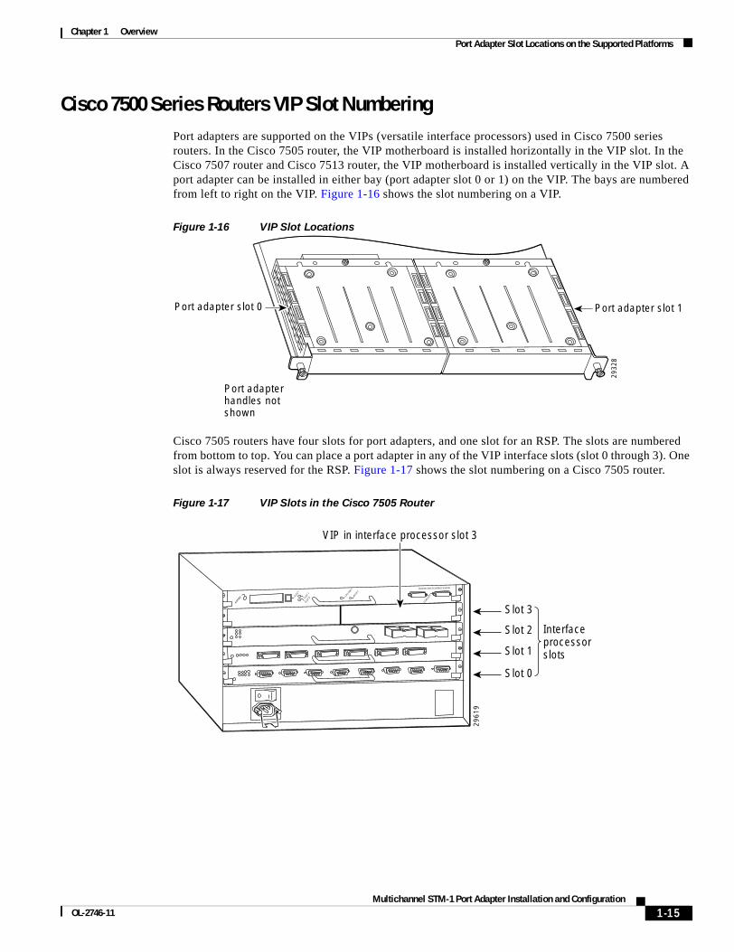
Cisco 7500 Series Routers VIP Slot NumberingPort adapters are supported on the VIPs (versatile interface processors) used in Cisco 7500 series routers. In the Cisco 7505 router, the VIP motherboard is installed horizontally in the VIP slot. In the Cisco 7507 router and Cisco 7513 router, the VIP motherboard is installed vertically in the VIP slot. A port adapter can be installed in either bay (port adapter slot 0 or 1) on the VIP. The bays are numbered from left to right on the VIP. Figure 1-16 shows the slot numbering on a VIP.
Figure 1-16 VIP Slot Locations
Cisco 7505 routers have four slots for port adapters, and one slot for an RSP. The slots are numbered from bottom to top. You can place a port adapter in any of the VIP interface slots (slot 0 through 3). One slot is always reserved for the RSP. Figure 1-17 shows the slot numbering on a Cisco 7505 router.
Figure 1-17 VIP Slots in the Cisco 7505 Router
2932
8
Port adapter slot 0 Port adapter slot 1
Port adapterhandles notshown
29
61
9
Slot 0
Slot 1
Slot 2
Slot 3
Interface processorslots
EJECT
SLOT
0SLOT
1
NORMAL CPU HALT
RESET
CONSOLE
ROUTE SWITCH PROCESSOR
VIP in interface processor slot 3
1-15Multichannel STM-1 Port Adapter Installation and Configuration
OL-2746-11

Chapter 1 Overview Identifying Interface Addresses
Cisco 7507 routers have five slots for port adapters, and two slots for RSPs. The slots are numbered from left to right. You can place a port adapter in any of the VIP interface slots (slot 0, 1, 4, 5, or 6). Slots 2 and 3 are always reserved for RSPs. The Cisco 7507 router is not shown.
Cisco 7513 routers have eleven slots for port adapters, and two slots for RSPs. The slots are numbered from left to right. You can place a port adapter in any of the VIP interface slots (slots 0 through 5, or slots 9 through 12). Slots 6 and 7 are always reserved for RSPs. The Cisco 7513 router is not shown.
Identifying Interface Addresses This section describes how to identify interface addresses for the PA-MC-STM-1 in supported platforms. Interface addresses specify the actual physical location of each interface on a router or switch.
Interfaces on a PA-MC-STM-1 installed in a router maintain the same address regardless of whether other port adapters are installed or removed. However, when you move a port adapter to a different slot, the first number in the interface address changes to reflect the new port adapter slot number.
Interfaces on a PA-MC-STM-1 installed in a FlexWAN module or VIP maintain the same address regardless of whether other modules or interface processors are installed or removed. However, when you move a FlexWAN module or VIP to a different slot, the module or interface processor slot number changes to reflect the new module or interface processor slot.
Note Interface ports are numbered from left to right starting with 0.
The following subsections describe the interface address formats for the supported platforms:
• Catalyst 6000 Family Switches and Cisco 7600 Series Routers with FlexWAN Module Interface Addresses, page 1-18
• Cisco 7200 VXR Routers Interface Addresses, page 1-18
• Cisco 7200 VXR Routers with the Port Adapter Jacket Card Interface Addresses, page 1-19
• Cisco 7201 Routers Interface Addresses, page 1-19
• Cisco 7301 Routers Interface Addresses, page 1-19
• Cisco 7304 Routers with Cisco 7304 PCI Port Adapter Carrier Card Interface Addresses, page 1-19
• Cisco 7401ASR Routers Interface Addresses, page 1-20
• Cisco 7500 Series Routers VIP Interface Addresses, page 1-20
1-16Multichannel STM-1 Port Adapter Installation and Configuration
OL-2746-11

Chapter 1 Overview Identifying Interface Addresses
Table 1-6 summarizes the interface address formats for the supported platforms.
Table 1-6 Identifying Interface Addresses
Platform Interface Address Format Numbers Syntax
Catalyst 6000 family switches and Cisco 7600 series routers (7603, 7606, 7609) with FlexWAN
Module-slot-number/port-adapter-bay-number/interface-port-number
Module slot —21 through 9 (depends on the number of slots in the switch/router)
Port adapter bay—0 or 1
Interface port—0
1. Slot 1 is reserved for the supervisor engine. If a redundant supervisor engine is used, it must go in slot 2; otherwise, slot 2 can be used for other modules.
3/0/0
Cisco 7200 VXR series routers (7204VXR, 7206VXR)
Port-adapter-slot-number/interface-port-number Port adapter slot—12 through 6 (depends on the number of slots in the router)
Interface port—0
2. Port adapter slot 0 is reserved for the Fast Ethernet port on the I/O controller (if present).
1/0
Port Adapter Jacket Card with the Cisco 7200 VXR router3
3. Port adapter slot 0 can accept the Port Adapter Jacket Card if an NPE-G1 or NPE-G2 are installed, but becomes slot 5 on a Cisco 7204VXR router when a port adapter is installed or slot 7 on a Cisco 7206VXR router when a port adapter is installed.
Port-adapter-slot-number/interface-port-number Port adapter slot—1 through 7 (depends on the number of slots in the router)4
Interface port—0
4. Port adapter slot 0 is reserved for the Fast Ethernet port on the I/O controller (if present).
1/0
Cisco 7201 router Port-adapter-slot-number/interface-port number Port adapter slot—always 1
Interface port—0
1/0
Cisco 7301 router Port-adapter-slot-number/interface-port number Port adapter slot—always 1
Interface port—0
1/0
Cisco 7304 PCI port adapter carrier card in Cisco 7304 router
Module-slot-number/interface-port-number Module slot—2 through 5
Interface port—0
3/0
Cisco 7401ASR router
Port-adapter-slot-number/interface-port number Port adapter slot—always 1
Interface port—0
1/0
Cisco 7500 series routers with VIP4-80, VIP6-80
Interface-processor-slot-number/port-adapter-slot-number/interface-port number
Interface processor slot—0 through 12 (depends on the number of slots in the router)
Port adapter slot— 0 or 1
Interface port—0
3/1/0
1-17Multichannel STM-1 Port Adapter Installation and Configuration
OL-2746-11

Chapter 1 Overview Identifying Interface Addresses
Catalyst 6000 Family Switches and Cisco 7600 Series Routers with FlexWAN Module Interface Addresses
In Catalyst 6000 family switches and Cisco 7600 series routers, port adapters are installed in a FlexWAN module, which installs in module slots 2 through 9 (depending on the number of slots in the router). The port adapter can be installed in either bay (port adapter bay 0 or 1) on the FlexWAN module. See Figure 1-8.
The interface address is composed of a three-part number in the format module-slot-number/port-adapter-bay-number/interface-port-number. See Table 1-6.
The first number identifies the module slot of the chassis in which the FlexWAN module is installed (slot 2 through slot 3, 6,or 9 depending on the number of slots in the chassis). These module slots are generally numbered from top to bottom, starting with 1. The Cisco 7609 is the exception with slots numbered right to left, starting with 1.
The second number identifies the bay of the FlexWAN module in which the port adapter is installed (0 or 1). The bays are numbered from left to right on the FlexWAN module.
The third number identifies the physical port number on the port adapter. The PA-MC-STM is a single-port port adapter, therefore the port is always 0.
For example, if a single-port port adapter is installed in the FlexWAN module, which is inserted in module slot 3, port adapter bay 0, then the interface address of the port adapter would be 3/0/0 (module slot 3, port adapter bay 0, and port 0). If the same port adapter is in port adapter bay 1 on the FlexWAN module, the interface addresses would be numbered 3/1/0.
Note The FlexWAN module physical port address begins with slot 0, which differs from the conventional Catalyst 6000 family port address, which begins with slot 1.
Cisco 7200 VXR Routers Interface AddressesIn Cisco 7200 VXR routers, port adapter slots are numbered from the lower left to the upper right, beginning with slot 1 and continuing through slot 4 for the Cisco 7204VXR router, and slot 6 for the Cisco 7206VXR router. Port adapters can be installed in any available port adapter slot from 1 through 6 (depending on the number of slots in the router). Slot 0 is reserved for the I/O controller. See Figure 1-9.
The interface address is composed of a two-part number in the format port-adapter-slot-number/interface-port-number. See Table 1-6. For example, if a single-port PA-MC-STM-1 is installed in slot 1of a Cisco 7200 VXR router, the interface address would be 1/0. If a single-port PA-MC-STM-1 is installed in slot 4, the interface address would be 4/0.
1-18Multichannel STM-1 Port Adapter Installation and Configuration
OL-2746-11

Chapter 1 Overview Identifying Interface Addresses
Cisco 7200 VXR Routers with the Port Adapter Jacket Card Interface AddressesWith an NPE-G1 or NPE-G2 installed, port adapter slot 0 of Cisco 7204VXR router or Cisco 7206VXR router can accept the Port Adapter Jacket Card. When the Port Adapter Jacket Card resides in port adapter slot 0, the port adapter in the Port Adapter Jacket Card is in port adapter slot 5 on the Cisco 7204 VXR router, or port adapter slot 7 on the Cisco 7206 VXR router. See Figure 1-10
The interface address is composed of a two-part number in the format port-adapter-slot-number/interface-port-number. See Table 1-6. For example, if a single-port PA-MC-STM-1 is installed in a Port Adapter Jacket Card in the slot formerly known as slot 0 on a Cisco 7204VXR router, but now known as slot 5, the interface address would be 5/0 (slot 5 and interface port 0). If a single-port PA-MC-STM-1 is installed in a Port Adapter Jacket Card in the slot formerly known as slot 0 on a Cisco 7206VXR router, but now known as slot 7, the interface address would be 7/0 (slot 7 and interface port 0).
Cisco 7201 Routers Interface AddressesIn the Cisco 7201 router, only one slot accepts port adapters and it is numbered as slot 1. See Figure 1-11.
The interface address is composed of a two-part number in the format port-adapter-slot-number/interface-port-number. See Table 1-6. For example, if a single-port PA-MC-STM-1 is installed in a Cisco 7201 router, the interface address would be 1/0.
Cisco 7301 Routers Interface AddressesIn the Cisco 7201 router, only one slot accepts port adapters and it is numbered as slot 1. See Figure 1-12.
The interface address is composed of a two-part number in the format port-adapter-slot-number/interface-port-number. See Table 1-6. For example, if a single-port PA-MC-STM-1 is installed in a Cisco 7201 router, the interface address would be 1/0.
Cisco 7304 Routers with Cisco 7304 PCI Port Adapter Carrier Card Interface Addresses
In the Cisco 7304 router, port adapters are installed in a Cisco 7304 PCI port adapter carrier card, which installs in Cisco 7304 router module slots 2 through 5. The port adapter slot number is the same as the module slot number. See Figure 1-13 and Figure 1-14.
The interface address is composed of a two-part number in the format module-slot-number/interface-port-number. See Table 1-6. For example, if a single-port PA-MC-STM-1 is installed in the Cisco 7304 PCI port adapter carrier card in Cisco 7304 router module slot 3, the interface address would be 3/0.
1-19Multichannel STM-1 Port Adapter Installation and Configuration
OL-2746-11
Chapter 1 Overview Identifying Interface Addresses
Cisco 7401ASR Routers Interface AddressesIn the Cisco 7401ASR router, only one slot accepts port adapters and it is numbered as slot 1. See Figure 1-15
The interface address is composed of a two-part number in the format port-adapter-slot-number/interface-port-number. See Table 1-6. For example, if a single-port PA-MC-STM-1 is installed on a Cisco 7401ASR router, the interface address would be 1/0.
Cisco 7500 Series Routers VIP Interface AddressesIn Cisco 7500 series routers, port adapters are installed on a versatile interface processor (VIP), which installs in interface processor slots 0 through 12 (depending on the number of slots in the router). The port adapter can be installed in either bay (port adapter slot 0 or 1) on the VIP. See Figure 1-16, and Figure 1-17.
The interface address for the VIP is composed of a three-part number in the format interface-processor-slot-number/port-adapter-slot-number/interface-port-number. See Table 1-6.
The first number identifies the slot in which the VIP is installed (slot 0 through 12, depending on the number of slots in the router). These processor slots are numbered from bottom to top starting with 0.
The second number identifies the bay (port adapter slot) on the VIP in which the port adapter is installed (0 or 1). The bays are numbered from left to right on the VIP.
The third number identifies the physical port number (interface port number) on the port adapter. The port numbers always begin at 0 and are numbered from left to right. The number of additional ports depends on the number of ports on the port adapter. The PA-MC-STM-1 is a single-port port adapter, therefore the port is always 0.
For example, if a single-port PA-MC-STM-1 is installed in a VIP in interface processor slot 3, port adapter slot 1, the interface addresses would be 3/1/0. If the PA-MC-STM-1 is in port adapter slot 0 on the VIP, the same interface address would be 3/0/0.
Note Although the processor slots in the seven-slot Cisco 7507 and the thirteen-slot Cisco 7513 chassis are vertically oriented and those in the five-slot Cisco 7505 chassis are horizontally oriented, all Cisco 7500 series routers use the same method for slot and port numbering.
1-20Multichannel STM-1 Port Adapter Installation and Configuration
OL-2746-11

MultichanneOL-2746-11
C H A P T E R2
Preparing for InstallationThis chapter describes the general equipment, safety, and site preparation requirements for installing the PA-MC-STM-1. This chapter contains the following sections:
• Required Tools and Equipment, page 2-1
• Minimum Software and Hardware Requirements, page 2-2
• Checking Hardware and Software Compatibility, page 2-4
• Safety Guidelines, page 2-4
• Laser/LED Safety, page 2-11
• FCC Class A Compliance, page 2-12
Required Tools and EquipmentYou need the following tools and parts to install a PA-MC-STM-1. If you need additional equipment, contact a service representative for ordering information.
• PA-MC-STM-1SMI or PA-MC-STM-1MM
• FlexWAN module (for installation in the Catalyst 6000 family switches or Cisco 7600 series Internet Routers)
• VIP4-80 or VIP6-80 (for installation in Cisco 7500 series chassis only). For information about the specific VIP models that support the PA-MC-STM-1, see the “Minimum Software and Hardware Requirements” section on page 2-2.
• Cisco 7304 PCI Port Adapter Carrier Card (for installation in a Cisco 7304 router)
• Cisco 7200 VXR routers Port Adapter Jacket Card for installation of a port adapter in the I/O controller slot; requires an NPE-G1 or NPE-G2
• One SC-type duplex or two SC-type simplex, multimode or single-mode optical fiber cables to connect the interface with the network. (Single-mode and multimode optical fiber cables for the PA-MC-STM-1 are not available from Cisco Systems but are available from commercial cable vendors. For information about optical fiber cables, see the “Cables, Connectors, and Pinouts” section on page 1-7.)
• Number 1 Phillips and a 3/16-inch flat-blade screwdriver
• Number 2 Phillips screwdriver
• Your own electrostatic discharge (ESD)-prevention equipment or the disposable grounding wrist strap included with all upgrade kits, field-replaceable units (FRUs), and spares
2-1l STM-1 Port Adapter Installation and Configuration

Chapter 2 Preparing for Installation Minimum Software and Hardware Requirements
• Antistatic mat
• Antistatic container
Minimum Software and Hardware RequirementsThis section indicates the recommended minimum Cisco IOS software release required to use the PA-MC-STM-1 in supported platforms.
• Catalyst 6000 Family Switches and Cisco 7600 Series Internet Routers Minimum Hardware and Software Requirements, page 2-2
• Cisco 7200 VXR Routers Minimum Hardware and Software Requirements, page 2-2
• Cisco 7201 Router Minimum Hardware and Software Requirements, page 2-3
• Cisco 7301 Router Minimum Hardware and Software Requirements, page 2-3
• Cisco 7304 Routers with Cisco 7304 PCI Port Adapter Carrier Card Minimum Hardware and Software Requirements, page 2-3
• Cisco 7401ASR Router Minimum Hardware and Software Requirements, page 2-3
• Cisco 7500 Series Routers Minimum Hardware and Software Requirements, page 2-4
For the latest releases supporting the PA-MC-STM-1, refer to the “Checking Hardware and Software Compatibility” section on page 2-4.
Catalyst 6000 Family Switches and Cisco 7600 Series Internet Routers Minimum Hardware and Software Requirements
The PA-MC-STM-1 can be installed in either port adapter slot of a FlexWAN module.
The minimum Cisco IOS software release that supports the PA-MC-STM-1 on a FlexWAN module is Cisco IOS Release 12.1(7)E. For the supervisor engine, the minimum software recommended is the Catalyst 6000 family supervisor engine software release 5.4(1).
For the latest Cisco IOS releases that support the PA-MC-STM-1 on the Catalyst 6000 family switches and Cisco 7600 series Internet Routers, refer to the “Checking Hardware and Software Compatibility” section on page 2-4.
Cisco 7200 VXR Routers Minimum Hardware and Software RequirementsCisco 7200 VXR routers have certain data-carrying capacity (or bandwidth) restrictions that affect the number of high-bandwidth, medium-bandwidth, and low-bandwidth port adapters you can install. For more information on port adapter installation restrictions, refer to the Cisco 7200 Series Port Adapter Hardware Configuration Guidelines at the following URL:
http://www.cisco.com/en/US/products/hw/modules/ps2033/products_configuration_guide_book09186a00801056ef.html
The minimum Cisco IOS software releases that support the PA-MC-STM-1 on the Cisco 7200 VXR routers are Cisco IOS Releases 12.1(7)E and 12.2(4)B.
The minimum Cisco IOS software releases that support the Port Adapter Jacket Card on the Cisco 7200 VXR routers are:
2-2Multichannel STM-1 Port Adapter Installation and Configuration
OL-2746-11

Chapter 2 Preparing for Installation Minimum Software and Hardware Requirements
• Cisco IOS Release 12.4(7) and Cisco IOS Release 12.4(6)T1 with the NPE-G1installed
• Cisco IOS Release 12.4(4)XD2 with the NPE-G2 installed
For the latest Cisco IOS releases that support the PA-MC-STM-1 on the Cisco 7200 VXR routers, refer to the “Checking Hardware and Software Compatibility” section on page 2-4.
Cisco 7201 Router Minimum Hardware and Software RequirementsThe PA-MC-STM-1 can be installed in the single port adapter slot of the Cisco 7201 router.
The minimum Cisco IOS software release that supports the PA-MC-STM-1 on the Cisco 7201 router is Cisco IOS Release 12.4(4)XD7 or Cisco IOS Release 12.2(31)SB5.
For the latest Cisco IOS releases that support the PA-MC-STM-1 on the Cisco 7201 router, refer to the “Checking Hardware and Software Compatibility” section on page 2-4.
Cisco 7301 Router Minimum Hardware and Software RequirementsThe PA-MC-STM-1 can be installed in the single port adapter slot of the Cisco 7301 router.
The minimum Cisco IOS software release that supports the PA-MC-STM-1 on the Cisco 7301 router is Cisco IOS Release 12.2(11)YZ.
For the latest Cisco IOS releases that support the PA-MC-STM-1 on the Cisco 7301 router, refer to the “Checking Hardware and Software Compatibility” section on page 2-4.
Cisco 7304 Routers with Cisco 7304 PCI Port Adapter Carrier Card Minimum Hardware and Software Requirements
The PA-MC-STM-1 can be installed in the Cisco 7304 PCI Port Adapter Carrier Card, which installs in a port adapter slot of the Cisco 7304 router. The Cisco 7304 PCI Port Adapter Carrier Card installs in Cisco 7304 router module slots 2 through 5.
The minimum Cisco IOS software release that supports the PA-MC-STM-1 on the Cisco 7304 routers is Cisco IOS Release 12.2(14)SZ.
For the latest Cisco IOS releases that support the PA-MC-STM-1 on the Cisco 7304 routers and to check which Cisco IOS release can support your specific carrier card/port adapter combination, refer to the “Checking Hardware and Software Compatibility” section on page 2-4.
Cisco 7401ASR Router Minimum Hardware and Software RequirementsThe PA-MC-STM-1 can be installed in the single port adapter slot of the Cisco 7401ASR router.
The minimum Cisco IOS software release that supports the PA-MC-STM-1 on the Cisco 7401ASR router is Cisco IOS Release 12.2(14)S.
For the latest Cisco IOS release that supports the PA-MC-STM-1 on the Cisco 7401ASR router, refer to “Checking Hardware and Software Compatibility” section on page 2-4.
2-3Multichannel STM-1 Port Adapter Installation and Configuration
OL-2746-11

Chapter 2 Preparing for Installation Checking Hardware and Software Compatibility
Cisco 7500 Series Routers Minimum Hardware and Software RequirementsThe PA-MC-STM-1 can be installed in either port adapter slot of the VIP4-80or VIP6-80 on Cisco 7500 series routers.
The minimum Cisco IOS software release that supports the PA-MC-STM-1 on the Cisco 7500 series routers is Cisco IOS Release 12.1(7)E.
For the latest Cisco IOS releases that support the PA-MC-STM-1 on the Cisco 7500 series routers and to check which Cisco IOS release can support your specific VIP/port adapter combination, refer to the “Checking Hardware and Software Compatibility” section on page 2-4.
Checking Hardware and Software CompatibilityTo check the minimum software requirements of Cisco IOS software with the hardware installed on your router, Cisco maintains the Software Advisor tool on Cisco.com. This tool does not verify whether modules within a system are compatible, but it does provide the minimum IOS requirements for individual hardware modules or components.
Note Access to this tool is limited to users with Cisco.com login accounts.
To access Software Advisor, click Log In at Cisco.com and go to Support > Tools and Resources. You can also access the tool by pointing your browser directly to http://www.cisco.com/en/US/support/tsd_most_requested_tools.html.
Choose a product family or enter a specific product number to search for the minimum supported software release needed for your hardware.
Safety GuidelinesThis section provides safety guidelines that you should follow when working with any equipment that connects to electrical power or telephone wiring.
Warning DefinitionSafety warnings appear throughout this publication in procedures that, if performed incorrectly, may cause bodily harm. A warning symbol precedes each warning statement.
2-4Multichannel STM-1 Port Adapter Installation and Configuration
OL-2746-11

Chapter 2 Preparing for Installation Safety Guidelines
Warning IMPORTANT SAFETY INSTRUCTIONS
This warning symbol means danger. You are in a situation that could cause bodily injury. Before you work on any equipment, be aware of the hazards involved with electrical circuitry and be familiar with standard practices for preventing accidents. Use the statement number provided at the end of each warning to locate its translation in the translated safety warnings that accompanied this device. Statement 1071
SAVE THESE INSTRUCTIONS
Waarschuwing BELANGRIJKE VEILIGHEIDSINSTRUCTIES
Dit waarschuwingssymbool betekent gevaar. U verkeert in een situatie die lichamelijk letsel kan veroorzaken. Voordat u aan enige apparatuur gaat werken, dient u zich bewust te zijn van de bij elektrische schakelingen betrokken risico's en dient u op de hoogte te zijn van de standaard praktijken om ongelukken te voorkomen. Gebruik het nummer van de verklaring onderaan de waarschuwing als u een vertaling van de waarschuwing die bij het apparaat wordt geleverd, wilt raadplegen.
BEWAAR DEZE INSTRUCTIES
Varoitus TÄRKEITÄ TURVALLISUUSOHJEITA
Tämä varoitusmerkki merkitsee vaaraa. Tilanne voi aiheuttaa ruumiillisia vammoja. Ennen kuin käsittelet laitteistoa, huomioi sähköpiirien käsittelemiseen liittyvät riskit ja tutustu onnettomuuksien yleisiin ehkäisytapoihin. Turvallisuusvaroitusten käännökset löytyvät laitteen mukana toimitettujen käännettyjen turvallisuusvaroitusten joukosta varoitusten lopussa näkyvien lausuntonumeroiden avulla.
SÄILYTÄ NÄMÄ OHJEET
Attention IMPORTANTES INFORMATIONS DE SÉCURITÉ
Ce symbole d'avertissement indique un danger. Vous vous trouvez dans une situation pouvant entraîner des blessures ou des dommages corporels. Avant de travailler sur un équipement, soyez conscient des dangers liés aux circuits électriques et familiarisez-vous avec les procédures couramment utilisées pour éviter les accidents. Pour prendre connaissance des traductions des avertissements figurant dans les consignes de sécurité traduites qui accompagnent cet appareil, référez-vous au numéro de l'instruction situé à la fin de chaque avertissement.
CONSERVEZ CES INFORMATIONS
Warnung WICHTIGE SICHERHEITSHINWEISE
Dieses Warnsymbol bedeutet Gefahr. Sie befinden sich in einer Situation, die zu Verletzungen führen kann. Machen Sie sich vor der Arbeit mit Geräten mit den Gefahren elektrischer Schaltungen und den üblichen Verfahren zur Vorbeugung vor Unfällen vertraut. Suchen Sie mit der am Ende jeder Warnung angegebenen Anweisungsnummer nach der jeweiligen Übersetzung in den übersetzten Sicherheitshinweisen, die zusammen mit diesem Gerät ausgeliefert wurden.
BEWAHREN SIE DIESE HINWEISE GUT AUF.
2-5Multichannel STM-1 Port Adapter Installation and Configuration
OL-2746-11

Chapter 2 Preparing for Installation Safety Guidelines
Avvertenza IMPORTANTI ISTRUZIONI SULLA SICUREZZA
Questo simbolo di avvertenza indica un pericolo. La situazione potrebbe causare infortuni alle persone. Prima di intervenire su qualsiasi apparecchiatura, occorre essere al corrente dei pericoli relativi ai circuiti elettrici e conoscere le procedure standard per la prevenzione di incidenti. Utilizzare il numero di istruzione presente alla fine di ciascuna avvertenza per individuare le traduzioni delle avvertenze riportate in questo documento.
CONSERVARE QUESTE ISTRUZIONI
Advarsel VIKTIGE SIKKERHETSINSTRUKSJONER
Dette advarselssymbolet betyr fare. Du er i en situasjon som kan føre til skade på person. Før du begynner å arbeide med noe av utstyret, må du være oppmerksom på farene forbundet med elektriske kretser, og kjenne til standardprosedyrer for å forhindre ulykker. Bruk nummeret i slutten av hver advarsel for å finne oversettelsen i de oversatte sikkerhetsadvarslene som fulgte med denne enheten.
TA VARE PÅ DISSE INSTRUKSJONENE
Aviso INSTRUÇÕES IMPORTANTES DE SEGURANÇA
Este símbolo de aviso significa perigo. Você está em uma situação que poderá ser causadora de lesões corporais. Antes de iniciar a utilização de qualquer equipamento, tenha conhecimento dos perigos envolvidos no manuseio de circuitos elétricos e familiarize-se com as práticas habituais de prevenção de acidentes. Utilize o número da instrução fornecido ao final de cada aviso para localizar sua tradução nos avisos de segurança traduzidos que acompanham este dispositivo.
GUARDE ESTAS INSTRUÇÕES
¡Advertencia! INSTRUCCIONES IMPORTANTES DE SEGURIDAD
Este símbolo de aviso indica peligro. Existe riesgo para su integridad física. Antes de manipular cualquier equipo, considere los riesgos de la corriente eléctrica y familiarícese con los procedimientos estándar de prevención de accidentes. Al final de cada advertencia encontrará el número que le ayudará a encontrar el texto traducido en el apartado de traducciones que acompaña a este dispositivo.
GUARDE ESTAS INSTRUCCIONES
Varning! VIKTIGA SÄKERHETSANVISNINGAR
Denna varningssignal signalerar fara. Du befinner dig i en situation som kan leda till personskada. Innan du utför arbete på någon utrustning måste du vara medveten om farorna med elkretsar och känna till vanliga förfaranden för att förebygga olyckor. Använd det nummer som finns i slutet av varje varning för att hitta dess översättning i de översatta säkerhetsvarningar som medföljer denna anordning.
SPARA DESSA ANVISNINGAR
2-6Multichannel STM-1 Port Adapter Installation and Configuration
OL-2746-11

Chapter 2 Preparing for Installation Safety Guidelines
2-7Multichannel STM-1 Port Adapter Installation and Configuration
OL-2746-11

Chapter 2 Preparing for Installation Safety Guidelines
Aviso INSTRUÇÕES IMPORTANTES DE SEGURANÇA
Este símbolo de aviso significa perigo. Você se encontra em uma situação em que há risco de lesões corporais. Antes de trabalhar com qualquer equipamento, esteja ciente dos riscos que envolvem os circuitos elétricos e familiarize-se com as práticas padrão de prevenção de acidentes. Use o número da declaração fornecido ao final de cada aviso para localizar sua tradução nos avisos de segurança traduzidos que acompanham o dispositivo.
GUARDE ESTAS INSTRUÇÕES
Advarsel VIGTIGE SIKKERHEDSANVISNINGER
Dette advarselssymbol betyder fare. Du befinder dig i en situation med risiko for legemesbeskadigelse. Før du begynder arbejde på udstyr, skal du være opmærksom på de involverede risici, der er ved elektriske kredsløb, og du skal sætte dig ind i standardprocedurer til undgåelse af ulykker. Brug erklæringsnummeret efter hver advarsel for at finde oversættelsen i de oversatte advarsler, der fulgte med denne enhed.
GEM DISSE ANVISNINGER
2-8Multichannel STM-1 Port Adapter Installation and Configuration
OL-2746-11

Chapter 2 Preparing for Installation Safety Guidelines
2-9Multichannel STM-1 Port Adapter Installation and Configuration
OL-2746-11

Chapter 2 Preparing for Installation Safety Guidelines
Electrical Equipment GuidelinesFollow these basic guidelines when working with any electrical equipment:
• Before beginning any procedures requiring access to the chassis interior, locate the emergency power-off switch for the room in which you are working.
• Disconnect all power and external cables before moving a chassis.
• Do not work alone when potentially hazardous conditions exist.
• Never assume that power has been disconnected from a circuit; always check.
• Do not perform any action that creates a potential hazard to people or makes the equipment unsafe; carefully examine your work area for possible hazards such as moist floors, ungrounded power extension cables, and missing safety grounds.
Preventing Electrostatic Discharge DamageElectrostatic discharge (ESD) damage, which can occur when electronic cards or components are improperly handled, results in complete or intermittent failures. Port adapters and processor modules comprise printed circuit boards that are fixed in metal carriers. Electromagnetic interference (EMI) shielding and connectors are integral components of the carrier. Although the metal carrier helps to protect the board from ESD, use a preventive antistatic strap during handling.
Following are guidelines for preventing ESD damage:
• Always use an ESD wrist or ankle strap and ensure that it makes good skin contact.
• Connect the equipment end of the strap to an unfinished chassis surface.
• When installing a component, use any available ejector levers or captive installation screws to properly seat the bus connectors in the backplane or midplane. These devices prevent accidental removal, provide proper grounding for the system, and help to ensure that bus connectors are properly seated.
• When removing a component, use any available ejector levers or captive installation screws to release the bus connectors from the backplane or midplane.
• Handle carriers by available handles or edges only; avoid touching the printed circuit boards or connectors.
• Place a removed board component-side-up on an antistatic surface or in a static shielding container. If you plan to return the component to the factory, immediately place it in a static shielding container.
• Avoid contact between the printed circuit boards and clothing. The wrist strap only protects components from ESD voltages on the body; ESD voltages on clothing can still cause damage.
• Never attempt to remove the printed circuit board from the metal carrier.
Caution For safety, periodically check the resistance value of the antistatic strap. The measurement should be between 1 and 10 megohms (Mohms).
2-10Multichannel STM-1 Port Adapter Installation and Configuration
OL-2746-11

Chapter 2 Preparing for Installation Laser/LED Safety
Laser/LED SafetyThe single-mode transmitter in the module uses a small laser to transmit the light signal to the network ring. Keep the transmit port covered whenever a cable is not connected to it. Although multimode transceivers typically use LEDs for transmission, it is good practice to keep open ports covered and avoid staring into open ports or apertures. The single-mode aperture port contains a laser warning label, as shown in Figure 2-1.
Figure 2-1 Laser Warning Labels for Single-Mode Port
Warning Class 1 laser product. Statement 1008.
Warning Invisible laser radiation may be emitted from disconnected fibers or connectors. Do not stare into beams or view directly with optical instruments. Statement 1051.
The multimode aperture contains a Class 1 LED warning label, as shown in Figure 2-2.
Figure 2-2 Class 1 LED Warning Label for Multimode Port
Warning Class 1 LED product. Statement 1027.
Warning Invisible laser radiation may be emitted from the end of the unterminated fiber cable or connector. Do not view directly with optical instruments. Viewing the laser output with certain optical instruments (for example, eye loupes, magnifiers, and microscopes) within a distance of 100 mm may pose an eye hazard. Statement 1056
PRODUIT LASER DE CLASSE 1
CLASS 1 LASER PRODUCT LASERPRODUKT DER KLASSE 1
PRODUCTO LASER CLASE 11
H66
5511
773
CLASS 1 LED PRODUCTPRODUKT MIT KLASSE 1 LED
PRODUIT AVEC VOYANT DEL DE CLASSE 1
PRODUCTO LED DE LA CLASE 1LED
2-11Multichannel STM-1 Port Adapter Installation and Configuration
OL-2746-11

Chapter 2 Preparing for Installation FCC Class A Compliance
FCC Class A ComplianceThis equipment has been tested and found to comply with the limits for a Class A digital device, pursuant to part 15 of the FCC rules. These limits are designed to provide reasonable protection against harmful interference when the equipment is operated in a commercial environment. This equipment generates, uses, and can radiate radio-frequency energy and, if not installed and used in accordance with the instruction manual, may cause harmful interference to radio communications. Operation of this equipment in a residential area is likely to cause harmful interference, in which case users will be required to correct the interference at their own expense.
You can determine whether your equipment is causing interference by turning it off. If the interference stops, it was probably caused by the Cisco equipment or one of its peripheral devices. If the equipment causes interference to radio or television reception, try to correct the interference by using one or more of the following measures:
• Turn the television or radio antenna until the interference stops.
• Move the equipment to one side or the other of the television or radio.
• Move the equipment farther away from the television or radio.
• Plug the equipment into an outlet that is on a different circuit from the television or radio. (That is, make certain the equipment and the television or radio are on circuits controlled by different circuit breakers or fuses.)
Caution This product has been designed to meet these requirements. Modifications to this product that are not authorized by Cisco Systems, Inc. could void the various approvals and negate your authority to operate the product.
2-12Multichannel STM-1 Port Adapter Installation and Configuration
OL-2746-11
MultichanneOL-2746-11
C H A P T E R3
Removing and Installing Port AdaptersThis chapter describes how to remove the PA-MC-STM-1 port adapter from supported platforms and also how to install a new or replacement port adapter. This chapter contains the following sections:
• Handling Port Adapters, page 3-1
• Online Insertion and Removal, page 3-2
• Warnings and Cautions, page 3-3
• Port Adapter Removal and Installation, page 3-12
• Connecting a PA-MC-STM-1 Cable, page 3-23
Handling Port AdaptersEach port adapter circuit board is mounted to a metal carrier and is sensitive to electrostatic discharge (ESD) damage.
Note When a slot is not in use, a blank port adapter must fill the empty slot to allow the router or switch to conform to electromagnetic interference (EMI) emissions requirements and to allow proper airflow across the port adapters. If you plan to install a new port adapter in a slot that is not in use, you must first remove the blank port adapter.
Caution When powering off the router, wait a minimum of 30 seconds before powering it on again.
Caution Always handle the port adapter by the carrier edges and handle; never touch the port adapter components or connector pins. (See Figure 3-1.)
3-1l STM-1 Port Adapter Installation and Configuration
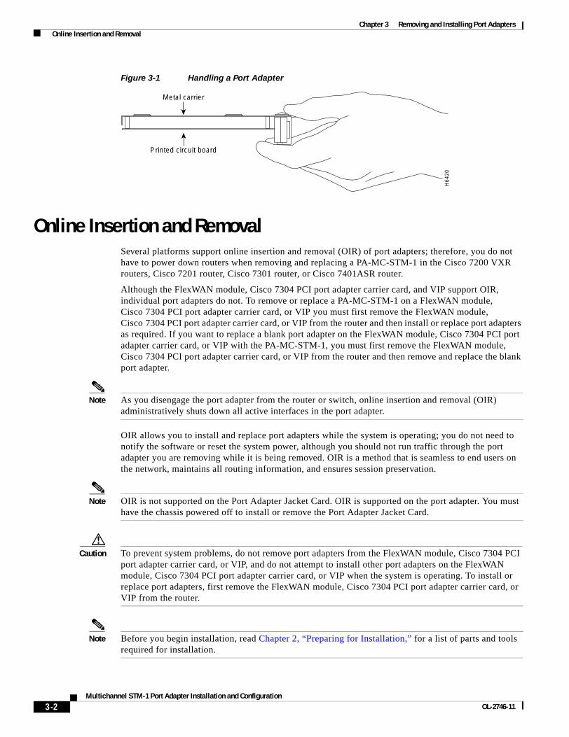
Chapter 3 Removing and Installing Port Adapters Online Insertion and Removal
Figure 3-1 Handling a Port Adapter
Online Insertion and RemovalSeveral platforms support online insertion and removal (OIR) of port adapters; therefore, you do not have to power down routers when removing and replacing a PA-MC-STM-1 in the Cisco 7200 VXR routers, Cisco 7201 router, Cisco 7301 router, or Cisco 7401ASR router.
Although the FlexWAN module, Cisco 7304 PCI port adapter carrier card, and VIP support OIR, individual port adapters do not. To remove or replace a PA-MC-STM-1 on a FlexWAN module, Cisco 7304 PCI port adapter carrier card, or VIP you must first remove the FlexWAN module, Cisco 7304 PCI port adapter carrier card, or VIP from the router and then install or replace port adapters as required. If you want to replace a blank port adapter on the FlexWAN module, Cisco 7304 PCI port adapter carrier card, or VIP with the PA-MC-STM-1, you must first remove the FlexWAN module, Cisco 7304 PCI port adapter carrier card, or VIP from the router and then remove and replace the blank port adapter.
Note As you disengage the port adapter from the router or switch, online insertion and removal (OIR) administratively shuts down all active interfaces in the port adapter.
OIR allows you to install and replace port adapters while the system is operating; you do not need to notify the software or reset the system power, although you should not run traffic through the port adapter you are removing while it is being removed. OIR is a method that is seamless to end users on the network, maintains all routing information, and ensures session preservation.
Note OIR is not supported on the Port Adapter Jacket Card. OIR is supported on the port adapter. You must have the chassis powered off to install or remove the Port Adapter Jacket Card.
Caution To prevent system problems, do not remove port adapters from the FlexWAN module, Cisco 7304 PCI port adapter carrier card, or VIP, and do not attempt to install other port adapters on the FlexWAN module, Cisco 7304 PCI port adapter carrier card, or VIP when the system is operating. To install or replace port adapters, first remove the FlexWAN module, Cisco 7304 PCI port adapter carrier card, or VIP from the router.
Note Before you begin installation, read Chapter 2, “Preparing for Installation,” for a list of parts and tools required for installation.
H64
20
Metal carrier
Printed circuit board
3-2Multichannel STM-1 Port Adapter Installation and Configuration
OL-2746-11

Chapter 3 Removing and Installing Port Adapters Warnings and Cautions
Warnings and CautionsObserve the following warnings and cautions when installing or removing modules:
• Do not slide a port adapter all the way into the slot until you have connected all required cables. Trying to do so disrupts normal operation of the router or switch.
• If a port adapter lever or other retaining mechanism does not move to the locked position, the port adapter is not completely seated in the midplane. Carefully pull the port adapter halfway out of the slot, reinsert it, and move the port adapter lever or other mechanism to the locked position.
• To prevent jamming the carrier between the upper and the lower edges of the port adapter slot, and to ensure that the edge connector at the rear of the port adapter mates with the connection at the rear of the port adapter slot, make certain that the carrier is positioned correctly, as shown in the cutaway illustrations in the “Port Adapter Removal and Installation” section on page 3-12.
Equipment Installation Warning
Warning Only trained and qualified personnel should be allowed to install, replace, or service this equipment. Statement 1030
Waarschuwing Deze apparatuur mag alleen worden geïnstalleerd, vervangen of hersteld door bevoegd geschoold personeel.
Varoitus Tämän laitteen saa asentaa, vaihtaa tai huoltaa ainoastaan koulutettu ja laitteen tunteva henkilökunta.
Attention Il est vivement recommandé de confier l'installation, le remplacement et la maintenance de ces équipements à des personnels qualifiés et expérimentés.
Warnung Das Installieren, Ersetzen oder Bedienen dieser Ausrüstung sollte nur geschultem, qualifiziertem Personal gestattet werden.
Avvertenza Questo apparato può essere installato, sostituito o mantenuto unicamente da un personale competente.
Advarsel Bare opplært og kvalifisert personell skal foreta installasjoner, utskiftninger eller service på dette utstyret.
Aviso Apenas pessoal treinado e qualificado deve ser autorizado a instalar, substituir ou fazer a revisão deste equipamento.
¡Advertencia! Solamente el personal calificado debe instalar, reemplazar o utilizar este equipo.
Varning! Endast utbildad och kvalificerad personal bör få tillåtelse att installera, byta ut eller reparera denna utrustning.
3-3Multichannel STM-1 Port Adapter Installation and Configuration
OL-2746-11

Chapter 3 Removing and Installing Port Adapters Warnings and Cautions
Aviso Somente uma equipe treinada e qualificada tem permissão para instalar, substituir ou dar manutenção a este equipamento.
Advarsel Kun uddannede personer må installere, udskifte komponenter i eller servicere dette udstyr.
3-4Multichannel STM-1 Port Adapter Installation and Configuration
OL-2746-11

Chapter 3 Removing and Installing Port Adapters Warnings and Cautions
Safety Cover Requirement Warning
Warning The safety cover is an integral part of the product. Do not operate the unit without the safety cover installed. Operating the unit without the cover in place will invalidate the safety approvals and pose a risk of fire and electrical hazards. Statement 117
Waarschuwing Het beveiligingsdeksel is een integraal onderdeel van het product. Deze eenheid niet bedienen als het beveiligingsdeksel niet geïnstalleerd is. Als het deksel niet op zijn plaats is tijdens de bediening, zal dit de veiligheidsaanbevelingen ongeldig maken en een risico op brand en elektrische gevaren vormen.
Varoitus Suojakansi on tärkeä osa tuotetta. Yksikköä ei saa käyttää ilman suojakantta. Yksikön käyttö ilman suojakantta mitätöi turvallisuushyväksynnät ja aiheuttaa tulipalon ja sähköiskun vaaran.
Attention Le plateau de sécurité est une partie intégrante du produit. Pour éviter tout risque de feu ou d'accident électrique, n'utilisez jamais l'unité lorsque ce plateau n'est pas installé. Les garanties de sécurité seraient annulées.
Warnung Die Sicherheitsabdeckung ist integraler Bestandteil des Produkts. Die Einheit darf nicht ohne installierte Sicherheitsabdeckung betrieben werden. Ein Betreiben der Einheit ohne korrekt installierte Abdeckung verstößt gegen die Sicherheitsnormen und führt zu Brandgefahr sowie elektrischen Sicherheitsrisiken.
Avvertenza Attenzione: Il pannello di sicurezza è parte integrante del prodotto. Non fate funzionare il sistema senza il pannello di sicurezza. Far funzionare il sistema senza il pannello invaliderà le certificazioni di sicurezza e può'dare luogo a rischi di incendio e a cortocircuiti.
Advarsel Dette sikkerhetsdekselet er en integral del av produktet. Enheten skal ikke brukes uten at sikkerhetsdekselet er montert. Bruk av enheten uten at sikkerhetsdekselet sitter på plass, vil ugyldiggjøre sikkerhetsgodkjenningene, og kan dessuten utgjøre fare for brann og faremomenter i forbindelse med elektrisitet.
Aviso A cobertura de segurança é uma parte integral do produto. Não opere a unidade sem a respectiva cobertura de segurança instalada. Operar a unidade sem esta cobertura anulará as aprovações de segurança e constituirá um risco de incêndio e perigo eléctrico.
¡Advertencia! La cubierta de seguridad forma parte integral del producto. No haga funcionar este producto sin la cubierta de seguridad instalada, de lo contrario se invalidarían las aprobaciones de seguridad y se correría el riesgo de incendio o de descargas eléctricas.
Varning! Skyddshuven är en väsentlig del av produkten. Använd inte enheten utan installerad skyddshuv. Om enheten används utan skyddshuven på plats upphävs alla säkerhetsgodkännanden och risk för brandfara och elektrisk fara föreligger.
3-5Multichannel STM-1 Port Adapter Installation and Configuration
OL-2746-11

Chapter 3 Removing and Installing Port Adapters Warnings and Cautions
Blank Faceplates and Cover Panels Warning
Warning Blank faceplates and cover panels serve three important functions: they prevent exposure to hazardous voltages and currents inside the chassis; they contain electromagnetic interference (EMI) that might disrupt other equipment; and they direct the flow of cooling air through the chassis. Do not operate the system unless all cards, faceplates, front covers, and rear covers are in place. Statement 1029
Waarschuwing Lege vlakplaten en afdekpanelen vervullen drie belangrijke functies: ze voorkomen blootstelling aan gevaarlijke voltages en stroom binnenin het frame, ze bevatten elektromagnetische storing (EMI) hetgeen andere apparaten kan verstoren en ze leiden de stroom van koellucht door het frame. Het systeem niet bedienen tenzij alle kaarten, vlakplaten en afdekkingen aan de voor- en achterkant zich op hun plaats bevinden.
Varoitus Tyhjillä tasolaikoilla ja suojapaneeleilla on kolme tärkeää käyttötarkoitusta: Ne suojaavat asennuspohjan sisäisille vaarallisille jännitteille ja sähkövirralle altistumiselta; ne pitävät sisällään elektromagneettisen häiriön (EMI), joka voi häiritä muita laitteita; ja ne suuntaavat tuuletusilman asennuspohjan läpi. Järjestelmää ei saa käyttää, elleivät kaikki tasolaikat, etukannet ja takakannet ole kunnolla paikoillaan.
Attention Ne jamais faire fonctionner le système sans que l’intégralité des cartes, des plaques métalliques et des panneaux avant et arrière ne soient fixés à leur emplacement. Ceux-ci remplissent trois fonctions essentielles : ils évitent tout risque de contact avec des tensions et des courants dangereux à l’intérieur du châssis, ils évitent toute diffusion d’interférences électromagnétiques qui pourraient perturber le fonctionnement des autres équipements, et ils canalisent le flux d’air de refroidissement dans le châssis.
Warnung Blanke Faceplates und Abdeckungen haben drei wichtigen Funktionen: (1) Sie schützen vor gefährlichen Spannungen und Strom innerhalb des Chassis; (2) sie halten elektromagnetische Interferenzen (EMI) zurück, die andere Geräte stören könnten; (3) sie lenken den kühlenden Luftstrom durch das Chassis. Das System darf nur betrieben werden, wenn alle Karten, Faceplates, Voder- und Rückabdeckungen an Ort und Stelle sind.
Avvertenza Le piattaforme bianche e i panelli di protezione hanno tre funzioni importanti: Evitano l'esposizione a voltaggi e correnti elettriche pericolose nello chassis, trattengono le interferenze elettromagnetiche (EMI) che potrebbero scombussolare altri apparati e dirigono il flusso di aria per il raffreddamento attraverso lo chassis. Non mettete in funzione il sistema se le schede, le piattaforme, i panelli frontali e posteriori non sono in posizione.
Advarsel Blanke ytterplater og deksler sørger for tre viktige funksjoner: de forhindrer utsettelse for farlig spenning og strøm inni kabinettet; de inneholder elektromagnetisk forstyrrelse (EMI) som kan avbryte annet utstyr, og de dirigerer luftavkjølingsstrømmen gjennom kabinettet. Betjen ikke systemet med mindre alle kort, ytterplater, frontdeksler og bakdeksler sitter på plass.
Aviso As faces furadas e os painéis de protecção desempenham três importantes funções: previnem contra uma exposição perigosa a voltagens e correntes existentes no interior do chassis; previnem contra interferência electromagnética (EMI) que poderá danificar outro equipamento; e canalizam o fluxo do ar de refrigeração através do chassis. Não deverá operar o sistema sem que todas as placas, faces, protecções anteriores e posteriores estejam nos seus lugares.
3-6Multichannel STM-1 Port Adapter Installation and Configuration
OL-2746-11

Chapter 3 Removing and Installing Port Adapters Warnings and Cautions
¡Advertencia! Las placas frontales y los paneles de relleno cumplen tres funciones importantes: evitan la exposición a niveles peligrosos de voltaje y corriente dentro del chasis; reducen la interferencia electromagnética (EMI) que podría perturbar la operación de otros equipos y dirigen el flujo de aire de enfriamiento a través del chasis. No haga funcionar el sistema a menos que todas las tarjetas, placas frontales, cubiertas frontales y cubiertas traseras estén en su lugar.
Varning! Tomma framplattor och skyddspaneler har tre viktiga funktioner: de förhindrar att personer utsätts för farlig spänning och ström som finns inuti chassit; de innehåller elektromagnetisk interferens (EMI) som kan störa annan utrustning; och de styr riktningen på kylluftsflödet genom chassit. Använd inte systemet om inte alla kort, framplattor, fram- och bakskydd är på plats.
Aviso Plaquetas vazias e painéis de proteção têm três funções importantes: impedem a exposição a tensões e correntes elétricas perigosas dentro do chassi; apresentam interferência eletromagnética (EMI) que pode danificar outros equipamentos: direcionam o fluxo do ar refrigerado pelo chassi. Não opere o sistema a menos que todas as placas, plaquetas, tampas frontais e tampas traseiras estejam em seu devido lugar.
Advarsel Blanke frontplader og sidepaneler tjener tre vigtige formål: de forhinder udsættelse for farlig spænding og strøm inde i chassiset, de isolerer elektromagnetisk interferens (EMI), der kan forstyre andet udstyr, og de leder en strøm af kølig luft gennem chassiset. Betjen ikke systemet medmindre alle kort, frontplader, sidepaneler og bagpaneler er på plads.
3-7Multichannel STM-1 Port Adapter Installation and Configuration
OL-2746-11

Chapter 3 Removing and Installing Port Adapters Warnings and Cautions
3-8Multichannel STM-1 Port Adapter Installation and Configuration
OL-2746-11

Chapter 3 Removing and Installing Port Adapters Warnings and Cautions
Jewelry Removal Warning
Warning Before working on equipment that is connected to power lines, remove jewelry (including rings, necklaces, and watches). Metal objects will heat up when connected to power and ground and can cause serious burns or weld the metal object to the terminals. Statement 43
Waarschuwing Alvorens aan apparatuur te werken die met elektrische leidingen is verbonden, sieraden (inclusief ringen, kettingen en horloges) verwijderen. Metalen voorwerpen worden warm wanneer ze met stroom en aarde zijn verbonden, en kunnen ernstige brandwonden veroorzaken of het metalen voorwerp aan de aansluitklemmen lassen.
Varoitus Ennen kuin työskentelet voimavirtajohtoihin kytkettyjen laitteiden parissa, ota pois kaikki korut (sormukset, kaulakorut ja kellot mukaan lukien). Metalliesineet kuumenevat, kun ne ovat yhteydessä sähkövirran ja maan kanssa, ja ne voivat aiheuttaa vakavia palovammoja tai hitsata metalliesineet kiinni liitäntänapoihin.
Attention Avant d’accéder à cet équipement connecté aux lignes électriques, ôter tout bijou (anneaux, colliers et montres compris). Lorsqu’ils sont branchés à l’alimentation et reliés à la terre, les objets métalliques chauffent, ce qui peut provoquer des blessures graves ou souder l’objet métallique aux bornes.
Warnung Vor der Arbeit an Geräten, die an das Netz angeschlossen sind, jeglichen Schmuck (einschließlich Ringe, Ketten und Uhren) abnehmen. Metallgegenstände erhitzen sich, wenn sie an das Netz und die Erde angeschlossen werden, und können schwere Verbrennungen verursachen oder an die Anschlußklemmen angeschweißt werden.
Avvertenza Prima di intervenire su apparecchiature collegate alle linee di alimentazione, togliersi qualsiasi monile (inclusi anelli, collane, braccialetti ed orologi). Gli oggetti metallici si riscaldano quando sono collegati tra punti di alimentazione e massa: possono causare ustioni gravi oppure il metallo può saldarsi ai terminali.
Advarsel Fjern alle smykker (inkludert ringer, halskjeder og klokker) før du skal arbeide på utstyr som er koblet til kraftledninger. Metallgjenstander som er koblet til kraftledninger og jord blir svært varme og kan forårsake alvorlige brannskader eller smelte fast til polene.
Aviso Antes de trabalhar em equipamento que esteja ligado a linhas de corrente, retire todas as jóias que estiver a usar (incluindo anéis, fios e relógios). Os objectos metálicos aquecerão em contacto com a corrente e em contacto com a ligação à terra, podendo causar queimaduras graves ou ficarem soldados aos terminais.
¡Advertencia! Antes de operar sobre equipos conectados a líneas de alimentación, quitarse las joyas (incluidos anillos, collares y relojes). Los objetos de metal se calientan cuando se conectan a la alimentación y a tierra, lo que puede ocasionar quemaduras graves o que los objetos metálicos queden soldados a los bornes.
Varning! Tag av alla smycken (inklusive ringar, halsband och armbandsur) innan du arbetar på utrustning som är kopplad till kraftledningar. Metallobjekt hettas upp när de kopplas ihop med ström och jord och kan förorsaka allvarliga brännskador; metallobjekt kan också sammansvetsas med kontakterna.
3-9Multichannel STM-1 Port Adapter Installation and Configuration
OL-2746-11

Chapter 3 Removing and Installing Port Adapters Warnings and Cautions
Wrist Strap and Midplane Contact Warning
Warning During this procedure, wear grounding wrist straps to avoid ESD damage to the card. Do not directly touch the midplane with your hand or any metal tool, or you could shock yourself. Statement 181
Waarschuwing Draag tijdens deze procedure aardingspolsbanden om te vermijden dat de kaart beschadigd wordt door elektrostatische ontlading. Raak het middenbord niet rechtstreeks aan met uw hand of met een metalen werktuig, omdat u anders een elektrische schok zou kunnen oplopen.
Varoitus Käytä tämän toimenpiteen aikana maadoitettuja rannesuojia estääksesi sähköstaattisen purkauksen aiheuttaman kortin vaurioitumisen. Älä kosketa piirikorttia suoraan kädelläsi tai metallisella työkalulla sähköiskuvaaran vuoksi.
Attention Lors de cette procédure, il vivement recommandé de porter des bracelets antistatiques pour éviter que des décharges électriques n’endommagent la carte. En outre, pour éviter tout risque de choc électrique, ne touchez jamais le fond de panier central directement avec la main ou avec un outil métallique.
Warnung Vermeidung einer Beschädigung der Karte durch elektrostatische Entladung während dieses Verfahrens ein Erdungsband am Handgelenk tragen. Bei Berührung der Midplane-Karte mit der Hand oder einem metallenen Werkzeug besteht Elektroschockgefahr.
Avvertenza Durante questa procedura, indossare bracciali antistatici per evitare danni alla scheda causati da un’eventuale scarica elettrostatica. Non toccare direttamente il midplane delle connessioni, né con le mani né con un qualsiasi utensile metallico, perché esiste il pericolo di folgorazione.
3-10Multichannel STM-1 Port Adapter Installation and Configuration
OL-2746-11

Chapter 3 Removing and Installing Port Adapters Warnings and Cautions
Advarsel Bruk jordingsarmbånd under prosedyren for å unngå ESD-skader på kortet. Unngå direkte berøring av mellomplanet med hånden eller metallverktøy, slik at du ikke får elektrisk støt.
Aviso Durante este procedimento, e para evitar danos por descarga electrostática causados à placa, usar fitas de ligação à terra para os pulsos. Para evitar o risco de choque eléctrico, não tocar directamente na parte central com a mão ou com qualquer ferramenta metálica.
¡Advertencia! Durante este procedimiento usar tiras conectadas a tierra en las muñecas para evitar daños en la tarjeta causados por descargas electrostáticas. No tocar el plano mediano con las manos ni con ninguna herramienta metálica, ya que podría producir un choque eléctrico.
Varning! Använd jordade armbandsremmar under denna procedur för att förhindra elektrostatisk skada på kortet. Rör ej vid kortets mittdel med handen eller metallverktyg då detta kan orsaka elektrisk stöt.
Aviso Durante esse procedimento, use pulseiras antiestáticas aterradas para evitar danos de descarga eletrostática (ESD) à placa. Não toque no painel auxiliar diretamente com a mão ou com qualquer ferramenta metálica ou você correrá o risco de receber um choque elétrico.
Advarsel Under denne procedure skal du bære håndledsbånd med jordforbindelse for at undgå at udsætte kortet for statisk elektricitet. Undgå at berøre midterpladen direkte med hånden eller med et stykke metalværktøj, da der er risiko for stød.
3-11Multichannel STM-1 Port Adapter Installation and Configuration
OL-2746-11
Chapter 3 Removing and Installing Port Adapters Port Adapter Removal and Installation
Port Adapter Removal and InstallationIn this section, the illustrations that follow give step-by-step instructions on how to remove and install port adapters. Although the procedures may refer to a particular type of port adapter, the steps are the same for installing and removing all types of port adapters. This section contains the following illustrations:
• Catalyst 6000 Family Switches and Cisco 7600 Series Internet Routers with FlexWAN Module—Removing and Installing a Port Adapter, page 3-13
• Cisco 7200 VXR Routers—Removing and Installing a Port Adapter, page 3-14
• Cisco 7200 VXR Routers—Removing and Installing a Port Adapter in a Port Adapter Jacket Card, page 3-15
• Cisco 7201 Router—Removing and Installing a Port Adapter, page 3-17
• Cisco 7301 Router—Removing and Installing a Port Adapter, page 3-18
• Cisco 7304 PCI Port Adapter Carrier Card—Removing and Installing a Port Adapter, page 3-19
• Cisco 7401ASR Router—Removing and Installing a Port Adapter, page 3-21
• Cisco 7500 Series Routers with VIP—Removing and Installing a Port Adapter, page 3-22
3-12Multichannel STM-1 Port Adapter Installation and Configuration
OL-2746-11
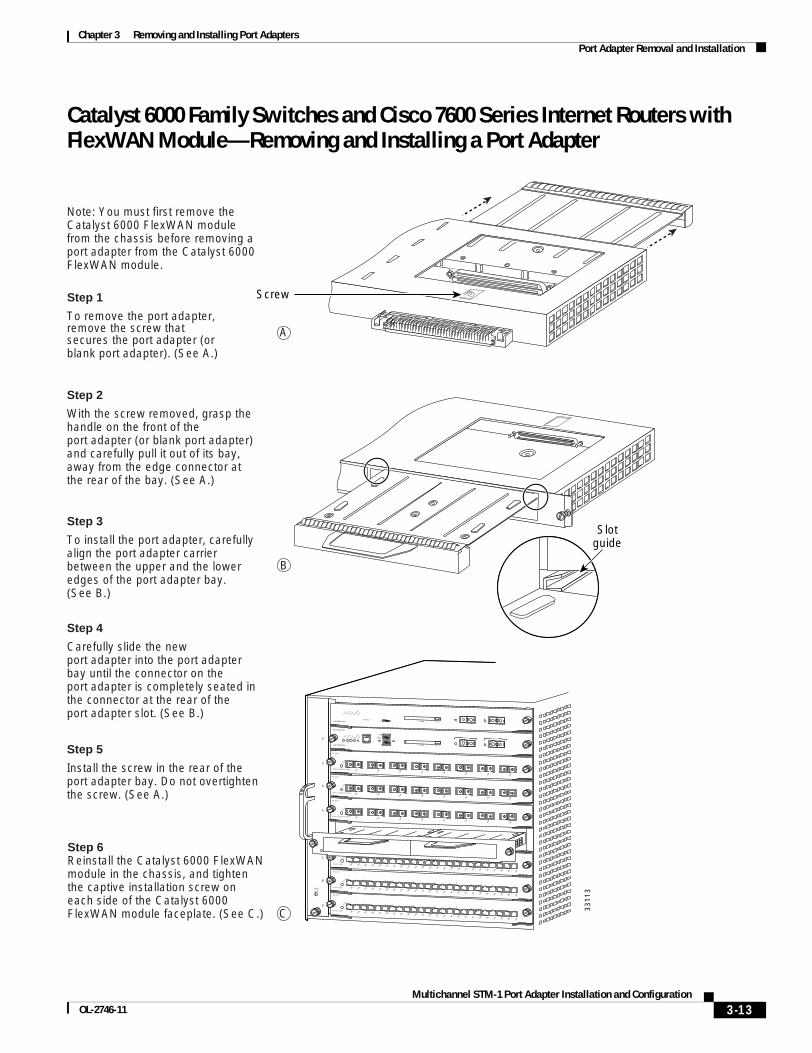
Chapter 3 Removing and Installing Port Adapters Port Adapter Removal and Installation
Catalyst 6000 Family Switches and Cisco 7600 Series Internet Routers with FlexWAN Module—Removing and Installing a Port Adapter
Note: You must first remove the Catalyst 6000 FlexWAN module from the chassis before removing a port adapter from the Catalyst 6000 FlexWAN module.
Step 2
With the screw removed, grasp the handle on the front of theport adapter (or blank port adapter) and carefully pull it out of its bay, away from the edge connector at the rear of the bay. (See A.)
Step 3
To install the port adapter, carefully align the port adapter carrier between the upper and the lower edges of the port adapter bay.(See B.)
Step 5
Install the screw in the rear of the port adapter bay. Do not overtighten the screw. (See A.)
Step 6Reinstall the Catalyst 6000 FlexWAN module in the chassis, and tighten the captive installation screw on each side of the Catalyst 6000 FlexWAN module faceplate. (See C.) 3
3113
B
A
C
Step 1
To remove the port adapter,remove the screw thatsecures the port adapter (orblank port adapter). (See A.)
Step 4
Carefully slide the newport adapter into the port adapter bay until the connector on theport adapter is completely seated in the connector at the rear of theport adapter slot. (See B.)
Slotguide
Screw
FANLED
2
3
4
5
6
7
8
9
SUPERVISOR I
STATUS
SYSTEM
ACTIVE
PWR M
GMT
RESET
CONSOLE1% PCMCIA EJECT LIN
K
LINK
SUPERVISOR I
WS-X6K-SUP1
STATUS
SYSTEM
ACTIVE
PWR M
GMT
RESET
CONSOLE
Switch Load 100%
1%
DTE/ DCE
PCMCIA EJECT
PORT 1
LINK
PORT 2
LINK
8 PORT GIGABIT ETHERNET
WS-X6408
1
LINK
STATUS 2 3 4 5 6 7 8
LINK
LINK
LINK
LINK
LINK
LINK
LINK
8 PORT GIGABIT ETHERNET
WS-X6408
1
LINK
STATUS 2 3 4 5 6 7 8
LINK
LINK
LINK
LINK
LINK
LINK
LINK
8 PORT GIGABIT ETHERNET
WS-X6408
1
LINK
STATUS 2 3 4 5 6 7 8
LINK
LINK
LINK
LINK
LINK
LINK
LINK
24 PORT 100FX
WS-X6224
STATUS
24 PORT 100FX
WS-X6224
STATUS
24 PORT 100FX
WS-X6224
STATUS1
LINK
2
LINK
3
LINK
4
LINK
5
LINK
6
LINK
7
LINK
8
LINK
9
LINK
10
LINK
11
LINK
12
LINK
13
LINK
14
LINK
15
LINK
16
LINK
17
LINK
18
LINK
19
LINK
20
LINK
21
LINK
22
LINK
23
LINK
24
LINK
1
LINK
2
LINK
3
LINK
4
LINK
5
LINK
6
LINK
7
LINK
8
LINK
9
LINK
10
LINK
11
LINK
12
LINK
13
LINK
14
LINK
15
LINK
16
LINK
17
LINK
18
LINK
19
LINK
20
LINK
21
LINK
22
LINK
23
LINK
24
LINK
1
LINK
2
LINK
3
LINK
4
LINK
5
LINK
6
LINK
7
LINK
8
LINK
9
LINK
10
LINK
11
LINK
12
LINK
13
LINK
14
LINK
15
LINK
16
LINK
17
LINK
18
LINK
19
LINK
20
LINK
21
LINK
22
LINK
23
LINK
24
LINK
STATUS
3-13Multichannel STM-1 Port Adapter Installation and Configuration
OL-2746-11

Chapter 3 Removing and Installing Port Adapters Port Adapter Removal and Installation
Cisco 7200 VXR Routers—Removing and Installing a Port Adapter
Step 1
To remove the port adapter, place the port adapter lever in the unlocked position. (See A.) Theport adapter lever remains in the unlocked position.
Step 2
Grasp the handle of the port adapter and pull the port adapter from the router, about halfway out of its slot. If you are removing a blank port adapter, pull the blank port adapter completely out of the chassis slot.
Step 3
With the port adapter halfway out of the slot, disconnect all cables from the port adapter. After disconnecting the cables, pull the port adapter from its chassis slot.
Step 4
To insert the port adapter, carefully align the port adapter carrier between the upper and the lower edges of the port adapter slot.(See B.)
Step 5
Carefully slide the new port adapter halfway into the port adapter slot. (See B.)
Step 6
With the port adapter halfway into the slot, connect all required cables to the port adapter. After connecting all required cables, carefully slide the port adapter all the way into the slot until the port adapter is seated in the router midplane.
Step 7
After the port adapter is properly seated, lock the port adapter lever. (See A.)
2799
6
2
0
4
1
3
56
FAST SERIAL
ENTD TC RD RC LB CD TD TC RD RC LB CD TD TC RD RC LB CD TD TC RD RC LB CD
TOKEN RING
0 1 2 3
Cisco 7200Series
CPU RESET
ENABLED
MII
EN R
J45
EN R
J45
LINK
1O P
WR
OK
RJ-45
FAST ETHERNET INPUT/OUTPUT CONTROLLER
PCMCIA
EJECT
SLOT 0
SLOT 1
FE MII
ENABLE
D
MII
LIN
K
RJ4
5
FAST ETHERNET
0
ETHERNET 10BT
ENABLE
D
0 2
1 3
LINK
0 1 2 3
Port adapter lever(locked position)
Port adapter lever(unlocked position)
Note: This adapter removal applies to any port or service adapter.
A
BM
II
EN R
J45
EN R
J45
LINK
1O P
WR
OK
RJ-45
CPU RESET
FAST ETHERNET INPUT/OUTPUT CONTROLLER
ENABLED
PCMCIA
EJECT
SLOT 0
SLOT 1
FE MII
2
4
6
Cisco 7200Series
1
3
5
ETHERNET 10BT
ENABLE
D
0 2
1 3
LINK
0 1 2 3
ENABLE
D
MII
LIN
K
RJ4
5
FAST ETHERNET
0TOKEN RING
0 1 2 3Slotguide
3-14Multichannel STM-1 Port Adapter Installation and Configuration
OL-2746-11

Chapter 3 Removing and Installing Port Adapters Port Adapter Removal and Installation
Cisco 7200 VXR Routers—Removing and Installing a Port Adapter in a Port Adapter Jacket Card
The Port Adapter Jacket Card is used in the I/O controller slot of a Cisco 7200 VXR router with either an NPE-G1 or NPE-G2 installed, and allows a port adapter to be installed in it. Both the NPE-G1 and NPE-G2 incorporate I/O controller functionality, so that with either network processing engine the I/O controller slot is available. The NPE-G1 and NPE-G2 have a third dedicated peripheral component interconnect (PCI) bus that provides additional bandwidth to the chassis. The third PCI bus allows a port adapter with a high bandwidth point requirement to be used with the Port Adapter Jacket Card in the I/O controller slot.
Note Online insertion and removal (OIR) is not supported on the Port Adapter Jacket Card. OIR is supported on the port adapter. You must have the chassis powered off to install or remove the Port Adapter Jacket Card.
Figure 3-2 Port Adapter Jacket Card Faceplate
Use the following information to install a port adapter into an installed Port Adapter Jacket Card. For information on installing the Port Adapter Jacket Card into a Cisco 7200 VXR router, see the Port Adapter Jacket Card Installation Guide.
1 Captive installation screw 4 Handle
2 ENABLE LED 5 Port adapter slot
3 PWR (power) LED
Table 3-1 Port Adapter Jacket Card LEDs
LED Color Indicates
ENABLE Green Port Adapter Jacket Card is enabled for operation.
Off Port Adapter Jacket Card is not enabled for operation.
PWR (power) Green Port Adapter Jacket Card is receiving power.
Off Port Adapter Jacket Card is not receiving power.
1388
83
PORT ADAPTER JACKET CARD
ENABLED
PWR
32 4
5
1
4
1
3-15Multichannel STM-1 Port Adapter Installation and Configuration
OL-2746-11

Chapter 3 Removing and Installing Port Adapters Port Adapter Removal and Installation
Figure 3-3 Removing the Port Adapter Blank Panel
Step 1 Remove any port adapter blank panel that may be in place.
a. Move the lock lever on the top left corner of the Port Adapter Jacket Card until the port adapter blank panel releases.
b. Pull the port adapter blank panel from the Port Adapter Jacket Card.
Figure 3-4 Installing a Port Adapter in the Port Adapter Jacket Card
Step 2 Insert the port adapter into the Port Adapter Jacket Card until it is fully seated.
Step 3 Move the port adapter lock lever to the locked position.
1 Port adapter lock lever
2ETHERNET-10BFL
EN
RX
0 1 2 3 4TX RX TX RX TX RX TX RX TX
0
4
1
3
56
FAST SERIAL
ENTD TC RD RC LB CD TD TC RD RC LB CD TD TC RD RC LB CD TD TC RD RC LB CD
TOKEN RING
0 1 2 3
Cisco 7200Series VXR
ETHERNET 10BT
ENABLE
D
0 2
1 3
LINK
0 1 2 3
ENABLE
D
MII
LIN
K
RJ4
5
FAST ETHERNET
0
1388
91
PORT ADAPTER JACKET CARD
ENABLEDPWR
1
1 Port adapter lock lever
2ETHERNET-10BFL
EN
RX
0 1 2 3 4TX RX TX RX TX RX TX RX TX
0
4
1
3
56
FAST SERIAL
ENTD TC RD RC LB CD TD TC RD RC LB CD TD TC RD RC LB CD TD TC RD RC LB CD
TOKEN RING
0 1 2 3
Cisco 7200Series VXR
ETHERNET 10BT
ENABLE
D
0 2
1 3
LINK
0 1 2 3
ENABLE
D
MII
LIN
K
RJ4
5
FAST ETHERNET
0
1388
85
PORT ADAPTER JACKET CARD
ENABLEDPWR
ENCRYPTION/COMPRESSIONSA-VAM2+
1
3-16Multichannel STM-1 Port Adapter Installation and Configuration
OL-2746-11

Chapter 3 Removing and Installing Port Adapters Port Adapter Removal and Installation
Cisco 7201 Router—Removing and Installing a Port Adapter
1709
02
ALARM
RJ45 ENLINK
TXRX
GBIC
GIGABIT ETHERNET 0/2
RJ45 ENLINK
TXRX
GBIC
GIGABIT ETHERNET 0/0
RJ45 ENLINK
TXRX
GBIC
GIGABIT ETHERNET 0/1
CISCO 7301
SLOT 1
CONSOLEAUX
COMPACTFLASH STATUS
100-240V, 2A, 50/60 Hz24V=9A, 48 - 60V=5AGE 0/0
GE 0/1GE 0/2
GE 0/3AUX
CONSOLE
MNGMNT USE ONLY
FELINK
0FE 0/0
RJ45SFP
SFPSFP
SFP
LINK/ACTV
ALARM
PWR OK
STATUS
CFACTV
COMPACT FLASH
LINK/ACTV
RXTX
LINK/ACTV
LINK/ACTV
RXTX
EN
RJ45 EN
ENAB
LED
RX CE
LLS
RX CA
RRIER
RX AL
ARM
ATM
Cisco 7201
Step 1Use an ESD wrist strap to ground yourself to the router.
Step 2To remove the port adapter, place the port adapter lever in the unlocked position. The port adapter lever remains in the unlocked position.
Step 3Grasp the handle of the port adapter and pull the port adapter about halfway out of its slot. If you are removing a blank port adapter, pull the blank port adapter completely out of the chassis slot.
Step 4With the port adapter halfway out of the slot, disconnect all cables from the port adapter.After disconnecting the cables, pull the port adapter from the chassis slot.
CautionThe port adapter must slide into the slot guides close to the chassis lid. Do not allow the port adapter components to come in contact with the system board or the port adapter could be damaged.
Step 5To insert the port adapter, carefully align the port adapter carrier in the slot guides. Slide the new port adapter halfway into the chassis.
Step 6Connect all the required cables to the port adapter. After connecting all required cables, carefully slide the port adapter all the way into the slot until the port adapter is seated in the midplane.
Step 7After the port adapter is properly seated, lock the port adapter lever.
3-17Multichannel STM-1 Port Adapter Installation and Configuration
OL-2746-11

Chapter 3 Removing and Installing Port Adapters Port Adapter Removal and Installation
Cisco 7301 Router—Removing and Installing a Port Adapter
8412
9
ALARM
RJ45 ENLINK
TXRX
GBIC
GIGABIT ETHERNET 0/2
RJ45 ENLINK
TXRX
GBIC
GIGABIT ETHERNET 0/0
RJ45 ENLINK
TXRX
GBIC
GIGABIT ETHERNET 0/1
CISCO 7411
SLOT 1
CONSOLEAUX
COMPACTFLASH STATUS
100-240V, 2A, 50/60 Hz24V=9A, 48 - 60V=5A
A
ENAB
LED
RX CE
LLS
RX CA
RRIER
RX AL
ARM
ATM
BA
Step 1Use an ESD wrist strap to ground yourself to the router.
Step 2To remove a port adapter, use a Phillips screwdriver to turn the screw holding the port adapter latch. The screw should be loose enough to allow the latch to rotate to an unlocked position. (See A.) The latch can rotate 360˚.
Step 3Grasp the handle and pull the port adapter from the router, about halfway out of its slot. (See B.) If you are removing a blank port adapter, pull the blank port adapter completely out of the chassis slot.
Step 4With the port adapter halfway out of the slot, diconnect all cables from the port adapter. After disconnecting the cables, pull the port adapter from its chassis slot.
CautionThe port adapter must slide into the slot guides close to the chassis lid. (See C.) Do not allow the port adapter components to come in contact with the system board or the port adapter could be damaged.
Step 5To insert the port adapter, carefully align the port adapter carrier in the slot guides. (See C.) Slide the new port adapter halfway into the chassis.
Step 6Connect all required cables to the port adapter. After connecting all required cables, carefully slide the port adapter all the way into the slot until the port adapter is seated in the midplane.
Step 7After the port adapter is properly seated, turn and secure the port adapter latch in the upright, locked position. (See A.) Tighten the screw to ensure the port adapter remains firmly in place.
B
C
3-18Multichannel STM-1 Port Adapter Installation and Configuration
OL-2746-11

Chapter 3 Removing and Installing Port Adapters Port Adapter Removal and Installation
Cisco 7304 PCI Port Adapter Carrier Card—Removing and Installing a Port Adapter
You can install one single-width port adapter in a Cisco 7304 PCI Port Adapter Carrier Card. This section provides step-by-step instructions for removing and installing a port adapter in a Cisco 7304 PCI Port Adapter Carrier Card.
Caution When performing the following procedures, wear a grounding wrist strap to avoid ESD damage to the Cisco 7304 PCI Port Adapter Carrier Card. Some platforms have an ESD connector for attaching the wrist strap.
To remove and install a port adapter in a Cisco 7304 PCI Port Adapter Carrier Card, refer to Figure 3-5 and do the following:
Step 1 If the Cisco 7304 PCI Port Adapter Carrier Card is still in the router, you must remove the Cisco 7304 PCI Port Adapter Carrier Card before removing a port adapter.
Step 2 To remove the port adapter from the Cisco 7304 PCI Port Adapter Carrier Card, turn the port adapter lock from its locked and horizontal position shown in A of Figure 3-5 to its unlocked and vertical position shown in B of Figure 3-5.
Step 3 Grasp the handle of the port adapter and pull the port adapter from the Cisco 7304 PCI Port Adapter Carrier Card. (You have already disconnected the cables from the port adapter when removing the Cisco 7304 PCI Port Adapter Carrier Card).
Step 4 To insert the port adapter in the Cisco 7304 PCI Port Adapter Carrier Card, locate the guide rails inside the Cisco 7304 PCI Port Adapter Carrier Card that hold the port adapter in place. They are at the top left and top right of the port adapter slot and are recessed about an inch, as shown in C of Figure 3-5.
Step 5 Carefully slide the port adapter in the Cisco 7304 PCI Port Adapter Carrier Card until the port adapter makes contact with the port adapter interface connector. When fully seated, the port adapter front panel should be flush with the face of the Cisco 7304 PCI Port Adapter Carrier Card.
Step 6 After the port adapter is properly seated, turn the port adapter lock to its locked and horizontal position, as shown in A of Figure 3-5.
3-19Multichannel STM-1 Port Adapter Installation and Configuration
OL-2746-11

Chapter 3 Removing and Installing Port Adapters Port Adapter Removal and Installation
Figure 3-5 illustrates how to remove and install a port adapter in a Cisco 7304 PCI Port Adapter Carrier Card.
Figure 3-5 Cisco 7304 PCI Port Adapter Carrier Card—Port Adapter Removal and Installation
8465
7
7300-CC-PA
OIRSTATUS
7300 PA CARRIER
ENAB
LED
RX CE
LLS
RX CA
RRIER
RX AL
ARM
ATM
A
C
7300-CC-PA
OIRSTATUS
7300 PA CARRIER
B
7300-CC-PA
ENAB
LED
RX CE
LLS
RX CA
RRIER
RX AL
ARM
ATM
3-20Multichannel STM-1 Port Adapter Installation and Configuration
OL-2746-11
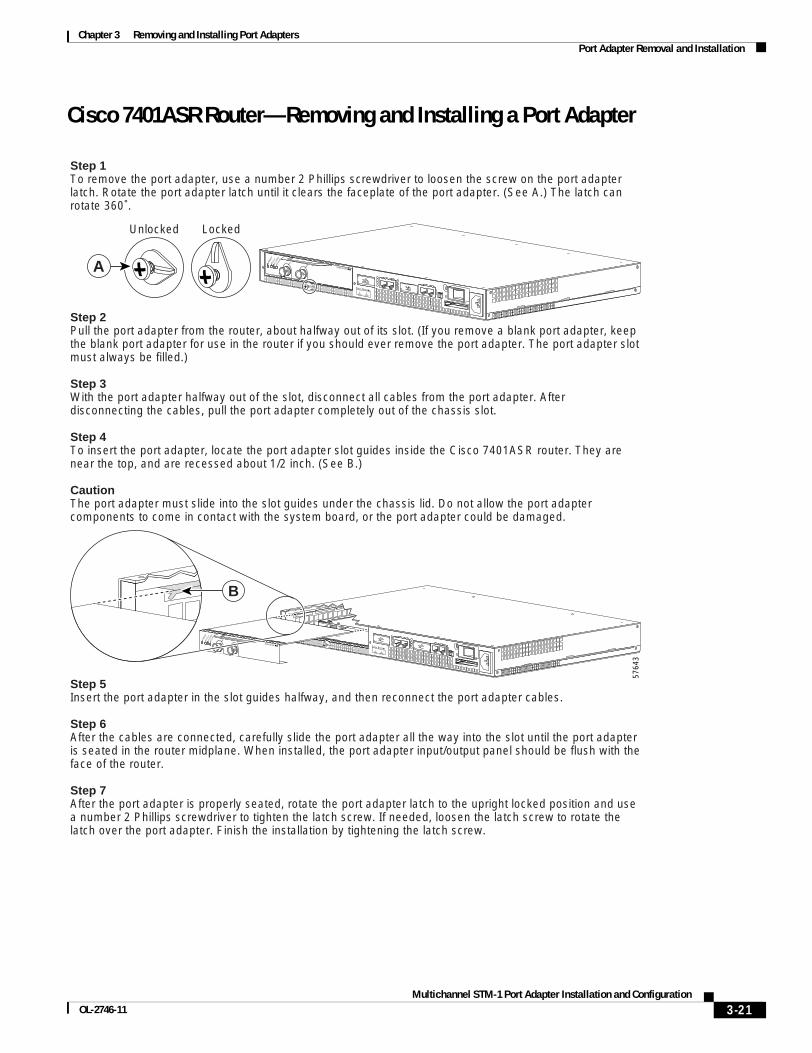
Chapter 3 Removing and Installing Port Adapters Port Adapter Removal and Installation
Cisco 7401ASR Router—Removing and Installing a Port Adapter
5764
3
Step 1To remove the port adapter, use a number 2 Phillips screwdriver to loosen the screw on the port adapter latch. Rotate the port adapter latch until it clears the faceplate of the port adapter. (See A.) The latch can rotate 360˚.
Step 2Pull the port adapter from the router, about halfway out of its slot. (If you remove a blank port adapter, keep the blank port adapter for use in the router if you should ever remove the port adapter. The port adapter slot must always be filled.)
Step 3With the port adapter halfway out of the slot, disconnect all cables from the port adapter. After disconnecting the cables, pull the port adapter completely out of the chassis slot.
Step 4To insert the port adapter, locate the port adapter slot guides inside the Cisco 7401ASR router. They are near the top, and are recessed about 1/2 inch. (See B.)
CautionThe port adapter must slide into the slot guides under the chassis lid. Do not allow the port adapter components to come in contact with the system board, or the port adapter could be damaged.
Step 5Insert the port adapter in the slot guides halfway, and then reconnect the port adapter cables.
Step 6After the cables are connected, carefully slide the port adapter all the way into the slot until the port adapter is seated in the router midplane. When installed, the port adapter input/output panel should be flush with the face of the router.
Step 7After the port adapter is properly seated, rotate the port adapter latch to the upright locked position and use a number 2 Phillips screwdriver to tighten the latch screw. If needed, loosen the latch screw to rotate the latch over the port adapter. Finish the installation by tightening the latch screw.
ENAB
LED
RX CE
LLS
RX CA
RRIER
RX AL
ARM
TX
RX ENHANCED ATM
ENAB
LED
RX CE
LLS
RX CA
RRIER
RX AL
ARM
TX
RX ENHANCED ATM
B
A
LockedUnlocked
3-21Multichannel STM-1 Port Adapter Installation and Configuration
OL-2746-11

Chapter 3 Removing and Installing Port Adapters Port Adapter Removal and Installation
Cisco 7500 Series Routers with VIP—Removing and Installing a Port Adapter
Note: You must first remove the VIP from the chassis before removing a port adapter from the VIP.
Step 1
To remove the port adapter, removethe screw that secures the portadapter (or blank port adapter).(See A.)
Step 2
With the screw removed, grasp the handle on the front of the port adapter (or blank port adapter) and carefully pull it out of its slot, away from the edge connector at the rear of the slot. (See A.)
Step 3
To insert the port adapter, carefully align the port adapter carrier between the upper and the lower edges of the port adapter slot. (See B.)
Step 4
Carefully slide the new port adapter into the port adapter slot until the connector on the port adapter is completely seated in the connector at the rear of the port adapter slot. (See B.)
Step 5
Install the screw in the rear of the port adapter slot on the VIP. Do not overtighten the screw. (See A.)
Step 6Carefully slide the VIP motherboard into the interface processor slot until the connectors at the rear of the VIP are completely seated in the connectors at the rear of the interface processor slot. Use the ejector levers to seat the VIP in the interface processor slot. Tighten the captive installation screws on the VIP. (See C.)
2652
0
Screw
Lower edge
Carrier
Upper edge
EJECT
SLOT 0SLO
T 1
NORMAL CPU HALT
RESET
AUX.
CONSOLE
ROUTE SWITCH PROCESSOR
A
B
C
Captiveinstallation
screw
3-22Multichannel STM-1 Port Adapter Installation and Configuration
OL-2746-11

Chapter 3 Removing and Installing Port Adapters Connecting a PA-MC-STM-1 Cable
Connecting a PA-MC-STM-1 CableTo continue your PA-MC-STM-1 port adapter installation, you must connect the interface cables. The instructions that follow apply to all supported platforms.
Note Optical fiber cables are not available from Cisco Systems; they are available from outside commercial cable vendors. (For more information on the cables you should use with this port adapter, see the “PA-MC-STM-1 Optical Fiber Specifications” section on page 1-5 and the “Cables, Connectors, and Pinouts” section on page 1-7.)
To connect cables to the PA-MC-STM-1, attach either one duplex optical fiber cable or two simplex optical fiber cables between the PA-MC-STM-1 interface port and your network. (See Figure 3-6.)
Note Ensure that you observe the proper relationship of receive (RX) cable to RX SC-type receptacle and transmit (TX) cable to TX SC-type receptacle on the PA-MC-STM-1.
Figure 3-6 Connecting Simplex or Duplex Optical Fiber Cables to the PA-MC-STM-1
Warning Invisible laser radiation may be emitted from the end of the unterminated fiber cable or connector. Do not view directly with optical instruments. Viewing the laser output with certain optical instruments (for example, eye loupes, magnifiers, and microscopes) within a distance of 100 mm may pose an eye hazard. Statement 1056
Warning Class 1 Laser Product. Statement 1008.
Warning Class 1 LED Product. Statement 1027.
This completes the procedure for replacing an optical fiber cable on the PA-MC-STM-1.
4725
3
ENABLEDRxC
XR
Alarm
PA-MC-STM-SMI
PRODUCTO LASER CLA
SE 1
1
PRODUIT LASER DE CLA
SSE 1
CLASS 1
LASER PRODUCT
LASERPRODUKT DER KLA
SSE 1
1 duplexconnector
(RX and TX)2 simplex
connectors
RX
TXor
RX TX
3-23Multichannel STM-1 Port Adapter Installation and Configuration
OL-2746-11

Chapter 3 Removing and Installing Port Adapters Connecting a PA-MC-STM-1 Cable
3-24Multichannel STM-1 Port Adapter Installation and Configuration
OL-2746-11

MultichanneOL-2746-11
C H A P T E R4
Configuring the PA-MC-STM-1To continue your PA-MC-STM-1 port adapter installation, you must configure the STM-1 interface. The instructions that follow apply to all supported platforms. Minor differences among the platforms—with Cisco IOS software commands—are noted.
This chapter contains the following sections:
• Using the EXEC Command Interpreter, page 4-1
• Configuring the Interface, page 4-2
• Checking the Configuration, page 4-13
Note The Cisco 7200 VXR Port Adapter Jacket Card requires no configuration. Configure a port adapter in it as you would any other port adapter.
Using the EXEC Command Interpreter You modify the configuration of your router or switch through the software command interpreter called the EXEC (also called enable mode). You must enter the privileged level of the EXEC command interpreter with the enable command before you can use the configure command to configure a new interface or change the existing configuration of an interface. The system prompts you for a password if one has been set.
The system prompt for the privileged level ends with a pound sign (#) instead of an angle bracket (>). At the console terminal, use the following procedure to enter the privileged level:
Step 1 At the user-level EXEC prompt, enter the enable command. The EXEC prompts you for a privileged-level password as follows:
Router> enable
Password:
Step 2 Enter the password (the password is case sensitive). For security purposes, the password is not displayed.
When you enter the correct password, the system displays the privileged-level system prompt (#):
Router#
4-1l STM-1 Port Adapter Installation and Configuration

Chapter 4 Configuring the PA-MC-STM-1 Configuring the Interface
Configuring the Interface After you verify that the new PA-MC-STM-1 is installed correctly (the ENABLED LED goes on), use the privileged-level configure command to configure the new interface. Have the following information available:
• Protocols you plan to route on each new interface
• IP addresses, if you plan to configure the interfaces for IP routing
• Bridging protocols you plan to use
If you installed a new PA-MC-STM-1 or if you want to change the configuration of an existing interface, you must enter configuration mode to configure the new interfaces. If you replaced a PA-MC-STM-1 that was previously configured, the system recognizes the new interfaces and brings each of them up in their existing configurations.
For a summary of the configuration options available and instructions for configuring interfaces on a PA-MC-STM-1, refer to the appropriate configuration publications listed in the “Related Documentation” section on page ix.
You execute configuration commands from the privileged level of the EXEC command interpreter, which usually requires password access. Contact your system administrator, if necessary, to obtain password access. (See the “Using the EXEC Command Interpreter” section on page 4-1 for an explanation of the privileged level of the EXEC.)
This section contains the following subsections:
• Shutting Down an Interface, page 4-2
• Performing a Basic Interface Configuration, page 4-6
• Configuring the AU-3s and TUG-3s of a PA-MC-STM-1, page 4-9
• Configuring a Logical Channel Group on an E1 Line, page 4-9
• Configuring a Logical Channel Group Interface, page 4-10
• Configuring an E1 Unframed Channel, page 4-10
• Basic Multi-Router MSP Configuration, page 4-10
• Basic Single Router APS Configuration, page 4-12
Shutting Down an Interface Before you remove an interface that you will not replace, or replace port adapters, use the shutdown command to shut down (disable) the interfaces to prevent anomalies when you reinstall the new or reconfigured port adapter. When you shut down an interface, it is designated administratively down in the show command displays.
Follow these steps to shut down an interface:
Step 1 Enter the privileged level of the EXEC command interpreter (also called enable mode). (See the “Using the EXEC Command Interpreter” section on page 4-1 for instructions.)
Step 2 At the privileged-level prompt, enter configuration mode and specify that the console terminal is the source of the configuration subcommands, as follows:
Router# configure terminalEnter configuration commands, one per line. End with CNTL/Z.Router(config)#
4-2Multichannel STM-1 Port Adapter Installation and Configuration
OL-2746-11

Chapter 4 Configuring the PA-MC-STM-1 Configuring the Interface
Step 3 Shut down interfaces by entering the interface serial subcommand (followed by the interface address of the interface), and then enter the shutdown command. Table 4-1 shows the command syntax.
When you have finished, press Ctrl-Z—hold down the Control key while you press Z—or enter end or exit to exit configuration mode and return to the EXEC command interpreter.
Table 4-1 shows the shutdown command syntax for the supported platforms.
Table 4-1 Syntax of the shutdown Command for the Supported Platforms
Platform Command Example
FlexWAN module in Catalyst 6000 family switches and Cisco 7600 series Internet Routers
interface, followed by the type (serial) module/bay/port (module-slot-number/port-adapter-bay-number/interface-port-number)
shutdown
The example is for interface 0 on a port adapter in module slot 5 in port adapter bay 0.
Console# interface serial 5/0/0Console# shutdownCtrl-ZConsole#
Cisco 7200 VXR routers interface, followed by the type (serial) and slot/port (port-adapter-slot-number/interface-port-number)
shutdown
The example is for interface 0 on a port adapter in port adapter slot 6.
Router(config-if)# interface serial 6/0Router(config-if)# shutdownCtrl-ZRouter#
Cisco 7201 router interface, followed by the type (serial) and slot/port (port-adapter-slot-number/interface-port-number)
shutdown
The example is for interface 0 and interface 1 on a port adapter in slot 1.
Router(config)# interface serial 1/0Router(config-if)# shutdownRouter(config-if)# interface serial 1/1Router(config-if)# shutdownCtrl-ZRouter#
Cisco 7301 router interface, followed by the type (serial) and slot/port (port-adapter-slot-number/interface-port-number)
shutdown
The example is for interface 0 and interface 1 on a port adapter in slot 1.
Router(config)# interface serial 1/0Router(config-if)# shutdownRouter(config-if)# interface serial 1/1Router(config-if)# shutdownCtrl-ZRouter#
Cisco 7304 PCI Port Adapter Carrier Card in a Cisco 7304 router
interface, followed by the type (serial) and slot/port (module-slot-number/interface-port-number)
shutdown
The example is for interface 0 on a port adapter in a Cisco 7304 PCI Port Adapter Carrier Card in module slot 3 of a Cisco 7304 router.
Router(config-if)# interface serial 3/0Router(config-if)# shutdownCtrl-ZRouter#
4-3Multichannel STM-1 Port Adapter Installation and Configuration
OL-2746-11

Chapter 4 Configuring the PA-MC-STM-1 Configuring the Interface
Note If you need to shut down additional interfaces, enter the interface serial command (followed by the interface address of the interface) for each of the interfaces on your port adapter. Use the no shutdown command to enable the interface.
Step 4 Write the new configuration to NVRAM as follows:
Router# copy running-config startup-config[OK]Router#
The system displays an OK message when the configuration has been stored in NVRAM.
Step 5 Verify that new interfaces are now in the correct state (shut down) using the show interfaces command (followed by the interface type and interface address of the interface) to display the specific interface.
Cisco 7401ASR router interface, followed by the type (serial) and slot/port (port-adapter-slot-number/interface-port-number)
shutdown
The example is for interface 0 and interface 1 on a port adapter in slot 1.
Router(config)# interface serial 1/0Router(config-if)# shutdownRouter(config-if)# interface serial 1/1Router(config-if)# shutdownCtrl-ZRouter#
VIP4-80 or VIP6-80 in Cisco 7500 series routers
interface, followed by the type (serial) and slot/port adapter/port (interface-processor-slot-number/port-adapter-slot-number/interface-port-number)
shutdown
The example is for interface 0 on a port adapter in port adapter slot 1 of a VIP installed in interface processor slot 1.
Router(config-if)# interface serial 1/1/0Router(config-if)# shutdownCtrl-ZRouter#
Table 4-1 Syntax of the shutdown Command for the Supported Platforms (continued)
Platform Command Example
4-4Multichannel STM-1 Port Adapter Installation and Configuration
OL-2746-11

Chapter 4 Configuring the PA-MC-STM-1 Configuring the Interface
Table 4-2 provides examples of the show interfaces serial command for the supported platforms.
Table 4-2 Examples of the show interfaces serial Command for the Supported Platforms
Platform Command Example
FlexWAN module in Catalyst 6000 family switches and Cisco 7600 series Internet Routers
show interfaces serial, followed by module/bay/port (module-slot-number/port-adapter-bay-number/interface-port-number)
The example is for interface 0 on a port adapter in module slot 5 in port adapter bay 0.
Console# show interfaces serial 5/0/0
Serial 5/0/0 is administratively down, line protocol is down
[Additional display text omitted from this example]
Cisco 7200 VXR routers show interfaces serial, followed by slot/port (port-adapter-slot-number/interface-port-number)
The example is for interface 0 on a port adapter in port adapter slot 6.
Router# show interfaces serial 6/0
Serial 6/0 is administratively down, line protocol is down
[Additional display text omitted from this example]
Cisco 7201 router show interfaces serial, followed by slot/port (port-adapter-slot-number/interface-port-number)
The example is for interface 0 on a port adapter in port adapter slot 1.
Router# show interfaces serial 1/0
Serial 1/0 is administratively down, line protocol is down
[Additional display text omitted from this example]
Cisco 7301 router interface, followed by the type (serial) and slot/port (port-adapter-slot-number/interface-port-number)
The example is for interface 0 and interface 1 on a port adapter in slot 1.
Router(config)# interface serial 1/0Router(config-if)# shutdownRouter(config-if)# interface serial 1/1Router(config-if)# shutdownCtrl-ZRouter#
Cisco 7304 PCI Port Adapter Carrier Card in a Cisco 7304 router
show interfaces serial, followed by slot/port (module-slot-number/interface-port-number)
The example is for interface 0 on a port adapter in a Cisco 7304 PCI Port Adapter Carrier Card in module slot 3 of a Cisco 7304 router.
Router# show interfaces serial 3/0
Serial 3/0 is administratively down, line protocol is down
[Additional display text omitted from this example]
4-5Multichannel STM-1 Port Adapter Installation and Configuration
OL-2746-11
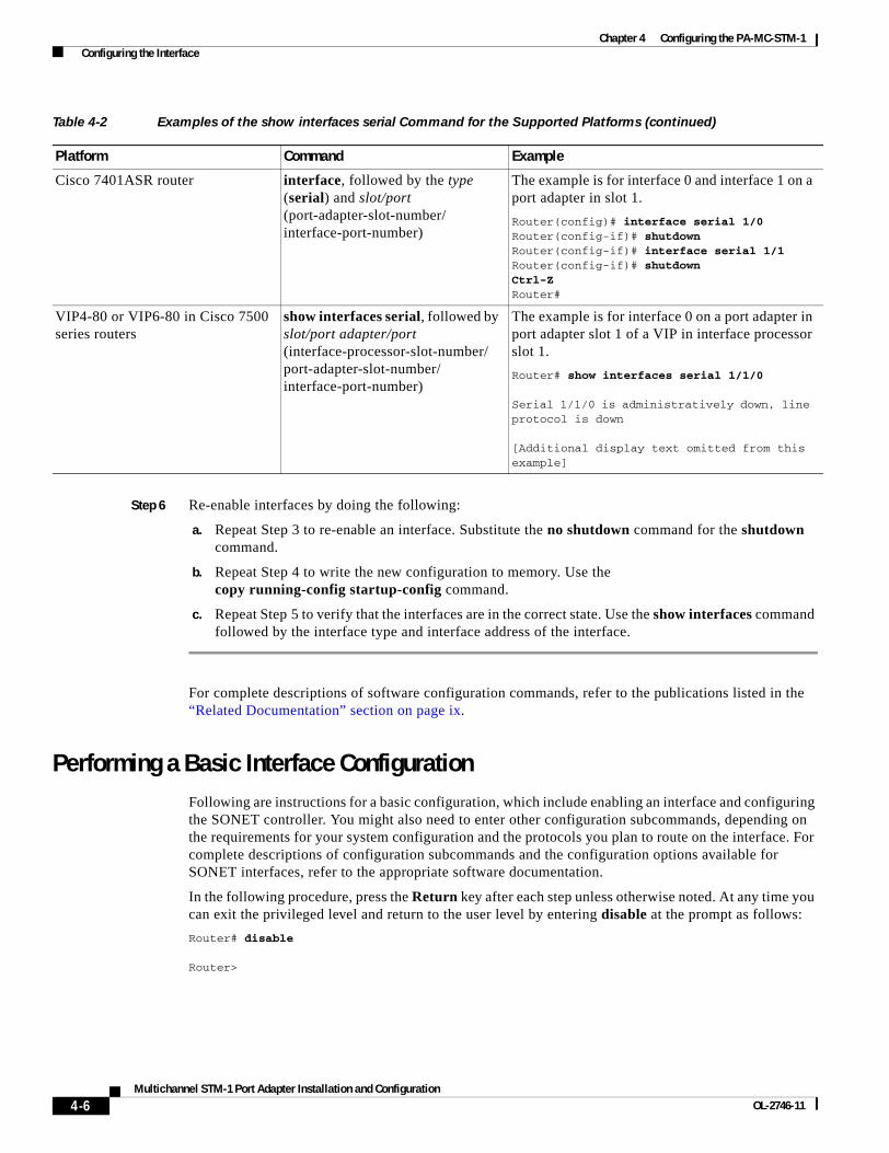
Chapter 4 Configuring the PA-MC-STM-1 Configuring the Interface
Step 6 Re-enable interfaces by doing the following:
a. Repeat Step 3 to re-enable an interface. Substitute the no shutdown command for the shutdown command.
b. Repeat Step 4 to write the new configuration to memory. Use the copy running-config startup-config command.
c. Repeat Step 5 to verify that the interfaces are in the correct state. Use the show interfaces command followed by the interface type and interface address of the interface.
For complete descriptions of software configuration commands, refer to the publications listed in the “Related Documentation” section on page ix.
Performing a Basic Interface Configuration Following are instructions for a basic configuration, which include enabling an interface and configuring the SONET controller. You might also need to enter other configuration subcommands, depending on the requirements for your system configuration and the protocols you plan to route on the interface. For complete descriptions of configuration subcommands and the configuration options available for SONET interfaces, refer to the appropriate software documentation.
In the following procedure, press the Return key after each step unless otherwise noted. At any time you can exit the privileged level and return to the user level by entering disable at the prompt as follows:
Router# disable
Router>
Cisco 7401ASR router interface, followed by the type (serial) and slot/port (port-adapter-slot-number/interface-port-number)
The example is for interface 0 and interface 1 on a port adapter in slot 1.
Router(config)# interface serial 1/0Router(config-if)# shutdownRouter(config-if)# interface serial 1/1Router(config-if)# shutdownCtrl-ZRouter#
VIP4-80 or VIP6-80 in Cisco 7500 series routers
show interfaces serial, followed by slot/port adapter/port (interface-processor-slot-number/port-adapter-slot-number/interface-port-number)
The example is for interface 0 on a port adapter in port adapter slot 1 of a VIP in interface processor slot 1.
Router# show interfaces serial 1/1/0
Serial 1/1/0 is administratively down, line protocol is down
[Additional display text omitted from this example]
Table 4-2 Examples of the show interfaces serial Command for the Supported Platforms (continued)
Platform Command Example
4-6Multichannel STM-1 Port Adapter Installation and Configuration
OL-2746-11

Chapter 4 Configuring the PA-MC-STM-1 Configuring the Interface
Step 1 Enter configuration mode and specify that the console terminal is the source of the configuration subcommands, as follows:
Router# configure terminalEnter configuration commands, one per line. End with CNTL/Z.Router(config)#
Step 2 Configure the SONET controller by entering the controller sonet subcommand, followed by the interface address of the controller you plan to configure.
Table 4-3 provides examples of the controller sonet subcommand for the supported platforms.
Table 4-3 Examples of the controller sonet Subcommand for the Supported Platforms
Platform Command Example
FlexWAN module in Catalyst 6000 family switches and Cisco 7600 series Internet Routers
controller sonet, followed by module/bay/port (module-slot-number/port-adapter-bay-number/interface-port-number)
The example is for interface 0 on a port adapter in module slot 5 in port adapter bay 0.
Console# controller sonet 5/0/0Console#
Cisco 7200 VXR routers controller sonet, followed by slot/port (port-adapter-slot-number/interface-port-number)
The example is for interface 0 of aport adapter in port adapter slot 6.
Router(config)# controller sonet 6/0Router(config-if)#
Cisco 7201 router controller sonet, followed by slot/port (port-adapter-slot-number/interface-port-number)
The example is for interface 0 of aport adapter in port adapter slot 1.
Router(config)# controller sonet 1/0Router(config-if)#
Cisco 7301 router controller sonet, followed by slot/port (port-adapter-slot-number/interface-port-number)
The example is for interface 0 of aport adapter in port adapter slot 1.
Router(config)# controller sonet 1/0Router(config-if)#
Cisco 7304 PCI Port Adapter Carrier Card in a Cisco 7304 router
controller sonet, followed by slot/port (module-slot-number/interface-port-number)
The example is for interface 0 on a port adapter in a Cisco 7304 PCI Port Adapter Carrier Card in module slot 3 of a Cisco 7304 router.
Router(config)# controller sonet 3/0Router(config-if)#
Cisco 7401ASR router controller sonet, followed by slot/port (port-adapter-slot-number/interface-port-number)
The example is for interface 0 of aport adapter in port adapter slot 1.
Router(config)# controller sonet 1/0Router(config-if)#
VIP4-80 or VIP6-80 in Cisco 7500 series routers
controller sonet, followed by slot/port adapter/port (interface-processor-slot-number/port-adapter-slot-number/interface-port-number)
The example is for interface 0 in port adapter slot 1 of a VIP in interface processor slot 1.
Router(config)# controller sonet 1/1/0Router(config-controller)#
4-7Multichannel STM-1 Port Adapter Installation and Configuration
OL-2746-11

Chapter 4 Configuring the PA-MC-STM-1 Configuring the Interface
Step 3 Use the framing {sonet | sdh} command to set the port to SONET mode or SDH mode, as shown below:
Router(config)# controller sonet 1/1/0Router(config-controller)# framing sdh
The default is SONET mode.
Step 4 Use the clock source {internal | line} command to determine if clocking will be obtained locally from the PA-MC-STM-1 or from the network or line, as shown below:
Router(config)# controller sonet 1/1/0Router(config-controller)# clock source internal
The default is line.
Step 5 Use the aug mapping {au-3 | au-4} command to determine how the administrative unit groups (AUGs) will be mapped. (See Figure 4-1.) The example shown below configures the AUG as AU-3:
Router(config)# controller sonet 1/1/0Router(config-controller)# aug mapping au-3
When the AUG is configured to be AU-3, the following muxing, alignment, and mapping will be configured:
C-12 <--> VC-12 <--> TU-12 <--> TUG-2 <--> VC-3 <--> AU-3 <--> AUG
When the AUG is configured to be AU-4, the following muxing, alignment, mapping will be configured:
C-12 <--> VC-12 <--> TU-12 <--> TUG-2 <--> TUG-3 <--> VC-4 <--> AU-4 <--> AUG
Note This command is available only when SDH framing is configured
Step 6 After including all of the configuration subcommands to complete your configuration, press Ctrl-Z—hold down the Control key while you press Z—or enter end or exit to exit configuration mode and return to the EXEC command interpreter prompt.
Step 7 Write the new configuration to NVRAM as follows:
Router# copy running-config startup-config[OK]Router#
This completes the procedure for creating a basic configuration.
4-8Multichannel STM-1 Port Adapter Installation and Configuration
OL-2746-11

Chapter 4 Configuring the PA-MC-STM-1 Configuring the Interface
Configuring the AU-3s and TUG-3s of a PA-MC-STM-1You can configure each of the administrative unit groups (AUGs) and tributary unit groups (TUGs) of a PA-MC-STM-1 to carry a set of E1 links that are mapped into TU-12s (see Figure 4-1).
Figure 4-1 PA-MC-STM-1 Multiplexing Structure
In the following example, SDH framing, internal clock source, AUG mapping au-4, and idle pattern are configured:
Router(config)# controller sonet 1/1/0Router(config-controller)# framing sdhRouter(config-controller)# clock source internalRouter(config-controller)# aug mapping au-4Router(config-controller)# au-4 1 tug-3 2Router(config-controller-tug3)# mode c-12Router(config-controller-tug3)# tug-2 4 e1 channel-group 15 timeslots 1-5, 20-23Router(config-controller-tug3)# idle pattern 0X0Router(config-controller-tug3)# exitRouter(config-controller)# exit
Configuring a Logical Channel Group on an E1 LineTo configure a logical channel group on an E1 line, use the tug-2 tug-2# e1 e1# channel-group channel-group# timeslots list-of-timeslots command where:
• tug-2# is a value from 1 to 7
• e1# is a value from 1 to 3
• channel-group# is a value from 0 to 30
• list-of-timeslots can be a value from 1 to 31 or a combination of subranges within the range 1 to 31 (each subrange is a list of time slots that makes up the E1 line).
In the following example, logical channel group 15 on E1 line 1 is configured and channelized time slots 1 to 5 and 20 to 23 are assigned to the newly created logical channel group:
Router(config)# controller sonet 1/1/0Router(config-controller)# framing sdhRouter(config-controller)# aug mapping au-4Router(config-controller)# au-4 1 tug-3 2Router(config-controller-tug3)# mode c-12Router(config-controller-tug3)# tug-2 4 e1 1 channel-group 15 timeslots 1-5, 20-23Router(config-controller-tug3)# exitRouter(config-controller)# exit
TU-12
TUG-2
TUG-3
E12.048 Mbps
C-12
x1
x1
x3
x1
VC-12
VC-4
VC-3 AU-3
AUG
x1
AU-4x3
x3x7
x7
STM-1
4790
2
4-9Multichannel STM-1 Port Adapter Installation and Configuration
OL-2746-11

Chapter 4 Configuring the PA-MC-STM-1 Configuring the Interface
Configuring a Logical Channel Group InterfaceOnce a channel group has been created (see the “Configuring a Logical Channel Group on an E1 Line” section on page 4-9), interface serial configuration commands may be used as in the example below:
Router(config)# controller sonet 1/1/0Router(config-controller)# framing sdhRouter(config-controller)# aug mapping au-4Router(config-controller)# au-4 1 tug-3 2Router(config-controller-tug3)# mode c-12Router(config-controller-tug3)# tug-2 4 e1 1 channel-group 15 timeslots 1-5, 20-23Router(config-controller-tug3)# exitRouter(config-controller)# exitRouter(config)# interface serial 1/1/0.1/2/4/1:15Router(config-if)# ip address 1.1.1.10 255.255.255.252Router(config-if)# encapsulation ppp
Configuring an E1 Unframed ChannelTo create an unframed or clear channel logical channel group on an E1 line, use the tug-2 tug-2# e1 e1# unframed command, as shown in the example below:
Router(config)# controller sonet 1/1/0Router(config-controller)# au-4 1 tug-3 2Router(config-controller-tug3)# tug-2 4 e1 1 unframed
Note The channel group is always 0 for unframed E1 lines.
Basic Multi-Router MSP ConfigurationThe following example shows the configuration of Multiplex Section Protection (MSP) on router A and router B (see Figure 4-2). In this example, router A is configured with the working controller, and router B is configured with the protect controller. If the working controller on router A becomes unavailable, the connection will automatically switchover to the protect controller on router B. This configuration is typically used to protect against both line card and router failures.
Figure 4-2 Basic Multi-Router MSP Configuration
Router A
E 0/0
Working interface
SONET 1/0/0
SONET 3/0/0
SONETnetworkequipment
Add Drop Multiplexer (ADM)
E 0/0
Router BProtect interface
1580
56
4-10Multichannel STM-1 Port Adapter Installation and Configuration
OL-2746-11
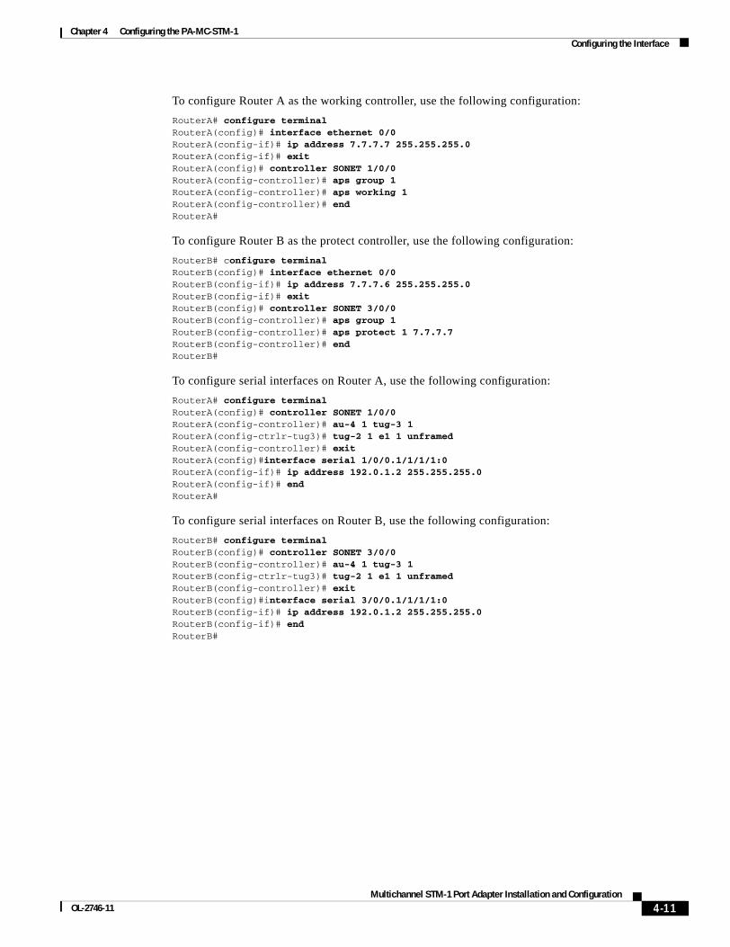
Chapter 4 Configuring the PA-MC-STM-1 Configuring the Interface
To configure Router A as the working controller, use the following configuration:
RouterA# configure terminalRouterA(config)# interface ethernet 0/0RouterA(config-if)# ip address 7.7.7.7 255.255.255.0RouterA(config-if)# exitRouterA(config)# controller SONET 1/0/0RouterA(config-controller)# aps group 1RouterA(config-controller)# aps working 1RouterA(config-controller)# endRouterA#
To configure Router B as the protect controller, use the following configuration:
RouterB# configure terminalRouterB(config)# interface ethernet 0/0RouterB(config-if)# ip address 7.7.7.6 255.255.255.0RouterB(config-if)# exitRouterB(config)# controller SONET 3/0/0RouterB(config-controller)# aps group 1RouterB(config-controller)# aps protect 1 7.7.7.7RouterB(config-controller)# endRouterB#
To configure serial interfaces on Router A, use the following configuration:
RouterA# configure terminalRouterA(config)# controller SONET 1/0/0RouterA(config-controller)# au-4 1 tug-3 1RouterA(config-ctrlr-tug3)# tug-2 1 e1 1 unframedRouterA(config-controller)# exitRouterA(config)#interface serial 1/0/0.1/1/1/1:0RouterA(config-if)# ip address 192.0.1.2 255.255.255.0RouterA(config-if)# endRouterA#
To configure serial interfaces on Router B, use the following configuration:
RouterB# configure terminalRouterB(config)# controller SONET 3/0/0RouterB(config-controller)# au-4 1 tug-3 1RouterB(config-ctrlr-tug3)# tug-2 1 e1 1 unframedRouterB(config-controller)# exitRouterB(config)#interface serial 3/0/0.1/1/1/1:0RouterB(config-if)# ip address 192.0.1.2 255.255.255.0RouterB(config-if)# endRouterB#
4-11Multichannel STM-1 Port Adapter Installation and Configuration
OL-2746-11

Chapter 4 Configuring the PA-MC-STM-1 Configuring the Interface
Basic Single Router APS ConfigurationThe following example shows the configuration of Automatic Protection Switching (APS) on router A (see Figure 4-3). In this example, Router A has both working and protect controllers. If the working controller SONET 1/0/0 becomes unavailable, the connection will automatically switchover to the protect controller SONET 3/0/0. Single router APS configuration is typically used to protect line card failures.
Figure 4-3 Basic Single Router APS Configuration
To configure a loopback interface on Router A, use the following configuration:
RouterA# configure terminalRouterA(config)# interface Loopback 0/0RouterA(config-if)# ip address 7.7.7.7 255.255.255.255RouterA(config-if)# endRouterA#
Next, to configure working and protect controllers, use the following configuration:
RouterA# configure terminalRouterA(config)# controller SONET 1/0/0RouterA(config-controller)# aps group 1RouterA(config-controller)# aps working 1RouterA(config-controller)# exitRouterA(config)# controller SONET 3/0/0RouterA(config-controller)# aps group 1RouterA(config-controller)# aps protect 1 7.7.7.7RouterA(config-controller)# endRouterA#
Finally, to configure serial interfaces on both working and protect controllers, use the following configuration:
RouterA(config)# controller SONET 1/0/0RouterA(config-controller)# au-4 1 tug-3 1RouterA(config-ctrlr-tug3)# tug-2 1 e1 1 unframedRouterA(config-controller)# exitRouterA(config)#interface serial 1/0/0.1/1/1/1:0RouterA(config-if)# ip address 192.0.1.2 255.255.255.0RouterA(config-if)# exitRouterA(config)# controller SONET 3/0/0RouterA(config-controller)# au-4 1 tug-3 1RouterA(config-ctrlr-tug3)# tug-2 1 e1 1 unframedRouterA(config-controller)# exitRouterA(config)#interface serial 3/0/0.1/1/1/1:0
Router A
SONET 1/0/0Working interface
SONET 3/0/0Protect interface
SONETnetworkequipment
Add Drop Multiplexer (ADM)
1580
61
4-12Multichannel STM-1 Port Adapter Installation and Configuration
OL-2746-11
Chapter 4 Configuring the PA-MC-STM-1 Checking the Configuration
RouterA(config-if)# ip address 192.0.1.2 255.255.255.0RouterA(config-if)# end
Note MSP is only supported at the SONET controller level. Individual E1 level protection is not supported with PA-MC-STM1.
Checking the Configuration After configuring the new interface, use the show commands to display the status of the new interface or all interfaces, and use the ping and loopback commands to check connectivity. This section includes the following subsections:
• Using show Commands to Verify the New Interface Status, page 4-13
• Using the ping Command to Verify Network Connectivity, page 4-25
• Using loopback Commands, page 4-25
Using show Commands to Verify the New Interface StatusThis section demonstrates how you can use the show commands to verify that new interfaces are configured and operating correctly and that the module appears in them correctly. Sample displays of the output of selected show commands appear in the sections that follow. For complete command descriptions and examples, refer to the publications listed in the “Related Documentation” section on page ix.
If an interface is shut down and you configured it as up, or if the displays indicate that the hardware is not functioning properly, ensure that the interface is properly connected and terminated. If you still have problems bringing up the interface, contact a service representative for assistance.
This section includes the following subsections:
• Using the show controllers Commands, page 4-14
• Using the show protocols Command, page 4-14
• Using the show running-config Command, page 4-15
• Using the show startup-config Command, page 4-15
• Using the show version or show hardware Commands, page 4-17
• Using the show diag Command, page 4-20
• Using the show interfaces Command, page 4-22
4-13Multichannel STM-1 Port Adapter Installation and Configuration
OL-2746-11

Chapter 4 Configuring the PA-MC-STM-1 Checking the Configuration
Using the show controllers Commands
Display all the current interface processors and their interfaces using the show controllers command.
Note The outputs that appear in this document may not match the output you receive when running these commands. The outputs in this document are examples only.
The following is an example of the show controllers command:
Router# show controllers
MEMD at 40000000, 2097152 bytes (unused 3360, recarves 1, lost 0) RawQ 48000100, ReturnQ 48000108, EventQ 48000110 BufhdrQ 48000128 (2900 items), LovltrQ 48000140 (5 items, 2016 bytes) IpcbufQ 48000150 (16 items, 4096 bytes) IpcbufQ_classic 48000148 (8 items, 4096 bytes) 3570 buffer headers (48002000 - 4800FF10) pool0: 9 buffers, 256 bytes, queue 48000130 pool1: 344 buffers, 1536 bytes, queue 48000138 pool2: 284 buffers, 4544 bytes, queue 48000158 pool3: 4 buffers, 4576 bytes, queue 48000160 slot2: VIP2, hw 2.4, sw 22.20, ccb 5800FF40, cmdq 48000090
software loaded from flash slot0:vip2_22-20.atmdx.191897 IOS (tm) VIP Software (SVIP-DW-M), Experimental Version 11.3
ROM Monitor version 17.0 ATM2/0/0, applique is DS3 (45Mbps)
gfreeq 48000158, lfreeq 48000168 (4544 bytes), throttled 0 rxlo 4, rxhi 284, rxcurr 1, maxrxcurr 5 txq 48001A00, txacc 48001A02 (value 284), txlimit 284
Using the show protocols Command
Display protocols configured for the entire system and for specific interfaces using the show protocols command.
Note The outputs that appear in this document may not match the output you receive when running these commands. The outputs in this document are examples only.
The following is an example of the show protocols command:
Router# show protocolsline protocol is up
4-14Multichannel STM-1 Port Adapter Installation and Configuration
OL-2746-11

Chapter 4 Configuring the PA-MC-STM-1 Checking the Configuration
Using the show running-config Command
Display the running configuration file using the show running-config command.
Note The outputs that appear in this document may not match the output you receive when running these commands. The outputs in this document are examples only.
The following is an example of the show running-config command:
Router# show running-config
Building configuration...Current configuration:!!!user add admin uid 0 capability admin-access!!!hostname CR4430!interface ethernet 0 ip address 10.2.2.8 255.255.255.0 ip broadcast-address 10.2.2.255 exit!interface ethernet 1 exit!ip default-gateway 10.2.2.1ip name-server 10.2.2.6ip route 0.0.0.0 0.0.0.0 10.2.2.1
Using the show startup-config Command
Display the configuration stored in the NVRAM using the show startup-config command.
Note The outputs that appear in this document may not match the output you receive when running these commands. The outputs in this document are examples only.
The following is an example of the show startup-config command:
Router# show startup-configBuilding configuration... Current configuration:!version 12.0service timestamps debug uptimeservice timestamps log uptimeno service password-encryption!hostname rp-3640-2b!ip subnet-zero!
4-15Multichannel STM-1 Port Adapter Installation and Configuration
OL-2746-11

Chapter 4 Configuring the PA-MC-STM-1 Checking the Configuration
ip audit notify logip audit po max-events 100!crypto isakmp policy 1hash md5 authentication pre-sharecrypto isakmp key cisco123 address 95.95.95.2 !crypto ipsec transform-set rtpset esp-des esp-md5-hmac !crypto map rtp 1 ipsec-isakmp set peer 95.95.95.2set transform-set rtpset match address 115!interface Ethernet0/0ip address 98.98.98.1 255.255.255.0no ip directed-broadcast!interface Ethernet0/1ip address 99.99.99.2 255.255.255.0no ip directed-broadcastno ip route-cacheno ip mroute-cachecrypto map rtp!interface Ethernet0/2no ip addressno ip directed-broadcastshutdown!interface Ethernet0/3no ip addressno ip directed-broadcastshutdown!ip classlessip route 0.0.0.0 0.0.0.0 99.99.99.1no ip http server!access-list 115 permit ip 98.98.98.0 0.0.0.255 10.103.1.0 0.0.0.255access-list 115 deny ip 98.98.98.0 0.0.0.255 any!line con 0transport input noneline aux 0line vty 0 4login!end
4-16Multichannel STM-1 Port Adapter Installation and Configuration
OL-2746-11

Chapter 4 Configuring the PA-MC-STM-1 Checking the Configuration
Using the show version or show hardware Commands
Display the configuration of the system hardware, the number of each interface type installed, the Cisco IOS software version, the names and sources of configuration files, and the boot images, using the show version (or show hardware) command.
Note The outputs that appear in this document may not match the output you receive when running these commands. The outputs in this document are examples only.
The following sections provide platform-specific output examples of the show version command:
• Catalyst 6000 Family Switches and Cisco 7600 Series Internet Routers with FlexWAN Module—Example Output of the show version Command, page 4-17
• Cisco 7200 VXR Routers—Example Output of the show version Command, page 4-18
• Cisco 7201 Router—Example Output of the show version Command, page 4-18
• Cisco 7500 Series Routers with VIP—Example Output of the show version Command, page 4-19
Catalyst 6000 Family Switches and Cisco 7600 Series Internet Routers with FlexWAN Module—Example Output of the show version Command
Following is an example of the show version command from a Catalyst 6000 family switch with a PA-MC-STM-1 installed:
Console# show version
Cisco Internetwork Operating System Software IOS (tm) MSFC Software (C6MSFC-JSV-M), Version 12.1(20010119:22010]Copyright (c) 1986-2001 by cisco Systems, Inc.Compiled Fri 19-Jan-01 14:46 by biffImage text-base: 0x60008950, data-base: 0x617AC000
ROM: System Bootstrap, Version 12.0(3)XE, RELEASE SOFTWARE BOOTFLASH: MSFC Software (C6MSFC-BOOT-M), Version 12.0(7)XE1, EARLY DEPLOYMENT )
Switch uptime is 4 hours, 21 minutesSystem returned to ROM by reloadSystem image file is "bootflash:c6msfc-jsv-mz.Feb9"
cisco Cat6k-MSFC (R5000) processor with 114688K/16384K bytes of memory.Processor board ID SAD03432638R5000 CPU at 200Mhz, Implementation 35, Rev 2.1, 512KB L2 CacheLast reset from power-onBridging software.X.25 software, Version 3.0.0.SuperLAT software (copyright 1990 by Meridian Technology Corp).TN3270 Emulation software.1 FlexWAN controller (1 Channelized OC3/STM-1).1 Virtual Ethernet/IEEE 802.3 interface(s)1 Channelized OC3/STM-1 port(s)123K bytes of non-volatile configuration memory.4096K bytes of packet SRAM memory. 16384K bytes of Flash internal SIMM (Sector size 256K).Configuration register is 0x100Cisco 7200 VXR Routers
4-17Multichannel STM-1 Port Adapter Installation and Configuration
OL-2746-11

Chapter 4 Configuring the PA-MC-STM-1 Checking the Configuration
Cisco 7200 VXR Routers—Example Output of the show version Command
Following is an example of the show version command from a Cisco 7200 VXR router with a PA-MC-STM-1 installed:
Router1-VXR> show version
Cisco Internetwork Operating System Software IOS (tm) 7200 Software (C7200-P-M), Version 12.1(20010104:023621) ]Copyright (c) 1986-2001 by cisco Systems, Inc.Compiled Tue 23-Jan-01 15:34 by biffImage text-base: 0x60008968, data-base: 0x60C56000
ROM: System Bootstrap, Version 12.0(20000211:194150)BOOTFLASH: 7200 Software (C7200-BOOT-M), Version 12.0(10)S, EARLY DEPLOYMENT RE)
Router1-VXR uptime is 5 days, 20 hours, 48 minutesSystem returned to ROM by reloadSystem image file is "c7200-p-mz"
cisco 7206VXR (NSE-1) processor (revision A) with 114688K/16384K bytes of memor.Processor board ID 21288237R7000 CPU at 262Mhz, Implementation 39, Rev 2.1, 256KB L2, 2000KB L3 Cache6 slot VXR midplane, Version 2.0
Last reset from power-onX.25 software, Version 3.0.0.PXF processor tmc is running.8 Ethernet/IEEE 802.3 interface(s)1 FastEthernet/IEEE 802.3 interface(s)63 Serial network interface(s)1 Channelized T3 port(s)1 Channelized OC3/STM-1 port(s)125K bytes of non-volatile configuration memory. 20480K bytes of Flash PCMCIA card at slot 0 (Sector size 128K).4096K bytes of Flash internal SIMM (Sector size 256K).Configuration register is 0x0
Cisco 7201 Router—Example Output of the show version Command
Following is an example of the show version command from a Cisco 7201 router:
Router# show version
Cisco IOS Software, 7200 Software (C7200P-ADVENTERPRISEK9-M), Version 12.4(biffDEV.061001), INTERIM SOFTWARE Copyright (c) 1986-2006 by Cisco Systems, Inc.Compiled Sun 01-Oct-06 23:42 by biffROM: System Bootstrap, Version 12.4(4r)XD5, RELEASE SOFTWARE (fc1)BOOTLDR: Cisco IOS Software, 7200 Software (C7200P-KBOOT-M), Version 12.4(TAZ3DEV.060927), INTERIM SOFTWAREc7201alpha1 uptime is 5 days, 18 hours, 32 minutes System returned to ROM by power-on System image file is "disk0:c7200p-adventerprisek9-mz.2006-10-01.biffdev"This product contains cryptographic features and is subject to United States and local country laws governing import, export, transfer and use. Delivery of Cisco cryptographic products does not imply third-party authority to import, export, distribute or use encryption.Importers, exporters, distributors and users are responsible for compliance with U.S. and local country laws. By using this product you agree to comply with applicable laws and regulations. If you are unable to comply with U.S. and local laws, return this product immediately.A summary of U.S. laws governing Cisco cryptographic products may be found at:
4-18Multichannel STM-1 Port Adapter Installation and Configuration
OL-2746-11

Chapter 4 Configuring the PA-MC-STM-1 Checking the Configuration
http://www.cisco.com/wwl/export/crypto/tool/stqrg.htmlIf you require further assistance please contact us by sending email to [email protected] 7201 (c7201) processor (revision A) with 917504K/65536K bytes of memory.Processor board ID 2222222222222MPC7448 CPU at 1666Mhz, Implementation 0, Rev 2.21 slot midplane, Version 2.255Last reset from power-on1 FastEthernet interface4 Gigabit Ethernet interfaces2045K bytes of NVRAM.62443K bytes of USB Flash usbflash0 (Read/Write)250880K bytes of ATA PCMCIA card at slot 0 (Sector size 512 bytes).65536K bytes of Flash internal SIMM (Sector size 512K).Configuration register is 0x2
Cisco 7500 Series Routers with VIP—Example Output of the show version Command
Following is an example of the show version command from a VIP4-80 in a Cisco 7500 series router with a PA-MC-STM-1 installed:
Router# show version
Cisco Internetwork Operating System Software IOS (tm) RSP Software (RSP-PV-M), Version 12.0(20000912:174226) ]Copyright (c) 1986-2000 by cisco Systems, Inc.Compiled Wed 13-Sep-00 04:08 by biffImage text-base: 0x60010950, data-base: 0x60DA6000
ROM: System Bootstrap, Version 11.1(8)CA1, RELEASE SOFTWARE (fc1)BOOTFLASH: GS Software (RSP-BOOT-M), Version 11.1(8)CA1, RELEASE SOFTWARE (fc1) 7500_right uptime is 2 minutesSystem returned to ROM by reload at 17:20:30 UTC Fri Apr 30 1999System image file is "tftp://223.255.254.254//tftpboot-users/halrev312sdevtst/rel091300/bin/rsp-pv-mz091300"
cisco RSP4 (R5000) processor with 131072K/2072K bytes of memory.R5000 CPU at 200Mhz, Implementation 35, Rev 2.1, 512KB L2 CacheLast reset from power-onG.703/E1 software, Version 1.0.G.703/JT2 software, Version 1.0.X.25 software, Version 3.0.0.1 EIP controller (6 Ethernet).1 VIP4-80 RM7000 controller (1 Channelized OC3/STM-1).6 Ethernet/IEEE 802.3 interface(s)1 Serial network interface(s)1 Channelized OC3/STM-1 port(s)123K bytes of non-volatile configuration memory.
20480K bytes of Flash PCMCIA card at slot 1 (Sector size 128K).8192K bytes of Flash internal SIMM (Sector size 256K).No slave installed in slot 7.Configuration register is 0x0
4-19Multichannel STM-1 Port Adapter Installation and Configuration
OL-2746-11
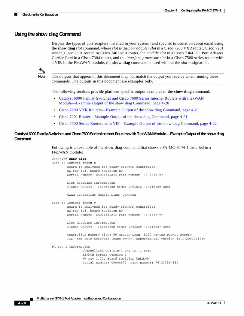
Chapter 4 Configuring the PA-MC-STM-1 Checking the Configuration
Using the show diag Command
Display the types of port adapters installed in your system (and specific information about each) using the show diag slot command, where slot is the port adapter slot in a Cisco 7200 VXR router, Cisco 7201 router, Cisco 7301 router, or Cisco 7401ASR router, the module slot in a Cisco 7304 PCI Port Adapter Carrier Card in a Cisco 7304 router, and the interface processor slot in a Cisco 7500 series router with a VIP. In the FlexWAN module, the show diag command is used without the slot designation.
Note The outputs that appear in this document may not match the output you receive when running these commands. The outputs in this document are examples only.
The following sections provide platform-specific output examples of the show diag command:
• Catalyst 6000 Family Switches and Cisco 7600 Series Internet Routers with FlexWAN Module—Example Output of the show diag Command, page 4-20
• Cisco 7200 VXR Routers—Example Output of the show diag Command, page 4-21
• Cisco 7201 Router—Example Output of the show diag Command, page 4-21
• Cisco 7500 Series Routers with VIP—Example Output of the show diag Command, page 4-22
Catalyst 6000 Family Switches and Cisco 7600 Series Internet Routers with FlexWAN Module—Example Output of the show diag Command
Following is an example of the show diag command that shows a PA-MC-STM-1 installed in a FlexWAN module:
Console# show diagSlot 4: Logical_index 8 Board is analyzed ipc ready FlexWAN controller HW rev 1.3, board revision B0 Serial Number: SAD04340JY3 Part number: 73-3869-07
Slot database information: Flags: 0x2004 Insertion time: 0x61BFC (04:16:29 ago)
CWAN Controller Memory Size: Unknown
Slot 4: Logical_index 9 Board is analyzed ipc ready FlexWAN controller HW rev 1.3, board revision B0 Serial Number: SAD04340JY3 Part number: 73-3869-07
Slot database information: Flags: 0x2004 Insertion time: 0x622A0 (04:16:27 ago)
Controller Memory Size: 56 MBytes DRAM, 8192 KBytes Packet Memory IOS (tm) cwlc Software (cwpa-DW-M), Experimental Version 12.1(20010119:v
PA Bay 1 Information: Channelized OC3/STM-1 SMI PA, 1 port EEPROM format version 4 HW rev 1.00, Board revision UNKNOWN Serial number: 00000000 Part number: 76-33356-130
4-20Multichannel STM-1 Port Adapter Installation and Configuration
OL-2746-11

Chapter 4 Configuring the PA-MC-STM-1 Checking the Configuration
Cisco 7200 VXR Routers—Example Output of the show diag Command
Following is an example of the show diag command that shows a PA-MC-STM-1 installed in port adapter slot 1 of a Cisco 7200 VXR router:
Router1-VXR> show diag 1Slot 1: Ethernet Port adapter, 8 ports Port adapter is analyzed Port adapter insertion time 5d20h ago EEPROM contents at hardware discovery: Hardware revision 1.14 Board revision A0 Serial number 16733712 Part number 255-65535-255 Test history 0x0 RMA number 255-255-255 EEPROM format version 1 EEPROM contents (hex): 0x20: 01 01 01 0E 00 FF 56 10 49 05 6F 08 00 00 00 00 0x30: 50 00 00 00 00 04 29 00 FF FF FF FF FF FF FF FF
Note Port adapters used with Cisco 7200 VXR routers require the correct base hardware revision in order to function. An error message occurs on bootup if the incorrect hardware revision is used. Use the show diag command to display the hardware revision.
Cisco 7201 Router—Example Output of the show diag Command
Following is an example of the show diag command from a Cisco 7201 router:
Router# show diag 1Slot 1:
Dual OC3 POS Port adapter, 2 portsPort adapter is analyzed Port adapter insertion time 00:02:19 agoEEPROM contents at hardware discovery:Hardware Revision : 1.0PCB Serial Number : JAE07520DYLPart Number : 73-8220-02Board Revision : A0RMA Test History : 00RMA Number : 0-0-0-0RMA History : 00Deviation Number : 0Product (FRU) Number : PA-POS-2OC3Top Assy. Part Number : 800-21857-02EEPROM format version 4EEPROM contents (hex):
0x00: 04 FF 40 03 E3 41 01 00 C1 8B 4A 41 45 30 37 350x10: 32 30 44 59 4C 82 49 20 1C 02 42 41 30 03 00 810x20: 00 00 00 00 04 00 88 00 00 00 00 CB 94 50 41 2D0x30: 50 4F 53 2D 32 4F 43 33 20 20 20 20 20 20 20 200x40: 20 C0 46 03 20 00 55 61 02 FF FF FF FF FF FF FF0x50: FF FF FF FF FF FF FF FF FF FF FF FF FF FF FF FF0x60: FF FF FF FF FF FF FF FF FF FF FF FF FF FF FF FF0x70: FF FF FF FF FF FF FF FF FF FF FF FF FF FF FF FF
4-21Multichannel STM-1 Port Adapter Installation and Configuration
OL-2746-11

Chapter 4 Configuring the PA-MC-STM-1 Checking the Configuration
Cisco 7500 Series Routers with VIP—Example Output of the show diag Command
Following is an example of the show diag command that shows a PA-MC-STM-1 installed in port adapter slot 2 on a VIP4-80 in interface processor slot 0:
Router# show diag 2Slot 2:
Physical slot 2, ~physical slot 0xD, logical slot 2, CBus 0Microcode Status 0x4Master Enable, LED, WCS LoadedBoard is analyzed Pending I/O Status: NoneEEPROM format version 1VIP4-80 RM7000 controller, HW rev 2.02, board revision B0Serial number: 18314858 Part number: 73-3143-02Test history: 0x00 RMA number: 00-00-00Flags: cisco 7000 board; 7500 compatibleEEPROM contents (hex): 0x20: 01 22 02 02 01 17 76 6A 49 0C 47 02 00 00 00 00 0x30: 58 00 00 00 00 00 00 00 00 00 00 00 00 00 00 00
Slot database information:Flags: 0x4Insertion time: 0x1DB8 (00:02:13 ago)
Controller Memory Size: 64 MBytes DRAM, 65536 KBytes SRAM
PA Bay 0 Information:Channelized OC3/STM-1 MM PA, 1 portEEPROM format version 4
HW rev 1.00, Board revision 04Serial number: MIC043626TF Part number: 73-4762-03
Using the show interfaces Command
Display status information (including the physical slot and interface address) for the interfaces you specify using the show interfaces command.
For complete descriptions of interface subcommands and the configuration options available for the supported interfaces, refer to the publications listed in the “Related Documentation” section on page ix.
Note The outputs that appear in this document may not match the output you receive when running these commands. The outputs in this document are examples only.
The following sections provide platform-specific output examples of the show interfaces command:
• Catalyst 6000 Family Switches and Cisco 7600 Series Internet Routers with FlexWAN Module—Example Output of the show interfaces Command, page 4-23
• Cisco 7200 VXR Routers—Example Output of the show interfaces Command, page 4-23
• Cisco 7201 Router—Example Output of the show interfaces Command, page 4-24
• Cisco 7500 Series Routers with VIP—Example Output of the show interfaces Command, page 4-24
4-22Multichannel STM-1 Port Adapter Installation and Configuration
OL-2746-11

Chapter 4 Configuring the PA-MC-STM-1 Checking the Configuration
Catalyst 6000 Family Switches and Cisco 7600 Series Internet Routers with FlexWAN Module—Example Output of the show interfaces Command
Following is an example of the show interfaces command that shows a PA-MC-STM-1installed in a FlexWAN module:
Console# show interfacesVlan1 is up, line protocol is up Hardware is Cat6k RP Virtual Ethernet
MTU 1500 bytes, BW 1000000 Kbit, DLY 10 usec, reliability 255/255, txload 1/255, rxload 1/255
Encapsulation ARPA, loopback not set ARP type: ARPA, ARP Timeout 04:00:00 Last input 00:00:00, output never, output hang never Last clearing of "show interface" counters never Queueing strategy: fifo Output queue 0/40, 0 drops; input queue 0/75, 0 drops 5 minute input rate 0 bits/sec, 2 packets/sec 5 minute output rate 0 bits/sec, 0 packets/sec 30459 packets input, 2875285 bytes, 0 no buffer Received 30419 broadcasts, 0 runts, 0 giants, 0 throttles 0 input errors, 0 CRC, 0 frame, 0 overrun, 0 ignored 343 packets output, 110047 bytes, 0 underruns 0 output errors, 1 interface resets 0 output buffer failures, 0 output buffers swapped out
Cisco 7200 VXR Routers—Example Output of the show interfaces Command
Following is an example of the show interfaces serial command that shows all of the information specific to interface port 0 on a PA-MC-STM-1 installed in port adapter slot 1 of a Cisco 7200 VXR router:
Router1-VXR> show interfaces serial 1/0.1/1/1/1:0Serial1/0.1/1/1/1:0 is up, line protocol is up Hardware is Channelized STM-1 controller MTU 1500 bytes, BW 1984 Kbit, DLY 20000 usec, reliability 255/255, txload 1/255, rxload 1/255 Encapsulation HDLC, crc 16, loopback not set Keepalive set (10 sec) Last input 00:00:01, output 00:00:06, output hang never Last clearing of "show interface" counters never Input queue: 0/75/0/0 (size/max/drops/flushes); Total output drops: 0 Queueing strategy: weighted fair Output queue: 0/1000/64/0 (size/max total/threshold/drops) Conversations 0/1/16 (active/max active/max total) Reserved Conversations 0/0 (allocated/max allocated) 5 minute input rate 0 bits/sec, 0 packets/sec 5 minute output rate 0 bits/sec, 0 packets/sec 50594 packets input, 1216008 bytes, 3 no buffer Received 0 broadcasts, 0 runts, 0 giants, 0 throttles 223 input errors, 24 CRC, 75 frame, 0 overrun, 0 ignored, 124 abort 59092 packets output, 6639740 bytes, 0 underruns 0 output errors, 0 collisions, 0 interface resets 0 output buffer failures, 0 output buffers swapped out 0 carrier transitions no alarm present
4-23Multichannel STM-1 Port Adapter Installation and Configuration
OL-2746-11

Chapter 4 Configuring the PA-MC-STM-1 Checking the Configuration
Cisco 7201 Router—Example Output of the show interfaces Command
Following is an example of the show interfaces command for the Cisco 7201 router:
Router# show interfaces
GigabitEthernet0/0 is up, line protocol is up Hardware is MV64460 Internal MAC, address is 0019.56c5.2adb (bia0019.56c5.2adb) Internet address is 209.165.200.225 MTU 1500 bytes, BW 1000000 Kbit, DLY 10 usec, reliability 255/255, txload 1/255, rxload 45/255 Encapsulation ARPA, loopback not set Keepalive set (10 sec) Full-duplex, 1000Mb/s, media type is RJ45 output flow-control is XON, input flow-control is XON ARP type: ARPA, ARP Timeout 04:00:00 Last input 00:07:03, output 00:00:07, output hang never Last clearing of "show interface" counters 00:00:04 Input queue: 0/75/0/0 (size/max/drops/flushes); Total output drops: 0 Queueing strategy: fifo Output queue: 0/40 (size/max) 5 minute input rate 180240000 bits/sec, 430965 packets/sec 5 minute output rate 0 bits/sec, 0 packets/sec 2222975 packets input, 133378500 bytes, 0 no buffer Received 0 broadcasts, 0 runts, 0 giants, 0 throttles 0 input errors, 0 CRC, 0 frame, 0 overrun, 0 ignored 0 watchdog, 0 multicast, 0 pause input 0 input packets with dribble condition detected 0 packets output, 0 bytes, 0 underruns 0 output errors, 0 collisions, 0 interface resets 0 babbles, 0 late collision, 0 deferred 0 lost carrier, 0 no carrier, 0 pause output 0 output buffer failures, 0 output buffers swapped out
Cisco 7500 Series Routers with VIP—Example Output of the show interfaces Command
Following is an example of the show interfaces serial command used with a VIP. In this example, the PA-MC-STM-1 is installed in port adapter slot 0 of a VIP in interface processor slot 2.
Router# show interfaces serial 2/0/0.1/1/1/1:1
Serial2/0/0.1/1/1/1:1 is up, line protocol is up Hardware is cyBus Channelized OC3/STM-1 PAInternet address is 105.105.105.1/24MTU 1500 bytes, BW 1984 Kbit, DLY 20000 usec, rely 255/255, load 36/255Encapsulation HDLC, loopback not setKeepalive not setLast input 00:00:00, output 00:00:00, output hang neverLast clearing of "show interface" counters neverInput queue: 1/75/0 (size/max/drops); Total output drops: 0Queueing strategy: weighted fairOutput queue: 0/1000/64/0 (size/max total/threshold/drops) Conversations 0/1/256 (active/max active/max total)Reserved Conversations 0/0 (allocated/max allocated)5 minute input rate 286000 bits/sec, 36 packets/sec5 minute output rate 284000 bits/sec, 36 packets/sec8019 packets input, 11695347 bytes, 0 no bufferReceived 0 broadcasts, 0 runts, 0 giants, 0 throttles0 input errors, 0 CRC, 0 frame, 0 overrun, 0 ignored, 0 abort7991 packets output, 11650799 bytes, 0 underruns0 output errors, 0 collisions, 0 interface resets
4-24Multichannel STM-1 Port Adapter Installation and Configuration
OL-2746-11

Chapter 4 Configuring the PA-MC-STM-1 Checking the Configuration
0 output buffer failures, 0 output buffers swapped out2 carrier transitions no alarm presentTimeslot(s) Used:1-31, Transmitter delay is 0 flags, transmit queue length 6[Additional display text for remaining interfaces omitted]
Proceed to the next section, “Using the ping Command to Verify Network Connectivity,” to check network connectivity of the PA-MC-STM-1 and switch or router.
Using the ping Command to Verify Network ConnectivityUsing the ping command, you can verify that an interface port is functioning properly. This section provides a brief description of this command. Refer to the publications listed in the “Related Documentation” section on page ix for detailed command descriptions and examples.
The ping command sends echo request packets out to a remote device at an IP address that you specify. After sending an echo request, the system waits a specified time for the remote device to reply. Each echo reply is displayed as an exclamation point (!) on the console terminal; each request that is not returned before the specified timeout is displayed as a period (.). A series of exclamation points (!!!!!) indicates a good connection; a series of periods (.....) or the messages [timed out] or [failed] indicate a bad connection.
Following is an example of a successful ping command to a remote server with the address 10.0.0.10:
Router# ping 10.0.0.10 <Return>Type escape sequence to abort.Sending 5, 100-byte ICMP Echoes to 10.0.0.10, timeout is 2 seconds:!!!!!Success rate is 100 percent (5/5), round-trip min/avg/max = 1/15/64 msRouter#
If the connection fails, verify that you have the correct IP address for the destination and that the device is active (powered on), and repeat the ping command.
Proceed to the next section, “Using loopback Commands,” to finish checking network connectivity.
Using loopback CommandsWith the loopback test, you can detect and isolate equipment malfunctions by testing the connection between the PA-MC-STM-1 interface and a remote device such as a multiplexer interface. The loopback subcommand places an interface in loopback mode, which enables test packets that are generated from the ping command to loop through a remote device. If the packets complete the loop, the connection is good. If not, you can isolate a fault to the remote device in the path of the loopback test.
The PA-MC-STM-1 supports two loopback modes at the sonet controller level: local and network.
Use the loopback {local | network} command to set the loopback mode, as shown below:
Router(config)# controller sonet 1/1/0Router(config-controller)# loopback network
When the loopback local command is used, all data transmitted to the network is internally looped back to the receiver. In this loopback mode, the serial interfaces should go into up/up looped state.
When the loopback network command is used, all data received from the connected device is transmitted back unchanged. In this loopback mode, T1 serial interfaces are not working.
The PA-MC-STM-1 also supports loopback on E1 lines mapped to a TUG-3 or AU-3.
4-25Multichannel STM-1 Port Adapter Installation and Configuration
OL-2746-11

Chapter 4 Configuring the PA-MC-STM-1 Checking the Configuration
To specify a loopback on an E1 line that has been mapped to a TUG-3, use the tug-2 e1 loopback command in configuration controller tug3 mode.
To specify a loopback on an E1 line that has been mapped to an AU-3, use the tug-2 e1 loopback command in configuration controller au3 mode.
The complete tug-2 e1 loopback command syntax is:
tug-2 tug-2 number e1 e1-number loopback {local | network {line | payload}}
To disable the loopback, use the no form of this command:
[no] tug-2 tug-2 number e1 e1-number loopback {local | network {line | payload}}
4-26Multichannel STM-1 Port Adapter Installation and Configuration
OL-2746-11