Embed Size (px)
Citation preview

1
Multiaxial and Thermomechanical Fatigue of Materials: A Historical Perspective and Some Future Challenges
Sreeramesh Kalluri Ohio Aerospace Institute
NASA Glenn Research CenterBrook Park, Ohio
Swedlow Memorial Lecture13th International ASTM/ESIS Symposium on Fatigue and Fracture
Mechanics (39th ASTM National Symposium on Fatigue and Fracture Mechanics)November 13-15, 2013, Jacksonville, Florida
https://ntrs.nasa.gov/search.jsp?R=20140000361 2018-05-13T11:41:39+00:00Z

2
Rationale for Multiaxial and Thermomechanical Fatigue
• Structural materials used in engineering applications routinely subjected to repetitive mechanical loads in multiple directions under non-isothermal conditions
• Over past few decades, several multiaxial fatigue life estimation models (stress- and strain-based) developed for isothermal conditions
• Historically, numerous fatigue life prediction models also developed for thermomechanical fatigue (TMF) life prediction, predominantly for uniaxial mechanical loading conditions
• Realistic structural components encounter multiaxial loads and non-isothermal loading conditions, which increase potential for interaction of damage modes. A need exists for mechanical testing and development & verification of life prediction models under such conditions.

3
Turbine
Typical Gas Turbine Engine Hot Section ComponentsCombustor Vane Turbine blade Turbine disk
4
PM Processed Nickel-Based Superalloy Disk
Realistic fatigue durability estimation of gas turbine engine components requires consideration of cyclic thermal and
multiaxial mechanical loads
Turbine disk subjected to thermal cycles and
multiaxial loads during start-ups and shutdowns
Finite element analysis revealing
stress concentrations at several locations
including the holes
Uncontained disk burst –Crack initiated from corner
of the hole

5
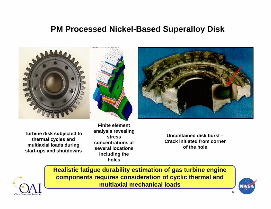
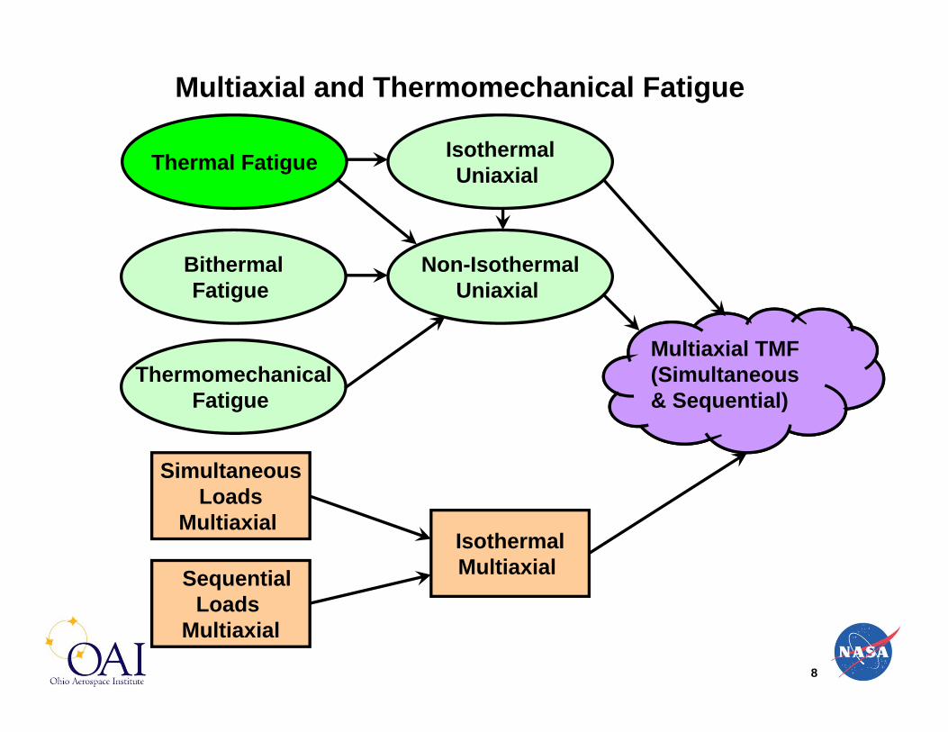
Multiaxial and Thermomechanical Fatigue
Thermal Fatigue
SimultaneousLoads
Multiaxial
SequentialLoads
Multiaxial
Multiaxial TMF(Simultaneous & Sequential)
BithermalFatigue
ThermomechanicalFatigue
Non-IsothermalUniaxial
IsothermalMultiaxial
IsothermalUniaxial

6
Multiaxial and Thermomechanical Fatigue - Scope
• Materials (metallic alloys, polymers, ceramics, composites, and materials with coatings)– Structural alloys for aerospace applications (uncoated)
• Fatigue crack initiation and fatigue crack growth– Fatigue crack initiation
• Low-cycle versus high-cycle fatigue– Low-cycle fatigue (primarily strain-based approaches)
• Deterministic versus probabilistic fatigue life estimation– Deterministic fatigue life estimation
• Multiaxial, thermomechanical fatigue – numerous possibilities– Some selected examples
• Future challenges in multiaxial thermomechanical fatigue– Cumulative fatigue, subcomponents, coatings, composite &
functionally graded materials, and residual stresses
7
Multiaxial and Thermomechanical Fatigue
Thermal Fatigue
SimultaneousLoads
Multiaxial
SequentialLoads
Multiaxial
Multiaxial TMF(Simultaneous & Sequential)
BithermalFatigue
ThermomechanicalFatigue
Non-IsothermalUniaxial
IsothermalMultiaxial
IsothermalUniaxial
8
Multiaxial and Thermomechanical Fatigue
Thermal Fatigue
SimultaneousLoads
Multiaxial
SequentialLoads
Multiaxial
Multiaxial TMF(Simultaneous & Sequential)
BithermalFatigue
ThermomechanicalFatigue
Non-IsothermalUniaxial
IsothermalMultiaxial
IsothermalUniaxial
9
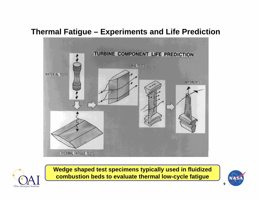
Thermal Fatigue – Experiments and Life Prediction
Wedge shaped test specimens typically used in fluidized combustion beds to evaluate thermal low-cycle fatigue

10
Thermal stresses developed during cycling generate inelastic strains, which lead to fatigue cracks
• Salient features– Thermal cycling
with an inherent constraint on deformation
– Typically limited or no externally imposed loads
– Mainly deformation controlled
Thermal Fatigue – Inelastic Strains and Cracking

11
Thermal Fatigue: Life Estimation Model
• Thermal fatigue– Inelastic strain range developed during the thermal cycle dictates the
fatigue life– Manson (1953) and Coffin (1954) working independently developed a
power law fatigue life relation
in = C(Nf)cManson-Coffin Equation:
References:
[1] Halford, G. R., “Low-Cycle Thermal Fatigue,” Thermal Stresses II, R. B. Hetnarsky (Ed.), Elsevier Science Publishers B.V., 1987, pp. 330-428.
[2] Sehitoglu, H., “Thermal and Thermomechanical Fatigue of Structural Alloys,” Fatigue and Fracture, ASM Handbook, Volume 19, 1996, pp. 527-556.
Where, in is inelastic strain range, Nf is fatigue life, C is the Coefficient, And c is the exponent

12
Multiaxial and Thermomechanical Fatigue
Thermal Fatigue
SimultaneousLoads
Multiaxial
SequentialLoads
Multiaxial
Multiaxial TMF(Simultaneous & Sequential)
BithermalFatigue
ThermomechanicalFatigue
Non-IsothermalUniaxial
IsothermalMultiaxial
IsothermalUniaxial
13
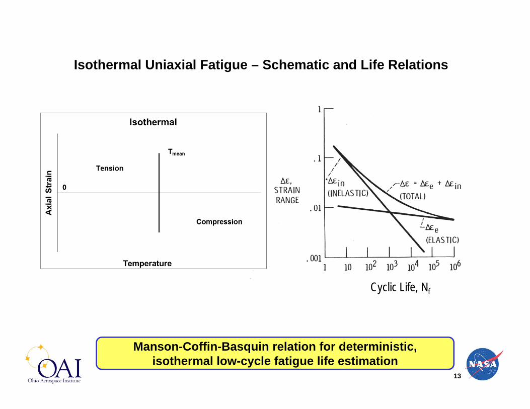
Isothermal Uniaxial Fatigue – Schematic and Life Relations
Manson-Coffin-Basquin relation for deterministic, isothermal low-cycle fatigue life estimation
Cyclic Life, Nf
14
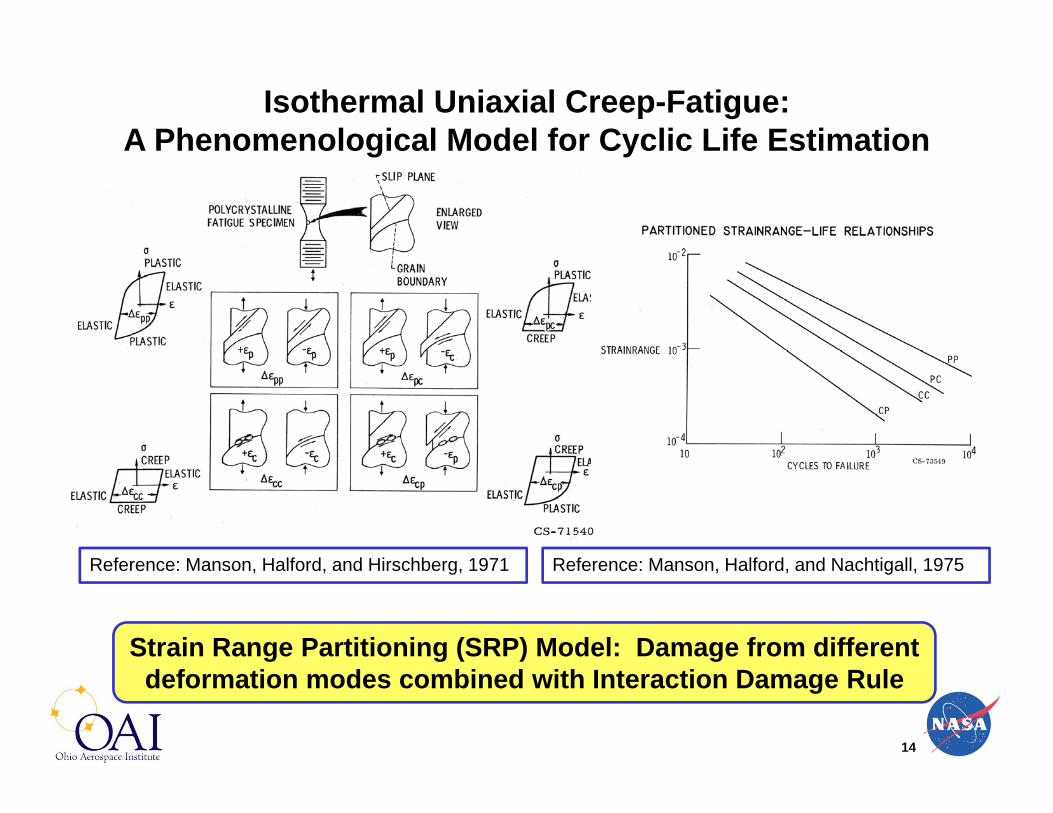
Isothermal Uniaxial Creep-Fatigue: A Phenomenological Model for Cyclic Life Estimation
Strain Range Partitioning (SRP) Model: Damage from different deformation modes combined with Interaction Damage Rule
Reference: Manson, Halford, and Hirschberg, 1971 Reference: Manson, Halford, and Nachtigall, 1975

15
Multiaxial and Thermomechanical Fatigue
Thermal Fatigue
SimultaneousLoads
Multiaxial
SequentialLoads
Multiaxial
Multiaxial TMF(Simultaneous & Sequential)
BithermalFatigue
ThermomechanicalFatigue
Non-IsothermalUniaxial
IsothermalMultiaxial
IsothermalUniaxial

16
Bithermal Uniaxial Fatigue: Schematics and Salient Features
• Salient features– Thermal cycling at two temperatures with externally imposed
loads– Free thermal expansion allowed during temperature changes– Effectively two isothermal segments of loading in tension and
compression– Load controlled with limits on deformation

17
Bithermal Uniaxial Creep-Fatigue: Schematic Hysteresis Loops
Originally conceived to impose creep in a short time and later viewed as a link between isothermal fatigue and TMF
Tensile Creep In-Phase
High Rate In-Phase
Compressive Creep Out-of-Phase
High Rate Out-of-Phase
References: Halford et al., ASTM STP 942, 1987 and Halford et al., ASTM STP 1122, 1991

18
Multiaxial and Thermomechanical Fatigue
Thermal Fatigue
SimultaneousLoads
Multiaxial
SequentialLoads
Multiaxial
Multiaxial TMF(Simultaneous & Sequential)
BithermalFatigue
ThermomechanicalFatigue
Non-IsothermalUniaxial
IsothermalMultiaxial
IsothermalUniaxial

19
• Salient Features– Simultaneous thermal and mechanical cycling– Externally imposed constraint on deformation– Temperature and deformation controlled– Additional complexity: thermal strain + mechanical strain
Thermomechanical Uniaxial Fatigue: Schematics and Salient Features

20
Uniaxial Thermomechanical Fatigue (TMF)• Phasing between mechanical strain and temperature
– Typically = 0° (in-phase) or = 180° (out-of-phase) [Carden and Slade, 1969]
– Clockwise and counter clockwise diamonds depending upon application
• Standards for uniaxial TMF testing– ASTM E 2368 (2010)– ISO FDIS-12111 (2012)
• TMF life estimation approaches– Phenomenological models and physical mechanism(s) based models– Creep, fatigue, creep-fatigue interaction and oxidation based models
• TMF deformation prediction methods– Plasticity and creep deformation models (non-unified)– Unified constitutive models
Reference: Sehitoglu, H., “Thermal and Thermomechanical Fatigue of Structural Alloys,” Fatigue and Fracture, ASM Handbook, Volume 19, 1996, pp. 527-556.

21
Experimental technique for determining creep strains within an in-phase thermomechanical hysteresis loop
Reference: Halford and Manson, ASTM STP 612, 1976
In-PhaseTMF Test( = 0°)
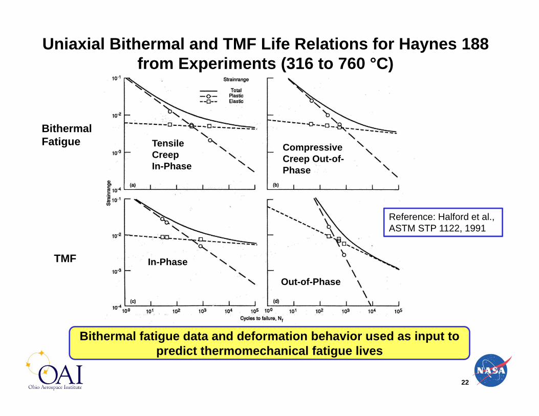
22
Bithermal fatigue data and deformation behavior used as input to predict thermomechanical fatigue lives
Uniaxial Bithermal and TMF Life Relations for Haynes 188 from Experiments (316 to 760 °C)
Reference: Halford et al., ASTM STP 1122, 1991
Tensile Creep In-Phase
Bithermal Fatigue Compressive
Creep Out-of-Phase
TMF In-Phase
Out-of-Phase

23
TMF Life Estimations from Bithermal Fatigue Data Using Total Strainrange SRP
TS-SRP Approach Estimations
Total strain range life curve is established for each specific type of TMF cycle using bithermal fatigue data and simplified flow equations
Reference: Halford et al., ASTM STP 1122, 1991

24
Multiaxial and Thermomechanical Fatigue
Thermal Fatigue
SimultaneousLoads
Multiaxial
SequentialLoads
Multiaxial
Multiaxial TMF(Simultaneous & Sequential)
BithermalFatigue
ThermomechanicalFatigue
Non-IsothermalUniaxial
IsothermalMultiaxial
IsothermalUniaxial
25
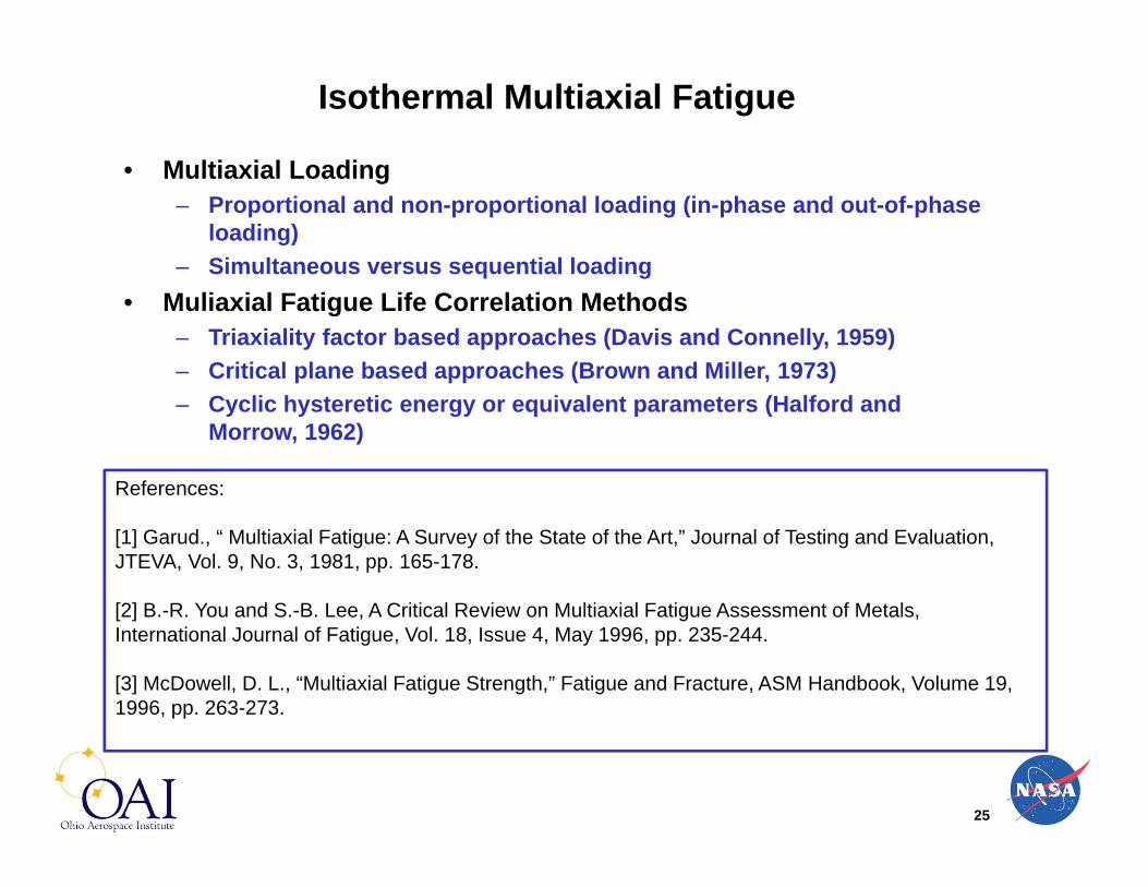
Isothermal Multiaxial Fatigue
References:
[1] Garud., “ Multiaxial Fatigue: A Survey of the State of the Art,” Journal of Testing and Evaluation, JTEVA, Vol. 9, No. 3, 1981, pp. 165-178.
[2] B.-R. You and S.-B. Lee, A Critical Review on Multiaxial Fatigue Assessment of Metals, International Journal of Fatigue, Vol. 18, Issue 4, May 1996, pp. 235-244.
[3] McDowell, D. L., “Multiaxial Fatigue Strength,” Fatigue and Fracture, ASM Handbook, Volume 19, 1996, pp. 263-273.
• Multiaxial Loading– Proportional and non-proportional loading (in-phase and out-of-phase
loading)– Simultaneous versus sequential loading
• Muliaxial Fatigue Life Correlation Methods– Triaxiality factor based approaches (Davis and Connelly, 1959)– Critical plane based approaches (Brown and Miller, 1973)– Cyclic hysteretic energy or equivalent parameters (Halford and
Morrow, 1962)

26
Isothermal Fatigue – Types of Multiaxial Loads• Axial, torsional, and combined axial-torsional loads
– Relatively simple form of multiaxial loading– Thin-walled tubular specimens (trade off between torsional buckling
and thin-wall to generate nearly uniform shear stress)– ASTM Standard E 2207 (2008)– ISO/FDIS 1352 (2011)
• Combined torsional and bending loads– Torque shafts in automotive applications– Relatively lower temperatures and typically high-cycle fatigue
• Combined biaxial loads– Thin-walled tubular specimens with internal and/or external pressure
(pressure vessels)– Cruciform specimens tested in-plane with four independent actuators
typically with centroid control• Combined triaxial loads
– 3-D version of a cruciform specimen (complicated design and most expensive to fabricate)
– Primary goal is to evaluate the influence of hydrostatic stress on fatigue life

27
Cruciform Specimen and In-plane Biaxial Test Rig
Thin-walled Tubular Specimen and Axial-Torsional Test Rig
Triaxial Cruciform Specimen for Creep
Rupture in Triaxial Tension
Source: Hayhurst and Felce (1985), Techniques for Multiaxial Creep Testing, D. J. Gooch and I. M. How (Eds.), Elsevier, 1986, p. 241
Examples of Multiaxial Test Specimens
References: Bartolotta, Ellis, and Abdul-Aziz, ASTM STP 1280, 1997 & Krause and Bartolotta, ASTM STP 1387, 2000
Reference: Kalluri and Bonacuse, ASTM STP 1092, 1990

28
Multiaxial and Thermomechanical Fatigue
Thermal Fatigue
SimultaneousLoads
Multiaxial
SequentialLoads
Multiaxial
Multiaxial TMF(Simultaneous & Sequential)
BithermalFatigue
ThermomechanicalFatigue
Non-IsothermalUniaxial
IsothermalMultiaxial
IsothermalUniaxial

29
Isothermal, Axial-Torsional, In- and Out-of-Phase Fatigue (Simultaneous Loading), = a a
In-Phase Out-of-Phase
Phase angle, = 0° Phase angle, = 75°
For out-of-phase tests, mechanical phase angle, = 90° is typical
30
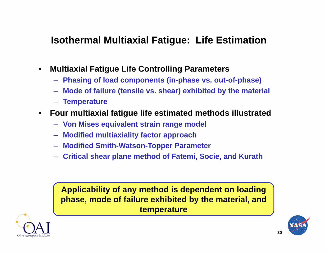
Isothermal Multiaxial Fatigue: Life Estimation
• Multiaxial Fatigue Life Controlling Parameters– Phasing of load components (in-phase vs. out-of-phase)– Mode of failure (tensile vs. shear) exhibited by the material– Temperature
• Four multiaxial fatigue life estimated methods illustrated– Von Mises equivalent strain range model– Modified multiaxiality factor approach– Modified Smith-Watson-Topper Parameter– Critical shear plane method of Fatemi, Socie, and Kurath
Applicability of any method is dependent on loading phase, mode of failure exhibited by the material, and
temperature
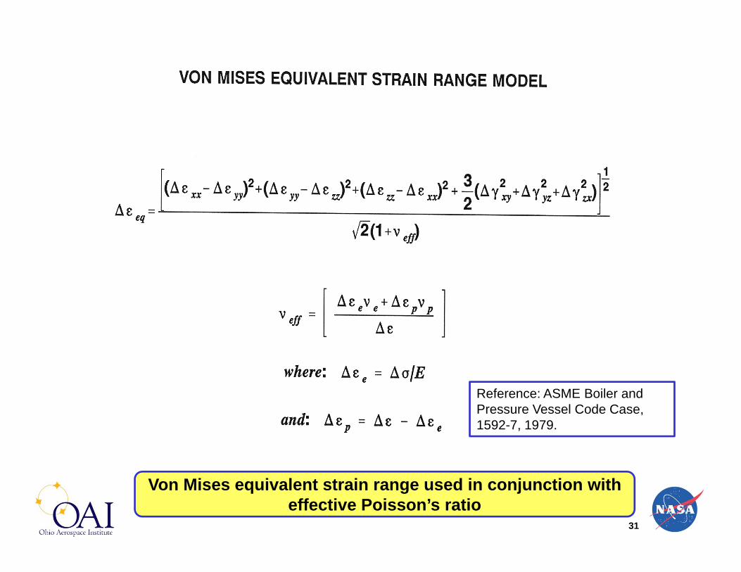
31
Von Mises equivalent strain range used in conjunction with effective Poisson’s ratio
Reference: ASME Boiler and Pressure Vessel Code Case, 1592-7, 1979.

32
Predictions of mechanically out-of-phase tests are higher (unconservative) due to additional hardening
Reference: Kalluri and Bonacuse, ASME PVP-Vol. 290, 1994, pp. 17-33

33
Uniaxial fatigue life relation and cyclic stress strain curve used with Von Mises equivalent strain range and MF
Reference: Bonacuse and Kalluri, Trans. of ASME, J. of Eng. Mat. and Tech., vol. 117, 1995, pp. 191-199.

34
Reference: Kalluri and Bonacuse, ASME PVP-Vol. 290, 1994, pp. 17-33
Predictions of mechanically out-of-phase tests are again higher (unconservative) due to additional hardening

35
Reference: Socie, Trans. of ASME, J. of Eng. Mat. and Tech., vol. 109, no. 4, 1987, pp. 293-298.
Modification of the original SWT parameter (1970) for multiaxial fatigue – materials with tensile mode of failure
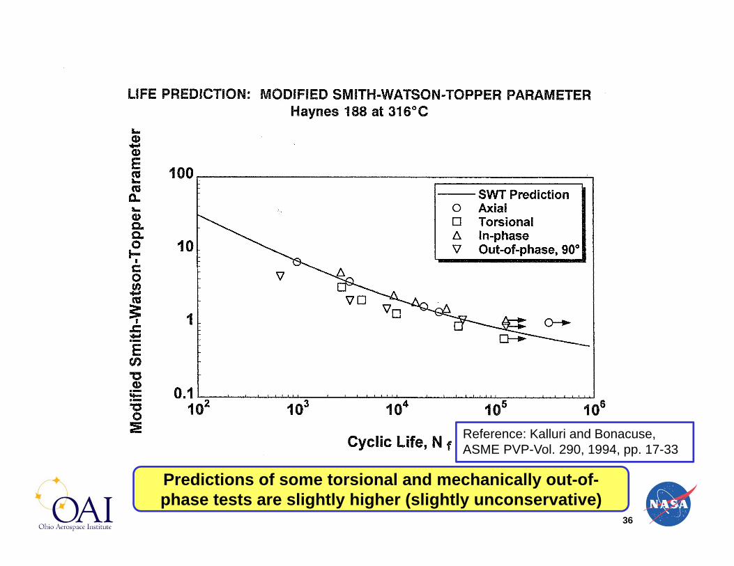
36
Reference: Kalluri and Bonacuse, ASME PVP-Vol. 290, 1994, pp. 17-33
Predictions of some torsional and mechanically out-of-phase tests are slightly higher (slightly unconservative)

37
References: Socie, 1987 and Fatemi & Socie, 1988
Max. shear strain on critical shear plane and max. normal stress on that plane – materials with shear mode of failure

38
Reference: Kalluri and Bonacuse, ASME PVP-Vol. 290, 1994, pp. 17-33
Predictions of mechanically out-of-phase tests are much higher (very unconservative)

39
Cyclic Hardening in Isothermal, Axial-Torsional, In- and Out-of-Phase Fatigue
Axial Shear
In out-of-phase tests, cyclic hardening increases with mechanical phase angle, between axial and shear strains
Reference: Bonacuse and Kalluri, ASTM STP 1184, 1994

40
Multiaxial and Thermomechanical Fatigue
Thermal Fatigue
SimultaneousLoads
Multiaxial
SequentialLoads
Multiaxial
Multiaxial TMF(Simultaneous & Sequential)
BithermalFatigue
ThermomechanicalFatigue
Non-IsothermalUniaxial
IsothermalMultiaxial
IsothermalUniaxial

41
Isothermal Axial and Torsional Cumulative Fatigue (Sequential Loading)
References:
[1] Miller, K. J., “Metal Fatigue—Past, Current, and Future,” Proc. Inst. Mech. Eng., Vol. 205, 1991, pp.1–14.[2] Weiss, J. and Pineau, A., “Continuous and Sequential Multiaxial Low-Cycle Fatigue Damage in 316Stainless Steel,” in Advances in Multiaxial Fatigue, ASTM STP 1191, D. L. McDowell and R. Ellis,Eds.,American Society for Testing and Materials, West Conshohocken, PA, 1993, pp. 183–203.[3] Harada, S. and Endo, T., “On the Validity of Miner’s Rule under Sequential Loading of RotatingBending and Cyclic Torsion,” in Fatigue Under Biaxial and Multiaxial Loading, ESIS10, K. Kussmaul,D. McDiarmid, and D. Socie, Eds., Mechanical Engineering Publications, London, 1991, pp.161–178.
• Historically, most investigations on cumulative fatigue limited to the same load-types (axial/axial, torsion/torsion, or rotating bending/rotating bending)
• Typical studies involve load order effects within a load-type (high/low or low/high)
• Dissimilar load-types can increase potential for interaction of damage (or mode of cracking)
• Evaluation of both load order and load-type sequencing effects is necessary

Time
High Amplitude (LCF Life, N1)
Low Amplitude (HCF Life, N2)
Applied Cycles, n1
Remaining Cycles, n2
42
Schematics of LCF/HCF and HCF/LCF Cumulative Fatigue Tests on Haynes 188 at 538°C
LCF/HCF HCF/LCF
Applied Life Fraction: n1/N1; Remaining Life Fraction: n2/N2
Time
Low Amplitude (HCF Life, N1)
High Amplitude (LCF Life, N2)
Applied Cycles, n1
Remaining Cycles, n2

43
• Linear Damage Rule [Palmgren, Langer, and Miner] (LDR):
• Nonlinear Damage Curve Approach [Manson and Halford] (DCA):
n1 and n2 are Applied Number of Cycles at Load Levels 1 & 2 andN1 and N2 are Fatigue Lives at Load Levels 1 & 2, respectively.
1
1
2
2
Nn1
Nn
4.0
2
1NN
1
1
2
2
Nn1
Nn
Cumulative Fatigue Life Prediction

44
Axial (High = 2.0%) / Axial (Low = 0.67%) InteractionHaynes 188 at 538°C
For all LCF/HCF data and HCF/LCF data for which n1/N1 > 0.4, DCA is Better than LDR
0.0 0.2 0.4 0.6 0.8 1.00.0
0.2
0.4
0.6
0.8
1.0
DCA LDRLCF, A / HCF, AHCF, A / LCF, ADCA
Life Fraction, n1/N1
NHCF, A = 39 255NLCF, A = 825
Life
Fra
ctio
n, n
2/N2
LCF/HCF
HCF/LCF
Orientation of Cracks( = 0° and 15°)
Orientation of Cracks( = 0°, 5°, 10°, and 15°)
Reference: Kalluri and Bonacuse, JAI, Vol. 7, No. 4, 2010

45
Axial (High = 2.0%) / Torsional (Low = 1.2%) InteractionHaynes 188 at 538°C
For all LCF/HCF data DCA is Better than LDR;However, for HCF/LCF data LDR is Better than DCA
0.0 0.2 0.4 0.6 0.8 1.00.0
0.2
0.4
0.6
0.8
1.0
DCA LDR LCF, A / HCF, T HCF, T / LCF, A DCA
Life Fraction, n1/N1
NHCF, T = 58 568
NLCF, A = 825
Life
Fra
ctio
n, n
2/N2
HCF/LCF
LCF/HCFOrientation of Cracks( = 0°, 15°, and 90°)
Orientation of Cracks( = 0°, 10°, and 15°)
Reference: Kalluri and Bonacuse, JAI, Vol. 7, No. 4, 2010
46
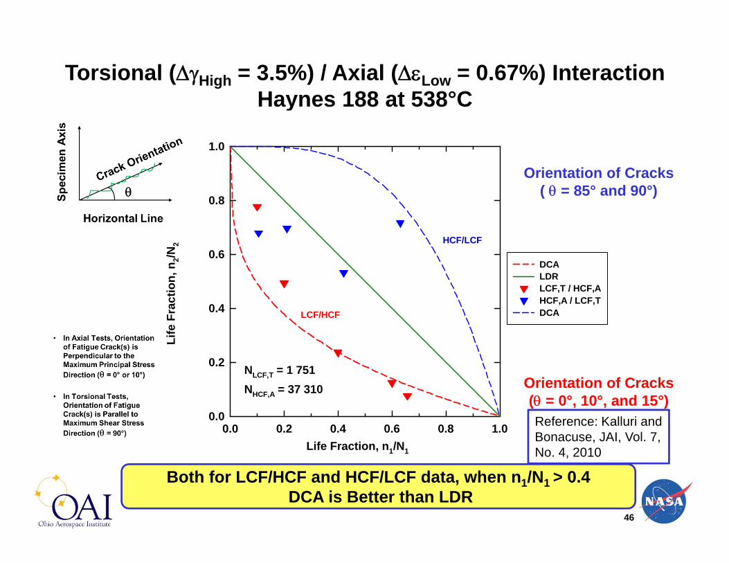
Torsional (High = 3.5%) / Axial (Low = 0.67%) InteractionHaynes 188 at 538°C
Both for LCF/HCF and HCF/LCF data, when n1/N1 > 0.4DCA is Better than LDR
0.0 0.2 0.4 0.6 0.8 1.00.0
0.2
0.4
0.6
0.8
1.0
DCA LDR LCF,T / HCF,AHCF,A / LCF,TDCA
Life Fraction, n1/N1
NHCF,A = 37 310NLCF,T = 1 751
Life
Fra
ctio
n, n
2/N2 HCF/LCF
LCF/HCF
Orientation of Cracks( = 0°, 10°, and 15°)
Orientation of Cracks( = 85° and 90°)
Reference: Kalluri and Bonacuse, JAI, Vol. 7, No. 4, 2010

47
Multiaxial and Thermomechanical Fatigue
Thermal Fatigue
SimultaneousLoads
Multiaxial
SequentialLoads
Multiaxial
Multiaxial TMF(Simultaneous & Sequential)
BithermalFatigue
ThermomechanicalFatigue
Non-IsothermalUniaxial
IsothermalMultiaxial
IsothermalUniaxial

48
Multiaxial, Thermomechanical Fatigue
• Torsional, TMF testing– Jordan, 1987 (4th Annual SEM Hostile Environments and High
Temperature Measurements Conference; Turbine blade superalloy(PWA 1480) tested between 425 to 828 °C)
– Bakis, Castelli, and Ellis, 1993 (ASTM STP 1191; Hastelloy-X tested between 400 to 600 °C, 600 to 800 °C, 800 to 1000 °C)
• Axial-Torsional TMF testing– Bonacuse and Kalluri, [1995 - AGARD Conference]; Kalluri and
Bonacuse, [1997, ASTM STP 1280] (Haynes 188 alloy tested between 316 and 760 °C)
– Meersmann, Ziebs et al. [1995 - AGARD Conference and 1996 – Kluwer Academic Publishers] (Inconel 738 LC and Single Crystal alloy SC16)
– Zamrik et al. [1996 – Kluwer Academic Publishers and 2000 – ASTM STP 1387] (Austenitic stainless steel tested between 399 and 621 °C)
– Brookes et al., 2010 (Materials Science and Engineering A; Near -TiAlalloy TNB-15 tested between 400 to 800 °C)

49
Mechanically In-Phase & Thermally In-Phase (MIPTIP)
0 150 300 450 600 750 900 1050 1200-0.01
-0.005
0
0.005
0.01A
xial
Str
ain
min
0 150 300 450 600 750 900 1050 1200-0.01
-0.005
0
0.005
0.01
Shea
r Str
ain
0 150 300 450 600 750 900 1050 1200Time [sec]
300
400
500
600
700
800
Tem
pera
ture
[°C
]max
max
min
Tmax
Tmin
Tmax = 760°CTmin = 316°C
C
D
B
A

50
Mechanically In-Phase & Thermally Out-of-Phase (MIPTOP)
0 150 300 450 600 750 900 1050 1200-0.01
-0.005
0
0.005
0.01A
xial
Str
ain
min
0 150 300 450 600 750 900 1050 1200-0.01
-0.005
0
0.005
0.01
Shea
r Str
ain
0 150 300 450 600 750 900 1050 1200Time [sec]
300
400
500
600
700
800
Tem
pera
ture
[°C
]max
max
min
Tmax
Tmin
Tmax = 760°CTmin = 316°C
A
B
C
D

51
Mechanically Out-of-Phase & Thermally In-Phase (MOPTIP)
0 150 300 450 600 750 900 1050 1200-0.01
-0.005
0
0.005
0.01
Axi
al S
trai
n
min
0 150 300 450 600 750 900 1050 1200-0.01
-0.005
0
0.005
0.01
Shea
r Str
ain
0 150 300 450 600 750 900 1050 1200Time [sec]
300
400
500
600
700
800
Tem
pera
ture
[°C
]max
max
min
Tmax
Tmin
Tmax = 760°CTmin = 316°C
A
B
C
D

52
Mechanically Out-of-Phase & Thermally Out-of-Phase (MOPTOP)
0 150 300 450 600 750 900 1050 1200-0.01
-0.005
0
0.005
0.01A
xial
Str
ain
min
0 150 300 450 600 750 900 1050 1200-0.01
-0.005
0
0.005
0.01
Shea
r Str
ain
0 150 300 450 600 750 900 1050 1200Time [sec]
300
400
500
600
700
800
Tem
pera
ture
[°C
]max
max
min
Tmax
Tmin
Tmax = 760°CTmin = 316°C
A
B
C
D
53
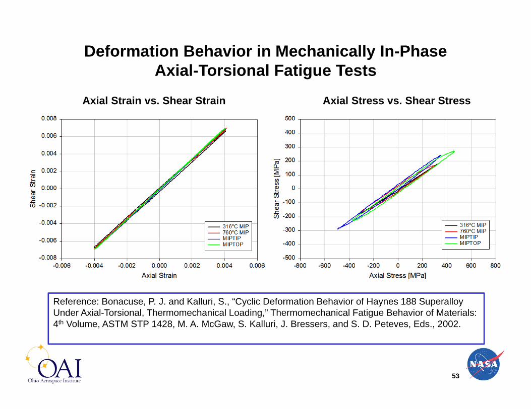
Deformation Behavior in Mechanically In-Phase Axial-Torsional Fatigue Tests
Axial Strain vs. Shear Strain Axial Stress vs. Shear Stress
Reference: Bonacuse, P. J. and Kalluri, S., “Cyclic Deformation Behavior of Haynes 188 SuperalloyUnder Axial-Torsional, Thermomechanical Loading,” Thermomechanical Fatigue Behavior of Materials: 4th Volume, ASTM STP 1428, M. A. McGaw, S. Kalluri, J. Bressers, and S. D. Peteves, Eds., 2002.
54
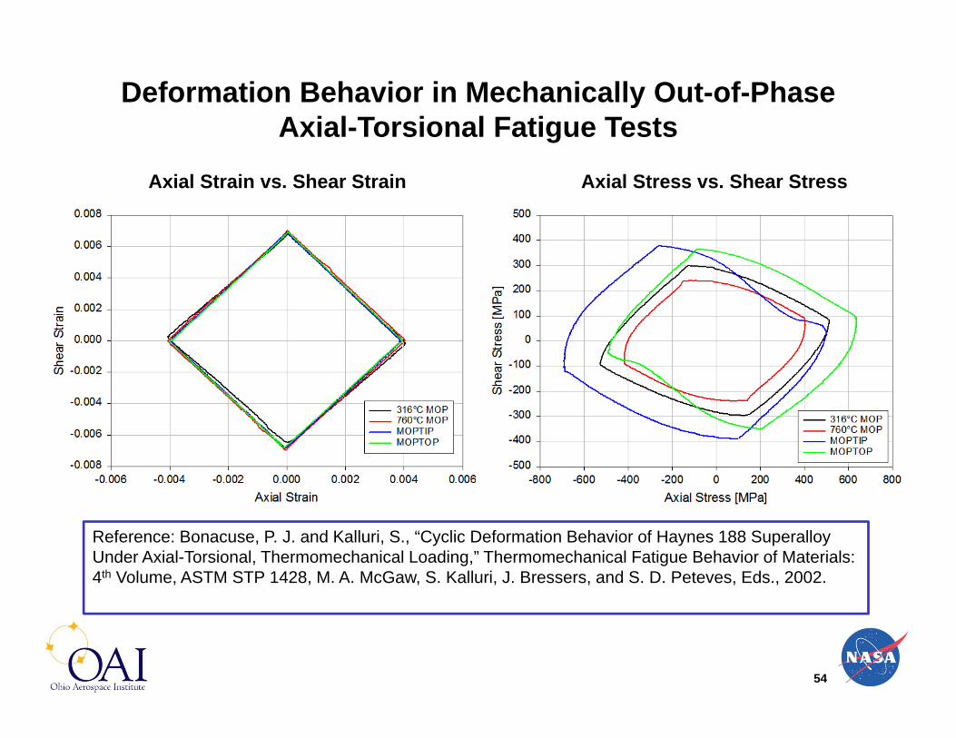
Deformation Behavior in Mechanically Out-of-Phase Axial-Torsional Fatigue Tests
Axial Strain vs. Shear Strain Axial Stress vs. Shear Stress
Reference: Bonacuse, P. J. and Kalluri, S., “Cyclic Deformation Behavior of Haynes 188 SuperalloyUnder Axial-Torsional, Thermomechanical Loading,” Thermomechanical Fatigue Behavior of Materials: 4th Volume, ASTM STP 1428, M. A. McGaw, S. Kalluri, J. Bressers, and S. D. Peteves, Eds., 2002.

55
Evolution of Maximum and Minimum Stresses in Mechanically Out-of-Phase Axial-Torsional Fatigue Tests
Axial Stress Shear Stress
Reference: Bonacuse, P. J. and Kalluri, S., “Cyclic Deformation Behavior of Haynes 188 SuperalloyUnder Axial-Torsional, Thermomechanical Loading,” Thermomechanical Fatigue Behavior of Materials: 4th Volume, ASTM STP 1428, M. A. McGaw, S. Kalluri, J. Bressers, and S. D. Peteves, Eds., 2002.

56
Additional Hardening in Axial-Torsional Fatigue Tests
Axial-Torsional TMF loading causes more hardening than Axial-Torsional isothermal loading
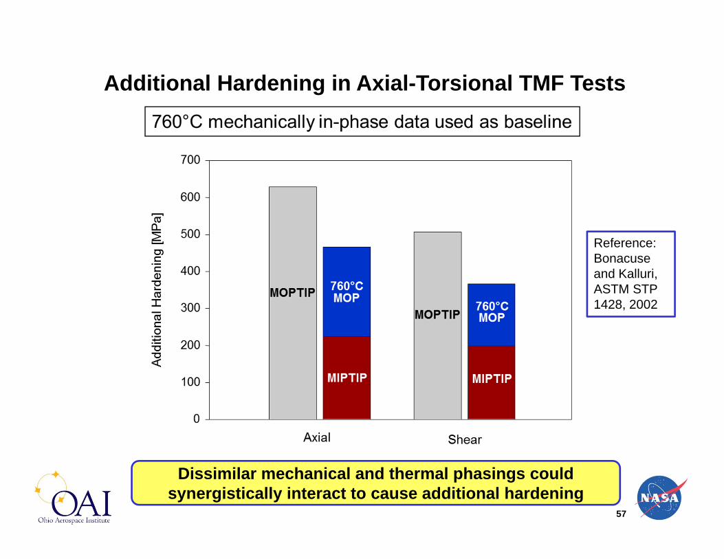
57
Additional Hardening in Axial-Torsional TMF Tests
Dissimilar mechanical and thermal phasings could synergistically interact to cause additional hardening
Reference: Bonacuse and Kalluri, ASTM STP 1428, 2002

58
Axial-Torsional TMF Tests: Haynes 188 (316 to 760 °C)
Thermally in-phase tests yielded lower cyclic lives regardless of the mechanical phasing
Reference: Kalluri and Bonacuse, ASTM STP 1280, 1997

59
Multiaxial, Thermomechanical Fatigue --Some Future Challenges
• Cumulative fatigue under multiaxial, thermomechanicalloads
• TMF under biaxial and equi-biaxial ( = 1) loading conditions
• Determination of material’s TMF behavior with specimens versus testing subcomponents of structures
• Influence of coatings on structural alloys• Roles of residual stresses and environment• Composites and functionally graded materials

60
Cumulative Fatigue Example : Uniaxial TMF and Isothermal Fatigue
Source: Halford et al., 1983
Cumulative fatigue behavior with out-of-phase TMF LCF and Isothermal HCF under uniaxial loading conditions
Reference: McGaw, M. A., ASTM STP 1186, 1993, pp. 144-156.

61
Multiaxial, Thermomechanical Fatigue -- Future Challenges
• Thermomechanical fatigue under biaxial and equi-biaxial ( = 1) loading conditions (thin-walled tubular specimens with internal/external pressure or cruiciform specimens)
– TMF system for testing cruciform specimens (Scholz, Samir, and Berger, Proc. of 7th Int. Conf. on Biaxial and Multiaxial Fatigue & Fracture, Elsevier, 2004)
• Determination of material’s TMF behavior with specimens versus testing subcomponents of structures (scale-up issues and reproducing service conditions)
– Test conditions are well defined and controlled for a chosen specimen design
– Tests involving subcomponents are more complex due to the difficulties involved in attaining required temperature profiles and imposing necessary multiaxial loads (design typically accomplished with analysis supplemented with limited testing for validation)

62
Multiaxial, Thermomechanical Fatigue -- Future Challenges
• Influence of coatings (for example, thermal and environmental barrier coatings) on the multiaxial, TMF life of components
– LCF and HCF behavior of thick thermal barrier coatings investigated with a high power CO2 laser (Zhu and Miller, NASA TM-1998-206633)
– Thermal barrier coating / superalloy system tested multiaxial TMF (Bartsch et al., Int. J. of Fatigue, 2008); Thermal gradient mechanical fatigue tests on coated tubular specimens of IN 100 DS superalloy
• Roles of residual stresses and environment on the fatigue crack initiation under multiaxial, thermomechanical loads
– Depending upon the maximum temperature in the TMF cycle, any existing residual stresses may relax completely. However, at low maximum temperatures and small inelastic strains, residual stresses could influence fatigue life
– Oxidation plays a significant role and interacts with other damage mechanisms activated by multiaxial loads during TMF. Inert and vacuum environments could exhibit different damage modes under mutliaxial TMF.

63
Acknowledgements
• Mechanical testing, analysis of results, and technical discussions
– Mr. Peter J. Bonacuse, Dr. Bradley A. Lerch, Mr. Christopher S. Burke, Dr. Michael A. McGaw, and Mr. Michael G. Castelli
• Steadfast Support and Encouragement– Dr. Steven M. Arnold, Ms. Ann O. Heyward, Dr. Michael L. Heil,
Mr. John R. Ellis (retired), and Late Mr. Marvin H. Hirschberg• Mentorship
– Late Prof. S. S. Manson and Late Dr. Gary R. Halford• Financial support provided by NASA Glenn Research
Center Contract to USRA (NNC13TA85T; Task Number NNC13TA85T) and USRA Subcontract to OAI under Subtask NNC13TA85T-08

64
Mutiaxial Thermomechanical Fatigue (MTMF)
Multiaxial Thermomechanical Fatigue (MTMF) can Induce Additional Cyclic Hardening and can Lower
Fatigue Life Significantly Compared to Uniaxial Thermomechanical Fatigue and Isothermal
Multiaxial Fatigue!
MTMF should be Properly Evaluated in Designing and Lifing Engineering Components!!


![Effect of Constitutive Model on Thermomechanical Fatigue ... · subjected automotive powertrain components to severe thermomechanical fatigue (TMF) loadings [1]. The design against](https://img.dokumen.tips/doc/110x75/5e932c9e8a6031207607f5b6/effect-of-constitutive-model-on-thermomechanical-fatigue-subjected-automotive.jpg)