Embed Size (px)
Citation preview

Multi-Tasking Turning Center

02
The integration of machining center and turning center gives you unmatched flexibility
in a wide variety of part configurations. From simple turning and milling, to complex
multi-axis simultaneous machining, all operations can be completed in one machine.
Off-center machining with the Y-axis and milling of angled surfaces with
the B-axis greatly increases the range of machine applications.

03
Multi-Tasking Turning Center

04
Left Spindle
C1-axis
Lower Turret
X2-axis A-axis
C2-axis
B-axis
Z1-axis
60°
X1-axis
Milling Spindle
Y-axis Right Spindle
Z2-axis
Machine Construction
PUMA MX series
The milling spindle(s) and the lower turret can be coordinated to enable machining at the left or right spindle.
Robust Design
Guideway span
MX2100
X1-axis 285 / 315 mm (11.2 / 12.4 inch)
Z1-axis 540 / 473 mm (21.3 / 18.6 inch)
Y-axis 435 mm (17.1 inch)
The heavily ribbed torque tube design prevents twisting and deformation. All guideways are wide wrap-around rectangular type for unsurpassed long-term rigidity and accuracy.
Stable base for supporting multi-machining
PUMA MX2100
PUMA MX1600
Multi-process capabilityShorter setup timesOptimal cycle distributionAutomated operation support
PUMA MX -maximum economy and
productivity
Rapid traverse
X1-axis 36 m/min (1417.3 ipm)
Z1-axis 36 m/min (1417.3 ipm)
Y-axis 26 m/min (1023.6 ipm)
All carriages are mounted on roller-type, linear motion guides to provide high accuracy and rigidity while reducing non-cutting time.- Zero clearance from preload High permissible load- Low friction & wear (LM μ = 0.002~0.003)- Simple maintenance over the long haul
Linear Motion Guide (Roller type)
LMG (Roller type)
Finite Element Method (FEM) analysis results in superior machine stability.
FEM
1
6
8
7
2
3
5
4
PUMA MX1600
PUMA MX1600S
PUMA MX1600T
PUMA MX1600ST
1 Left spindle (Mill-turn) : 175mm (6”) chuck
● ● ● ●
2 Right spindle (Mill-turn) : 175mm (6”) chuck
× ● × ●
3 Tail stock : Servo driven type ● × ● ×
4 Lower turret : 16-station 6000 r/min rotary tool
× × ● ●
5 Roller guide ways for all axes ● ● ● ●
6 Milling spindle : 12000 r/min, Capto C5
● ● ● ●
7 B-axis : Roller gear cam ● ● ● ●
8 ATC & Magazine : 40 ea, Servo driven
● ● ● ●

05
Thermal compensation systemMilling spindle thermal growth can be compensated for spindle axis direction only. Effectively removes positional deviation of spindle nose due to changing rotational speed.
Milling spindle headbody (PT1), bed (PT2)
Axis Features
(40.2 / 59.1)
1020 / 1500
(40.2 / 59.1)
1020 / 1500
ø660
/ ø7
60(ø
26.0
/ 29
.9)
ø540
/ ø6
70(ø
21.3
/ 26
.4)
170 / 230(6.7 / 9.1)
60°
PUMA MX 2100/2100L
PUMA MX2600/3100
MX1600
X1-axis 565 (22.2) 630 (24.8) 450 (332.1)
X2-axis 187 (7.4) 220 (8.7) 165 (121.8)
Z1-axis 1050/1550(41.3 / 61.0) 1585 (62.4) 935 (690.0)
Z2-axis 1050/1550(41.3 / 61.0) 1515 (59.7) 925 (682.7)
Axis travel Unit : mm (inch) Rapid travel Unit : m/min (ipm)Max. working diameter, length (MX 2100 / MX 2600, 3100)
PT2
PT1
Precise indexing control of B-axis makes milling jobs on inclined plane possible.
The angular position of the B-axis is controlled using precision ground roller gear cam and a highly accurate servo motor.
A rigid, double-slide Y-axis construction withstands cutting forces generated during heavy-duty turning and milling.
B-axis rotating range
Precision control B-axis movement
B-Axis with Virtual Y-Axis Virtual Y-axis function
High rigid roller gear cam
B-axis rotation range ± 120°B-axis indexing time 2 s (90°)
Y-axis stroke 170 mm (6.7 inch) / 230 mm (9.1 inch) [±85 mm (3.4 inch) / ±115 mm (4.5 inch)]
Y-axis rapid traverse 26 m/min (1023.6 ipm)
• 5° indexing (by coupling clamp)• Contouring control in 0.001° increment
Position of temperature sensors
PUMA MX2100ST
PUMA MX2600ST
MX1600
X1-axis 36 (1417.3) 36 (1417.3) 36 (1417.3)
X2-axis 24 (944.9) 24 (944.9) 24 (944.9)
Z1-axis 36 (1417.3) 36 (1417.3) 36 (1417.3)
Z2-axis 36 (1417.3) 36 (1417.3) 36 (1417.3)
A-axis 30 (1181.1) 30 (1181.1)
C-axis 400 (15748.0) r/min 400 (15748.0) r/min

06
PUMA MX series
Perfect C-axis control of both spindles
C1, C2-axis index 360° [in 0.001° increment]
Both spindles, left and right, are engineered to minimize the loss of precision through thermal distortion, and to ensure superior performance in applications ranging from heavy-duty cutting at high power and low speed, to fine finishing at high speed.
Max. spindle speed Motor (30 min)
PUMA MX1600 6000 r/min 15 kW (20.1 Hp)
PUMA MX2100 5000 r/min 22 kW (29.5 Hp)
PUMA MX2600 4000 r/min 26 kW (34.9 Hp)
PUMA MX3100 3000 r/min 30 kW (40.2 Hp)
Right Spindle *1
Right Spindle
*1 : on only S/ST type machine
C&Z-axis cylindrical interpolation C&X-axis polar interpolation
R
CC-axis
Z-axis
C1, C2-axis contouring torque
MX1600 208 N·m (153.5 ft·lb)
MX2100S [L/ST/LST] 318 N·m (125.5 ft·lb)
MX2600S/ST 700 N·m (516.6 ft·lb)
MX3100S 1203 N·m (887.8 ft·lb)
Main SpindleThe Perfect Design for Built-in Motor-Driven Spindles.
Main Spindle
C-axisZ-axis

07
Spindle power-torque diagram
Cooling oil
Cooling fin
Both the left and right spindles employ an integral cooling system that circulates coolants through the entire spindle structure. This eliminates thermal distortion in all applications from heavy-duty cutting at high power and low speeds to fine and finish cutting at high speed.
Oil cooling unit for left & right spindles
PUMA MX 2100 series (Left & right spindle)• Spindle motor power : 22 kW (29.5 Hp)• Max. Spindle speed : 5000 r/min
PUMA MX 2600 series (Left & right spindle)• Spindle motor power : 26 kW (34.9 Hp)• Max. Spindle speed : 4000 r/min
PUMA MX 3100 series (Left spindle)• Spindle motor power : 30 kW (40.2 Hp)• Max. Spindle speed : 3000 r/min
PUMA MX 3100 series (Right spindle)• Spindle motor power : 26 kW (34.9 Hp)• Max. Spindle speed : 4000 r/min
PUMA MX1600
Out
put :
kW
(Hp)
Spindle Speed (r/min)30 100 400
175 N·m (129.2 ft·lb)S1 Cont.
318 N·m (234.7 ft·lb)S3 15%
239 N·m (176.4 ft·lb)S3 25%
161 N·m (118.8 ft·lb)S2 30min
135 N·m (99.6 ft·lb)S1 Cont.
S3 15% 15kW (20.1Hp) S3 25%
22kW (29.5Hp) S2 30min18.5kW (24.8Hp) S1 Cont.
11kW (14.8Hp) S1 Cont.
450600 1300 5000
750 1500 60001 (1.3)
5 (56.7)
10 (13.4)
25 (33.5)20 (26.8)
15 (20.1)
Out
put :
kW
(Hp)
Spindle Speed (r/min)
S3 25%
398 N·m (293.7 ft·lb)539 N·m (397.8 ft·lb)
262 N·m (193.3 ft·lb)310 N·m (228.8 ft·lb)
700 N·m (516.6 ft·lb)
26kW (34.9Hp) S2 30min22kW (29.5Hp)S2 30min 22kW (29.5Hp) S1
15kW (20.1Hp) S1
300
360
390
800 1000 2000 3000 40000
10 (13.4)
30 (40.2)
20 (26.8)
Out
put :
kW
(Hp)
Spindle Speed (r/min)
1203 N·m (887.8 ft·lb)1003 N·m (740.2 ft·lb)
572 N·m (422.1 ft·lb)477 N·m (352.0 ft·lb)
S2 10min 30kW (40.2Hp) S2 30min
25kW (33.5Hp) S1
16.7 (22.4)
21 (28.2)
1000
1600500238
2000 30000
10 (13.4)
20 (26.8)
30 (40.2)
40 (53.6)
Out
put :
kW
(Hp)
Spindle Speed (r/min)
398 N·m (293.7 ft·lb)539 N·m (397.8 ft·lb)700 N·m (516.6 ft·lb)
310 N·m (228.8 ft·lb)202 N·m (149.1 ft·lb)
S3 25%
22kW (29.5Hp) S2 30min
26kW (34.9Hp) S2 30min
15kW (20.1Hp) S1
22kW (29.5Hp) S1
800300
360390
1000 4000300020000
10 (13.4)
20 (26.8)
30 (40.2)
1 (1.3)
10 (13.4)
10 (7.4)
100 (73.8)
10 100 1000
300 (221.4) 30 (40.2)
6000
Low T=208 N·m (153.5 ft·lb) S3 40%Low T=157 N·m (115.9 ft·lb)S2 30min
Low T=140 N·m (103.3 ft·lb) S1 Cont.
High T=75 N·m (55.4 ft·lb) S1 Cont.
High T=102 N·m (75.3 ft·lb) S2 30min
11kW (14.8 Hp) S1 Cont.15 kW (20.1 Hp) S2 30min
15 kW (20.1 Hp) S2 30min15 kW (20.1 Hp) S3 40%
688750
910
1400
Spindle Speed (r/min)
Torque : N·m (ft·lb) Power : kW (Hp)

08
Milling spindle power-torque diagram
The 360° angular positioning of the milling spindle can accommodate multi insert turning tools that are equipped with two, three, or four inserts.
Dual Contact Tools (MX 1600 - CAPTO C5, MX2100/2600/3100 - CAPTO C6)
Max. spindle speed 12000 r/min
Motor Torque
PUMA MX1600 9 kW (12.1 Hp) [10 min] 49 N·m (36.2 ft·lb)
PUMA MX2100 18.5 kW (24.8 Hp) [10 min] 81 N·m (59.3 ft·lb)
PUMA MX2600/3100 22 kW (29.5 Hp) [15 min] 118 N·m (87.1 ft·lb)
PUMA MX2100 series• Spindle motor power : 18.5 kW (24.8 Hp)• Max. Spindle speed : 12000 r/min
PUMA MX2600/3100 series• Spindle motor power : 22 kW (29.5 Hp)• Max. Spindle speed : 12000 r/min
PUMA MX1600
PUMA MX series
Milling SpindleTurning and Milling Perfectly Integrated.
Oil-based coolants circulate through the milling spindle, allowing perfect integration of turning and milling applications. An air-gap sensor confirms the clamping status of both tools and parts.
Milling Spindle
Out
put :
kW
(Hp)
Spindle Speed (r/min)100 500 1000 2000
1300 2300 6000
5000 120001 (1.3)
5 (56.7)
25 (33.5)20 (26.8)15 (20.1)
10 (13.4)81 N·m (59.8 ft·lb)
29 N·m (21.4 ft·lb) S2 10min24 N·m (17.7 ft·lb) S2 30min
18 N·m (13.3 ft·lb) S1 Cont.
S3 10%
S3 10%
60 N·m (44.3 ft·lb)S3 15%
S3 15%1750
46 N·m (33.9 ft·lb)S3 25%
31 N·m (22.9 ft·lb)S1 Cont.
11kW (14.8Hp) S3 25%
75kW (10.1Hp) S1 Cont.
18.5kW (24.8Hp) S2 10min15kW (20.1Hp) S2 30min
11kW (14.8Hp) S1 Cont.
Out
put :
kW
Spindle Speed (r/min)100 500 1000 2000 6000
1500 4500 10000
120001 (1.3)
5 (56.7)
25 (33.5)20 (26.8)15 (20.1)
10 (13.4)
14 N·m (10.3 ft·lb) S1 Cont.18 N·m (13.3 ft·lb) S2 30min
21 N·m (15.5 ft·lb) S2 15min
118 N·m (87.1 ft·lb)S3 15%
64 N·m (47.2 ft·lb)S1 40%
95 N·m (70.1 ft·lb)S3 40%
18.5kW (24.8Hp) S3 15%15kW (20.1Hp) S3 40%
10kW (13.4Hp) S1 Cont.
22kW (29.5Hp) S2 15%18.5kW (24.8Hp) S2 40%15kW (20.1Hp) S1 Cont.
100 10001450 2500 5000 12000
100 (73.8)
Spindle Speed (r/min)
Torque : N·m (ft·lb) Power : kW (Hp)
1 (0.13)
1 (1.3)
10 (13.4)
1 (0.7)
10 (7.4)
Low T=20 N·m (14.8 ft·lb) Cont.
High T=19.1 N·m (14.1 ft·lb) Cont.
7.5 kW (10.1 Hp) S3 10%7.5 kW (10.1 Hp) S3 25%
9.0 kW (12.1 Hp) S3 15%
Low T=28.6 N·m (21.1 ft·lb) S3 25%
Low T=49.4 N·m (36.5 ft·lb) S3 10%
High T=14.3 N·m (10.6 ft·lb) S3 40%
1770 4500 10000
Low T=21 N·m (15.5 ft·lb) S3 40%
3.7 kW (4.7 Hp) S1 Cont.
High T=7.07 N·m (5.2 ft·lb) 15%
7.5 kW S3 40%5.5 kW (7.4 Hp) S3 40%(10.1 Hp)

09
Tool Magazine with ATC
40 ea / 80 ea
The ATC consists of a servo-driven tool magazineand change arm.
Tool storage capacity
Advanced mechanisms significantlyreduce non-cutting time.
Automatic Tool Changer (ATC)
Tool Magazine
Maximum tool size
Tool change time
PUMA MX1600 2.1 s (T - T - T)
PUMA MX2100 2.0 s (T - T - T)
PUMA MX2600/3100 2.0 s (T - T - T)
Max. tool length [L]Max. tool diameter [A]
Max. tool weight [W] Max. moment[W x L1]Adjacent pots are empty Continuous
PUMA MX1600 200 mm (7.9 inch) Ø 95 mm (3.7 inch) Ø 70 mm (2.8 inch) 4 kg (8.8 lb) 3.9 N·m (2.9 ft·lb)
PUMA MX2100 300 mm (11.8 inch) Ø 120 mm (4.7 inch) Ø 90 mm (3.5 inch) 8 kg (17.6 lb) 7.54 N·m (5.6 ft·lb)
PUMA MX2600/3100 400 mm (15.8 inch) Ø 130 mm (5.1 inch) Ø 90 mm (3.5 inch) 10 kg (22.0 lb) 9.81 N·m (7.2 ft·lb)

10
The 12-station, heavy-duty lower turret features a large-diameter Curvic coupling with heavyduty design for maximum rigidity under tough cutting conditions. Turret rotation, acceleration and deceleration are controlled by a high-torque servo motor. Unclamp and rotation are virtually simultaneous. The fast index response keeps cycle times short.
Lower Turret *1
The turret accommodates BMT55P and BMT65P toolingin which the toolholders are mounted directly to theturret’s periphery with 4 large bolts. This type of mounting system generates exceptionally high rigidity.
Radial BMT45P (MX1600), BMT55P (MX2100) and the BMT65P (MX2600)
Index time (1-station swivel) 0.2 sNo. of tool station 12 ea (MX2100/2600/3100)
16 ea (MX1600)*1 : on only T, ST type machine
BMT45P (MX1600)BMT55P (MX2100)BMT65P (MX2600)
PUMA MX series
Lower TurretDesigned for High Accuracy
Rotary tool spindle power-torque diagramPUMA MX2100 series• Spindle motor power : 5.5 kW (7.4 Hp)• Max. Spindle speed : 5000 r/min
PUMA MX2600 series• Spindle motor power : 7.8 kW (10.5 Hp)• Max. Spindle speed : 4000 r/min
PUMA MX1600
Out
put :
kW
(Hp)
Spindle Speed (r/min)
20 100 250 500 1000 2000 3500 50000.1 (0.1)
1 (1.3)
2 (2.7)
4 (5.4)
10 (13.4)
6 (8)
750 1115 2500 4000
47 N·m (3
4.7 ft·lb)
14 N·m (1
0.3 ft·lb)
5.5kW (7.4Hp) S3 25%
1.1kW (1.5Hp) S1
Out
put :
kW
(Hp)
Torq
ue :
N·m
(ft·l
b)
Rotary Tool Spindle Speed (min-1)1000 2000 3000 4000
10 (7.4) 70 (93.9)
60 (80.5)
50 (67.1)
40 (53.6)
30 (40.2)
25 (33.5)
20 (26.8)
15 (20.1)
10 (13.4)
5 (6.7)
9 (6.6)
8 (5.9)
7 (5.2)
6 (4.4)
5 (3.7)
4 (3)
3 (2.2)
2 (1.5)
1 (0.7)
0
7.7kW (10.3Hp) 5min rating
6.8kW (9.1Hp) 10min rating
7.8kW (10.5Hp) 30min
4.5kW (6.0Hp) Cont.
T=24.3 N·m (17.9 ft·lb) 5min rating T=21.6 N·m (15.9 ft·lb) 10min rating T=18.5 N·m (13.7 ft·lb) 30min rating T=14.3 N·m (10.6 ft·lb) Cont.
Spindle Speed (r/min)
Torque : N·m (ft·lb) Power : kW (Hp)
1 (0.7)
5 (3.7)
10 (7.4)
50 (36.9)
100 10000.1 (0.13)
1 (1.3)
6000
5 (6.7)
1500 2230 5000
5.5 kW (7.4 Hp) S3 25%
1.1 kW (1.5 Hp) S1 Cont.
T=23.5 N·m (17.3 ft·lb) S3 25%
T=7 N·m (5.2 ft·lb) S1 Cont.

11
The tail stock is driven by an AC servo motor and ball screw. Tail stocks thrust force can be controlled and adjusted by using the controls M-code function.
Servo Driven Tail Stock *1
Machining Capacity
*1 : The servo-driven tail stock with dead center (built in center) is standard on MX2100, 2600/3100 models, but not on those designated as S and ST models.
Model Unit MX1600 MX2100 MX2600 / 3100
Bore taper MT#4 MT#4 MT#5
Travel mm (inch) 935 (36.8) 1050 (41.3) 1550 (61.0)
Max.thrust force
N (lbs)
3500(786.8)
7000 (1573.6)
10000 (22480.0)
Programmable tail stock specifications
Spindle speedr/min
Cutting speedm/min (ipm)
Feedratem/rev
Cutting depthmm (inch)
Material removal ratecm3/min (in3/min)
910 200 (7874) 0.4 10 (0.4) 800 (315.0)
Heavy duty cutting (MX2600) (OD)
Milling Spindle speedr/min
Tool [6Z]mm (inch)
Cutting depthmm (inch)
Feedratem/rev
Material removal ratecm3/min (in3/min)
1100 Ø80 (3.2) 5 (0.2) 1.0 330 (129.9)
Milling 1 (MX2600) (Face milling)
Milling Spindle speedr/min
Tool [6Z]mm (inch)
Cutting depthmm (inch)
Feedratem/rev
Material removal ratecm3/min (in3/min)
380 Ø25 (1.0) 25 (1.0) 0.5 119 (46.9)
Milling 2 (MX2600) (End milling)
Milling Spindle speedr/min
Tool [U-drill]mm (inch)
Feedratem/rev
Material removal ratecm3/min (in3/min)
2000 Ø40 (3.2) [6Z] 0.2 503 (9.7)
Milling 3 (MX2100) (Drilling)
• Workpiece material, KS (JIS) : SM45C (S45C), Carbon steel• The cutting test results indicated above are obtained as an example through real test cutting.• The results may not be obtained due to differences in cutting and environmental conditions during measurement.

12
Application of Hybrid Motor Starter (Standard Specifications)Innovative maintenance-free conditions have been realized compared with conventional motor-driven starters via the application of a hybrid motor starter that allows intellectual switching and simple cabling upon frequent operation of the coolant pump motor.
The hybrid motor starter is capable of starting up the motor faster and more securely than competing motor starters.
Hybrid switching technology, fitted with semiconductors for the supply of power, allows streamlined switching, thereby radically reducing the load on relay contacts and extending the lifecycle of the motor starter tenfold compared with conventional switch gear, and facilitates simple and efficient cabling design at the control and signal levels.
Hybrid motor starter that allows intellectual motor switching and simple cabling
Alarm Guidance
Machine - Airbag Function
Periodic maintenance function
Easy Operation System
Easy Alarm Check-up & Troubleshooting
User check-up points notice function
Self check-up function (OK / NG)
Status of actuators & sensors of unit
• It is available on the servo axis (X, Z, B, Y-AXIS).• This function can not prevent collision but can minimize collision damege.
The principle of Machine-airbag Function1. Higher torque load can be detected than setting vale if machine come into collision.2. Servo Unit automatically move in the reverse direction instaneously.
Detect the torque data
Protect the machine unit
Machine collision
Minimizethe damage
Instaneous reversedirection moving
• Avoid Unexpected Downtime• Optimize the performance• Increase Efficiently• Reduce operating costs
Extends the Life of the Tool Machine
Machine collision, defection or cutter damage
DAMAGE to the machine Minimize the DAMAGE
Machine-airbag function
Caused large load torque

13
Various Optional Equipments
Combined MX technology with Swiss-turn function for biomedical complex shapes
• Bar feeder• Parts unloader &
Parts conveyor• Work ejector
Thermal displacement and dimensional accuracy aregreatly influenced by oil temperature in a machine.Coolant Temperature Control unit prevents the coolantfrom heating. Especially, when using oil-based coolant,the oil temperature can become extremely high.
Guide bush*
Optional Equipmentsfor Automation
Coolant chiller
Oil mist collector Oil skimmer
Tool setter
Servo driven steady rest (Automatic type)
Tool magazine 80 tools
MQL (Minimum quantity lubrication)
Air+Oil mist Misting device
Rotary guide bush Below 21 mm (0.8 inch)
Fixed guide bush Below 22 mm ~ 42 mm (0.9 inch ~ 1.7 inch)
RotarRotary guide bush
Fixed guide bush
Bar ø21 mm
Bar ø42 mm
(0.8 inch)
(1.7 inch)
* : PUMA MX1600T / ST
Coolant Chiller
Coolant Tank

14
PUMA MX1600Unit : mm (inch)
TURNING TOOL
ID HOLDER
ROTARY TOOL
PLUG
GUIDE BUSH
OD, FACE, CUT-OFF
16ST TURRET
BMT 45P
OD Tool Holder
Straight Milling Unit For Face Cutting
Angular Milling Unit For Face Cutting
Dummy Plug
Fixed Guide Bush
Rotary Guide Bush
Double OD Tool Holder
Face Tool Holder
Cut-off Tool Holder
ID Tool Holder
OD Tool(ER20)
Cut-off Holder (ER20)
Boring Bar SleevesØ10-H32Ø12-H32Ø15-H32Ø20-H32Ø25-H32
Boring Bar
U-Drill (Ø25)
Drill
U-drill SleevesØ20-H32Ø25-H32
Drill SocketMT NO.1MT NO.2MT NO.3
Holder Coverfor U-Drill
Collet Chuck
Milling Adapter
Weldon Adapter(ID16)
COLLET[ER20]Ø2-Ø13
Tooling System

15
PUMA MX2100, PUMA MX2600
12st Turret
TURNING TOOL
ID HOLDER
ROTARY TOOL
PLUG
OD, FACE, CUT-OFF OD Tool Holder
OD Tool[□25(1)]
Cutting Tool[□25(1)]
Boring Bar SleevesØ10-H40 (Ø3/8-H14/7)Ø16-H40 (Ø1/2-H14/7)Ø25-H40 (Ø5/8-H14/7)Ø12-H40 (Ø3/4-H14/7)Ø20-H40 (Ø1-H14/7)Ø32-H40 (Ø11/4-14/7)
Boring Bar
U-Drill
Drill
U-drill SleevesØ20-H40 (Ø3/4-H14/7)Ø25-H40 (Ø1-H14/7)Ø32-H40 (Ø11/4-H14/7)
Drill SocketMT NO.1MT NO.2MT NO.3
Straight Milling Head For Side Cutting
Holder Coverfor U-Drill
Collet Adapter
Milling Arbor Adaptor
Weldon Adapter(ID16)(ID20)
COLLET[ER25]Ø3-Ø16(Ø1/8-3/4)
[ER32]Ø3-Ø20(Ø1/8-3/4)
Angular Milling Head For Face Cutting
Dummy Plug
Double OD Tool Holder
Face Tool Holder
Cut-off Tool Holder
ID Tool Holder
BMT 55PBMT 65P
• PUMA MX 2100• PUMA MX 2600
Unit : mm (inch)
Note) Above tooling system is our recommendation. Depending on export condition, the standard tooling packed with the machine can be different.

16
Milling spindle
The adapters, in longand short version,make it possible toextend the total length.
Rotating Tools
Turning Tools
CoroMill milling cutters withCoromant Capto coupling
CoroMill milling cutters and adapters
Indexable insert drills with Coromant Capto coupling
Indexable insert drills and adapters
Boring tools with Coromant Capto coupling
45° Coromant Capto cutting units for turning
90° Coromant Capto cutting units for turning,threading parting and grooving
Standard shank tools and adapters for turning, threading parting
and grooving
Coromant Capto cutting units for turning,threading
Boring bars and adapters
Three tools in one:one position in the magazine containning
three standard shank tools.
Modular tooling system570-cutting heads for turning, threading,parting and grooving and boring bars in
different designs
Special tools andengineered products
Multi-function type, suitable for both rotary and fixed tool cutting in milling and lathe
Blanks to be shapedaccording to your needs
CoroMill modular cutting heads and a variety of
shanks
Endmills, shart hole drills and taps with a large
number of adapter
MX1600: CAPTO C5MX2100/2600/3100: CAPTO C6
Unit : mm (inch)
Tooling System
• All holders are not supplied. It is only reference for you.

17
122(4.8)
935 (36.8)(Z1-Stroke) 130(5.1)465.5 (18.3)(Z1-Ref. Point)
10 (0.4
)
225.
5 (8
.9)
400
(15.
7)
636.5 (25.1) 407 (16.0) 39(1.5)
35(1.4)
60 (2.4
)
60(2.4)
35 (1
.4)
104.5(4.1)
935 (36.8) (A-Stroke)
1187 (46.7)
174.
5 (6
.9)
147.5 (5.8)
85(3
.3)8
5(3.
3)17
0 (6
.7)(
Y-St
roke
)
25 (1.0
)
275.
5 (1
0.8)50
(2.0)150(5.9)
30(1.2)
40(1.6)
209.
5(8
.2)
40 (1.6
) 25 (1.0
)45 (1.8
)130.
5(5
.1)
125(4.9)
20(0.8)
520(20.5)
50 (2
.0)
55(2
.2)3
0(1.
2)
122(4.8)
229
(9.0
)10
5(4.
1)11
6(4.
6)
715(28.1) 220(8.7)
175
(6.9
)Ø
123.5(4.9)24(0.9)
935 (36.8)(Z1-Stroke)
Z1-Ref. Point
Spindle CL
MT #4
A-Ref. Point
122(4.8)
935(36.8)(Z1-Stroke) 118(4.6)
1175 (46.3)
465.5 (18.3)(Z1-Ref. Point)
10 (0.4
)
225.
5 (8
.9)
935(36.8)
935(36.8)
(A-Stroke)
50(2
.0)
407(16.0)
35(1.4)
60 (2.4
)
60(2.4)
35(1
.4)
30(1
.2)
55(2
.2)
170(
6.7)
(Y-S
trok
e)85
(3.3
)85
(3.3
)
(Z1-Stroke)
125(4.9)
20(0.8)
440(15.7)
120(4.7)
65(2.6)
140(5.5)
25(1.0)
174.
5 (6
.9)
400
(15.
7)
636.5(25.1)
240(9.4)
122(4.8)
80 (3.1
)20 (0.8
)30 (1.2
)25
9.5(
10.2
)60
.5(2
.4)
229(
9.0)
105(
4.1)
116(
4.6)
220(8.7)715(28.1)
175(
6.9)
Ø
123.5(4.9)
8(0.3)
123.5(4.9)
7(0.3)
Spindle CL
A-Ref. Point
Z1-Ref. Point
122(4.8)
935(36.8)(Z1-Stroke) 130(5.1)465.5(18.3)(Z1-Ref. Point)
10 (0.4
)
130(5.1)457.5(18.0)
925(36.4) (Z2-Stroke)
163(
6.4)
225.
5(8.
9)
192(
7.6)
65 (2.6
)
400(
15.7
)
636.5(25.1) 407(16.0) 39(1.5)
35(1.4)
60 (2.4
)
60(2.4)
35(1
.4)
104.5(4.1)
935(36.8) (A-Stroke)
1187(46.7)
174.
5(6.
9)
147.5(5.8)
935(36.8)(Z1-Stroke)
85(3
.3)8
5(3.
3)17
0(6.
7)(Y
-Str
oke)
25 (1.0
)
275.
5(10
.8)
50(2.0)
150(5.9)
30(1.2)
40(1.6)
209.
5(8.
2)40 (1.6
)25 (1.0
)45 (1.8
)130.
5(5
.1)
125(4.9)
20(0.8)
520(20.5)
50(2
.0)
55(2
.2)3
0(1.
2)
122(4.8)
467.5(18.4)
229(
9.0)
105(
4.1)
116(
4.6)
715(28.1) 220(8.7)
123.5(4.9)
24(0.9)
175(
6.9)
Ø
Z2-Ref. Point
Z1-Ref. Point
Spindle CL
MT #4
A-Ref. Point
122(4.8)
935(Z1-Stroke) 118(4.6)
1175(46.3)
465.5(18.3)(Z1-Ref. Point)
10 (0.4
)
130(5.1)
457.5(18.0)
925(36.4)(Z2-Stroke)
163(
6.4)
225.
5(8.
9)
935(36.8)(A-Stroke)
192(
7.6)
65(2
.6)
50(2
.0)
407(16.0)
35(1.4)
60 (2.4
)
60(2.4)
35(1
.4)
30(1
.2)
55(2
.2)
170(
6.7)
(Y-S
trok
e)85
(3.3
)85(
3.3)
935(36.8)(Z1-Stroke)
125(4.9)
20(0.8)
440(17.3)
120(4.7)
65(2.6)
140(5.5)
25(1.0)17
4.5
(6.9
)40
0(15
.7)
636.5(25.1)
240(9.4)
122(4.8)
80 (3.1
)20 (0.8
)30 (1.2
)25
9.5(
10.2
)60
.5(2
.4)
229(
9.0)
105(
4.1)
116(
4.6)
220(8.7)715(28.1)
7
123.5(4.9)
8(0.3)
123.5(4.9)
175(
6.9)
Ø 175(
6.9)
Ø
Spindle CL
Z2-Ref. Point
A-Ref. Point
Z1-Ref. Point
PUMA MX1600
PUMA MX1600T
PUMA MX1600S
PUMA MX1600ST
Unit : mm (inch)
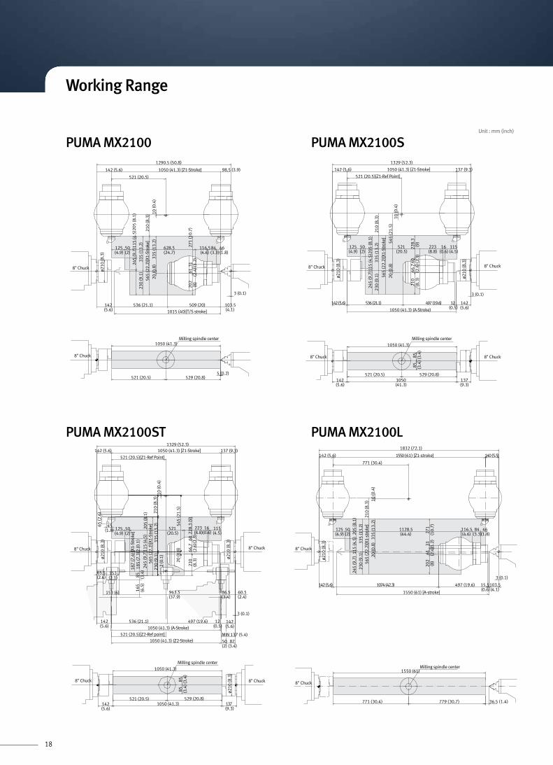
Working Range
18
335
(13.
2)23
0 (9
.1)
521 (20.5)
271
(10.
7)31 (1
.2)
61(2
.4)
202
(8)
10 (0
.4)
335
(13.
2)20
(0.8
)
1290.5 (50.8)
98.5 (3.9)1050 (41.3) [Z1-Stroke]142 (5.6)
245
(9.7
)115
(4.5
)205
(8.1
)
84(3.3)
116.5(4.6)
628.5(24.7)
50(2)
125(4.9)
46(1.8)
210
(8.3
)56
5 (2
2.2)
[X1-
Stro
ke]
ø210
(8.3
)
1015 (40)[T/S stroke]
103.5(4.1)
509 (20)536 (21.1)142(5.6)
3 (0.1)
8" Chuck
545
(21.
5)20
(0.8
)
210
(8.3
)33
5 (1
3.2)
230
(9.1
)
10 (0
.4)
521 (20.5)[Z1-Ref Point]
137 (9.3)1050 (41.3) [Z1-Stroke]142 (5.6)
ø210
(8.3
)
ø210
(8.3
)
1329 (52.3)
565
(22.
2)[X
1-St
roke
]
1050 (41.3) (A-Stroke)
3 (0.1)
21)6.91( 794)1.12( 635)6.5( 241(0.5)
142(5.6)
50(2)
125(4.9)
115(4.5)
16(0.6)
223(8.8)
521(20.5)
210
(8.3
)66
.7(2
.6)60 (2
.3)
228.
3(9
)
245
(9.7
)115
(4.5
)205
(8.1
)
8" Chuck 8" Chuck
137(9.3)
1050(41.3)
142(5.6)
529 (20.8)521 (20.5)
1050 (41.3)
85 (3.4
)85 (3
.4)
8" Chuck8" Chuck
Milling spindle center
5 (0.2)
1050 (41.3)
529 (20.8)521 (20.5)
8" Chuck
Milling spindle center
230
(9.1
)
521 (20.5)[Z1-Ref Point]
142(5.6)
12(0.5)
MIN 137 (5.4)
50(2)
87(3.4)
1329 (52.3)
125(4.9)
50(2)
223(8.8)
16(0.6)
115(4.5)
205
(8.1
)
545
(21.
5)
115
(4.5
)24
5 (9
.7)
187
(7.4
) [X1
-Str
oke]
185
(7.3
)2 (0
.1)
165
(6.5
)85 (3
.4)
228.
3 (9
)
335
(13.
2)
20 (0
.8)
2 (0
.1)
521(20.5)
60(2
.3)
66.7
(2.6
)21
0(8
.3) ø2
10 (8
.3)
ø210
(8.3
)
45(1.8)
65.5(2.6)
153(2.1)
153 (6)
65 (2
.6)
10 (0
.4)
137 (9.3)1050 (41.3) [Z1-Stroke]142 (5.6)
210
(8.3
)56
5 (2
2.2)
[X1-
Stro
ke]
497 (19.6)
963.5(37.9)
86.5(3.4)
60.5(2.4)
536 (21.1)142(5.6)
521 (20.5)[Z2-Ref point]1050 (41.3) (Z2-Stroke)
3 (0.1)
1050 (41.3) (A-Stroke)
8" Chuck 8" Chuck
7311050 (41.3)(9.3)
ø210
(8.3
)
529 (20.8)
85 (3.4
)85 (3
.4)
521 (20.5)142(5.6)
1050 (41.3)
8" Chuck 8" Chuck
Milling spindle center
1832 (72.1)
)5.5( 041]ekorts-1Z[ )16( 0551142 (5.6)
125(4.9)
)3.24( 4701)6.5( 241 497 (19.6) 15.5(0.6)
103.5(4.1)
3 (0.1)
1550 (61) [A-stroke]
1128.5(44.4)
116.5(4.6)
84(3.3)
46(1.8)
ø210
(8.3
)
245
(9.7
) 11
5 (4
.5)
205
(8.1
)33
5 (1
3.2)
230
(9.1
)
202
(8)
61 (2.4
)31 (1.2
)27
1(1
0.7)
10 (0
.4)
565
(22.
2)[X
1-st
roke
]
210
(8.3
)20
(0.8
) 3
35 (1
3.2)
8" Chuck
50(2)
771 (30.4)
)4.1( 5.63)7.03( 977)4.03( 177
1550 (61)Milling spindle center
8" Chuck
PUMA MX2100 PUMA MX2100S
PUMA MX2100ST PUMA MX2100L
Working Range
Unit : mm (inch)

19
45(1.8)65 (2
.6) 21
0 (8
.3)
335
(13.
2)23
0 (9
.1)
565
(22.
2)[X
1-St
roke
]
245(
9.7)
115
(4.5
) 20
5(8.
1)
125(4.9)
50(2)
322)2.04( 1201(8.8)
142(5.6)
1036 (40.8)
1550 (61) [A-stroke]497 (19.6)
(0.5)142(5.6)
3 (0.1)
)3.9( 731]ekorts-1Z[ )16( 0551)6.5( 241
771 (30.4) [Z1-Ref point]
1829 (72)
ø210
(8.3
)
10 (0
.4)
ø210
(8.3
)
210
(8.3
)66
.7(2
.6)60 (2
.4)
228.
3 (9
)
20 (0
.8)5
45 (2
1.5)
8" Chuck 8" Chuck
115(4.5)
16(0.6)
12
Milling spindle center
ø210
(8.3
)
ø210
(8.3
)
85 (3.4
)85
(3.4
)
8" Chuck 8" Chuck
)3.9( 731)16( 0551)6.5( 241
)7.03( 977)4.03( 177
1585 (62.4)140 (5.5) 130 (5.1)
1855 (73)
127 (5)
140(5.5)
65(2.6)
121)3.14( 8401(4.8)
86(3.4)
125(4.9)
194
(7.6
)58
(2.3
)60 (2.4
)31
8(1
2.5)21
7 (8
.5)
102
(4)
311
(12.
2)
370
(14.
6)26
0 (1
0.2)
240
(9.5
)
319
(12.
6)31
1 (1
2.2)
ø254
(10)
10" Chuck Tail Stock
778(30.6) [Z1-Ref. Point]
1585 (62.4) [Z1-Stroke]
20 (0.8
)
974(38.4)
156(6.1)
807 (31.8)
140 (5.5) 111 (4.4)
1836 (72.3)
1550 (61) [A-Stroke]
538(21.2)
156(6.1)
12(0.5)
45(1.8)
65 (2
.6)
1000(39.4)
95(3.7)
115(4.5)
170(6.7)
297
(11.
7)25 (1
)70 2.8)
238
(9.4
)
217
(8.5
)10
2 (4
)31
1 (1
2.2)
630
(24.
8) [X
1-St
roke
]
240
(9.5
)
ø254
(10)
ø254
(10)
100(3.9)
43(1.9)
10 (0
.4)
10" Chuck 10" Chuck
140(5.5)
65(2.6)
370
(14.
6)26
0 (1
0.2)
319
(12.
6)31
1 (1
2.2)
187
(7.4
)[X
1-St
roke
]
185
(7.3
)2 (0
.1)
165
(6.5
)85
(3.4
)
1021 (40.2)
)6.75( 5.3641)6( 351)6.2( 5.56
1036 (40.8)
1550 (61) [A-stroke]
1550 (61) [Z2-stroke]
771 (30.4) [Z2-Ref point]
497 (19.6)142 (5.6)
142 (5.6)
ø210
(8.3
)
ø210
(8.3
)
8" Chuck 8" Chuck
45(1.8)65 (2
.6)
125(4.9)
50(2)
)3.9( 731]ekorts-1Z[ )16( 0551)6.5( 241
771 (30.4) [Z1-Ref point]
1829 (72)
210
(8.3
)33
5 (1
3.2)
230
(9.1
)
565
(22.
2)[X
1-St
roke
]
245
(9.7
)115
(4.5
)205
(8.1
)
10 (0
.4)
223(8.8)
210
(8.3
)66
.7(2
.6)
60 (2.4
)22
8.3
(9)
20 (0
.8)5
45 (2
1.5) 115
(4.5)16
(0.6)
142 (5.6)12(0.5)
MIN 137 (5.4)
50(2)
87(3.4)
86.5(3.4)
60.5(2.4)
3 (0.1)
Milling spindle center
85 (3.4
)85 (3.4
)
142(5.6)
1550(61)
137(9.3)
)7.03( 977)4.03( 177
ø210
(8.3
)
ø210
(8.3
)
8" Chuck 8" Chuck
PUMA MX2100LS
PUMA MX2600 PUMA MX2600S
PUMA MX2100LST
Working Range
Unit : mm (inch)

20
778(30.6) [Z1-Ref. Point]
1585 (62.4) [Z1-Stroke]
807 (31.8)
140(5.5)
1515 (59.7) [Z2-Stroke]748 (29.5) [Z2-Ref. Point]
170(6.7)
87(3.4)
45 (1.8)
141(5.6)
43(1.7)
20 (0
.8)
1022 (40.2)156(6.1)
130(5.1)
1855 (73)
1550 (61) [A-Stroke]
2 (0
.1)
538 (21.2) 127(5)12
(0.5)
45(1.8)65
(2.6
)
140(5.5)
65(2.6)
1048 (41.3)(4.8)
86(3.4)
125(4.9)
194
(7.6
)58
(2.3
)60 (2.4
)31
8(1
2.5)
217
(8.5
)10
2 (4
)31
1 (1
2.2)
370
(14.
6)26
0 (1
0.2)
630
(24.
8) [X
1-St
roke
]24
0 (9
.5)
319
(12.
6)31
1 (1
2.2)
220
(8.7
) [X2
-Str
oke]
182.
5(7
.2)
100
(3.9
)21
8 (8
.6)2
(0.1
)
48 (1.9
) 152
(6)
68 (2.7
)
ø254
(10)
100(3.9)
43(1.7)
10 (0
.4)
170(6.7)
83 (3.3)
166(6.5)
767 (30.2)
1286(50.6)
140
(5.5
)32 (1
.3)
10" Chuck Tail Stock
2 (0
.1)
1515 (59.7) [Z2-Stroke]748 (29.5) [Z2-Ref. Point]
170 (6.7)
141(5.6)
43(1.7)
156 (6.1)1550 (61) [A-Stroke]
538 (21.2) 12(0.5)
45(1.8)65
(2.6
)
140(5.5)
65(2.6) 21
7 (8
.5)
102
(4)
311
(12.
2)
370
(14.
6)26
0 (1
0.2)
630
(24.
8) [X
1-St
roke
]24
0 (9
.5)
319
(12.
6)31
1 (1
2.2)
220
(8.7
) [X2
-Str
oke]
182.
5(7
.2)
100
(3.9
)21
8 (8
.6)2
(0.1
)
48 (1.9
)
ø254
(10)
100(3.9)
43(1.7)
10 (0
.4)
83 (3.3)
166(6.5)
767 (30.2)
140
(5.5
)32 (1
.3)
778(30.6) [Z1-Ref. Point]
1585 (62.4) [Z1-Stroke]
68(2.7)
93(3.7)
20 (0
.8)
974 (38.4)
807 (31.8)
140(5.5)
111(4.4)
1836 (72.3)
156(6.1)
1000(39.4)
95(3.7)
115(4.5)
170(6.7)
297
(11.
7)25 (1
)70 (2
.8)
238
(9.4
)
48 (1.9
)17
2(6
.8)
ø254
(10)
151 (5.9)
1238(48.7)
10" Chuck 10" Chuck
778 (30.6) [Z1-Ref. Point]
1585 (62.4) [Z1-Stroke]
807 (31.8)
160(6.3)
1875 (73.8)
45(1.8)
65 (2
.6)
110(4.3)
50.5(2)
326
(12.
8)
370
(14.
6)26
0 (1
0.2)
630
(24.
8) [X
1-St
roke
]
240
(9.5
)
304
(12)
326
(12.
8)
10 (0
.4)
118
(4.7
)186
(7.3
)
65(2.6)
160(6.3)
176.5(7)
20 (0.8
)
111(4.4)
95(3.7)
115(4.5)
170(6.7)
297
(11.
7)25 (1
)70 (2
.8)
238
(9.4
)
ø254
(10)
980 (38.6)
1550 (61) [A-Stroke]
973.5(38.3)
538 (21.2) 12(0.5)
156(6.1)
10" Chuck12" Chuck
778 (30.6) [Z1-Ref. Point]
1585 (62.4) [Z1-Stroke]
20 (0.8
)
807 (31.8)
160(6.3)
130(5.1)
1875 (73.8)
45(1.8)
65 (2
.6)
125(4.9)
60 (2.4
)31
8(1
2.5)
326
(12.
8)
370
(14.
6)26
0 (1
0.2)
630
(24.
8) [X
1-St
roke
]
240
(9.5
)
304
(12)
326
(12.
8)
10 (0
.4)
110(4.3)
50.5(2)
118
(4.7
)186
(7.3
)
1028(40.5)
65(2.6)
160(6.3)
)4.21(513ø
)4. 21( 513ø
127(5)
12(0.5)
538 (21.2)1021.5 (40.2)176.5(7)
1550 (61) [A-Stroke]
121(4.8)
86(3.4)
194
(7.6
)58
(2.3
)
12" Chuck Tail Stock
121
PUMA MX2600T PUMA MX2600ST
PUMA MX3100 PUMA MX3100S
Working Range
Unit : mm (inch)
21
65 (2.6
)163(
6.4)
2 (0
.1)
165(
6.5)
165(
6.5)
165(
6.5)
839(33.0)68(2.7)
202(8.0)
925(36.4)(Z2 Stroke)60(2.4)
35(1.4)
60 (2.4
)40
(1.6
)125
(4.9
)
50(2
.0)
192(
7.6)
70(2.8)130(5.1)
115(
4.5)
18(0.7)
123.5(4.9) (X
2-St
roke
) MT #4
27(1
.1)
138(
5.4)
165(
6.5)
197(7.8) 925(36.4)(Z2 Stroke) 65(2.6)
122(4.8)
935(36.8)(Z1 Stroke) 130(5.1)
1187(46.7)
63(2.5)
65(2.6)
815(32.1) 45(1.8)
90(3
.5)
192(
7.6)
45(1
.8)1
20(4
.7)
5(0.2)
5(0.2)
62(2.4)
62(2.4)
65(2.6)
815(32.1) 45(1.8)
35(1.4)
60 (2.4
)
48 (1.9
)11
7(4
.6)17
5(6
.9)
Ø
123.5(4.9)
(X2-
Stro
ke)
MT #4
15(0
.6)
22(0
.9)
71(2.8)
925(36.4)(Z2 Stroke) 191(7.5)
85(3
.3)
125
(4.9
)25
(1.0
)
80(3.1)
62(2.4)
12(0.5) 851(33.5)
35(1.4)
60 (2.4
)
59(2.3)
192(
7.6)
143(
5.6)
123.5(4.9)
Ø
(X2-
Stro
ke)
MT #4
27(1
.1)
165(
6.5)
90(3
.5)
192(
7.6)
65(2.6) 860(33.9)63
(2.5)925(36.4)(Z2 Stroke) 199(7.8)
122(4.8)
935(36.8)(Z1 Stroke) 130(5.1)
1187(46.7)
122(4.8)
935(36.8)(Z1 Stroke) 130(5.1)
1187(46.7)
122(4.8)
935(36.8)(Z1 Stroke) 130(5.1)
1187(46.7)
122(4.8)
935(36.8)(Z1 Stroke) 130(5.1)
1187(46.7)
48(1
.9)1
17(4
.6)
35(1.4)
60 (2.4
)13
8(5.
4)
62(2.4)
5(0.2)
123.5(4.9)
Ø
175(
6.9)
Ø17
5(6.
9)Ø
175(
6.9)
Ø
175(
6.9)
Ø
(X2-
Stro
ke)
MT #4
12
43(1.7)
130(5.1)
925(36.4)(Z2 Stroke) 132(5.2)
15(0
.6)
51 (2.0
)
22(0.9)
860(33.9)
35(1.4)
60 (2.4
)84
(3.3
)66 (2.6
)
123.5(4.9)
Ø
(X2-
Stro
ke)
MT #4
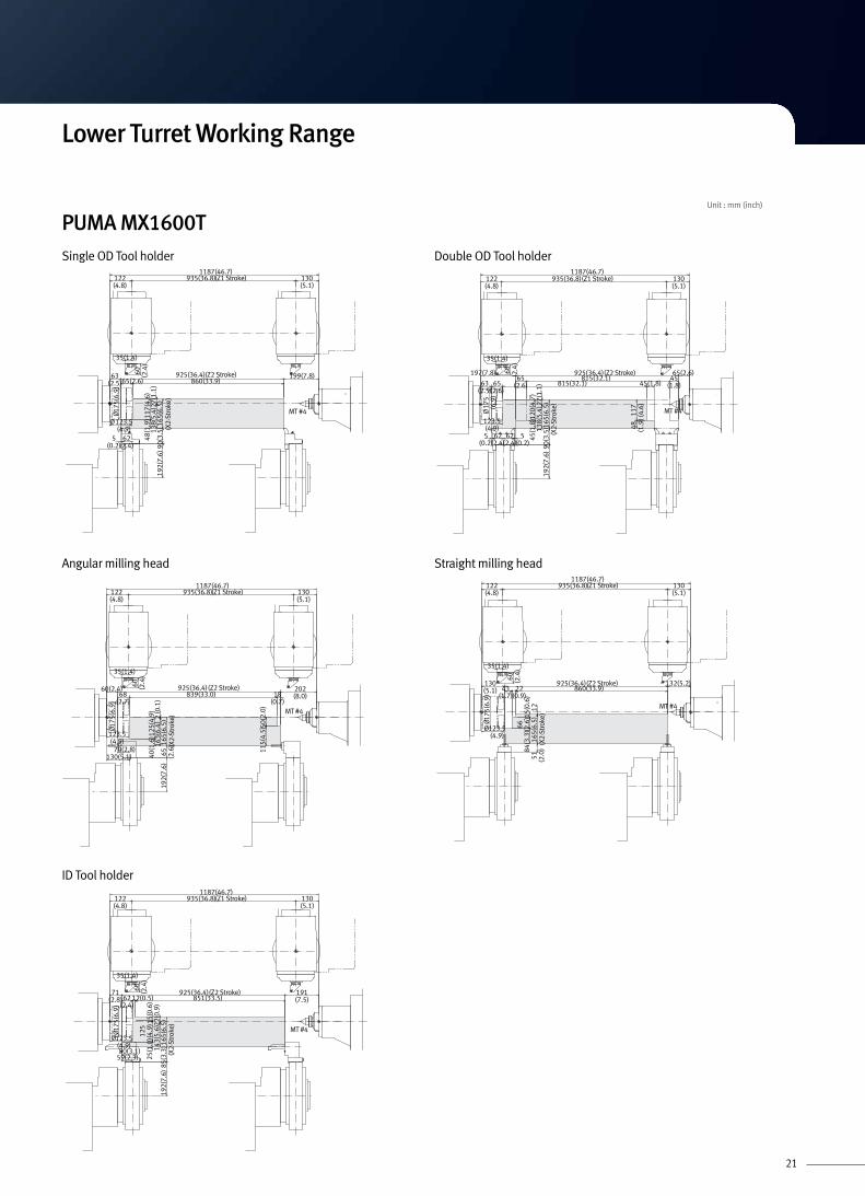
Lower Turret Working Range
PUMA MX1600TSingle OD Tool holder
Angular milling head
ID Tool holder
Double OD Tool holder
Straight milling head
Unit : mm (inch)

22
65 (2.6
)
163(
6.4)
2(0.
1)16
5(6.
5)
41 (1.6
)
125(4.9)
78(3.1)
782(31.3)12(0.5)
53(2.1) 794(31.3)128(5.0)
50(2.0)925(36.4)(Z2 Stroke)200(7.9)
35(1.4)
60
41(1
.6)10
9(4
.3)1
5(0.
6)
124
(4.9
)
192(
7.6)
70(2.8)
123.5(4.9)
Ø
70(2.8)
(X2-
Stro
ke)
27(1
.1)
138(
5.4)
165(
6.5)
197(7.8) 925(36.4) (Z2 Stroke) 53(2.1)
63(2.5)65(2.6) 785(30.9) 75(3.0)
75(3.0)
90 (3.5
)19
2(7.
6)
45(1
.8)
120(
4.7)
5(0.2)
5(0.2)
62(2.4)
62(2.4)
65(2.6) 785(30.9)
35(1.4)
60 (2.4
)
48 (1.9
)11
7(4
.6)
123.5(4.9)Ø
Ø
(X2-
Stro
ke)
16533
22
189 925(Z2 Stroke) 61
8585
25 2511
822
80
109 1922 817 6719 22 817 67
35
60
59
192
123.5Ø
(X2-
Stro
ke)
27(1
.1)
165(
6.5)
90(3
.5)
192(
7.6)
65(2.6)
785(30.9) 75(3.0)
197(7.8)
925(36.4)(Z2 Stroke) 53(2.1)
122(4.8) 935(36.8)(Z1 Stroke) 118(4.6)1175(46.3)
110(
4.3)
55(2
.2)
35(1.4)
60 (2.4
)
138(
5.4)
48 (1.9
)11
7(4
.6)
62(2.4)
5(0.2)
130(5.1)
175(
6.9)
Ø
123.5(4.9) (X
2-St
roke
)
165
12
8143 48
130 925(Z2 Stroke) 120
1551
22 812
35
60
848466
192
123.5Ø
(X2-
Stro
ke)
122(4.8) 935(36.8)(Z1 Stroke) 118(4.6)1175(46.3) 122(4.8) 935(36.8)(Z1 Stroke) 118(4.6)
1175(46.3)
122(4.8) 935(36.8)(Z1 Stroke) 118(4.6)1175(46.3)
122(4.8) 935(36.8)(Z1 Stroke) 118(4.6)1175(46.3)
175(
6.9)
175(
6.9)
Ø17
5(6.
9)Ø17
5(6.
9)Ø 17
5(6.
9)Ø
175(
6.9)
Ø
PUMA MX1600STSingle OD Tool holder
Angular milling head
ID Tool holder
Double OD Tool holder
Straight milling head
Lower Turret Working Range
Unit : mm (inch)

23
1329 (52.3) (Distance between spindle nose)
220 (8.7) 1050 (41.3) (Z2-axis travel)
862 (33.9)
22 (0.9)
61[98] (2.4[3.9])
106 (4.2)
100 (3.9)
100 (3.9)
862 (33.9)
1050 (41.3)
106 (4.2)
8"Chuck8"Chuck 37 (1
.5)
150
(5.9
)
120
(4.7
) 18
7 (7
.4)
(X2-
axis
trav
el)
93 [1
10] (
3.7[
4.3]
)
181 (7.1)
4[3] (0.2[0.1])
8"Chuck8"Chuck
872 (34.3)90 (3.5)
879 (34.6)90 (3.5)
1050 (41.3)
120
(4.7
) 1
87 (7
.4)
(X2-
axis
trav
el)
37 (1
.5)
150
(5.9
)
110
(4.3
)
1050 (41.3)(Z2-axis travel)220 (8.7)
1329 (52.3) (Distance between spindle nose)
64(2.5)
88 (3.5)
81 (3.2)
215 (8.5)
110
(4.3
)
59 (2.3)
3 (0.1)
8"Chuck8"Chuck
66(2.6)
1050 (41.3) (Z2-axis travel)
1329 (52.3) (Distance between spindle nose)
153 (6.0)
995 (39.2)55 (2.2)
783 (30.8)126 (5.0)147 (5.8)
521 (20.5) (Z2-Ref point)
142(5.6)
60 (2.4)
87 (3.4)126 (5.0)
48 (1
.9)
85 (3
.4)
187
(7.4
)(X
2-ax
is tr
avel
)
185
(7.3
)
2 (0
.1)
3 (0.1)
61 (2.4)
8"Chuck
85 (3
.4)
85 (3
.4)
58 (2
.3)
187
(7.4
)(X
2-ax
is tr
avel
)25 (1
.0)
3 (0.1)
60 (2.4)900 (35.4)48 (1.9)
137 (5.4)1050 (41.3)(Z2-axis travel)142(5.6)
1329 (52.3) (Distance between spindle nose)
8"Chuck
8"Chuck 8"Chuck
207 (8.2)
)0.3( 57)1.1( 72
72 (2.8)
885 (34.8)
1050 (41.3) (Z2-axis travel)
1329 (52.3) (Distance between spindle nose)
75 (3.0)885 (34.8)37 (1.5)
63 (2.5)
122 (4.8)1050 (41.3) (Z2-axis travel)147 (5.8)
123
(4.8
)
100
(3.9
) 18
7 (7
.4)
(X2-
axis
trav
el)
170
(6.7
) 17
(0.7
)
123
(4.8
)
3 (0.1)
2(0
.1)
PUMA MX2100ST / PUMA MX 2100TSingle OD Tool holder
Angular milling head
ID Tool holder
Double OD Tool holder
Straight milling head
Lower Turret Working Range
Unit : mm (inch)
24
8" Chuck 8" Chuck
181(7.1)
220(8.7) 100
(3.9)
1829 (72.0)
)3.2( 95)ekorts-2Z( )0.16( 0551
88 (3.5)
88 (3.5)
98 (3.9)
3 (0.1)
1362 (53.6)
1550 (61.0)
1362 (53.6)
17 (0
.7)
150
(5.9
)
110
(4.3
)
187
(7.4
)12
0 (4
.7) (X
2-st
roke
)37 (1
.5)
100(3.9)
8" Chuck8" Chuck
64(2.5)
220(8.7) 90
(3.5)
1829 (72.0)
)3.2( 95)ekorts-2Z( )0.16( 0551
88 (3.5)
81(3.2)
215(8.5)
3 (0.1)
1372 (54.0)
1550 (61.0)
1379 (54.3)
110
(4.3
)
65 (2
.6)
150
(5.9
)
110
(4.3
)
65 (2
.6)
187
(7.4
)12
0 (4
.7) (X
2-st
roke
)
37 (1
.5)
90(3.5)
8" Chuck 8" Chuck
66(2.6)
153 (6.0)
55 (2.2)
126 (5.0)147 (5.8)
142 (5.6) 771 (30.3) (Z2-Ref point)
1829 (72.0)
1550 (61.0) (Z2-stroke) 60 (2.4)
3 (0.1)
60(2.4)
126 (5.0) 87(3.4)
1495 (58.9)
1283 (50.5)
85 (3
.4)
185
(7.3
) 2
(0.1
)
2 (0
.1)
31 (1
.2)
187
(7.4
)(X
2-st
roke
)
8" Chuck 8" Chuck
142 (5.6)
48(1.9)
43 (1.7)
1829 (72.0)
1550 (61.0) (Z2-stroke) 137 (5.4)
3 (0.1)60 (2.4)1400 (55.1)
85 (3
.4)
27 (1
.1)
85 (3
.4)
187
(7.4
) 2
5 (1
.0)
58 (2
.3)
(X2-
stro
ke)
8" Chuck 8" Chuck
147(5.8)
207 (8.2)
27 (1.1) 63 (2.5)
1829 (72.0)
)8.2( 27)ekorts-2Z( )0.16( 0551
75 (3.0)
75(3.0)
159 (6.3)
3(0.1)
1385 (54.5)
1523 (60.0)
1385 (54.5)
32 (1
.3)
140
(5.5
)
170
(6.7
)
140
(5.5
)
187
(7.4
)10
0 (3
.9) (X
2-st
roke
)
17 (0
.7)
63(2.5)
120(4.7)
120(4.7)
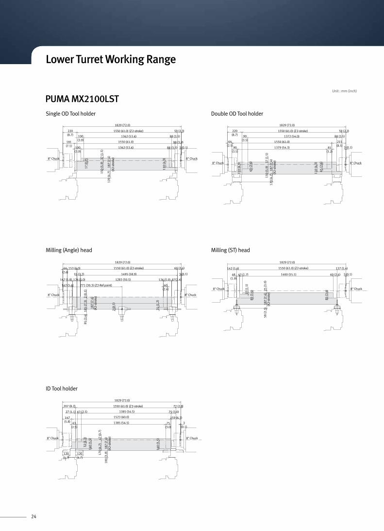
PUMA MX2100LSTSingle OD Tool holder
Milling (Angle) head
ID Tool holder
Double OD Tool holder
Milling (ST) head
Lower Turret Working Range
Unit : mm (inch)

25
1515 (59.7) (Z2-Stroke)
156 (6.1)156 (6.1)
220
(8.7
)
182.
5(7
.2)
ø254
(10.
0)
ø254
(10.
0)
100(3.9)
43(1.7)
143(5.6)
1244 (49.0)
130
(5.1
)
15(0.6)
7(0.3)
74(2.9)
247 (9.7)
32 (1
.3)
188
(7.4
)
34 (1.3
)27 (1.1
)15
9(6
.3)
87 (3.4)41(1.6)
56 (2.2
)164
(6.5
)
)8.5( 741)3.27( 6381)2.3( 18
(X2-
Stro
ke) 10"
Chuck10" Chuck
1515 (59.7) (Z2-Stroke)
651)1.6( 651(6.1)
220
(8.7
)
182.
5(7
.2)
ø254
(10.
0)
ø254
(10.
0)
100(3.9)
43(1.7)
116(4.6)
1244 (49.0)
130
(5.1
)
74 (2.9)247 (9.7)
32 (1
.3)
188
(7.4
)
56 (2.2
)
87(3.4)
68(2.7)
56 (2.2
)16
4(6
.5)
132
(5.2
)32 (1.3
)
7 (0.3)15 (0.6)
154 (6.1)
)4.3( 78)7.2( 86 270(10.6)
1090 (42.9)
81 (3.2) )8.5( 741)3.27( 6381
(X2-
Stro
ke) 10" Chuck10"
Chuck
1515 (59.7) (Z2-Stroke)
748 (29.5)(Z2-Ref. Point)
170 (6.7)
68 (2.7)
93 (3.7)
43 (1.7)
156 (6.1)
2 (0
.1)
156(6.1)
220
(8.7
)
182.
5(7
.2)
100
(3.9
)21
8(8
.6)
2 (0
.1)
48 (1.9
)
ø254
(10.
0)
ø254
(10.
0)
100 (3.9)
43 (1.7)
151 (5.9)
83 (3.3)
166 (6.5) 767 (30.2)
62 (2.4)74 (2.9)
48 (1.9
)17
2(6
.8)
140
(5.5
)32 (1.3
)
141 (5.6) 1238 (48.7)
141(5.6)
1238 (48.7)
(X2-
Stro
ke)
10" Chuck 10"Chuck
1515 (59.7) (Z2-Stroke)
748 (29.5) (Z2-Ref. Point)
170 (6.7)
156 (6.1)
2 (0
.1)
156(6.1)
220
(8.7
)
182.
5(7
.2)
58 (2.3
)40
(1.6
)
ø254
(10.
0)
ø254
(10.
0)
100 (3.9)
43 (1.7)
151 (5.9)
767 (30.2)
8(0.3)
41(1.6)
47 (1.9)
94 (3.7)
8(0.3)
60 (2.4)
128
(5.0
)53 (2.1
)
128
(5.0
)58 (2
.3)
34 (1.3
)
135(5.3)
1263 (49.7)
7(0
.3)32
(1.3
)
)8.5( 741)3.27( 6381)2.3( 18
(X2-
Stro
ke)
10" Chuck10"Chuck
1515 (59.7) (Z2-Stroke)
156 (6.1) 156(6.1)
220
(8.7
)
182.
5(7
.2)
ø254
(10.
0)
ø254
(10.
0)
100 (3.9)
43(1.7)
123
(4.8
)
81(3.2)
240(9.5)
25 (1
.0)
195
(7.7
)
33 (1.3
)
131
(5.2
)
24 (0.9
)
80(3.2)
120(4.7)
15 (0.6)
32 (1.3
)
120(4.7)
90(3.5)
35(1.4)
33 (1.3
)18
7(7
.4)
11(0.4)
11(0.4)
35(1.4)
138(5.4)
80(3.2)
1251 (49.3)
228(9.0)
1161(45.7)
81(3.2)
741)3.27( 6381(5.8)
(X2-
Stro
ke) 10"
Chuck10" Chuck
PUMA MX2600ST / PUMA MX 2600TSingle OD Tool holder
Milling (Angle) head
Boring Bar holder
Double OD Tool holder
Milling (ST) head
Lower Turret Working Range
Unit : mm (inch)

26
210(8.3)
85 (3.4)85 (3.4)
170 (6.7)
330
(13.0)
235(9.3)
37(1.5) 100(3.9)
20 (0.8)
Spindle Center
610 (24.0)
115 (4.5) 115 (4.5)
230 (9.1)
100(3.9)
330
(13.0)
115 (4.5) 115 (4.5)
230 (9.1)
270
(10.6)
240(9.5)
85 (3.4)
85 (3.4)
170 (6.7)
Spindle Center
20 (0.8)
545 (21.5)
(Y -S troke)12
0°120°
30°
90°90°
30°
174.5
(6.9)(3.9)
324.5 (12.8)
100450 (17.7) (X1-Stroke)
125.5 (4.9)
49.07
(1.9)(1.9)
(1.9)(1.9)
49.07
49.0749.07
(Gauge Line)
Spindle CL
85(3.3)
85(3.3)
400 (15.7)
50 (2.0)
99.07 (3.9)
49.07
(1.9) 450 (17.7) (X1-Stroke)
Spindle CL 170 (6.7)
85(3.3)
85(3.3)
170 (6.7)
(Y-Stroke)
(Y-Stroke)
PUMA MX1600Y-axis working range
PUMA MX2100Y-axis working range
PUMA MX2600 / 3100Y-axis working range B-axis rotating range
B-axis, Y-axis Working Range
Unit : mm (inch)

27
PUMA MX1600
PUMA MX2100
PUMA MX2600
Lower Turret Interference Diagram
Unit : mm (inch)
ø217 (8.5)
100
(3.9)72(2.8) 58(2.3)
102 (4.0)
37(1.5)
150(5.9)
40(1.6)
80(3.2)
ø280 (11.0)
ø178(7.0)
ø217 (8.5)
ø241(9.5)ø40 (1.6)
ø592(23.3)(Max.swing dia)
187 (7.4)(X2-axis travel)
120(4.7)
165(6.5)
165(6.5)
100(3.9)
ø300 (11.8) (Lower turret : Max.turning dia)
85 (3
.4)
Max
. ø16
(0.6
)
.
90(3.5)
40(1.6)
ø376 (14.8) (Lower turret : Max. tunning dia.)
188(7.4)
32(1.3)
220 (8.7)(X2-STROKE)
182.5(7.2)
182.5(7.2)
128
(5.0
)
ø672 (26.5)(Max.swing dia.)
100 (3.9)
95 (3
.7)
58
ø40 (1.6)(Max. boring bar dia.)
ø20(0.8)
ø266(10.5)
ø254 (10.0)
ø266 (10.5)
ø20 (0.8) (Max. end mill dia.)
ø177
.5 (7
.0)
182.5 (7.2)
102 (4.0)
ø250
(9.8)
27(1.1)138 (5.4)
30(1.2)
60(2.4)
165 (6.5) (X2-Stroke)192 (7.6)192 (7.6)90 (3.5) 90 (3.5)
Ø185 (7.3)Ø158 (6.2)
Ø32 (1.3)
Ø170 (6.7)Ø276 (10.9) (Lower turret;Max. turning dia)
Ø170 (6.7)
Ø198 (7.8)
Ø158 (6.2) Ø178 (7.0)
65
85
Ø32 (1.3) Ø605 (23.8) (Max. swing dia)
SPINDLE CENTER
28
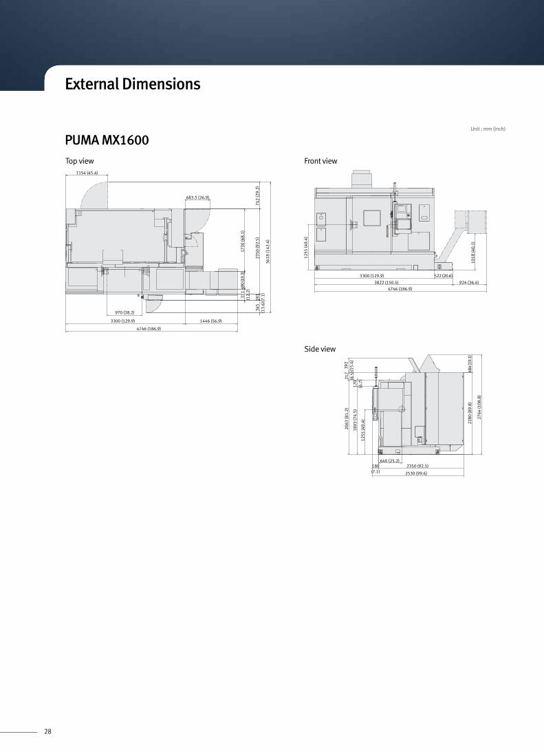
3300 (129.9) 522 (20.6)
3822 (150.5) 924 (36.4)4746 (186.9)
640 (25.2)180(7.1)
2350 (92.5)
2530 (99.6)
1255
(49.
4)
217
(8.5
)17
0(6
.7)
1893
(74.
5)
1255
(49.
4) 2280
(89.
8)
2764
(108
.8)
484
(19.
1)
2063
(81.
2)39
2(1
5.4)
1018
(40.
1)
1154 (45.4)
683.5 (26.9)
1446 (56.9)3300 (129.9)
4746 (186.9)
970 (38.2)
742
(29.
2)23
50 (9
2.5)
3618
(142
.4)
181
(7.1
)34
5(1
3.6)
1730
(68.
1)49
0 (1
9.3)
311
(12.
2)
Side view
Front view
PUMA MX1600Top view
External Dimensions
Unit : mm (inch)

29
225 (8.9)
2300 (90.6)
2525 (99.4)
640 (25.2)
2155
(84.
8)18
18 (7
1.6)
(2.4
)275
(10.
8)12
45 (4
9.0)
062)2.001( 5452
(10.
2)28
05 (1
10.4
)
10 (0
.4)
)7.73( 759)2.351( 0983)2.12( 935)8.091( 7484
1071
(42.
2)
5386 (212.1)
1189 (46.8))9.85( 6941)2.351( 0983
405
(15.
9))7.82( 037
)4.99( 525236
60 (1
44.1
)
438
(17.
2)44
0 (1
7.3)
1647
(64.
8)
629(24.8)
5(0.2)
411(16.2)
5386 (212.1)
1329 (52.3)
750 (29.5)(L-Door open)
440 (17.3)(R-Door open)
1372 (54.0)
3890 (153.2) 1496 (58.9)
405
(15.
9)
438
(17.
2)44
0(1
7.3)
1647
(64.
8))9.34( 5111
)4.99( 525240
45 (1
59.3
)
1189 (46.8)
629(24.8)
5(0.2)
411(16.2)
5386 (212.1)146 (5.8)
750 (29.5)(L-Door open)
440 (17.3)(R-Door open)
1329 (52.3)
597 (23.5)539 (21.2)
1071
(42.
2)
5386 (212.1)
140
(5.5
)21
55 (8
4.8)
225 (8.9) 2300 (90.6)640 (25.2)
3640 (143.3)
)9.34( 5111)4.99( 5252
275
(10.
8)62 (2
.4)
1818
(71.
6)12
45 (4
9.0)
2545
(100
.2)
2805
(110
.4)
10 (0
.4)
6214
0 (5
.5)
1372 (54.0)
260
(10.
2)
PUMA MX2100 (40 Tools)
Top view
Side view
Side view
Front view
Front view
PUMA MX2100 (80 Tools)
Top view
External Dimensions
Unit : mm (inch)

30
1689 (66.5)73
0 (2
8.7)
2490
(98.
0)36
25 (1
42.7
)40
5(1
5.9)
411
(16.
2)44
0(1
7.3)
1639
(64.
5)
1829 (72.0)
910 (35.8)(L-door open)
800 (31.5)(R-door open)
779 (30.7)5(0.2)
761 (30.0)
1451 (57.1))1.75( 1541)6.591( 9694
)4.83( 579)6.591( 9694
1072
(42.
2)
5944 (234.0) 514 (20.2)6458 (254.3)
10 (0
.4)12
45 (4
9.0)
1818
(71.
6) (2
.4)27
5 (1
0.8)
140
(5.5
)21
55 (8
4.8)
2545
(100
.2)
(10.
2)28
05 (1
10.4
)
225(8.9)
2265 (89.2)
2490 (98.0)
640 (25.2)
1689 (66.5))1.75( 1541)6.591( 9694
411
(16.
2)40
5(1
5.9)
)6.07( 4971)0.89( 094246
89 (1
84.6
)
440
(17.
3)16
39 (6
4.5)
1829 (72.0)
910 (35.8)(L-door open)
800 (31.5)(R-door open)
761(30.0)
5(0.2)
779(30.7)
)4.83( 579)6.591( 9694
1072
(42.
2)
)2.02( 415)0.432( 44956458 (254.3)
10 (0
.4)
1245
(49.
0)
2545
(100
.2)
2953
(116
.3)
409
(16.
1)
1818
(71.
6)(2
.4)27
5(1
0.8)
2155
(84.
8)
225(8.9)
2265(89.2)
3742 (147.3))3.94( 2521)0.89( 0942
640 (25.2)
260
62
6214
0 (5
.5)
1451 (57.1)
PUMA MX2100LST (40 Tools)
Top view Front view
Front view
Side view
Side view
PUMA MX2100LST (80 Tools)
Top view
External Dimensions
Unit : mm (inch)

31
)5.86( 0471)0.06( 4251)3.37( 1681)9.95( 2251)8.102( 5215
392
(15.
4)26
82 (1
05.6
)38
1(1
5.0)
490
(19.
3)17
57 (6
9.2)
3762
(148
.1)
R 455.5
(17.9)
R 633.5(24.9)
R 742(29.2)
744 (29.3)5˚
775 (30.5)
6647 (261.7)
892 (35.1) (L-door open)842 (33.2) (R-door open)
)7.22( 775)2.73( 549)8.102( 5215
1200
(47.
2)18
27 (7
1.9)
6070 (239.0)6647 (261.7)
217 (8.5)
2410 (94.9)
2565
(101
.0)
(17.
6)30
11.3
(118
.6)
2626.7 (103.4)
660 (26.0)
1868
(73.
5)18
05 (7
1.1)
1265
(49.
8)
2625
(103
.4)
378
(14.
9)49
0(1
9.3)
1757
(69.
2)
5° 393
(15.
5)
R633.5 (24.9)
R453.5
(17.9)
)6.16( 5651)8.102( 5215
893 (35.2) 1350 (53.2) 2882 (113.5)
1200
(47.
2)(1
9.4)
4710
(185
.4)
742 (29.2)
R742 (29.2)
R 492 (19.4)
)2.73( 549)8.102( 5215620 (24.4)6070 (239.0)
6690 (263.4)
1200
(47.
2)18
27 (7
1.9)
1818 (71.6)
892 (35.1)(L-door open)
842 (33.2)(R-door open)
1526(60.1)
1079(42.5)
5(0.2)
1200(47.2)
131551.8)
Stroke: 1355 (53.4)
FL 0
660 (26.0)215(8.5)
2410 (94.9)
2625 (103.4)
15 (0
.6)
1820
(71.
7)
2580
(101
.6)
(17.
5)30
25 (1
19.1
)
Stro
ke: 1
80 (7
.1)
627
(24.
7)
446.
3
492
1610 (63.4)
627
(24.
7)
445
1265
(49.
8)
PUMA MX2600 / 3100 (40 Tools)
Top view Front view
Front view
Side view
Side view
PUMA MX2600 / 3100 (80 Tools)
Top view
External Dimensions
Unit : mm (inch)
32
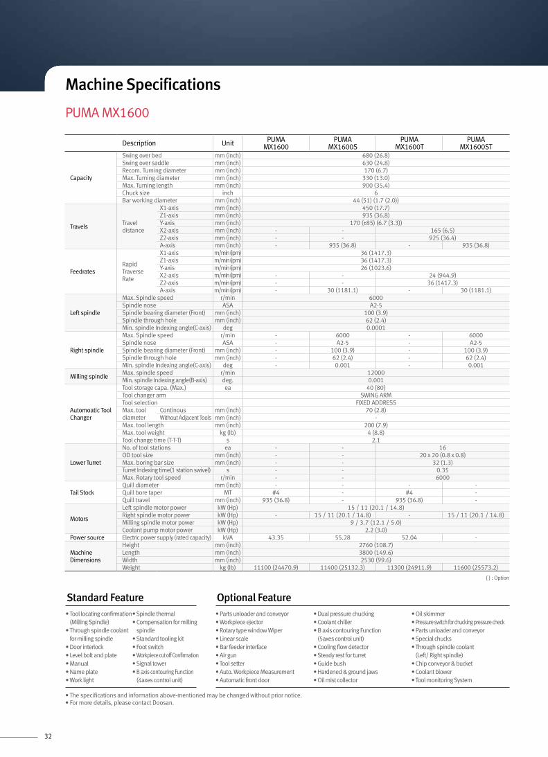
PUMA MX1600
Description Unit PUMAMX1600
PUMAMX1600S
PUMAMX1600T
PUMAMX1600ST
Capacity
Swing over bed mm (inch) 680 (26.8)Swing over saddle mm (inch) 630 (24.8)Recom. Turning diameter mm (inch) 170 (6.7)Max. Turning diameter mm (inch) 330 (13.0)Max. Turning length mm (inch) 900 (35.4)Chuck size inch 6Bar working diameter mm (inch) 44 (51) (1.7 (2.0))
TravelsTravel distance
X1-axis mm (inch) 450 (17.7)Z1-axis mm (inch) 935 (36.8)Y-axis mm (inch) 170 (±85) (6.7 (3.3))X2-axis mm (inch) - - 165 (6.5)Z2-axis mm (inch) - - 925 (36.4)A-axis mm (inch) - 935 (36.8) - 935 (36.8)
FeedratesRapid Traverse Rate
X1-axis m/min (ipm) 36 (1417.3)Z1-axis m/min (ipm) 36 (1417.3)Y-axis m/min (ipm) 26 (1023.6)X2-axis m/min (ipm) - - 24 (944.9)Z2-axis m/min (ipm) - - 36 (1417.3)A-axis m/min (ipm) - 30 (1181.1) - 30 (1181.1)
Left spindle
Max. Spindle speed r/min 6000Spindle nose ASA A2-5Spindle bearing diameter (Front) mm (inch) 100 (3.9)Spindle through hole mm (inch) 62 (2.4)Min. spindle Indexing angle(C-axis) deg 0.0001
Right spindle
Max. Spindle speed r/min - 6000 - 6000Spindle nose ASA - A2-5 - A2-5Spindle bearing diameter (Front) mm (inch) - 100 (3.9) - 100 (3.9)Spindle through hole mm (inch) - 62 (2.4) - 62 (2.4)Min. spindle Indexing angle(C-axis) deg - 0.001 - 0.001
Milling spindleMax. spindle speed r/min 12000Min. spindle Indexing angle(B-axis) deg. 0.001
Automoatic Tool Changer
Tool storage capa. (Max.) ea 40 {80}Tool changer arm SWING ARMTool selection FIXED ADDRESSMax. tool diameter
Continous mm (inch) 70 (2.8)Without Adjacent Tools mm (inch) -
Max. tool length mm (inch) 200 (7.9)Max. tool weight kg (Ib) 4 (8.8)Tool change time (T-T-T) s 2.1
Lower Turret
No. of tool stations ea - - 16OD tool size mm (inch) - - 20 x 20 (0.8 x 0.8)Max. boring bar size mm (inch) - - 32 (1.3)Turret Indexing time(1 station swivel) s - - 0.35Max. Rotary tool speed r/min - - 6000
Tail StockQuill diameter mm (inch) - - - -Quill bore taper MT #4 - #4 -Quill travel mm (inch) 935 (36.8) - 935 (36.8) -
Motors
Left spindle motor power kW (Hp) 15 / 11 (20.1 / 14.8)Right spindle motor power kW (Hp) - 15 / 11 (20.1 / 14.8) - 15 / 11 (20.1 / 14.8)Milling spindle motor power kW (Hp) 9 / 3.7 (12.1 / 5.0)Coolant pump motor power kW (Hp) 2.2 (3.0)
Power source Electric power supply (rated capacity) kVA 43.35 55.28 52.04 -
Machine Dimensions
Height mm (inch) 2760 (108.7)Length mm (inch) 3800 (149.6)Width mm (inch) 2530 (99.6)Weight kg (Ib) 11100 (24470.9) 11400 (25132.3) 11300 (24911.9) 11600 (25573.2)
{ } : Option
Standard Feature• Tool locating confirmation
(Milling Spindle)• Through spindle coolant
for milling spindle• Door interlock• Level bolt and plate• Manual• Name plate• Work light
• Spindle thermal • Compensation for milling
spindle• Standard tooling kit• Foot switch• Workpiece cut off Confirmation• Signal tower• B axis contouring Function
(4axes control unit)
• Parts unloader and conveyor• Workpiece ejector• Rotary type window Wiper• Linear scale• Bar feeder interface• Air gun• Tool setter• Auto. Workpiece Measurement• Automatic front door
• Dual pressure chucking• Coolant chiller• B axis contouring Function
(5axes control unit)• Cooling flow detector• Steady rest for turret • Guide bush• Hardened & ground jaws• Oil mist collector
• Oil skimmer• Pressure switch for chucking pressure check• Parts unloader and conveyor• Special chucks• Through spindle coolant
(Left/ Right spindle)• Chip conveyor & bucket• Coolant blower• Tool monitoring System
Optional Feature
Machine Specifications
• The specifications and information above-mentioned may be changed without prior notice.• For more details, please contact Doosan.

33
PUMA MX2100
{ } : Option
Description Unit PUMAMX2100[L]
PUMAMX2100S[LS]
PUMAMX2100T[LT]
PUMAMX2100ST[LST]
Capacity
Swing over bed mm (inch) 750 (29.5)Swing over saddle mm (inch) 650 (25.6)Recom. Turning diameter mm (inch) 210 (8.3)Max. Turning diameter mm (inch) 540 (21.3)Max. Turning length mm (inch) 1020 [1520] (40.2 [59.8])Chuck size inch 8Bar working diameter mm (inch) 65 (2.6)
TravelsTravel distance
X1-axis mm (inch) - 565 (22.2)Z1-axis mm (inch) - 1050 [1550] (41.3 [61.0])Y-axis mm (inch) 170 (±85) (6.7 (3.3))X2-axis mm (inch) - - 187 (7.4)Z2-axis mm (inch) - - 1050 [1550] (41.3 [61.0])A-axis mm (inch) - 1050 [1550] (41.3 [61.0]) - 1050 [1550] (41.3 [61.0])
FeedratesRapid Traverse Rate
X1-axis m/min (ipm) 36 (1417.3)Z1-axis m/min (ipm) 36 (1417.3)Y-axis m/min (ipm) 26 (1023.6)X2-axis m/min (ipm) - - 24 (944.9)Z2-axis m/min (ipm) - - 36 (1417.3)A-axis m/min (ipm) - 30 (1181.1) - 30 (1181.1)
Left spindle
Max. Spindle speed r/min 5000Spindle nose ASA A2-6Spindle bearing diameter (Front) mm (inch) 110 (4.3)Spindle through hole mm (inch) 76 (3.0)Min. spindle Indexing angle(C-axis) deg 0.0001
Right spindle
Max. Spindle speed r/min - 5000 - 5000Spindle nose ASA - A2-6 - A2-6Spindle bearing diameter (Front) mm (inch) - 110 (4.3) - 110 (4.3)Spindle through hole mm (inch) - 76 (3.0) - 76 (3.0)Min. spindle Indexing angle(C-axis) deg - 0.001 - 0.001
Milling spindleMax. spindle speed r/min 12000Min. spindle Indexing angle(B-axis) deg. 0.001
Automoatic Tool Changer
Tool storage capa. (Max.) ea 40 {80}Tool changer arm SWING ARMTool selection FIXED ADDRESSTool shank -Max. tool diameter
Continous mm (inch) 90 (3.5)Without Adjacent Tools mm (inch) 120 (4.7)
Max. tool length kg (Ib) 300 (661.4)Max. tool weight s 9Tool change time (T-T-T) s 2.0
Lower Turret
No. of tool stations ea - - 12OD tool size mm (inch) - - 25 x 25 (1.0 x 1.0)Max. boring bar size mm (inch) - - 40 (1.6)Turret Indexing time(1 station swivel) s - - 0.2Max. Rotary tool speed r/min - - 5000
Tail StockQuill bore taper MT #4 - #4 -Quill travel mm (inch) 1050 [1550] (41.3 [61.0]) - 1050 [1550] (41.3 [61.0]) -
Motors
Left spindle motor power kW (Hp) 22 / 18.5 (29.5 / 24.8)Right spindle motor power kW (Hp) - 22 / 18.5 (29.5 / 24.8) - 22 / 18.5 (29.5 / 24.8)Milling spindle motor power kW (Hp) 18.5 / 15 / 11 (24.8 / 20.1 / 14.8)Coolant pump motor power kW (Hp) 2.2 (3.0)
Power source Electric power supply (rated capacity) kVA 50 [53] 56.7 [75] 50 [53] 88 [89.8]
Machine Dimensions
Height mm (inch) 2805 (110.4)Length mm (inch) 4850 [5945] (190.9 [234.1])Width mm (inch) 2525 [2490] (99.4 [98.0])
Weight kg (Ib)11500 [12800]
(25352.8 [28218.8])11800 [13800]
(26014.2 [30423.3])11700 [13700]
(25793.7 [30202.9])12000 [14000]
(26455.1 [30864.3])
Standard Feature• Air blast (for chuck)• Coolant supply equipment• Door interlock• Standard work tools
(including holders)• Hyd. chuck & actuating cylinder• Hydraulic power unit• Level bolt and plate• Soft jaws
• Spindle head cooling System• Work light• Through spindle coolant
for milling spindle (Milling spindle)
• Servo driven tail stock (except S/ST type machine)
• Signal tower (yellow, red, green)
• Air gun• Automatic door with safety device• Automatic power off• Tool setter• Bar feeder• Bar puller• Chip Conveyor & Bucket• Coolant blower• Dual chucking pressure
• Hardened & ground jaws• Oil mist collector• Oil skimmer• Pressure switch for chucking
pressure check• Parts unloader and conveyor• Special chucks• Through spindle coolant
(Left/Right spindle)
• Work ejector• Linear scale• Minimum Quantity Lubrication
(MQL) system• Coolant chiller• Gantry loader• Servo driven steady rest
(except S/ST type machine)• Tool monitoring system
Optional Feature
Machine Specifications
• The specifications and information above-mentioned may be changed without prior notice.• For more details, please contact Doosan.

34
PUMA MX2600 / MX3100
Description Unit PUMAMX2600
PUMAMX3100
PUMAMX2600S
PUMAMX3100S
PUMAMX2600T
PUMAMX2600ST
Capacity
Swing over bed mm (inch) 1000 (39.4)Swing over saddle mm (inch) 700 (27.6)Recom. Turning diameter mm (inch) 255 (10.0) 310 (12.2) 255 (10.0) 310 (12.2) 255 (10.0)Max. Turning diameter mm (inch) 760 (29.9)Max. Turning length mm (inch) 1540 (60.6)Chuck size inch 10 12 10 12 10Bar working diameter mm (inch) 76 (3.0) 102 (4.0) 76 (3.0) 102 (4.0) 76 (3.0)
TravelsTravel distance
X1-axis mm (inch) 630 (24.8)Z1-axis mm (inch) 1585 (62.4)Y-axis mm (inch) 230 (±115) (9.1 (4.5))X2-axis mm (inch) - - - - 220 (8.7)Z2-axis mm (inch) - - - - 1515 (59.6)A-axis mm (inch) - - 1550 (61.0) - 1550 (61.0)
FeedratesRapid Traverse Rate
X1-axis m/min (ipm) 36 (1417.3)Z1-axis m/min (ipm) 36 (1417.3)Y-axis m/min (ipm) 26 (1023.6)X2-axis m/min (ipm) - - - - 24 (944.9)Z2-axis m/min (ipm) - - - - 36 (1417.3)A-axis m/min (ipm) - - 30 (1181.1) - 30 (1181.1)
Left spindle
Max. Spindle speed r/min 4000 3000 4000 3000 4000Spindle nose ASA A2-8 A2-11 A2-8 A2-11 A2-8Spindle bearing diameter (Front) mm (inch) 130 (5.1) 160 (6.3) 130 (5.1) 160 (6.3) 130 (5.1)Spindle through hole mm (inch) 86 (3.4) 115 (4.5) 86 (3.4) 115 (4.5) 86 (3.4)Min. spindle Indexing angle(C-axis) deg 0.0001
Right spindle
Max. Spindle speed r/min - - 4000 - 4000Spindle nose ASA - - A2-8 - A2-8Spindle bearing diameter (Front) mm (inch) - - 130 (5.1) - 130 (5.1)Spindle through hole mm (inch) - - 86 (3.4) - 86 (3.4)Min. spindle Indexing angle(C-axis) deg - - 0.001 - 0.001
Milling spindleMax. spindle speed r/min 12000Min. spindle Indexing angle(B-axis) deg. 0.001
Automoatic Tool Changer
Tool storage capa. (Max.) ea 40 {80}Tool changer arm SWING ARMTool selection FIXED ADDRESSMax. tool diameter
Continous mm (inch) 90 (3.5)Without Adjacent Tools mm (inch) 130 (5.1)
Max. tool length kg (Ib) 400 (881.8)Max. tool weight s 10Tool change time (T-T-T) s 2.0
Lower Turret
No. of tool stations ea - - - - 12OD tool size mm (inch) - - - - 25 x 25 (1.0 x 1.0)Max. boring bar size mm (inch) - - - - 40 (1.6)Turret Indexing time(1 station swivel) s - - - - 0.2Max. Rotary tool speed r/min - - - - 4000
Tail StockQuill bore taper MT #5 - #5 - -Quill travel mm (inch) 1550 (61.0) - 1550 (61.0) - -
Motors
Left spindle motor power kW (Hp)26 / 22
(34.9 / 29.5)30 / 25
(40.2 / 33.5)26 / 22
(34.9 / 29.5)30 / 25
(40.2 / 33.5)26 / 22
(34.9 / 29.5)
Right spindle motor power kW (Hp) - -26 / 22
(34.9 / 29.5)-
26 / 22(34.9 / 29.5)
Milling spindle motor power kW (Hp) 22 / 18.5 / 15 (29.5 / 24.8 / 20.1)Coolant pump motor power kW (Hp) 2.2 (3.0)
Power source Electric power supply (rated capacity) kVA 70 80 90 100 70 100
Machine Dimensions
Height mm (inch) 3025 (119.1)Length mm (inch) 5125 (201.8)Width mm (inch) 2625 (103.3)Weight kg (Ib) 13900 (30643.8) 14600 (32187.0) 13900 (30643.8) 14600 (32187.0) 14900 (32848.4) 15500 (34171.1)
Standard Feature• Air blast• Coolant chiller• Door interlock• Standard work tools
(including holders)• Hyd. chuck & actuating cylinder• Hydraulic power unit• Level bolt and plate• Soft jaws
• Spindle head cooling system• Work light• Through spindle coolant
for milling spindle• Servo driven tail stock
(except S/ST type machine)• Signal tower
(yellow, red, green)
• Air gun• Automatic door with safety device• Automatic power off• Tool setter• Bar feeder• Bar puller• Chip Conveyor & Bucket• Coolant blower• Dual chucking pressure
• Hardened & ground jaws• Oil mist collector• Oil skimmer• Pressure switch for chucking
pressure check• Parts unloader and conveyor• Special chucks• Through spindle coolant
(Left/Right spindle)
• Work ejector• Linear scale• Minimum Quantity Lubrication
(MQL) system• Coolant Chiller• Gantry loader• Servo driven steady rest
(except T/ST type machine)• Tool monitoring system
Optional Feature{ } : Option
Machine Specifications
• The specifications and information above-mentioned may be changed without prior notice.• For more details, please contact Doosan.

35
Fanuc 31i
AXES CONTROL- Controlled path 1 path / 2 path- Controlled axes X1, Z1, C1, Y, B, A, X2, Z2, C2- Simultaneous controlled axes
4 (5-Only for Fanuc 31i-A5 / B5)axes- Angular axis control- Backlash compensation 0 ~ ±9999 pulses- Backlash compensation for each rapid traverse
and cutting feed- Chamfering on/off- Synchronous / Composite control- Superimposed Control- HRV2 control- Inch / Metric conversion- Interlock All axis / each axis- Least input command 0.001 / 0.000 1 mm/inch- Machine lock All axis / each axis- Mirror image- Position switch- Servo off- Stored pitch error compensation- Stored stroke check 1- Torque control- Interference chek for rotary area- Unexpected disturbance torque detection function
OPERATION- DNC operation (Reader/puncher interface is required)- Reference position shift
PROGRAM INPUT- 3D coordinate conversion- Addition of custom macro common variables
#100~#199, #500~#999- Canned cycle for turning- Circular interpolation by R programming- Coordinate system setting G50- Coordinate system shift- Custom macro- Decimal point programming- Diameter/radius programming (X axis)- Direct drawing dimension programming- Direct input of coordinate system shift- G code system A- G code system B/C- Input unit 10 time multiply- Label skip- Macro executor- Manual absolute on and off- Maximum program dimension ±9 digit- Multiple repetitive canned cycle G70 - G76- Multiple repetitive canned cycle II- Optional block skip 1 piece- Plane selection G17, G18, G19- Program file name 32 characters- Programmable data input G10- Sequence number N8 digit- SUB program call 10 folds nested- Tape code : ISO / EIA auto recognition
EIA RS422/ISO840- Tape format for FANUC Series15- Work coordinate system G52 - G59
TOOL FUNCTION / TOOL COMPENSATION- Automatic tool offset- Direct input of offset value measured- Direct input of offset value measured B- T - code function T2 + 3 digits- Tool geometry / wear compensation- Tool life management- Tool nose radius compensation- Tool offset G43, G44, G49- Tool offset pairs Upper : ±6 digits : 400 pairs Lower : ±6 digits : 99 pairs- Tool offset value counter input- Y-axis offset
DATA INPUT/OUTPUT- External key input- External data input- External work number search 15 points- Memory card input/output- Reader/puncher interface CH1.interface- RS232C interface- Automatic data backup (자동 데이터 백업)- Screen hard copy
OTHERS- Cycle start and lamp- Display unit 10.4" Color LCD- Feed hold and lamp- MDI unit for 10.4" LCD- NC and servo ready- PMC system PMC-31iA- Reset / rewind
INTERFACE FUNCTION- Ethernet function Embedded ethernet
TOOL FUNCTION / TOOL COMPENSATION- Tool monitoring system
EDITING OPERATION- Extended part program editing- Number of registered programs 1000 ea- Part program storage size 512 Kbyte(Note) Specify total of part program storage size of each path- Memory card program edit & operation- Program protect
SETTING AND DISPLAY- Actual cutting feedrate display- Alarm history display- Periodic maintenance screen- Display of spindle speed and T code at all screens- Optional path name display (Only for 2path)- Multi-language display English- Operation history display- Run hours / part count display- Self-diagnosis function- Servo setting screen- Spindle setting screen
OPERATION- DNC Operation with Memory card- Buffer register- Dry run- Handle incremental feed X1, X10, X100- Program restart- Wrong operation prevention- JOG feed - Manual pulse generator (Portable MPG) 1 ea- Manual reference position return- Single block- Tool direction handle feed (G68.1)
INTERPOLATION FUNCTIONS- Nano interpolation- 1st. Reference position return Manual, G28- 2nd. reference position return G30- 3rd/4th reference position return- AICC (Number of lookhead block : 30 Blocks)- Balance cutting (Only for 2 path)- Continuous threading- Cylindrical interpolation- Dwell (per sec.) G04- Multiple threading- Polar coordinate interpolation- Reference position return check G27- Polygon machining with two spindle- Skip G31- Thread cutting / Synchronous cutting- Torque limit skip
FEED FUNCTION- Automatic acceleration / deceleration- Cutting feedrate clamp- Feed per minute- Feed per revolution- Feedrate override (10% unit) 0 - 200 %- Jog feed override (10% unit) 0-2000 mm/min.- Manual per revolution feed- Override cancel- Rapid traverse override F0, 25, 100 %
AUXILIARY / SPINDLE SPEED FUNCTION- Spindle orientation- Constant surface speed control- M-code function M3 digits- Multi spindle control- Rigid tapping- S-code function S4 / S5 digits- Spindle serial output S4 / S5 digits- Spindle speed override 0 - 150 %- Spindle synchronous control- Actual spindle speed output
OPERATION- Manual handle interruption- Tool retract and recover
INTERPOLATION FUNCTIONS- Circular threading- Multi step skip- Variable lead threading- High speed skip
PROGRAM INPUT- Addition of workpiece coordinate system pair 48 pairs- Interruption type custom macro- Pattern data input- Work coordinate system preset- Optional block skip 9 piece (Includs software operators panel)
FEED FUNCTION- AI Contour control (Look-ahead block no. is MAX.200) G5.1 Q1- External deceleration- Feed stop
EDITING OPERATION- Part program storage size 1MB / 2MB- Play back
DATA INPUT/OUTPUT- Data server- DNC control
CONTOURING FUNCTION- Tool center point control by 5-axes:
just on FANUC 31i-A5 / B5- High Speed machining (600 blocks)
ROBOT INTERFACE- Robot interface with PMC I/O module
(Hardware between PMC I/O mudules)- Robot interface with PROFIBUS-DP
SETTING AND DISPLAY- Directory display of floppy cassette
OPTIONAL SPECIFICATIONS
OPERATION GUIDANCE FUNCTION- EZ Guide-i (Conversational Programming Solution)
NC Unit Specifications

Head OfficeDoosan Tower 20th FL., 18-12, Euljiro-6Ga, Jung-Gu, Seoul, Korea 100-730 Tel : ++82-2-3398-8693 / 8671 / 8680 Fax : ++82-2-3398-8699
Doosan Infracore America Corp.19A Chapin Rd. Pine Brook, NJ 07058, U.S.A. Tel : ++1-973-618-2500 Fax : ++1-973-618-2501
Doosan Infracore Germany GmbHEmdener Strasse 24 D-41540 Dormagen Germany Tel : ++49-2133-5067-100 Fax : ++49-2133-5067-001
Doosan Infracore Yantai Co., LTD13 Building, 140 Tianlin Road, Xuhui District, Shanghai, China (200233) Tel : ++86-21-6440-3384 (808, 805) Fax : ++86-21-6440-3389
- The specifications and information above-mentioned may be changed without prior notice.- For more details, please contact Doosan.
http://www.doosaninfracore.com/machinetools/
EN 140829SU