Embed Size (px)
Citation preview

MULTI-RING SDH NETWORK DESIGN OVER
OPTICAL MESH NETWORKS
A THESIS
SUBMITTED TO THE DEPARTMENT OF ELECTRICAL AND
ELECTRONICS ENGINEERING AND SCIENCES
OF BILKENT UNIVERSITY
IN PARTIAL FULFILLMENT OF THE REQUIREMENTS
FOR THE DEGREE OF
MASTER OF SCIENCE
By
Tuba Akıncılar Tan
January 2002

ii
I certify that I have read this thesis and that in my opinion it is fully adequate,
in scope and in quality, as a thesis for the degree of Master of Science.
Assist. Prof. Dr. Ezhan Karaşan (Supervisor)
I certify that I have read this thesis and that in my opinion it is fully adequate,
in scope and in quality, as a thesis for the degree of Master of Science.
Assist. Prof. Dr. Murat Alanyalı
I certify that I have read this thesis and that in my opinion it is fully adequate,
in scope and in quality, as a thesis for the degree of Master of Science.
Assist. Prof. Dr. Nail Akar
Approved for the Institute of Engineering and Science
Prof. Dr. Mehmet Baray
Director of Institute of Engineering and Sciences

iii
ABSTRACT
MULTI-RING SDH NETWORK DESIGN OVER
OPTICAL MESH NETWORKS
Tuba Akıncılar Tan
M.S. in Electrical and Electronics Engineering
Supervisor: Assist. Prof. Dr. Ezhan Karaşan
January 2002
The evolution of networks in telecommunications has brought on the
importance of design techniques to obtain survivable and cost-effective transportation
networks. In this thesis, we study Synchronous Digital Hierarchy (SDH) ring design
problem with an interconnected multi-ring architecture overlaid over an optical mesh
network. We decouple the problem into two sub-problems: the first problem is the
SDH ring selection, and the second problem is the mapping of these rings onto the
physical mesh topology. In this structure, the logical topology consists of SDH
Add/Drop Multiplexers (ADMs) and Digital Cross-Connects (DXCs), and the
physical topology consists of Optical Cross-Connects (OXCs).
The ring selection problem is to choose the rings that give minimum inter-ring
traffic in the network. Since inter-ring traffic increases the network cost and
complexity, we aim to minimize the inter-ring traffic. We propose a greedy heuristic
algorithm for this problem that finds a solution subject to the constraint that the
number of nodes on each ring is limited. Numerical results on the ring design problem
are presented for different topologies.

iv
Once the logical topology is obtained, resilient mapping of SDH rings onto the
mesh physical topology is formulated as a Mixed Integer Linear Programming
(MILP) problem. In order to guarantee proper operation of SDH ring protection
against all single failures, each link on an SDH ring must be mapped onto a lightpath
which is link and node disjoint from all other lightpaths comprising the same ring.
The objective of this mapping is to minimize the total fiber cost in the network. We
also apply a post-processing algorithm to eliminate redundant rings. The post-
processing algorithm is very useful to reduce the cost. We evaluate the performance
of our design algorithm for different networks.
Keywords: SDH over optical networks, multi-ring SDH networks, ring selection,
resilient ring mapping over mesh networks

v
ÖZET
OPTİK AĞ ŞEBEKELER ÜZERİNE ÇOKLU HALKA SDH
ŞEBEKE TASARIMI
Tuba Akıncılar Tan
Elektrik ve Elektronik Mühendisliği Bölümü Yüksek Lisans
Tez Yöneticisi: Yrd. Doç. Dr. Ezhan Karaşan
Ocak 2002
Telekomünikasyonda şebeke evrimi, uzun ömürlü ve uygun maliyetli ulaşım
ağları elde etmek için tasarım tekniklerinin gelişmesine neden olmuştur. Bu tezde,
optik ağ şebekesi üzerinde birbirine bağlı çoklu halka yapısındaki eşzamanlı sayısal
hiyerarşi halka tasarımı üzerinde çalışılmıştır. Problem iki alt probleme ayrılmıştır: ilk
problem eşzamanlı sayısal hiyerarşi halka seçimi, ikinci problem ise bu halkaların
fiziksel ağ topolojisi üzerine haritalanmasıdır. Bu yapıda, mantıksal topoloji
eşzamanlı sayısal hiyerarşi ekle/çıkar çoklayıcılarından ve sayısal çapraz
bağlantılardan oluşur, fiziksel topoloji ise optik çapraz bağlantılardan oluşur.
Halka seçim problemi, şebekedeki en düşük halkalar arası trafiği verecek
halkaları seçmektir. Halkalar arası trafik, şebekenin maliyetini ve karmaşıklığını
artırdığı için, halkalar arası trafiği en aza indirmeyi hedefledik. Bu problem için her
halkadaki düğüm sayısı sınırlamasına sahip bir çözüm bulan buluşsal bir algoritma
öngörüldü. Farklı topolojiler için halka tasarım probleminin sayısal sonuçları
sunulmuştur.
Mantıksal topoloji elde edildikten sonra, eşzamanlı sayısal hiyerarşi
halkalarının fiziksel ağ topolojisi üzerine esnek haritalanması karma tamsayılı
doğrusal programlama ile formüle edildi. Bütün tek hatalara karşı eşzamanlı sayısal

vi
hiyerarşi halka korumasının uygun çalışmasını garanti altına almak için, bir eşzamanlı
sayısal hiyerarşi halkasının her bağlantısı aynı halkayı kapsayan diğer tüm
ışıkyollarından, bağlantı ve düğüm ayrık olacak şekilde bir ışıkyoluna haritalandı. Bu
haritalamanın hedefi şebekedeki toplam fiber maliyetini en aza indirgemektir. Ayrıca,
gereksiz halkaları ortadan kaldırmak için bir işlem sonrası algoritma uyguladık. Bu
işlem sonrası algoritma maliyeti düşürmek için çok kullanışlıdır. Tasarım
algoritmamızın performansını farklı şebekeler için değerlendirdik.
Anahtar Kelimeler: optik şebekeler üzerinde eş zamanlı sayısal hiyerarşi, çoklu halka
eşzamanlı sayısal hiyerarşi şebekeleri, halka seçimi, ağ şebekeleri üzerine esnek halka
haritalama

vii
ACKNOWLEDGMENTS
I would like to express my deep gratitude to my supervisor Assoc. Prof. Dr. Ezhan
Karaşan for his guidance, suggestions and invaluable encouragement in my graduate
education and throughout the development of this thesis.
I would like to thank Assoc. Prof. Dr. Murat Alanyalı and Assoc. Prof. Dr. Nail
Akar for their invaluable comments and suggestions on my thesis.
I would also like to thank Tolga Akar for his support on this thesis.
I am grateful to my friends Ahmet Murat Bağcı and Egemen Değer Kavak for
their helps besides their friendship.
Special thanks to my love Kaan Tan for his love, understanding, trust,
encouragement and support whenever I needed.
Finally, I would like to thank my mother Sevim Akıncılar for her endless love,
trust, encouragement, and support throughout my life.

viii
Contents
1 INTRODUCTION 1
2 EVOLUTIONS TOWARDS SDH 6
2.1 Transmission Hierarchy…………………………………………………...6
2.1.1 The Problem in PDH…………………………………………….7
2.1.2 The Solution in SDH…………………………………………….9
2.1.3 Introduction to WDM…………………………………………..11
2.2 Survivability……………………………………………………………...13
2.3 SDH Ring Protection……………………………………………………..16
2.3.1 SDH Network Architectures…………………………………...17
2.3.2 SDH Ring Protection Mechanisms…………………………….20
2.4 SDH Ring Design Problem………………………………………………25

ix
2.5 Survey of Previous Work on SDH Ring Design…………………………33
2.6 Summary of Proposed SDH Ring Design Algorithm……………………37
3 SDH RING DESIGN PROBLEM 41
3.1 Logical Topology………………………………………………………...43
3.2 Greedy Heuristic Algorithm for Ring Selection………………………….46
3.2.1 Face Merging…………………………………………………...47
3.3 Numerical Results………………………………………………………..53
4 EMBEDDING IN A PHYSICAL TOPOLOGY PROBLEM 62
4.1 MILP Formulation……………………………………………………….63
4.2 Post Processing…………………………………………………………...66
4.3 Numerical Results………………………………………………………..68
5 CONCLUSION 82

x
List of Figures
1.1 Evolution of optical transmission fiber cost…………………………………...2
2.1 An Optical Fiber……………………………………………………………….7
2.2 PDH Multiplexing……………………………………………………………..8
2.3 ADM Structure……………………………………………………………….10
2.4 DXC Structure………………………………………………………………..10
2.5 (a)Classic Transport Protocol (b)Dense Wavelength Division Multiplexing..11
2.6 An IP over ATM over SDH network………………………………………...14
2.7 A SDH layer over optical layer………………………………………………15
2.8 A point-to-point SDH link……………………………………………………17
2.9 A linear drop and insert SDH network……………………………………….17
2.10 A SDH Ring Network………………………………………………………..18
2.11 Multi-Ring SDH Topology…………………………………………………..19
2.12 A mesh topology of SDH network…………………………………………...20
2.13 Two-fiber MS-SPRing……………………………………………………….22
2.14 Four-fiber MS-SPRing……………………………………………………….22
2.15 Two-fiber MS-SPRing Protection under link failure condition……………...23

xi
2.16 SNCP Protection under link failure condition……………………………….24
2.17 Physical and logical topologies for a SDH network over the DWDM layer (a)
The physical topology (b) The logical topology……………………………..26
2.18 (a) SDH networks with 4 rings (b) SDH networks with 2 rings (c) Unwanted
situation, Node 5 is disconnected…………………………………………….28
2.19 An example of mapping a logical ring onto physical topology (The logical
links of rings are mapped onto not physical link disjoint paths)……………..31
3.1 A SDH Network over the optical (DWDM) layer…………………………...42
3.2 A multi-ring SDH topology with several inter-ring traffic…………………..43
3.3 A physical topology with OXC and ADM nodes……………………………44
3.4 Planar logical graph with link weights……………………………………….45
3.5 The constructed faces of a planar mesh network…………………………….46
3.6 An example of routing in a multi-face topology……………………………..48
3.7 Minimum number of rings path for 1st shortest path…………………………49
3.8 Minimum number of rings path for 2nd shortest path………………………...50
3.9 An example of a network topology (a) A planar logical graph with faces (b)
Face adjacency graph………………………………………………………..51
3.10 An example of disconnected graph after face merging………………………52
3.11 The first example: physical topology with 32-nodes………………………...53
3.12 The second example: physical topology with 32-nodes……………………..54
3.13 The third example: physical topology with 32-nodes………………………..54
3.14 Logical Topology obtained for 13-nodes SDH network of the first example..55
3.15 Logical Topology obtained for 13-nodes SDH network of the second
example………………………………………………………………………55
3.16 Logical Topology obtained for 13-nodes SDH network of the third example.56

xii
3.17 Ring Merges for the first example (a) Nmax=6, (b) Nmax=5, (c) Nmax=4…57
3.18 Ring Merges for the second example (a)Nmax=6, (b)Nmax=5, (c)Nmax=4..59
3.19 Ring Merges for the third example (a) Nmax=6, (b) Nmax=5, (c) Nmax=4...60
4.1 First example of post-processing……………………………………………..66
4.2 Second example of post-processing………………………………………….67
4.3 Third example of post-processing……………………………………………67
4.4 Mapping of logical rings of first example (Nmax=6)………………………..68
4.5 Mapping of logical rings of first example (Nmax=5)………………………..69
4.6 Mapping of logical rings of first example (Nmax=4)………………………..70
4.7 Mapping of logical rings of second example (Nmax=6)……………………..72
4.8 Mapping of logical rings of second example (Nmax=5)……………………..73
4.9 Mapping of logical rings of second example (Nmax=4)……………………..74
4.10 Mapping of logical rings of third example (Nmax=6)……………………….75
4.11 Mapping of logical rings of third example (Nmax=5)……………………….76
4.12 Mapping of logical rings of third example (Nmax=4)……………………….77

xiii
List of Tables
2.1 Four different Plesiochronous digital hierarchies……………………………..7
2.2 Standardized Frame Rates……………………………………………………11
2.3 The Ring Protection Architectures…………………………………………...21
3.1 Inter-ring traffic changes for a demand set for different size
constraints…………………………………………………………………….61
4.1 Fiber costs of mapped SDH Rings before and after post processing………...80
4.2 Average shortest path comparisons for different maximum node number of
three examples………………………………………………………………..81

To My Father...

1
Chapter 1 INTRODUCTION
Today’s transport networks must cope with ever increasing traffic inflation by the high-
capacity and reliable systems. The demand is increased by many different factors. The
rapid growth of the Internet, voice, data, videoconferencing, and private networking
services consumes large amounts of bandwidth. Especially Internet connections load the
telephone network enormously. There are also increasing technological revolutions on the
industry, finance, education, medicine, government and especially business intranet
applications. All these factors increase the need for bandwidth in networks. Optical fiber
transmission has played an important role in carrying high bit rates traffic. Traditionally,
before optical fibers were available, coaxial cables were used in long distance transport
networks. The cost of coaxial cables is dependent of the bandwidth of the cable. With the
introduction of optical technology in transmission network, the transmission cost was
reduced drastically over the past years as seen in Figure 1.1.
Optical fibers can carry much higher bit rates than copper cables. Thus, it is preferred
medium for transmission data in long distance transmission networks. The cost of the
optical fiber is independent of the bit rate carried by it. The widespread use of optical
fibers and technological improvements in fiber technology reduced the cost in today’s
networks.

2
Figure 1.1 Evolution of optical transmission fiber cost
Until the mid 1980s, Plesiochronous Digital Hierarchy (PDH) systems were used in
transmission networks. In the mid 1980s, telecom operators needed a high capacity,
flexible transmission system, so researchers started to define a new, high capacity
worldwide system. In the 1990s, Synchronous Digital Hierarchy (SDH) transmission
system compatible with existing PDH systems were started to be used by telecom
operators. In SDH transmission systems, Time Division Multiplexing (TDM) technology
is used to multiplex lower order bit rates into higher order bit rates. Today, the highest
transmission rate commercially used in SDH telecommunication networks is 10 Gb/s, and
40 Gb/s is being developed. Another technology has been deployed commercially since
1996 is called Wavelength Division Multiplexing (WDM). WDM transmission systems
allow multiplexing multiple optical channels on a single fiber at different wavelengths. It
has become the preferred transmission technology in long distance transport networks at
the end of 1990s. Today’s Dense Wavelength Division Multiplex (DWDM) systems can
multiplex 16, 32, 64, 80, and 96 channels each carrying 10 Gb/s onto a single fiber and
1000
100
10
1
Transmission Cost per Mb/s.km
(relative)
1975 1980 1985 1990 1995 2000
45 Mb/s
90 Mb/s
400 Mb/s
1,2 Mb/s
2,5 Mb/s 10 Mb/s
Time

3
160 channels DWDM systems are being developed. Currently, WDM is widely used in
point-to-point configurations to offer fiber cost savings in long distance backbone
architectures.
The network design process is influenced by the resulting network architectures. The
network can be consisting of many layers interoperating with each other. In the design
strategies different layering structures are used. The most important point is to offer
reliable uninterrupted services to the customer by telecommunications operators.
Typically, the failure of a single optical fiber link may cause loss of hundred thousand or
more calls or data connections in progress. Therefore, network survivability is a major
factor that affects the design of the networks to handle all types of failures. In order to
provide high quality services, the traffic should be restored within a small period.
Different layers have their own protection mechanisms. SDH and WDM layers can be
designed to work with other layers or they can operate directly over fiber independent on
the other layers to handle protection and restoration.
In this thesis, we work with the SDH over WDM topology. In SDH networks, point-to-
point connections are widely replaced by ring structures. A ring network is a 2-connected
structure and there are two separate paths between any pairs of nodes. This provides
resilience to any single failure. When a failure occurs on a link, the traffic is rerouted
over the paths on the reserved capacity of the ring. This protection is called as ring
protection. The most popular protection architecture of SDH is self-healing rings in
network protection and we will discuss these structures in more detail in the next chapter.
Since ring networks have several advantages such as fast restoration time, simple
operationally and cost affectivity, the usage of ring networks are now very common for
survivability design. In this thesis we only consider single link failures, and the protection
is provided by only the SDH layer.
SDH networks consist of several functional equipments: Terminal Multiplexers (TMs) in
point-to-point connections, Add/Drop Multiplexers (ADMs) in individual nodes to
terminate a part of traffic and add some traffic to pass through, and Digital Cross-
Connects (DXCs) to interconnect multiple rings. Digital cross-connects are used to cross-
connect inter-ring traffic between multiple rings where inter-ring traffic is defined as the
set of demands such that source node belongs to one ring and the destination node
belongs to another ring.
In this thesis we discuss and formulate two interrelated problems in the transport network
design. First part is the logical ring design, and second part is the mapping of these rings

4
onto the physical topology. In the first step, we connect ADM nodes with each other
using a multi-ring architecture. We select the rings to be deployed such that the resulting
interconnected multi-ring structure can be used to route all demands between their source
and destination ADMs and each ring satisfies node size constraints. The objective of this
first part of the design process is to obtain a multi-ring architecture that results in the
minimum inter-ring traffic. By minimizing the inter-ring traffic, we aim to reduce the cost
of the DXC equipments and decrease the complexity of the network. After all SDH rings
are determined, we try to map these rings onto the physical topology. This mapping has
to be done in such a way that each link on a ring is mapped onto an optical path, called a
lightpath, which is physically diverse, i.e., node and link disjoint, from all other lightpaths
corresponding to other SDH links on the same ring. This is required since SDH rings
have to cope up with all possible single link or node failures. The objective of this
mapping is the minimization of the cost of fibers used by each ring.
We discuss the evolution of transport network architectures and new technologies in
Chapter 2. We also present the protection architectures of SDH over DWDM networks
and provide the advantages of ring protection. Then, we describe the ring design problem.
Finally we make a summary and comparison of different network design techniques in
the literature.
In Chapter 3, we propose a greedy heuristic algorithm for solving the ring design
problem. The first step in the design process is to generate the logical graph, which has
the ADMs as its nodes and possible connections between ADMs as its links. This graph
is constructed such that it has a planar embedding. The faces, i.e., simple rings, of this
topology are used as the starting solution for the heuristic ring design algorithm. There
are two main constraints in the logical ring design process. First, each ring can have a
maximum number of nodes. The second constraint is that the rings must ensure the
2-connectivity. In the logical ring design, the objective is to minimize inter-ring traffic in
the network. In this chapter we also provide some numerical examples for the application
of this algorithm.
Once the logical ring design problem is solved, we represent the mapping of logical rings
onto the physical topology in Chapter 4. We formulate the mapping of logical rings onto
the physical topology as a Mixed Integer Linear Programming (MILP) problem. We map
each logical ring onto disjoint physical links and nodes. The objective of the mapping is
to minimize the total fiber costs in the network. We compare our solution on different

5
topologies. Finally, we conclude our thesis with some improvements for future work in
Chapter 5.

6
Chapter 2 EVOLUTION TOWARDS SDH
In this chapter, the evolution towards the transmission system based on SDH will be
discussed. We present the transmission hierarchy from PDH to DWDM. We also discuss
the survivability issue and SDH network protection architectures; especially, ring
protection. SDH ring design problem is also considered extensively. Finally, we present a
literature survey.
2.1 Transmission Hierarchy
Telecom operators must cope with explosion of data traffic. In the 1970’s, first order
multiplexing is used, where only 30 speech channels are multiplexed. When the need for
high capacity systems increased, higher order digital transmission rates, multiplexing
even more speech channels were designed.
The transmission medium of the networks can be coaxial cables, copper, radio links,
satellites, or fiber optic medium that has been widely used in recent years. Before optical
fibers were available, coaxial cables were widely used in traditional long distance
transmission networks. In coaxial cables, as bandwidth increases, the quality and
resultant cost of cables also increase. Therefore it was so important to design the network
carefully for the capacity need. In contrast, the optical fibers, consisting of a glass
cylinder surrounded by a cladding glass tube, can carry information at very high bit rates,
e.g.; exceeding 1 Tb/s (Figure 2.1).

7
Core Cladding Protective jacket
Figure 2.1 An Optical Fiber
2.1.1 The Problem in PDH
The set of standards that explains the higher order transmission rates is referred as the
PDH. As fast developments occur in the transmission systems, PDH systems become
expensive and complex solutions due to some weak points.
The first problem is different PDHs defined in North America, Europe, Japan and Trans
Atlantic as shown in Table 2.1. These different hierarchies were an unwanted situation
and a new common worldwide hierarchy of higher order signals, SDH, was defined.
Hierarchical
Level
North America
(Kb/s)
Europe
(Kb/s)
Japan
(Kb/s)
Trans Atlantic
(Kb/s)
0 64 64 64 64
1 1544 2048 1544 2048
2 6312 8448 6312 6312
3 44736 34368 32064 44736
4 139264 139264 97728 139264
Table 2.1 Four different Plesiochronous digital hierarchies
The second problem of PDH is back-to-back multiplexing. If we insert a tributary signal
into the higher order signal, the inverse procedure should be done. Therefore, lots of
processing is needed and it increases the number of equipment in the network, such as

8
2 Mb/s
140 Mb/s
8 / 2
34 / 8
140 /
34
34 Mb/s
8 Mb/s
34 / 8
140 /
34
34 Mb/s
2 Mb/s
Line
Node A Node B
8 / 2
8 Mb/s
multiplexers and demultiplexers. Thus, the networks become expensive and complex
solution.
In PDH transmission systems, it is impossible to remove a 2 Mb/s signal from a 140 Mb/s
directly. Three multiplexing steps are required to obtain a 2 Mb/s lower order signal from
a 140 Mb/s higher order signal. The procedure is shown in the Figure 2.2.
Figure 2.2 PDH multiplexing

9
2.1.2 The Solution in SDH
The SDH (Synchronous Digital Hierarchy), which results from SONET (Synchronous
Optical NETwork) is an international standard for high-speed telecommunication over
optical/electrical networks, which can transport digital signals in variable capacities.
Since Telecommunication Operators first introduced digital transmission into the
telephone network in the 1970’s, the demand for transmission capacity and higher order
transmission rates has rapidly increased in the telephone network. As a result, the existing
transmission systems based on PDH became a weak transmission system and a new, high
capacity, flexible transmission system was needed to overcome the limitations presented
by PDH networks. To cope with the disadvantages of PDH, the new, high capacity and flexible transmission
system was developed in 1980’s. It became a standard in ANSI (American National
Standards Institute) referred to as the SONET in 1984. In 1988, CCITT (International
Consultative Committee on Telephony & Telegraphy) agreed a standard on this
transmission system as the SDH with certain changes to define a worldwide system. The
first SDH standards were approved by the ITU-T in November 1988 and
recommendations G707, G708 and G709 were published in the CCITT Blue Book in
1989. They define the rate, frame and multiplexing processes and the SDH became an
international, high-rate telecommunication network standard.
SDH uses one worldwide hierarchy and is based on optical fiber transmission links in
order to take advantage of the high bandwidth and reliability of the fiber optic medium. It
is also compatible with the existing PDHs. Unlike PDH systems, SDH can directly add
lower order signals to higher order signals or drop them from higher order rates, without
having to multiplex/demultiplex.
A network element can be configured as Terminal Multiplexer (TM), Add and Drop
Multiplexer (ADM) or as a hub. Also, Digital Cross-Connect (DXC) network elements
are used in a traditional network.
The Add/Drop multiplexing reduces the number of elements, so it results in less system
cost. An ADM used to add/drop lower order rate traffic can be seen in the Figure 2.3.

10
Line Line
Tributaries
ADM
Add Drop
Higher Order Signal
Higher Order Signal
Lower Order Signal
Figure 2.3 ADM Structure
Digital Cross-Connects, which are bigger and having more capacity systems than an
ADM, are usually used in the backbone network or at the gateway nodes between two
regional and backbone networks. This equipment has internal cross connection
capabilities and very similar functionality to ADMs, but they are very expensive with
respect to ADMs. In the DXCs, signals can be switched between two lines, or between
tributaries, or line to tributaries by switching functionality of the equipment (Figure 2.4).
Figure 2.4 DXC Structure
The standardized SDH transmission frames, called Synchronous Transport Modules of
Nth hierarchical level (STM-N) which correspond to Synchronous Transport Signals of
SONET are shown in Table 2.2.

11
(a) One Traffic Channel per Fiber
STM-16/STM-64 Tx
STM-16/STM-64 Rx
Table 2.2 Standardized Frame Rates
SDH systems are practical and produce powerful management architecture; this easy
management results in high reliability and flexibility. This Time Division Multiplexing
(TDM) based transport systems are widely used to provide high capacity transmission for
voice, data and leased-line applications.
2.1.3 Introduction to WDM
For high-speed networks, to satisfy the increasing demands and to use the optical
switching and routing, the new technology, WDM has become the preferred transmission
technology for point-to-point connections.
WDM allows combining many channels onto a single fiber in contrast to classic transport
protocol of SDH, which uses one traffic channel per fiber as seen in Figure 2.5. In Figure
2.5 (b), each channel is transmitted on a different “color”.
Frame Rates (Mb/sec) SDH SONET
155,520 STM-1 STS-3
622,080 STM-4 STS-12
2488,320 STM-16 STS-48
9953,280 STM-64 STS-192

12
(b) Multiple Traffic Channels onto One Fiber
STM-16 / STM-64Tx
8, 16, 32 λ
8, 16, 32 λ
STM-16 / STM-64Tx
STM-16 / STM-64Tx
STM-16 / STM-64Tx
STM-16 / STM-64Tx
STM-16 / STM-64Tx
STM-16 / STM-64Tx
STM-16 / STM-64Tx
STM-16 / STM-64Tx
STM-16 / STM-64Tx
STM-16 / STM-64Tx
STM-16 / STM-64Tx
STM-16 / STM-64Tx
STM-16 / STM-64Tx
STM-16 / STM-64Tx
STM-16 / STM-64Tx
Figure 2.5 (a) Classic Transport Protocol
(b) Dense Wavelength Division Multiplexing
While two traffic channels are transmitted per fiber in WDM, 8,16,32 or more traffic
channels can be transmitted in Dense Wavelength Division Multiplex (DWDM). DWDM
implies closely spaced wavelengths such as 0.8 nm spacing. It solves the fiber shortage
problems.
A DWDM backbone network may consist of routers interconnected through an optical
mesh, built from optical cross-connects (OXCs). OXCs are used for routing wavelengths
or optical pass-though for optical channels that carry traffic destined to another node.
There are two main types of OXCs: Wavelength Selective Cross Connects (WSXC) or
Wavelength Interchanging Cross-Connects (WIXC). In WSXCs, an incoming wavelength

13
channel continues with the same wavelength to the outgoing fiber, it means there is no
wavelength conversion. In WIXCs, the incoming wavelength is converted to another
wavelength. More details about optical cross-connects can be found in [1-3].
2.2 Survivability
Survivability is the ability of a network to reroute the interrupted traffic affected by the
failure of some of the network elements via the spare capacity that is reserved for that
purpose. Possible failure scenarios such as physical fiber optic link cut, transmission
system or node breakdown can occur as the result of natural disasters or as the result of
human action or even by unexpected failures in software or control systems.
In recent years, the survivability issue has become a major factor since the
telecommunication industry deploys very high capacity fiber networks in order to
respond to the explosion of demand. Since the node or link failures cannot be avoided in
real world and they result in loss of revenue, the networks have to be designed to handle
failures. The design of survivable networks is discussed in [4-6].
The survivability is supplied by installing spare capacity over the network, so in case of a
failure, the interrupted traffic can be diverted to the reserve capacity. Designing such
survivable networks has also an objective of minimizing the spare capacity costs and
becomes a difficult problem.
There are two main approaches to achieve survivability: protection, which uses dedicated
capacity in the ring and mesh networks to restore the traffic when a failure occurs, and
restoration, a dynamic re-routing algorithm for handling the interrupted traffic using
paths available in the mesh networks.
Different telecommunications services may use different survivable architectures due to
economics and demand distribution and network planners have a great concern of
reducing network protection cost while supplying an acceptable level of survivability.
The architectures to supply survivable networks are protection and restoration. Protection
is pre-assigned capacities between any two nodes in a network in order to recover a
failure, used in both ring and mesh networks. Restoration may or may not use any pre-
assigned capacity. If no pre-assigned capacity is used, dynamic re-routing algorithms are

14
Network
Data Link
Network
Data Link
Network
Data Link
Physical
SDH
ATM
IP
used to find a transport path to recover an interrupted capacity. This technique is used
generally in mesh networks.
There are different protection/restoration possibilities having different recovery time,
granularity and fault coverage specifications that result in different survivability
performance.
We now introduce the term of layered architecture for the discussion of survivability in
different network protocols. The functions of the network may be broken up into different
layers. Each layer performs different functions and provides a set of services to the higher
layer.
Today’s network layering structures may be complex, and employ with several sub-layers
and multiple protocol stacks. An example can be seen in Figure 2.6. In this example, an
IP over ATM over SDH network is represented. The SDH layer is treated as the data link
layer of ATM layer and ATM layer is treated as the data link layer of above IP layer.
Figure 2.6 An IP over ATM over SDH network
These layers are called the first-generation networks [7]. The second-generation networks
introduces optical layer in the protocol hierarchy. The optical layer has been defined by
the ITU. This definition is appropriate to describe DWDM networks. This second-
generation optical layer provides lightpaths to the first-generation network layers. A
lightpath is an end-to-end connection across the optical network, and on each link, a
wavelength is used to establish the connection.

15
Path
Line
Section
Physical Channel
Multiplex
Amplifier
Optical Layer
SDH Layer
In public and private telecommunications networks, first-generation optical networks,
especially SDH networks have been widely deployed. With the advances in DWDM
technology, carriers are widely using the SDH over DWDM architecture shown in Figure
2.7.
Figure 2.7 A SDH layer over optical layer
The SDH layer consists of four sub-layers. The highest layer is the path layer and
responsible for end-to-end connections between nodes. The path layer corresponds to the
network layer in classical layered hierarchy. The line layer is responsible for multiplexing
a set of path-layer connections onto the link between two nodes and for performing the
protection switching in case of a line failure. The section layer above the physical layer is
present at each regenerator and terminal in the network. The line layer and section layer
correspond to the data link layer in classical layered hierarchy. The lowest physical layer
is responsible for actual transmission of traffic across the fiber. The physical layer of
SDH is replaced by the optical layer. The optical layer also consists of the channel,
multiplex and amplifier sections. In this thesis, we work with the SDH over DWDM
architecture.
A network consists of many layers and the multi-layer model is a complicated structure
as a result of different networks working with each other. Each layer in the hierarchy has
their own protection mechanisms, independent of other layers. Having different

16
protection mechanisms in different layers have some advantages and also some
disadvantages.
The advantages of having separate protection mechanisms in different layers are as
follows. If one of the layers does not have any protection mechanisms, other layers can
provide the protection in case of a failure. Also, different layers can handle different
types of failures, so best utilization can be obtained by giving the different protection
responsibilities to the different layers.
There are also some disadvantages of having different layers’ own protection
mechanisms. In case of a single failure, multiple protection mechanisms may try to
restore the traffic simultaneously. This multi-layer protection results in a complexity in
management. To handle this problem, a priority mechanism can be added to the system.
First, one layer restore the service, then the second layer try to restore. Another
possibility is giving the protection responsibility to only one layer.
In the SDH over DWDM architecture, there are two possibilities for survivability. First,
the protection can be provided completely by the SDH layer in case of optical fiber link
and node failures. The SDH protection mechanisms will be discussed in Section 2.3 in
more detail. Second, the optical layer can handle the optical fiber cuts. In this case, the
optical layer cannot handle SDH equipment failures. Thus, the fiber cuts are handled by
the optical layer and SDH node failures are handled by the SDH layer. In dealing with
link and node failures, SDH protection is faster than DWDM-based protection.
In this thesis, we assume that the whole survivability function is fulfilled by the SDH
layer, and leave the multi-layer resilience outside the scope of this thesis. In the next
section, we discuss how protection function is realized in the SDH layer.
2.3 SDH Ring Protection
To provide survivability, there are several possible transport network architectures. Mesh
and multi-ring structures are available for protecting optical transmission networks using
SDH layer.

17
TM ADM ADM ADM TM
TM TM
2.3.1 SDH Network Architectures
SDH networks can be configured as point-to-point links, linear configurations, mesh
topologies or rings and multi-ring topologies.
There exist only two terminal multiplexer network elements at both end of link in point-
to-point links as shown in Figure 2.8. This network structure can either be protected or
unprotected. In protected links, two extra fibers are needed to be reserved for protection
in case of a failure.
Figure 2.8 A point-to-point SDH link
In linear networks, SDH ADM nodes are connected in a linear fashion where two
terminal multiplexers exist at both ends as shown in Figure 2.9. This topology provides
drop and insert capability to all network elements. There may be unprotected linear
networks, establishing two fiber connections between two ADMs or protected with four
fiber connections where two of them are working and other two serving as a backup or
protection pair.
Figure 2.9 A linear drop and insert SDH network
In linear networks, even if two fibers are used for protection between two ADMs, it is
possible for all four fibers to be cut at the same time. Thus, rings are the most commonly

18
ADM
ADM
ADM
ADM
used topology because they provide an alternate path to communicate between any two
nodes, as shown in the Figure 2.10.
Figure 2.10 A SDH Ring Network
A two-fiber ring can be operated either as a unidirectional ring, or as a bi-directional ring.
In ring architecture, either two fiber or four fiber protection can be selected. In
unidirectional rings, traffic is limited to one fiber and flows the same way around the
ring. The second fiber works as the protection fiber and is used to provide restoration. In
a bi-directional ring, traffic is sent on both fibers, so both are working fibers. In order to
provide the restoration in case of a failure, half of the capacity on both fibers is reserved
for backup, or two more fibers are deployed exclusively for protection. Ring protection
types will be discussed in Section 2.3.2. Two or more rings can be connected configuring
a multi-ring topology as seen in Figure 2.11. In this topology, the expensive digital cross-
connect equipment is required at hub-nodes. Each ring has their ring protection
mechanisms. It is better to have two hub nodes between two rings in case of a node
failure. A DXC in a central office interconnects multiple rings and cross-connects inter-
ring traffics between these rings. Thus, each DXC has an important role in a multi-ring
topology. If only one central office exists in this topology, a node failure at this central
office results in disconnectivity between two rings. If there are two hub nodes, in case of
one node failure, other hub node transmit the traffic between two rings.

19
Ring-2
Ring-1
ADM
ADM ADM
ADM
ADM
ADM
ADM
DXC
ADM
Central Office
Figure 2.11 Multi-Ring SDH Topology
Another general type of SDH network is the mesh architecture as shown in Figure 2.12.
Ring architectures are often preferred in practice because of their simpler and faster
switching mechanism. Despite their greater capacity requirements, rings can also be more
economical than mesh networks, particularly in metropolitan area networks where nodal
costs, especially DXC costs usually dominate over distance-dependent costs for fiber and
regenerators. For these reasons, SDH rings have already been widely deployed.

20
Figure 2.12 A mesh topology of SDH network
2.3.2 SDH Ring Protection Mechanisms
The ring protection types are as follows;
1. In Europe, 2f-MS-SPRing, 4f-MS-SPRing or 2f-SNCP
2. In USA, 2f-BLSR, 4f-BLSR or 2f-UPSR
Where, BLSR is Bi-Directional Line-Switched Rings, UPSR is Uni-Directional Path-
Switched Rings and MS-SPRing is the Multiplex Section-Shared Protected Rings, SNCP
ADM
ADM
ADM
ADM
ADM
ADM
ADM
ADM
ADM
ADM
ADM
DXC
ADM
ADM
ADM
DXC
ADM
ADM
ADM
ADM

21
is Sub-Network Connection Protection. Table 2.3 illustrates this logical equivalence of
terminology.
SONET in USA SDH in Europe
2 fiber Uni-directional Path-Switched
Ring (2f UPSR)
2 fiber Sub-Network Connection Protection Ring
(2f SNCP Ring)
2 fiber Bi-directional Line-Switched
Ring (2f BLSR)
2 fiber Multiplex Section Shared Protected Rings
(2f MS-SPRing)
4 fiber Bi-directional Line-Switched
Ring (4f BLSR)
4 fiber Multiplex Section Shared Protected Rings
(4f MS-SPRing)
Table 2.3 The Ring Protection Architectures
SDH rings are also called self-healing rings since they incorporate protection mechanisms
that detect failures and reroute traffic onto reserved channels rapidly.
In a dedicated protection ring, every normal path has a corresponding protection path and
in a shared protection ring, several normal paths may use a single protection path.
Although SDH meshed architectures offer more advanced functionalities and ring
networks require high capacity and have limited flexibility, ring networks have dominant
advantages as fast restoration, being economical, practical and easy management.
The main advantage of ring protection schemes is fast restoration time since the network
switching time is a major factor for the transmission networks. The switch completion
time in a SDH ring for a failure on a single span is defined as less than 50 msec by ITU
Telecommunication Standardization Sector (ITU-T) Recommendation G-841. Ring
networks are also preferred due to economical reasons since their lower nodal costs in
Metropolitan Area Networks [8].
MS-SPRing architecture implements traffic routing function electrically in the SDH
equipment of nodes. The nodes adjacent to a section or node failure are responsible for
the protection switching action. Protection is shared at the Multiplex Section level by
dividing the capacity of the SDH frames in half for service and protection channels [9].
22
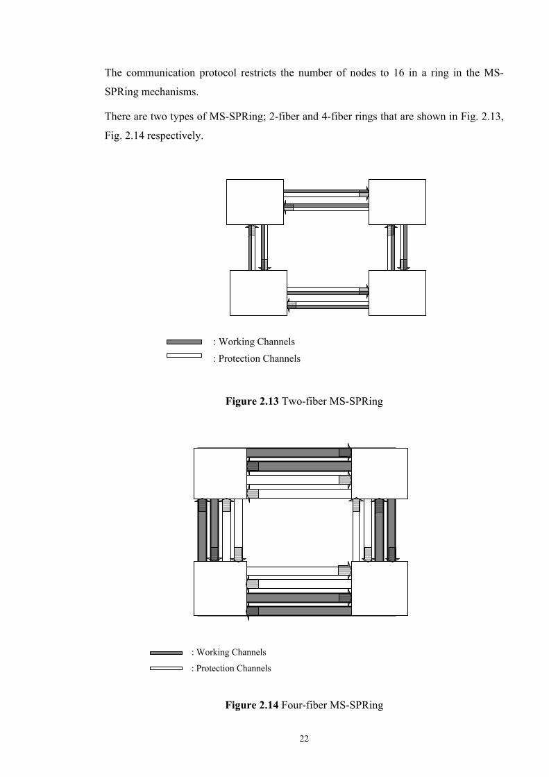
The communication protocol restricts the number of nodes to 16 in a ring in the MS-
SPRing mechanisms.
There are two types of MS-SPRing; 2-fiber and 4-fiber rings that are shown in Fig. 2.13,
Fig. 2.14 respectively.
Figure 2.13 Two-fiber MS-SPRing
Figure 2.14 Four-fiber MS-SPRing
: Working Channels
: Protection Channels
: Working Channels
: Protection Channels

23
ADM 4 ADM 3
ADM 2 ADM 1
: Protection Channels : Working Channels
2-fiber MS-SPRing protection architecture uses half of the capacity of the ring for
working traffic, and reserves the other half of the ring capacity for protection. This
protection mechanism uses both of the fibers to carry working traffic, but half of the
capacity on each fiber is reserved for protection purpose. 2-fiber rings with shared
protection use ring switching for protection purposes.
4-fiber MS-SPRing uses two fibers for working traffic and reserves the other two fibers
for hot stand-by in case of a failure. A 4-fiber MS-SPRing has two types of protection
mechanisms, span switching and ring switching. 4-fiber rings enable the protection
mechanisms of either ring or span switching, but not both of them simultaneously.
Figure 2.15 Two-fiber MS-SPRing Protection
under link failure condition
An example of MS-SPRing protection with two fibers against a single link failure is
given in Figure 2.15. In normal conditions, both channels of the demand 2-4 travel
through 2-1-4. When a failure occurs on the fiber between node 1 and node 2, the
adjacent ADMs to the failure node 1 and node 2 are responsible for protection switching.
In the case of the failure condition, the traffic is looped back to the channels dedicated for

24
protection as illustrated in the Fig.2.15. Since MS-SPRing Protection architecture is used,
the half of the capacity is reserved to handle failures.
In span switching, if an optical fiber cut occurs on a working fiber, the responsible nodes
adjacent to the failed link try to send the traffic to the dedicated protection channels in the
same direction around the ring. Thus, the traffic is routed onto the protection fiber
between the two end nodes of the failed link. If both working and protection channels
breakdown at the same time, the ADM nodes loop the traffic to the reverse direction
around the ring on the reserved protection fibers. Thus, ring switching is the mechanisms
that reroute the traffic along the other part of the ring using the protection fibers available
in the other direction of the ring in case of a link or node failure.
Although most of the deployed networks use 2-fiber MS-SPRing protection mechanism,
some carriers have deployed 4-fiber rings. 4-fiber MS-SPRing can handle more than one
failure in the network. However, management of 4-fiber ring is more complicated than 2-
fiber MS-SPRing because multiple protection mechanisms must be coordinated.
In SNCP ring protection architecture, every demand is duplicated at the origin node and
routed to both ways around the ring, in which a main path along one side of the ring and a
dedicated backup path along the other side of the ring as seen in Fig. 2.16. In the case of a
failure, the receiving node selects the protection path through switching establishing 1:1
selection.
Figure 2.16 SNCP Protection under link failure condition
: Protection Channels : Working Channels

25
In MS-SPRing, the bandwidth is bounded with the largest sum of traffic routed over any
span, also reserving 100% extra capacity for protection; whereas in SNCP, the ring
bandwidth must be at least the sum of all traffic demands in the ring.
If the traffic is more evenly distributed around the ring, MS-SPRing is more capacity
efficient than SNCP rings. Furthermore, it is possible to transmit extra low-priority traffic
on the protection capacity, whereas this is not supported in SNCP rings since the
protection capacity is used for the protection switching operation. The extra traffic
transmission possibility is only available on protection channels under normal conditions,
in case of a failure the low-priority traffic is not considered and will be preempted. There
is no limit on the number of nodes in a SNCP ring, and SNCP rings are easy to
implement because of their simple protection mechanisms.
2 or 4-fibre MS-SPRing has some advantages over SNCP rings whenever traffic sources
and destinations are more evenly distributed around the ring. Furthermore, although it is
possible to support extra low-priority traffic on the protection capacity of MS-Spring
architecture, it is not possible in a SNCP ring network since the protection capacity is
always used for the protection switching operation.
2.4 SDH Ring Design Problem
In the previous sections, we have presented several network architectures and protection
types. The importance of survivability and the layered structures also have been
discussed. In this section we present the problem of SDH ring design and of embedding
the logical rings onto the physical topology.
As we have discussed the layered architecture, there are several layered network
structures. Survivability may be implemented in different layers. In our work, we have
the mesh physical topology with some ADM nodes over this physical topology. The
demand between ADM pairs are also given. SDH ring design problem solves the
following sub-problems:
• Selection of SDH rings to be deployed in the multi-ring architecture, which is
overlaid over the mesh physical topology.
• Routing of demand over the multi-ring network.
• Embedding of SDH rings over the mesh physical topology.

26
We use SDH ring protection for resilience. We have discussed the advantages of ring
networks for protection. A ring provides two diverse paths between any two nodes and
the protection mechanisms work well for any single failure. The survivability in other
layers and multi-layer survivability is not included in this thesis.
The problem we deal with is connecting the given ADM nodes with rings satisfying the
given traffic demands. We decouple the problem into two sub-problems. The first one is
the logical (SDH) ring design. The problem is how to select the SDH rings to be
deployed. The second problem is mapping of these selected rings onto the physical
topology.
In section 2.2, the layered structure was discussed. In our problem, we can divide our
network into two: logical and physical topologies. The physical topology is the network
topology seen by the optical layer. The nodes in this topology correspond to the optical
cross-connects (WSXCs or WIXCs), and two nodes are connected by a link if the OXCs
are connected by an optical fiber link. The logical or virtual topology is the network
topology seen by the higher SDH layer. The nodes in this topology are the nodes of the
higher layer, ADMs or DXCs, and a link corresponds to a lightpath established between
two SDH nodes. The SDH layer is responsible for routing and multiplexing the
connections over the links in the logical topology. This structure can be seen in Figure
2.17.
Optical Fiber Link
OXC
Lightpath
SDH Node A
SDH Node C
SDH Node B
OXC
OXC
OXC
Lightpath
(a)

27
Figure 2.17 Physical and logical topologies for a SDH network
over the DWDM layer
(a) The physical topology (b) The logical topology
We are given the nodes in the logical network and the traffic between different SDH node
pairs. The physical topology, which has a mesh structure, is also given. Given these
inputs, we determine the topology of the logical network, routing of the traffic over this
topology and mapping of this logical topology onto the physical layer. This problem is
known to be a hard problem and there are several heuristic design algorithms in the
literature about designing the logical network and embedding into the physical topology.
A survey of previous works on the design will be discussed in Section 2.5.
In general, the logical topology design problem is the problem of satisfying the traffic
demand requirements and minimizing the cost while ensuring the protection level against
single link or node failures. We assume that there is enough capacity in the physical
network for carrying given demand pairs.
When selecting the SDH rings, we try to minimize the inter-ring traffic. Inter-ring traffic
is the amount of the traffic between two demand nodes belonging to different rings. Inter-
ring traffic requires high cost cross-connect equipments and increase the overall cost and
also the complexity of the network. Digital Cross-Connects are the major components in
the SDH infrastructure and they are used to manage all the transmission facilities in the
central office. DXCs are used to interconnect the SDH rings, and they may also
incorporate ADM functions. To provide the connectivity between rings, DXCs are
connected to ADMs. DXCs automatically cross-connect the traffic ports between
different ADMs belonging different rings. They can handle a large number of ports. The
bigger DXCs with more cross-connect port capabilities result in higher costs. If DXCs do
SDH Node A
SDH Node C
SDH Node B
Lightpath Lightpath
(b)

28
Ring 4
Ring 3
Ring 1 Ring 2
DXC 4
DXC 6
DXC 8
DXC 2
ADM 1
ADM 4-2
ADM 8-2
ADM 8-1
Node-8
ADM 3
ADM 7
ADM 9
ADM 4-1
Node-9 Node-7
Node-1 Node-2 Node-3
Node-4 Node-6
Node-5
DXC
5
ADM 2-1
ADM 6-2
ADM 5-4
ADM 5-3
ADM 5-1
ADM 5-2
ADM 6-1
ADM 2-2
not exist, the inter-ring traffic has to be cross-connected by manual patching in a patch
panel.
When determining the SDH rings, the networks must satisfy two constraints. First, each
ring should satisfy 2-connectivity, i.e. there should exist two physically diverse paths
between any two nodes on the ring. Second, the number of nodes on each ring should not
exceed a maximum node number. Examples of ring selection are illustrated in Figure
2.18.
(a) SDH network with 4 rings

29
Ring 3′
Ring 1′
ADM 2
ADM 1
ADM 6-1
ADM 6-2
Node-8
ADM 3
ADM 4-1
Node-9 Node-7
Node-1 Node-2 Node-3
Node-4 Node-6 Node-5
ADM 5-1
ADM 5-3
DXC 6
DXC 4
ADM 4-2
ADM 8
ADM 7
ADM 9
(b) SDH network with 2 rings

30
Ring 1′′
ADM 2
ADM 1
Node-8
ADM 3
Node-9 Node-7
Node-1 Node-2 Node-3
Node-4 Node-6
Node-5
ADM 5
ADM 6
ADM 4
ADM 8
ADM 7
ADM 9
(c) Unwanted situation, Node-5 is disconnected
Figure 2.18 The SDH ring structures and face merges.
This example summarizes the ring design steps. Figure 2.18 (a) illustrates the network
with four SDH rings. The inter-ring traffic is large and at each hub node DXCs are used
to interconnect SDH rings. To provide the connectivity between rings, DXCs with
different sizes are connected to ADMs according to the amount of inter-ring traffic.
While a smaller DXC is deployed at nodes 1,2,3 and 4 that interconnect two SDH rings
each, a DXC with greater cross-connect capability is deployed at node 5, which
interconnects rings 1, 2, 3 and 4. In order to reduce the network cost, we try to decrease

31
SDH Node B
SDH Node C
SDH Node A
Logical SDH Ring
(a)
the inter-ring traffic, so the cost of DXCs. In Figure 2.18 (b), ring 1 and ring 2 as well as
ring 3 and ring 4 are merged. Thus, there are two new rings, ring 1′ and ring 3′. In this
architecture, node 1 and node 4 have no longer any digital cross-connect equipment
because these nodes belong to only one ring. Also, in node 5, smaller DXC is needed
since the inter-ring traffic is smaller. If two new rings in Figure 2.18 (b) are tried to be
merged, node 5 will no longer be connected to other nodes in the network and the traffic
demands of this node cannot be routed. Thus, this merging step is not allowed and ring 1′′
is not feasible. The 2-connectivity condition guarantees 100% restoration against any
single failure within the network. The second constraint is the node constraint. The total
number of nodes on a ring is upper bounded. This constraint is mainly due to
technological limitations in optical transmission.
Once SDH rings are determined, the second problem is the deployment of selected rings
onto the physical topology. For this mapping, we need to ensure the survivability while
minimizing the network. As we have discussed before, different layers have their own
protection mechanisms, however in our work we assume that only SDH layer protection
is used. An SDH ring provides the survivability in case of one node or link failure, but
one physical link or node failure may result multiple simultaneous failures in logical layer
if there are multiple logical links sharing this physical link. To solve this problem, all
SDH links belonging to one ring have to be mapped onto link and node disjoint lightpaths
in the physical topology.

32
Optical Fiber Link
Lightpath
SDH Node
A
SDH Node
C
SDH Node B
OXC-1
Lightpath
OXC-3
OXC-4
OXC-2
OXC-6 OXC-5
Lightpath
(b)
OXC-2
OXC-5
SDH Node B
SDH Node C
SDH Node A
Logical SDH Ring
(c)
Figure 2.19 An example of mapping a logical ring onto physical topology
(The logical links of ring are mapped onto not physical link disjoint paths)

33
An example of embedding a logical SDH ring onto a physical topology is illustrated in
Figure 2.19. Figure 2.19 (a) shows a logical SDH ring with three nodes. In Figure 2.19
(b), this ring is mapped onto the physical topology. The two logical links between A-B
and B-C belonging to the same SDH ring are mapped onto the same physical link
between OXC-2 and OXC-5. In this case, the failure of the link between OXC-2 and
OXC-5 results in two simultaneous failures on the ring. As illustrated in Figure 2.19 (c),
two logical links are broken at the same time, and the ring protection mechanism does not
work in this case. Therefore, each ring should be mapped onto physically disjoint links.
The same is true for node sharing; the logical links should not pass through the same
node more than once for any ring. Otherwise, multiple failures in logical layer may occur
due a single node failure, and ring protection cannot restore the failed traffic.
2.5 Survey of Previous Work on SDH Ring Design
Since fiber optic cable has a great potential to carry large quantities of data over large
distances, telecommunications networks utilize a SDH/SONET based infrastructure.
Optimality or cost effectivity is the crucial design parameter in telecommunications
networks. There are a large number of network designs for this complex, multi-faced
problem.
The other important criterion for the design problem is network survivability. Thus, the
design algorithm must be capable of generating survivable and cost effective networks.
Ring or multi-ring architectures are generally preferred since they offer high network
survivability in case of a failure and considered as cost effective.
Although the functional operation of a single ring for restoration is simple, the design of
fully restorable networks employing multiple rings is an extremely complex optimization
problem.
Also, the network ring design problem is a complex problem since it consists of several
parts to achieve an optimum solution. The main parts of network ring design are link
capacity assignment, routing and ring determination. The problem consists of sub-
problems such as determining the number of rings, the number of nodes in each ring and
the interconnection among rings. These problems are generally solved with heuristic
methods leading to locally optimal design solutions.

34
There exist several criteria to determine the objective of the ring design problem. In this
section some of the studies on this problem will be discussed.
In the traditional mesh transport networks, determining which of the possible
SONET/SDH rings will be built is the main problem. The objectives can be minimizing
the cost, minimizing the number of rings, minimizing the inter-ring traffic or other
approaches.
There are several approaches on ring design, some of them are SDH/SONET ring design,
and others are optical ring design. In the design algorithms, there exist several network
types: single SDH-layered networks, single WDM-layered networks, and SDH over
WDM transport networks. We summarize the ring design approaches as follows:
An approach of a Genetic Algorithm to the cost-effective network ring design problem is
presented in [10], that the Genetic Algorithm representation encapsulates all aspects of
the problem and solves them simultaneously. Genetic Algorithms work with a population
of solutions and have shown themselves to be efficient at searching large problem spaces
and have been successfully used in a number of engineering problem areas, including
telecommunications network design. Optimal network ring design is divided into three
main parts: routing of all traffic in the network, link capacity assignment and
determination of multi-ring topology of the network. In the ring design, the traffic is
routed using Dijkstra shortest path algorithm and link loadings are computed to determine
link bandwidths and costs. The objective of [10] is to minimize the overall cost of the
network while determining the routes used by all traffic in the network, the link capacities
and the multi-ring topology of the network. The cost term includes the link lengths, link
bandwidths and also a term dependent upon the multi-ring topology of the network.
The ring design problem is described as the SONET Ring Assignment Problem (SRAP)
in [11]. In mathematical formulation, the objective is to minimize the number of rings
such that the constraints limit the total demand on a ring and force that every site is
placed on exactly one ring and connect the rings with a federal ring. There is also another
alternative as k-SRAP that minimizes the traffic on the federal ring which is an effective
approach but more time-consuming. Same as in [10], it is chosen to single out the
objective of minimizing the number of rings to minimize the Digital Cross Connects
costs.
The self-healing ring network design problem is also studied and described several
planning problems of survivability [12]. A formulation of the design of a network

35
composed of multiple interconnected unidirectional Self-Healing Rings is given. The
objective is again to minimize the sum of ADM and inter-ring traffic costs.
SONET ring design, called the Minimum Coverage Connected Rings (MCCR) problem
is represented in [13]. The objective is to select the least expensive set of self-healing
rings such that given traffic demands are all covered. This problem is formulated and
solved using Integer Programming (IP) techniques.
Since the network ring design problem is known to be NP-hard, a lot of heuristic
approaches have been developed to obtain an approximate solution. In recent years, many
metaheuristics such as genetic algorithms, simulated annealing, tabu search have been
used for solving a wide range of combinatorial optimization problems in network design.
A survey of these algorithms can be found in [14].
A tabu search algorithm for self-healing ring network design has been proposed in [15].
The tabu search algorithm is based upon a general iterative search method. The tabu
search method generally uses neighborhood search strategies to search for better solutions
using memory list of history of the recently searched processes for avoiding cycling.
A design of hybrid ring-mesh network in survivable communication network is discussed
in [16]. The problem is to assign each given traffic demand to rings and mesh network. In
this assignment problem, the objective is to minimize the cost of ADM and DCS
equipments using a tabu search solution. But, the algorithm does not generate a node-
disjoint topology, which prohibits its usage against node failures.
Designing ring networks for metropolitan area networks are discussed in [17]. This work
focuses on designing a feasible ring with an objective of maximizing the sum of all
revenues excluding the construction costs for metropolitan area networks. Various
heuristics are applied and a metaheuristic is determined as giving the best results
concerning solution quality.
The ring identification and routing in the logical network are investigated in [18]. To
provide the necessary transport capacity for a given traffic pattern, an optimized
algorithm is presented to embed a mesh of rings network onto an arbitrary network
topology. The objective is minimizing the network cost while also minimizing the inter-
ring distance cost. Three-layer graph model and simulated annealing is used to optimize
the ring configuration in the design process. The general aim is to minimize the ring
configuration and the routing on the virtual network with respect to the given objective
function so that all traffic demands are fulfilled under the constraints, e.g. the capacity per
link. The first and lower layer, called the ring configuration layer, consists of the real

36
fiber links and real node topology. The second layer, called virtual network layer, defines
the connection allocation resulted from the lower layer rings. At this layer, the nodes
belonging to more than one ring are represented with multiple virtual copies, and an
efficient logical topology routing is realized. The ring connection layer is the third layer
defining the connections among the actual rings. In this representation, every ring is
drawn as a node and the edges are constructed between rings if there is a network node
belonging to both rings. The routing between rings is computed using this architecture.
The summaries of ring design approaches above are all about SDH ring network design.
SDH over WDM network design and optical ring design approaches are summarized as
follows:
The cost of laying a new fiber is very high, and DWDM has an advantage because it
offers customers a less expensive way to expand capacity. The usage of DWDM in
metropolitan area networks is discussed in [19]. Metro optical networking is introduced
using optical ADMs (OADMs). Higher transport efficiencies are achieved by eliminating
high-speed TDMs, and reducing the cost of fiber in the network. Optical protection
architectures, especially self-healing optical rings and 1+1 protections are introduced.
The multi-ring optical network design problem is discussed in [8]. The problem is
described as designing minimum-cost transport networks using path-protection and
shared-protection optical rings. Three integer-programming formulations are proposed,
and their features for the multi-ring network design are discussed. They indicated that
these approaches could provide useful solutions to a difficult optimization problem.
SDH-over-WDM network design involving survivability requirement, ring selection,
traffic routing, and overlay ring optimization in order to recover from network failures
are described in [20]. Two key issues are represented for designing. One of them is the
appropriate choice of survivability strategy; the other is the dimensioning of the network.
Three types of survivability architecture are discussed: inter-connected protection rings,
end-to-end path protection and restoration. Since restoration has slower restoration time,
it is not considered. Two types of ring protection strategies are considered: MS-SPRings
and SNCP rings. The MS-SPRings are shown to be less cost-effective than using SNCP
rings in an interconnected ring network. Therefore, in GTS’s transport network, SNCP
rings are selected. Some design concepts for IP-over-WDM networks are provided as
well.
In transport networks, there are two main problems for different transmission
architectures with an objective of minimizing the total network cost. In the first one, the

37
architecture of the transport network is known and the problem is integrating the new
technology, such as DWDM, into the existing SDH infrastructure. The second problem is
designing and dimensioning of SDH rings and mapping these logical rings onto the
existing physical DWDM topology. In both problems, the aim is to obtain a cost effective
network. We focus on the second problem in this thesis.
In the first problem, the integration of WDM technologies into the existing SDH/SONET
transport network, there are several approaches. A heuristic technique based on simulated
annealing was used to optimally design the physical layer in [21]. SDH design, WDM
optical layer design, physical layer design, and global optimization problems are
discussed. The main objective is again minimizing the network equipment and
infrastructure requirements based on the requested protection level. In this design
process, two sub-problems exist. First one is to create an ideal topology for designing the
SDH/SONET layer, based on the network infrastructure cost and offered traffic. In the
second problem, sets of nodes are grouped to form rings with respect to traffic demands.
After the rings are identified, the demands are routed over the rings.
We work on another problem in this thesis: mapping the logical SDH rings onto the
existing physical DWDM topology. There are also some design approaches in the
literature dealing with this problem.
With lower layer network usage, like WDM, the failure of a single link or node may
cause the simultaneous failure of several traffic channels, making impossible to reroute
the failed traffic in higher layers, such as SDH. The “design protection” is represented in
[22] of which aims at making such failure propagations impossible. Protection inside
WDM networks, performed at physical and design levels is discussed. The Disjoint
Alternate Path (DAP) algorithm is presented to maximize the protection.
2.6 Summary of Proposed SDH Ring Design Algorithm
In the previous section, previous work on SDH ring design and related design approaches
are described. The complexity of network design is considered with several parts of the
design process in order to achieve an optimum solution.
In this thesis we assume that the transport network architecture is composed of two
layers. The lower order physical layer contains the fiber topology and WDM nodes. The
higher order logical layer comprises multiple SDH rings. In this layer a path exists
between all demand pairs, and these rings are mapped onto the physical topology.

38
Our work consists of two parts: first one is to determine the SDH rings to satisfy the
given traffic demands ensuring the survivability, and the second part is to map these rings
onto physical topology with an objective of minimizing the network cost.
The first sub-problem aims to minimize the inter-ring traffic since the inter-ring traffic
can be routed by digital cross-connects, which increases the cost substantially. There are
two constraints, one limiting the ring size and second ensuring the connectivity.
The second sub-problem is to map the logical rings onto the physical topology. In this
approach, the logical links of one ring must be mapped onto disjoint paths over the
physical topology. Otherwise, the protection mechanism of SDH rings does not work
properly in case of a single failure.
To address these two problems, we have divided the solution into two parts. First part is
the logical ring design. In the design algorithm, first we obtain a logical topology
interconnecting the closest SDH nodes such that the logical graph is planar. Once the
logical graph is obtained, we construct rings using the faces of the planar graph. To
minimize the inter-ring traffic, each route passes through minimum number of rings.
After all traffic demands are routed, faces are started to be merged such that in the
resulting topology inter-ring traffic is decreased. Faces are merged until there exists no
feasible ring merging that satisfies 2-connectivity and maximum ring size constraints.
The solution for the first sub-problem can be summarized as follows:
1. Obtaining the logical graph: In this part, the problem is to connect geographically
close SDH nodes to each other. The logical graph is obtained such that it is planar.
2. Finding the faces: To find the rings we use faces of the planar logical graph as a
starting solution. After faces are fixed, traffic is routed using a shortest path algorithm.
3. Face merges: In the process of ring selection, the objective is minimizing the network
cost. Minimizing the inter-ring traffic reduces the digital cross-connect costs, which in
turn reduces the overall network cost. Thus, we try to merge faces under the connectivity
and ring size constraints with an objective of minimizing the number of rings and the
resulting inter-ring traffic.
After all feasible face-mergings are completed, the SDH rings are obtained. Next part of
the solution is to deploy these rings onto disjoint physical paths. We formulate the
problem as an integer linear program (ILP). Our objective is to minimize the total
network cost such that the traffic is routed over physically link and node disjoint paths.

39
In the remaining part of this section we summarize other approaches for SDH ring design
in the literature and compare with the design process proposed in this thesis. The self-
healing ring design problem is considered to protect the transmission of demands in a
network in [15]. A modeling approach taking into account ring interactions is proposed,
and a tabu-search-heuristic algorithm is presented. Multiple SHR network design
problems dealing with networks in which nodes can be connected to more than one ring
are considered and the traffic is routed over SHRs such that the inter-ring traffic is
minimized. In the design, each node may be connected to several rings and the resulting
SHRs are only logical structures since it is not guaranteed that a feasible cycle connecting
the nodes of the ring exists.
A tabu search algorithm is proposed for this problem, which based on simple moves such
as adding or removing a single node from a ring. They start with a ring and fill the
residual capacity of that ring without inter-ring traffic. However, to provide some free
capacity in anticipation of the inter-ring traffic, the flow on a ring is limited to a
proportion of its nominal capacity. After the rings are determined and demand nodes are
assigned to the rings, the second sub-problem performs the routing of the resulting inter-
ring traffic verifying the maximum ring capacity constraint. Indeed, once the ADM
connections are chosen, the problem reduces to a minimum cost multi-commodity flow
problem on the auxiliary graph.
This design process does not have a step merging rings in order to minimize the inter-ring
traffic. Instead the rings are pre-determined. Furthermore, mapping of these rings over the
physical layer such that full protection is guaranteed under all single failures is not
considered.
In the SONET Ring Assignment Problem (SRAP) approach presented in [11], an ILP
formulation, which has an objective of minimizing the number of rings, is given. The
constraints limit the total demand on a ring to a bandwidth and limit the capacity of a
federal ring, which connects all rings together. This special ring carries all the traffic
between sites on different rings. There is also an alternative solution: instead of
minimizing the number of rings the traffic on the federal ring is minimized.
In our design algorithm, there is no assumption of a federal ring, and we minimize the
inter-ring traffic. To minimize the number of rings can result in a similar solution since
there is smaller amount of inter-ring traffic in a network with larger rings.
After logical ring design is completed, the second important issue is the mapping of these
rings onto the physical topology. The failure of a single optical link or node in a WDM
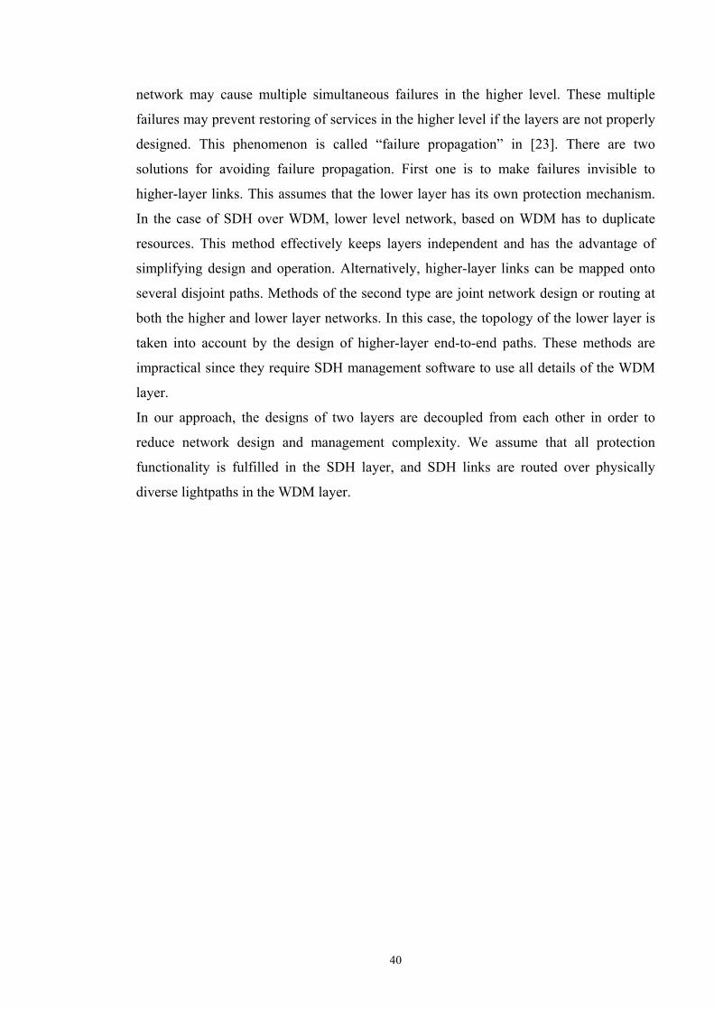
40
network may cause multiple simultaneous failures in the higher level. These multiple
failures may prevent restoring of services in the higher level if the layers are not properly
designed. This phenomenon is called “failure propagation” in [23]. There are two
solutions for avoiding failure propagation. First one is to make failures invisible to
higher-layer links. This assumes that the lower layer has its own protection mechanism.
In the case of SDH over WDM, lower level network, based on WDM has to duplicate
resources. This method effectively keeps layers independent and has the advantage of
simplifying design and operation. Alternatively, higher-layer links can be mapped onto
several disjoint paths. Methods of the second type are joint network design or routing at
both the higher and lower layer networks. In this case, the topology of the lower layer is
taken into account by the design of higher-layer end-to-end paths. These methods are
impractical since they require SDH management software to use all details of the WDM
layer.
In our approach, the designs of two layers are decoupled from each other in order to
reduce network design and management complexity. We assume that all protection
functionality is fulfilled in the SDH layer, and SDH links are routed over physically
diverse lightpaths in the WDM layer.

41
Chapter 3
SDH RING DESIGN PROBLEM
In this chapter we present the problem of selecting the SDH rings to be deployed over the
physical topology. We are given the physical topology, locations of SDH ADM nodes
and traffic demands between these nodes. The problem is to map this traffic onto physical
topology in order to obtain a logical topology comprising multiple rings interconnecting
SDH nodes.
The logical topology is the network topology seen by the higher SDH layer. The higher
layer SDH network is also called the logical or virtual topology. The nodes in the logical
topology are the nodes of the higher layer, ADMs or DXCs, and a logical link
corresponds to a lightpath established between two SDH nodes. The SDH layer is
responsible for routing and multiplexing the connections over the links in the logical
topology.
An example of SDH over DWDM topology consisting of OXCs at the lower layer,
ADMs and DXCs at the higher layer is seen in Figure 3.1. The logical topology is
indicated by dashed lines and physical topology is indicated by straight lines.

42
ADM ADM ADM ADM
ADM ADM ADM ADM
OXC
OXC
OXC
OXC OXC
OXC
DXC
DXC
Optical fiber
: Physical topology : Logical topology
Figure 3.1 A SDH network over the optical (DWDM) layer
Our main objective is to minimize the inter-ring traffic, which is the set of demands
between two SDH nodes belonging to different rings. Inter-ring traffic requires high cost
cross-connect equipments and increase the overall cost and also the complexity of the
network as shown by the example in Figure 3.2. In this example, there are five seperate
SDH rings in the network. This situation requires DXC equipments at the interconnection
nodes of network for carrying the inter-ring traffic between nodes belonging to different
rings. Network management becomes more complex when there are several DXCs at the
intermediate nodes between rings.

43
ADM
ADM
ADM
ADM
ADM
ADM
ADM
ADM
ADM
ADM
ADM
ADM
ADM
ADM
ADM
ADM DXC
DXC
ADM
ADM
ADM
ADM
DXC
Figure 3.2 A multi-ring SDH topology with several inter-ring traffic
3.1 Logical Topology
As we have discussed in previous sections, the network can be represented by two layers.
Higher layer is the SDH logical layer with multi-ring SDH topology and the lower layer
is the physical layer composed of physical links with fiber optic cables and nodes with
DWDM optical cross-connects. The physical topology is represented by a mesh network.
ADMs are located at some of these nodes and traffic demands between these ADM nodes
are also given.
First, we want to determine which SDH nodes can be connected to each other using
lightpaths. The idea we use is to connect the ADM nodes with others starting from the
closest ADMs. The first step is to find the constrained shortest paths between all ADMs
in the physical topology such that there are no other ADMs between two SDH nodes. If
there exists such a path, these two ADMs are connected in the logical topology with a

44
link. The weight of the link is equal to the number of hops on the path connecting the two
ADMs in the physical topology. If there is no such path, a link is not placed between
these ADMs in the logical topology.
Once the logical topology is obtained, we find a maximal sub-graph of the logical graph
such that this graph is planar and no other edge in the logical topology can be added. A
planar graph is a graph that its edges do not intersect except their common end vertices
[24]. It means that there exists an ADM node at the junction point of two links. The
reason that we require a planar logical graph is that we use faces of a planar graph in
order to construct rings.
In order to obtain the planar logical graph, we first sort all links in the logical topology in
an ascending order. Starting from the shortest link in the list, we try to include each link
in the logical topology such that the graph is planar. We continue this procedure until all
links are considered. The reason that shorter links are considered first is that closer SDH
nodes are better candidates for placing on the same ring.
The planar logical graph corresponding to the physical topology in Figure 3.3 is shown in
Figure 3.4. The link weights denote the number of hops on the path connecting two nodes
in the physical topology. The links that hinder planarity are not included in the logical
graph.
Figure 3.3 A physical topology with OXC and ADM nodes
: Node with OXC and SDH ADM
1 2 3 4
5 6
9 10
7 8
11 12
: Node with only OXC
: Physical Link with optical fiber

45
ADM1
ADM2
ADM 3
ADM 4
ADM 5
ADM6
ADM 9
ADM 10
ADM 7
ADM 8
ADM 11
ADM 12
1
1
1
1
1
1 2
2
2
2
2
2 2
2 2
2 2
2
2
2
2
2
2
2
Figure 3.4 Planar logical graph with link weights
Next, we find the faces of the planar logical graph. A face is the cycle bounded by the
edges of a planar graph that forms a ring. Every connected planar graph can be
decomposed into faces. These faces are used as the basis for rings in the network. The
greedy heuristic algorithm proposed in this thesis uses the faces of the logical graph as
the starting solution. In Figure 3.5, the faces of a planar mesh network are shown.
In graph theory, there exist several algorithms for finding the faces of a planar graph [25].
To determine a face, starting from one node, the edges have to be followed by the
clockwise or counter-clockwise direction. The procedure is followed until the first node is
reached [18].

46
Figure 3.5 The constructed faces of a planar mesh network
The links belonging to a face should be 2-connected. The number of faces of a planar
graph G=(V, E) is given by the Euler Formula [26],
F=E-V+2
where F is the number of faces, E is the number of edges and V is the number of
nodes in G.
3.2 Greedy Heuristic Algorithm for Ring Selection
The problem of multi-ring network design is a complex optimization problem to be
solved. Heuristic span elimination strategies for reducing the topology were discussed for
the ring coverage problem [27]. An important point is not selecting the wrong link to be
eliminated. If this is done, inter-ring routing costs increase due to excessive increase in

47
routing with respect to the shortest path. Our algorithm for ring merging is based on
simple moves such as removing a single link from the multi-ring topology.
Inter-ring traffic includes all demands between nodes that belong to different rings. Since
the cost of a ring depends heavily on the cost of digital cross-connects and the inter-ring
traffic defines the size of DXCs, the objective in minimizing the inter-ring traffic is to
reduce the cost of DXCs. To minimize the inter-ring traffic we merge adjacent rings
using a face-merging algorithm. By removing the link shared by two adjacent faces, we
combine two rings. Since there is a larger ring containing both rings, the inter-ring traffic
between these two rings is eliminated.
3.2.1 Face Merging
Given the faces of the planar logical topology and the demands between SDH nodes, the
first step in ring design algorithm is to fix the routing such that each route passes through
minimum number of rings. The routing algorithm for achieving minimum inter-ring
traffic can be described as follows:
For each s-d demand pair,
1. Calculate k-shortest paths between s and d.
2. For each path, find the path traversing minimum number of rings among the
k-shortest path.
An example of starting point at route selection is shown in Figure 3.6.

48
l - 4 Node B
Node A
l - 5
l - 1 F1
F2 F3
: 1st shortest path between Node A and Node B
l - 2
l - 3
l - 6
l - 7
: 2nd shortest path between Node A and Node B
Figure 3.6 An example of routing in a multi-face topology
In the example, there is a network with three faces: F1, F2 and F3. Using k-shortest path
algorithm, the 1st shortest path between Node A and Node B is found as l - 1, l - 2, l - 3,
and l - 4. The 2nd shortest path is given by l - 1, l - 5, l - 6, and l - 7. Since the path traversing
minimum number of rings is required between nodes A and B, we construct a trellis
graph for finding the path with the minimum number of rings for both paths as shown in
Figure 3.7 and Figure 3.8.

49
F3
F3
F3
F3
F3
F3
1
1
1
1
1
1
F3
1
1
F2
F2
F2
F2
F2
F2
F2
F2 F3
0
0
0
0
0
0
0
0
F2
F2
F2
F2
1
1
1
0
F1
F1
1
1
Node A
Node B l 1 l 2 l 3 l 4
Node A
3 3 3 3 3 3 3 3
Node B
Figure 3.7 Minimum number of rings path for 1st shortest path
Since some links may belong to more than one face, we determine the routing which
achieves minimum number of ring crossings.
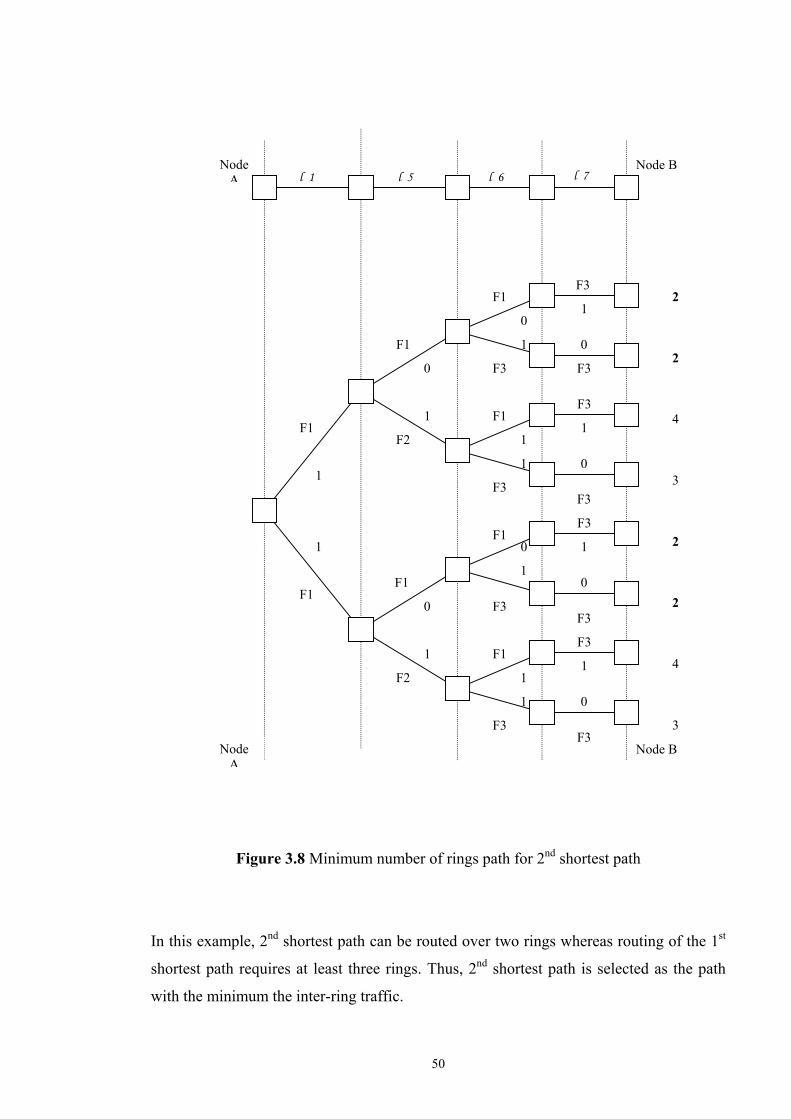
50
F3
F3
F3
F3
F3
F3
1
0
1
0
1
0
F3
1
0
F1
F1
F1
F1
F3
F3
F3
F3 F3
1
1
0
1
0
1
1
1
F1
F1
F2
F2
1
0
1
0
F1
F1
1
1
Node A
Node B l 1 l 5 l 6 l 7
Node A
2 2 4 3 2 2 4 3
Node B
Figure 3.8 Minimum number of rings path for 2nd shortest path
In this example, 2nd shortest path can be routed over two rings whereas routing of the 1st
shortest path requires at least three rings. Thus, 2nd shortest path is selected as the path
with the minimum the inter-ring traffic.

51
l - 7
l - 2
l - 6
l - 1
l - 3 l - 5 l - 4
F1 F2 F3
F5 F6 F4
l - 1 l - 2
l - 3 l - 5
l - 6 l - 7
l - 4
F 6
F 1
F 4 F 5
F 3 F 2
(a)
(b)
After the route for each demand is fixed for a given set of rings, we start to merge the
rings in order to minimize the inter-ring traffic.
The face adjacency graph is obtained by assigning a node corresponding to each face and
by connecting the faces that share a link in the logical topology with a link in the face
adjacency graph. An example of a planar logical topology and the corresponding face
adjacency graph is given in Figure 3.9.
Figure 3.9 An example of a network topology (a) A planar logical graph with faces
(b) Face adjacency graph
After the all traffic demands are routed and the face adjacency graph is constructed, we
start to merge adjacent faces. Face merging is combining two adjacent faces by
eliminating the shared link.

52
F1 F2
N1
F1′
N1
In our greedy heuristic algorithm, we look all feasible face mergings, and choose two
faces that give minimum inter-ring traffic as the rings to be merged. In the face-merging
algorithm, there are two constraints that determine feasibility of each possible face
merging. The first one is the node constraint. The number of nodes belonging to the new
face after merging must be smaller than Nmax. If the network becomes too large, there
may be inefficient routing in this network. The node size constraint is dictated by the
limitations in the SDH technology. The second constraint is the 2-connectivity. Two
faces can only be merged if the resulting graph satisfies 2-connectivity. Faces can be
merged if they share at least and at most one link. If they share two links, they cannot be
merged because the resulting graph may not be 2-connected as shown in the example
given in Figure 3.10.
Figure 3.10 An example of disconnected graph after face merging
In this example, face 1 and face 2 are adjacent faces and shares two links. If we merge
these two faces, the node N1 will be disconnected. In this case, it is not possible to
transmit any traffic to or from N1. 2-connectivity is also a crucial constraint for
protection purpose. If a network is 2-connected, there are at least two disjoint paths
between any two nodes, and the network is resilient to any single failure.

53
ORIGINAL : SDH Nodes
We continue enlarging the faces until there exists no feasible face merging. After each
face-merging step, the routing algorithm is used to fix the new paths and the face
adjacency graph is updated accordingly.
3.3 Numerical Results
In this section, we present the design of logical (SDH) rings of a given network topology
using the proposed heuristic algorithm. Our greedy heuristic algorithm is applied to three
different network topologies. The topologies are given in Figures 3.11 - 3.13 respectively.
The 32-node mesh topology is composed of optical cross-connects at all nodes and SDH
ADMs and DXCs at 13-nodes for all three examples. The weights of the links in the
network are the real distances between nodes. For the 13-node SDH logical network, 3
different node size constraints were used in the merging process. The heuristic algorithm
is implemented on Microsoft Visual C++ 6.0.
The logical topologies obtained by the algorithm are shown in Figures 3.14 - 3.16.
Figure 3.11 The first example: physical topology with 32-nodes

54
ORIGINAL : SDH Nodes
ORIGINAL : SDH Nodes
Figure 3.12 The second example: physical topology with 32-nodes
Figure 3.13 The third example: physical topology with 32-nodes

55
BEFORE MERGING
BEFORE MERGING
Figure 3.14 Logical Topology obtained for 13-nodes SDH network of the first example
Figure 3.15 Logical Topology obtained for 13-nodes SDH network of the second
example

56
R3 R1 R2
R4
R5
R6
R7
AFTER MERGING Nmax=6 (a)
BEFORE MERGING
Figure 3.16 Logical Topology obtained for 13-nodes SDH network of the third example
After the logical topology is obtained, rings are merged to minimize the inter-ring traffic
as shown in Figures 3.17 - 3.19. In this process, the maximum node number constraint is
used for the heuristic merging algorithm.

57
R4 R3 R1 R2
R5
R6
R7
AFTER MERGING Nmax=5
R8
(b)
R11 R7
R6
R5
R2
R4
R3
R1
AFTER MERGING Nmax=4
R8
R9
R10
R12
(c)
Figure 3.17 Ring Merges for the first example (a) Nmax=6, (b) Nmax=5, (c) Nmax=4

58
AFTER MERGING Nmax=6 (a)
R7
R1
R2
R3
R4
R5
R6
R5
AFTER MERGING Nmax=5 (b)
R7
R1
R2
R3
R4
R8
R6

59
R2
Figure 3.18 Ring Merges for the second example (a) Nmax=6, (b) Nmax=5,
(c) Nmax=4
R11
R10
R1
AFTER MERGING Nmax=4 (c)
R7
R2 R3
R4
R5
R6 R8
R9
R1
R7
R3
R4
R5
R6
AFTER MERGING Nmax=6
(a)

60
R2 R7
R4
R5
R6
R8
R2
R7
R4
R5
R6 R8
R9 R10
R11
R12
Figure 3.19 Ring Merges for the third example (a) Nmax=6, (b) Nmax=5,
(c) Nmax=4
AFTER MERGING Nmax=5
(b)
AFTER MERGING Nmax=4
(c)
R1
R3
R1
R3

61
As maximum node size constraint decreases, total number of rings increases. The inter-
ring traffic before and after ring mergings for each node size is given in Table 3.1.
NODE
NUMBER
INTER-RING
TRAFFIC
BEFORE
MERGING
INTER-RING
TRAFFIC
AFTER
MERGING
INTER-RING
MINIMIZATION
RATES
6 30 24 20%
5 30 25 16,67% FIRST
EXAMPLE 4 30 28 6,67%
6 31 20 35,48%
5 31 23 25,8% SECOND
EXAMPLE 4 31 27 12,9%
6 26 15 42,31%
5 26 20 23,08% THIRD
EXAMPLE 4 26 24 7,69%
AVERAGE 21,18%
Table 3.1 Inter-ring traffic changes for a demand set for different size constraints
As shown in Table 3.1, inter-ring traffic is decreased by about 7-42% after the ring
mergings. The average reduction in the inter-ring traffic is about 21,18%, taken over all
examples. After logical topology is obtained, the next step is to map these logical rings onto given
physical topology. In the next chapter we discuss how SDH rings can be mapped onto the
optical mesh topology.

62
Chapter 4
EMBEDDING IN A PHYSICAL
TOPOLOGY PROBLEM
Since today’s telecommunications industry requires high-speed and high-capacity
transport networks, optical fibers are very popular for the large bandwidth supplement.
DWDM allows multiplexing of many wavelengths onto a single fiber, so it is the simplest
way to expand the capacity of the network. The optical layer with DWDM nodes
provides the lightpaths to the higher SDH layer. These lightpaths can currently carry bit-
rates as high as 10 Gb/s, and 40 Gb/s systems are under development.
Different layers have their own protection mechanisms. In our design model, the higher-
layer protection is selected for the advantages of SDH ring protection. The design process
for a network to survive all single link and node failures is a realistic scenario, because
the multiple link or node failures are not often the case in practice. Thus, the ring
protection topology is designed to handle only one failure at any time and reserves the
capacity for rerouting all interrupted traffic.
Even if optical layer protection and restoration is not used in our design, an important
point is taken into account. In the networks with DWDM equipments, if different logical
links use the same physical resources, the failure of a node or physical link may cause
more than one failure in the higher layer, making it impossible to restore the affected
traffic in the SDH layer. To address this problem, we aim to map each logical ring onto
physical links and nodes such that no two logical links share the same resources in the
physical layer. This is accomplished by routing each logical link on an SDH ring over a
lightpath, which is link and node disjoint from all other lightpaths forming the SDH ring.

63
In this chapter, we present an algorithm of embedding the logical rings onto the physical
topology under the link disjoint and node disjoint paths constraints. The objective of the
algorithm is to minimize the overall fiber cost in the physical layer.
4.1 MILP Formulation
A Mixed Integer Linear Programming (MILP) formulation is developed for the ring-
embedding problem. The complete problem can be divided into two sub-problems. The
first problem is to determine the order in which SDH nodes belonging to the same ring
are connected to each other. Once the logical links on the ring are fixed, these links are
mapped onto the physical topology in the second part. Link and node disjoint paths are
used in this part in order to guarantee correct operation of the SDH ring protection. The
objective of the MILP formulation is to minimize the fiber cost of the physical topology.
This cost is calculated by the total length of all links used by the link disjoint flows.
To formulate the problem in mathematical terms, we introduce a number of definitions.
Suppose the logical network topology is represented by a directed graph G=(V, E), where
V is the set of SDH nodes in the logical topology and E is the set of edges. The decision
variables are defined as follows:
1 if there exists a logical link from SDH node p to q i.e., (p, q)∈E
0 otherwise ypq
=
1 if there exists flow on logical link (p, q)∈E resulting from traffic
carried between SDH nodes r and s,
0 otherwise
zrs
pq=

64
Suppose the physical network topology is represented by a directed graph G′=(V′, E′),
where V′ is the set of OXC nodes in the physical topology and E′ is the set of edges. dnm
is the length of the physical link, where (n, m)∈E′. The decision variable xpq
nm is defined
as follows:
Objective:
Minimize ∑ ∑∈E),( ),(mn qp
xpq
nm. dnm
Subject to:
Cycle constraint:
Total flow on a logical link:
ypq
+ yqp
≤ 1 ∀ (p, q) ∈E (4.1)
∑≠ pq
ypq
= 1 ∀ p ∈V (4.2)
∑≠ pq
yqp
= 1 ∀ p ∈V (4.3)
zrs
pq ≤ y
pq ∀ (p, q), ∀ (r, s) (4.4)
1 if there exists flow on physical link (n, m)∈E′ resulting from the
flow on logical link (p, q)∈E,
0 otherwise xpq
nm=

65
Flow conservation at each SDH node:
Physical Link Disjoint Paths Constraint:
Node Disjoint Paths Constraint:
Flow conservation at each physical node:
Integer Constraints:
ypq
, zrs
pq ∈ {0, 1} ∀ (p, q)∈E
xpq
nm∈ {0, 1} ∀ (n, m)∈E′
1 if p = r,
∑≠ pq
zrs
pq- ∑
≠ pqzrs
qp= -1 if p = s, ∀ p ∈V, ∀ (r, s) (4.5)
0 otherwise,
∑),( qp
( xpq
nm+ xpq
mn) ≤ 1 ∀ (n, m)∈E′ (4.6)
ypq
if n= p,
∑′∈E
mm) (n,
xpq
nm- ∑
′∈Em
m) (n,
xpq
mn= - y
pq if n = q, ∀ n ∈V′ , ∀ (p, q) (4.8)
0 otherwise
∑′∈E
mm) (n,
∑),( qp
xpq
nm= 1 ∀ n ∈V′ (4.7)

66
Ring 1 Ring 2
: A physical node with an ADM
: A physical node without an ADM
: Optical fiber links
The objective of the formulation is to minimize the total fiber cost in the network, which
is the sum of all physical link lengths used by deployed logical rings. Constraint (4.1)
guarantees that two logical links between the same logical nodes do not form a cycle.
Constraints (4.2) and (4.3) express that; for any node on a ring, both the in-degree and
out-degrees are 1. Constraint (4.4) indicates that if there is no SDH logical link between p
and q, i.e., ypq
=0, it is not possible to have flow between p and q carrying the demand
between nodes r and s. Constraint (4.5) verifies the flow conservation at each SDH node
for logical topology such that each demand is routed from its source to its destination.
Constraint (4.6) implies that each logical link on a ring maps onto physical link disjoint
paths. Constraint (4.7) implies that mapping is done onto node disjoint paths. Constraint
(4.8) states the flow conservation at each node for the physical topology. This algorithm
is implemented separately for all rings in the network.
4.2 Post Processing
After mapping of each logical ring onto the physical topology is completed, it is possible
to have some redundant rings. In these situations, we apply a post-processing step to
eliminate these rings. These situations can be summarized as follows:
1. If we have a ring, which is a subset of another ring, this can be eliminated. An
example is shown in Figure 4.1. In this example, Ring 2 is a subset of Ring 1 and the
nodes of Ring 2 are all included in Ring 1. Thus, Ring 2 is redundant and it can be
eliminated.
Figure 4.1 First example of post-processing

67
Ring 1 Ring 2
: A physical node with an ADM
: A physical node without ADM
: Optical fiber links
Ring 1 Ring 2
: A physical node with an ADM
: A physical node without ADM
: Optical fiber links
2. If we have a ring, which is mapped onto the same physical links of another ring,
this can also be eliminated. An example is shown in Figure 4.2. In this example, Ring 2 is
same as Ring 1 and Ring 2 is redundant and it can be eliminated.
Figure 4.2 Second example of post-processing
3. If two rings are mapped onto the physical topology such that they both span the
same SDH nodes, one of them can be eliminated as seen in Figure 4.3.
Figure 4.3 Third example of post-processing

68
(b) R2 (a) R1
(d) R4 (c) R3
We continue eliminating the rings until there exists no redundant ring. After the post-
processing step, we obtain the solution of the SDH ring design problem.
4.3 Numerical Results
In this section, we represent the mapping of the logical rings obtained in Section 3.3.
Using the MILP formulation, each SDH ring is mapped onto link and node disjoint
lightpaths. The MILP formulation is implemented on GAMS and CPLEX commercial
optimization software packages. The SDH rings shown in Figures 3.17 - 3.19 are mapped
onto the 32-node physical topology. The results of three examples are shown in Figures
4.4 - 4.12 for different size constraints.

69
(e) R5 (f) R6
(g) R7
(a) R1 (b) R2
Figure 4.4 Mapping of logical rings of first example (Nmax=6)

70
(b) R2 (a) R1
(c) R3 (d) R4
(e) R5 (f) R6
(g) R7 (h) R8
Figure 4.5 Mapping of logical rings of first example (Nmax=5)

71
(d) R4 (c) R3
(e) R5 (f) R6
(j) R10 (i) R9
(g) R7 (h) R8

72
(a) R1 (b) R2
(c) R3 (d) R4
(e) R5 (f) R6
(k) R11 (l) R12
Figure 4.6 Mapping of logical rings of first example (Nmax=4)

73
(g) R7
(c) R3 (d) R4
(a) R1 (b) R2
(e) R5 (f) R6
Figure 4.7 Mapping of logical rings of second example (Nmax=6)

74
(a) R1 (b) R2
(e) R5 (f) R6
(c) R3 (d ) R4
(g) R7 (h) R8
Figure 4.8 Mapping of logical rings of second example (Nmax=5)

75
(a) R1 (b) R2
(g) R7 (h) R8
(i ) R9 ( j) R10
(k) R11
Figure 4.9 Mapping of logical rings of second example (Nmax=4)

76
(c) R3 (d) R4
(e) R5 (f) R6
(g) R7
(a) R1 (b) R2
Figure 4.10 Mapping of logical rings of third example (Nmax=6)

77
(c) R3 (d) R4
(e) R5 (f) R6
(g) R7 (h) R8
(a) R1 (b) R2
Figure 4.11 Mapping of logical rings of third example (Nmax=5)

78
(c) R3 (d) R4
(e) R5 (f) R6
(g) R7 (h) R8
(i) R9 (j) R10

79
(l) R12 (k) R11
Figure 4.12 Mapping of logical rings of third example (Nmax=4)
After all rings are mapped onto the physical topology, some rings are eliminated by the
post-processing algorithms. After all redundant rings are eliminated, the remaining rings
and their costs are shown in Table 4.1. In the numerical examples, post-processing
decreases the total cost at some rates for different node constraints.
If we compare the total fiber costs of the network after post-processing, as maximum
node number of the ring increases, total fiber cost decreases as expected which is shown
in Table 4.1. After post-processing is applied to the solutions, the fibers cost is reduced
by about 4-33 % for the 32-node network. The average fiber cost reduction after post-
processing is about 12,92% over all examples.

80
1st Example 2nd Example 3rd Example
Nmax=6 Nmax=6 Nmax=6 R1 2.686 R1 3.672 R1 3.096 R2 2.413 R2 2.695 R2 2.312 R3 1.561 R3 2.737 R3 2.856 R4 1.367 R4 1.496 R4 2.317 R5 1.377 R5 1.653 R5 1.316 R6 441 R6 796 R6 1.717 R7 541 R7 1.206 R7 1.882 TOTAL 10.386 TOTAL 14.255 TOTAL 15.496
ELIMINATED 441 ELIMINATED 4.697 ELIMINATED 1.316 4,25% 32,95% 8,50%
Nmax=5 Nmax=5 Nmax=5 R1 2.686 R1 3.444 R1 3.096 R2 2.413 R2 2.695 R2 2.312 R3 1.561 R3 2.537 R3 2.455 R4 826 R4 2.099 R4 2.081 R5 1.185 R5 1.427 R5 2.074 R6 1.021 R6 1.329 R6 1.316 R7 1.001 R7 1.206 R7 1.989 R8 1.010 R8 1.653 R8 1.717 TOTAL 11.703 TOTAL 16.390 TOTAL 17.040
ELIMINATED 826 ELIMINATED 1.206 ELIMINATED 1.316 7,06% 7,36% 7,72%
Nmax=4 Nmax=4 Nmax=4 R1 2.637 R1 3.434 R1 2.255 R2 2.408 R2 2.147 R2 2.147 R3 2.306 R3 2.164 R3 2.312 R4 1.854 R4 1.932 R4 2.306 R5 1.022 R5 1.300 R5 1.558 R6 1.110 R6 1.979 R6 1.691 R7 1.063 R7 1.248 R7 2.074 R8 1.376 R8 1.329 R8 1.063 R9 1.017 R9 796 R9 1.316 R10 1.001 R10 1.653 R10 620 R11 441 R11 1.206 R11 1.882 R12 541 R12 1.538 TOTAL 16.776 TOTAL 19.188 TOTAL 20.762
ELIMINATED 3.769 ELIMINATED 2.002 ELIMINATED 2.767 22,47% 10,43% 13,33%
Table 4.1 Fiber costs of mapped SDH Rings before and after post processing
We also compare the average shortest paths for the networks before merging and after
post-processing. After post-processing, the average shortest path distance increases by

81
about 1-17 % of the original mesh network as shown in Table 4.2. The average increase
of the average shortest path length taken over all examples is about 3,66%.
These numerical results show that additional fiber cost due to routing over a multi-ring
architecture mapped over a mesh topology is reasonably small. This additional cost is
compensated by the larger reduction in DXC costs due to smaller inter-ring traffic after
ring-mergings as shown in Section 3.3. Furthermore, the reduction in the inter-ring traffic
also decreases the network management complexity.
Over the
physical mesh
topology
Over the multi-ring topology
after ring mappings
1st Example Nmax=6 Nmax=5 Nmax=4
Average Shortest
Paths 1456,08 1473,62 1482,35 1506,53
Increase with
respect to mesh
topology
1,21% 1,80% 3,47%
2nd Example Nmax=6 Nmax=5 Nmax=4
Average Shortest
Paths 1528,50 1604,60 1543,24 1791,69
Increase with
respect to mesh
topology
4,98% 0,96% 17,22%
3rd Example Nmax=6 Nmax=5 Nmax=4
Average Shortest
Paths 1509,60 1514,87 1529,85 1529,92
Increase with
respect to mesh
topology
0,35% 1,34% 1,35%
Table 4.2 Average shortest path comparisons for different maximum node number of
three examples

82
Chapter 5 CONCLUSION
The evolution of the telecommunication networks and enormous growth in data traffic
increase the importance of the network protection design. Telecom network operators
strive to deploy their networks such that it is cost-effective and resilient against failures.
Among several technologies, SDH and WDM networks play an important role. Both
networks can be used independently or multi-layer solutions can be used for obtaining
solutions with better performance.
In this thesis, we consider the two-layered network design problem for the SDH over
WDM topology. Since SDH ring networks are widely installed currently and they have
several advantages, in this thesis we study the SDH over WDM network architecture such
that all resilience functions are fulfilled by SDH ring protection. Design of SDH rings
design has been studied extensively in the literature, but the combination of ring design
and embedding of rings onto the mesh optical topology has not been addressed before.
We decouple the overall network design process into two design problems: SDH ring
selection and mapping of these rings onto the physical topology. Both problems are
studied as optimization problems. For the SDH ring selection problem, we present a
greedy heuristic algorithm based on minimization of the inter-ring traffic in order to
reduce the cost and complexity of digital cross-connects. There are two limitations on the
greedy heuristic algorithm: ring size and 2-connectivity. For the embedding of the logical
rings onto the physical topology, we introduce a MILP formulation based on link and

83
node disjoint mapping of each ring in order to guarantee proper operation of SDH
protection against all single link or node failures.
We have tested the proposed ring selection algorithm with different network topologies
and we obtained the cost reductions at different steps on the network. After all ring
mergings are completed, the average inter-ring traffic is reduced by about 21,18%
compared to the initial solution where the average is taken over all examples. Also,
network management complexity is reduced by the minimization of the inter-ring traffic.
Once all rings are selected we mapped these rings onto the mesh optical topology using
the proposed MILP formulation, and then we applied the post-processing algorithm in
order to eliminate redundant rings. The average fiber cost reduction after post-processing
is about 12,92% taken over all examples. The proposed mapping algorithm generates
cost-effective and resilient multi-ring SDH networks.
We have also computed the increase in the average path length for the resulting multi-
ring topology and compared it with the average path length over the optical mesh
network. Our results show that the average path length increase due to longer paths in the
multi-ring topology is only 3,66%, where the average is taken over all examples. This
quantitative result shows that the multi-ring architecture overlaid over an optical mesh
topology increases the average shortest path length at a small amount. Based on these
results, we believe that the architecture of SDH rings over a mesh optical network can be
used for efficient design of resilient networks.
The network design process proposed in this thesis for SDH over WDM networks can be
used to improve the efficiency and cost of the transport networks used by Telecom
operators. Future studies can be focused on developing new heuristic algorithms and
MILP formulations that result in lower network costs. Developing an algorithm for
designing a cost-effective network in which SDH protection and WDM restoration are
used jointly against failures is also an important research problem.

84
Bibliography [1] Daniel Y. Al-Salameh, Mohammed T. Fatehi, William J. Gartner, Stan Lumish,
Bruce L. Nelson, and Kamal K. Raychaudhuri, “Optical Networking”, Bell Labs
Technical Journal, pp.39-61, January-March 1998.
[2] Yasuhiro Miyao, Hiroyuki Saito, “Optimal Design and Evaluation of Survivable
WDM Transport Networks”, IEEE Journal on Selected Areas In Communications,
Vol.16, No.7, pp.1190-1198, September 1998.
[3] F-X. Ollivier, C. Zugno, S.Thompson, “Evolution of high speed DWDM backbone
networks”, Alcatel Telecommunications Review, pp.181-193, 3rd Quarter 2000.
[4] Wayne D. Grover, “Network Survivability: A Crucial Issue for the Information
Society”, IEEE Canadian Review, pp16-21, Summer 1997.
[5] Tsong-Ho Wu, “Emerging Technologies for Fiber Network Survivability”, IEEE
Communications Magazine, vol.33, no.2, pp.58-74, February 1995.
[6] Ornan Gerstel, Rajiv Ramaswami, Xros, “Optical Layer Survivability: A Services
Perspective”, IEEE Communications Magazine, pp.104-113, March 2000.
[7] R. Ramaswami, K. N. Sivarajan, Optical Networks - A Practical Perspective, Morgan
Kaufmann Publishers, Inc., San Francisco, California, 1998.

85
[8] G.D. Morley, W.D. Grover, "Current Approaches in the Design of Ring-based Optical
Networks," Proc. (CD-ROM) IEEE Can. Conf. Electrical & Comp. Eng. (CCECE’99),
Edmonton, pp.220-225, May 9-12, 1999.
[9] António Jaime Ramos CPRM- Marconi, “Optical Network Architectures: Routing
and Protection”, OADM Workshop, 23-24 April 1998.
[10] White, T., Mann, J., and Smith G.D., “Genetic Algorithms and Network Ring
Design”, Annals of Operational Research 86, pp. 347-371, 1999.
[11] Olivier Goldschmidt, Alexandre Laugier and Eli V. Olinick, “SONET/SDH Ring
Assignment with Capacity Constraints”, Technical Report 01-EMIS-05,
pp.104-119, September 26, 2001 .
[12] Soriano P., Wynants C., Seguin R., Labbe M., Gendreau M., and Fortz B., Design
and dimensioning of survivable SDH networks, Chapter 9 in Sanso B., and Soriano B.,
editors, Telecommunications network planning, pp. 147-168, Kluwer Academic
Publishers, 2000.
[13] R.Patterson, R. Gupta, R.Chandrasekaran, “A Ring Selection Problem for SONET”,
May 19, 2000
[14] EURESCOM Project P709, Planning of Full Optical Network Deliverable 3 Optical
Network Planning, Volume 3 of 9: Annex B – “Overview on modelling techniques,
optimization algorithms and planning tools”
[15] Fortz B., Soriano P., and Wynants C., “A Tabu Search Algorithm for Self-Healing
Ring Network Design”, Technical Report IS-MG 2000/15, Université Libre de Bruxelles,
May 23, 2000.
[16] Chae Y. Lee and Seok J. Koh, 2001 "Assignment of ADM Rings and DCS Mesh in
Telecommunication Networks", Journal of the O.R. Society, Vol. 52, No. 4, pp. 440 -
448, April 2001.

86
[17] A. Fink, G. Schneidereit, and S. Voß., “Ring network design for metropolitan area
networks”, Technical report, TU Braunschweig, 1998.
[18] C. Mauz, "Optimized Ring Identification for an Arbitrary Network Topology and
Traffic Matrix", Proceedings of Workshop on All Optical Networks (WAON) 2001, June
2001.
[19] Yi Chen, Mohammed T.Fatehi, Humberto J.La Roche, Jacob Z. Larsen, Bruce
L.Nelson, “Metro Optical Networking”, Bell Labs Technical Journal, pp.163-186,
January-March 1999.
[20] Kris Struyve, Nico Wauters, Pedro Falcao, Peter Arjis, Didier Colle, Piet Demester,
Paul Lagasse, “Application, Design, and Evolution of WDM in GTS’s Pan-Europian
Transport Network”, IEEE Communications Magazine, pp.114-121, March 2000.
[21] C.Blaizot, I.Cerutti, A.Fumagalli, M.Tacca, L.Valcarenghi, R.Jagannathan,
A.Lardies, F.Masetti, M.Garnot, “Design and Planning of Transport Networks Based on
SDH/SONET and WDM Optical Networks: Methods, Tools and Applications”, Optical
Networks Magazine, July 2000.
[22] Olivier Chrochat, Jean Yves Le Boudec, “Design Protection for WDM Optical
Networks”, IEEE Journal on Selected Areas in Communications, Vol.16, No.7, pp.1158-
1165, September 1998.
[23] Olivier Crochat, Jean-Yves Le Boudec, Ornan Gerstel, “Protection Interoperability
for WDM Optical Networks”, IEEE/ACM Transactions on Networking, Vol.8, No.3,
pp.384-395, June 2000.
[24] Robin J. Wilson, Introduction to Graph Theory, pp. 60-69, Longman, 1996.
[25] Jonathan L.Gross, Thomas W.Tucker, Topological Graph Theory, pp. 114-116,
John Wiley&Sons, 1987.

87
[26] Frank Harary, Graph Theory, Addison-Wesley Publishing Company, pp.102-116,
1972.
[27] C.Y. Lee, W.D. Grover, G.D. Morley, "Heuristic Methods for the `Span Elimination'
Problem in Ring-Based Transport Network Design", Proc. IEEE Cdn. Conf. on Elec. and
Comp. Eng.`99, pp. 232-237, May 1999.