Embed Size (px)
Citation preview

1 Basic Multirate Operations2 Interconnection of Building Blocks
Multi-rate Signal Processing
Electrical & Computer EngineeringUniversity of Maryland, College Park
Acknowledgment: ENEE630 slides were based on class notes developed byProfs. K.J. Ray Liu and Min Wu. The LaTeX slides were made byProf. Min Wu and Mr. Wei-Hong Chuang.
Contact: [email protected]. Updated: September 5, 2012.
ENEE630 Lecture Part-1 1 / 37

1 Basic Multirate Operations2 Interconnection of Building Blocks
Outline of Part-I: Multi-rate Signal Processing
§1.1§1.2§1.3§1.4§1.5§1.6§1.7§1.8§1.9§1.10
Building blocks and their propertiesProperties of interconnection of multi-rate building blocksPolyphase representationMultistage implementationApplications (brief): digital audio system; subband codingQuadrature mirror filter bank (2-channel)M-channel filter bankPerfect reconstruction filter bankAliasing free filter banksApplication: multiresolution analysis
Ref: Vaidyanathan tutorial paper (Proc. IEEE ’90);Book §1, §4, §5.
ENEE630 Lecture Part-1 2 / 37

1 Basic Multirate Operations2 Interconnection of Building Blocks
Single-rate v.s. Multi-rate Processing
Single-rate processing: the digital samples before and afterprocessing correspond to the same sampling frequency withrespect to (w.r.t.) the analog counterpart.
e.g.: LTI filtering can be characterized by the freq. response.
The need of multi-rate:
fractional sampling rate conversion in all-digital domain:e.g. 44.1kHz CD rate ⇐⇒ 48kHz studio rate
The advantages of multi-rate signal processing:Reduce storage and computational cost
e.g.: polyphase implementation
Perform the processing in all-digital domainwithout using analog as an intermediate step that can:
bring inaccuracies – not perfectly reproducibleincrease system design / implementation complexity
ENEE630 Lecture Part-1 3 / 37

1 Basic Multirate Operations2 Interconnection of Building Blocks
1.1 Decimation and Interpolation1.2 Digital Filter Banks
Basic Multi-rate Operations: Decimation and Interpolation
Building blocks for traditional single-rate digital signalprocessing: multiplier (with a constant), adder, delay,multiplier (of 2 signals)
New building blocks in multi-rate signal processing:
M-fold decimator
L-fold expander
Readings: Vaidyanathan Book §4.1; tutorial Sec. II A, BENEE630 Lecture Part-1 4 / 37

1 Basic Multirate Operations2 Interconnection of Building Blocks
1.1 Decimation and Interpolation1.2 Digital Filter Banks
M-fold Decimator
yD [n] = x [Mn],M ∈ N
Corresponding to the physical time scale, itis as if we sampled the original signal in aslower rate when applying decimation.
Questions:
What potential problem will this bring?
Under what conditions can we avoid it?
Can we recover x [n]?
ENEE630 Lecture Part-1 5 / 37
1 Basic Multirate Operations2 Interconnection of Building Blocks
1.1 Decimation and Interpolation1.2 Digital Filter Banks
L-fold Expander
yE [n] =
{x [n/L] if n is integer multiple of L ∈ N0 otherwise
Question: Can we recover x [n]from yE [n]? → Yes.
The expander does not cause loss ofinformation.
Question: Are ↑ L and ↓ M linear and shift invariant?
ENEE630 Lecture Part-1 6 / 37

1 Basic Multirate Operations2 Interconnection of Building Blocks
1.1 Decimation and Interpolation1.2 Digital Filter Banks
Transform-Domain Analysis of Expanders
Derive the Z-Transform relation between the Input and Output:(details)
Proof:
ENEE630 Lecture Part-1 7 / 37

1 Basic Multirate Operations2 Interconnection of Building Blocks
1.1 Decimation and Interpolation1.2 Digital Filter Banks
Input-Output Relation on the Spectrum
YE (z) = X(zL)(details)
Evaluating on the unit circle, the Fourier Transform relation is:
YE (e jω) = X(e jωL) ⇒ YE (ω) = X(ωL)
i.e. L-fold compressed version of X(ω) along ω
ENEE630 Lecture Part-1 8 / 37

1 Basic Multirate Operations2 Interconnection of Building Blocks
1.1 Decimation and Interpolation1.2 Digital Filter Banks
Periodicity and Spectrum Image
The Fourier Transform of a discrete-time signal has period of 2π.With expander, X(ωL) has a period of 2π/L.
The multiple copies of the compressed spectrum over one period of2π are called images.
And we say the expander creates an imaging effect.
ENEE630 Lecture Part-1 9 / 37

1 Basic Multirate Operations2 Interconnection of Building Blocks
1.1 Decimation and Interpolation1.2 Digital Filter Banks
Transform-Domain Analysis of Decimators
YD(z) =∑∞
n=−∞ yD [n]z−n =∑∞
n=−∞ x [nM]z−n
Define x1[n] =
{x [n] if n is integer multiple of M
0 O.W ., then we have
YD(z) = X1(z1M ) (details)
X1(z) = 1M
∑M−1k=0 X(W k
Mz) (details)
ENEE630 Lecture Part-1 10 / 37

1 Basic Multirate Operations2 Interconnection of Building Blocks
1.1 Decimation and Interpolation1.2 Digital Filter Banks
Transform-Domain Analysis of Decimators
YD(z) =∑∞
n=−∞ yD [n]z−n =∑∞
n=−∞ x [nM]z−n
Putting all together:
YD(z) = 1M
∑M−1k=0 X(W k
Mz1M )
(details)
YD(ω) = 1M
∑M−1k=0 X
(ω−2πk
M
) (details)
ENEE630 Lecture Part-1 11 / 37

1 Basic Multirate Operations2 Interconnection of Building Blocks
1.1 Decimation and Interpolation1.2 Digital Filter Banks
Frequency-Domain Illustration of Decimation
Interpretation of YD(ω)
Step-1: stretch X(ω) by a factor of M to
obtain X(ω/M)
Step-2: create M − 1 copies and shift
them in successive amounts of 2π
Step-3: add all M copies together and
multiply by 1/M.
ENEE630 Lecture Part-1 12 / 37

1 Basic Multirate Operations2 Interconnection of Building Blocks
1.1 Decimation and Interpolation1.2 Digital Filter Banks
Aliasing
The stretched version X(ω/M) can in general overlap with itsshifted replicas. This overlap effect is called aliasing.
When aliasing occurs, we cannot recover x [n] from thedecimated version yD [n], i.e. ↓ M can be a lossy operation.
We can avoid aliasing by limiting the bandwidth of x [n] to
|ω| < π/M.
When no aliasing, we can recover x [n] from the decimatedversion yD [n] by using an expander, followed by filtering of theunwanted spectrum images.
ENEE630 Lecture Part-1 13 / 37
1 Basic Multirate Operations2 Interconnection of Building Blocks
1.1 Decimation and Interpolation1.2 Digital Filter Banks
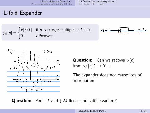
Example of Recovery from Decimated Signal
y [n] = x [n] where no aliasingoccurs.
freq.-domain interpretation
Question: Is the bandlimit condition |ω| < π/M necessary?What if X (ω) has a support over [π/3, π] for M = 3?
ENEE630 Lecture Part-1 14 / 37

1 Basic Multirate Operations2 Interconnection of Building Blocks
1.1 Decimation and Interpolation1.2 Digital Filter Banks
Decimation Filters
The decimator is normally preceded by a lowpass filter calleddecimator filter.
Decimator filter ensures the signal to be decimated is bandlimitedand controls the extent of aliasing.
ENEE630 Lecture Part-1 15 / 37
1 Basic Multirate Operations2 Interconnection of Building Blocks
1.1 Decimation and Interpolation1.2 Digital Filter Banks
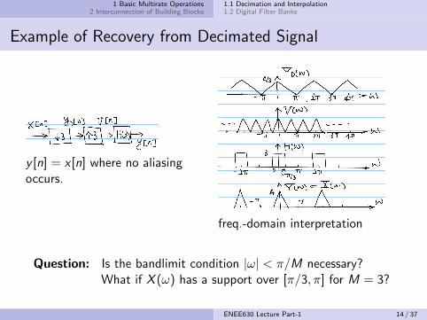
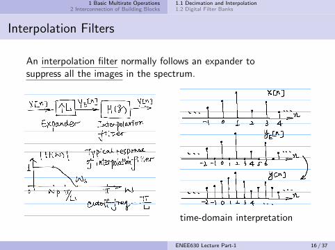
Interpolation Filters
An interpolation filter normally follows an expander tosuppress all the images in the spectrum.
time-domain interpretation
ENEE630 Lecture Part-1 16 / 37

1 Basic Multirate Operations2 Interconnection of Building Blocks
1.1 Decimation and Interpolation1.2 Digital Filter Banks
Fractional Sampling Rate Conversion
So far, we have learned how to increase or decrease sampling ratein the digital domain by integer factors.
Question: How to change the rate by a rational fraction L/M?(e.g.: audio 44.1kHz ⇐⇒ 48kHz)
Method-1: convert into an analog signal and resample
Method-2: directly in digital domain by judicious combinationof interpolation and decimation
Question: Decimate first or expand first? And why?
ENEE630 Lecture Part-1 17 / 37

1 Basic Multirate Operations2 Interconnection of Building Blocks
1.1 Decimation and Interpolation1.2 Digital Filter Banks
Fractional Rate Conversion
Use a low pass filter with passband greater than π/3 and stopbandedge before 2π/3 to remove images
Equiv. to getting 2 samplesout of every 3 original samples
the signal now is criticallysampled
some samples kept areinterpolated from x [n]
ENEE630 Lecture Part-1 18 / 37

1 Basic Multirate Operations2 Interconnection of Building Blocks
1.1 Decimation and Interpolation1.2 Digital Filter Banks
Time Domain Descriptions of Multirate Filters
Recall:
1
2
ENEE630 Lecture Part-1 19 / 37

1 Basic Multirate Operations2 Interconnection of Building Blocks
1.1 Decimation and Interpolation1.2 Digital Filter Banks
Summary of Time Domain Description
Input-output relation in the time domain for three types ofmultirate filters:
y [n] =
∑∞
k=−∞ x [k]h[nM − k] M-fold decimation filter∑∞k=−∞ x [k]h[n − kL] L-fold interpolation filter∑∞k=−∞ x [k]h[nM − kL] M/L-fold decimation filter
Note: Systems involving expander and decimator (plus filters) arein general linear time-varying (LTV) systems.
ENEE630 Lecture Part-1 20 / 37

1 Basic Multirate Operations2 Interconnection of Building Blocks
1.1 Decimation and Interpolation1.2 Digital Filter Banks
Digital Filter Banks
A digital filter bank is a collection of digital filters, with a commoninput or a common output.
Hi (z): analysis filters
xk [n]: subband signals
Fi (z): synthesis filters
SIMO vs. MISO
Typical frequency response for analysis filters:
Can be
marginally overlapping
non-overlapping
(substantially) overlapping
ENEE630 Lecture Part-1 21 / 37

1 Basic Multirate Operations2 Interconnection of Building Blocks
1.1 Decimation and Interpolation1.2 Digital Filter Banks
Review: Discrete Fourier Transform
Recall:M-point DFT
time-domaindiscrete periodic
⇒ frequency-domaindiscrete periodic{
DFT: X[k] =∑M−1
n=0 x [n]W nk
IDFT: x [n] = 1M
∑M−1k=0 X[k]W−nk
(W = e−j2π/M)
Subscript is often dropped from WM if context is clear
The M ×M DFT matrix W is defined as [W]kn = W kn
We use W∗ to represent the conjugate of W;also note W = WT (symmetric)
indexing convention in signal vector: [x [0], x [1], ...]T ,i.e. oldest first
ENEE630 Lecture Part-1 22 / 37

1 Basic Multirate Operations2 Interconnection of Building Blocks
1.1 Decimation and Interpolation1.2 Digital Filter Banks
DFT Filter Bank
Consider passing x [n] through a delay chainto get M sequences {si [n]}: si [n] = x [n − i ]
i.e., treat {si [n]} as a vector s[n], then apply W∗s[n] to get x [n].(W∗ instead of W due to newest component first in signal vector)
Question: What are the equiv. analysis filters?And if having a multiplicative factor αi to the si [n]?
ENEE630 Lecture Part-1 23 / 37

1 Basic Multirate Operations2 Interconnection of Building Blocks
1.1 Decimation and Interpolation1.2 Digital Filter Banks
Input-Output Relation of DFT Filter Bank
(details)
ENEE630 Lecture Part-1 24 / 37

1 Basic Multirate Operations2 Interconnection of Building Blocks
1.1 Decimation and Interpolation1.2 Digital Filter Banks
Relation between Hi(z)
(details)
ENEE630 Lecture Part-1 25 / 37

1 Basic Multirate Operations2 Interconnection of Building Blocks
1.1 Decimation and Interpolation1.2 Digital Filter Banks
Uniform DFT Filter Bank
A filter bank in which the filters are related by
Hk(z) = H0(zW k)
is called a uniform DFT filter bank.
The response of filters |Hk(ω)| have a large amount of overlap.
ENEE630 Lecture Part-1 26 / 37

1 Basic Multirate Operations2 Interconnection of Building Blocks
1.1 Decimation and Interpolation1.2 Digital Filter Banks
Time-domain Interpretation of the Uniform DFT FB
(details)
ENEE630 Lecture Part-1 27 / 37

1 Basic Multirate Operations2 Interconnection of Building Blocks
1.1 Decimation and Interpolation1.2 Digital Filter Banks
Time-domain Interpretation of the Uniform DFT FB
The DFT filter bank can be thought of as a spectrum analyzer
The output {xk [n]}M−1k=0 is the spectrum captured based onthe most recent M samples of the input sequence x [n].
The filters themselves are not very good: wide transitionbands and poor stopband attenuation of only 13dB– due to the simple rectangular sliding window H0(z).
Question: How can we improve the filters in the uniform DFTfilter bank, esp. the prototype filter H0(z)?
ENEE630 Lecture Part-1 28 / 37

1 Basic Multirate Operations2 Interconnection of Building Blocks
2.1 Decimator-Expander Cascades2.2 Noble Identities
Interconnection of Building Blocks: Basic Properties
Basic interconnection properties:
}by the linearity of ↓ M & ↑ L
Readings: Vaidyanathan Book §4.2; tutorial Sec. II B
ENEE630 Lecture Part-1 30 / 37

1 Basic Multirate Operations2 Interconnection of Building Blocks
2.1 Decimator-Expander Cascades2.2 Noble Identities
Decimator-Expander Cascades
Questions:
1 Is y1[n] always equal to y2[n]? Not always.
E.g., when L = M, y2[n] = x [n], but
y1[n] = x [n] · cM [n] 6= y2[n], where cM [n] is a comb sequence
2 Under what conditions y1[n] = y2[n]?
ENEE630 Lecture Part-1 31 / 37

1 Basic Multirate Operations2 Interconnection of Building Blocks
2.1 Decimator-Expander Cascades2.2 Noble Identities
Example of Decimator-Expander Cascades
0 2 4 6 8 10-2
0
2
4x0
0 1 2 3 4-2
0
2
4x1
0 5 10 15-2
0
2
4y1
0 10 20 30-2
0
2
4x2
0 5 10 15-2
0
2
4y2
0 0.2 0.4 0.6 0.8 10
0.5
1L = 3, M = 2
0 2 4 6 8 10-2
0
2
4x0
0 0.5 1 1.5 2-2
0
2
4x1
0 5 10-2
0
2
4y1
0 20 40 60-2
0
2
4x2
0 5 10 15-2
0
2
4y2
0 0.2 0.4 0.6 0.8 10
0.5
1L = 6, M = 4
ENEE630 Lecture Part-1 32 / 37

1 Basic Multirate Operations2 Interconnection of Building Blocks
2.1 Decimator-Expander Cascades2.2 Noble Identities
Condition for y1[n] = y2[n]
Examine the ZT of y1[n] and y2[n]: (details)
ENEE630 Lecture Part-1 33 / 37

1 Basic Multirate Operations2 Interconnection of Building Blocks
2.1 Decimator-Expander Cascades2.2 Noble Identities
Condition for y1[n] = y2[n]
Equiv. to examine the condition of{W k
M
}M−1k=0
≡{W kL
M
}M−1k=0
:
iff M and L are relatively prime.
Question: Prove it. (see homework).
⇒ Thus the outputs of the two decimator-expander cascades,Y1(z) and Y2(z), are identical and (a) ≡ (b) iff M and L arerelatively prime.
ENEE630 Lecture Part-1 34 / 37

1 Basic Multirate Operations2 Interconnection of Building Blocks
2.1 Decimator-Expander Cascades2.2 Noble Identities
The Noble Identities
Recall: the cascades of decimators and expanders with LTI systemsappeared in decimation and interpolation filtering.
Question:
⇒ Generally “No”.
Observations:
ENEE630 Lecture Part-1 35 / 37

1 Basic Multirate Operations2 Interconnection of Building Blocks
2.1 Decimator-Expander Cascades2.2 Noble Identities
The Noble Identities
Consider a LTI digital filter with a transfer function G (z):
Question: What kind of impulse response will a filter G (zL) have?
Recall: the transfer function G (z) of a LTI digital filter is rational for
practical implementation, i.e., a ratio of polynomials in z or z−1. There
should not be terms with fractional power in z or z−1.
ENEE630 Lecture Part-1 36 / 37

1 Basic Multirate Operations2 Interconnection of Building Blocks
2.1 Decimator-Expander Cascades2.2 Noble Identities
Proof of Noble Identities
details
ENEE630 Lecture Part-1 37 / 37