Embed Size (px)
Citation preview

P/N 340-1174-001 REV B
White Paper
Multi-Protocol Label Switching (MPLS) and Core Router TestingMarch 2003

Spirent Communications, Inc.27349 Agoura RoadCalabasas Hills, CA 91301 USA
Email: [email protected]: www.spirentcom.com
North America+1-800-927-2660
Europe, Middle East, Africa+33-1-6137-2250
Asia Pacific+852-2166-8382
All Other Regions+1-818-676-2683
Copyright© 2003 Spirent Communications, Inc. All Rights Reserved.
All of the company names and/or brand names and/or product names referred to in this document, in particular, the name “Spirent” and its logo device, are either registered trademarks or trademarks of Spirent plc and its subsidiaries, pending registration in accordance with relevant national laws. All other registered trademarks or trademarks are the property of their respective owners.
The information contained in this document is subject to change without notice and does not represent a commitment on the part of Spirent Communications. The information in this document is believed to be accurate and reliable, however, Spirent Communications assumes no responsibility or liability for any errors or inaccuracies that may appear in the document.

Multi-Protocol Label Switching (MPLS) and Core Router Testing
Contents
Introduction . . . . . . . . . . . . . . . . . . . . . . . . . . . . . . . . . . . . . . . . . . . . . . . . . . . . . . . . . . . . . . . . 2
What to Test . . . . . . . . . . . . . . . . . . . . . . . . . . . . . . . . . . . . . . . . . . . . . . . . . . . . . . . . . . . . . . . . 2
Case Studies . . . . . . . . . . . . . . . . . . . . . . . . . . . . . . . . . . . . . . . . . . . . . . . . . . . . . . . . . . . . . . . . 3
Conclusions . . . . . . . . . . . . . . . . . . . . . . . . . . . . . . . . . . . . . . . . . . . . . . . . . . . . . . . . . . . . . . . 29
Glossary . . . . . . . . . . . . . . . . . . . . . . . . . . . . . . . . . . . . . . . . . . . . . . . . . . . . . . . . . . . . . . . . . . 30
Spirent Communications White Paper | 1

Introduction
IntroductionIn the past few years, core routers have undergone rapid redesign in order to meet the changing requirements of the market. These requirements include:
• Support for high-speed optical (POS) interfaces
• Ability to handle a large number of address prefixes (over one hundred thousand) and a large number of traffic streams
• Mechanisms to facilitate traffic engineering
• Provide Quality-of-Service (QoS).
In response to these requirements, to varying degrees, the new core routers have implemented many of the routing/switching functions in specialized hardware. Many also support Multi-Protocol Label Switching (MPLS) in addition to traditional IP routing protocols such as BGP, OSPF, and IS-IS.
These new core routers present fresh challenges to test engineers who must measure the performance of these devices under realistic as well as extreme (worst-case) conditions. This document discusses the performance testing methodology by examining a series of common test cases.
What to TestTesting of networking devices usually consists of the following:
• Conformance testing
• Interoperability testing
• Performance testing.
The focus of conformance testing is to ensure that implementations comply with established standards. In the case of core router testing, this implies compliance with protocols such as BGP4, MPLS-BGP, RSVP-TE, LDP, and CR-LDP. For each protocol, the device under test (DUT) will undergo a large number of test cases which seek to verify that protocol messages are formatted correctly, that the DUT responds correctly to proper requests and that it returns the appropriate error messages when it receives an invalid request. Because of the sheer number of test cases involved, conformance testing is usually done with the help of an automated test suite.
The focus of interoperability testing is to verify that different implementations work together. This is also done by running through a number of test cases. However, the focus of these tests is to verify the proper operation of typical functions such as connection establishment, routing exchange and update, LSP (Label Switched Path) establishment and teardown, and error recovery.
Performance testing is used to measure the capacity of the DUT under normal as well as overloaded conditions. Traditional network interconnect devices are tested using the
2 | Spirent Communications White Paper

Case Studies
methodology described in RFCs 1242 (Benchmarking Terminology for Network Interconnection Devices) and 2544 (Benchmarking Methodology for Network Interconnect Devices). With the new core routers, new techniques have to be developed to supplement the traditional testing methodology to address the new functionality. For example, the traditional router metrics focus exclusively on the data handling capabilities of the DUT by measuring metrics such as throughput, back-to-back, latency, and frame loss ratio. However, the performance of the control plane is not measured using the traditional method. In the new core routers, the following questions are of particular interest:
• How is performance affected by the size of the routing table?
• What happens when there is a large number of traffic streams?
• What happens to the data traffic when there is flapping of a large number of routes?
• How effective is route flap damping?
• What is the performance difference between layer 3 routing versus label switching?
• How does the role of the MPLS router in the network (ingress, transit, or egress) affect its performance?
• How is the LSP setup rate affected by the number of established LSPs?
• How well is traffic distributed when there are multiple LSPs between a pair of BGP routers?
• How fast can traffic switch over to the secondary path if a link or node on the primary path fails?
Thus, to fully test the performance of the new generation of core routers, user plane traffic generation must be closely coupled with control plane emulation.
Case StudiesIn this section, a series of test cases will be described and analyzed. The purpose of these test cases is to illustrate the testing techniques as well as to highlight typical device behavior that one might likely uncover while performing these tests.
Throughput and Latency
The test configuration of a basic throughput and latency test is shown in Figure 1 on page 4. Traffic is injected into the router from one or more input ports and then measured on the output ports. This test configuration is applicable to a pure BGP network as well as a BGP/MPLS network. The routing table or LSP forwarding table must first be set up to ensure that the input traffic is forwarded to the appropriate output ports. This can be done either by static configuration (static routes or static LSP) or automatically by injecting control traffic from the test instrument. In BGP testing, this means injecting BGP routes to
Spirent Communications White Paper | 3

Case Studies
set up the routing table in the DUT. In MPLS testing, this means using a label distribution protocol1 to set up the required LSPs through the DUT.
Figure 1. Basic Throughput and Latency Test
Routers and switches often use a routing cache to increase throughput. In some implementations, the routing cache mirrors the routing table. In other implementations, each destination address (host address) represents an entry in the routing cache. The throughput of the DUT therefore depends partly on how fast the routing cache can be populated. To test the limit of these devices, a large number of routes need to be injected into the DUT to fill up the routing table. At the same time, the input traffic must represent a large number of different destination addresses simulating many simultaneous traffic streams.
Figure 2 on page 5 shows the configuration of a BGP router test. An AX-4000 was used to simulate two BGP routers. The DUT was configured as AS 1, whereas two ports on the AX-4000 were configured as AS 2 and AS 3 respectively. BGP routes were injected into the DUT. Note that the BGP prefixes were not contiguous to prevent the DUT from aggregating the addresses. Because of the 25-bit mask, addresses such as 195.0.0.128/25, 195.0.1.128/2 and so on, were not advertised. The DUT was therefore forced to keep a large number of entries in the routing table instead of summarizing them for example, as
1. Currently, there are a number of label distribution protocols that have been proposed in RFCs and Internet Drafts. These include RSVP with Traffic Engineering extensions (RSVP-TE), Label Distribution Protocol (LDP), Constraint-based Routing LDP (CR-LDP), and MPLS-BGP. These protocols all define signaling mechanisms that can be used to estab-lish an LSP by distributing a set of labels along the path.
DUT
Data and ControlTraffic
4 | Spirent Communications White Paper

Case Studies
195.0.0.0/16. After the routes had been injected, data traffic was generated and the throughput and latency could be measured..
Figure 2. Testing a BGP Router
High-End Router
A high-end router was tested using OC-48 interfaces. With 60-byte frames, the maximum data rate was about 4.6 million frames per second. No frames were dropped at that rate and the latency varied between 5.3 and 6.9 microseconds. The throughput and latency remained the same even when 100,000 routes were injected and the data traffic simulated 1 million streams (1 million different destination addresses).
Mid-Range Router
A mid-range (departmental) router was then tested. It was found that the number of routing table entries also had little impact on performance. This was verified for up to 100,000 routes. However, using route caching on this router revealed possible degradation when there was a large number of streams. This is shown in Figure 3 on page 6. With route cache, each destination address triggered an entry to the added to the cache. However, while the router was busy forwarding traffic, it could not populate the route cache fast enough at the same time. As a result, a high percentage of the frames were initially dropped until the route cache was gradually updated. The figure shows that it took almost 60 seconds for the throughput to reach its maximum value. Fortunately, this router also supported an option to download the entire routing table to the interface card. This eliminated the need to maintain a route cache and it was found that once this function was activated, the throughput reached its maximum level immediately.
AS 1AS 2 AS 3BGP update
Data
BGP update
Data
195.0.0.0/25195.0.1.0/25195.0.2.0/25195.0.3.0/25195.0.4.0/25...
196.0.0.0/25196.0.1.0/25196.0.2.0/25196.0.3.0/25196.0.4.0/25...
Spirent Communications White Paper | 5

Case Studies
Figure 3. Throughput with Route Cache
Low-End Router
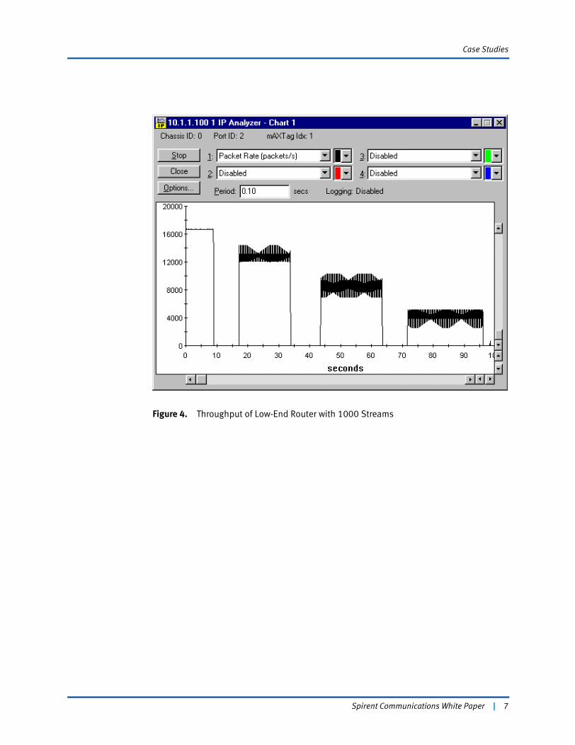
A workgroup router (obviously not designed as a core router) was deliberately tested to illustrate the impact of route caching on performance. This router exhibited similar behavior to the mid-range router in that the route cache had to be populated before traffic could be forwarded. However, unlike the mid-range router, the low-end router did not have the required processing power to update the route cache when it was bombarded with incoming traffic. The incoming traffic had to be stopped and restarted to give it time to update the route cache. Every time traffic resumed, the output rate was higher than before because the route cache had more entries. This is illustrated in Figure 4 on page 7 when 1000 streams were used in the input traffic.
6 | Spirent Communications White Paper
Case Studies
Figure 4. Throughput of Low-End Router with 1000 Streams
Spirent Communications White Paper | 7

Case Studies
Figure 5 shows that the router was struggling even more when 5000 streams were used. It took even longer for the route cache to be updated.
Figure 5. Throughput of Low-End Router with 5000 Streams
Route Flapping
This test was performed to measure the impact of route flapping on the forwarding rate. The same configuration was used as before. However, two static routes were also manually configured into the DUT. In this test, the data traffic was routed using the static routes. In theory, the data traffic should have been unaffected by any BGP updates or withdrawal. This is illustrated in Figure 6 on page 9.
8 | Spirent Communications White Paper

Case Studies
Figure 6. Testing the Effect of Route Flapping
High-End Router
When a high-end router was tested, it was found that the BGP update had an impact on the throughput. As Figure 7 on page 10 shows, the output dropped slightly (from 5.96 million packets per second [Mpps] to 5.66 Mpps) when 60,000 routes were either injected or withdrawn. The lower output rate would persist for some time. However, if the traffic was briefly stopped and then restarted, the output would bounce back to the previous level. This is illustrated in Figure 8 on page 11.
AS 1AS 2 AS 3
Data: 193.x.x.x to 194.x.x.x
193.0.0.0/8 and 194.0.0.0/8 defined as static routes in DUT
60,000 routes flapping(Updated and withdrawn)
195.0.0.0/25195.0.1.0/25195.0.2.0/25195.0.3.0/25195.0.4.0/25…195.234.95.0/25
Spirent Communications White Paper | 9

Case Studies
Figure 7. Effect of Withdrawing 60,000 Routes
10 | Spirent Communications White Paper

Case Studies
Figure 8. Stopping and Starting Traffic
The likely explanation for this behavior is that when there was a large number of routing changes, some resources in the router were tied up, thus lowering the output slightly. When traffic was stopped, it allowed the housekeeping function to continue, thus releasing the resources, and performance bounced back to the previous level.
Low-End Router
A low-end router was again tested to illustrate how route flapping can have a detrimental effect on the throughput if the DUT does not have sufficient processing power. Figure 9 on page 12 shows the output as 10,000 routes were withdrawn. Output dropped drastically for almost 10 seconds while the DUT was busy updating the routing table. Keep in mind again that the input traffic used the static routes defined and should not have been affected by the route changes.
Spirent Communications White Paper | 11

Case Studies
Figure 9. Effect of Route Flapping on Low-End Router
Route Flap Damping
The previous tests illustrated the potential adverse impact of route changes. Performance of the network can be severely affected when routes are updated and withdrawn repeatedly due to unstable links or nodes. RFC 2439 (BGP Route Flap Damping) defines a mechanism that suppresses routes that have been flapping. For each route, a figure-of-merit is kept, which is incremented every time the route is either updated or withdrawn. When the figure-of-merit reaches a cutoff threshold, the route will be suppressed. Over time, the figure-of-merit will decay exponentially (assuming the flapping has stopped). The half-life decay is a configurable parameter that specifies how long it takes the figure-of-merit to decrease to half its original value. When the figure-of-merit decreases to the reuse threshold, the route can be activated again.
12 | Spirent Communications White Paper

Case Studies
Figure 10 shows the setup to verify the proper operation of route flap damping. Route flap damping was turned on for one of the interfaces and off for the other. The following damping parameters were used:
• Figure-of-merit for each update or withdrawal = 1000
• Cutoff threshold = 3000
• Reuse threshold = 750
• Half-life decay = 15 minutes
Figure 10. Testing Route Flap Damping
Routes from both autonomous systems were updated, then withdrawn and then updated again. This resulted in a figure-of-merit value of 3000 for each route. Routes from AS 2 were suppressed due to damping while routes from AS 3 were active. This was verified by manually examining the route table in the DUT. After 30 minutes (two half-life periods), the figure-of-merit decreased to 750 which was the reuse threshold. After a few minutes, the routes from AS 2 were reactivated. This verified the proper operation of damping.
AS 1AS 2 AS 3
Routes flapped
BGP update
195.0.0.0/25195.0.1.0/25195.0.2.0/25195.0.3.0/25195.0.4.0/25…
BGP update
196.0.0.0/25196.0.1.0/25196.0.2.0/25196.0.3.0/25196.0.4.0/25…
Damping on Damping off
Routes suppresseddue to damping
Spirent Communications White Paper | 13

Case Studies
Route Selection
The following test cases were designed to verify that the correct routes are selected based on a number of BGP path attributes. In all of these cases, the same routes were advertised from two sources. The routing table of the DUT was then examined to see which routes were selected.
LOCAL-PREF
The LOCAL-PREF attribute is used to indicate the route preference based on a local policy. Figure 11 shows the test configuration. The local preference for AS 2 was configured to be 200 while the preference for AS 3 was 100. This would be done in practice if, say, AS 2 is more reliable than AS 3 and hence the routes that it advertises are preferable. In the test, both AS 2 and AS 3 advertised the same routes. However, due to LOCAL-PREF, the routes from AS 2 were selected.
Figure 11. Route Selection Based on LOCAL-PREF
AS-PATH
The AS-PATH attribute is used by a BGP router to announce the sequence of autonomous systems that packets will traverse if its routes are accepted. In Figure 12 on page 15, AS 2
AS 1AS 2 AS 3
BGP update
195.0.0.0/25195.0.1.0/25195.0.2.0/25195.0.3.0/25195.0.4.0/25…
LOCAL-PREF=200 LOCAL-PREF=100
BGP update
195.0.0.0/25195.0.1.0/25195.0.2.0/25195.0.3.0/25195.0.4.0/25…
Routes selectedbecause of higherLOCAL-PREF
14 | Spirent Communications White Paper

Case Studies
was configured to advertise an AS path of AS 4, AS 5, and AS 6. In other words, if AS 1 uses AS 2 to send traffic to the advertised routes, the packets will also have to go through three other autonomous systems before reaching the final destination. AS 3 on the other hand, advertised an AS-PATH of AS 7 only. LOCAL-PREF for AS 2 was reset to 100. Since LOCAL-PREF was the same for both sources, the DUT picked the one with the shortest AS-PATH; in this case, AS 2.
Figure 12. Route Selection Based on AS-PATH
Multi-Exit Discriminator (MED)
MED is used by two BGP speakers within the same AS to advertise the route preference (typically based on the distance to the advertised routes1). In Figure 13 on page 16, both BGP1 and BGP2 emulated routers within the same AS. Both advertised the same routes but with different MED values. In the example, BGP1 advertised 195.x.x.x with a MED of 10 while BGP2 advertised the same routes with a MED of 20. In effect, BGP1 was informing the DUT that it was closer to 195.x.x.x than BGP2. As a result, the DUT was observed to select the routes with a lower MED.
1. In practice, the MED is usually the IGP metric to the route being advertised.
AS 1AS 2 AS 3
BGP updateAS-PATH=AS4, AS5, AS6
195.0.0.0/25195.0.1.0/25195.0.2.0/25195.0.3.0/25195.0.4.0/25…
BGP updateAS-PATH=AS7
195.0.0.0/25195.0.1.0/25195.0.2.0/25195.0.3.0/25195.0.4.0/25…
Routes selectedbecause of shorterAS-PATH
Spirent Communications White Paper | 15

Case Studies
Figure 13. Route Selection Based on MED
Routing versus Label Switching
One of the benefits of label switching cited by early MPLS proponents was improved performance. Pure IP routing requires routers to perform a longest prefix match whereas label switching operates on a fixed length short label. It was therefore believed that MPLS routers would have a higher performance compared to IP routers. However, the current belief is that with recent advancements in hardware design, there is not expected to be significant performance differences between the two. Therefore it is interesting to test the theory to determine if indeed there is any difference.
Comparing a pure IP router to a different MPLS router is not very meaningful because the two routers may be implemented on different hardware platforms and may not have the same processing power. Any performance differences observed cannot be attributed to IP routing versus MPLS. Fortunately, all MPLS routers also act as an IP router for frames that do not carry a label and for which a LSP tunnel is not available. Thus, measuring the IP routing performance is straightforward using the methodology described in “Throughput and Latency” on page 3.
AS 1
AS 2
BGP update
195.x.x.x MED=10196.x.x.x MED=20
BGP update
195.x.x.x MED=20196.x.x.x MED=10
Routes selectedbecause of lowerMED
BGP1 BGP2
16 | Spirent Communications White Paper

Case Studies
After the IP routing performance has been determined, we must measure the performance of label switching. This can be done using the configuration as shown in Figure 14. Two SmartBits TeraMetrics cards were used to emulate an ingress and egress router. RSVP-TE1 was used to set up an LSP. LSR1 (Label Switching Router) sent a PATH message to its downstream neighbor LSR2. The PATH message contained the Label Request Object and an LSP Tunnel IPv4 Session Object, which identified LSR3 as the target2. LSR2 (the DUT) sent the PATH message to the egress router LSR3. LSR3 returned a label to LSR2 and LSR2 returned a label to LSR1. Using this label, data traffic was generated from LSR1 to LSR3 via LSR2. The throughput and the latency were measured using the same technique as before.
Figure 14. Testing an MPLS Router
1. In all of the tests described in this document, RSVP-TE was the label distribution protocol used. However, the same techniques can also be used with the other label distribution proto-cols.
2. The PATH message can also carry the Explicit Route Option (ERO). This gives us addi-tional control over the nodes and links along the path. Without ERO, the DUT will calculate what it considers to be the optimal path, typically by using a constrained short path first algorithm.
RSVP-TE RSVP-TE
PATH
RESV (label=30)
RESVCONF
PATH
RESV (label=16)
RESVCONF
Emulates Ingress router Emulates
Egress router
Labeled Traffic
SmartBits 600/6000B
LSR1 LSR2 LSR3
Spirent Communications White Paper | 17

Case Studies
In the devices that were tested, no significant differences in throughput or latency were observed. The results will be discussed in detail in “Modes of Operation and Performance” on page 20. Ironically, for high-end routers (especially wire-speed routers), the throughput of label switching is actually lower because of the presence of the MPLS shim header. For example, on an OC-48 link, the maximum frame rate for a 40-byte IP datagram is about 6.11 million packets per second (Mpps). If label switching is used, each frame will be 4 bytes longer, thus reducing the maximum frame rate to 5.65 Mpps (a reduction of about 8%). This represents the additional overhead of label switching.1
Signaling Performance
If MPLS is deployed in a large network, it will have to handle a large number of LSPs. Thus, it is of interest to measure the signaling performance of an LSR.
The test setup was the same as in Figure 14 on page 17. In each test, 5000 LSPs were established. The test script measured the setup time, which was the difference between the time the PATH message was transmitted and the time the RESV message carrying a valid label was received. To simplify the analysis, the test script only generated a timestamp for every 100 LSPs.
Three different DUTs were tested. They all exhibited similar behavior in that the setup time was short when there were few established LSPs. For example, it might take 1 second to set up the first 100 LSPs. However, once say, 3000 LSPs have been established, the time required to set up an additional 100 LSPs would increase to a few seconds. This is because the established LSPs still required signaling messages to keep the paths up. This involved a constant exchange of PATH and RESV messages between the ingress and egress nodes. However, the transit node also had to process all of these messages and that affected its ability to set up new paths.
One complication in measurement was that while the transit node accounted for some of the delay, the ingress and egress node (in this case, the TeraMetrics cards in a SmartBits) also contributed to the end-to-end delay. To eliminate the effect of the ingress and egress nodes, the two TeraMetrics cards were connected back-to-back and the same test was repeated. This provided a baseline measure of the processing time inside the SmartBits. This number was then subtracted from each of the measurements involving the DUT, which isolated the processing time of the DUT alone.
The results were plotted in Figure 15 on page 19. The graph shows that in all three implementations, the setup time increased rather rapidly after about 4000 LSPs. These results indicate that in a core network with a large number of LSPs, the time required to set up new LSPs can become an issue. This is an important consideration in error recovery when a large number of LSPs may have to be set up to bypass a failure.
1. In fact, the overhead is even higher if one includes the control plane traffic. To keep the LSP up, keepalive messages have to be sent and this consumes additional (albeit little) band-width.
18 | Spirent Communications White Paper

Case Studies
Figure 15. Signaling Performance
0
5
10
15
20
25
30
0 1000 2000 3000 4000 5000 6000
Number of labels
Setu
p Ti
me/
100
labe
ls(s
econ
ds)
DUT1DUT2DUT3
Spirent Communications White Paper | 19

Case Studies
Modes of Operation and Performance
Within an MPLS network, an LSR can act as an ingress node, a transit node, an egress node, or a pure IP router. The operation of each mode is summarized in the following table:
Mode Operation Remarks
Ingress Layer 3 lookup
PUSH a label
The ingress node receives regular IP frames and then retransmits them in the MPLS network by inserting a label.
Transit Label lookup
SWAP label
The transit node receives a labeled frame from an input port, swaps the label after looking up a table, and then retransmits it on the output port.
Penultimatea
(label 0)
a There was a concern that since the egress node has to perform two lookups—a label lookup followed by a layer 3 lookup—there might be a performance penalty in some implementations. One way around that is Penultimate Hop Popping (PHP). With PHP, the egress node either returns a label of 0 (explicit NULL) or 3 (implicit NULL). When the egress node sees a label of 0, it knows that it is the egress node and no label lookup is necessary. Alternatively, the egress node can signal a label of 3, which forces the pen-ultimate LSR to pop the label before sending it to the egress node. For a more detailed explanation of PHP, please refer to RFC 3031 (MPLS Architecture) “Setting up for Dif-ferent Modes of Operation” on page 21.
Label lookup
SWAP label
This is identical to transit node except that the outgoing label is 0.
Penultimate
(label 3)
Label lookup
POP label
During signaling, if the egress node returns a label of 3, the penultimate LSR must pop the label before forwarding the frame.
Egress
(no PHP)
Label lookup
POP label
Layer 3 lookup
Without PHP, the egress node must perform two table lookups, first looking up the label table and then looking up the IP routing table.
Egress
(label 0)
POP label
Layer 3 lookup
A label 0 is an explicit NULL. It indicates that the frame has reached the egress node. Thus, no label lookup is necessary.
Egress
(label 3)
Layer 3 lookup Since the penultimate LSR has already popped the label, the egress node only has to look up its routing table to forward the frame.
IP routing Layer 3 lookup If the incoming frame has no label and there is no LSP to the next hop, the frame will be routed just as in traditional IP routing.
20 | Spirent Communications White Paper

Case Studies
Thus, depending on the location of the LSR in the MPLS network, its operation can be different and so can its performance. It is therefore quite interesting to test the performance of an MPLS router for each of these modes of operation. However, some of these modes perform the identical functions and therefore do not need to be tested separately. For example, an egress node that signals label 3, performs the same function as in IP routing and therefore should have the same performance.
Setting up for Different Modes of Operation
Depending on the capabilities of the DUT, setting up the different modes of operation can be challenging. The following paragraphs describe a few typical examples.
Ingress node
The easiest way to set up this test is to use manual label assignment as shown in Figure 16. The ingress node was configured to push a label of 123 whenever it received frames destined for 192.172.0.0/16. Once the label had been configured, data traffic destined for 192.172 was injected into the DUT and the throughput and latency of the ingress node could then be measured..
Figure 16. Ingress Node Testing
Transit node
The setup for this test was the same as the one shown in Figure 14 on page 17. The SmartBits was used to signal from end to end with the DUT acting as a transit node.
192.172.0.0/16 next-hop R1push 123
IP to 192.172.0.2Label 123
Ingress router
R1
Spirent Communications White Paper | 21

Case Studies
Egress node (label 0)
Traffic carrying a label of 0 was injected into the DUT as shown in Figure 17. The egress node popped the label and routed the remaining frame using the IP header..
Figure 17. Egress Node Testing
Egress node (no PHP)
The test was performed using manual configuration as shown in Figure 18. The DUT was configured to pop the label of 25 and route the remaining frame.
Figure 18. Egress Node (no PHP) Testing
Label 0IP to 192.171.0.1
IP to 192.171.0.1
Egress router
Label 25IP to 192.171.0.1
IP to 192.171.0.1
Egress router
Label 25 pop
22 | Spirent Communications White Paper

Case Studies
Test Results
Two different DUTs were tested using the techniques described in “Setting up for Different Modes of Operation” on page 21. For the first DUT, the focus of the test was on the maximum output rate. The following table summarizes the results1.
For this DUT, there was indeed a performance improvement when the router was acting as an MPLS transit node as opposed to being used for IP routing. Using 60-byte frames, the highest frame rate was 293.7 kilopackets per second compared to 260 when routing IP frames. This represented a performance increase of about 13 percent. Unfortunately, when the same node was tested as an egress node (the LSR must pop the label before a layer 3 lookup), the performance dropped to 234 kilopackets per second. Based on these results, if this DUT was used to implement all the nodes in an MPLS network, the end-to-end performance would actually be lower than a pure layer 3 network.
In a second test, a high-end router was tested. The following modes were tested:
• IP routing
• Ingress
• Transit
• Egress (without PHP)
• Egress (with label 0).
There was no difference in throughput in all cases. The latency was measured to be between 6 and 7 microseconds. Interestingly, the latency of IP routing and egress (with label 0) was very slightly (less than one microsecond) faster than the other modes.
1. Since this DUT did not support manual label assignment, the performance of this DUT as an ingress node and as an egress node without PHP was not measured.
Frame Size (Octets)
Maximum Frame Rate (Thousands of packets per second)
IP Routing Transit Node Egress Node (label 0)
60 260 293.7 234
70 256 274 232.5
80 253 263 231.3
100 217 215.4 219.5
500 72.7 73.1 71.5
1000 36.3 36.4 36.2
1500 24.3 24.3 24.3
Spirent Communications White Paper | 23

Case Studies
Quality-of-Service
In Differentiated Services, packets are classified and marked with a Diff-Serv Code Point (DSCP), which identifies their Behavior Aggregate (BA). At each transit node, the DSCP determines the Per Hop Behavior (PHB), which indicates the treatment of the frame and its drop precedence. If the data frames are carried in an MPLS network, then a mechanism is required to map the traffic to the appropriate treatment. In the Internet Draft MPLS Support of Differentiated Services (draft-ietf-mpls-diff-ext), two mechanisms have been proposed:
• Label-Only-Inferred-PSC LSPs (L-LSP): During signaling, the PHB scheduling class (PSC) is specified so that the LSR can infer from the label value the PHB to be applied to a labeled packet.
• EXP-Inferred-PSC LSPs (E-LSP): The EXP field of the MPLS shim header is used to map to 8 BAs. Thus, a single LSP can be used to support up to 8 BAs of a given FEC.
To verify the proper treatment of traffic with different QoS levels, we must create some contention in the network and then observe how traffic with higher priority is treated vis-à-vis traffic with lower priority.
A DUT that supports E-LSP was tested as shown in Figure 19 on page 25. Two streams of traffic were injected into the DUT acting as an ingress node. The DUT was configured to map traffic destined for network 194 to label 100 with a class-of-service of 0 in the EXP field. Traffic destined for network 193 would be directed to label 107 with a class-of-service of 7. Since there was contention in the network, traffic received by the SmartBits would indicate any priority treatment of traffic for network 193. Indeed, traffic destined for network 193 experienced a lower frame loss rate compared with traffic for network 194, as expected.
24 | Spirent Communications White Paper

Case Studies
Figure 19. Testing QoS with E-LSP
The frames were also captured from the receiving end as shown in Figure 20 on page 26. This allowed the shim header to be examined to ensure that the EXP field had been coded correctly. The two shim headers captured were:
00-06-41-3FLabel: 0x00064 (100 decimal)
EXP: 000
Bottom of stack: 1
TTL: 0x3F (63 decimal)
00-06-BF-3FLabel: 0x0006B (107 decimal)
EXP: 111 (7 decimal)
Bottom of stack: 1
TTL: 0x3F (63 decimal)
This verified that the EXP field was coded as configured.
194.0.0.0/8 push 100 class-of-service 0193.0.0.0/8 push 107 class-of-service 7
IP to 194.1.1.1
Label 100Exp: 0
IP to 193.1.1.1
Label 107Exp: 7
Spirent Communications White Paper | 25

Case Studies
Figure 20. Encoding of QoS in the EXP Field
Load Balancing
One of the most common applications of MPLS in a core network is traffic engineering. Within an autonomous system, if a BGP router identifies another BGP router as the next-hop, it will use the Interior Gateway Protocol (IGP) to determine the shortest path to reach the other BGP router. This can often lead to overutilized nodes and links within the AS. Using MPLS, one or more LSPs will be established between the two BGP routers. The LSPs can select physical paths based on traffic engineering requirements; for example, avoiding congested nodes and links. BGP traffic will then make use of the LSPs to reach the next hop.
If two or more LSPs are established between two BGP routers, traffic will be distributed across the different paths. This provides a more flexible load balancing mechanism than most IGPs.
Load balancing was tested in a configuration as shown in Figure 21 on page 27. Using explicit route, two LSPs were established between the ingress and egress LSRs. An AX-4000 was used to emulate a BGP peer to the egress router of the MPLS network. Routes were advertised from the AX-4000. A SmartBits was then used to inject traffic into the network. By examining the routing table and the traffic statistics, it was verified that the traffic was distributed across the two LSPs.
Shim Header
26 | Spirent Communications White Paper

Case Studies
Figure 21. Testing Load Balancing
Protection Switching
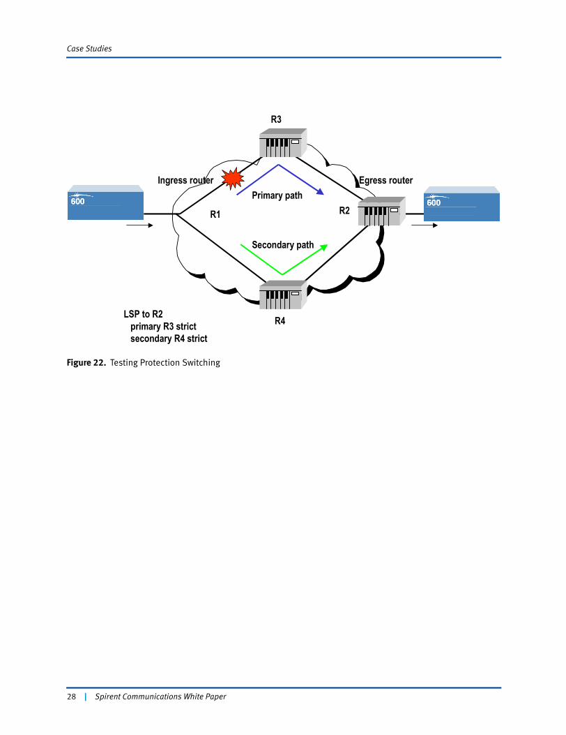
Another benefit of MPLS is that it offers a variety of recovery mechanisms. Refer to the Internet Draft Framework for MPLS-based Recovery (draft-ietf-mpls-recovery-frmwrk) for details. One of the simplest mechanisms is protection switching in which an LSP has a primary path and a secondary path. If a node or a link along the primary path fails, then traffic will be redirected to the secondary path. If the primary path is subsequently repaired, traffic will eventually switch back to the primary path. This is usually controlled by a path reoptimization timer.
Protection switching was tested in a setup like that shown in Figure 22 on page 28. One LSP was established between the ingress and egress nodes using a primary and secondary path. Traffic was injected into the network and monitored from the egress node. A link along the primary path was manually disrupted causing a link failure. It was verified that traffic then switched over to the secondary path. Furthermore, by measuring the rate at which frames were received over time, the time taken to detect the link failure and subsequently to switch paths could be measured.
Ingress router Egress routerLSP1
LSP2
R3
R4
LSP1 to R2 R3 strict
LSP2 to R2 R4 strict
BGP update
Spirent Communications White Paper | 27
Case Studies
Figure 22. Testing Protection Switching
Ingress router Egress routerPrimary path
Secondary path
R1 R2
R3
R4LSP to R2 primary R3 strict secondary R4 strict
28 | Spirent Communications White Paper

Conclusions
ConclusionsThe new breed of routers on the market has been designed to meet more demanding requirements in the core network. To varying degrees, the routing/switching functions have been implemented in specialized hardware. Many new core routers also support MPLS. While traditional metrics are useful in quantifying performance in the data plane, they do not provide meaningful measurements in the control plane. Full testing of the performance of these devices requires close coordination of user plane traffic generation and control plane emulation. This document presented testing techniques to measure BGP and MPLS performance, as well as some interesting test cases. The following is a summary of the test results:
• With hardware switching and route caching, performance is largely unaffected by routing table size.
• The performance of route caching is dependent on the number of simultaneous traffic streams. Routers with insufficient processing power suffer the most because they cannot update the route cache fast enough.
• Route flapping can have a detrimental effect on performance when the routers do not have sufficient processing power.
• Contrary to early beliefs, there is no significant difference in performance between routing and MPLS on the same hardware platform.
• There are some (usually small) performance differences depending on the mode of operation (ingress, transit, or egress).
• The setup time increases as the number of established LSP increases. This can be an important consideration during error recovery when a large number of LSPs have to be established to bypass a failure.
Spirent Communications White Paper | 29

Glossary
GlossaryAdapted from RFC 3031 (Multiprotocol Label Switching Architecture).
Behavior Aggregate
A collection of packets with the same codepoint crossing a link in a particular direction.
Datalink Connection Identifier
A label used in Frame Relay networks to identify frame relay circuits.
Forwarding Equivalence Class
A group of IP packets that are forwarded in the same manner (e.g., over the same path, with the same forwarding treatment).
frame merge
Refers to label merging, when it is applied to operation over frame based media, so that the potential problem of cell interleave is not an issue.
label
A short, fixed-length, physically contiguous identifier that is used to identify an FEC, usually of local significance.
label merging
The replacement of multiple incoming labels for a particular FEC with a single outgoing label.
label swap
The basic forwarding operation that consists of looking up an incoming label to determine the outgoing label, encapsulation, port, and other data handling information.
label swapping
A forwarding paradigm that allows the streamlined forwarding of data by using labels to identify classes of data packets that are treated indistinguishably when forwarding.
label switched hop
The hop between two MPLS nodes, on which forwarding is done using labels.
label switched path
The path through one or more LSRs at one level of the hierarchy followed by a packets in a particular FEC.
label switching router
An MPLS node that is capable of forwarding native L3 packets.
layer 2
The protocol layer under layer 3 (which therefore, offers the services used by layer 3). Forwarding, when done by the swapping of short fixed length labels, occurs at layer 2 regardless of whether the label being examined is an ATM VPI/VCI, a frame relay DLCI, or an MPLS label.
30 | Spirent Communications White Paper

Glossary
layer 3
The protocol layer at which IP and its associated routing protocols operate at the link layer synonymous with layer 2.
loop detection
A method of dealing with loops in which loops are allowed to be set up and data may be transmitted over the loop, but where the loop is later detected.
loop prevention
A method of dealing with loops in which data is never transmitted over a loop.
label stack
An ordered set of labels.
merge point
A node at which label merging is performed.
MPLS domain
A contiguous set of nodes that operate MPLS routing and forwarding and which are also in one Routing or Administrative Domain.
MPLS edge node
An MPLS node that connects an MPLS domain with a node that is outside of the domain, either because it does not run MPLS, and/or because it is in a different domain. Note that if an LSR has a neighboring host that is not running MPLS, that LSR is an MPLS edge node.
MPLS egress node
An MPLS edge node performing its role of handling traffic as it leaves an MPLS domain.
MPLS ingress node
An MPLS edge node performing its role of handling traffic as it enters an MPLS domain.
MPLS label
A label that is carried in a packet header and which represents the packet's FEC.
MPLS node
A node that is running MPLS. An MPLS node will be aware of MPLS control protocols, will operate one or more L3 routing protocols, and will be capable of forwarding packets based on labels. An MPLS node may optionally be also capable of forwarding native L3 packets.
Multi-Protocol Label Switching
An IETF working group and the effort associated with the working group.
network layer
Synonymous with layer 3.
Spirent Communications White Paper | 31

Glossary
Per-Hop Behavior
A description of the externally observable forwarding treatment applied at a differentiated services-compliant node to a behavior aggregate. The description of a PHB should be sufficiently detailed to allow the construction of predictable services.
stack
Synonymous with label stack.
switched path
Synonymous with label switched path.
virtual circuit
A circuit used by a connection-oriented layer 2 technology such as ATM or Frame Relay, requiring the maintenance of state information in layer 2 switches.
VC merge
Label merging where the MPLS label is carried in the ATM VCI field (or combined VPI/VCI field), so as to allow multiple VCs to merge into one single VC.
VP merge
Label merging where the MPLS label is carried in the ATM VPI field, so as to allow multiple VPs to be merged into one single VP. In this case, two cells would have the same VCI value only if they originated from the same node. This allows cells from different sources to be distinguished via the VCI.
VPI/VCI
A label used in ATM networks to identify circuits.
32 | Spirent Communications White Paper

Glossary
Acronyms and Abbreviations
AS
Autonomous System
ATM
Asynchronous Transfer Mode
BA
Behavior Aggregate
BGP
Border Gateway Protocol
CR-LDP
Constraint-based Routing Label Distribution Protocol
DLCI
Data Link Connection Identifier
DSCP
Diff-Serv Code Point
DUT
Device Under Test
FEC
Forwarding Equivalence Class
FTN
FEC to NHLFE Map
IGP
Interior Gateway Protocol
ILM
Incoming Label Map
IP
Internet Protocol
IS-IS
Intermediate System-Intermediate System
LDP
Label Distribution Protocol
L2
Layer 2
Spirent Communications White Paper | 33

Glossary
L3
Layer 3
LSP
Label Switched Path
LSR
Label Switching Router
MED
Multi-Exit Discriminator
MPLS
Multi-Protocol Label Switching
NHLFE
Next Hop Label Forwarding Entry
OSPF
Open Shortest Path First
PHB
Per Hop Behavior
PHP
Penultimate Hop Popping
POS
Packet Over SONET
RSVP
Resource Reservation Protocol
RSVP-TE
RSVP with Traffic Engineering extensions
SVC
Switched Virtual Circuit
SVP
Switched Virtual Path
TE
Traffic Engineering
TTL
Time to Live
34 | Spirent Communications White Paper

Glossary
VC
Virtual Circuit
VCI
Virtual Circuit Identifier
VP
Virtual Path
VPI
Virtual Path Identifier
Spirent Communications White Paper | 35

Glossary
About the Author
Angus Ma (B.Eng., M.Eng., M.B.A.)
Mr. Angus Ma began his career as a software designer for Nortel Networks (formerly Bell-Northern Research). After leaving Nortel, he developed data communications products as well as UNIX-based office systems. In 1986, Mr. Ma launched AHM Technology Corporation, which provides network design, analysis, and troubleshooting services to large corporate clients. Angus is an internationally-known speaker appearing regularly in North America, Europe, and Asia. Mr. Ma has worked in data and telecommunications since 1980 and has extensive experience in planning, implementing, managing, and analyzing large networks.
[email protected] Technology Corporation
21 Saddlebrook St.
Ottawa, Ontario
Canada K2G 5N7
36 | Spirent Communications White Paper