Embed Size (px)
Citation preview

Multi-Mission Space Vehicle Subsystem Analysis Tools Mark Kordon
Jet Propulsion Laboratory 4800 Oak Grove Drive Pasadena, CA 9 100 1
[email protected]. eov 8 18-393-0476
Abstruct- Spacecraft engineers often rely on specialized simulation tools to facilitate the analysis, design and operation of space systems. Unfortunately these tools are often designed for one phase of a single mission and cannot be easily adapted to other phases or other missions. This fiequently results in time consuming and costly redevelopment since the models need to be reworked, re- verified and revalidated whenever there is an unexpected change. The Multi-Mission Space Vehicle Subsystem Analysis Tools are designed to provide a solution to this problem. Enabled by the recent increases in commodity computer storage capacity and computation speed, and leveraging off the fact that properly parameterized models can support multiple missions and that each phase differs primarily in the level of detail, these tools are able bo provide a robust solution to space vehicle trade studies, petformance analysis and sequence development, in a package that is easy-to-use and provides fast, accurate results at a level of fidelity appropriate to each stage of the project Mecycle.
TABLE OF CONTENTS
1. INTRODUC~ION ........................................ 1 2. JPL FLIGHT PROJECT OVERVIEW ........ 2 3. MMPAT OVERVIEW .............................. 2 4. MMPAT SOFTWARE ARCHITECTU RE... 3 5. MMPAT MODELS .................................. 4 6. CONCLUSIONS .......................................... 5
1. INTRODUCTION In the past decade, the Jet Propulsion Laboratory's (JPL) deep space missions have undergone a radical change in scale. Gone are the days of large 2 billion-dollar missions with 10 to 15-year development cycles. Instead JPL is now being asked to build many smaller missions in half the time for a tenth of the cost of its previous large missions. This focus on faster, better, cheaper has caused the Laboratory to reinvent the way it builds space vehicles. To meet this challenge, JPL's Project Planning Office has been funding numerous projects aimed at enhancing the Laboratory's technical infrastructure. One of these efforts involves the development of several Multi-Mission Subsystem Analysis
Eric Wood Jet Propulsion Laboratory
4800 Oak Grove Drive Pasadena, CA 9 100 1
Eric. Wood0.id.nasa. eov 8 18-354-8984
Tools. The goal of this effort is to provide a robust solution to space vehicle trade studies, performance analysis and sequence development, for each flight system subsystem, in packages that are easy-to-use and provide fast, accurate results at a level of fidelity appropriate to each stage of the project lifecycle.
This is a radical departure fiom how tools for these types of analyses are usually developed. Traditionally, since deep space systems have tightly coupled subsystems and very complicated mechanisms that must function over long operating times in extreme environmental conditions, models are developed for each subsystem on the space vehicle so that engineers can analyze its performance before they are built. Due to the unique aspects of each mission and because previous models were developed to be mission specific, these models are fiequently built fiom scratch with little inheritance from earlier missions. Developing unique models in this manner can be costly and time consuming since they usually need to be redeveloped, re-verified and revalidated whenever there is a hardware modification or an unexpected change in the mission scenario. Furthermore, projects often build new subsystem models for every phase to take into account additional information, like test data, that was not known in the previous phase. The Multi-Mission Subsystem Analysis Tools address these issues by providing an easy-to- use, easy-to-integrate, variable fidelity, parameterized solution designed to support rapid trade studies, performance analysis and sequence development throughout the lifecycle of a flight project for a wide variety of mission types, mission phases and hardware configurations.
This paper begins by discussing the lifecycle of a JPL flight project to provide context for the work. It then gives an overview of one of the Multi-Mission Subsystem Analysis Tools: the Multi-Mission Power Analysis Tool (MMPAT). It goes on to describe features of the tool, how it fits into the JPL development process, its software architecture and its models. The paper concludes with the results of this effort and outlines future work.
' 0-7803-7651-W03/%17.00 0 2003 IEEE
1

2. JPL FLIGHT PROJECT OVERVIEW The Multi-Mission Subsystem Analysis Tools are designed to support flight projects throughout their entire lifecycle. Typically, flight projects at JPL undergo six phases, each culminating with a review:
Pre-Phase A Advanced Studies Phase A: Mission & System Deffition Phase B: Preliminary Design Phase C: Design & Build Phase D: Assembly Test & Launch Ops
0 Phase E: Operations
In Pre-Phase A, JPL detennines the feasibility of the mission and develops a study concept. Assuming that the concept gets approved the project moves into Phase A where alternative architectures are examined and preliminary requirements are developed, as well as a preliminary mission and system design. It is here that the project defines what assemblies are needed, what the cost and size will be, when to launch, what the space vehicle trajectory is and what operations will be done. In Phase B requirements, schedules and specifications are created to convert the preliminary design to a system design. When the system design is completed and reviewed, the space vehicle subsystems are designed and built in Phase C. After the subsystems are built the system is assembled, tested and launched in Phase D. Following launch the project enters Phase E where the spacecraft is operated with the goal of returning science data.
The space vehicle flight system is typically composed of several subsystems:
Power Subsystem Command & Data Handling Subsystem Telecommunications Subsystem Propulsion Subsystem Mechanical Subsystem Thermal Subsystem Guidance Navigation and Control Subsystem Spacecraft Flight Software
Each subsystem is responsible for a particular function on the space vehicle and usually deploys similar but rarely identical assemblies. The power subsystem is the part of the spacecraft that provides the rest of the vehicle with power. It consists of one or more power sources such as a solar array, an energy storage device like a battery and power distribution electronics. Command and data handling is responsible for interpreting commands from Earth, sending telemetry back to Earth and handling the system fault protection. This subsystem contains the flight computer, memory, buses and VO devices. Telecommunications is responsible for transmitting and receiving signals fiom Earth. It consists of antennas, transmitters, receivers and amplifiers. The mechanical subsystem consists of all of the
structural hardware and mechanisms in the flight system. The thermal subsystem includes all of thermal control hardware and electronics that keeps the spacecraft at the proper operating temperature. Propulsion is responsible for the engines, thrusters, fuel tanks and feed system. The guidance navigation and control subsystem is responsible for the sensors and pointing hardware. Finally the flight software provides the s o h a r e to control all of the other subsystems. It is the goal Multi-Mission Subsystem Analysis task to provide interoperable, variable fidelity, multi-mission tools for the power, telecom, propulsion, command & data handling and thermal subsystems.
3. MMPAT OVERVIEW One of the tools in the suite of Multi-Mission Subsystem Analysis Tools is MMPAT. This application will be discussed in detail because much of what is said about its relevance to a flight project and software architecture applies to the other multi-mission subsystem analysis tools, and its current uses clearly demonstrate the advantages of the multi- mission approach. MMPAT is a multiplatform software simulator used to analyze the performance and resources of space vehicle electrical power subsystems. It runs on Windows, Solaris and Linux and is distributed as either a desktop application with a Graphical User Interface (GUI) or as a linkable library package.
Figure 1 - MMPAT Graphical User Interface
MMPAT produces dynamic time and sequence dependant results rather than static point solution. As such, it models the behavior of power sources and energy storage devices as they interact with the spacecraft loads over a mission timeline. For instance, a user can use the GUI to input a power subsystem hardware configuration, initial mission and hardware conditions, and the changes in power consumption
2
and parameters over some time interval of the mission. When the simulation is run, the time-stamped power consumption and parameter changes are used to change the state of the model. This allows tremendous flexibility by permitting the user to vary the angle of the solar array with respect to the sun, for example, at any time during the sequence. Users can spec@ any time interval to run and in most cases the simulation will produce results within a few seconds. A 24-hour simulation with 5-minute time steps completes in less than 5 seconds on a 1 GHz workstation. Results are available in both tab delimited text and graphical forms. Users can review and compare power, currents, and voltages on the power sources, energy storage devices and power bus. They can also view the load profile, solar array insolation, battery state of charge, orbital angles, thermal node dissipations as well as energy source, battery and atmospheric temperatures.
Figure 2 - MMPAT SIC Power Graph
All of the models in MMPAT were developed “y power subsystem experts or adapted fiom validated heritage models. The tool comes with models for many of the most commonly used power sources, storage devices and power bus control methods used on space vehicles today. This includes, but is not limited to NiH2 and Li Ion batteries, Triple Junction and High EEciency Thin Silicon solar cells, and Radio-Isotope Thermal-Electric Generator (RTGs). To provide higher fidelity and faster analyses, MMPAT has integrated spacecraft thermal and power equipment list (PEL) capabilities as well. Since most of these models are table driven, users can easily extend the current capabilities by adding new battery chemistries and solar cells, or use data fiom actual tests. The simulation itself is controlled by model parameters. Every parameter that can be dynamically changed is located on the GUI providing the user with 111 control of the analysis and the flexibility to change the fidelity of the simulation. For example, for early trade studies the user can speciQ a fured battery temperature. When the daily battery temperature cycle is known, the user can direct the simulation to use a daily battery temperature
3
file to lookup the battery temperature. If at some point the spacecraft thermal node characteristics are known, the user can switch on the high fidelity thermal model to calculate what the battery temperature will be. It is this flexibility that allows the tool to be used throughout the flight project’s lifecycle. Moreover, the parameterized interface can also be used to change the mission type and analyze different mission phases since MMPAT supports the analysis of planetary landers, planetary orbiters, heliocentric orbiters and rovers as well as cruise, landed and orbiting phases and special events like flyby, TCM and EDL.
All of these features allow MMPAT to be used for rapid trade studies, performance analysis and sequence development throughout the lifecycle of a project for a wide variety of mission types, mission phases and hardware confgurations. In Pre-Phase A - Phase D for instance, system engineers can perform system-level trade studies and mission planners can use the model to evaluate mission scenarios. Power subsystem engineers can use the model to size various power subsystem components, such as solar arrays or batteries. In Phase E, the tool provides insight into the actual condition of a spacecraft’s power subsystem during flight and can be used in with concert activity planning tools to support the development of feasible activity plans.
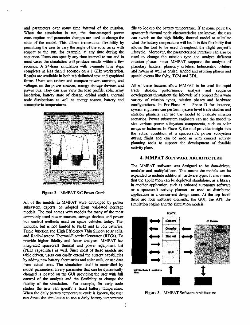
4. MMPAT SOprwARE ARCHITECTURE The MMPAT software was designed to be data-driven, modular and multiplatform. This means the models can be expanded to include additional hardware types. It also means that the application can be deployed standalone, as a library in another application, such as onboard autonomy software or a spacecraft activity planner, or used as distributed application in a concurrent design team. At the top level, there are four software elements, the GUI, the API, the simulation engine and the simulation models.
t Figure 3 - MMPAT Software Architecture

The GUI provides all of the features that one normally expects in a commercial application and allows the user to set all of the parameters in the simulation. It is written in the TcVTk scripting language and uses an extension called BLT for the graphs, both of which are compiled with the simulation code into a single executable. This gives the application the look and feel of a native application and also provides a socket interface for TCP/IP communication over a LAN or WAN. Communication between the GUI and simulation occurs through the API. This allows the GUI to be removed so that the simulation can be complied as a library.
The API is the only interface into the simulation engine and simulation models. It provides a set of function calls that are the same on every multi-mission analysis tool making it easy to integrate several tools into another application. The functions provided include the ability to load and save configuration and input profile files, write results, change parameters and advance time. This means that an application calling MMPAT has the ability to change parameter values at any time during the simulation run.
Both simulation engine and simulation models are written in the C programming language. The simulation engine uses a hybrid time-stepwevent-den time advance mechanism meaning that simulation time normally advances by equal step intervals specified by the user but if there is an event, like a change in a parameter value, the simulation will insert a time step at the time of the event. The simulation engine also monitors the changes of intemal discrete state variables and the rate of change of continuous state variables. This is so that if an intemal discrete state variable changes or a continuous variable changes too rapidly, one or more time steps will be inserted to preserve the accuracy of the results.
5. MMPAT MODELS MMPAT models are object-based meaning that structures within the soRware have a direct relationship to real world entities. The models in the simulation include:
Solar Array Model Solar Array Thermal Model Orbital Mechanics Astrodynamics Model Pointing Model Atmospheric Model Secondary Battery Model Secondary Battery/Thermostatically Controlled Heater Thermal Model Power Bus Model RTG Model Power Equipment List Model
The solar array model is a table driven mathematical s o h a r e model that allows the user to select or provide new
4
solar cell characteristics and I-V curves. MMPAT’s solar cell characteristics and I-V curves describe the behavior of a single cell under test conditions. When the simulation is run, this cell level curve is adjusted by environmental light losses, like atmospheric effects, sun distance and sun angle, and environmental factors, such as dust, that affects cell level efficiency. After these effects are accumulated a new array level curve is generated that takes into account the number of cells per string and the number of strings per array. This curve is then used to calculate the power supplied by the array at each time step for a given power bus voltage.
The solar array thermal model is a variable fidelity model used to determine the temperature of the solar cells on the solar panel. A user can choose to run the solar cells at a fned temperature, or use a daily temperature cycle file. When more information is known, segments of the solar panel can be given different absorptances and emittances so that the cell temperatures will change when the cells are exposed to different levels of light.
As previously mentioned, the solar array model works in conjunction with the orbital mechanics, astrodynamics, pointing and atmospheric models. The orbital mechanics model is a table driven, mathematical model utilizing two- body orbital mechanics equations to calculate the motion of a planet around the Sun. In MMPAT it is used to determine how far the planet is from the Sun. The astrodynamics model is a mathematical model utilizing two-body orbital mechanics equations to calculate the motion of the spacecraft around the Sun or planet. By working with the orbital mechanics model, the astrodynamics model can determine the distance the space vehicle is fiom the Sun and whether sunlight is blocked by the planet. The solar array sun angle is determined with the pointing model. This allows the user to specify a sun angle, use inertial pointing so that the spacecraft will maintain a constant angular relationship with the surrounding starscape or nadir pointing where the spacemail will maintain a constant nadir point. The atmospheric model is a table driven mathematical model that takes into account direct, d i f i e and reflected irradiation in a dusty atmosphere given optical density, zenith angle and surface albedo.
The secondary battery model is a tabular model and as such is able to support most battery chemistries. This also allows the user to substitute actual battery test data for the NiH2 and Li Ion data tables that come with the simulation. Battery voltage is modeled with a 3 dimensional table that returns battery voltage as a hc t ion of temperature, state of charge and current. Other tables may be used to specify the battery intemal heat dissipation, charge efficiency and capacity. Thus MMPAT provides a way to handle batteries with markedly different characteristics. At every time step the simulation uses these tables by frst adding the average charge current over the time step and multiplying it by the step duration in Earth hours to determine the amp-hours of

battery energy charged or discharged. When the battery is charging, the amp-hours added to the state of charge are reduced by the table specified charge inefficiency of the particular battery chemistry. Intemal heat dissipated can be determined by looking up in the internal heat dissipation table based on battery temperature, state of charge and charge/discharge current. Finally the batteries maximum capacity can be obtained either from the temperature dependant capacity table or by using the manufacture’s nameplate.
The battery thermal model is a variable fidelity model used to determine the battery temperature in a given time step. A user can choose to run it at a fixed temperature, or use a daily temperature cycle file. When more information is known, a multi-node model employing transient finite difference thermal analysis is used to calculate the temperatures of the various nodes for the purposes of determining battery and thermostatically-controlled heater performance. For th is high fidelity analysis the user must specify the thermostatically controlled heaters, heat capacitance for each node as well as the radiative and conductive links between the nodes. Nodes need not be limited to space vehicle components but can represent the boundary conditions with variable conductive links as well.
The power bus model is a software model that supports two power bus regulation methods: shunt limiter and, “string and shunt switching”. The shunt limiter operates by shunting enough current to one or more resistor arrays to maintain a specified bus voltage. The shunt resistors are energized one by one and only to the degree necessary. That means that at the lowest level, only a little current is passed to the fmt resistor and none to the others. only when the first resistor is fully utilized does the second resistor begin to receive current. Any heat dissipated by the shunt resistors and the shunt limiter unit is passed to the thermal model when it is in use. String and shunt switching operates by switching on and off the solar array strings and a small shunt resistor. The shunt resistor is sized to be the approximate equivalent of turning off half of a solar array string. The bus voltage and battery temperature are examined once per second and a decision is made whether to increase the number of strings turned on by one half, decrease the number of strings by one half or do nothing.
The power equipment list model allows the user to specify all of the power consuming loads on the space vehicle and their various states. So that rather than sending MMPAT the aggregated spacecraft power load, the state of a particular piece of equipment can be sent and the tool calculates the aggregated power load. Each load state can specify the pure power load, constant current load, resistive load, and the node in which to dissipate and power converter dissipation.
6. CONCLUSIONS This paper demonstrates that with the recent increases in commodity computer storage and computation speed, a variable fidelity, subsystem analysis tool can be developed to support the entire lifecycle of a mission. There are numerous advantages to using this approach. The primary benefit is that the easy-to-use, parameterized user interface significantly reduces the time to perform a subsystem resource analysis and to perform trade studies. Other benefits include lower project cost due to the fact that subsystem models are immediately available for future missions and new simulation models do not need to be developed. In addition, using models that have been validated on previous missions enhances mission success by providing a better assessment of technical resource margins and with a large user base, results of the tool are constantly being verified and validated.
These results have been demonstrated on several projects. The Deep Impact and Mars Exploration Rovers (MER) missions are currently using MMPAT for power subsystem performance and resource analysis, and will be using the tool for sequence development in operations after launch. Deep Impact is using the tool to size and analyze various power hardware components and their performance as well as analyzing different mission scenarios and performing long- term trending of the power subsystem’s performance during mission operations. By using MMPAT in this manner, the project was able to fmd a bug in their power bus switching algorithm several months before it would have been detected using a more traditional tools.
On MER, MMPAT will be integrated with a JPL in-house activity-planning tool called APGEN and a sequence generation tool called SEQGEN to predict near-term, day- by-day, performance of the power subsystem. Here the tool will be used to model both the cruise and landed portions of the mission. During cruise, MMPAT will be used to perform long-term trending of the power subsystem’s behavior in support of the much longer planning cycle. During surface operations, MMPAT will be an integral part of the daily planning cycle. The tool’s ability to model thermal nodes and thermostatically-controlled heaters is key in providing the project with the highest fidelity powedthermal modeling used in daily planning to date. MMPAT has also demonstrated its utility in early formulation phase trade studies. In this role it has been used on numerous Mars Surface Mobility Studies to assess various hardware configurations for future Martian rovers, providing high- fidelity results early in the lifecycle, leading to a more mature product.
Another advantage of having validated, reusable, multi- mission subsystem analysis tools is that they create a solid foundation on which to improve the design process even further. Future work will focus on three areas: subsystem
5

design search and optimization, trade studies for the entire space vehicle and the use of space vehicle designs in mission trade studies. To achieve better design search and optimization of space vehicle subsystems we will use evolutionary computing techniques on the multi-mission subsystem analysis tools. This will allow flight project subsystem engineers to rapidly consider design solutions over a large trade space early in the project lifecycle thus improving the quality of our missions.
The plan for this task is to develop an evolution program along the lines of a traditional Genetic Algorithm, adapting some Evolutionary Strategy operators to optimize parameters represented as floating point numbers. We will begin with a design representation that would include power source type (RTG, solar array, etc), battery chemistry, amp- hours of battery capacity, cell per string in a solar array, number of strings in a solar array, bus control scheme, associated set points and other power subsystem design choices. The program would have a user-defmed population size of randomly generated and historical power subsystem configurations, as well as inputs for the probability of crossover and mutation. It would then send this information, along with user-defmed mission parameters, to the MMPAT.
After MMPAT completes its analysis, data produced by the model, along with desired constraints, would then be used as input into the objective function to determine the fitness of each configuration. We would then reproduce the most promising members of the population by calculating the total fitness of the population, weighting the probability of reproduction based on their fitness then performing a random draw for reproduction. It is important to note that candidates that violate constraints will not immediately be declared unfit but will have a penalty to degrade their fitness ranking instead. This is because some of them may eventually evolve into usehl solutions so we do not want to discard them too soon. After the new population is generated, members would be randomly paired up and parts of their configuration would be swapped. Following this crossover a random determination will be made to determine which, if any, parameters are to be mutated. When this is completed for each member in the population the process would begin again until an optimal solution was reached.
To perform a trade study for the entire space vehicle we plan on developing a multi-agent system to link together all of the multi-mission subsystem analysis tools. A multi-agent system in this context is defmed as a network of semi- autonomous problem-solver entities, or agents, that work together to fmd answers to problems that are beyond the individual capabilities or knowledge of any one entity. A human would provide global system control, the data would be decentralized and computation asynchronous. The behavior of an agent in this system is oriented towards attaining its objectives while taking into account the resources and skills available to it and other agents, as well
as the communications it receives from other agents, including humans. In other words, agents will be able perceive and act within an environment where other agents exist, and must be able to interact with each other based on shared knowledge of communication and representation. This allows agents to coordinate their actions, verify that other agents are making progress and detect if other agents need help.
Currently JPL uses concurrent design teams, such as Team- X and Team-I, that utilize distributed problem solving to analyze and design a mission, a space vehicle or an instrument. Specialists possessing complementary skills, often representing a particular flight system subsystem, are assembled to work in a real time, integrated manner. In this environment team members, led by a session lead, cooperate to collectively solve complex multi-disciplinary design problems and compete for resources, such as mass and power, in a tightly coupled system. In our multi-agent system an intelligent computer agent that replicates a participant’s behavior and interactions would be developed to represent each concurrent design team member, including the session lead, in the design session.
Thus the organization of agents, that is their abstract relationships, coupling modes and decision-making structures will be based on the organization of JPL concurrent design teams. Agents will have a pre-defined organization that will be non-redundant and hyper- specialized meaning that each agent knows how to perform one task and that there is only one agent to perform that task. Furthermore it will be hierarchal with one coordinating agent replicating the role of a concurrent design team session lead. This agent would know the task status of every subordinate agent as well as their assets, would coordinate the negotiation for resources and would coordinate the timing of activities with the intent of converging on a solution. This is consistent with the concurrent design teams where a specialist is in charge of some aspect of analysis and design such as the power or telecommunication subsystem. The agent architecture will be modular horizontal meaning that it will be arranged in modules, each carrying out a specific function and having their links fxed. It will likely include modules for sending and interpretation of communication, beliefs, management of goals and decision-making, skill domain, and action planning. In would also include a module for the appropriate multi-mission subsystem analysis tool.
To give mission designers more insight as to how specific space vehicle designs would affect a mission we plan to use our multi-mission subsystem analysis tools to develop a Mars rover mission survivability tool. This tool would allow the mission design to input a hardware configuration and the resource usage per day and two of the following mission variables: UTC arrival date, desired survival days, or maximum latitude on Mars. The tool would then calculate the missing mission variable so, for example, if the user
6
entered a UTC arrival date and desired survival days the tool would calculate the maximum latitude on Mars. Following the successful completion of this task we can anticipate that more capabilities, such as additional mission types, would be developed as well.
Mark Kordon is the Technical Group Supervisor for the Modeling and Simulation Technologies Group, and Task Manager for Multi-Mission Analysis Tools at the Jet Propulsion Laboratory. His research interests include modeling and simulation techniques, evolutionary computing and multi-agent systems. He received his Bachelor of Science in Computer and Systems Engineering @om Rensselaer Polytechnic Institute.
Eric Wood is the lead developer of the Multi Mission Power Analysis Tool at the Jet Propulsion Laboratov. He received his Bachelor of Science in Computer Science@om Calgornia Polytechnic State University at San Luis Obispo.
7