Embed Size (px)
Citation preview

Steady state heat transmission in a multi layer insulation (MLI)


Multi-layer insulation, or MLI, is thermal insulation composed of multiple layers of thin sheets and is often used on spacecraft. It is one of the main items of the spacecraft thermal design, primarily intended to reduce heat loss by thermal radiation. In its basic form, it does not appreciably insulate against other thermal losses such as heat conduction or convection. It is therefore commonly used on satellites and other applications in vacuum where conduction and convection are much less significant and radiation dominates. MLI gives many satellites and other space probes the appearance of being covered with gold foil.
Why is gold used in space technology to protection from heat radiation?
First of all, it's not actually gold.
The satellite's sensitive parts (i.e. the batteries are usually most critical) are protected from fluctuations of the temperature on the surface, such as when the satellite passes through the shadow of the earth. However, if the satellite stays out there for years, no thermal resistance in the world will keep the satellite from eventually reaching an equilibrium temperature, where the amount of energy that goes into the satellite matches what goes out. But you can influence at which temperature this happens, by using special surfaces.
Have you ever noticed how on a hot summer day, a grey concrete wall in the sunshine is only warm to the touch, while stainless steel, for example of a slide, can be very hot? Doesn't the polished metal reflect more light than the grey wall? The special space foil of satellites would barely get warm at all. The answer to why this is lies in the difference of wavelength of the emitted and the absorbed light.
Things, in general, emit radiation with a wavelength inversely proportional to their temperature, this is the black body radiation. So the Sun radiates visible light (because it is very hot), while you radiate infrared light, which has a much lower wavelength (because you are way cooler).
How much of that energy radiates it depends on the emittance 𝜖 of that object's surface. High emittance means that the object will cool faster by radiation, if the surroundings are cool. Low emittance means that the object will stay warm longer, even if the environment is cool. Another quantity is 𝛼, the absorptivity. High 𝛼 means that the object will heat faster by radiation. The factors 𝛼 and 𝜖 are the difference between black body radiation, and "grey body radiation" which is basically the same. These factors just account for the fact that not all surfaces are black, meaning that some surfaces reflect light. For any given wavelength 𝛼 is always the same as 𝜖. That is why i.e. in our radiation oven (where the IR light comes from all directions), the object will assume the temperature of the oven, even if the oven is in a vacuum. But the sunlight comes just from one direction, so the satellite (or the wall, or the slide) can radiate to the other directions and will never be as hot as the surface of the sun, so the blackbody light it emits has a different wavelength than the radiation it receives. And that's important, because while 𝛼 and 𝜖 are always equal to each other, they are different for different wavelengths. Usually when we talk about the absorptivity 𝛼, we mean the absorptivity in the sun's light, 𝛼𝑠 (s for solar), because that is the absorptivity for the light, that the satellite mostly receives. Since the satellite's temperature causes it to emit infrared light, the 𝜖 we usually talk about is 𝜖𝐼𝑅. A body with high a high ratio of 𝛼𝑠/𝜖𝐼𝑅
will get very hot in the sun, even if both values are very low. Both values are quite low for the slide's polished steel, but 𝜖𝐼𝑅,𝑆𝑡𝑒𝑒𝑙 = 0.05 is lower still than 𝛼𝑠,𝑆𝑡𝑒𝑒𝑙 = 0.37. As a side note, absorptivity + reflectivity + transmittance = 1, this means that all light gets either absorbed, or reflected or let through a surface. Because the sun is very bright in space, we usually therefore want to create a surface that emits a lot in the infrared and absorbs little at the sun's most powerful wavelengths.
To that end, manufacturers of Multi Layer Insulation use the second surface mirror effect (Figure 1):
Figure 1: Mirror effect.
They use a material that is transparent to the sun's radiation and highly emitting in the infrared as a cover (substrate). This is often brownish Kapton. Below that they have a material that reflects as much of the sun's light as possible, which usually silver or aluminium. Gold would be a bad choice, because, it has quite high absorptivity. That way they have the lowest possible ratio of 𝛼𝑠/𝜖𝐼𝑅, which means that the equilibrium temperature of the satellite stays the lowest possible. So what you see is not gold, but a thin layer of brown plastic above a surface of silver or aluminium.
Multi layer
The principle previous described is applied to the outer layers of the insulator (Figure 2). The internal structure of a multi layer insulator is composed of multiple reflective layers, each one composed of a plastic substrate in mylar with a reflective metal coating in aluminium on both sides. Such layers are distanced with spotted spacers or a Dacron web in order to reduce as much as possible the conduction heat transfer.

Figure 2: Multi layer insulator composition.
Now we deep into the radiation heat transfer between the internal reflective layers.
Radiation heat transfer between planar surfaces
Figure 3: Path of a photon between two gray surfaces.
Consider the two infinite grey surfaces shown in Figure 3. We suppose that the surfaces are thick enough so that α + ρ = 1 (no radiation transmitted so τ = 1). Consider a photon emitted from Surface 1 (remembering that the reflectance ρ = 1 − α):
Surface 1 emits E4
Surface 2 absorbs E4𝛼5
Surface 2 reflects E4𝜌5 = E4 1 − 𝛼5
Surface 1 absorbs E4 1 − 𝛼5 𝛼4
Surface 1 reflects E4 1 − 𝛼5 𝜌4 = E4 1 − 𝛼5 1 − 𝛼4
Surface 2 absorbs E4 1 − 𝛼5 1 − 𝛼4 𝛼5
Surface 2 reflects E4 1 − 𝛼5 1 − 𝛼4 𝜌5 = E4 1 − 𝛼5 1 − 𝛼4 1 − 𝛼5
Outer cover (Kapton)
Metal coating (Aluminium)
Plastic substrate (Mylar) Spacer (Dacron web)
Inner cover
Reflective layer
Other layers

Surface 1 absorbs E4 1 − 𝛼5 1 − 𝛼4 1 − 𝛼5 𝛼4
…
The same can be said for a photon emitted from Surface 2:
Surface 2 emits E5
Surface 1 absorbs E5𝛼4
Surface 1 reflects E5𝜌4 = E5 1 − 𝛼4
Surface 2 absorbs E5 1 − 𝛼4 𝛼5
Surface 2 reflects E5 1 − 𝛼4 𝜌5 = E5 1 − 𝛼4 1 − 𝛼5
…
We can add up all the energy E4 absorbed in 1 and all the energy E5 absorbed in 2. In doing the bookkeeping, it is helpful to define 𝛽 = 1 − 𝛼4 1 − 𝛼5 . The energy E4 absorbed in 1 is
E4 1 − 𝛼5 𝛼4 + E4 1 − 𝛼5 1 − 𝛼4 1 − 𝛼5 𝛼4 + ⋯
This is equal to
E4 1 − 𝛼5 𝛼4 1 + 𝛽 + 𝛽5 +⋯
However
11 − 𝛽 = 1 − 𝛽 94 = 1 + 𝛽 + 𝛽5 +⋯
We thus observe that the radiation absorbed by surface 1 can be written as
E4 1 − 𝛼5 𝛼41 − 𝛽
Likewise
E5 1 − 𝛼4 𝛼51 − 𝛽
is the radiation generated at 2 and absorbed there as well. Putting this all together we find that
E5 −E5 1 − 𝛼4 𝛼5
1 − 𝛽 =E5𝛼41 − 𝛽
is absorbed by 1. The net heat flux from 1 to 2 is
q;<= 4 >? 5 = E4 −E4 1 − 𝛼5 𝛼4
1 − 𝛽 −E5𝛼41 − 𝛽 =
=E4 − E4 1 − 𝛼4 − 𝛼5 + 𝛼4𝛼5 −E4𝛼4+E4𝛼4𝛼5 − E5𝛼4
1 − 1 − 𝛼4 − 𝛼5 + 𝛼4𝛼5
or
q;<= 4 >? 5 =E4𝛼5 − E5𝛼4𝛼4 + 𝛼5 − 𝛼4𝛼5
𝛼 = 𝜀 for any grey surface (Kirchhoff's Law).
q;<= 4 >? 5 =E4𝜀5 − E5𝜀4𝜀4 + 𝜀5 − 𝜀4𝜀5
Using Kirchhoff's Law we find,
q;<= 4 >? 5 =𝜀4𝜎𝑇4C𝜀5 − 𝜀5𝜎𝑇5C𝜀4𝜀4 + 𝜀5 − 𝜀4𝜀5
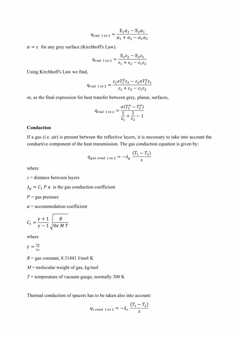
or, as the final expression for heat transfer between grey, planar, surfaces,
q;<= 4 >? 5 =𝜎 𝑇4C − 𝑇5C1𝜀4+ 1𝜀5− 1
Conduction
If a gas (i.e. air) is present between the reflective layers, it is necessary to take into account the conductive component of the heat transmission. The gas conduction equation is given by:
𝑞E<F G?H= 4 >? 5 = −𝜆E 𝑇4 − 𝑇5𝑠
where
s = distance between layers
𝜆E = 𝐶4 𝑃 𝑎 is the gas conduction coefficient
𝑃 = gas pressure
𝑎 = accommodation coefficient
𝐶4 =𝛾 + 1𝛾 − 1
𝑅8𝜋 𝑀 𝑇
where
𝛾 = GQGR
R = gas constant, 8.31441 J/mol·K
M = molecular weight of gas, kg/mol
T = temperature of vacuum gauge, normally 300 K
Thermal conduction of spacers has to be taken also into account:
𝑞F G?H= 4 >? 5 = −𝜆F 𝑇4 − 𝑇5𝑠

where 𝜆F = 𝐶5 𝑓 𝜆
𝐶5 = an empirical constant
𝑓 = relative density of the separator compared to solid material
𝜆 = separator material thermal conductivity, W/mK
The thermal conductivity inside each reflective layer can be neglected in reason of the extremely reduced thickness.
Now we consider a MLI composed of a number N of internal reflective layers, 𝑇T is the (hot) external surface and 𝑇U is the (cold) internal one. The total heat flux between the (i+1)-th and the i-th layer (Figure 4) is
𝑞>?> VW4 >? V = 𝑞;<= VW4 >? V + 𝑞E<F G?H= VW4 >? V + 𝑞F G?H= VW4 >? V
Figure 4: Thermal network of the MLI system.
The number of reflective gaps is N+1. For double metallized foils with identical emissivities on both sides the radiative heat transfer along the MLI thickness are (hp: each layer has a negligible thickness, so the metal coating of each layer has the same temperature):
𝑞;<= VW4 >? V =𝜎 𝑇VW4C − 𝑇VC
2𝜀 − 1
=𝜎𝜀 𝑇VW4C − 𝑇VC
2 − 𝜀 =𝜎𝜀 𝑇VW4C − 𝑇VC
2 − 𝜀 𝑇VW4 − 𝑇V𝑇VW4 − 𝑇V
The conductive flux is:
𝑞G?H= VW4 >? V = 𝜆E + 𝜆F 𝑇VW4 − 𝑇V
𝑠
The total heat flux through each gap is:

𝑞>?> VW4 >? V =𝜎𝜀 𝑇VW4C − 𝑇VC
2 − 𝜀 𝑇VW4 − 𝑇V𝑇VW4 − 𝑇V +
𝜆E + 𝜆F 𝑠 𝑇VW4 − 𝑇V
The heat flux through each gap has to be the same:
𝑞 =𝜎𝜀 𝑇TC − 𝑇YC
2 − 𝜀 +𝜆E + 𝜆F
𝑠 𝑇T − 𝑇Y =𝜎𝜀 𝑇YC − 𝑇Y94C
2 − 𝜀 +𝜆E + 𝜆F
𝑠 𝑇Y − 𝑇Y94
=𝜎𝜀 𝑇Y94C − 𝑇Y95C
2 − 𝜀 +𝜆E + 𝜆F
𝑠 𝑇Y94 − 𝑇Y95 = ⋯
=𝜎𝜀 𝑇4C − 𝑇UC
2 − 𝜀 +𝜆E + 𝜆F
𝑠 𝑇4 − 𝑇U
If we consider the first equality and we add both members with −Z[\]^_`
59[− abWac \]^_
F
we obtain:
𝜎𝜀 𝑇TC − 𝑇Y94C
2 − 𝜀 +𝜆E + 𝜆F
𝑠 𝑇T − 𝑇Y94 = 2𝜎𝜀 𝑇YC − 𝑇Y94C
2 − 𝜀 + 2𝜆E + 𝜆F
𝑠 𝑇Y − 𝑇Y94
this means that:
𝜎𝜀 𝑇TC − 𝑇UC
2 − 𝜀 +𝜆E + 𝜆F
𝑠 𝑇T − 𝑇U
= 𝑁 + 1𝜎𝜀 𝑇VW4C − 𝑇VC
2 − 𝜀 + 𝑁 + 1𝜆E + 𝜆F
𝑠 𝑇VW4 − 𝑇V
or:
𝜎𝜀 𝑇VW4C − 𝑇VC
2 − 𝜀 𝑇VW4 − 𝑇V𝑇VW4 − 𝑇V +
𝜆E + 𝜆F 𝑠 𝑇VW4 − 𝑇V = 𝑞 =
=1
𝑁 + 1𝜎𝜀 𝑇TC − 𝑇UC
2 − 𝜀 𝑇T − 𝑇U+
𝜆E + 𝜆F 𝑠 𝑇T − 𝑇U
We can introduce an effective conductivity 𝜆eff as:
𝑞T >? U = 𝜆eff 𝑇T − 𝑇U𝑁 + 1 𝑠
where:
𝜆eff =𝑠𝜎𝜀 𝑇TC − 𝑇UC
2 − 𝜀 𝑇T − 𝑇U+ 𝜆E + 𝜆F
and an effective emissivity 𝜀eff as:
𝜀eff =𝜀
𝑁 + 1 2 − 𝜀
The effective conductivity is temperature dependent 𝑇T, 𝑇U .

During the previous calculation we hypothesized that the emissivity 𝜀 was constant. In general, 𝜀 is temperature dependent. The emissivity of the aluminium film is:
𝜀hi = 6.3 109C𝑇5n
At room temperature 𝜀hi ≅ 0.028.
Each gap has a different emissivity because the temperature is different and the calculation of the flux is difficult.
We can take an approximate account of such dependency in this way: the influence of boundary temperatures is combined with the temperature dependency of previous equation. So the exponent of the temperature in the radiation term becomes 4+2/3=4.67
𝜆eff =𝑠𝜎 6.3 109C 𝑇TC.pq − 𝑇UC.pq
2 𝑇T − 𝑇U − 6.3 109C 𝑇T4.pq − 𝑇U4.pq+ 𝜆E + 𝜆F
This is just an approximation because in reality each layer has a different emissivity.
Example
An example of MLI is composed of an outer cover in Kapton with aluminium backing, an inner cover in aluminized polyimide with fiberglass backing, interior layers in aluminized Kapton, and separator layers in Dacron web. The material’s properties are reported in following table.
Thickness (mm) Absorbance 𝛼 Emissivity 𝜀 Temperature range min/max (°C)
Outer cover 0.127 0.54 (solar) 0.81 (IR) -73/+65
Inner cover 0.01 0.04
Interior layers 0.025 0.12 0.028 -250/+288 (intermittent)
Separators layers 0.16 - - -70/+177 (intermittent)
0.01
0.015
0.02
0.025
0.03
0.035
0.04
100 150 200 250 300 350 400 450
Emiss
ivity
Temperature (K)