Embed Size (px)
Citation preview

1
OPERATION AND INSTALLATION MANUAL
Multi-fuel and SE models
Woodland
Woodland Logstore
Guide d’utilisation et Mode d'Emploi
ENG/FR
February 2016
2
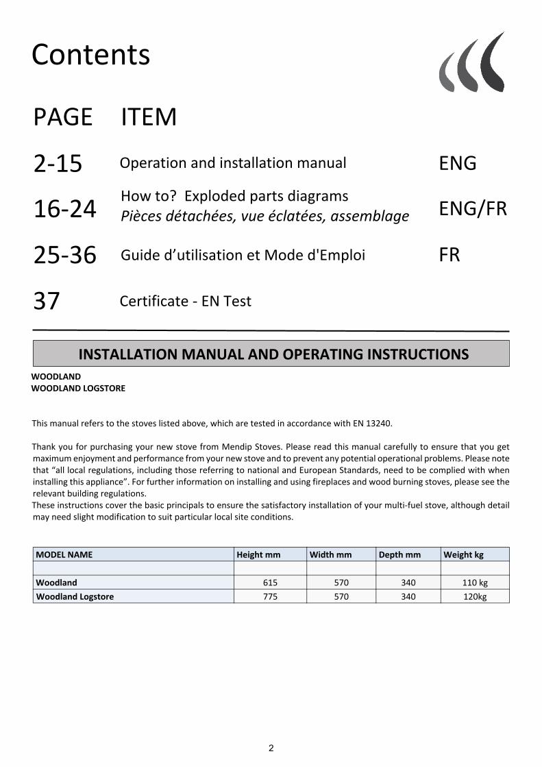
Contents
ITEMPAGE
WOODLANDWOODLAND LOGSTORE
This manual refers to the stoves listed above, which are tested in accordance with EN 13240.
Thank you for purchasing your new stove from Mendip Stoves. Please read this manual carefully to ensure that you getmaximum enjoyment and performance from your new stove and to prevent any potential operational problems. Please notethat “all local regulations, including those referring to national and European Standards, need to be complied with wheninstalling this appliance”. For further information on installing and using fireplaces and wood burning stoves, please see therelevant building regulations.These instructions cover the basic principals to ensure the satisfactory installation of your multi-fuel stove, although detailmay need slight modification to suit particular local site conditions.
MODEL NAME Height mm Width mm Depth mm Weight kg
Woodland 615 570 340 110 kg Woodland Logstore 775 570 340 120kg
Operation and installation manual ENG2-15
Guide d’utilisation et Mode d'Emploi
How to? Exploded parts diagramsPièces détachées, vue éclatées, assemblage ENG/FR
FR
16-24
25-36
INSTALLATION MANUAL AND OPERATING INSTRUCTIONS
Certificate - EN Test37

3
IMPORTANT:These instructions cover the basic principles to ensure the satisfactory installation of Mendip Stovesproduct :- Woodland models, although detail may need slight modification to suit particular local siteconditions.In all cases the installation must comply with current Building Regulations, Local Authority Byelaws andother specifications or regulations as they affect the installation of the stove. It should be noted that theBuilding Regulations requirements may be met by adopting the relevant recommendations given in BritishStandards BS 8303, BS EN 15287 as an alternative means to achieve an equivalent level of performance tothat obtained following the guidance given in Approved Document J.
—----------------------------------------------------------------------------------------------------------------------------------------------------------------INFORMATION FOR THE USER, INSTALLER AND SERVICE ENGINEER
—----------------------------------------------------------------------------------------------------------------------------------------------------------------Special care must be taken when installing a stove such that the requirements of the Health & Safety at Work Act are met.
HandlingAdequate facilities must be available for loading, unloading and site handling.
Fire CementSome types of fire cement are caustic and should not be allowed to come into contact with the skin. In case of contactwash immediately with plenty of water.
PREPARATORY WORK AND SAFETY CHECKS
IMPORTANT WARNINGThis stove must not be installed into a chimney that serves any other heating appliance. There must not be an extractorfan fitted in the same room as the stove because this can cause the stove to emit fumes into the room.
AsbestosThis stove contains no asbestos. If there is a possibility of disturbing any asbestos in the coarse of installation then pleaseseek specialist guidance and use appropriate protective equipment.
Metal PartsWhen installing or servicing this stove care should be taken to avoid the possibility of personal injury.
CO Alarms:-Building regulations require that whenever a new or replacement fixed solid fuel or wood/biomass appliance is installed ina dwelling a carbon monoxide alarm must be fitted in the same room as the appliance. Further guidance on theinstallation of the carbon monoxide alarm is available in BS EN 50292:2002 and from the alarm manufacturer’sinstructions.
Provision of an alarm must not be considered a substitute for either installing the appliance correctly or ensuringregular servicing and maintenance of the appliance and chimney system.
Stove paint AerosolsPaint aerosols are flammable and therefore dangerous to use around a lit stove. Be sure to allow aerosols spray paintsto dry and ventilate the room well before lighting the stove. The use of any aerosol around lit stove is dangerous andcare must be take in handling aerosols.
HEALTH AND SAFETY PRECAUTIONS

4
The outlet from the chimney should be above the roof of the building in accordance with the provisions of BuildingRegulations Approved Document J. If installation is into an existing chimney then it must be sound and have no cracks orother faults which might allow fumes into the house. Older properties, especially, may have chimney faults or the crosssection may be too large .
Mendip Stoves recommend the use of a solid fuel flue lining system for all installation into existing chimneys. All chimneysystems must be used in accordance with Building Regulations Approved Document J.
If an existing chimney is used the chimney must be clear of obstruction and be swept clean immediately before installationof the stove. The chimney should be tested to confirm the chimney will provide the correct chimney pressure for the stove.If the stove is fitted in place of an open fire the chimney should be swept one month after installation to clear any soot fallswhich may have occurred due to the difference in combustion between the stove and the open fire. If there is no existingchimney then either a prefabricated block chimney in accordance with Building Regulations Approved Document J or a twinwalled insulated stainless steel flue to BS 1856-1 . These chimneys must be fitted in accordance with the manufacturer’sinstructions and Building Regulations. A single wall metal flue pipe is suitable for connecting the stove to the chimney butis not suitable for using for the complete chimney. The chimney and connecting flue pipe must have a minimum diameterof 150 mm and its dimension should be not less than the size of the outlet socket of the stove. Any bend in the chimney orconnecting flue pipe should not exceed 45°. 90° bends should not be used other than within 150 mm of stove rear flueoutlet.
FLUE & CHIMNEY CONNECTION TO STOVE
Tested Gas flow rates fluegas temperatures
Flue gas flow rateWood /coal
Test flue gas temperaturewood /coal @ pascals of pressure
Woodland 4.7/4.3 g/sec 231/221deg C 12 pa
Chimney ConnectionIn order for the stove to perform satisfactorily the chimney height must be sufficient to ensure an adequatedraught to clear the products of combustion and prevent smoke problems into the room.
A chimney height of not less than 4.5 metres measured vertically from the outlet of the stove to the top of the chimneyshould be satisfactory. Alternatively the calculation procedure given in BS5854:1980 may be used as the basis for decidingwhether a particular chimney design will provide sufficient draught.
If it is found that there is excessive draught in the chimney then either an adjustable flue damper or alternately a draughtstabiliser should be fitted. The adjustable flue damper should not close off the flue entirely but should in its closed positionleave a minimum continuous opening free area of at least 20 % of the total cross sectional area of the flue or flue pipe.Adequate provision e.g. easily accessible soot door or doors must be provided for sweeping the chimney and connecting fluepipe.
Your appliance needs to be maintained routinely, the throat plate/baffle should be cleaned regularly (monthly) . The fluepipe can be cleaned using a flexible brush. Only Use a dry cloth on external surfaces. Over time the glass may become dirty,clean with a damp cloth and polish off with damp cloth. If the stove has not been used for some time the flue should bechecked for blockages before use. Do not modify the appliance; only use spares authorised by the manufacturer.
5
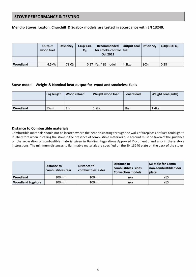
Log length Wood reload Weight wood load Coal reload Weight coal (anth)
Woodland 35cm 1hr 1.2kg 2hr 1.4kg
Outputwood fuel
Efficiency CO@13%O₂
Recommendedfor smoke control
Oct 2012
Output coalfuel
Efficiency CO@13% O₂
Woodland 4.5kW 79.0% 0.17 Yes / SE model 4.2kw 80% 0.28
STOVE PERFORMANCE & TESTING
Distance to Combustible materialsCombustible materials should not be located where the heat dissipating through the walls of fireplaces or flues could igniteit. Therefore when installing the stove in the presence of combustible materials due account must be taken of the guidanceon the separation of combustible material given in Building Regulations Approved Document J and also in these stoveinstructions. The minimum distances to flammable materials are specified on the EN 13240 plate on the back of the stove
Distance tocombustibles rear
Distance tocombustbles sides
Distance tocombustibles sidesConvection models
Suitable for 12mmnon-combustible floorplate
Woodland 100mm 100mm n/a YES Woodland Logstore 100mm 100mm n/a YES
Mendip Stoves, Loxton ,Churchill & Sqabox models are tested in accordance with EN 13240.
Stove model Weight & Nominal heat output for wood and smokeless fuels

6
Distance from
Height Width Depth Collarsize
rear to centreflue collar
Floor to rear fluestove/ logstore
Back to airconnection
Floor to air intakestove/logstore
A B C D E F G H
Woodland 615mm 570mm 340mm 125mm 130mm 523mm 75mm 50mm
WoodlandLogstore 775mm 570mm 340mm 125mm 130mm 683mm 75mm 210mm
A F
E
CB
D
G
H
135 I
I
JJ
212
223,5
116°
210
131 260
387
75
473
250
I-I 1 : 5
425
223
,5
490 J-J 1 : 5
265
Kreslil:
Materiál: Polotovar:
Název:
Č. výkresu Formát listu:Měřítko: List:
A3 5z51:10
Schválil dne:Schválil:
28.8.2014Kreslil dne:
107277.88Hmotnost:
Změnil dne :Změnu schválil:
Popis změny:
A-10Oprava:
4051Sestava_EST_4051_000_1
Martin Schejbal©2012-2015 EUROTRADINGGROUP s.r.o.Josefská 6A, Rumburk,40801, ČRičo:28721446
všechny ostré hrany odjehlit, svary očistit pokud není na výkrese uvedeno jinak, dokument se řídí normami : ISO 2768-1-2 (m), EN 22553, ISO 7200, ISO 16016
index změny :
držitel práv :
chráněno dle ISO 16016
Tato dokumentace je nehmotným vlastnictvím poskytovatele, jakékoli kopírování, či poskytnutí třetím osobám je zakázáno bez souhlasu poskytovatele.
EUROTRADINGGROUP s.r.o.
STOVE DIMENSIONS AND CONNECTION MEASUREMENTS
Dimension H is when additional item “closed combustion rear inlet adapter “(M90500-13-00-00-00) is fitted.
For rear inlet connection a closed combustion rear inlet adapter is needed.
78,
8
66
nátrubek lepit
5
4
3
21
Poz. Číslo výkresu Název Materiál Polotovar Konfigurace Kusů
1 EST_050_020_02_0 deska 1.0038 (S235JRG2) Plech 1,50 mm Laser -0 1
2 EST_050_020_01_0 hrdlo 1.0038 (S235JRG2) Plech 1 mm Laser -0 1
3 EST_050_020_03_0 tělo 1.0038 (S235JRG2) Plech 1,50 mm Laser -0 1
4 ILU_80_lindab hrdlo LINDAB ILU 80mm
Materiál <není určen>
nákup LINDAB : ILU 80 -0 1
5 EST_050_020_04_0 držák 1.0038 (S235JRG2) Plech 1,50 mm Laser -0 1
Kreslil:
Materiál: Polotovar:
Název:
Č. výkresu Formát listu:Měřítko: List:
A3 1z21:2
Schválil dne:Schválil:
7.12.2012Kreslil dne:
813.70Hmotnost:
Změnil dne :Změnu schválil:
Popis změny:
Oprava:
nátrubek externího vzduchu 5,6 KWSestava_EST_050_020_0
Martin Schejbal 2012 EUROTRADINGGROUP s.r.o.
autorská práva vyhrazena
všechny ostré hrany odjehlit, svary očistit pokud není na výkrese uvedeno jinak, dokument se řídí normami : ISO 2768-1-2 (m), EN 22553, ISO 7200, ISO 16016
index změny :
držitel práv :
chráněno dle ISO 16016
AA
po svaření zabrousit do roviny pod barvu
z3 135
z3 135
135
135
A-A
z3 135
135
135
z3 4x15(90°)135
Kreslil:
Materiál: Polotovar:
Název:
Č. výkresu Formát listu:Měřítko: List:
A3 2z21:2
Schválil dne:Schválil:
7.12.2012Kreslil dne:
813.70Hmotnost:
Změnil dne :Změnu schválil:
Popis změny:
Oprava:
nátrubek externího vzduchu 5,6 KWSestava_EST_050_020_0
Martin Schejbal 2012 EUROTRADINGGROUP s.r.o.
autorská práva vyhrazena
všechny ostré hrany odjehlit, svary očistit pokud není na výkrese uvedeno jinak, dokument se řídí normami : ISO 2768-1-2 (m), EN 22553, ISO 7200, ISO 16016
index změny :
držitel práv :
chráněno dle ISO 16016

7
In order for the stove to perform efficiently and safely there should be an adequate air supply into the room in which thestove is installed to provide combustion air. This is particularly necessary if the room is double-glazed or a flue draughtstabiliser is operating in the same room as the appliance. The provision of air supply to the stove must be in accordance withcurrent Building Regulations Approved Document J. An opening window is not appropriate for this purpose. Air inlets mustbe positioned in such a way that they cannot be blocked. An air inlet may be a vent (the vent must be open and the capacityfor the vent sufficient when the stove is lit) .
There are no European rules regarding the minimum distance to non-flammable walls, Mendip Stoves recommend leavinga gap of at 100mm behind and to sides of stove.
The Woodland models take all combustion from a single 80mm port under the stove, with the door closed the air portsupplies all combustion air for the appliance. This can be connected to the outside via a 80mm pipe so the appliance doesnot draw air from the room. However Mendip stoves still recommends the use of an air brick as laid out in document j forwhen the stove is being reloaded.
The hearth should be able to accommodate the weight of the stove and its chimney if the chimney is not independentlysupported. The Woodland stoves have been tested and are suitable to be installed on a 12 mm non combustible plate suchas 12 mm glass plates . Installation of all hearths should comply in size and construction so that it is in accordance with theprovisions of the current Building Regulations Approved Document J.The clearance distances to combustible material beneath, surrounding or on the hearth and walls adjacent to the hearthshould comply with the guidance on the separation of combustible material given in Building Regulations Approved DocumentJ and also in these stove instructions.If the stove is to be installed on a wooden floor, it must be covered with a non-combustible material at least 12 mm thick,in accordance with Building Regulations Approved Document J, to a distance of 30 cm in front of the stove and 15 cm toeach side measuring from the door of the combustion chamber.
HEARTH
COMBUSTION AIR
COMBUSTION CHAMBERS
Mendip Stoves are fitted internally with vermiculite heat deflection panels and baffles, these panels are designed to ensurethe maximum efficiency and are an integral part of the clean burn process of the stove. These baffles should not be removedother than for cleaning the stove. Any defective panels should be replaced, (small hairline cracks do not need replacement)however can develop during long term use to a larger crack, if this passes through the vermiculte to the stove body then thepanel must be replaced. When refuelling your stove place the wood fuel into the chamber (wearing a glove), impact fromlogs can cause the heat deflection panel to crack.Connection to chimneyMendip Stoves are built with a top flue outlet as standard, this can be altered to a rear connection by removing the topcollar, rear cover plate then exchanging collar and plate. Care should be taken to ensure an airtight fit when refitting collarand plate. A decorative cover plate is included in each stove to cover the hole in the convection top plate. This collarallows connection to either a masonry chimney or a prefabricated factory made insulated metal chimney.
COMMISSIONING AND HANDOVER
Ensure all loose parts (bricks and grates) are fitted in accordance with the instructions given in the instruction booklet. Oncompletion of the installation allow a suitable period of time for any fire cement and mortar to dry out, a small fire may belit to check that smoke and fumes are taken from the stove up the chimney and emitted safely into the atmosphere. Do notrun at full output for at least 24 hours.On completion of the installation and commissioning ensure that the operating instructions for the stove are left with thecustomer. Ensure to advise the customer on the correct use of the appliance with the fuels likely to be used in the stove andnotify them to use only the recommended fuels for the stove. Advise the user what to do should smoke or fumes be emittedfrom the stove.
The customer should be warned to use a fireguard to BS 8423:2002 in the presence of children, aged and/or infirm persons.

8
OPERATING YOUR STOVE - THE WOODLAND
Suitable fuels
Your stove is tested to burn wood or registered smokeless coal. Wood briquettes can also be burnt but special accountshould be taken of fuel weight. For a full list of suitable fuels, check with the official solid fuels approvals body, HETAS orSolid Fuel Association. Do not overload stove as this can cause excessive heat and damage the stove (see table on page 5).
ALWAYS KEEP FUEL LOAD BELOW TERTIARY PORTS AT REAR OF STOVE. Only use fuels approved for use on heating stoves.Do not burn liquid fuels, drift wood, finished wood, sawn wood, pallet wood, chipboard/plywood ,varnished wood orplastic coated wood, wood treated with preservatives, or any house hold waste.
DO NOT EXCEED SPECIFIED FUEL WEIGHTS.DO NOT BURN HOUSE COAL. DO NOT BURN HOUSEHOLD WASTE, THIS APPLIANCE IS NOT
AN INCINERATOR.
MENDIP STOVES RECOMMEND THE USE OF A FLUE THERMOSTAT TO CHECK YOUR STOVE IS NOTOVERHEATING. PLACE FLUE THERMOSTAT DIRECTLY ABOVE COLLAR OF STOVE AND REFER TOTEMPERATURE GAUGE ON PAGE 4.
LIGHTING YOUR STOVE FOR THE FIRST TIME
Before lighting your stove for first time make sure you have read this manual fully and acquainted yourself with thecontrols of this appliance. (see page 9)
The heat-resistant paint on your stove will cure and harden the first time you light your appliance.
The curing process produces a good deal of smoke and odour, it is therefore important that the first time you light yourstove the room should be well ventilated.
During the process it is important to open and close the stove door periodically (every 30mins) during the first couple offirings therefore preventing the door seal cord around the door from sticking and coming away from the door. Once theheat-resistant paint has hardened the smell will disappear.
Your stove is NOT designed to be used with the door open, the stove door must be kept closed except when lighting thestove, adding firewood or removing ash in order to prevent flue gases from escaping.
Use of Fire lightersQuality Firelighters should be used when lighting your stove. (Never use mentholated spirit, petrol or other flammable liquids).Lighting your stove with firelighters will be more reliable and easier than using paper. Lighting your fire with paper resultsin excess smoke, more ash and possible blackening of glass.

9
OPERATING YOUR STOVE - THE WOODLAND- AIR CONTROLLER
The Universal air controller provides air control for the whole stove from a single control lever. The Lever has two keyoperationsMoving the control lever in and outSliding the control lever in reduces and out increases the total amount of combustion air in the stove.
Moving the control lever from left to rightBy moving the control lever to the left increases the primary air mix and moving to the right increases secondary air(airwash) mix .
Whatever position the control is set at, the lever can have either minimum combustion air or maximum combustion air.
More air pull out Less air push in
Left Primary air
Right Secondary air

10
Note: If the chimney is externally fitted or the stove has been installedon a larger diameter clay chimney liner then on cold days it maybenecessary to warm the flue using firelighters prior to lighting with wood.
1. Place a few smaller pieces of dry wood (kindling) in the stove on top ofthe non toxic firelighters, place one or two small dry split logs (¼ split) ontop. Kindling stacked as in diagram allows combustion air flow freely andwill aid ignition.
2. Fully slide open (pull out ) the Universal air control (UAC) air slider belowthe stove door. Slide out fully to the middle position. The stove now hasa mix of primary air secondary air for start up.
Light the firelighters and push door to closed position, latch in 1st positionso the door is open 2 mm. (see picture) This provides additionalcombustion air for start up and reduces condensation on the door glass.It maybe necessary to open the ash pan a small amount( 1-2 mm) to allowmore air if the chimney is slow.
4. Once the flames from the logs are fully established , this can take up to10 min's . The door can now be closed. Leave the UAC control in the middleposition (if the slider is in the middle the air controller is providing equalprimary and secondary air).If the stove flames begin to falter and generatesmoke in chamber unlatch the door again until the fire is established.
6. Once the fire bed is established slide UAC control to the secondaryposition and push in slider by 25%, forthe stove to burn cleanly plenty ofsecondary air is needed, do not betempted to shut the fire down too earlyas this may cause smoke. At nominalheat output, expect to refuel your stoveapproximately once an hour. Check loadweights for your model on the table onpage 5.use the glove when operating air controls and door.
HOW TO LIGHT YOUR WOODBURNING STOVE
The stove will get very hot during use and due care must therefore be exercised.Please use the glove when operating air controls , door and ashpan.
WOOD FUELGood quality wood is the most important factor in your stove working efficiently and cleanly. Always use dry split hardwoodfirewood (moisture content of 20% or less). The dryness of the firewood plays an important role since the use of wet woodresults in poor fuel economy and may cause a tarry sooty film on the internals of the stove.Newly cut wood contains 60–70% water, making it totally unsuitable for use as firewood.Newly cut wood should be stacked and air dried under cover for two years before being used as firewood.Do not burn liquid fuels, drift wood, finished, sawn wood, pallet wood, chipboard/plywood, varnished wood or plasticcoated wood, wood treated with preservatives, or house hold waste.
11
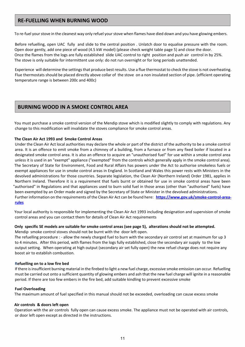
You must purchase a smoke control version of the Mendip stove which is modified slightly to comply with regulations. Anychange to this modification will invalidate the stoves compliance for smoke control areas.
The Clean Air Act 1993 and Smoke Control AreasUnder the Clean Air Act local authorities may declare the whole or part of the district of the authority to be a smoke controlarea. It is an offence to emit smoke from a chimney of a building, from a furnace or from any fixed boiler if located in adesignated smoke control area. It is also an offence to acquire an "unauthorised fuel" for use within a smoke control areaunless it is used in an "exempt" appliance ("exempted" from the controls which generally apply in the smoke control area).The Secretary of State for Environment, Food and Rural Affairs has powers under the Act to authorise smokeless fuels orexempt appliances for use in smoke control areas in England. In Scotland and Wales this power rests with Ministers in thedevolved administrations for those countries. Separate legislation, the Clean Air (Northern Ireland) Order 1981, applies inNorthern Ireland. Therefore it is a requirement that fuels burnt or obtained for use in smoke control areas have been
"authorised" in Regulations and that appliances used to burn solid fuel in those areas (other than "authorised" fuels) havebeen exempted by an Order made and signed by the Secretary of State or Minister in the devolved administrations.Further information on the requirements of the Clean Air Act can be found here: https://www.gov.uk/smoke-control-area-rules
Your local authority is responsible for implementing the Clean Air Act 1993 including designation and supervision of smokecontrol areas and you can contact them for details of Clean Air Act requirements
Only specific SE models are suitable for smoke control areas (see page 5), alterations should not be attempted.Mendip smoke control stoves should not be burnt with the door left open.The refuelling procedure : - allow the newly charged fuel to burn with the secondary air control set at maximum for up 3to 4 minutes. After this period, with flames from the logs fully established, close the secondary air supply to the lowoutput setting. When operating at high output (secondary air set fully open) the new refuel charge does not require anyboost air to establish combustion.
Refuelling on to a low fire bedIf there is insufficient burning material in the firebed to light a new fuel charge, excessive smoke emission can occur. Refuellingmust be carried out onto a sufficient quantity of glowing embers and ash that the new fuel charge will ignite in a reasonableperiod. If there are too few embers in the fire bed, add suitable kindling to prevent excessive smoke
Fuel OverloadingThe maximum amount of fuel specified in this manual should not be exceeded, overloading can cause excess smoke
Air controls & doors left openOperation with the air controls fully open can cause excess smoke. The appliance must not be operated with air controls,or door left open except as directed in the instructions.
RE-FUELLING WHEN BURNING WOOD
BURNING WOOD IN A SMOKE CONTROL AREA
To re-fuel your stove in the cleanest way only refuel your stove when flames have died down and you have glowing embers.
Before refuelling, open UAC fully and slide to the central position . Unlatch door to equalise pressure with the room.Open door gently, add one piece of wood (4.5 kW model) (please check weight table page 5) and close the door.Once the flames from the logs are fully established slide UAC control to right position and push air control in by 25%.The stove is only suitable for intermittent use only: do not run overnight or for long periods unattended.
Experience will determine the settings that produce best results. Use a flue thermostat to check the stove is not overheating.Flue thermostats should be placed directly above collar of the stove on a non insulated section of pipe. (efficient operatingtemperature range is between 200c and 400c)

12
Note: on cold days it maybe necessary to warm the flue using two firelighters.
1. Place Firelighters and a few smaller pieces of dry wood (kindling) among a small quantity of fuel in the combustionchamber.
2. Fully slide open (pull out fully) the Universal air control (UAC) air slider below the stove door. Slide fully to the leftposition. The stove now has total primary air for start up. (It maybe necessary to pull open ash pan 2 mm in someconditions.). Light firelighters and securely close door.
3. With the fire established, open the door. And fill chamber with fuel, (see weight table on page 3) do not overload. (donot cover tertiary air ports). Reloading is approximately every hour.
4. Close fire door, set UAC control to mainly primary and 80% open.5. Adjust as necessary.
Re-fueling solid fuel
To re-fuel your stove.Before refuelling, open UAC control to primary and fully open.Open door gently and de -ash your stove with use of poker. (not provided)Add fuel to below tertiary air bar (see weight table on page 3) and close the door.
Leave the air controls open whilst fuel is established.Once established set UAC control to mainly primary and 80% open.
In the event of a chimney fire: Close the air controls and the stove door, and call 999 or your local fire brigade.If your stove is overheating close all air sliders and door , leave until the stove has returned to normal temperature.The stove is only suitable for intermittent use only: do not run overnight or for long periods unattended.
Experience will determine the settings that produce best results. Use a flue thermostat to check the stove is not overheating.Flue thermostats should be placed directly above collar of the stove on a non insulated section of pipe. (efficient operatingtemperature range is between 100c and 200c) The stove will get very hot during use and due care must therefore be exercised.Please use the glove and operating tool supplied when operating air controls and door.
SOLID SMOKELESS FUELS-Loxton, Churchill & Sqabox models are suitable for use with good quality smokeless fuels and have been fully tested to therelevant European standard. Only use registered smokeless fuels on this stove. Take special note of load quantities in frontof this book.(page 5)
HOUSE COAL AND PETROLEUM COKE ARE NOT SUITABLE FOR USE ONTHIS STOVE; ITS USE WILL INVALIDATE THE GUARANTEE.
LIGHTING THE STOVE - SOLID FUELS

13
If the air controls on your stove are closed too much incomplete combustion may lead to a build-up of hard, shiny soot onthe inside of your stove and glass. To prevent sooting of the chamber and glass introduce:-
1) more secondary air,2) check that your fuel is suitable and dry.3) that you have sufficient draw in your chimney.
It is important to check the draft conditions before lighting your stove. This may be done, for instance, by crumpling a pieceof newspaper, placing it in the combustion chamber and lighting it. The draft conditions are good if the smoke is drawn awaythrough the chimney.
INCOMPLETE COMBUSTION
Mendip stoves do not recommend burning registered smokeless coal in a slumbering position, Mendip stoves are designedto burn wood and quality registered smokeless fuels. Wood burns more efficiently and cleanly if it is burnt hotter. Mendipstoves do not recommend that their stoves are burnt overnight for this reason. As a night time regime we recommend thatthe fire is loaded when hot and burnt for five minutes with the secondary air control fully open until the new wood has takenand is burning, then close the secondary air valve to its operational position. On returning to the stove in the morning thefire will have burn out, reload with some paper or firelighter and some kindling and open both air sliders fully to relightquickly. Beware as the ash bed will have hot embers.
OVERNIGHT BURNING
PERMANENT AIR VENT
The stove requires a permanent air vent to the room . This is to provide adequate air supply in order for the stove to operatesafely and efficiently. In accordance with current Building Regulations the installer may have fitted a permanent air supplyvent into the room in which the stove is installed to provide combustion air. This air vent should not under any circumstancesbe shut off or sealed.

14
Properly installed, operated and maintained this stove will not emit fumes into the dwelling. Occasional fumes fromde-ashing and re-fuelling may occur. However, persistent fume emission is potentially dangerous and must not betolerated. If fume emission does persist, then the following immediate action should be taken:-
(a) Open doors and windows to ventilate the room and then leave the premises.(b) Let the fire go out.(c) Check for flue or chimney blockage and clean if required(d) Do not attempt to relight the fire until the cause of the fume emission has been identified and corrected. If necessary
seek expert advice.The most common cause of fume emission is flue way or chimney blockage. For your own safety these must be kept cleanat all times.
CO AlarmYour installer should have fitted a CO alarm in the same room as the appliance. If the alarm sounds unexpectedly, followthe instructions given under “Warning Note” above.
AerosolsAerosols are flammable and therefore dangerous to use around a lit stove. Do not use aerosols sprays near your lit stove.The use of any aerosol is dangerous and care must be take in handling aerosols.
1. Fire Will Not Burn - checka) the air inlet is not obstructed in any way,b) that chimney and flue ways are clear,c) that a suitable fuel is being used,d) that there is an adequate air supply into the room,e) that an extractor fan is not fitted in the same room as
the fire.
2. Fire Blazing Out Of Control - checka) the doors are tightly closed,b) the air controls are turned down to the minimum
setting,c) the flue damper is closed ( if fitted),d) a suitable fuel is being used,e) the door seals are in good condition.F) the chimney draft may be too strongG) check ash pan seal andH) check for ash below ash pan causing pan to seat
incorrectly and clean out.
3) Soot forms on the windowa) The firewood may be too wetb) the intake of secondary air may be insufficientc) fire not hot enough
4) The stove fails to heat fullya) The firewood may be too wetb) the intake of secondary air may be insufficient
5) Smoke or odoura) weak chimney draftb) check for blockages in the flue pipe/chimneyc) check the height of the chimney relative to the
surroundings
6) Soot in the chimneya) The firewood may be too wetb) intake of secondary air may be insufficient
These appliances have been approved by HETAS Ltd as an intermittent operating appliance for burning both wood and smokelessfuels only.
HETAS recommended fuels:Please note that HETAS Ltd Appliance Approval only covers the use of wood logs and approved smokeless fuels on this appliance.HETAS Ltd Approval does not cover the use of other fuels either alone or mixed with the recommended fuels listed above, nordoes it cover instructions for the use of other fuels.
WARNING NOTE
HETAS LTD APPROVAL
TROUBLE SHOOTING
15
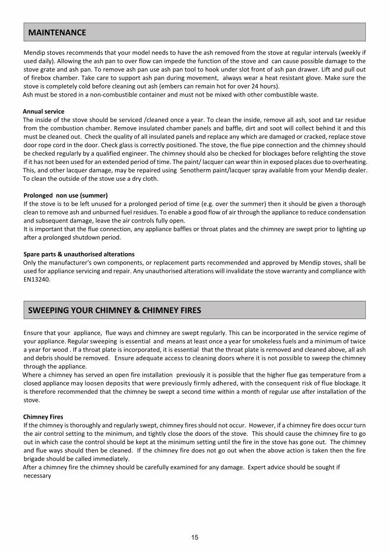
Ensure that your appliance, flue ways and chimney are swept regularly. This can be incorporated in the service regime ofyour appliance. Regular sweeping is essential and means at least once a year for smokeless fuels and a minimum of twicea year for wood . If a throat plate is incorporated, it is essential that the throat plate is removed and cleaned above, all ashand debris should be removed. Ensure adequate access to cleaning doors where it is not possible to sweep the chimneythrough the appliance.Where a chimney has served an open fire installation previously it is possible that the higher flue gas temperature from aclosed appliance may loosen deposits that were previously firmly adhered, with the consequent risk of flue blockage. Itis therefore recommended that the chimney be swept a second time within a month of regular use after installation of thestove.
Chimney FiresIf the chimney is thoroughly and regularly swept, chimney fires should not occur. However, if a chimney fire does occur turnthe air control setting to the minimum, and tightly close the doors of the stove. This should cause the chimney fire to goout in which case the control should be kept at the minimum setting until the fire in the stove has gone out. The chimneyand flue ways should then be cleaned. If the chimney fire does not go out when the above action is taken then the firebrigade should be called immediately.After a chimney fire the chimney should be carefully examined for any damage. Expert advice should be sought ifnecessary
Mendip stoves recommends that your model needs to have the ash removed from the stove at regular intervals (weekly ifused daily). Allowing the ash pan to over flow can impede the function of the stove and can cause possible damage to thestove grate and ash pan. To remove ash pan use ash pan tool to hook under slot front of ash pan drawer. Lift and pull outof firebox chamber. Take care to support ash pan during movement, always wear a heat resistant glove. Make sure thestove is completely cold before cleaning out ash (embers can remain hot for over 24 hours).Ash must be stored in a non-combustible container and must not be mixed with other combustible waste.
Annual serviceThe inside of the stove should be serviced /cleaned once a year. To clean the inside, remove all ash, soot and tar residuefrom the combustion chamber. Remove insulated chamber panels and baffle, dirt and soot will collect behind it and thismust be cleaned out. Check the quality of all insulated panels and replace any which are damaged or cracked, replace stovedoor rope cord in the door. Check glass is correctly positioned. The stove, the flue pipe connection and the chimney shouldbe checked regularly by a qualified engineer. The chimney should also be checked for blockages before relighting the stoveif it has not been used for an extended period of time. The paint/ lacquer can wear thin in exposed places due to overheating.This, and other lacquer damage, may be repaired using Senotherm paint/lacquer spray available from your Mendip dealer.To clean the outside of the stove use a dry cloth.
Prolonged non use (summer)If the stove is to be left unused for a prolonged period of time (e.g. over the summer) then it should be given a thoroughclean to remove ash and unburned fuel residues. To enable a good flow of air through the appliance to reduce condensationand subsequent damage, leave the air controls fully open.It is important that the flue connection, any appliance baffles or throat plates and the chimney are swept prior to lighting upafter a prolonged shutdown period.
Spare parts & unauthorised alterationsOnly the manufacturer's own components, or replacement parts recommended and approved by Mendip stoves, shall beused for appliance servicing and repair. Any unauthorised alterations will invalidate the stove warranty and compliance withEN13240.
MAINTENANCE
SWEEPING YOUR CHIMNEY & CHIMNEY FIRES

16
Always use the operating tools provided whenhandling parts likely to be hot when the stove isin use. Your stove has the following parts inthe stove.
1. Cast Iron grate & log retainer2. Ashpan3. Stove Glove4. Top plate decorative cover plate5. Instruction manual & warranty card6. Vermiculite brick linings ( these are integral
to the stoves performance-Do not throwaway)
7. Moisture absorbency bag
LOOSE PARTS / PIÈCES DÉTACHÉES
STOVE PARTS, COMBUSTION CHAMBER, ASSEMBLYPIÈCES DÉTACHÉES, VUE ÉCLATÉES
1. Grille en fonte et arrêt de bûches3. Bac à cendre4. Gant5. Plaque de décor6. Guide d’utilisation et bon de garantie7. Briques réfractaires, elles font partie intégrante du poêle, nepas jeter.8. Sac absorbant d’humidité
Toujours utiliser les outils prévus pour manipulerles pièces susceptibles d'être chaudes lorsque lepoêle est en cours d'utilisation. Votre poêlecomprend les éléments suivants dans le poêle.
"This section shows the parts contained in your stove, each stove has over 80 spare-parts and, each part is detailed. Whennew parts are required the section will allow spares to be recognised and ordered. As a further source of referenceplease visit www.eurostove.co.uk for latest spare-part information.
Cette section montre les pièces contenues dans votre poêle, chaque poêle a plus de 80 pièces de rechange et, chaqueélément est détaillée. Lorsque de nouvelles pièces doivent la section permettra aux pièces de rechange d'être reconnuset ordonné. Comme autre source de refernece s'il vous plaît visiter pour www.eurostove.co.uk dernières informationspièce de rechange.
17
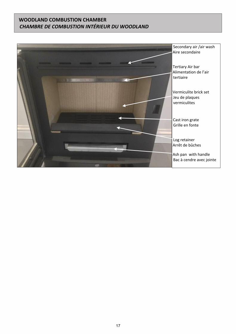
Secondary air /air washAire secondaire
Tertiary Air barAlimentation de l’airtertiaire
Vermiculite brick setJeu de plaquesvermiculites
Cast iron grateGrille en fonte
Log retainerArrêt de bûches
Ash pan with handleBac à cendre avec jointe
WOODLAND COMBUSTION CHAMBERCHAMBRE DE COMBUSTION INTÉRIEUR DU WOODLAND

18
HOW TO REMOVE A VERMICULITE BRICK SETMONTAGE ET DÉMONTAGE DE L’INTÉRIEUR
To remove a vermiculite brick set take the following steps
Pour enlever un ensemble de briques vermiculites suivez les étapes
Remove ashpan and log retainer
Enlever le bac à cendre et l’arrêt de bûches
Place hand through ashpan and lift the cast iron grate up and forward torest on the front edge of the stove. Remove back right vermiculite panel bypulling out in the middle and sliding out to the left.
Placez la main à travers cendrier et soulevez la grille en fonte à l'avant dupoêle.Retirez le panneau de vermiculite arrière droit en tirant au milieu et enfaisant glisser vers la gauche.
Having removed rear right brick, Rotate grate so rear of the grate is facingupwards.
Après avoir enlevé la brique arrière droite, tourner la grille de sorte quel'arrière de la grille est orientée vers le haut.
Turn grate so side is pushed in rear right corner beyond side brick, Lift grateout of stove.
Tournez la grille afin que le côté reste poussé dans le coin arrière droit dansla position de la brique de côté. Ensuite, sortez la grille en fonte du poêle.
Take rear left brick out
Sortez le brique arrière gauche du poêle.

19
Remove side right brick baffle by sliding across to the at the way to the leftof the stove and pulling forward toward door.
Retirez le déflecteur de droite en glissant à gauche et en tirant en avant versla porte.
Remove side left brick by pushing up left baffle plate and then sliding sidebrick out.
Retirez le déflecteur de droite en glissant à travers la gauche du poêle et entirant en avant vers la porte.
Remove side left brick baffle brick by sliding to left and pulling forwardtowards door.
Retirer la brique latérale gauche en poussant le déflecteur gauche vers lehaute et puis en glissant la brique latérale vers la sortie du poêle.
Above the two vermiculite baffles are two steel baffle plates, these aresupported by the fire brick (baffle) /plate (steel) support bracket. To removelift right side plate up out of lug at the front and slide plate to the left. Slideback to right below supporting lugs and plate should now come down.
Remove right plate by lifting out of lug and sliding to the right until the platecome out.
To remove side right vermiculite brick, the rear tertiary air bar must beremoved, remove 4 nuts, and the brick will slide back and come out.
This leaves the chamber empty.
Au-dessus des deux déflecteurs vermiculite, vous retrouvez deux déflecteursen acier, Ces derniers sont tenus par le support central des déflecteursvermiculites et des supports latéraux. Soulevez le déflecteur en acier dedroite, levez le pied et sortez de la bride de support centrale, puis faitesglisser la plaque vers la gauche.
Enfin, faites glisser la plaque vers la droite au-dessous des pattes de supportlatérale et la plaque peut maintenant sortir.
Pour enlever le déflecteur acier gauche, levez le pied en place à partir de labride de support avant et glissez à droite jusqu'à ce qu'il soit passé, le soutienà gauche, faites glisser la plaque vers la gauche au-dessous des pattes desupport latérale puis retirez.
HOW TO REMOVE A VERMICULITE BRICK SETMONTAGE ET DÉMONTAGE DE L’INTÉRIEUR
20
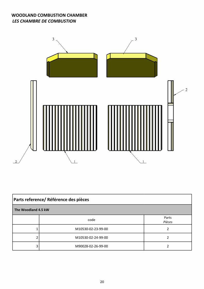
WOODLAND COMBUSTION CHAMBERLES CHAMBRE DE COMBUSTION
Parts reference/ Référence des pièces
The Woodland 4.5 kW
code PartsPièces
1 M10530-02-23-99-00 2
2 M10530-02-24-99-00 2
3 M90028-02-26-99-00 2
2
33

21
21
25
2
18
65281
27
8
7
24
26 11
22
23
27
17
28920
19
4 5
10
Poz. Číslo výkresu Název Materiál Polotovar Konfigurace Kusů1 Sestava_EST_4051_100_2 Komora
5kw_WIDE -0 1
2 EST_2051_000_01_0 rošt Kujná litina (temperovaná) odlitek -0 1
3 Sestava_EST_4051_010_1 vermeculit 5 KW -0 1
4 Sestava_EST_4051_400_0 sestva víko loxton -0 1
5 EST_2051_000_03_1 těsnění pod kouřovod
Materiál <není určen> šňůra 20x2 -0 2
6 EST_2051_000_04_2 záslepka kouřovodu
1.0038 (S235JRG2) 3x3000x1500 -0 1
7 Sestava_EST_050_000_6 NEW AIR SYSTEM -0 1
8 EST_2051_000_08_0 hadice sekundáru Guma
hadice 50mm teplota do
+100°C-0 1
9 EST_2051_000_10_2 čistící klapka 1.0038 (S235JRG2) 3x3000x1500 -0 1
10 EST_2051_000_11_1 kouřovod 125 Kujná litina (temperovaná) odlitek -0 1
11 EST_2051_000_09_0 hadice promáru
Materiál <není určen>
hadice 50mm teplota do
+100°C-0 1
12 EST_2051_000_16_0 izolační deska Materiál <není určen> -0 1
13 EST_2051_000_17_0 izolační deska Materiál <není určen> -0 1
14 Sestava_EST_4051_050_1 Pant spodní -0 1
15 Sestava_EST_4051_040_1 Pant vrchní -0 1
16 EST_4051_000_06_0 kroužekObchodní bronz, UNS
C22000 (90-10 bronz)
tyč 8h11 -0 1
17 Sestava_EST_4051_300_1 Sestava_ dveře _ WIDE -0 1
18 EST_4051_000_12_0 zábrana Kujná litina (temperovaná) odlitek -0 1
19 EST_2051_000_13_3 deflektor 1.0038 (S235JRG2) 5x3000x1500 -0 1
20 EST_2051_000_14_3 deflektor 1.0038 (S235JRG2) 5x3000x1500 -0 1
21 EST_2051_000_15_0 druhé stínění 1.0036 (S235JRG1)
Plech 1 mm Laser -0 1
22 EST_2051_000_05_1 terciál 1.4301 (X5CrNi18-10) 1,5x3000x1500 -0 1
23 EST_2051_000_06_1 těsnění terciál Materiál <není určen> šňůra 10x4 -0 1
24 EST_2051_000_07_3 spodní stínění 1.0036 (S235JRG1) 0,8x3000x1500 -0 1
25 EST_2051_000_02_1 zadní stínění 1.0036 (S235JRG1) 0,8x3000x1500 -0 1
26 EST_3052_000_02_1 tělo popelníku 1.0038 (S235JRG2)
Plech 0,80 mm Laser -0 1
27 EST_2056_000_17_0 druhé boční stínění
1.0036 (S235JRG1)
Plech 1 mm Laser -0 2
28 Sestava_EST_4051_070_0Dtžák
bočního stínění
-0 2
29 šroub_DIN_6921šroub s
ozubeným límcem
Materiál <není určen> M6x12 4
30 podložka_DIN_125A podložka Materiál <není určen> M6 2
31 šroub_DIN_912 šroub Materiál <není určen> M6x16 4
32 šroub_ISO_7380 šroub Materiál <není určen> M6x16 4
33 matice_DIN_6923matice s
ozubeným límcem
Materiál <není určen> M6 8
34 červík_DIN_913 červík Materiál <není určen> M5x10 2
35 šroub_DIN_6921šroub s
ozubeným límcem
Materiál <není určen> M5x10 8
36 matice_DIN_934 matice Materiál <není určen> M8 2
37 šroub_DIN_7991 šroub Materiál <není určen> M6x30 4
Spare parts
Kreslil:
Materiál: Polotovar:
Název:
Č. výkresu Formát listu:Měřítko: List:
A3 1z31:8
Schválil dne:Schválil:
7.12.2012Kreslil dne:
109558.56Hmotnost:
Změnil dne :Změnu schválil:
Popis změny:
Oprava:
4051 Woodland TrustDraw1
Martin Schejbal©2012-2015 EUROTRADINGGROUP s.r.o.Josefská 6A, Rumburk,40801, ČRičo:28721446
všechny ostré hrany odjehlit, svary očistit pokud není na výkrese uvedeno jinak, dokument se řídí normami : ISO 2768-1-2 (m), EN 22553, ISO 7200, ISO 16016
index změny :
držitel práv :
chráněno dle ISO 16016
Tato dokumentace je nehmotným vlastnictvím poskytovatele, jakékoli kopírování, či poskytnutí třetím osobám je zakázáno bez souhlasu poskytovatele.
EUROTRADINGGROUP s.r.o.
M90500-20-03-99-01
M90500-20-06-99-01
M90500-07-02-00-02M90500-07-10-01-00
M90500-07-05-00-02
M90500-07-10-01-00
M90065-05-01-00-00
M90500-20-05-99-01
M90500-03-00-00-02
M90500-11-10-30-01
M90500-11-10-17-01
M90500-02-42-00-01
M90500-02-43-00-01
M90500-07-08-00-02
M90520-20-07-99-00
M90520-20-07-99-00
M90500-11-07-99-00
THE WOODLAND M00530-00-00-00-00
M10530-22-01-00-00
M10530-06-00-00-00
M10530-04-00-00-00
M10531-14-06-00-00
StandardProduct Code Item Description - EN Item Description - FR
M90500-11-17-01-00 Tertiary Air Bar Rope Seal Joint de bac d’aire tertiaireM90500-07-10-01-00 Collar/Blanking Plate Rope Seal Joint sur buse / plaque sortie
Door Hinge Kit Barre de montage charnièreM90500-07-03-00-02 Decorative Cover Plate Plaque de decor

22
2
3
6 13
13
45
1
7 8
10 11
9
12
14
6
Poz. Číslo výkresu Název Materiál Polotovar Konfigurace Kusů1 EST_4051_300_01_5 Door WIDE Kujná litina
(temperovaná) odlitek Výchozí 1
2 EST_4051_300_07_0 těsnění dveří Materiál <není určen> nákup -0 1
3 EST_4051_300_08_0 těsnění dveře Materiál <není určen> nákup -0 1
4 EST_4051_300_02_1 sklo Sklo ROBAX -0 1
5 EST_4051_300_04_0 těsnění pod sklo
Materiál <není určen> -0 1
6 EST_4051_300_03_0 držák skla 1.4301 (X5CrNi18-10) 1,5x3000x1500 -0 2
7 EST_4051_300_05_0 kroužekObchodní bronz, UNS
C22000 (90-10 bronz)
tyč 8h11 -0 1
8 Sestava_EST_4051_330_2 Sestava_Klika WIDE -0 1
9 EST_4051_320_02_0 zavorka 1.0036 (S235JRG1)
Plech 8 mm Laser -0 1
10 EST_4051_300_09_0 omezení chodu
1.0036 (S235JRG1)
Plech 2 mm Laser -0 1
11 EST_4051_300_10_0 distanční váleček 1.0035 (S185) tyč 15h11 -0 1
12 šroub_DIN_6921šroub s
ozubeným límcem
Materiál <není určen> M5x10 1
13 šroub_ISO_7380 šroub Materiál <není určen> M5x12 6
14 červík_DIN_913 červík Materiál <není určen> M3x10 1
Spare parts
Kreslil:
Materiál: Polotovar:
Název:
Č. výkresu Formát listu:Měřítko: List:
A3 2z31:5
Schválil dne:Schválil:
7.12.2012Kreslil dne:
15549.45Hmotnost:
Změnil dne :Změnu schválil:
Popis změny:
Oprava:
Sestava_ dveře _ WIDEDraw1
Martin Schejbal©2012-2015 EUROTRADINGGROUP s.r.o.Josefská 6A, Rumburk,40801, ČRičo:28721446
všechny ostré hrany odjehlit, svary očistit pokud není na výkrese uvedeno jinak, dokument se řídí normami : ISO 2768-1-2 (m), EN 22553, ISO 7200, ISO 16016
index změny :
držitel práv :
chráněno dle ISO 16016
Tato dokumentace je nehmotným vlastnictvím poskytovatele, jakékoli kopírování, či poskytnutí třetím osobám je zakázáno bez souhlasu poskytovatele.
EUROTRADINGGROUP s.r.o.
WOODLAND DOOR ASSEMBLYECLATE DE PORTE
Description EN Description FR The Woodland
1 Door Porte M10530-06-01-00-002 Door rope seal Joint de porte M10530-06-02-00-003 Door Ashpan rope seal M10530-03-02-00-004 Glass Vitre M10530-01-01-99-005 Glass rope seal Joint de vitre M10530-01-02-01-006 Glass retainers Support vitre M10530-01-03-99-00
Handle assembly Poignée kit M10530-06-13-99-00Door hinge Barre de montage charnière M10530-06-32-99-00
8 Door Handle M10530-06-04-99-009 Door handle Latch M10530-06-17-00-00
10 Door handle washer M10530-06-15-99-0011 Door handle washer spacer M10530-06-21-99-0012 Door handle finishing screw M10530-06-18-99-0013 Glass retainer bolts M10530-01-04-00-00

23
Guide d’utilisation et Mode d'Emploi
Ce manuel se réfère aux poêles énumérés ci-dessus. Ils ont été testés conformément à la norme EN 13240.
Nous vous remercions d'avoir choisi un nouveau poêle de Mendip Stoves et nous sommes certains que vous en serezenchantés.
Lisez ces instructions, elles relatent les principes de base pour assurer l'installation satisfaisante de votre poêle, même sipour répondre à des conditions particulières locales, de légères modifications peuvent intervenir
Le Woodland
Le Woodland Range-buches
Hauteur mm Largueur mm Profondeur mm Poids kg
Woodland 615 570 340 110 kg WoodlandRange-bûche 775 570 340 120kg
FRANÇAISE

24
—----------------------------------------------------------------------------------------------------------------------------------------------------------------INFORMATIONS DESTINEES A L'UTILISATEUR, A L'INSTALLATEUR ET A L'INGENIEUR DE SERVICE
–------------------------------------------------------------------------------------------------------------------------------------------------------------------Lors de l'installation du poêle, vous devez vous assurer de la conformité aux lois sur la santé et la sécurité au travail.
ManutentionDes installations et équipements adéquats doivent être disponibles pour les chargements, déchargements et manœuvressur le site.
TRAVAIL PREPARATOIRE ET CONTROLES DE SECURITEPièces en métalPrenez toutes les précautions nécessaires lors de l'installation ou de l'entretien de ce poêle pour éviter les blessures.
AVERTISSEMENT IMPORTANTCe poêle ne doit pas être installé dans une cheminée servant à d'autres appareils de chauffage. La pièce où est placé lepoêle ne doit pas être équipée d'un dispositif d'extraction (VMC par exemple) car ceci pourrait provoquer des fuméesen provenance du poêle.
Poêle peinture aérosolsAérosols de peinture sont inflammables et donc dangereux lors de l’utilisation autour d'un poêle en fonctionnement. Il fautpermettre au peinture de sécher et aérer la pièce avant l’allumage de l’appareil
Ciment réfractaireCertains types de ciments réfractaires sont caustiques et ne doivent pas entrer en contact avec la peau. Après tout contactavec les yeux, laver immédiatement et abondamment à l'eau.
AmianteCe poêle ne contient pas d'amiante. Si l'installation exige une manipulation d'amiante, contactez un spécialiste etutilisez l'équipement de protection adapté.
Ces instructions concernent les principes fondamentaux de bonne installation des poêles multicombustibles Mendip Stove.
Toutefois, l'installation doit répondre à la législation en vigueur et aux autres spécifications ourèglementations affectant l'installation du poêle.
CONSIGNES GENERALES DE SANTE ET DE SECURITE

25
La sortie de la cheminée doit être au-dessus du toit de l'habitation en conformité avec les dispositions du Règlement localeen France. Si l'installation est dans une cheminée existante, alors le conduit existant doit être solide et ne pas avoir de fissureou autres défaut qui pourraient faciliter la diffusion des fumées dans l’habitat. Les habitations très anciennes peuventprésenter des défauts de conduit ou des sections transversales trop importantes, c’est à-dire, plus de 160 mm x 160 mm.
La société Mendip Stoves conseille l'utilisation d'un système de conduit de fumée de combustibles solides pour l'installationdans des cheminées existantes. Tous les systèmes de cheminée doivent être utilisés conformément au Règlement deconstruction approuvé. Si une cheminée existante est utilisée, la cheminée doit être exempte de toute obstruction et doitêtre nettoyée immédiatement avant l'installation du poêle. La cheminée doit être testée pour vérifier la dépression nécessaireau bon fonctionnement du poêle. Si le poêle est installé à la place d'un feu ouvert, la cheminée doit être ramonée un moisaprès l'installation afin d’éliminer toute suie existante lié à une combustion différente poêle -cheminée.
S’il n'y a pas de cheminée existante, soit une cheminée de blocs préfabriqués en conformité avec des règles de constructionou un jumeau murée isolée conduit inox BS 1856-1 alors ces cheminées doivent être installées conformément aux instructionsdu fabricant et des règles de construction. Un tubage de cheminée métallique à paroi simple est adapté pour le raccordementdu poêle à la cheminée mais ne convient pas pour l'utilisation de la cheminée complète. La cheminée et le conduit de fuméede liaison doivent avoir un diamètre minimal de 125 mm et sa dimension ne doit pas être inférieure à la taille de la buse desortie du poêle à bois. Tout coude dans la cheminée ou le tuyau de raccordement du conduit de fumée ne doit pas dépasser45°.
Les coudes de 90° ne doivent pas être utilisés autrement que dans les 150 mm de sortie de la cheminée de l'arrière du poêle.
Une cheminée de 4 m 50, mesurée verticalement à partir de la sortie de la buse du poêle à la partie supérieure de la cheminéedoit être satisfaisante. Sinon la procédure de calcul donnée dans la norme BS 5854: 1980 peut être utilisée comme basepour décider si la conception de cheminée fournira suffisamment de tirage.
Si l'on constate qu'il y a un tirage excessif dans la cheminée alors on peut effectuer un réglage de fumée manuel ou installerun stabilisateur de tirage. Le réglage de la cheminée ajustable ne doit pas fermer la fumée entièrement mais devrait danssa position fermée quitter une zone continue minimale d'ouverture libre d'au moins 20% de la superficie totale de la sectiontransversale du conduit de cheminée ou ventouse. Une trappe de ramonage doit être prévue et accessible pour faciliter leramonage de la cheminée et du conduit de raccordement. Votre appareil doit être entretenu régulièrement, le déflecteurdoit être nettoyé régulièrement (tous les mois). Le conduit de fumée peut être nettoyé avec une brosse souple. Utilisezuniquement un chiffon sec sur les surfaces externes. Au fil du temps le verre peut devenir sale, nettoyez avec un chiffonhumide et polir avec un chiffon humide. Si le poêle n'a pas été utilisé pendant un certain temps le conduit de fumée doitêtre vérifié pour éviter tout blocage avant utilisation. Ne pas modifiez l’appareil ; utilisez uniquement des pièces de rechangeautorisées par le fabricant.
Cheminée & TiragePour faire fonctionner le poele de façon satisfaisante la hauteur de la cheminée doit être suffisante pour assurerun tirage adéquat pour effacer les produits de combustion et de prévenir les problèmes de fumée dans la pièce.
Les résultats des tests pourdes débits et des
températures d'émission
Combustion taux –bois/charbon
Température de fuméebois/charbon @ Aspirartion Pa
Le Woodland 4.7/4.3 g/sec 231/221deg C 12 pa
CHEMINÉE ET RACCORDEMENT AU POÊLE À BOIS

26
INDICES DE PERFORMANCE ET RÉSULTAT DES TESTS
Puissancebois
Rendement CO@13% O₂ Puissancecharbon
Rendement CO@13% O₂
Le Woodland 4.5kW 79.0% 0.17 4.2kw 80% 0.28
Loxton ,Churchill & Sqabox Poêles à bois sont conforme au standard EN 13240.
Bûches Temps deRecharge bois%/hr
Recharge de bois Temps deRechargecharbon %/hr
Recharge de charbon
Le Woodland 35cm 1hr 1.2kg 2hr 1.4kg
Max longueur de bûche, Quantité et la fréquence de recharge.
Distance de sécuritéarrière
Distance latérale auinflammable
Convenable plaque deplancher
Le Woodland 100mm 300mm OUI
Distance aux matériaux inflammables
Les matériaux combustibles ne doivent pas être situés à proximité de la diffusion de la chaleur à travers les parois des poêlesou cheminées ; ils pourraient s’enflammer. Par conséquent lors de l'installation du poêle, il faut respecter les distances desécurité données dans le Règlement de construction local mais aussi dans les instructions du poêle établies à la suite detests. Les distances minimum des matériaux inflammables sont indiquées sur la plaque EN 13240 au dos du poêle à bois.

27
Distance
Hauteur Largeur Profondeur Buseraccordem
ent
Hauteur du Sol /Axe
raccordementdessons
Hauteur du Sol /Axe
raccordementarrière
Air directe dos/ axe dessons
Air directe sol /Axe
raccordementarrière
A B C D E F G H
Woodland 615mm 570mm 340mm 125mm 130mm 523mm 75mm 50mm
Woodland Range-bûche 775mm 570mm 340mm 125mm 130mm 683mm 75mm 210mm
DIMENSIONS DES POÊLES ET DE TAILLES DE RACCORDEMENT
A F
E
CB
D
G
H
135 I
I
JJ
212
223,5
116°
210
131 260
387
75
473
250
I-I 1 : 5
425
223
,5
490 J-J 1 : 5
265
Kreslil:
Materiál: Polotovar:
Název:
Č. výkresu Formát listu:Měřítko: List:
A3 5z51:10
Schválil dne:Schválil:
28.8.2014Kreslil dne:
107277.88Hmotnost:
Změnil dne :Změnu schválil:
Popis změny:
A-10Oprava:
4051Sestava_EST_4051_000_1
Martin Schejbal©2012-2015 EUROTRADINGGROUP s.r.o.Josefská 6A, Rumburk,40801, ČRičo:28721446
všechny ostré hrany odjehlit, svary očistit pokud není na výkrese uvedeno jinak, dokument se řídí normami : ISO 2768-1-2 (m), EN 22553, ISO 7200, ISO 16016
index změny :
držitel práv :
chráněno dle ISO 16016
Tato dokumentace je nehmotným vlastnictvím poskytovatele, jakékoli kopírování, či poskytnutí třetím osobám je zakázáno bez souhlasu poskytovatele.
EUROTRADINGGROUP s.r.o.
135 I
I
JJ
212
223,5
116°
210
131 260
387
75
473
250
I-I 1 : 5
425
223
,5
490 J-J 1 : 5
265
Kreslil:
Materiál: Polotovar:
Název:
Č. výkresu Formát listu:Měřítko: List:
A3 5z51:10
Schválil dne:Schválil:
28.8.2014Kreslil dne:
107277.88Hmotnost:
Změnil dne :Změnu schválil:
Popis změny:
A-10Oprava:
4051Sestava_EST_4051_000_1
Martin Schejbal©2012-2015 EUROTRADINGGROUP s.r.o.Josefská 6A, Rumburk,40801, ČRičo:28721446
všechny ostré hrany odjehlit, svary očistit pokud není na výkrese uvedeno jinak, dokument se řídí normami : ISO 2768-1-2 (m), EN 22553, ISO 7200, ISO 16016
index změny :
držitel práv :
chráněno dle ISO 16016
Tato dokumentace je nehmotným vlastnictvím poskytovatele, jakékoli kopírování, či poskytnutí třetím osobám je zakázáno bez souhlasu poskytovatele.
EUROTRADINGGROUP s.r.o.

28
Le foyer doit être capable de supporter le poids du poêle et de sa cheminée. Modèles Churchill, Loxton, Sqabox sont testés et adaptés pour être installés sur une plaque non combustible de 12 mmcomme une plaque de sol verre de 12 mm ou une plaque d'ardoise de 20mm.L’Installation de tous les foyers doit se conformer à la taille et la construction de sorte qu'il est en conformité avec lesdispositions de Règlement locale.
Les distances de sécurité aux matériaux inflammables autour, à l’arrière du foyer doivent se conformer aux normes fixéesdans le Règlement de construction locales et aussi dans ce guide d’utilisation. Si le poêle doit être installé sur un plancheren bois, il doit être recouvert d'un matériau non-combustible et conformément aux règles de construction locales à unedistance de 30 cm devant le poêle et 15 cm du côté latérale du poêles.
Il est nécessaire de prévoir avec le poêle des entrées d'air suffisantes pour un fonctionnement efficace, pour assurer lasécurité des habitants et parer à toute éventualité. Cela est particulièrement nécessaire si la pièce dispose un double vitrage,si un stabilisateur de tirage de fumée est monté sur l'appareil, ou encore si des systèmes d'échangeur de chaleur de l'air àpression négative sont utilisés. La fourniture de l'alimentation en air du poêle doit être conforme aux règles de constructionlocales actuelles. Une fenêtre ouverture ne convient pas à cet effet. Les entrées d'air doivent être positionnées de telle sortequ'elles ne peuvent pas être bloquées. Une entrée d'air peut être une ouverture (cette sortie doit être ouverte et assurersa fonctionnalité lorsque le poêle est allumé).
Il n'y a pas de règles européennes concernant la distance minimale des murs non-inflammables, Mendip Poêles recommandede laisser une distance d'au moins 100 mm à l’arrière et sur les côtés du poêle. Les Modèles Loxton, Churchill, Sqaboxprennent l'air de combustion à partir d'une seule ouverture de 80mm sous le poêle, une fois la porte fermée l’amenée d'airfournit tout l'air de combustion de l'appareil. Celui-ci peut être relié à l'extérieur par un tuyau de 80 mm de sorte que ledispositif ne prenne pas d'air de la pièce. Cependant, Mendip Poêles recommande toujours l'utilisation d'une arrivée d’airdans la pièce suffisante pour permettre la reconstitution rapide de l'air ambiant pour les habitants en cas de problème.
La chambre de combustion Mendip, les panneaux de vermiculite sont conçus pour assurer le maximum d'efficacité et sontune partie intégrante du processus de combustion propre au poêle. La vermiculite ne doit pas être enlevée autrement quepour nettoyer le poêle. Tous les panneaux brisés défectueux doivent être remplacés, mais la présence de petites fissures nenécessite pas de remplacement immédiat. Pour éviter les dommages accidentels potentiels de briques, placez le bois dansle foyer tout en portant un gant lors du ravitaillement, éviter de jetez les bûches ; l'impact à partir des bûches peut causerdes fissures prématurées au niveau des panneaux de vermiculite.
Raccordement pour cheminéeLes poêles Mendip sont construits avec une sortie par le haut en standard, ce qui peut être modifié pour une connexionarrière en retirant le collier supérieur, et en le positionnant sur le couvercle à l’arrière. Des précautions doivent être prisespour assurer un ajustement étanche à l'air lors du montage du collier et de la plaque. Une plaque de couvercle décorativeest inclue dans chaque poêle pour couvrir le trou dans la plaque supérieure de convection. Ce collier permet la connexionsoit à une cheminée de maçonnerie, à une pièce d’usine préfabriquée isolée, ou à une cheminée en métal. Il faut s’assurerque les pièces détachées (en briques et grilles) soient montés conformément aux instructions données dans le guided'utilisation. À l'issue de l'installation, prévoir une période de temps convenable pour que tous les mastics d'incendie sèchent,un petit feu peut être allumé pour vérifier que la fumée et les vapeurs sont prises du poêle vers la cheminée et émises entoute sécurité dans l'atmosphère. Ne pas faire fonctionner l’appareil à pleine puissance pendant au moins 24 heures.
Au terme de l'installation, les instructions d'utilisation sont laissées au client. Assurez-vous de conseiller le client surl'utilisation correcte de l'appareil avec les combustibles susceptibles d'être utilisés dans le poêle et notifier leurs l’utilisationde combustibles recommandés pour le poêle. Transmettez les recommandations nécessaires à l'utilisateur en casd’émanations de fumées par le poêle. Le client doit être averti de l’utilisation d’un pare-feu à la norme BS 8423: 2002, enprésence des enfants, ou de personnes âgés ou infirmes.
Chambres de combustion
Air direct et poele etanche
FOYER
AIR DIRECT ET POELE ETANCHE
CHAMBRES DE COMBUSTION
MIS EN SERVICE

29
Combustibles appropriés
Votre poêle est testé pour brûler du bois. Les briquettes de bois peuvent également être brûlées, mais il faut prendre encompte leur fort pouvoir calorifique en comparaison au bois. Ne surchargez pas le poêle car cela peut causer une chaleurexcessive et endommager le poêle (voir le tableau à la page 28).
GARDEZ TOUJOURS la charge de bois en dessous de l’ouverture de l’air TERTIAIRE à l'arrière du poêle. Utilisez uniquementdes combustibles approuvés pour utilisation sur les poêles à bois. Ne pas brûler les combustibles liquides, dérivés du bois,bois fini, bois scié, palettes en bois, bois aggloméré, contreplaqué en bois ou en plastique recouvert de bois verni, le boistraité avec des conservateurs, ou de tout types de déchet domestique.
NE PAS DEPASSER POIDS carburant spécifié.NE PAS BRÛLER DU CHARBON BRUN. NE PAS BRÛLER DES DÉCHETS DOMESTIQUES, CET
APPAREIL N’EST PAS UN INCINERATÉUR
MENDIP STOVES conseille l'utilisation d’un THERMOSTAT de cheminée pour vérifier que votre poêle ne surchauffe pas.Mettez le THERMOSTAT DIRECTEMENT AU-DESSUS DU POELE sur le conduit et comparer aux TEMPERATURES deréférences déclarées dans les tests (page 27).
Avant d’allumer le premier feu dans le poêle Assurez-vous que vous avez lu ce manuel entièrement et vousfamiliariser avec les contrôles de votre poêle.
La peinture du poêle résistante à la chaleur, "cuira" et durcira la première fois que vous allumerez votre poêle. Le procédéde durcissement produit beaucoup de fumée et une forte odeur. Il est donc important que la pièce soit bien aérée pendantce premier allumage.
Au cours de cette période, lors des deux ou trois premiers allumages, il est important d'ouvrir et de fermer périodiquementla porte du poêle (toutes les 30 minutes), ce qui évitera à la corde d'étanchéité autour de la porte de coller et de se détacher.Une fois la peinture résistante à la chaleur "cuite", l'odeur disparaîtra. Ce poêle n'est pas prévu pour être utilisé avec laporte ouverte, elle doit rester fermée, sauf pendant l'allumage, le chargement des bûches ou le nettoyage des cendres, cecipour empêcher les gaz brûlés de s'échapper.
Allumage ultérieur du poêleUtilisez des allume-feux de bonne qualité pour allumer le poêle (N'utilisez jamais d'alcool pour allumer le poêle, de pétroleou autres liquides inflammables). Il sera plus fiable et plus facile d'allumer le poêle avec des allume-feux qu'avec du papier.
Votre poêle n’est pas conçu pour être utilisé avec la porte ouverte ; la porte du poêle doit être maintenu fermée sauf pourallumer le poêle, ajouter du bois de chauffage ou enlever des cendres et ceci afin d'empêcher les gaz de combustion defuir.
FONCTIONNEMENT DU POÊLE - LOXTON, CHURCHILL & SQABOX
PREMIER ALLUMAGE DE VOTRE POÊLE
30
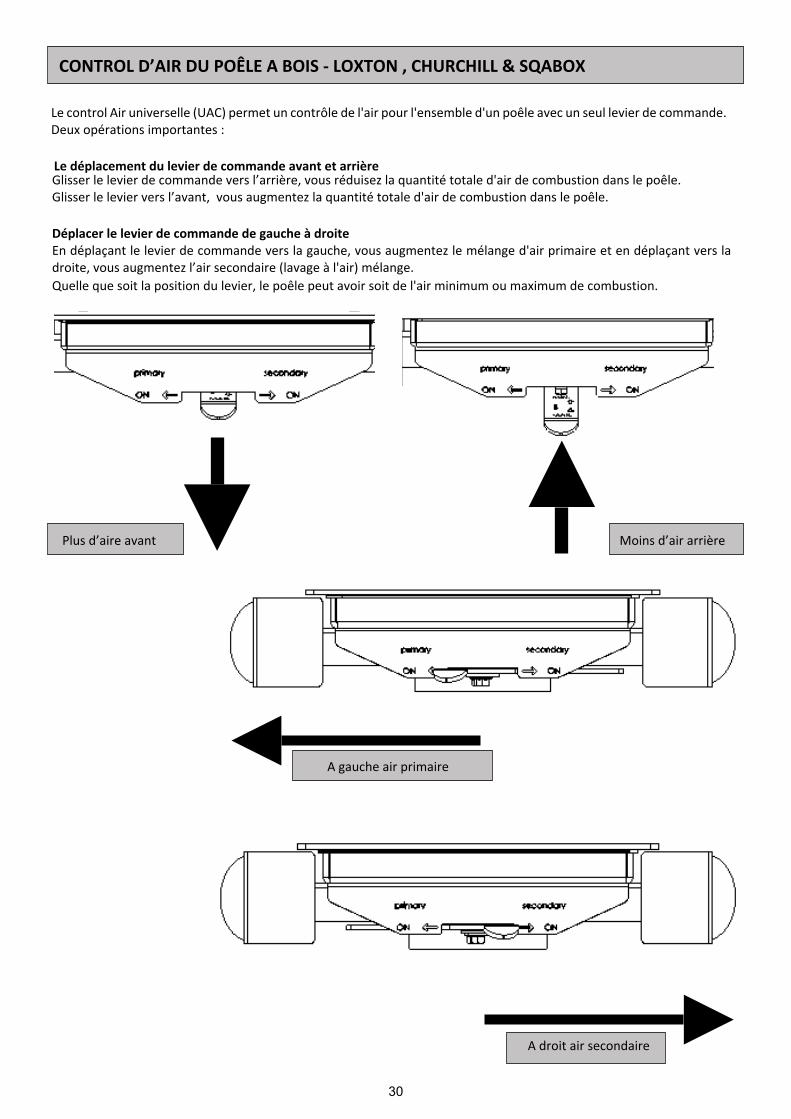
Le control Air universelle (UAC) permet un contrôle de l'air pour l'ensemble d'un poêle avec un seul levier de commande.Deux opérations importantes :
Le déplacement du levier de commande avant et arrièreGlisser le levier de commande vers l’arrière, vous réduisez la quantité totale d'air de combustion dans le poêle.Glisser le levier vers l’avant, vous augmentez la quantité totale d'air de combustion dans le poêle.
Déplacer le levier de commande de gauche à droiteEn déplaçant le levier de commande vers la gauche, vous augmentez le mélange d'air primaire et en déplaçant vers ladroite, vous augmentez l’air secondaire (lavage à l'air) mélange.Quelle que soit la position du levier, le poêle peut avoir soit de l'air minimum ou maximum de combustion.
A droit air secondaire
Plus d’aire avant Moins d’air arrière
A gauche air primaire
CONTROL D’AIR DU POÊLE A BOIS - LOXTON , CHURCHILL & SQABOX

31
Remarque : Si la conduit est à l’extérieure et en période de grand froid, il peut êtrenécessaire de réchauffer la cheminée en utilisant les allume-feux préalable àl'allumage avec du bois
1. Placez des petits bouts de bois sec (petit bois) dans le foyer par-dessus lesallume-feux non toxiques. Posez un ou deux bouts de bois sec fendu au quartpar-dessus. L’embrasement des bûches empilées sur le schéma permet la diffusionlibre de l’air de combustion ; ce qui facilite l’allumage.
2. Avancez entièrement vers l’avant la tirette d'air universelle (UAC) en dessous dela porte du poêle. Faites glisser pleinement à la position médiane. Le poêle disposedésormais d'un mélange d'air primaire air et secondaire pour le démarrage.
3. Allumez les allume-feux et poussez la porte en position fermée, le verrou en 1èreposition de sorte que la porte est ouverte de 2 mm (voir la photo). Cela fournit del'air de combustion en plus pour le démarrage et réduit la condensation sur la vitrede la porte. Il peut être nécessaire d’ouvrir un petit peu le cendrier (1-2 mm) pourbénéficier de plus d'air si la cheminée est lente.
4. Une fois les flammes du bois bien établies, ce qui peut prendre jusqu'à 10 minutes,la porte et ou le bac à cendre peut être fermé.
5. Laissez le contrôle d'air UAC dans la position centrale (si la tirette est au milieu ducontrôleur aérien, UAC fournit à la fois de l’air primaire et de l’air secondaire). Si lesflammes du poêle commencent à faiblir et générer de la fumée dans la chambre decombustion, déverrouillez la porte à nouveau jusqu'à ce que le feu soit rétabli.
BOIS DE CHAUFFAGEPour une utilisation optimale de votre poêle, il est nécessaire d’utiliser du bois de chauffage de bonne qualité. Il faut brulerun bois de chauffage sec issu de bois de feuillus (la teneur en humidité doit être inférieur ou égale à 20%). Le taux d’humiditédu bois joue un rôle important car l'utilisation de bois humide diminue le rendement de l’appareil et peut provoquer un filmde suie goudronneuse sur le fonctionnement interne de du poêle. Les bois récemment coupés contiennent 60-70% d'eau,ce qui rend totalement impropre à l'utilisation du bois de chauffage.
Tout bois récemment coupé, devrait être empilé et séché à l'air sous abri pendant deux ans avant d'être utilisé comme boisde chauffage.
6. Une fois le lit du feu établi, faites glisser lecontrôle UAC sur la position secondaire etappuyez sur le levier de 25%. Pour que le poêlebrûle proprement beaucoup d'air secondaire, il nefaut pas fermer le feu vers le bas, car cela peutprovoquer de la fumée. Une fois la puissancecalorifique nominale atteinte, faites le plein devotre poêle environ une fois par heure. Vérifiez lepoids des charges de votre modèle sur le tableaude la page 68.
Utilisez le gant lorsque vous utilisez lescommandes d'air et de la porte.
COMMENT ALLUMEZ VOTRE POÊLE À BOIS MENDIP
Le poêle devient très chaud lors de l'utilisation il faut être vigilent. Il est nécessaire d’utiliser le gantlorsque vous utilisez les commandes d'air, portes et cendrier.

32
Ne pas brûler des combustibles liquides, dérives du bois, bois fini, bois scié, des palettes en bois, agglomérécontreplaqué en bois ou en plastique recouvert de bois verni, bois traité avec des conservateurs, ou déchets domestique.Pour alimenter votre poêle de la manière la plus propre ne placez pas de combustible dans votre poêle lorsque lesflammes se sont apaisées ou que vous avez des braises.
Avant de faire le plein, ouvrez l'air pleinement et placer le levier à la position centrale. Déverrouillez la porte pour égaliserla pression de la chambre. Ouvrez la porte doucement, ajouter un morceau de bois (pour les 4,6 et 6 kW) ajouter deuxmorceaux de bois (pour les modèles 8 & 10kW), vérifier le poids (tableau page 28) et fermer la porte. Une fois lesflammes pleinement établies, placez la tirette UAC à la bonne position et poussez la tirette de control d'air 75% fermé.
L’utilisation du poêle déterminera les paramètres qui vont générer les meilleurs résultats. Utilisez un thermostat defumée pour vérifier que le poêle ne surchauffe pas. Les thermostats de fumée doivent être placés directement au-dessusdu poêle sur une section non isolée du tuyau (la zone efficace de température de fonctionnement est comprise entre 200cet 400c).
Si les contrôles d'air sur votre poêle sont fermés, une combustion incomplète peut conduire à une accumulation de suie,une suie dure et brillante à l'intérieur de votre poêle et sur la vitre.Pour éviter la prise de suie dans votre poêle et l’encrassement de la vitre :
1) Utilisez plus d'air secondaire2) Vérifiez que votre bois est adapté et sec.3) Vérifier que vous avez un tirage suffisant dans votre cheminée. Il est important de vérifier les conditions de tirage avantd'allumer votre poêle. Ceci peut être réalisé, par exemple, en plaçant d’un morceau de papier journal froissé et allumé. Lesconditions de tirage sont bonnes si la fumée est attirée par la cheminée.
Mendip Stoves sont conçus pour brûler du bois et du Charbon sans fumée de qualité
Comme un régime de temps de nuit, nous recommandons que la chamber de combusion est chargé quand il est chaud etbrûlé pendant cinq minutes avec le contrôle d'air secondaire complètement ouvert jusqu'à ce que le nouveau bois a priset est en train de brûler, puis fermer le tirette UAC d'air secondaire à sa position opérationnelle.
De retour au poêle dans la matinée, le feu aura éteinte, recharger avec du papier ou allume-feu et du petit bois et ouvrirle control d'air entièrement pour rallumer rapidement. Méfiez-vous que le lit de cendres aura braises chaudes.
CHARGEMENT DE BOIS
ENCRASSEMENT ET COMBUSTION INCOMPLÈTE
FONCTIONNEMENT PENDANT LA NUIT

33
Correctement installé, exploité et entretenu, votre poêle n’émettra pas de fumées dans l'habitation. Des Fuméesoccasionnelles lors du décendrage et du ravitaillement en bois peuvent se produire. Cependant, les émissions de fuméespersistantes sont potentiellement dangereuses et ne peuvent pas être tolérées.Si les émissions de fumée persistent, suivez ces instructions: a) Ouvrez les portes et les fenêtres pour ventiler la pièce, puis quittez les lieux. b) Sortir les bûches. c) Vérifier qu’il n’y ait pas d’obstruction dans la cheminée et procéder au nettoyage. d) Ne pas rallumer le feu jusqu'à la cause des fumées soit identifiée et traitée. Si nécessaire consulter un expert. La causela plus fréquente des émissions des fumées de combustion est liée à une obstruction dans la cheminée. Pour votrepropre sécurité, les conduits doivent être maintenus propres en permanence.
Alarme COVotre installateur doit être muni d'un avertisseur de CO dans la même pièce que l'appareil. Si l'alarme s’active de façoninattendue, suivez les instructions données sous "Attention Remarque" ci-dessus.
AérosolsLes aérosols sont inflammables et donc dangereux, ne pas les utiliser prés d’un poêle en fonctionnement.
1. Le feu ne prend pas - vérifiez
a) que l'entrée d'air ne soit pas obstruée d'aucune manièreb) que le conduit des fumées et de la cheminée soient dégagés c) l’utilisation d’un combustible adapté.d) l'alimentation suffisante en air de la pièce
e) que la pièce où est placé le poêle ne soit pas équipée d'un dispositif d'extraction (comme une VMC).
2. Flammes incontrôlables – vérifiez
a) que la porte soit bien ferméeb) que le contrôle d'air soit réglé au minimumc) que le registre d'entrée d'air soit fermé et qu’il ne
soit pas obstrué par la cendre ou un bout de tisond) qu'un combustible adapté soit utilisée) que les joints de la porte soient en bon étatf) que le tirage de la cheminée ne soit pas trop fort.g) que le joint du bac à cendres soit en bon état,h) qu’aucune cendre ne bloque le bac à cendres, si
nécessaire et nettoyer.
3. De la suie se forme sur la vitre – vérifiez
a) que le bois ne soit pas trop humide b) que l'arrivée d'air secondaire soit suffisantec) que le feu soit assez chaud.
4. Le poêle ne chauffe pas bien – vérifiez
a) que le bois ne soit pas trop humideb) que l'arrivée d'air secondaire soit suffisante.
5. Fumée ou odeur – vérifieza) que le tirage de la cheminée ne soit pas trop
faibleb) que la cheminée ou le tubage ne soient pas partiellement ou totalement bloquésc) que la hauteur de la cheminée soit adéquate par rapport à l'environnement
6. Suie dans la cheminée – vérifiez
a) que le bois ne soit pas trop humideb) que l'arrivée d'air secondaire soit suffisante.
ATTENTION
DIAGNOSTIC DES PROBLÈMES

34
Mendip Stoves recommande de nettoyer régulièrement votre poêle, retirez la cendre (hebdomadaire si l’utilisation estquotidiennement). Utiliser un cendrier rempli par trop de cendre peut entraver le fonctionnement du poêle et peut causerdes dommages sur la grille du poêle et sur le cendrier. Pour enlever le bac à cendre, utiliser l'outil et l’accrocher sur le devantdu cendrier. Soulevez et sortez de sa position en dessous de la chambre de combustion. Prenez soin de soutenir le cendrierpendant le mouvement, toujours porter un gant résistant à la chaleur. Assurez-vous que le poêle soit complètement froidavant de retirer les cendres (les braises peuvent rester chaudes pendant plus de 24 heures). Les cendres doivent être stockéesdans un récipient incombustible et ne doivent pas être mélangées avec d'autres déchets combustibles.
L'intérieur du poêle doit être nettoyé une fois par an. Pour nettoyer l'intérieur, enlevez toutes les cendres, la suie et lesrésidus de goudron de la chambre de combustion. Retirer les panneaux de chambre isolée et le déflecteur, la saleté et lasuie s’infiltrent derrière ces éléments et cela doit être nettoyé. Vérifiez la qualité de tous les panneaux isolés et remplacezles éléments endommagés ou fissurés, remplacez le joint de la porte du poêle. Vérifiez que le verre de la vitre soitcorrectement positionné. La connexion du conduit de fumée et la cheminée devraient être régulièrement vérifiées par unprofessionnel qualifié. Si pendant une période prolongée, le poêle n’est pas utilisé, il faut vérifier la cheminée, et écartertoute obstruction. La peinture, la laque peut devenir mince avec la chaleur dans des endroits exposés suite à une surchauffe.Les dommages de la peinture et de la laque, peuvent être réparés à l'aide de la Senotherm peinture ; une laque depulvérisation disponible chez votre revendeur Mendip. Pour nettoyer l'extérieur de la poêle, utiliser un chiffon sec.
Non utilisation prolongée (d'été)Si le poêle n’est pas utilisé pendant une période de temps prolongée (par exemple pendant l'été), alors, un nettoyage enprofondeur pour éliminer les résidus de cendres et de carburant non brûlé devrait être effectué. Pour permettre une bonnecirculation de l'air à travers l'appareil, pour réduire la condensation et les dommages ultérieur, laissez les contrôles d'aircomplètement ouvert. Il est important que la liaison du conduit de fumée, des déflecteurs ou des plaques de l'appareil dela gorge et la cheminée soit nettoyée avant l'allumage après une période d'arrêt prolongée.
Pièces de rechange et des modifications non autoriséesSeul les composants propres du fabricant, ou pièces de rechange recommandées et approuvées par des poêles Mendipdoivent être utilisés pour l'entretien de l'appareil et la réparation. Toute modification non autorisée annulera la garantie dupoêle et la conformité à la norme EN 13240.
Balayer vos cheminées et feux de cheminéeAssurez-vous que votre appareil, conduits de fumée et la cheminée sont balayés régulièrement. Cela peut être entamé lefonctionnement de votre appareil.Le ramonage régulier est essentiel et cela implique d’en effectuer un au moins une fois par an pour les carburants sans fuméeet un minimum de deux fois par an pour le bois. Si une plaque d'étranglement est incorporée, il est essentiel que la plaqueà aiguille soit retirée et nettoyée ci-dessus, toutes les cendres et les débris doivent être enlevés. Assurer un accès adéquataux portes de nettoyage là où il n’est pas possible de ramoner la cheminée à travers l'appareil. Si une cheminée a été utiliséepour une installation de feu ouvert, il est possible que la température des gaz de combustion plus élevée à partir d'un appareilfermé puisse desserrer les dépôts qui ont été précédemment formés, avec le risque de blocage des fumées. Il est doncrecommandé que la cheminée soit nettoyée une deuxième fois en un mois d'utilisation régulière après l'installation du poêle.
Incendies de cheminéeIl ne devrait pas y avoir d'incendies de cheminée si elle est bien ramonée régulièrement. Toutefois, si cet incident se produit,tournez le réglage du contrôle d'air au minimum et fermez soigneusement la porte du poêle. Ces mesures devraient éteindrel'incendie, auquel cas le contrôle doit rester au minimum jusqu'à ce que les flammes soient éteintes dans le poêle. Il fautensuite nettoyer la cheminée et le conduit de fumée. Si l'incendie ne s'éteint pas une fois les mesures ci-dessus prises,appeler immédiatement les sapeurs-pompiers. La cheminée doit être examinée en détail pour vérifier qu'elle ne soit pasendommagée. Consulter un spécialiste si nécessaire.
MAINTENANCE
L’ENTRETIEN ANNUEL

35
EN TEST - THE WOODLAND
Table 6 Temperature Safety test - The woodland - Report 59530/1 Edition 2

Mendip Stoves Ltd, 2016, ver 1 (mk3) July 2016 CODE:
Mendip Stoves Ltd
Unit H1,
Mendip Industrial Estate,
Mendip Road, Rooksbridge, Somerset
BS26 2UG
Tel: 01934 750 500
Fax: 01173 156 207
www. Mendipstoves.co.uk
E-mail : [email protected]
Distribué en France par la société / Distributed in France and Benelux by:-
Eurostove SASCentre d’AffairesRue de L’horlogerie BP 6001162401 Bethune [email protected] www.eurostove.fr
Part of Eurostove group