Embed Size (px)
Citation preview

Multi-Element VLC Networks: LED Assignment,
Power Control, and Optimum Combining
Yusuf Said Eroglu, Ismail Guvenc, Senior Member, IEEE, Alphan Sahin,
Yavuz Yapıcı, Nezih Pala and Murat Yuksel, Senior Member, IEEE
Abstract
Visible light communications (VLC) is a promising technology to address the spectrum crunch
problem in radio frequency (RF) networks. A major advantage of VLC networks is that they can use
the existing lighting infrastructure in indoor environments, which may have large number of LEDs for
illumination. While LEDs used for lighting typically have limited bandwidth, presence of many LEDs can
be exploited for indoor VLC networks, to serve each user by multiple LEDs for improving link quality
and throughput. In this paper, LEDs are grouped and assigned to the users based on received signal
strength from each LED, for which different solutions are proposed to achieve maximum throughput,
proportional fairness and quality of service (QoS). Additionally, power optimization of LEDs for a given
assignment is investigated, and Jacobian and Hessian matrices of the corresponding optimization problem
are derived. Moreover, for multi-element receivers with LED grouping at the transmitter, an improved
optimal combining method is proposed. This method suppresses interference caused by simultaneous
data transfer of LEDs and improves the overall signal-to-interference-plus-noise-ratio (SINR) by 2 dB
to 5 dB. Lastly, an efficient calculation of channel response is presented to simulate multipath VLC
channel with low computational complexity.
Index Terms
Combining receivers, free space optics (FSO), optical wireless communications (OWC), piezo
actuator, space division multiple access (SDMA).
arX
iv:1
707.
0536
1v1
[cs
.IT
] 1
7 Ju
l 201
7

2
I. INTRODUCTION
Light emmiting diodes (LEDs) have become increasingly popular within the last decade
as light sources due to their decreasing cost, low energy use and compatibility with different
applications such as dimming. One of the most important applications enabled by the proliferation
of LEDs is visible light communications (VLC) which transmit data in the visible light spectrum.
Light intensity of LEDs can be modulated with a high frequency, which allows data transmission
that is not perceivable to human eye [1]. VLC takes advantage of the light that is used for illumi-
nation as a communication channel and does not require additional signal for data transmission,
which provides an opportunity for energy efficiency. Moreover, since the light is directional and
does not penetrate walls, it allows high spatial reuse and provides inherent physical security [2].
VLC is also considered to be a complementary technology to radio frequency (RF) technologies
such as LTE and Wi-Fi [3].
A main disadvantage of VLC is that the achievable data rates with commercial LEDs are not
high due to their lower bandwidth. Phosphorescent white LEDs are reported to provide up to
20 MHz bandwidth, which enables up to 1 Gb/s data rates for a single user [4]. In order to
support multiple users and mobile applications that require significantly higher data rates and
longer coverage range, advanced transceiver techniques are required. For this purpose, in this
paper, we study three different approaches that can improve throughput for multi-element VLC
networks.
Firstly, we study the assignment of multiple LEDs to users in a multi-LED transmitter VLC
network. The number of LEDs is assumed to be much larger than the number of users, and
multiple highly directional LEDs are assigned to each user. Using this scheme, simultaneous
transmission to multiple users and hence higher signal-to-interference-plus-noise-ratio (SINR)
Yusuf Said Eroglu, Ismail Guvenc and Yavuz Yapıcı are with the Department of Electrical and Computer Engineering at the
North Carolina State University, Raleigh, NC. {email: {yeroglu, iguvenc, yyapici}@ncsu.edu}
Alphan Sahin is with InterDigital Communications Inc., Huntington Quadrangle, Melville, NY. {email: al-
Nezih Pala is with the Department of Electrical and Computer Engineering at Florida International University, Miami, FL.
{email: [email protected]}
Murat Yuksel is with the Department of Electrical and Computer Engineering at University of Central Florida, Orlando, FL.
This work is supported in part by NSF CNS awards 1422354 and 1422062, ARO DURIP award W911NF-14-1-0531, and
NASA NV Space Consortium.
3
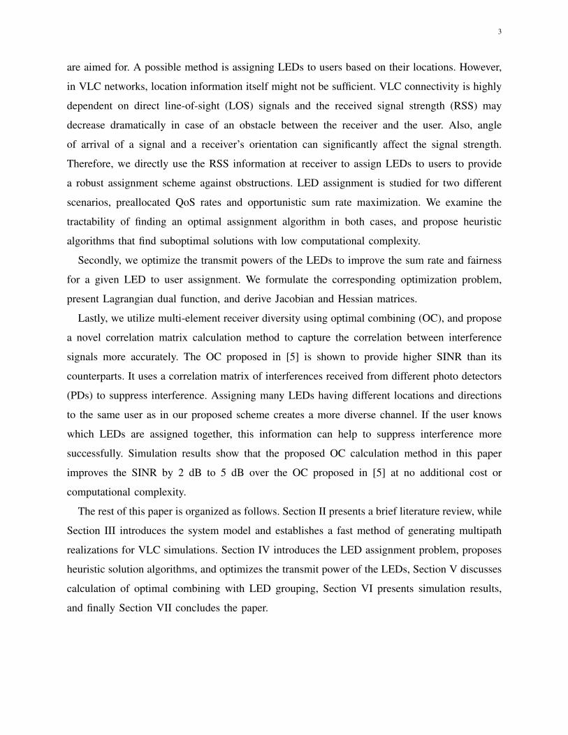
are aimed for. A possible method is assigning LEDs to users based on their locations. However,
in VLC networks, location information itself might not be sufficient. VLC connectivity is highly
dependent on direct line-of-sight (LOS) signals and the received signal strength (RSS) may
decrease dramatically in case of an obstacle between the receiver and the user. Also, angle
of arrival of a signal and a receiver’s orientation can significantly affect the signal strength.
Therefore, we directly use the RSS information at receiver to assign LEDs to users to provide
a robust assignment scheme against obstructions. LED assignment is studied for two different
scenarios, preallocated QoS rates and opportunistic sum rate maximization. We examine the
tractability of finding an optimal assignment algorithm in both cases, and propose heuristic
algorithms that find suboptimal solutions with low computational complexity.
Secondly, we optimize the transmit powers of the LEDs to improve the sum rate and fairness
for a given LED to user assignment. We formulate the corresponding optimization problem,
present Lagrangian dual function, and derive Jacobian and Hessian matrices.
Lastly, we utilize multi-element receiver diversity using optimal combining (OC), and propose
a novel correlation matrix calculation method to capture the correlation between interference
signals more accurately. The OC proposed in [5] is shown to provide higher SINR than its
counterparts. It uses a correlation matrix of interferences received from different photo detectors
(PDs) to suppress interference. Assigning many LEDs having different locations and directions
to the same user as in our proposed scheme creates a more diverse channel. If the user knows
which LEDs are assigned together, this information can help to suppress interference more
successfully. Simulation results show that the proposed OC calculation method in this paper
improves the SINR by 2 dB to 5 dB over the OC proposed in [5] at no additional cost or
computational complexity.
The rest of this paper is organized as follows. Section II presents a brief literature review, while
Section III introduces the system model and establishes a fast method of generating multipath
realizations for VLC simulations. Section IV introduces the LED assignment problem, proposes
heuristic solution algorithms, and optimizes the transmit power of the LEDs, Section V discusses
calculation of optimal combining with LED grouping, Section VI presents simulation results,
and finally Section VII concludes the paper.
4
II. LITERATURE REVIEW
In VLC networks, in order to provide ubiquitous illumination/wireless coverage, improve link
quality, and provide higher throughput, a large number of LEDs with directional propagation
characteristics can be deployed in indoor environments. Therefore, there might be significantly
larger number of LEDs than the number of users in the network, and it is possible to serve each
user with multiple directional LEDs over the same bandwidth [6]–[12]. In RF communications,
on the other hand, a single transmitter may serve many users at the same time simultaneously,
and users may connect to the transmitter with the highest received power [13], [14]. Coor-
dinated multipoint transmission (CoMP) technique offers serving a user with more than one
base station [15], [16], which is used in LTE-Advanced for interference management. However,
typically, the number of users connected to a base station is significantly higher than the number
of antennas deployed at the radio. The assignment techniques developed for RF communications
are hence not directly applicable to VLC networks. The problem of assigning LEDs to users
has similarities with the subchannel allocation in multiuser OFDM systems [17], [18]. However,
while assigning extra subchannel to a user affects its bandwidth, assigning an extra LED to a
VLC user affects its SINR, and hence the impact on the system performance will be different.
In [19], [20], joint transmission of information from multiple VLC nodes is studied, in order to
mitigate cell edge interference. An LED allocation scheme is presented in [21], which proposes
an LED array as VLC transmitter, assigning LEDs with respect to the number and location of
the users. However, it only provides a few fixed assignment options and cannot be generalized to
transmitter deployments with different geometries. The studies on resource allocation for VLC
networks [22], [23], reported in the literature focus on power allocation of LEDs and do not
address how to assign multiple LEDs to a single user.
In [11], a multi element transmitter structure is studied for VLC, where multiple LEDs directed
to different angles are placed on a light bulb. It is shown that multi-element transmitters serve
more users simultaneously and provides more spatial reuse compared to transmitters with less
directional LEDs. In [24], a spatial division multiple access (SDMA) scheme is described to serve
multiple users simultaneously by allocating them different LEDs, where the LED allocation is
decided based on the location of the user. However, as mentioned in the introduction, location
information itself might not always be sufficient to assign LEDs to users, since the RSS can
dramatically decrease in case of an obstruction or a change in the receiver orientation.
5
In addition to the use of multi-element LED assignments to users, using multiple PDs at
the receiver side is shown to improve the SINR performance [25]. The studies on imaging
angle diversity receiver for infrared communications have been a baseline for VLC related
extensions in this area [26]–[28]. In [28], the performance of angular diversity receivers with
multibeam infrared transmitters is investigated and it is concluded that diversity reduces the
ambient noise dramatically when used with maximum ratio combining (MRC). Alternatively, the
minimum-mean-squared-error interference-rejection-combining (MMSE-IRC) has been popular
in RF MIMO communications for improving SINR under interference, and included in LTE
standard with release 11 [29]. The MMSE-IRC is able to use the multiple receiver antennas to
create a null in the direction of the interference (where antenna gain significantly drops), and
therefore suppress the interference.
The OC is another related technique [5] that considers the correlation between interference
signals received from different PDs, and it suppresses the interference by using optimum com-
bining weights. In [25], it is shown that the OC provides the highest SINR for multi-PD VLC
and it is followed by the MRC, which weighs the PDs proportionally with their individual SINR
measurements. In [11], it is shown that the OC provides even higher gain in comparison to MRC
when multi-LED transmitters, as also considered in this paper, are used. However, these studies
do not consider grouping of LEDs to serve users. When LEDs are grouped, interfering LEDs
will also be grouped to serve other users, which will further increase the correlation between
interference signals. In this case, interference correlation matrix modeling of OC also needs to
change to.
III. SYSTEM MODEL
This section presents the network model, the VLC channel model, and the proposed method
for efficient calculation of channel response.
A. VLC Channel Model
We consider a multipath propagation environment in this paper based on the well-established
models in the literature for LOS and non-line-of-sight (NLOS) scenarios. In order to characterize
locations, orientations, and directionality of the LEDs, without loss of generality, the nth LED
Sn can be defined with three parameters as Sn = {r(n)tx ,q(n)tx , γ}, where r
(n)tx ∈ R3×1 is the
location of the nth LED, q(n)tx ∈ R3×1 is the orientation of nth LED, and γ is the parameter that
6
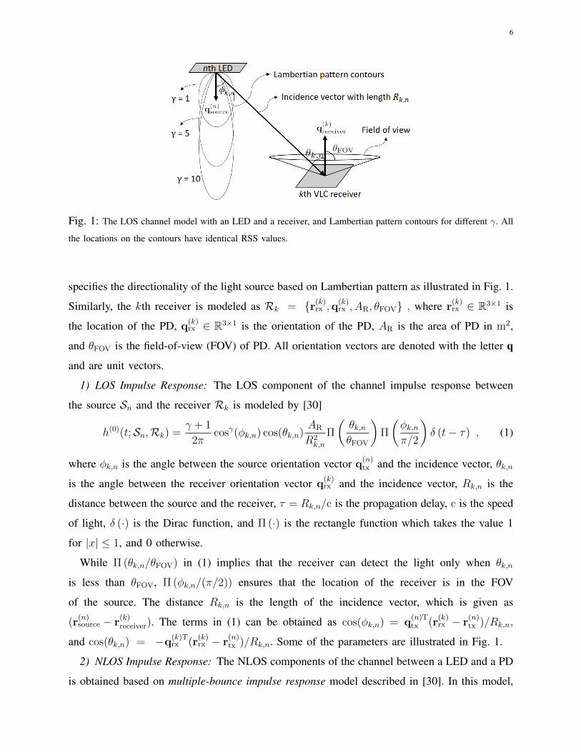
Fig. 1: The LOS channel model with an LED and a receiver, and Lambertian pattern contours for different γ. All
the locations on the contours have identical RSS values.
specifies the directionality of the light source based on Lambertian pattern as illustrated in Fig. 1.
Similarly, the kth receiver is modeled as Rk = {r(k)rx ,q(k)rx , AR, θFOV} , where r
(k)rx ∈ R3×1 is
the location of the PD, q(k)rx ∈ R3×1 is the orientation of the PD, AR is the area of PD in m2,
and θFOV is the field-of-view (FOV) of PD. All orientation vectors are denoted with the letter q
and are unit vectors.
1) LOS Impulse Response: The LOS component of the channel impulse response between
the source Sn and the receiver Rk is modeled by [30]
h(0)(t;Sn,Rk) =γ + 1
2πcosγ(φk,n) cos(θk,n)
AR
R2k,n
Π
(θk,nθFOV
)Π
(φk,nπ/2
)δ (t− τ) , (1)
where φk,n is the angle between the source orientation vector q(n)tx and the incidence vector, θk,n
is the angle between the receiver orientation vector q(k)rx and the incidence vector, Rk,n is the
distance between the source and the receiver, τ = Rk,n/c is the propagation delay, c is the speed
of light, δ (·) is the Dirac function, and Π (·) is the rectangle function which takes the value 1
for |x| ≤ 1, and 0 otherwise.
While Π (θk,n/θFOV) in (1) implies that the receiver can detect the light only when θk,n
is less than θFOV, Π (φk,n/(π/2)) ensures that the location of the receiver is in the FOV
of the source. The distance Rk,n is the length of the incidence vector, which is given as
(r(n)source − r
(k)receiver). The terms in (1) can be obtained as cos(φk,n) = q
(n)Ttx (r
(k)rx − r
(n)tx )/Rk,n,
and cos(θk,n) = −q(k)Trx (r
(k)rx − r
(n)tx )/Rk,n. Some of the parameters are illustrated in Fig. 1.
2) NLOS Impulse Response: The NLOS components of the channel between a LED and a PD
is obtained based on multiple-bounce impulse response model described in [30]. In this model,

7
user 1 user K
LED
12 3
N
. . . . . .
user k
n
Fig. 2: An example for LED assignment with K users and N LEDs clustered at two VLC access points. All
red dashed lines are assigned to user 1, all blue dotted lines are assigned to user k, while all solid green lines are
assigned to user K.
light from a source Sn can reach a receiver Rk after infinite number of diffuse reflections and
the channel impulse response is expressed as
h(t;Sn,Rk) =∞∑d=0
h(d)(t;Sn,Rk) , (2)
where t is the time index. Theoretically, h(d)(t;Sn,Rk) can be expressed as a recursive function
given by
h(d)(t;Sn,Rk) =
∫S
ρref × h(0)(t;Sn, {rref ,qref , dA,π
2}) ∗ h(d−1)(t; {rref ,qref , 1},Rk), (3)
where ∗ denotes the convolution operation. In (3), the vector rref ∈ R3×1 and the vector qref ∈
R3×1 correspond to the location and the orientation of the reflector, respectively, dA is the
infinitesimal area of the reflector, and ρref ∈ [0, 1) is the reflection coefficient. In addition, the
mode and the FOV of the reflector are set to 1 and π/2, respectively. The real-valued DC channel
gain [24], [25] between kth user and nth LED is then given by hkn =∫∞0h(t;Sn,Rk)dt.
B. VLC Network and SINR Model
We consider a VLC network as shown in Fig. 2 where K users are served by N LEDs such
that N � K. When more than a single LED is assigned to a user for a given case, the SINR

8
of the kth user can be improved, and expressed as:
SINR(k) =
( N∑n=1
rαknhknpn
)2
N0B +K∑`=1` 6=k
( N∑n=1
rα`nhknpn
)2, (4)
where r is the responsivity of the PD, pn is the standard deviation of the transmitted signal, N0 is
the spectral density of the additive white Gaussian noise (AWGN), and B is the communication
bandwidth. The connectivity variable is denoted by αkn, which is equal to 1 when nth LED is
assigned to kth user, and equal to 0 otherwise:
αkn ,
1 if nth LED serves kth user
0 if nth LED does not serve to kth user. (5)
To clarify our assumptions for the SINR in (4) and provide further insights, two remarks are
in order.
Remark 1. Several assumptions are made for the SINR in (4) to hold. First, it is assumed that
the transmission times of all LEDs are synchronized. Moreover, we assume that energy from the
signals arriving to user-k from the LEDs serving to that user can be coherently aggregated
as in the numerator of (4). This may for example be possible considering a guard period
among consecutive symbols [31] where the delays from different LEDs can be absorbed, and
inter-symbol-interference (ISI) effects [7], [32] are neglected. For modulation formats such as
orthogonal frequency division multiplexing (OFDM) based VLC, delays of the signals arriving
from different LEDs to a user can introduce phase changes at different subcarriers [33], which
is not explicitly considered here, and their impact on the SINR is left as a future work. Finally,
we also assume that the interference signals coming from a group of LEDs serving to the `th
user are assumed to add up linearly at the desired user (for example, again considering a guard
interval to absorb the energy).
Remark 2. As shown in the conceptual illustration of Fig. 3, we consider that the communication
signal sn(t) for the nth LED is carried on the background DC light intensity (with power Pave)
that is normally used for illumination. Zero mean communication signal sn(t) has a power
Pn = var(sn(t)), and therefore a standard deviation of pn =√Pn = std(sn(t)). The pn will be

9
𝑃ave
std𝑠 𝑛
𝑡=
𝑃 𝑛
Time0
Background (DC)
Lighting Level
sn(t): Communication Signal
Embedded over DC Lighting Level
Lig
ht A
mp
litu
de
Fig. 3: Conceptual illustration for the background DC level and communication signal on nth
LED for a transmitted VLC signal.
referred in the rest of the paper as the power coefficient for nth LED, and p = [p1, ..., pN ] will be
referred as the power coefficient vector. We assume that all LEDs provide the same background
light intensity (√Pave), which can be adjusted as desired, i.e., dimmed. On the other hand, we
consider that pn’s for different LEDs can be adjusted individually, considering 0≤ pn≤ pmax
where pmax is the maximum power attainable based on the LED saturation output and Pave.
The numerator term of (4) characterizes the received total signal power from multiple LEDs
serving user k. These LEDs transmit the same signal, and we sum all components to find the
aggregate signal strength. The second term of the denominator represents the interference from
LEDs serving simultaneously to K − 1 other users. Likewise, the LEDs serving user ` (` 6= k)
transmit the same signal, therefore their sum is considered as one interference component. Finally,
using αkns, we can construct a connectivity matrix A as follows:
A =
α11 α12 . . . α1N
α21 α22 . . . α2N
...... . . . ...
αK1 αK2 . . . αKN
, (6)
which can also capture the assignment of multiple LEDs to each user. Note that only a single
element in a column of A can be one, and all other elements are zeros, since an LED is assumed
to serve at most one user at a time. While techniques such as non-orthogonal multiple access
(NOMA) [34] and multi-user MIMO [33] are available where one LED may serve to more
than one user, they require higher complexity, and our main motivation in this paper is to take
advantage of large number of directional LEDs for a simple yet efficient design. On the other
hand, sum of each row in (6) is an integer greater or equal to one, since multiple LEDs can
10
serve a single user.
One of our goals in this paper is to find the matrix A under different optimization criteria to
maximize the capacity of users considering different constraints, where the capacity of the kth
user is given by
Rk = Blog2
(1 + SINR(k)
). (7)
We only study the downlink VLC capacity in this paper, and assume that users may have uplink
connectivity through an RF technology such as Wi-Fi. Moreover, we also assume that all LEDs
can transmit data in synchronization. These requirements can be accomplished by using a central
controller that controls all LEDs as well uplink RF reception from users. LEDs can be driven via
Power over Ethernet (PoE) directly by the central controller. Even though connecting all LEDs
to central controller (implying a star topology) may increase the installation cost due to longer
cable size, plug and play simplicity of PoE can decrease the labor costs [35]. Apart from making
synchronization of LEDs and control of downlink/uplink connections easier, another advantage
for the considered backhaul system is to remove the requirement for separate processors for each
VLC access point.
C. Efficient Calculation of the Channel Response
In practice, the integration in (3) can be evaluated by using the method of Riemann summation.
The summation can be further simplified by exploiting the recursive structure of (3). However,
when the operations are applied in time domain, the proposed method in [30] may still be
time consuming since the number of paths grows exponentially with the number of reflections,
and limits the number of reflections taken into account for calculating (2). In order to avoid
this limitation, we calculate (3) based on channel frequency response and corresponding matrix
formulation, which allows its efficient calculation for any given reflection order.
Assume that L reflectors are taken into account in order to model the multipath channel in
the environment. Such a spatial discretization leads to (3). Then, we let C(f) ∈ R(L+1)×(L+1)
be a matrix where the entry at ith row and jth column is
{C(f)}ij = h(0)(t;S(j)n ,R(i)
k )ej2πτijf , (8)
where i is the receiver index, j is the source index, R(i)k is the ith receiver, S(j)
n is the jth source,
τij is the propagation delay, and f is the frequency index. Without loss of generality, R(1)k and
S(1)n are the parameter sets for the LED and the PD, respectively, and the reflectors are indexed
11
by i, j ∈ {2, 3, . . . , L + 1}. Then, the received signal components at the receiver and at the
reflectors due to the light experiencing exactly d > 1 bounces is obtained as
pd(f) =[C(f)D
]dp0(f) , (9)
where pd(f) is the received signal power due to the dth order reflections, D is a diagonal matrix
where the diagonal elements include the reflection coefficients with entry {D}11 is set to 0, and
the vector p0(f) consists of the received signal power at the nodes due to the LOS component
of the channel. The vector p0(f) can be calculated as p0(f) = C(f)e , where e ∈ R(L+1)×1 is
the excitation vector with the first entry being 1 and the rest of the entries being zeros.
By using the eigenvalue decomposition of C(f)D, (9) can be rewritten as
pd(f) = Q[Λ(f)
]dQ−1p0(f) , (10)
where Q ∈ R(L+1)×(L+1) is a matrix whose columns are the eigenvectors of C(f)D and Λ is the
diagonal matrix whose diagonal elements are the corresponding eigenvalues. Therefore, (9) can
be calculated efficiently for an arbitrary number of multipath reflections, since Λ is a diagonal
matrix. By evaluating (10) for different frequencies, channel frequency response (CFR) can be
calculated for a given bandwidth and one can calculate the channel impulse response (CIR) from
CFR by using inverse Fourier transformation.
Note that the authors in [36] also suggest an efficient CIR calculation method for MIMO
systems by decomposing the channel response to three different matrices which represent the
receiver parameters, transmitter parameters, and indoor environment. However, (10) is differ-
ent than the model given in [36] as it takes the exact propagation delays into account, and
simultaneously calculates the impact of all of the paths on the CFR for a given frequency. The
equation (10) is used in all simulations in Section VI to generate multipath realizations.
IV. LED ASSIGNMENT TO USERS
In this section, we consider the problem of LED assignment to users for a network as in
Fig. 2 considering two different scenarios. In the first scenario studied in Section IV-A, there are
no QoS guarantees and the network provides the highest sum rate or the highest proportionally
fair sum rate. LED power control for this first scenario is also investigated in Section IV-B.
In the second scenario in Section IV-C, there are QoS guarantees and all users get data rates
proportional to their QoS ratios.

12
A. LED Assignment without QoS Guarantees
When there are no QoS guarantees, the problem of maximizing throughput can be expressed
as [A′,p′
]= arg max
A,p
K∑k=1
Rk,
subject to 0 ≤ pn ≤ pmax ∀n,
αkn ∈ {0, 1},K∑k=1
αkn ≤ 1 ∀n,
(11)
where A′ and p′ are the connectivity matrix and the power coefficient vector which maximize
the sum capacity over all possible values of A and p, respectively.
While the solution of (11) maximizes the total throughput, it does not consider the fairness
among the users, and it will assign most of the LEDs to the users with good SINRs. It has been
shown that maximizing the total logarithmic throughput achieves proportional fairness [37], [38].
If we aim at providing proportional fairness among users, the problem can be modified as follows:
[A′,p′
]= arg max
A,p
K∑k=1
log(Rk), (12)
subject to the same constraints as (11). Solution of this problem maximizes the throughput while
distributing LEDs in a proportionally fair manner with respect to users’ channel conditions. This
solution is also a special case of QoS-oriented LED assignment to be studied in Section IV-C.
The optimization problems in (11) and (12) are generally hard to solve since they include both
discrete and continuous variables. Such problems are called binary mixed-integer programming
problems in the literature [39]. To simplify the problem, we follow a suboptimal approach and
solve the problem in two steps. We first assume identical power level to all LEDs, which is the
maximum power coefficient pmax, and solve the LED assignment problem alone. In the second
step, we optimize the powers coefficients of LEDs, which is addressed in the next subsection of
this paper.
In [13], the problem of assigning users to base stations for 3G networks considering propor-
tional fairness is shown to be an NP-hard problem, which means there is no algorithm that can
find the optimum solution in polynomial time [40]. The problem in [13] is not the same as (12);
however if we switch the role of users and LEDs, we can establish a connection between the two
13
problems. In 3G networks, there are large number of users and fewer number of base stations,
and one user is connected to one base station at a given time. In our model, we assume that
there are larger number of LEDs than users, and an LED will be assigned to a single user at a
time. It can be shown that the problem in [13] can be reduced to (12), hence, assigning LEDs
to users is also an NP-hard problem.
NP-hard problems can be solved via exhaustive search; however, when the number of elements
(LEDs, users) increase, running time for exhaustive search becomes very large. In Section IV-E,
we present computational complexity of the exhaustive search along with the proposed assign-
ment algorithms, and show that the exhaustive search is computationally infeasible. Even though
one may find more efficient solutions than the exhaustive search, it is not possible to find a
solution with a running time proportional to a polynomial function of the problem size. Thus,
we focus on developing two different heuristic techniques that find close-to-optimal solutions
at low computational complexity. We also compare the performance of these heuristics with
exhaustive search for small number of users/LEDs in Section VII.
1) Highest RSS based assignment (HRS): In this algorithm, we assign an LED to the user that
receives the highest RSS from that LED. Considering that all LEDs provide the same transmit
power and all users have the same PD responsivity, the RSS is proportional to the channel gain.
Therefore, the user who will be served by the nth LED is given by
k = arg maxk
hkn, (13)
and hence, we have αkn = 1 for the particular LED. For all the other k 6= k, we have αkn = 0.
All LEDs are assigned in the same way without explicitly considering the fairness among users.
This is the simplest algorithm and gives high sum throughput, and we will refer to this algorithm
as the HRS algorithm.
2) Weighted signal strength based assignment (WSS): In this algorithm, we scale RSS with
the inverse of the total received signal power by that user. In particular, the weighted RSS for
nth LED by kth user is given by
Ψkn =rpnhkn
N∑m=1
(rpmhkm)2
∝ hknN∑m=1
h2km
. (14)
The proportionality in (14) holds because power coefficients of the LEDs are assumed to be
identical at this stage of the problem. Afterwards, each LED is assigned to the user with highest

14
weighted signal strength. In other words, for the nth LED, the user who will be served by that
LED is given by
k = arg maxk
Ψkn, (15)
and hence, we have αkn = 1. For all the other k 6= k and LED n, we have αkn = 0. This method
is expected to provide a more fair allocation than just assigning each LED to the user which
receives highest RSS from that LED. That is because it takes into account the aggregate signal
power a user receives and gives priority to users with low overall RSS.
B. LED Power Control
In this subsection, assuming that LEDs are assigned using an approach as discussed earlier,
we consider the problem of power control over the assigned LEDs to all users. In order to solve
the optimization problem in either (11) or (12) to find the optimal power coefficients pn, we
formulate the respective Lagrange dual function as follows
L(p,λ)=K∑k=1
Rk +N∑n=1
λn(pn− pmax)−N∑n=1
λn+Npn , (16)
where Rk is the generic rate function given as
Rk =
Rk , for the optimization in (11)
log(Rk) , for the optimization in (12), (17)
and all the Lagrange multipliers (λn’s) are stacked in the vector λ. The optimal power coefficient
can be solved either by i) finding roots of the derivative of the Lagrange function in (16)
with respect to unknowns p and λ via Newton based methods, or ii) directly minimizing the
optimization problem in (11) or (12) by interior-point or trust-region methods [41]. For either
approach, we need to derive the Jacobian and the Hessian matrices which will be provided in
Corollary 1. Before that, we first give the first and second-order derivatives of the rate functions
in Theorem 1, which will be necessary for the derivation in Corollary 1.
Theorem 1. Defining f(·) to be the mapping function for the LED assignment scheme such that
`= f(m) is the index for the user served by the mth LED, the first-order derivative of the rate
Rk with respect to the power coefficient is given as
∂Rk
∂pm=
B
ln2
2S`khkmTk
Cmk , (18)

15
where S`k=∑N
n=1 α`nhknpn, Tk =N0B/r+∑K
`=1 S2`k, and Cm
k =δ(k, l)−SINR(k)(1−δ(k, l))
with δ(·, ·) being the Kronecker delta function. Similarly, the second-order derivative of the rate
is given as
∂2Rk
∂pm∂pn=
B
ln2
4S`khkmS`′khknT 2k
Em,nk , (19)
where `′= f(n), and,
Em,nk =
−1 +
Tk2S2
`k
δ(`, `′) , k=`
SINR(k)
(2 +SINR(k)− Tk
2S2`k
δ(`, `′)
), k 6=`
.
While the derivatives of the generic rate function Rk in (17) is given directly by (18) and (19)
for the optimization problem in (11), respective derivatives for the optimization problem in (12)
are given as
∂Rk
∂pm=
1
Rk
∂Rk
∂pm,
∂2Rk
∂pm∂pn=
1
R2k
∂Rk
∂pm
∂Rk
∂pn+
1
Rk
∂2Rk
∂pm∂pn
Proof: See Appendix A.
Corollary 1. The Jacobian of the Lagrange dual function in (16) is given as
Jm =∂L(p,λ)
∂pm=
K∑k=1
∂Rk
∂pm+λm−λm+N ,
for 1 ≤ m ≤ N , and,
Jm =∂L(p,λ)
∂λm−N=
pm−N − pmax , N+1 ≤ m ≤ 2N
−pm−2N , 2N+1 ≤ m ≤ 3N.
Similarly, the Hessian of (16) is given as
Gm,n =∂Jm∂pn
=
K∑k=1
∂2Rk
∂pm∂pn, 1 ≤ m ≤ N
δ(m−N, n), N+1 ≤ m ≤ 2N
− δ(m−2N, n), 2N+1 ≤ m ≤ 3N
,
for 1 ≤ n ≤ N , and,
Gm,n =∂Jm∂λn−N
= δ(m,n−N)−δ(m+N, n−N),
for 1 ≤ m ≤ N,N+1 ≤ n ≤ 3N , and 0 otherwise.
Proof: The Jacobian and the Hessian are the first and the second-order derivatives of (16),
which can be readily computed using the derivatives in Theorem 1.
16
C. LED Assignment with QoS Guarantees
To make sure all users are allocated sufficient resources to satisfy their QoS, in this section
we also study the LED assignment problem with predetermined QoS ratios among the users.
Due to the complexity of the problem and space limitations, we leave the power control for
the LED assignment with QoS constraints as a future study. QoS guarantees enable users with
higher priorities to receive higher data rates by proportionally allocating the resources to the
users based on their QoS requirements. When QoS ratios are provided, the problem in (12) can
be modified as follows
A′ = arg maxA
K∑k=1
Rk,
subject to αkn ∈ {0, 1},K∑k=1
αkn ≤ 1 ∀n,
R1
ν1=R2
ν2= ... =
RK
νK,
(20)
where νk is the QoS ratio for user k. Assigning all users the same QoS ratios means maximizing
the sum rate while making all Rk’s equal and it corresponds to max-min problem, which is
maximizing the rate of the minimum rate user [18]. Therefore, max-min problem is a special
case of the problem in (20). The problem has similarities with the subchannel block allocation of
multiuser OFDM systems [17], assuming frequency selective quasistatic channels where channels
do not vary within a block of transmission. However, while assigning different number of LEDs
to the users alters the SINR of the users, assigning different number of subchannels to the the
users changes the assigned bandwidth to the users.
As a solution to problem (20), we present a new LED assignment heuristic given in Algo-
rithm 1. We define δk,n , (pnhkn)2/N0 as the signal-to-noise ratio (SNR) for user k and LED
n, Tk as the set of LEDs assigned to user k, and U as the set of unassigned LEDs. The algorithm
initially assigns one LED to each user, which is chosen based on the highest SNR to that user.
Then, iteratively, the algorithm lets the user with the least proportional capacity to pick up an
LED. The user picks up the LED that provides highest SNR from the available LEDs (U), and
the algorithm iterates until all LEDs are assigned.
17
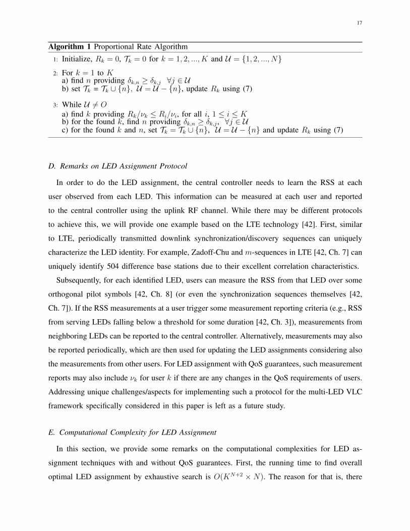
Algorithm 1 Proportional Rate Algorithm
1: Initialize, Rk = 0, Tk = 0 for k = 1, 2, ..., K and U = {1, 2, ..., N}
2: For k = 1 to Ka) find n providing δk,n ≥ δk,j ∀j ∈ Ub) set Tk = Tk ∪ {n}, U = U − {n}, update Rk using (7)
3: While U 6= Oa) find k providing Rk/νk ≤ Ri/νi, for all i, 1 ≤ i ≤ Kb) for the found k, find n providing δk,n ≥ δk,j , ∀j ∈ Uc) for the found k and n, set Tk = Tk ∪ {n}, U = U − {n} and update Rk using (7)
D. Remarks on LED Assignment Protocol
In order to do the LED assignment, the central controller needs to learn the RSS at each
user observed from each LED. This information can be measured at each user and reported
to the central controller using the uplink RF channel. While there may be different protocols
to achieve this, we will provide one example based on the LTE technology [42]. First, similar
to LTE, periodically transmitted downlink synchronization/discovery sequences can uniquely
characterize the LED identity. For example, Zadoff-Chu and m-sequences in LTE [42, Ch. 7] can
uniquely identify 504 difference base stations due to their excellent correlation characteristics.
Subsequently, for each identified LED, users can measure the RSS from that LED over some
orthogonal pilot symbols [42, Ch. 8] (or even the synchronization sequences themselves [42,
Ch. 7]). If the RSS measurements at a user trigger some measurement reporting criteria (e.g., RSS
from serving LEDs falling below a threshold for some duration [42, Ch. 3]), measurements from
neighboring LEDs can be reported to the central controller. Alternatively, measurements may also
be reported periodically, which are then used for updating the LED assignments considering also
the measurements from other users. For LED assignment with QoS guarantees, such measurement
reports may also include νk for user k if there are any changes in the QoS requirements of users.
Addressing unique challenges/aspects for implementing such a protocol for the multi-LED VLC
framework specifically considered in this paper is left as a future study.
E. Computational Complexity for LED Assignment
In this section, we provide some remarks on the computational complexities for LED as-
signment techniques with and without QoS guarantees. First, the running time to find overall
optimal LED assignment by exhaustive search is O(KN+2 × N). The reason for that is, there
18
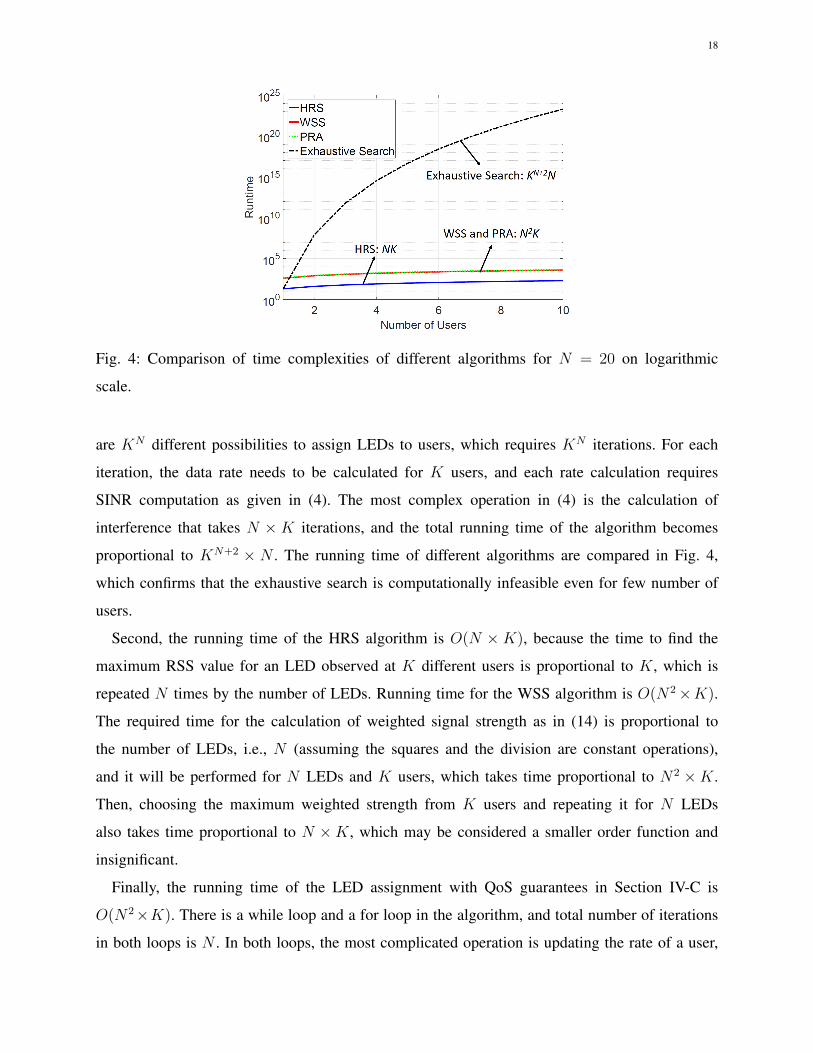
Fig. 4: Comparison of time complexities of different algorithms for N = 20 on logarithmic
scale.
are KN different possibilities to assign LEDs to users, which requires KN iterations. For each
iteration, the data rate needs to be calculated for K users, and each rate calculation requires
SINR computation as given in (4). The most complex operation in (4) is the calculation of
interference that takes N ×K iterations, and the total running time of the algorithm becomes
proportional to KN+2 × N . The running time of different algorithms are compared in Fig. 4,
which confirms that the exhaustive search is computationally infeasible even for few number of
users.
Second, the running time of the HRS algorithm is O(N ×K), because the time to find the
maximum RSS value for an LED observed at K different users is proportional to K, which is
repeated N times by the number of LEDs. Running time for the WSS algorithm is O(N2×K).
The required time for the calculation of weighted signal strength as in (14) is proportional to
the number of LEDs, i.e., N (assuming the squares and the division are constant operations),
and it will be performed for N LEDs and K users, which takes time proportional to N2 ×K.
Then, choosing the maximum weighted strength from K users and repeating it for N LEDs
also takes time proportional to N ×K, which may be considered a smaller order function and
insignificant.
Finally, the running time of the LED assignment with QoS guarantees in Section IV-C is
O(N2×K). There is a while loop and a for loop in the algorithm, and total number of iterations
in both loops is N . In both loops, the most complicated operation is updating the rate of a user,
19
which requires SINR calculation that takes time proportional to N ×K. It is executed once in
any of N iterations, so the total running time is proportional to N2 ×K (See Fig. 4).
V. DIVERSITY COMBINING
In Section IV we discussed the LED assignment problem, presented our solutions, demon-
strated their time complexities, and provided a power control approach for improved performance.
In this section, we propose an advanced receiver combining method that further improves the
SINR, by taking advantage of the LED assignment information to the users. When multiple PDs
are used at a receiver, the SINR of kth user after combining over multiple PDs can be calculated
as:
SINR(k) =
( N∑n=1
M∑m=1
rαknpnwmhk(m)n
)2
M∑m=1
w2mN0B +
K∑`=1`6=k
( N∑n=1
M∑m=1
rα`npnwmhk(m)n
)2, (21)
where wm is the weight for mth PD, M is the number of PDs on a receiver, hk(m)n is the channel
attenuation between nth LED and mth PD of kth user, and the second term in the denominator
represents the sum of all interference signal powers at all PDs from all LEDs excluding the LED
group which serves the kth user. Choosing of wm for combining signals at the receiver can be
achieved using the MRC or the OC approaches, as will be discussed next.
A. Maximum Ratio Combining
The MRC uses the signals received from different PDs with a proportional weight to the SINR
observed at each PD. Weight of mth PD is calculated as
wm =
( N∑n=1
rαknpnhk(m)n
)2
N0B +K∑`=1` 6=k
( N∑n=1
rα`npnhk(m)n
)2. (22)
The numerator of (22) is for the received signal power at mth PD, and the denominator is for
the sum of noise and interference. The MRC is a heuristic to use all data with a proportional
ratio to maximize the combined SINR, however, it assumes that the signals received at different
PDs are uncorrelated. While this approach is successful at suppressing the white noise, it yields
suboptimal performance for correlated noise or interference.
20
B. OC with Unknown Grouping Information
The OC provides higher SINR performance than the MRC by suppressing correlated interfer-
ence. In order to calculate the weights of the kth user, denote
Hk,k(m) = r
N∑n=1
αknpnhk(m)n, (23)
to be the sum of the received desired signals at kth user’s mth PD. We can build a vector
vkk = [Hk,k(1), Hk,k(2), ..., Hk,k(M)]T (24)
which includes the received desired signals through different PDs. The weighting vector for OC
can then be calculated as
w = R−1vkk, (25)
where R is the interference-plus-noise correlation matrix of the received signal, explicitly given
by
R = N0BI +N∑n=1
(1− αkn)E[hknhTkn], (26)
where
hkn = rpn[hk(1)n, hk(2)n, ..., hk(M)n]T , (27)
which is the signal vector that the kth user captures from the nth LED through different PDs.
In (26), while the first term of the summation is the noise correlation matrix, the second term
is the interference correlation matrix. The expression (1 − αkn) ensures that only interference
signals will be added, because αkn is the assignment flag and if nth LED is assigned to kth
user, (1− αkn) is equal to zero.
C. OC with Known Grouping Information
If we calculate the interference without considering assignment information, we will ignore the
correlation between LEDs that are transmitting to the same interfering user. When the grouping
information between interfering LEDs is known, rather than using (26), R for the kth user can
be calculated as
R = N0BI +K∑`=1` 6=k
E[v`kvT`k], (28)
21
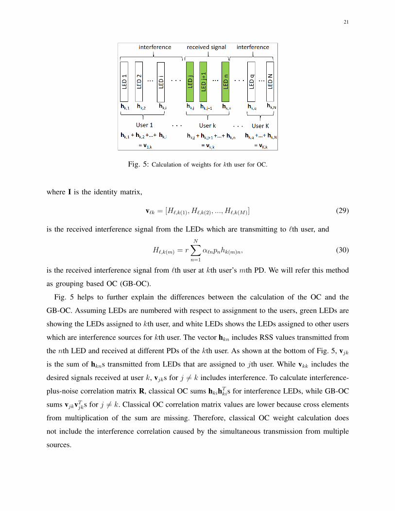
Fig. 5: Calculation of weights for kth user for OC.
where I is the identity matrix,
v`k = [H`,k(1), H`,k(2), ..., H`,k(M)] (29)
is the received interference signal from the LEDs which are transmitting to `th user, and
H`,k(m) = rN∑n=1
α`npnhk(m)n, (30)
is the received interference signal from `th user at kth user’s mth PD. We will refer this method
as grouping based OC (GB-OC).
Fig. 5 helps to further explain the differences between the calculation of the OC and the
GB-OC. Assuming LEDs are numbered with respect to assignment to the users, green LEDs are
showing the LEDs assigned to kth user, and white LEDs shows the LEDs assigned to other users
which are interference sources for kth user. The vector hkn includes RSS values transmitted from
the nth LED and received at different PDs of the kth user. As shown at the bottom of Fig. 5, vjkis the sum of hkns transmitted from LEDs that are assigned to jth user. While vkk includes the
desired signals received at user k, vjks for j 6= k includes interference. To calculate interference-
plus-noise correlation matrix R, classical OC sums hkihTkis for interference LEDs, while GB-OC
sums vjkvTjks for j 6= k. Classical OC correlation matrix values are lower because cross elements
from multiplication of the sum are missing. Therefore, classical OC weight calculation does
not include the interference correlation caused by the simultaneous transmission from multiple
sources.

22
Fig. 6: The 12m by 12m room and the transmitter locations for simulation evaluations.
D. Relaying Global LED Assignment to Users
In order for a receiver to implement GB-OC, the LED assignments to all individual users need
to be known by each user, which is characterized by the sparse matrix A in (6). Since all users
needs the same information, LED assignment information can be simultaneously broadcast from
all the LEDs. The broadcast should be done right after a new LED assignment is computed, and
before users start being served with the new assignment.
In the simplest approach, the assignment matrix A can be broadcast from the LEDs to users,
which corresponds to an overhead of N × K bits. Due to the sparse nature of the matrix A
(each LED serving only one user), each column of A can be replaced by a single bit vector
of size dlog2(K + 1)e representing the identity of the user that is served by a particular LED,
and a bit sequence of all zeros if the LED does not serve any user. This second approach
therefore requires an overhead on the order of N × log2K. LED assignment overhead can be
further reduced by grouping LEDs and assigning them to users in groups, which is reminiscent
to group-based resource block assignment using the bitmap type-0 and type-1 to reduce control
channel overhead in LTE networks [42, Table 9.4].
VI. SIMULATION RESULTS
For simulations, a square room with dimensions 12 m × 12 m × 4 m is considered as in
Fig. 6. Four multi-element transmitters are considered, each having seven LEDs. In a multi-
element transmitter, while one LED is directed downwards, there is a second layer of LEDs
having a 45◦ divergence angle with the center LED. The transmitters are located at the ceiling
facing downwards; the receivers are assumed to be at 0.85 m height and facing upwards. Other
23
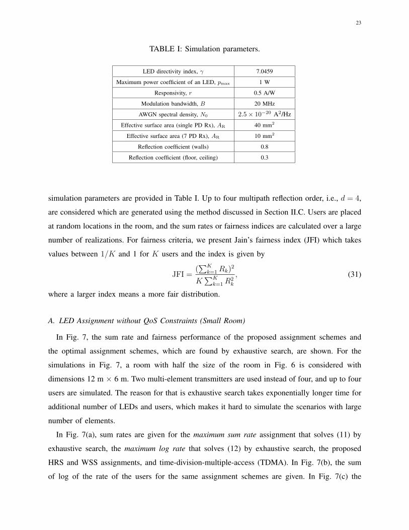
TABLE I: Simulation parameters.
LED directivity index, γ 7.0459
Maximum power coefficient of an LED, pmax 1 W
Responsivity, r 0.5 A/W
Modulation bandwidth, B 20 MHz
AWGN spectral density, N0 2.5× 10⁻²⁰ A2/Hz
Effective surface area (single PD Rx), AR 40 mm2
Effective surface area (7 PD Rx), AR 10 mm2
Reflection coefficient (walls) 0.8
Reflection coefficient (floor, ceiling) 0.3
simulation parameters are provided in Table I. Up to four multipath reflection order, i.e., d = 4,
are considered which are generated using the method discussed in Section II.C. Users are placed
at random locations in the room, and the sum rates or fairness indices are calculated over a large
number of realizations. For fairness criteria, we present Jain’s fairness index (JFI) which takes
values between 1/K and 1 for K users and the index is given by
JFI =(∑K
k=1Rk)2
K∑K
k=1R2k
, (31)
where a larger index means a more fair distribution.
A. LED Assignment without QoS Constraints (Small Room)
In Fig. 7, the sum rate and fairness performance of the proposed assignment schemes and
the optimal assignment schemes, which are found by exhaustive search, are shown. For the
simulations in Fig. 7, a room with half the size of the room in Fig. 6 is considered with
dimensions 12 m × 6 m. Two multi-element transmitters are used instead of four, and up to four
users are simulated. The reason for that is exhaustive search takes exponentially longer time for
additional number of LEDs and users, which makes it hard to simulate the scenarios with large
number of elements.
In Fig. 7(a), sum rates are given for the maximum sum rate assignment that solves (11) by
exhaustive search, the maximum log rate that solves (12) by exhaustive search, the proposed
HRS and WSS assignments, and time-division-multiple-access (TDMA). In Fig. 7(b), the sum
of log of the rate of the users for the same assignment schemes are given. In Fig. 7(c) the
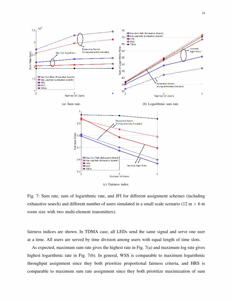
24
(a) Sum rate. (b) Logarithmic sum rate.
(c) Fairness index.
Fig. 7: Sum rate, sum of logarithmic rate, and JFI for different assignment schemes (including
exhaustive search) and different number of users simulated in a small scale scenario (12 m × 6 m
room size with two multi-element transmitters).
fairness indices are shown. In TDMA case, all LEDs send the same signal and serve one user
at a time. All users are served by time division among users with equal length of time slots.
As expected, maximum sum rate gives the highest rate in Fig. 7(a) and maximum log rate gives
highest logarithmic rate in Fig. 7(b). In general, WSS is comparable to maximum logarithmic
throughput assignment since they both prioritize proportional fairness criteria, and HRS is
comparable to maximum sum rate assignment since they both prioritize maximization of sum

25
rate. HRS and WSS algorithms provide lower sum rate in comparison to the corresponding
optimal assignment schemes; however, they both outperform TDMA in terms of data rate. Since
the proposed assignment scheme makes use of space diversity, in a larger room or with higher
number of users the rate gain over TDMA is expected to be higher (see Fig. 8). In terms of
logarithmic rate, which is a parameter for both higher rate and fair distribution, WSS gives close
results to the maximum log rate and TDMA, and it is followed by HRS with a larger margin.
Maximum sum rate assignment fails the logarithmic rate criteria and provides the lowest results.
In terms of the JFI criteria, WSS provides close results to the max log rate and HRS provides
close results to the max sum rate.
B. LED Assignment without QoS Constraints (Large Room)
In Fig. 8, the room setup in Fig. 6 is used, where exhaustive simulation results are excluded due
to extensively long (on the order of months) simulation duration with today’s high performance
computers, even with as low as four users. In Fig. 8(a), the sum rate for HRS and WSS based
algorithms are shown. The results with TDMA are also shown for reference. While HRS shows
the highest sum rate performance, WSS has slightly lower rate. As HRS assigns each LED
to the user with the highest received signal, and does not consider any fairness criterion, it
is expected to yield the highest sum throughput. Sum rates with optimized power coefficients
are also shown with dotted lines. All power optimization simulations in this paper maximize
the sum of logarithmic throughput as in (12), using interior-point method. The results show
that optimization provides significant gain in the sum rate of both algorithms. Both algorithms
constantly improve the sum rate when the number of users increase, by making use of spatial
diversity. When there are 8 users, the proposed algorithms provide more than three times gain
over TDMA in terms of data rate. When there are 14 users, the gain reaches approximately five
times that of TDMA.
In Fig. 8(b) the sum of logarithmic rate performances are shown. WSS shows a similar
performance as TDMA by means of logarithmic sum, while HRS yields lower results, especially
for higher number of users. Power optimization slightly increases logarithmic sum rate of both
algorithms. In Fig. 8(c), the fairness index for the same algorithms is given. The WSS provides
significantly higher fairness index in comparison to the HRS, since it considers the whole
received signal power by a user and provides a more fair LED assignment. Power optimization
increases the fairness index of the HRS significantly, since it maximizes the logarithmic sum

26
2 4 6 8 10 12 14Number of Users
1
2
3
4
5
6
7
8
9S
um R
ate
(bps
)108
HRS (w/o Power Optimization)HRS (with Power Optimization)WSS (w/o Power Optimization)WSS (with Power Optimization)TDMA
(a) Sum rates for different number of users.
2 4 6 8 10 12 14Number of Users
40
60
80
100
120
140
160
180
200
220
Sum
of l
ogar
ithm
ic r
ate
HRS (w/o Power Optimization)HRS (with Power Optimization)WSS (w/o Power Optimization)WSS (with Power Optimization)TDMA
(b) Sum of logarithmic rates for different number of users.
2 4 6 8 10 12 14Number of Users
0.5
0.6
0.7
0.8
0.9
1
Fai
rnes
s In
dex
HRS (w/o Power Optimization)HRS (with Power Optimization)WSS (w/o Power Optimization)WSS (with Power Optimization)TDMA
(c) Fairness indexes for different number of users.
Fig. 8: Sum rate, sum of logarithmic rate, and JFI for different assignment schemes and different
number of users (12 m × 12 m room size with four multi-element transmitters as in Fig 6).
rate. Contribution of power optimization to the fairness index of WSS is not that significant. It
even causes fairness index to decrease for low number of users. The reason is that, WSS already
provides a high fairness index before optimization, and improving logarithmic sum slightly may
not improve the fairness index of WSS in all cases. The advantage of power optimization on
WSS is mostly visible on the sum rate.

27
2 Users
0 1Power (W)0
5
10
15103 6 Users
0 1Power (W)0
5
10
15103
10 Users
0 1Power (W)0
5
10
15103 14 Users
0 1Power (W)0
5
10
15103
(a) Histogram of power coefficients after optimization. The x-
axes show the power values, and y-axes show total number of
users taking those values (pmax = 1 W).
5 10 20 2515LED index
0
0.2
0.4
0.6
0.8
1
Pow
er (
W)
(b) Power coefficients of LEDs for different pmax values in a
single optimization realization. Different users are shown with
different markers.
Fig. 9: Power coefficients after optimization.
C. Power Control and Illumination
Fig. 9(a) shows the histogram of the power coefficients of the simulations in Fig. 8 for WSS
(with Power Optimization) case. The histograms shows that the optimum power coefficient tends
to be either 1 or 0, depending on if the LED provides more signal power or more interference
(to other users), respectively. A similar power control problem is studied in [43] under multiple
interfering RF links, where they identify scenarios which binary power control is optimal. It
might as well be the case in VLC scenarios with high number of LEDs, which we leave as a
future study to investigate. In Fig. 9(a), when the number of users increases, lower number of
LEDs takes 0 power, which is probably due to decreasing LEDs per user. Since the optimization
maximizes sum of logarithmic throughput, it makes sure every user is served by LEDs that are
assigned a power coefficient larger than zero.
In case of dimming, Pave needs to be decreased and it may also limit pmax. In order to evaluate
effects of dimming on power optimization, Fig. 9(b) shows the power levels of all LEDs for a
single optimization realization, for different pmax values, that are 1 W, 0.6 W, and 0.2 W. The
WSS algorithm is used to assign LEDs to six users, and different users are shown with different
markers. While some users are assigned a single LED, some others are assigned as much as 10

28
2 4 6 8 10 12Number of Users
2
2.5
3
3.5
Sum
Rat
e (b
ps)
#108
PRA (81= ... = 8
K = 1)
PRA (8i=5 for i5K/2, 8
i=1 for i > K/2)
TDMA
Fig. 10: Sum rate for PRA and TDMA for different number of users.
LEDs, depending on the distribution of users in the room. For pmax = 1 W, many LEDs are
assigned a power coefficient of zero, which can also be seen from the histograms in Fig. 9(a).
When pmax is decreased to 0.2 W, no LED is assigned zero power, and most LEDs are assigned
the maximum power value of pmax. This shows that for lower values of pmax, noise becomes
the dominant factor rather than interference, which makes pmax optimal for most LEDs.
D. LED Assignment with QoS Constraints
In Fig. 10, the sum rate with the PRA algorithm for two different QoS ratios (defined in
(20)) are compared with TDMA. For the results with square marker, half of the users’ QoS
ratios are 5, and the remaining ones have a ratio of 1. With TDMA, users can be provided
proportional rates by assigning them proportionate time. However, after averaging over large
number of realizations, the sum rate is the same for any ratio allocation among users, since
users are randomly located at each realization. The PRA provides higher sum rate with respect
to TDMA for any number of users and any QoS ratio distribution. As the number of users
increases, the capacity gain also increases with respect to TDMA. As mentioned before, this is
due to increased spatial diversity between LEDs and users.
With PRA algorithm, QoS ratio difference between users affects sum throughput negatively
when the number of users is less than four. In this case, the distribution with equal ratios gives
29
higher sum rate. However, with higher number of users, different QoS ratios do not affect the
sum rate negatively. It even provides a slight gain over equal ratio distribution among users.
One of the reasons for this behavior is that, since the SINR is proportional to the square of the
received signal strength at the receiver, assigning more LEDs on some of the users may increase
the rate of those users more than the amount of decrease at the other users.
E. Diversity Combining
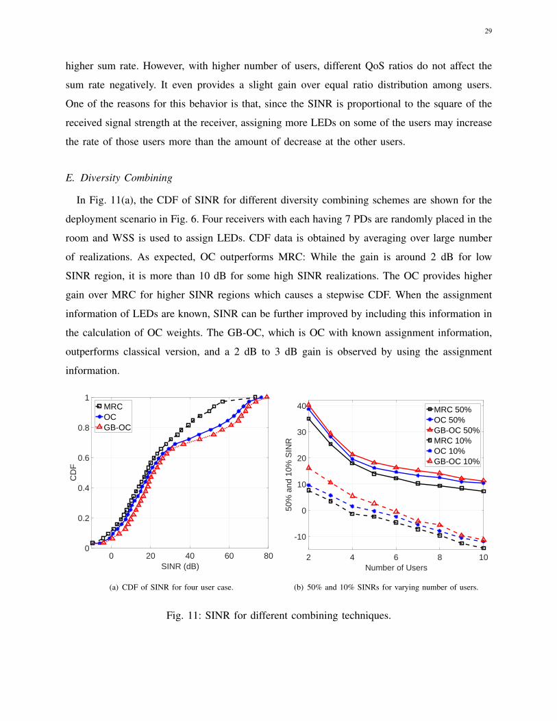
In Fig. 11(a), the CDF of SINR for different diversity combining schemes are shown for the
deployment scenario in Fig. 6. Four receivers with each having 7 PDs are randomly placed in the
room and WSS is used to assign LEDs. CDF data is obtained by averaging over large number
of realizations. As expected, OC outperforms MRC: While the gain is around 2 dB for low
SINR region, it is more than 10 dB for some high SINR realizations. The OC provides higher
gain over MRC for higher SINR regions which causes a stepwise CDF. When the assignment
information of LEDs are known, SINR can be further improved by including this information in
the calculation of OC weights. The GB-OC, which is OC with known assignment information,
outperforms classical version, and a 2 dB to 3 dB gain is observed by using the assignment
information.
0 20 40 60 80SINR (dB)
0
0.2
0.4
0.6
0.8
1
CD
F
MRCOCGB-OC
(a) CDF of SINR for four user case.
2 4 6 8 10Number of Users
-10
0
10
20
30
40
50%
and
10%
SIN
R
MRC 50%OC 50%GB-OC 50%MRC 10%OC 10%GB-OC 10%
(b) 50% and 10% SINRs for varying number of users.
Fig. 11: SINR for different combining techniques.
30
Fig. 11(b) shows the 50% and 10% of SINR CDF for different number of users, again while
utilizing the WSS-based LED assignment. 50% stands for median SINR and 10% is for the
lowest 10% of all SINR values. At least a few dB gain is provided by GB-OC for any number
of users in both cases. The gain decreases with increasing number of users, especially for 10%
SINR. The reason for that is when there are more users in the room, LED groups are smaller.
Therefore coordination caused by grouping of LEDs decreases. We can observe that when the
number of users becomes closer to the number of LEDs, GB-OC converges to classical OC.
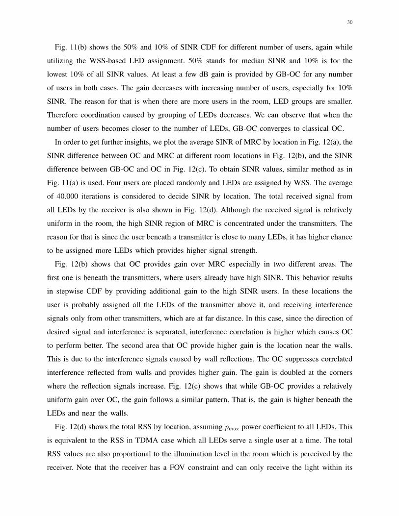
In order to get further insights, we plot the average SINR of MRC by location in Fig. 12(a), the
SINR difference between OC and MRC at different room locations in Fig. 12(b), and the SINR
difference between GB-OC and OC in Fig. 12(c). To obtain SINR values, similar method as in
Fig. 11(a) is used. Four users are placed randomly and LEDs are assigned by WSS. The average
of 40.000 iterations is considered to decide SINR by location. The total received signal from
all LEDs by the receiver is also shown in Fig. 12(d). Although the received signal is relatively
uniform in the room, the high SINR region of MRC is concentrated under the transmitters. The
reason for that is since the user beneath a transmitter is close to many LEDs, it has higher chance
to be assigned more LEDs which provides higher signal strength.
Fig. 12(b) shows that OC provides gain over MRC especially in two different areas. The
first one is beneath the transmitters, where users already have high SINR. This behavior results
in stepwise CDF by providing additional gain to the high SINR users. In these locations the
user is probably assigned all the LEDs of the transmitter above it, and receiving interference
signals only from other transmitters, which are at far distance. In this case, since the direction of
desired signal and interference is separated, interference correlation is higher which causes OC
to perform better. The second area that OC provide higher gain is the location near the walls.
This is due to the interference signals caused by wall reflections. The OC suppresses correlated
interference reflected from walls and provides higher gain. The gain is doubled at the corners
where the reflection signals increase. Fig. 12(c) shows that while GB-OC provides a relatively
uniform gain over OC, the gain follows a similar pattern. That is, the gain is higher beneath the
LEDs and near the walls.
Fig. 12(d) shows the total RSS by location, assuming pmax power coefficient to all LEDs. This
is equivalent to the RSS in TDMA case which all LEDs serve a single user at a time. The total
RSS values are also proportional to the illumination level in the room which is perceived by the
receiver. Note that the receiver has a FOV constraint and can only receive the light within its
31
0 2 4 6 8 10 12
x axis (m)
12
10
8
6
4
2
0
y ax
is (
m)
-10
0
10
20
30
40
50
60
dB
(a) SINR distribution in the room with MRC.
0 2 4 6 8 10 12
x axis (m)
12
10
8
6
4
2
0
y ax
is (
m)
0
5
10
15
20
25
dB
(b) SINR gain of OC over MRC.
0 2 4 6 8 10 12
x axis (m)
12
10
8
6
4
2
0
y ax
is (
m)
0
2
4
6
8
10
12
dB
(c) SINR gain of GB-OC over OC.
0 2 4 6 8 10 12
x axis (m)
12
10
8
6
4
2
0
y a
xis
(m
)
1
1.5
2
2.5
3
3.5
4
W
(d) Total RSS at the receiver (also equal to RSS for
TDMA case).
Fig. 12: RSS and SINR measurements for different locations within the room of Fig. 6. The
WSS is used to assign the LEDs to four randomly located users. Triangle markers show the
location of the multi-LED VLC access points.
FOV. Both the illumination and the RSS have a close to a uniform distribution within the room
for the given simulation setup.
VII. CONCLUSION
In this paper, we investigate LED-user assignment problem in a downlink VLC scenario,
where multiple LEDs serve multiple users. We study suboptimal but computationally efficient

32
LED assignment algorithms and power optimization techniques while taking proportional fairness
and QoS requirements into account. Our simulation results show that the investigated LED
assignment algorithms with equal power distribution among LEDs performs almost as well as
the optimal resource allocation schemes. In addition, power control techniques are shown to
provide substantial gains in sum rate and fairness, especially for larger number of users. We also
introduce an improved method for optimal diversity combining at a receiver, taking into account
the LED grouping information at the transmitter. With the new approach for calculating the
combining weights, SINR gains between 2 dB to 5 dB are obtained in all scenarios. Our future
work includes studying power control with QoS requirements, protocol development/evaluation,
and prototyping of the considered multi-element VLC architecture.
ACKNOWLEDGMENT
The authors would like to thank Bekir S. Ciftler and Wahab Khawaja for reviewing the paper
and providing feedback.
APPENDIX A
DERIVATIVES OF RATE FUNCTION
In this appendix, we derive the first and the second-order derivatives of the rate Rk. We
begin with expressing the SINR expression as SINR(k) =S2kk/(Tk−S2
kk), where the first-order
derivatives of S`k and Tk with respect to the power coefficients are ∂s`k/∂pm =hkm δ(`, f(m))
and ∂Tk/∂pm = 2s`khkm δ(`, f(m)). Taking derivative of Rk in (7) is then given as
∂Rk
∂pm=
B/ ln 2
1 + SINR(k)
∂SINR(k)
∂pm(32)
where
∂SINR(k)
∂pm=
2SkkhkmTk − S2
kk
, k=`
− 2S`khkmTk − S2
kk
SINR(k) , k 6=`=
2S`khkmTk − S2
kk
Cmk . (33)
Realizing [1+SINR(k)]−1 = (Tk−S2kk) /Tk and employing (33) in (32) obtain the first-order
derivative of Rk in (18).
The second-order derivative of Rk, which is given as
∂2Rk
∂pm∂pn=
B
ln 22hkm
∂
∂pn
(S`kTkCmk
), (34)

33
can be evaluated by examining the following two conditions where we employ the derivative of
the SINR given in (33) when necessary.
Case 1. Assuming `=`′, where `=f(m) and `′=f(n), we have
∂
∂pn
(S`kTkCmk
)=
hkn
Tk−2S2`k
T 2k
, k=`
hknSINR(k)
Tk
(2S2
`k
Tk−S2kk
−Tk−2S2`k
Tk
), k 6=`
(35)
Case 2. When ` 6= `′, the desired derivative becomes
∂
∂pn
(S`kTkCmk
)= S`k
∂
∂pn
(Cmk
Tk
)=
−2S`kS`′khkn
T 2k
, k=` or k=`′
2S`kS`′khknT 2k
SINR(k)(
2+SINR(k)), k 6=`, k 6=`′
(36)
Combining (35) and (36) in (34) obtains the second-order derivative of Rk given in (19).
REFERENCES
[1] S. Rajagopal, R. D. Roberts, and S.-K. Lim, “IEEE 802.15.7 visible light communication: modulation schemes and dimming
support,” IEEE Commun. Mag., vol. 50, no. 3, pp. 72–82, 2012.
[2] A. Mostafa and L. Lampe, “Physical-layer security for indoor visible light communications,” in Proc. IEEE Int. Conf.
Commun. (ICC), Sydney, Australia, Jun. 2014.
[3] M. B. Rahaim, A. M. Vegni, and T. D. C. Little, “A hybrid radio frequency and broadcast visible light communication
system,” in Proc. IEEE Globecom Workshops, Houston, TX, Dec. 2011, pp. 792–796.
[4] A. M. Khalid, G. Cossu, R. Corsini, P. Choudhury, and E. Ciaramella, “1-gb/s transmission over a phosphorescent white
LED by using rate-adaptive discrete multitone modulation,” IEEE Photonics J., vol. 4, no. 5, pp. 1465–1473, Oct. 2012.
[5] J. Winters, “Optimum combining in digital mobile radio with cochannel interference,” IEEE J. Select. Areas Commun.
(JSAC), vol. 2, no. 4, pp. 528–539, Jul. 1984.
[6] A. Sahin, Y. S. Eroglu, I. Guvenc, N. Pala, and M. Yuksel, “Hybrid 3-D localization for visible light communication
systems,” IEEE J. Lightwave Technol., vol. 33, no. 22, pp. 4589–4599, Nov. 2015.
[7] T. Komine and M. Nakagawa, “Fundamental analysis for visible-light communication system using led lights,” IEEE Trans.
Consumer Electronics, vol. 50, no. 1, pp. 100–107, 2004.
[8] L. Zeng, D. C. O’Brien, H. L. Minh, G. E. Faulkner, K. Lee, D. Jung, Y. Oh, and E. T. Won, “High data rate multiple
input multiple output (MIMO) optical wireless communications using white led lighting,” IEEE J. Select. Areas Commun.,
vol. 27, no. 9, pp. 1654–1662, Dec. 2009.
[9] L. Yin, X. Wu, and H. Haas, “Indoor visible light positioning with angle diversity transmitter,” in Proc. IEEE Vehic.
Technol. Conf. (VTC), Boston, MA, Sep. 2015.
[10] Y. S. Eroglu, A. Sahin, I. Guvenc, N. Pala, and M. Yuksel, “Multi-element transmitter design and performance evaluation
for visible light communication,” in Proc. IEEE Globecom Workshops, San Diego, CA, Dec. 2015.

34
[11] ——, “Diversity combining and piezoelectric beam steering for multi-element VLC networks,” in Proc. ACM Workshop
on Visible Light Commun. Systems, Washington, DC, Oct. 2016.
[12] M. Yuksel, J. Akella, S. Kalyanaraman, and P. Dutta, “Free-space-optical mobile ad hoc networks: Auto-configurable
building blocks,” Wireless Networks, vol. 15, no. 3, pp. 295–312, 2009.
[13] T. Bu, L. Li, and R. Ramjee, “Generalized proportional fair scheduling in third generation wireless data networks,” in
Proc. IEEE INFOCOM Int. Conf. on Computer Commun., Apr. 2006, pp. 1–12.
[14] H. Kim, K. Kim, Y. Han, and S. Yun, “A proportional fair scheduling for multicarrier transmission systems,” in Proc.
IEEE Vehic. Technol. Conf. (VTC), Los Angeles, CA, Sep. 2004.
[15] D. Lee, H. Seo, B. Clerckx, E. Hardouin, D. Mazzarese, S. Nagata, and K. Sayana, “Coordinated multipoint transmission
and reception in LTE-Advanced: deployment scenarios and operational challenges,” IEEE Commun. Magazine, vol. 50,
no. 2, pp. 148–155, Feb. 2012.
[16] S. Sun, Q. Gao, Y. Peng, Y. Wang, and L. Song, “Interference management through comp in 3GPP LTE-Advanced
networks,” IEEE Wireless Commun., vol. 20, no. 1, pp. 59–66, Feb. 2013.
[17] W. Rhee and J. M. Cioffi, “Increase in capacity of multiuser OFDM system using dynamic subchannel allocation,” in Proc.
IEEE Vehic. Technol. Conf. (VTC), vol. 2, Tokyo, Japan, 2000, pp. 1085–1089.
[18] Z. Shen, J. G. Andrews, and B. L. Evans, “Adaptive resource allocation in multiuser OFDM systems with proportional
rate constraints,” IEEE Trans. Wireless Commun., vol. 4, no. 6, pp. 2726–2737, 2005.
[19] C. Chen, D. Tsonev, and H. Haas, “Joint transmission in indoor visible light communication downlink cellular networks,”
in Proc. IEEE Globecom Workshops, Atlanta, GA, Dec. 2013, pp. 1127–1132.
[20] H. Ma, L. Lampe, and S. Hranilovic, “Coordinated broadcasting for multiuser indoor visible light communication systems,”
IEEE Transactions on Commun., vol. 63, no. 9, pp. 3313–3324, Sep. 2015.
[21] A. Sewaiwar, S. V. Tiwari, and Y. H. Chung, “Smart LED allocation scheme for efficient multiuser visible light
communication networks,” Opt. Express, vol. 23, no. 10, May 2015.
[22] D. Bykhovsky and S. Arnon, “Multiple access resource allocation in visible light communication systems,” IEEE J.
Lightwave Technol., vol. 32, no. 8, 2014.
[23] X. Zhang, S. Dimitrov, S. Sinanovic, and H. Haas, “Optimal power allocation in spatial modulation OFDM for visible
light communications,” in Proc. IEEE Vehic. Technol. Conf. (VTC), Yokohama, Japan, May 2012.
[24] Z. Chen, D. A. Basnayaka, and H. Haas, “Space division multiple access for optical attocell network using angle diversity
transmitters,” IEEE J. Lightwave Technol., vol. 35, no. 11, pp. 2118–2131, 2017.
[25] Z. Chen, D. Tsonev, and H. Haas, “Improving SINR in indoor cellular visible light communication networks,” in Proc.
IEEE Int. Conf. Commun. (ICC), Sydney, Australia, June 2014, pp. 3383–3388.
[26] J. M. Kahn, R. You, P. Djahani, A. G. Weisbin, B. K. Teik, and A. Tang, “Imaging diversity receivers for high-speed
infrared wireless communication,” IEEE Commun. Mag., vol. 36, no. 12, pp. 88–94, Dec. 1998.
[27] J. B. Carruther and J. M. Kahn, “Angle diversity for nondirected wireless infrared communication,” IEEE Trans. Commun.,
vol. 48, no. 6, pp. 960–969, Jun. 2000.
[28] P. Djahani and J. M. Kahn, “Analysis of infrared wireless links employing multibeam transmitters and imaging diversity
receivers,” IEEE Trans. Commun., vol. 48, no. 12, pp. 2077–2088, Dec. 2000.
[29] Y. Sagae, Y. Ohwatari, and Y. Sano, “Improved interference rejection and suppression technology in LTE release 11
specifications,” NTT DoCoMo Technical J., no. 2, pp. 27–30, 2013.
[30] J. Barry, J. Kahn, W. Krause, E. Lee, and D. Messerschmitt, “Simulation of multipath impulse response for indoor wireless
optical channels,” IEEE J. Select. Areas Commun. (JSAC), vol. 11, no. 3, Apr. 1993.

35
[31] S. He, G. Ren, Z. Zhong, and Y. Zhao, “M-ary variable period modulation for indoor visible light communication system,”
IEEE Commun. Lett., vol. 17, no. 7, pp. 1325–1328, 2013.
[32] M. Biagi, T. Borogovac, and T. D. Little, “Adaptive receiver for indoor visible light communications,” Journal of Lightwave
Technology, vol. 31, no. 23, pp. 3676–3686, 2013.
[33] Q. Wang, Z. Wang, and L. Dai, “Multiuser MIMO-OFDM for visible light communications,” IEEE Photonics J., vol. 7,
no. 6, pp. 1–11, 2015.
[34] L. Yin, W. O. Popoola, X. Wu, and H. Haas, “Performance evaluation of non-orthogonal multiple access in visible light
communication,” IEEE Trans. Commun., vol. 64, no. 12, pp. 5162–5175, 2016.
[35] M. B. Rahaim and T. D. C. Little, “Toward practical integration of dual-use VLC within 5G networks,” IEEE Wireless
Commun., vol. 22, no. 4, pp. 97–103, Aug. 2015.
[36] Y. A. Alqudah and M. Kavehrad, “MIMO characterization of indoor wireless optical link using a diffuse-transmission
configuration,” IEEE Trans. Commun., vol. 51, no. 9, pp. 1554–1560, Sep. 2003.
[37] F. Kelly, A. K. Maulloo, and D. Tan, “Rate control for communication networks: Shadow prices, proportional fairness and
stability,” The J. of the Operational Research Society, vol. 49, no. 3, pp. 237–252, 1998.
[38] M. Andrews, L. Qian, and A. Stolyar, “Optimal utility based multi-user throughput allocation subject to throughput
constraints,” in Proc. IEEE INFOCOM Int. Conf. on Computer Commun., vol. 4, Miami, FL, Mar. 2005.
[39] G. M. Roodman, “Postoptimality analysis in integer programming by implicit enumeration: The mixed integer case,” Naval
Research Logistics Quarterly, vol. 21, no. 4, pp. 595–607, 1974.
[40] G. J. Woeginger, Exact Algorithms for NP-Hard Problems: A Survey, M. Junger, G. Reinelt, and G. Rinaldi, Eds. Berlin,
Heidelberg: Springer Berlin Heidelberg, 2003.
[41] S. Boyd and L. Vandenberghe, Convex Optimization. The Edinburgh Building, Cambridge, CB2 8RU, UK: Cambridge
University Press, 2004.
[42] S. Sesia, M. Baker, and I. Toufik, LTE-the UMTS long term evolution: from theory to practice. John Wiley & Sons,
2011.
[43] A. Gjendemsjoe, D. Gesbert, G. E. Oien, and S. G. Kiani, “Binary power control for sum rate maximization over multiple
interfering links,” IEEE Trans. Wireless Commun., vol. 7, no. 8, pp. 3164–3173, Aug. 2008.