Embed Size (px)
Citation preview

Mab
OD
h
••••
a
ARRA
1
cpH
1
(
h0
Nuclear Engineering and Design 278 (2014) 713–722
Contents lists available at ScienceDirect
Nuclear Engineering and Design
jou rn al hom ep age: www.elsev ier .com/ locate /nucengdes
ulti-dimensional boron transport modeling in subchannelpproach: Part II. Validation of CTF boron tracking model and addingoron precipitation model
zkan Emre Ozdemir, Maria N. Avramova ∗
epartment of Mechanical and Nuclear Engineering, The Pennsylvania State University, University Park, PA 16802, United States
i g h l i g h t s
Validation of implemented multi-dimensional subchannel boron transport model.Extension of boron transport model to entrained droplets.Implementation of boron precipitation model.Testing of the boron precipitation model under transient condition.
r t i c l e i n f o
rticle history:eceived 16 November 2013eceived in revised form 11 June 2014ccepted 5 August 2014
a b s t r a c t
The risk of small-break loss of coolant accident (SB-LOCA) and other reactivity initiated transients causedby boron dilution in the light water reactors (LWRs), and the complications of tracking the soluble boronconcentration experimentally inside the primary coolant have stimulated the interest in computationalstudies for accurate boron tracking simulations in nuclear reactors. In Part I of this study, the developmentand implementation of a multi-dimensional boron transport model with modified Godunov schemebased on a subchannel approach within the COBRA-TF (CTF) thermal-hydraulic code was presented.The modified Godunov scheme approach with a physical diffusion term was determined to provide themost accurate and precise solution. Current paper extends these conclusions and presents the modelvalidation studies against experimental data from the Rossendorf coolant mixing model (ROCOM) testfacility. In addition, the importance of the two-phase flow characteristics in modeling boron transientare emphasized, especially during long-term cooling period after the loss of coolant accident (LOCA)
condition in pressurized water reactors (PWRs). The CTF capabilities of boron transport modeling arefurther improved based on the three-field representation of the two-phase flow utilized in the code. Theboron transport within entrained droplets is modeled, and a model for predicting the boron precipitationunder transient conditions is developed and tested. It is aimed to extend the applicability of CTF to reactortransient simulations, and particularly to a large-break loss of coolant accident (LB-LOCA) analysis.© 2014 Elsevier B.V. All rights reserved.
. Introduction
A nuclear reactor is a dynamic system which physical properties
hange with respect to time. Consequently, the change in physicalroperties affects the core criticality throughout the core lifetime.owever, it is required to maintain the core in a critical state while∗ Corresponding author at: 231 Reber Building, University Park, State College, PA,6802, United States. Tel.: +1 814 865 0043; fax: +1 814 863 4848.
E-mail addresses: [email protected] (O.E. Ozdemir), [email protected]. Avramova).
ttp://dx.doi.org/10.1016/j.nucengdes.2014.08.003029-5493/© 2014 Elsevier B.V. All rights reserved.
the fuel is depleted. In order to meet their criticality requirements ofoperation cycles, the reactors are partially reloaded with a fresh fuelat the beginning of each cycle. Therefore, it is essential to introducenegative reactivity with strong neutron absorbers to compensatethe large amount of excess reactivity after this initial fuel load. It isimportant to know how the excess reactivity decreases as the fueldepleted during core lifetime.
In a pressurized water reactor (PWR), one way of suppressing
the excess reactivity is to introduce soluble boron. As the fuel burnsup, the excess reactivity decreases and thus the boron concentra-tion should be removed by the operator by a process described asboron letdown (Wagner, 2003). The change in boron concentration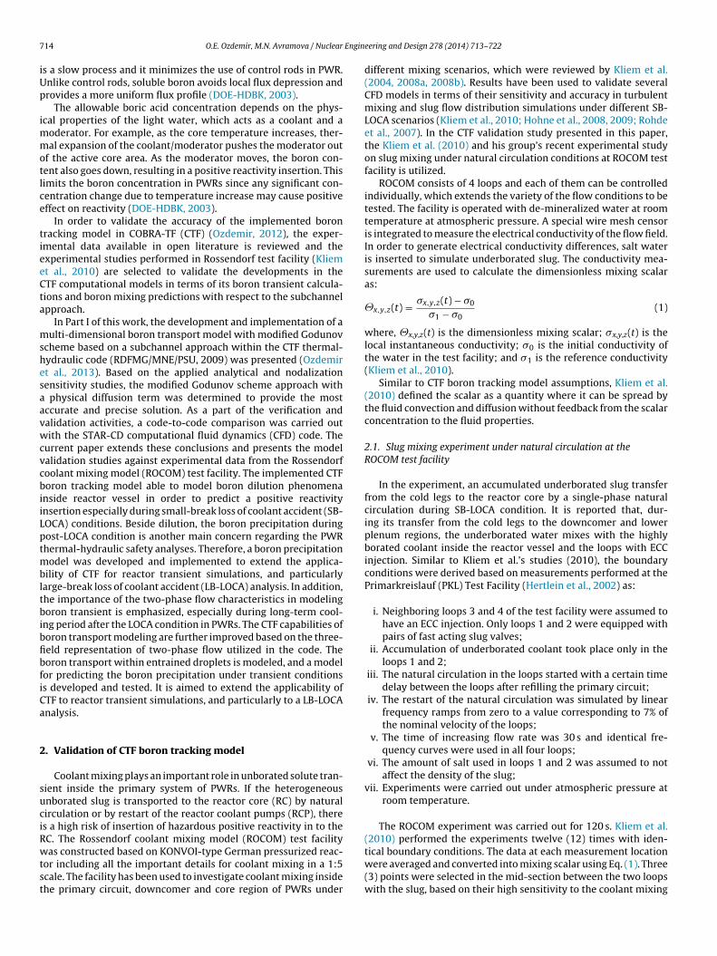
7 Engin
iUp
immotlce
tieeCta
mshesaavwcvcbiiLptmbltbibfibfiCa
2
suciRwtst
14 O.E. Ozdemir, M.N. Avramova / Nuclear
s a slow process and it minimizes the use of control rods in PWR.nlike control rods, soluble boron avoids local flux depression androvides a more uniform flux profile (DOE-HDBK, 2003).
The allowable boric acid concentration depends on the phys-cal properties of the light water, which acts as a coolant and a
oderator. For example, as the core temperature increases, ther-al expansion of the coolant/moderator pushes the moderator out
f the active core area. As the moderator moves, the boron con-ent also goes down, resulting in a positive reactivity insertion. Thisimits the boron concentration in PWRs since any significant con-entration change due to temperature increase may cause positiveffect on reactivity (DOE-HDBK, 2003).
In order to validate the accuracy of the implemented boronracking model in COBRA-TF (CTF) (Ozdemir, 2012), the exper-mental data available in open literature is reviewed and thexperimental studies performed in Rossendorf test facility (Kliemt al., 2010) are selected to validate the developments in theTF computational models in terms of its boron transient calcula-ions and boron mixing predictions with respect to the subchannelpproach.
In Part I of this work, the development and implementation of aulti-dimensional boron transport model with modified Godunov
cheme based on a subchannel approach within the CTF thermal-ydraulic code (RDFMG/MNE/PSU, 2009) was presented (Ozdemirt al., 2013). Based on the applied analytical and nodalizationensitivity studies, the modified Godunov scheme approach with
physical diffusion term was determined to provide the mostccurate and precise solution. As a part of the verification andalidation activities, a code-to-code comparison was carried outith the STAR-CD computational fluid dynamics (CFD) code. The
urrent paper extends these conclusions and presents the modelalidation studies against experimental data from the Rossendorfoolant mixing model (ROCOM) test facility. The implemented CTForon tracking model able to model boron dilution phenomena
nside reactor vessel in order to predict a positive reactivitynsertion especially during small-break loss of coolant accident (SB-OCA) conditions. Beside dilution, the boron precipitation duringost-LOCA condition is another main concern regarding the PWRhermal-hydraulic safety analyses. Therefore, a boron precipitation
odel was developed and implemented to extend the applica-ility of CTF for reactor transient simulations, and particularly
arge-break loss of coolant accident (LB-LOCA) analysis. In addition,he importance of the two-phase flow characteristics in modelingoron transient is emphasized, especially during long-term cool-
ng period after the LOCA condition in PWRs. The CTF capabilities oforon transport modeling are further improved based on the three-eld representation of two-phase flow utilized in the code. Theoron transport within entrained droplets is modeled, and a modelor predicting the boron precipitation under transient conditionss developed and tested. It is aimed to extend the applicability ofTF to reactor transient simulations, and particularly to a LB-LOCAnalysis.
. Validation of CTF boron tracking model
Coolant mixing plays an important role in unborated solute tran-ient inside the primary system of PWRs. If the heterogeneousnborated slug is transported to the reactor core (RC) by naturalirculation or by restart of the reactor coolant pumps (RCP), theres a high risk of insertion of hazardous positive reactivity in to theC. The Rossendorf coolant mixing model (ROCOM) test facility
as constructed based on KONVOI-type German pressurized reac-or including all the important details for coolant mixing in a 1:5cale. The facility has been used to investigate coolant mixing insidehe primary circuit, downcomer and core region of PWRs under
eering and Design 278 (2014) 713–722
different mixing scenarios, which were reviewed by Kliem et al.(2004, 2008a, 2008b). Results have been used to validate severalCFD models in terms of their sensitivity and accuracy in turbulentmixing and slug flow distribution simulations under different SB-LOCA scenarios (Kliem et al., 2010; Hohne et al., 2008, 2009; Rohdeet al., 2007). In the CTF validation study presented in this paper,the Kliem et al. (2010) and his group’s recent experimental studyon slug mixing under natural circulation conditions at ROCOM testfacility is utilized.
ROCOM consists of 4 loops and each of them can be controlledindividually, which extends the variety of the flow conditions to betested. The facility is operated with de-mineralized water at roomtemperature at atmospheric pressure. A special wire mesh censoris integrated to measure the electrical conductivity of the flow field.In order to generate electrical conductivity differences, salt wateris inserted to simulate underborated slug. The conductivity mea-surements are used to calculate the dimensionless mixing scalaras:
�x,y,z(t) = �x,y,z(t) − �0
�1 − �0(1)
where, �x,y,z(t) is the dimensionless mixing scalar; �x,y,z(t) is thelocal instantaneous conductivity; �0 is the initial conductivity ofthe water in the test facility; and �1 is the reference conductivity(Kliem et al., 2010).
Similar to CTF boron tracking model assumptions, Kliem et al.(2010) defined the scalar as a quantity where it can be spread bythe fluid convection and diffusion without feedback from the scalarconcentration to the fluid properties.
2.1. Slug mixing experiment under natural circulation at theROCOM test facility
In the experiment, an accumulated underborated slug transferfrom the cold legs to the reactor core by a single-phase naturalcirculation during SB-LOCA condition. It is reported that, dur-ing its transfer from the cold legs to the downcomer and lowerplenum regions, the underborated water mixes with the highlyborated coolant inside the reactor vessel and the loops with ECCinjection. Similar to Kliem et al.’s studies (2010), the boundaryconditions were derived based on measurements performed at thePrimarkreislauf (PKL) Test Facility (Hertlein et al., 2002) as:
i. Neighboring loops 3 and 4 of the test facility were assumed tohave an ECC injection. Only loops 1 and 2 were equipped withpairs of fast acting slug valves;
ii. Accumulation of underborated coolant took place only in theloops 1 and 2;
iii. The natural circulation in the loops started with a certain timedelay between the loops after refilling the primary circuit;
iv. The restart of the natural circulation was simulated by linearfrequency ramps from zero to a value corresponding to 7% ofthe nominal velocity of the loops;
v. The time of increasing flow rate was 30 s and identical fre-quency curves were used in all four loops;
vi. The amount of salt used in loops 1 and 2 was assumed to notaffect the density of the slug;
vii. Experiments were carried out under atmospheric pressure atroom temperature.
The ROCOM experiment was carried out for 120 s. Kliem et al.(2010) performed the experiments twelve (12) times with iden-
tical boundary conditions. The data at each measurement locationwere averaged and converted into mixing scalar using Eq. (1). Three(3) points were selected in the mid-section between the two loopswith the slug, based on their high sensitivity to the coolant mixing
O.E. Ozdemir, M.N. Avramova / Nuclear Engineering and Design 278 (2014) 713–722 715
Table 1ROCOM axial downcomer geometric properties.
Outer diameter (m) 1Inner diameter (m) 0.87Measurement height (m) 0.93Flow area (m2) 0.1909
Table 2CTF downcomer model geometric properties.
Number of subchannels 16Flow area (m2) 0.0119Wetted surface (m) 0.3672Gap width (m) 0.0650Gap length (m) 0.1836
fRt
2
wbusps
tagwtdidmtlilfl
iewfst(rc
i
taR
Table 3CTF downcomer model boundary conditions.
Maximum inlet flow rate (kg/s) 5.08
Total axial node number 30Axial node length (m) 0.031
rom both sides. Following the given experimental parameters, theOCOM experiment was simulated with CTF to validate its boronracking model, and the numerical modeling is discussed in details.
.2. Numerical modeling of ROCOM experiment with CTF
The downcomer section of the ROCOM test facility was modeledith CTF. The aim of this validation study was to compare the
oron tracking model predictions to the measured data, and to eval-ate the model sensitivity to the cross-flow mechanisms withinubchannel approach. The boundary conditions and the geometricarameters were conducted based on the Kliem et al. (2010) studyummarized in Section 2.1.
For the downcomer simulations in CTF, the geometry of the reac-or vessel, shown in Fig. 1(a), was simplified. According to the givenxial donwcomer measurement grid (Kliem et al., 2010) and theeometric parameters (Table 1), an annular geometry was used,hich consisted of sixteen (16) equivalent subchannels, connected
o each other by fifteen (15) lateral connections (gaps). The CTFowncomer model geometric parameters are listed in Table 2. Sim-
lar to the measurement grid, 0.93 m long uniform cross-sectionalowncomer region was divided into thirty (30) equivalent volu-etric cells, each of them having 31 mm node size. According to
he ROCOM test facility’s geometric specifications, the four coldegs connection to upper downcomer regions were defined as thenlet boundary conditions, as shown in Fig. 1(b). Based on the coldeg cross-section and given velocity ramp profile, the inlet massow rate profile was calculated.
It is important to point out that CTF have been developed tonvestigate thermal-hydraulic analysis of fuel bundle geometriesspecially during LOCA conditions. Based on the code structure,hich performs bottom to top calculations, it is not usual to per-
orm a downcomer simulation in CTF. Therefore, unlike reactor coreimulations, pressure inlet and pressure outlet boundary condi-ions were applied to generate a fluid profile flowing downwardfrom top to bottom) of the downcomer region. To achieve a velocityamp profile given in the Kliem et al.’s study (2010), the boundaryonditions were set as the following sequence:
i. Based on well-known Bernoulli’s principle, a 0.003 bars pressuredifference was set between inlet and outlet regions.
i. The transient was started by increasing the pressure differencelinearly until the desired maximum mass flow rate was obtainedand then it was kept constant.
Based on the given sequence and using the boundary condi-ions tabulated in Table 3, linear mass flow rate ramp profiles werechieved at all loop connections with upper downcomer region.esults were compared with the ROCOM loop mass flow rate, which
Fluid temperature (◦C) 20Operation pressure (atm) 1
was obtained by velocity ramp profile given by Kliem et al. (2010).As it can be seen in Fig. 2(a), in the CTF calculations, a time delaywas observed while the mass flow rate reached its maximum value.
After initializing the flow field at zero flow rate (−10 < t < 0), thetransient was started as 20 ◦C single-phase water injection from theloop connections with upper downcomer region; i.e. subchannels2, 8, 10 and 16 (as shown in Fig. 1(b)). When t = 20 s, the mixingscalar curve was started to the connections with the downcomerintroduced at loops 1 and 2 (subchannel 8 and 10), representing theunderborated water slug. Following the experiment, the slug pro-files were extracted at three positions in the mid-section betweenthe two loops 1 and 2, i.e. in subchannel 9. The measurement pos-itions were kept the same as given in the Kliem et al.’s study (2010).
2.3. Results and discussion
Four loops ROCOM test facility was simplified to annular down-comer geometry, where measurement grids were placed in theexperimental setup. Based on given flow rate and underboratedwater mixing scalar measurements at the exit of the cold leg noz-zles, the CTF simulations were compared with the experimentaldata extracted from Kliem et al. (2010) using the Plot Digitizersoftware. In this study, CTF is intended to model only the axialdistribution of the boron mixing scalar along experimental mea-surement points. According to the model assumptions the obtainedresults were compared as follows:
- The 0.25 m of the upper downcomer region, where the horizontalcold leg outlet flow enters to the vertical downcomer area, wasnot taken into account in the CTF calculations. As it was men-tioned earlier, the given ramp-flow profile and the mixing scalarswere measured at cold leg outlet nozzles. When approximatingthese values as inlet boundary conditions in the CTF simulationsas shown in Fig. 2, changes in the flow field from horizontal to ver-tical direction and its mixing effect were not considered. Since thenatural circulation case was studied, this effect was assumed to besmall. In the view of this assumption, CTF simulations were per-formed and comparisons between the CTF boron mixing scalarcalculations and the ROCOM measurements at three elevationsare presented in Fig. 3. As the flow reaches to the lower don-wcomer region, boron mixing scalar transition started earlierthan the experimental measurements. The reasons for this earlychange in the CTF results can be given as a result of the geometricassumptions and the simplification of the subchannel approachfor simulating complex 3-D flow patterns.
- The mixing scalar profile from ROCOM experiment was used tosimulate the underborated water in CTF calculations. Even thoughthe initial flow rates and boron mixing scalar were set as zero insubchannel 9, a continuous zero mixing scalar insertion from itsupper boundary level was observed while flow is developing. Asa result, the calculated mixing scalars in CTF were obtained verysmall. In order to distribute the results between 0 and 1 and tocompare on the same plot with the ROCOM data, the maximumvalue at the measurement points were used as their reference.In other words, the CTF results were renormalized based on the
maximum data point.- Beside its earlier transition in time, the oscillatory behavior inthe solute mixing results was observed. As shown in Fig. 3, whilethe slug moves down to the lower plenum, its mixing profile

716 O.E. Ozdemir, M.N. Avramova / Nuclear Engineering and Design 278 (2014) 713–722
Fig. 1. ROCOM reactor vessel (a), CTF model (b).
of the
Fig. 2. CTF boundary conditions of inlet mass flow rate (a) and time historyfluctuates more than the upper downcomer region. These phys-ical oscillations should not be confused with the numericalstability of the solution. The modified Godunov model eliminatesthe numerical diffusion due truncation errors as it was shown in
the first part of this study (Ozdemir et al., 2013). The transientvariations within the inlet boundary conditions can be given asthe main reason for these oscillations. It generates highly dis-persive cross-flow between each subchannel connection, whichmixing scalar at the loops 1 and 2 inlet (b) vs. ROCOM experimental data.
causes not only sudden changes in the results but also increasesthe spurious mixing along the flow path.
3. Boron precipitation model in CTF
The developed boron tracking model considers the risk ofboron dilution phenomena inside the reactor vessel in order topredict a positive reactivity insertion especially during SB-LOCA

O.E. Ozdemir, M.N. Avramova / Nuclear Engineering and Design 278 (2014) 713–722 717
ts at:
cpsspCa
ttit(to(i
aacT(amc
1
Fig. 3. CTF boron mixing scalar vs. ROCOM measuremen
onditions. Besides dilution, the boron precipitation duringost-LOCA condition is another main safety concern and corre-pondingly a modeling challenge in the PWR thermal-hydraulicafety analyses. Therefore, under the scope of this study, a boronrecipitation model was included to extend the applicability ofTF to reactor transient simulations, and particularly to LB-LOCAnalyses.
The post-LOCA long-term cooling period can be defined as theime period between the time when the core is reflooded and theime when the plant is secured. For the nuclear safety standards, its required to maintain the core cooling system intact during long-erm cooling period in order to reach the cold shut down conditionLou, 2008). In post-LOCA long-term cooling phase, there is a riskhat water might boil in the reactor for an extended time. Since theutflowing steam can only carry very low boric acid concentrationabout 1% of the water), boiling increases boric acid concentrationn the core (Tuunanen et al., 1988, 1994).
All US PWR designs (Westinghouse, Combustion Engineering,nd Babcock & Wilcox) use boron to control the core reactivity,nd they all report concerns about the boron precipitation espe-ially during the long-term cooling period after LOCA conditions.herefore all three designs have Emergency Core Cooling SystemsECCS) with active core dilution mechanisms to control the boriccid concentration and avoid precipitation (Brown et al., 2009). Twoain scenarios that may initiate precipitation during post-LOCA
ondition can be given as:
. Loss of ECCS recirculation due to debris generation and sumpscreen blockage;
upper (a), middle (b) and lower (c) downcomer regions.
2. Loss of cooling capability due boron precipitation inside reactorvessel.
Huh et al. (2008) reported the containment recirculation sumpblockage as an important reason for the increase in core temper-ature, which may cause water boil-off at certain core regions. Itis essential to measure the boron precipitation inside the core ifthe boron mass fraction reaches boron precipitation criteria due towater boiling. In addition to the decrease of the water level andthe boiling off condition, the solubility of the boric acid can beaffected by the chemical composition of the post-LOCA sump envi-ronment. In order to control the coolant pH level, buffer agents suchas sodium hydroxide (NaOH) and tri-sodium phosphate (TSP) areadded in the sump, which generates oxide corrosion products andincreases the risk of precipitation formation due chemical reactionswith other dissolved materials (Kim et al., 2008).
Comparing to boron dilution transient phenomena, the boronprecipitation did not receive the same level of attention, and exper-imental studies are limited. It is vital to have more analysis tounderstand sump debris and chemical effects on the performance ofECC systems on the long-term cooling period as well as their impacton the precipitation formation, mixing and transport phenomenonin the reactor vessel (Brown et al., 2009).
In order to model the boric acid dilution in the post-LOCAscenarios, the common approaches are limited by the simpli-
fied methods and conservative boundary conditions. However, amore complicated boric acid transport and mixing mechanismexists inside the reactor during post-LOCA conditions. In order toprovide guidance for developing new and more advance models,
7 Engineering and Design 278 (2014) 713–722
Pmtri
1
2
3
blcitbPecog
prTmtcildt1
(meitat
maetCiwtmBtt
cb
18 O.E. Ozdemir, M.N. Avramova / Nuclear
henomena Identification and Ranking Tables (PIRT) for boric acidixing, transport and precipitation modes were prepared by Wes-
inghouse Electric Company (Brown et al., 2009). According to thiseport, the precipitation process in the reactor vessel can be definedn three main steps:
. Formation of chemical solution outside the reactor vessel priorto a LOCA event, i.e. chemical formation of sump debris effectwhich are discussed in the previous section.
. Distribution and accumulation of the solute within the reactorvessel are defined in the Mixing/Transport PIRT tables.
. Super-saturation (due to boiling, evaporation or cooling of chem-ical solution) and formation of solid phase within the chemicalsolution on the surface within the reactor vessel, which areaddressed in the PIRT tables of Precipitation Modes.
Current and previous boron precipitation models are usuallyased on the assumption of “bulk” (i.e. total mixing volume)
imiting approach, which is predicted by the boric acid solubilityurves with respect to the temperature. However, recent test stud-es showed that the bulk precipitation model cannot be applied dueo existence of non-uniform temperatures and non-equilibriumoron concentration inside the reactor core. In the Westinghouserecipitation Modes PIRT, Brown and his colleagues described sev-ral types of precipitation states based on different two-phase flowonditions such as super-saturation due to the boiling/evaporationr cooling, liquid entrainment/de-entrainment, and precipitationrowth on surfaces and materials.
Mixing and precipitation of boric acid during long-term coolingeriod of LOCA scenarios in the Loviisa VVER-440 type of nucleareactor were studied within REWET-II and VEERA test facilities byuunanen et al. and his group (Tuunanen et al., 1988, 1994). Theain objectives of the experiments were to investigate the crys-
allization of boric acid inside reactor core and its effects on coreooling in terms of flow blockage of the rod bundles, overheat-ng and failure of fuel rods. It was reported that when the waterevel in the reactor is lower than the hot leg nozzles under limitedroplet entrainment field and low-pressure condition, precipita-ion is favorable near the collapsed water level (Tuunanen et al.,994).
In both the Westinghouse Precipitation Modes PIRT ReportBrown et al., 2009) and Tuunanen et al. and his group experi-
ental studies (Tuunanen et al., 1988, 1994), the importance ofntrained droplet field was highlighted in boric acid transport, mix-ng and precipitation analysis of two-phase flow. Therefore, withhe help of advanced two-phase three-field approach of CTF, it isimed to simulate the entrainment droplet field effect in the boronransportation during LOCA conditions.
For axial and transverse directions, CTF solves a set of threeomentum equations for the vapor phase, continuous liquid phase,
nd entrained liquid phase respectively. This allows the liquid andntrained droplets fields to flow with individual velocities rela-ive to the vapor phase (Avramova, 2007). Using this capability ofTF, boron transient within the entrained droplet field is calculated
n both axial and transverse directions. In order to be consistentith continuous liquid transport calculations described in Part I of
he presented study (Ozdemir et al., 2013), the same method, i.e.odified Godunov model, and cross-flow mechanisms are used.
y doing so, boron tracking model capabilities are extended andhe amount of boron transfer by the droplets field is included in
ransient calculations.Additionally, it was intended to predict the plated out soluteoncentration in CTF. As it was stated in the previous studies, solu-ility of boron increases with the increase of coolant temperature.
Fig. 4. CTF maximum boric acid concentration by Kim et al.’s correlation.
Thus, it was essential to take into account the coolant temperatureeffect in maximum boron concentration calculations:
i. First the maximum solubility of the boric acid in 100 g of water(maximum mass fraction mmax) is calculated according to Kimet al. correlation (Kim et al., 2008) as:
mmax
100= · exp
(− 2.68 × 10³
273.15 + Tliq+ 6.04
)(2)
where the conversion parameter is given as:
= (3.432 × 10²) · (� + 1.80 × 10⁻³ × Tliq) (3)
� = 0.1795 and Tliq is the liquid temperature in ◦C.ii. Then, the maximum boron concentration is evaluated based
on the amount of liquid mass (mliq) both in continuous andentrained droplet liquid phases:
�b max = mb max
mliq + mb max(4)
Kim et al. solubility correlation was derived in a temperaturerange between 40 and 160 ◦C (313–433 K) including the effectsof buffer agents (tri-sodium phosphate (TPT)), which generateparticulate oxide corrosion products and increase the risk of pre-cipitation by chemical reactions with other dissolved materials(Kim et al., 2008).
In CTF, if the liquid temperature reaches higher value than givenrange, the value at 160 ◦C is used. If the new solute density goesbeyond the maximum value, CTF assumes the excess is precipitatedand the solute density reaches its maximum value. The maximumboron concentration profile used in CTF is given in Fig. 4.
4. 2 × 2 multiple subchannel rod bundle two-phase teststudy
In order to validate the improvements in the CTF boron trackingmodel in terms of entrained droplet field and precipitation modelperformance, assessment studies were performed on a mini 2 × 2rod bundle (Ozdemir et al., 2013). Results for corner subchannels(subchannels 1 and 3) are represented in blue, the side subchan-nels (subchannels 2 and 8) are represented in red and the centralsubchannel (subchannel 5) is represented in green color to havea better demonstration of the results. In Fig. 5, the cross-sectionalgeometry of subchannels is illustrated, and the geometric parame-ters with initial conditions are summarized in Table 4.
The first study case was focused on verifying the consistency ofthe implemented entrained droplet field in the boron tracking cal-culations. The transient was started as the 486 K single-phase waterinjection with total mass flow rate of 0.618 kg/s was inserted from
O.E. Ozdemir, M.N. Avramova / Nuclear Engineering and Design 278 (2014) 713–722 719
Table 4Subchannel geometric parameters and initial conditions of 2 × 2 rod bundle.
Subchannel type Area [m2] Perimeter [m] Dh [m] Cb [ppm] Rein [–]
Corner (1, 3, 7, 9) 5.52e−5 0.0283
Side (2, 4, 6, 8) 1.17e−4 0.0415Internal (5) 1.87e−4 0.0455
tscaicSrm
the subchannels. The inlet flow rate was decreased linearly to 0.1
Fig. 5. Cross-sectional area of 2 × 2 rod bundle.
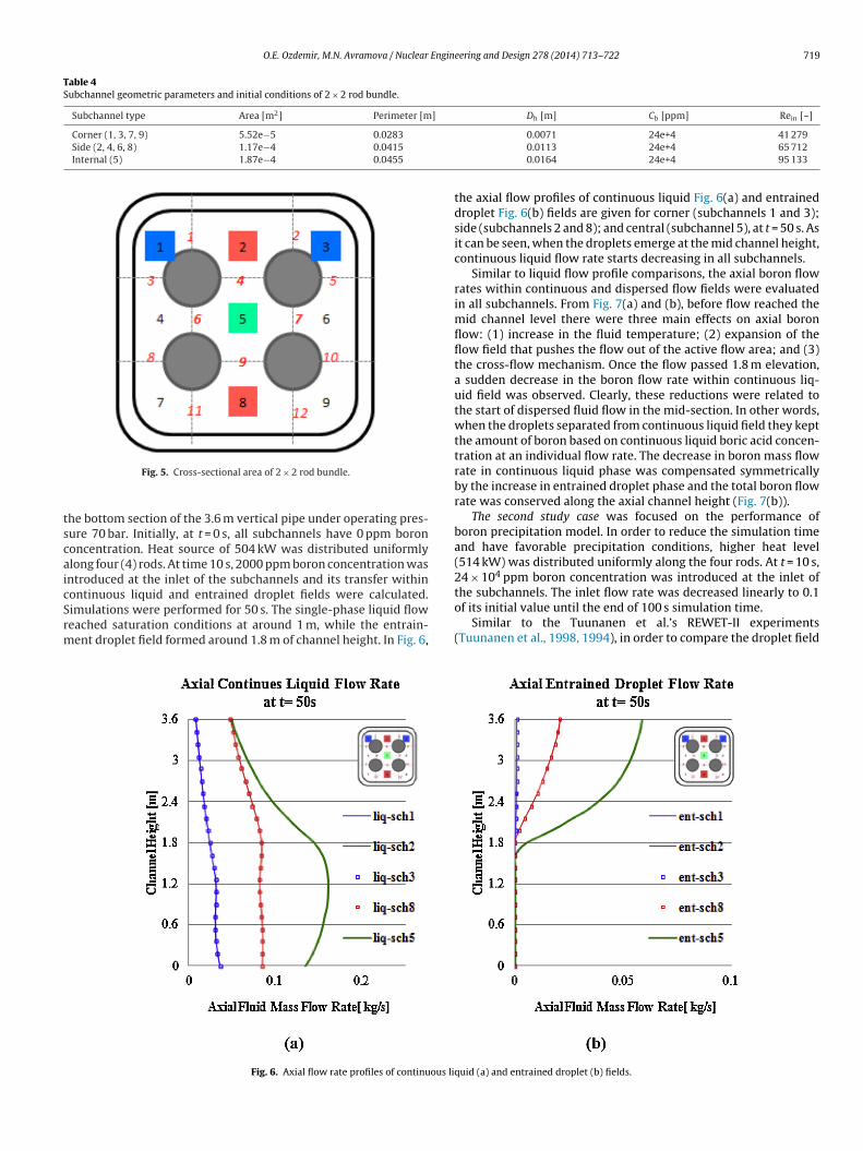
he bottom section of the 3.6 m vertical pipe under operating pres-ure 70 bar. Initially, at t = 0 s, all subchannels have 0 ppm borononcentration. Heat source of 504 kW was distributed uniformlylong four (4) rods. At time 10 s, 2000 ppm boron concentration wasntroduced at the inlet of the subchannels and its transfer withinontinuous liquid and entrained droplet fields were calculated.
imulations were performed for 50 s. The single-phase liquid floweached saturation conditions at around 1 m, while the entrain-ent droplet field formed around 1.8 m of channel height. In Fig. 6,Fig. 6. Axial flow rate profiles of continuous li
0.0071 24e+4 41 2790.0113 24e+4 65 7120.0164 24e+4 95 133
the axial flow profiles of continuous liquid Fig. 6(a) and entraineddroplet Fig. 6(b) fields are given for corner (subchannels 1 and 3);side (subchannels 2 and 8); and central (subchannel 5), at t = 50 s. Asit can be seen, when the droplets emerge at the mid channel height,continuous liquid flow rate starts decreasing in all subchannels.
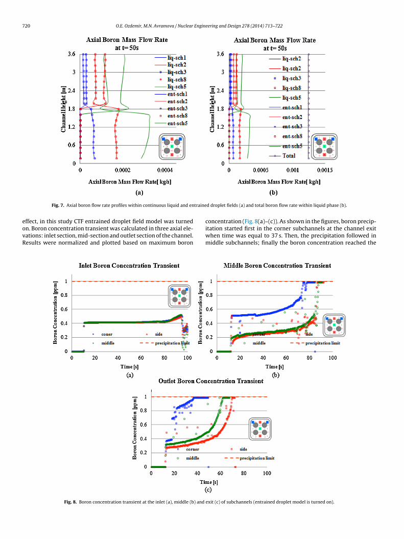
Similar to liquid flow profile comparisons, the axial boron flowrates within continuous and dispersed flow fields were evaluatedin all subchannels. From Fig. 7(a) and (b), before flow reached themid channel level there were three main effects on axial boronflow: (1) increase in the fluid temperature; (2) expansion of theflow field that pushes the flow out of the active flow area; and (3)the cross-flow mechanism. Once the flow passed 1.8 m elevation,a sudden decrease in the boron flow rate within continuous liq-uid field was observed. Clearly, these reductions were related tothe start of dispersed fluid flow in the mid-section. In other words,when the droplets separated from continuous liquid field they keptthe amount of boron based on continuous liquid boric acid concen-tration at an individual flow rate. The decrease in boron mass flowrate in continuous liquid phase was compensated symmetricallyby the increase in entrained droplet phase and the total boron flowrate was conserved along the axial channel height (Fig. 7(b)).
The second study case was focused on the performance ofboron precipitation model. In order to reduce the simulation timeand have favorable precipitation conditions, higher heat level(514 kW) was distributed uniformly along the four rods. At t = 10 s,24 × 104 ppm boron concentration was introduced at the inlet of
of its initial value until the end of 100 s simulation time.Similar to the Tuunanen et al.’s REWET-II experiments
(Tuunanen et al., 1998, 1994), in order to compare the droplet field
quid (a) and entrained droplet (b) fields.
720 O.E. Ozdemir, M.N. Avramova / Nuclear Engineering and Design 278 (2014) 713–722
traine
eovR
Fig. 7. Axial boron flow rate profiles within continuous liquid and en
ffect, in this study CTF entrained droplet field model was turned
n. Boron concentration transient was calculated in three axial ele-ations: inlet section, mid-section and outlet section of the channel.esults were normalized and plotted based on maximum boronFig. 8. Boron concentration transient at the inlet (a), middle (b) and
d droplet fields (a) and total boron flow rate within liquid phase (b).
concentration (Fig. 8(a)–(c)). As shown in the figures, boron precip-
itation started first in the corner subchannels at the channel exitwhen time was equal to 37 s. Then, the precipitation followed inmiddle subchannels; finally the boron concentration reached theexit (c) of subchannels (entrained droplet model is turned on).

O.E. Ozdemir, M.N. Avramova / Nuclear Engineering and Design 278 (2014) 713–722 721
) and
mitc
seTkvtai
wttiotdsat
5
mK
Fig. 9. Boron concentration transient at the inlet (a), middle (b
aximum value in side subchannels. Similar order was observedn the mid-section of the subchannels (Fig. 8(b)). At the inlet sec-ion, however, the boron concentration was conserved below theoncentration limit throughout the simulation.
Following similar approach in REWET-II experiments, a thirdtudy case was performed. It was assumed that the amount of thentrained droplet field was limited by using a moisture separator.herefore, the CTF entrained droplet model was turned off whileeeping the initial and boundary conditions identical with the pre-ious study case. By taking the same steps: the boron concentrationransient was calculated in three axial elevations: inlet, middlend outlet of the channel. The normalized results are presentedn Fig. 9(a)–(c), respectively.
Comparing to the case, in which the entrained droplet modelas activated in CTF (Fig. 6(a) and (b)), the boron concentration at
he exit and the mid-section of side and middle subchannels startedo increase from a higher level as shown in Fig. 9(a) and (b). Sim-lar to the REWET-II experimental results (Tuunanen et al., 1994),scillations, which were observed in the previous boron concentra-ion transient measurements, were eliminated when the entrainedroplet model was deactivated. As stated in the Tuunanen et al.’studies, a steady growth in boric acid concentration was observednd the precipitation was reported in the upper and mid part and ofhe rod bundle when the concentration exceeds saturation point.
. Conclusions
In Part II of the study on multi-dimensional boron transportodeling in subchannel approach, presented in this paper, the
liem et al.’s experimental study on slug mixing under natural
exit (c) of subchannels (entrained droplet model is turned off).
circulation conditions at the ROCOM test facility (2010) wasselected to assess the CTF results. Due to the lack of horizontal flowmodeling capabilities in CTF and the limitation in the availability inthe open literature parameters of the ROCOM test facility param-eters, simplifications were needed based on the model geometryand the boundary conditions. Two models were compared with theexperimental data. In both calculations, an earlier transition andunder predictions were observed in the CTF results, especially atlower downcomer regions where complex flow patterns exist dueflow expansion. With the ongoing horizontal flow model develop-ments in the CTF code, its modeling capabilities will be improvedin the future. This will provide more accurate knowledge of boronconcentration at the inlet and inside the reactor core for the coupledCTF/neutronics simulations.
CTF has the advantage of three-field representation of two-phase flow model, which allows liquid and entrained droplets fieldsto flow with individual velocities relative to the vapor phase. Simi-lar to previous improvements in boron tracking simulations withincontinuous liquid field as explained in Part I of the study (Ozdemiret al., 2013), axial and lateral boric acid transient within entraineddroplet field was calculated based on modified Godunov modeland cross-flow mechanisms. The multiple subchannel rod bundletest calculations demonstrated the consistent performance of theentrained droplet field under variety of geometrical and opera-tional conditions.
Boron precipitation model has been added to extend the
applicability of CTF for future reactor transient simulations, andparticularly to the LB-LOCA analysis. The importance of two-phaseflow characteristics in modeling boron transient was emphasized,especially during long-term cooling period after a LOCA condition
7 Engin
itomcae(ga
tooanit
A
pg
R
A
B
D
H
22 O.E. Ozdemir, M.N. Avramova / Nuclear
n PWRs. Based on available recourses in the literature, experimen-al analysis was reviewed, and the Kim et al.’s maximum solubilityf boron correlation (2008) was utilized in CTF boron trackingodel to predict the time and the location of the expected pre-
ipitation when the fluid starts to boil. The obtained results frompplications to test cases qualitatively agreed with the Tuunanent al.’s conclusions in REWET-II and VEERA experimental studies1988, 1994) – reducing the entrained droplet field caused a steadyrowth in boric acid concentration and a precipitation in the uppernd mid part of the rod bundle.
In summary, the CTF capabilities have been extended to modelhe boric acid transport, mixing and precipitation within continu-us and entrained droplet fields inside reactor vessel. With the helpf this novel approach, the CTF modeling features for LWR safetynd design analysis were extended. The CTF code became an alter-ative method to provide significantly faster and efficient analysis
n solute tracking in the core studies as compared to CFD basedhermal-hydraulic codes.
cknowledgments
This research project is being jointly carried out with and sup-orted by The Mitsubishi Heavy Industries, Ltd., Kobe, Japan by therant number 2/2011.
eferences
vramova, M., (Ph.D. thesis in nuclear engineering) 2007. Development of an Inno-vative Spacer Grid Model Utilizing Computational Fluid Dynamics Within aSubchannel Analysis Tool. The Pennsylvania State University, PA, United States.
rown, W.L., Kellerman, B.E., Fink, D.J., WCAP-17047-NP 2009. PhenomenaIdentification and Ranking Tables, (PIRT), Un-buffered/Buffered Boric Acid Mix-ing/Transport and Precipitation Modes in a Reactor Vessel During Post-LOCAConditions.
OE-HDBK, 2003. DOE Fundamentals Handbook, Nuclear Physics and Reactor The-ory, vols. 1 and 2. U. S. Department of Energy, Washington, DC, United States.
ertlein, R.J., Umminger, K., Prasser, H.-M., Hohne, T., Weiss, F.-P., 2002. Experimen-tal and numerical investigation of boron dilution transients in pressurized waterreactors. Nucl. Plant Oper. Control 141 (1), 88–107.
eering and Design 278 (2014) 713–722
Hohne, T., Kliem, S., Rohde, U., Weiss, F.-P, 2008. Boron dilution transients duringnatural circulations flow in PWR – experiments and CFD simulations. Nucl. Eng.Des. 238 (8), 1987–1995.
Hohne, T., Kliem, Vaibar, R., 2009. Experimental and numerical modeling of transi-tion matrix from momentum to buoyancy driven flow in a pressurized waterreactor. J. Eng. Gas Turbines Power 131 (1).
Huh, B.G., Bang, Y.S., Oh, D.Y., Kim, I.G., Woo, S.W., 2008. Analysis of post-LOCAlong term cooling performance and effect of recirculation flow. In: InternationalCongress on Advances in Nuclear Power Plants – ICAPP 2007, vol. 2, pp. 917–924.
Kim, Y.S.N.O., Lee, H.C., Yoo, E.H., Kim, S.H.H.M., 2008. High temperature boric acidsolubility during post-LOCA long-term cooling period. Trans. Am. Nucl. Soc. 99,489–490.
Kliem, S., Rohde, U., Weiß, F.-P., 2004. Core response of a PWR to slug of under-borated water. Nucl. Eng. Des. 230, 121–132.
Kliem, S., Prasser, H.-M., Suhnel, T., Weiss, F.-P., Hansen, A., 2008a. Experimentaldetermination of boron concentration distribution in the primary circuit of aPWR after a postulated cold leg small break loss-of-coolant-accident with coldleg safety injection. Nucl. Eng. Des. 238 (7), 1788–1801.
Kliem, S., Suhnel, T., Rohde, U., Hohne, T., Prasser, H.-M., Weiss, F.-P., 2008b. Exper-iments at the mixing test facility ROCOM for benchmarking of CFD codes. Nucl.Eng. Des. 238, 566–576.
Kliem, S., Hohne, T., Rohde, U., Weiss, F.-P., 2010. Experimentations on slug mixingunder natural circulation conditions at the ROCOM test facility using high-resolution measurement techniques and numerical modeling. Nucl. Eng. Des.240 (9), 2271–2280.
Lou, H., (M.S. thesis) 2008. Experimental Studies of Boric Acid Precipitation inNuclear Power Plants During the Post-LOCA Long-Term Cooling Period. KAIST.
Ozdemir, O.E., (Ph.D. thesis in nuclear engineering) 2012. Multi-dimensional BoronTransport Modeling in Subchannel Approach. The Pennsylvania State University,PA, United States.
Ozdemir, O.E., Avramova, M.N., Sato, K., 2013. Multi dimensional boron transportmodeling in subchannel approach: part I. Model selection, implementationand verification of COBRA-TF boron tracking model. Nucl. Eng. Des., http://dx.doi.org/10.1016/j.nucengdes.2013.02.031 (in press) RDFMG/MNE/PSU (2009).
Rohde, U., Hohne, T., Kliem, S., Hemstrom, B., Scheuerer, M., Toppila, T., Aszodi, A.,Boros, I., Farkas, I., Muhlbauer, P., Vyskocil, L., Klepac, J., Remis, J., Dury, T., 2007.Fluid mixing and flow distribution in a primary circuit of a nuclear pressurizedwater reactor – validation of CFD codes. Nucl. Eng. Des. 232 (15–17), 1639–1655.
Tuunanen, J., Kervinen, T., Kalli, H., Komsi, M., Tuomisito, H., Markkanen, E., 1988.Long-term emergency cooling experiments with aqueous boric acid solu-tion with the REWET-II and VEERA facilities. In: Proceedings of InternationalENS/ANS Conference on Thermal Reactor Safety, vol. 4, pp. 1428–1436.
Tuunanen, J., Tuomisito, H., Raussi, P., 1994. Experimental and analytical studies ofboric acid concentrations in a VVER-440 reactor during long-term cooling periodof loss-of-coolant accidents. Nucl. Eng. Des. 148, 217–231.
Wagner, J.C., 2003. Impact of soluble boron modeling for PWR burnup credit criti-cality safety analysis. Trans. Am. Nucl. Soc. 89, 120–122.


![Downlink Subchannel and Power Allocation in Multi-Cell ...prof.icc.skku.ac.kr/~dikim/paper/TW-Jul-10-1191.pdf[12], the authors solved a joint power and subchannel alloca-tion problem](https://img.dokumen.tips/doc/110x75/60f5004f2a0e605ce95c2639/downlink-subchannel-and-power-allocation-in-multi-cell-proficcskkuackrdikimpapertw-jul-10-1191pdf.jpg)