Embed Size (px)
Citation preview
14 · Multi-core Fiber for High-Capacity Long-Haul Spatially-Multiplexed Transmission
FEATURED TOPIC
1. Introduction
Data traffic is growing exponentially due to the emer-gence of various network services such as video streamingand smartphones. The transmission capacity of the opticalfiber has also been increasing exponentially due to the roll-outs of technologies such as wavelength-division multiplex-ing (WDM)*1 and the multi-level modulation*2; however,the capacity is rapidly approaching its fundamental limitdue to the depletion of the amplification bandwidth*3 andthe limit of signal-to-noise ratio (SNR) from nonlinearnoise*4(1),(2). Under these circumstances, space-division mul-tiplexing (SDM) has come to attract a lot of attention(2),(3).For further increasing fiber capacity, various researchgroups have been investigating SDM-related technologies.
For overcoming the capacity limit, we have been pro-moting research and development on multi-core fiber(MCF) toward practical use. Since the MCF includes theplurality of cores as shown in Fig. 1, characteristics degra-dations specific to the MCF structure, which were not ob-served in the conventional single-core fiber (SCF), areconcerns for the actualization of this technology. The inter-core crosstalk (XT) is one of the most important parame-ters in the MCF, and suppression of the XT is crucial fortransmitting signals independently on individual cores. We
proposed and experimentally validated a theoretical modelthat can predict the crosstalk and its statistical characteris-tics of actual MCFs(4)-(7), demonstrated that low loss andultra-low XT—necessary for long-haul transmission—canbe achieved in the fabricated MCF(6)-(8), theoretically re-vealed the behavior of the XT as a noise(8)-(10), and en-hanced the SNR of each core of the MCF based onconsidering the XT as a noise(11),(12), each for the first time.This paper reviews these major achievements of our re-search and development on the MCF.
2. Behavior of Inter-core Crosstalk
2-1 Theoretical prediction in earlier studiesEarlier studies(13)-(15) reported that the XT of the MCF
can be suppressed by inducing a slight difference in the ef-fective refractive indices (neffs) between cores, based ontheoretical considerations.According to these studies, theXT from Core m to Core n can be expressed by using thecoupled-mode equation(16):
........................ (1)
where An is the complex amplitude of the electric field ofCore n, κnm is the mode-coupling coefficient from Core mto Core n, βn = (2π/λ)neff,n is the propagation constant ofCore n, and z is the longitudinal position along the fiber.When only Core m is excited [Am(0) = 1], the power ofCore n can be derived as(16):
...................................................... (2)
........ (3)
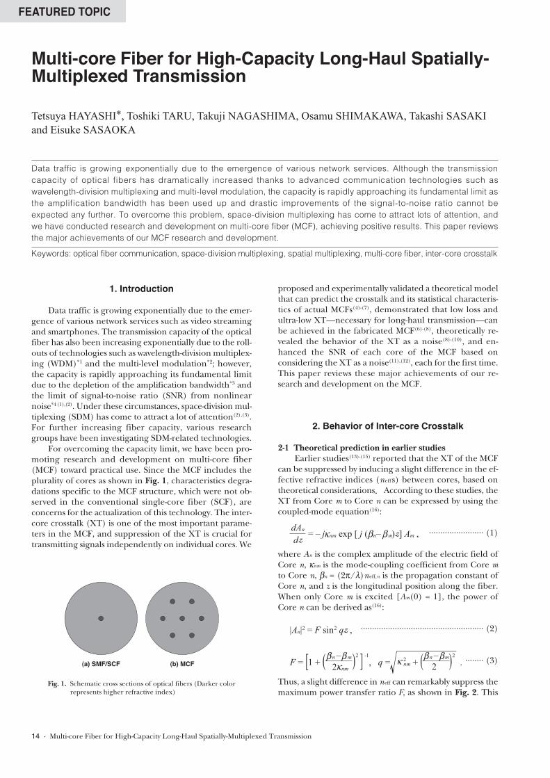
Thus, a slight difference in neff can remarkably suppress themaximum power transfer ratio F, as shown in Fig. 2. This
Multi-core Fiber for High-Capacity Long-Haul Spatially-Multiplexed Transmission
Tetsuya HAYASHI*, Toshiki TARU, Takuji NAGASHIMA, Osamu SHIMAKAWA, Takashi SASAKI
and Eisuke SASAOKA
(a) SMF/SCF (b) MCF
Fig. 1. Schematic cross sections of optical fibers (Darker color represents higher refractive index)
dAndz
= – j nm exp [ j ( n– m)z] Am ,βκ β
|An|2 = F sin2 qz ,
F = [1 + ( , q = 2nm + ( .
n– m2 nm
β βκ κ) ]2 n– mβ β ) 2-1
2
Data traffic is growing exponentially due to the emergence of various network services. Although the transmissioncapacity of optical fibers has dramatically increased thanks to advanced communication technologies such aswavelength-division multiplexing and multi-level modulation, the capacity is rapidly approaching its fundamental limit asthe amplification bandwidth has been used up and drastic improvements of the signal-to-noise ratio cannot beexpected any further. To overcome this problem, space-division multiplexing has come to attract lots of attention, andwe have conducted research and development on multi-core fiber (MCF), achieving positive results. This paper reviewsthe major achievements of our MCF research and development.
Keywords: optical fiber communication, space-division multiplexing, spatial multiplexing, multi-core fiber, inter-core crosstalk
is because the slight difference in neff can induce a largedifference in β in conditions of λ ~ 10−6, and the large vari-ation of the phase difference along the MCF—the phasemismatch— inhibits efficient mode couplings.
2-2 Effect of fiber bend on the crosstalkHowever, the above discussion is based on the simple
coupled-mode theory that assumes ideal conditions wherethe cores are not longitudinally perturbed, and thus wasanticipated to be inapplicable to actual MCFs, which arelongitudinally perturbed by various internal and externalfactors. We speculated that the fiber bend should have aparticularly large effect on the XT, and therefore investi-gated the effect theoretically and experimentally(4).
Based on the equivalent index model(17), which hasbeen widely used in loss analysis of bent waveguides, a bentfiber can be described as a corresponding straight fiberwhich has an equivalent refractive-index profile
.......................................... (4)
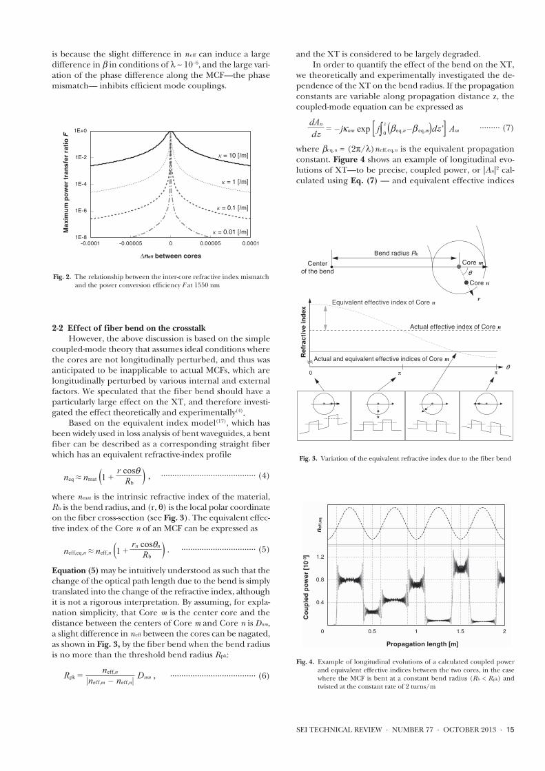
where nmat is the intrinsic refractive index of the material,Rb is the bend radius, and (r, θ) is the local polar coordinateon the fiber cross-section (see Fig. 3). The equivalent effec-tive index of the Core n of an MCF can be expressed as
................................. (5)
Equation (5)may be intuitively understood as such that thechange of the optical path length due to the bend is simplytranslated into the change of the refractive index, althoughit is not a rigorous interpretation. By assuming, for expla-nation simplicity, that Core m is the center core and thedistance between the centers of Core m and Core n is Dnm,a slight difference in neff between the cores can be nagated,as shown in Fig. 3, by the fiber bend when the bend radiusis no more than the threshold bend radius Rpk:
...................................... (6)
and the XT is considered to be largely degraded.In order to quantify the effect of the bend on the XT,
we theoretically and experimentally investigated the de-pendence of the XT on the bend radius. If the propagationconstants are variable along propagation distance z, thecoupled-mode equation can be expressed as
......... (7)
where βeq,n = (2π/λ)neff,eq,n is the equivalent propagationconstant. Figure 4 shows an example of longitudinal evo-lutions of XT—to be precise, coupled power, or |An|2 cal-culated using Eq. (7) — and equivalent effective indices
SEI TECHNICAL REVIEW · NUMBER 77 · OCTOBER 2013 · 15
1E-8
1E-6
1E-4
1E-2
1E+0
-0.0001 -0.00005 0 0.00005 0.0001
Max
imum
pow
er tr
ansf
er ra
tio F
∆neff between cores
κ = 10 [/m]
κ = 1 [/m]
κ = 0.01 [/m]
κ = 0.1 [/m]
Fig. 2. The relationship between the inter-core refractive index mismatch and the power conversion efficiency F at 1550 nm
0 0.5
0.4
0.8
1.2
1 1.5 2
Propagation length [m]
Coup
led
powe
r [10
-3]
n eff,
eq
Fig. 4. Example of longitudinal evolutions of a calculated coupled powerand equivalent effective indices between the two cores, in the casewhere the MCF is bent at a constant bend radius (Rb < Rpk) andtwisted at the constant rate of 2 turns/m
θCore m
r
Centerof the bend
Bend radius Rb
Core n
θ
Refra
ctiv
e in
dex
0 π π
Equivalent effective index of Core n
Actual and equivalent effective indices of Core m
Actual effective index of Core n
Fig. 3. Variation of the equivalent refractive index due to the fiber bend
neq ≈ nmat (1 + ,r cos )θRb
neff,eq,n ≈ neff,n (1 + .rn cos n )θRb
Rpk = Dnm ,neff,n
|neff,m – neff,n|
dAndz
= – j nm exp j∫ ( eq,n– eq,m)dz’ Amβκ βz
0[ ]

between the two cores, in the case where the MCF is bentat a constant bend radius (Rb < Rpk) and twisted at the con-stant rate of 2 turns/m. In contrast with the simple oscilla-tion shown in Eqs. (2) and (3), the XT changed dominantlyat every phase-matching point where the equivalent effec-tive indices are equal, and the changes appear random.Only little oscillations occurred in XT at positions otherthan the phase-matching points.
The reason why the dominant XT changes appear ran-dom is because the phase differences between the coresare different for each phase-matching point. In the calcu-lation, these random changes are deterministic; however,they are considered to be stochastic in practice because thephase differences can be easily fluctuated in practice byslight variations in the bending radius, twist rate of fiber,and so on. Therefore, to deal with such randomness of theXT, we conducted a Monte Carlo simulation by introduc-ing random phase shifts to Eq. (7), and investigated the re-lationship between the bend radius and statistical mean ofthe simulated XT. In addition, we evaluated a fabricatedMCF, and validated the above consideration and simula-tion method. Comparisons between the measured and thesimulated XT are shown in Fig. 5. Points represent the av-erages of ten measurements under the same conditions,and the MCF was rewound before each of the ten measure-ments. The error bars indicate the maximum and the min-imum of the measured values at each bend radius. Thesolid line represents the average of the simulated XT for600 instances. The measured and the simulated XT are ina good agreement. From these results, we revealed that themeasured XT can be predicted by the theoretical model.Fiber designs considering the effect of the bend are neces-sary for the XT suppression in MCFs(4).
2-3 The crosstalk of the homogeneous MCF Based on the previous section, it was found that the
XT can be suppressed if R b is adequately larger than Rpk,and large differences in the optical properties between thecores are required to shorten Rpk. On the other hand, it isunfavorable to pack different types of cores into an MCF
because the characteristics of every core of the MCF trans-mission lines need to be managed. Therefore, we pro-posed a low-XT homogeneous MCF, where all the coresare identical, by utilizing the bend for inducing the phasemismatch(5)-(8).
In this section, we review the derivation and validationof the analytical expressions of the statistical characteristicsof the XT of the homogeneous MCF, with which we caneasily design homogeneous MCFs.
If the bend perturbation is dominant, the XT dis-cretely changes at every phase-matching point, as shown inFig. 4. These XT changes can be approximated as discreteand random mode coupling:
.............. (8)
where An,N is the An after N-th phase-matching point, φ rnd,Nthe phase difference between the cores at N-th phase-matching point, and Knm,N the coupling coefficient fromCore m to Core n for the discrete change. The phase dif-ference φ rnd,N is a random number as we mentioned above.If only Core m is excited (Am,0 = 1, An,0 = 0), by assuming ad-equately low XT, the approximations of |An,N | << 1 and Am,N
≈ Am,0 = 1 hold, and the XT value X can be approximatedas |An,N |2. Thus, Eq. (8) can be approximated as
.............................. (9)
The probability density functions (PDFs) of ℜ[Κnmexp ( jφrnd)]and ℑ[Κnmexp( jφrnd)] are not normally distributed; how-ever, based on the central limit theorem, the PDFs ofℜ[An,N] and ℑ[An,N] can converge to a normal distribu-tion if N is large enough. With some assumptions, thevariance of ℜ[An,N]s and ℑ[An,N]s of the two polarizationmodes can be analytically derived as(7):
........................... (10)
where L is the fiber length. Since the sum of powers of lrandom numbers—whose PDFs are the standard normaldistribution— has the PDF of the chi-square distributionwith l degrees of freedom (df), the PDF of X (≈ |An,N |2 ={ℜ[An,N]}2 + {ℑ[An,N]}2) can be expressed as(7)
...................... (11)
and the mean value (mean XT) of X can be expressed as
..................... (12)
It can be found, from Eq. (12), that the XT can be sup-pressed by shortening the bend radius Rb. In decibels,99.99 percent of the XT distribution is µX + ~7.7 dB—theXT distribution on the decibel scale has the constant shapeindependent of µX.
The XT distribution expressed by Eq. (11) can bemeasured with the wavelength scanning method(8). The XTvalue X can be adequately dispersed by the randomizationof the phase difference between cores, thanks to the wave-length dependence of the propagation constant. A measuredXT spectrum is shown in Fig. 6, and the XT distribution ob-
16 · Multi-core Fiber for High-Capacity Long-Haul Spatially-Multiplexed Transmission
-60
-50
-40
-30
-20
-10
0 50 100 150
Cros
stal
k [d
B]
Bend radius Rb [mm]
Measured(average)
Simulated(staistical mean)
Rpk
Fig. 5. Example of the dependence of the crosstalk on the bend radius
An,N = An,N –1 – jKnm,N exp ( jφrnd,N) Am,N –1 ,
An,N ≈ – jΣKnm,l exp ( jφrnd,l) .N
l=1
4df ≈ 12
Rb
2 neff,nDnmσ κ2 nm L ,2 λ
π
f (X ) = exp – ,X )(σ 44df4
Xσ 2
4df2
µX,nm ≈ 4 L .σ Rb
πneff,nDnm
24df ≈ κ λ2
nm

tained from the data of Fig. 6 is shown in Fig. 7. It can beobserved that X heavily varied with wavelength and that theactual XT distribution is well fitted by Eq. (11).
3. Demonstration of Ultra-Low-Crosstalk Homogeneous MCF Feasible to
Long-Haul Transmission
We designed and fabricated a low-XT homogeneousMCF (MCF-A) by using Eqs. (11) and (12)(5)-(8).
Figure 8 shows a cross section of the fabricated MCF-A.The core pitch, the cladding diameter, and the coating di-ameter of MCF-A were 45 µm, 150 µm, and 256 µm, respec-tively. Table 1 shows the optical properties of each MCF-Acore. The transmission loss was 0.175–0.181 dB/km (avg.0.178 dB/km) at 1550 nm, and no more than 0.192–0.202dB/km in C+L band (1530–1625 nm), owing to the pure sil-ica core technology. Furthermore, no loss degradations wereobserved in the outer cores. Including other optical prop-erties, the fabricated MCF was suitable for C+L band trans-mission that is necessary for long-haul transmission.
Figure 9 shows the mean XT between neighboringcores of MCF-A, measured using the wavelength scanningmethod(8). The measurement results were in good agree-ment with Eq. (12). The averages of the mean XT µX were
as low as −79.5 dB at 1550 nm, and −69.7 dB at 1625 nm.Even µX from 6 outer cores to the center core (center-coreµX) was −72.3 dB at 1550 nm, and −62.1 dB at 1625 nm.
By using Eq. (12), the dependence of µX on the prop-agation length L and the bend radius Rb can be estimated,though the length and the bend radius of MCF-A was 17.4km and 140 mm, respectively. Figure 10 shows the relation-ship between the propagation length, the bend radius, andthe center-core µX of MCF-A at 1550 nm. The center-coreµX and the 99.99 percent of the XT can be less than −30dB, even after 10,000 km when Rb is less than ~4 m and~0.7 m respectively, and it was demonstrated for the firsttime that the XT of the MCF can be suppressed enoughfor ultra-long-haul transmission.
SEI TECHNICAL REVIEW · NUMBER 77 · OCTOBER 2013 · 17
0E+0
2E-7
4E-7
6E-7
8E-7
1620 1625 1630
Cros
stal
k X
Wavelength [nm]
Fig. 6. Example of the XT spectrum
0E+0
2E+6
4E+6
6E+6
8E+6
0E+0 1E-7 2E-7 3E-7 4E-7 5E-7 6E-7
Prob
abili
ty d
ensi
ty
Crosstalk X
MeasurementTheoretical fitting
Fig. 7. Example of the XT distribution
1
2
3
45
6
7
Marker
Fig. 8. A cross section of MCF-A
-85
-80
-75
-70
-65
1 2 3 4 5 6 7
Mea
n cr
osst
alk
[dB]
ID # of output core
1234567
ID# ofinputcore
λ = 1550 nm
λ = 1625 nm
µX calculated using Eq. (12)
Fig. 9. Mean crosstalk between neighboring cores of MCF-A after 17.4-km propagation
Table 1. Optical properties of cores of MCF-A
Transmissionloss [dB/km]
λcc
[nm]MFD[µm]
Aeff
[µm2]Disp.
[ps/(nm·km)]D. slope[ps/(nm2·km)]
λ [nm] 1550 1625 1550 1550 1550 1550
Avg. 0.178 0.198 1497 9.8 79.9 22.2 0.062
Min. 0.175 0.192 1483 9.7 78.2 22.1 0.062
Max. 0.181 0.202 1509 9.9 81.3 22.2 0.062

With this MCF, a transmission capacity of more than100 Tb/s per fiber was achieved, for the first time, in thetransmission experiment conducted by The National Insti-tute of Information and Communications Technology,among others(18), (19).
4. Effect of the Crosstalk on the TransmissionQuality
In the previous section, the target level of the XT wasset such that the 0.9999-quantile of the statistical distribu-tion should be less than −30 dB, after an earlier study(15),which set the target of the XT between neighboring coresas less than −30 dB. However, it was not necessarily basedon theoretical groundings, which should include the con-sideration of the behavior of the XT as a noise. Therefore,we considered the effect of the XT on the transmissionquality(9),(10), based on the stochastic behavior of the XT,which are described in the previous section.
Based on Section 2, the XT of the MCF stochasticallychanges with the time/wavelength variation of the phasedifference between the cores, and the I- and Q-compo-nents*5 of the two polarization modes of coupled light (XTlight) are normally distributed with the variance of µX/4.Like amplified spontaneous emission (ASE) noise(21) andnonlinear interference noise(22), XT can be regarded asa virtual additive white Gaussian noise when the band-width of the signal light is adequately broad, since theXT changes rapidly in the wavelength.
The Q -factor—that is, the most commonly used figureof the transmission quality— can be defined as(22):
..................................................... (13)
where µi and σi are the means and the standard deviations,respectively, of the neighboring constellation points.
The decibel value of the Q -factor can be expressed as
............................ (14)
Therefore, hereinafter, we will discuss the Q2-factor insteadof the Q -factor. If we assume σn = σ 1 = σ 2, and let S = |µ 1 −µ2|, the nearest distance between the constellation symbols,the Q 2-factor, can be expressed as
....................................................... (15)
When we consider the total mean XT µX,total from othercores, where the mean XT is defined as the average powerof the XT light divided by that of the signal power Ps, thevariance σ x2 of the XT light on the I–Q planes can be ex-pressed as
................................................. (16)
Since the variance of a sum of statistically independent vari-ables equals to the sum of the variances of the statisticallyindependent variables, the Q2-factor affected by the XT canbe expressed as
............................................... (17)
From Eqs. (15)–(17), XT-induced Q2-penalty (Qn2/Qx2) canbe expressed as
.... (18)
where Ps/S 2 is the value determined by the modulation for-mat. Values of Ps/S 2 for typical ideal modulation formatsare shown in Table 2. Figure 11 shows the XT-induced Q 2-penalty at Qx2 = 9.8 dB (bit-error rate BER = 1 × 10⁻³), whichwas calculated using Eq. (18). The XT-induced Q 2-penalty(Qn2/Q x2) can be suppressed to be less than 1 dB at Q x2 =9.8 dB if µX,total can be suppressed to be less than −16.7 dBfor PDM-QPSK, −23.7 dB for PDM-16QAM, and −29.9 dBfor PDM-64QAM.
This result revealed that signals modulated with ahigh-order modulation with a spectral efficiency (SE) of 10bit/s/Hz or more can be transmitted with no significantpenalty if µX,total is less than about −30 dB after the propa-gation of the total MCF link, and that MCF-A can transmitthe high-SE signals over ultra-long-haul (> 10,000 km) linksin terms of the XT.
18 · Multi-core Fiber for High-Capacity Long-Haul Spatially-Multiplexed Transmission
0.1
1
10
10 100 1,000 10,000
Propagation length L [km]
Bend
radi
us R
b [m
]
-30 dB-30 dB-30 dB
-35 dB-35 dB-35 dB
-40 dB-40 dB-40 dB
-45 dB-45 dB-45 dB
-50 dB-50 dB-50 dB
-55dB-55dB-55dB
-60 dB-60 dB-60 dB
-65 dB-65 dB-65 dB
-70 dB-70 dB-70 dB
-72.3 dB
Fig. 10. The relationship between the propagation length, the bend radius,and the mean XT µX to the center core of MCF-A at 1550 nm. Dia-mond: Rb and L where µX was measured. Contour lines representµX to the center core, estimated from the measurement values andEq. (12).
QdB = 20log10 Q = 10log10Q2 .
Qn = .S22
4σ 2n
x = Ps µX,total2
4σ .
Qx = .S22
4 ( + )σ 2n σ 2
x
= 1 + QnµX,total = 1 – QxµX,total . ,Qn
Qx
Ps
S2Ps
S222
– 1
2
2 ( )
Table 2. Values of Ps/S 2 for the typical modulation format
Modulation format Ps/S 2
PDM-QPSK 1
PDM-8PSK 21/2 / (21/2-1)
PDM-16QAM 5
PDM-32QAM 10
PDM-64QAM 21
PDM-128QAM 41
Q = |µ1–µ2| 1+ 2σ σ

5. Enhancement of SNR in MCF
Though the XT of MCF-A was confirmed to be ex-tremely low, the suppression of noises other than the XTis also very important for long-haul transmission.
Recently, owing to the actualization of digital coherentdetection, the phase information of light can be received,and linear distortions—such as the chromatic dispersion—can be compensated by digital signal processing. There-fore, the suppression of the ASE noise and the nonlinearinterference (NLI) noise has become one of the most im-portant issues for the SCF for high-capacity transmission(2),and a recent high-capacity transmission experiment hasemployed an SCF that has low loss for ASE noise suppres-sion and large effective area Aeff for NLI noise suppres-sion(23).
The XT of MCF-A was suppressed to an extremely lowlevel; however, the transmission loss was higher than thatof typical pure-silica-core SCF (≤ 0.17 dB/km)—though itwas lower than that of the standard SMF (SSMF) and thelowest in reported MCFs, and Aeff was not improved fromSSMF. Therefore, we proposed an MCF that can suppressthe ASE and NLI noises by lowering loss and enlarging Aeff
and can properly suppress the XT simultaneously(11),(12).5-1 Effect of crosstalk on SNR
For the single-core dispersion-uncompensated NyquistWDM*6 transmission system, SNR can be estimated usingclosed-form equations(21), and the maximum SNR achiev-able in the system (SNRSC: the SNR includes ASE and NLInoises but does not include XT) can be derived.
As described in Section 4, when the bandwidth of thesignal light is adequately broad, XT can be regarded as avirtual additive white Gaussian noise, similar to ASE andNLI noises. Accordingly, the maximum SNR achievable inthe multi-core system (SNRMC: the SNR includes ASE, NLI,and XT noises) can be derived(11),(12), by expanding theequations in Ref. (21). From the derived expressions, it wasfound that the XT-induced SNR penalty (SNRSC/SNRMC)is dependent on the noise figure F of optical amplifiers,the whole bandwidth BWDM of WDM, and the span length(interval of the amplifiers), but independent of the num-ber of spans, or (the length of transmission link) = (the
span length) × (the number of spans). This is because F,BWDM, and the span length affect the ratio of ASE/NLInoise increase per unit length to the XT increase per unitlength, but the number of spans does not affect the ratio.
Figure 12 shows the XT-induced SNR penalty in theMCF with SSMF cores (loss ~ 0.19 dB/km, Aeff ~ 80 µm2) ata wavelength of 1550 nm in the condition at the spanlength of 80 km. It was found that the SNR penalty beginsto drastically degrade when µX,total per one 80-km span ex-ceeds 10−4 (−40 dB), and that the effect of over suppressionof the XT is limited.
5-2 Fabrication of the low-loss large-Aeff low-XT MCFµX,total of MCF-A was about −66 dB at 1550 nm after 80-
km propagation, and it can be noted that the µX,total wassuppressed too much in terms of the suppression of the XT-induced SNR penalty. Thus, by relaxing the target of µX,total
such as less than −40 dB after 80-km propagation and lever-aging the relaxed margin for enlarging Aeff of each core,we designed and fabricated an MCF (MCF-B) that can si-multaneously achieve low loss, large Aeff, and low XT.
Figure 13 shows a cross-section of the fabricated MCF-
SEI TECHNICAL REVIEW · NUMBER 77 · OCTOBER 2013 · 19
0
1
2
3
4
5
6
7
-45 -40 -35 -30 -25 -20 -15 -10
Total mean XT from other cores (µX,total) [dB]
Q2 -p
enal
ty (Q
n2 / Q
x2 ) [dB
]
PDM-12
8QAM
PDM-12
8QAM
PDM-12
8QAM
PDM-64Q
AMPD
M-64Q
AMPD
M-64Q
AMPD
M-32Q
AMPD
M-32Q
AMPD
M-32Q
AMPD
M-16
QAM
PDM-16
QAM
PDM-16
QAM
PDM-8PS
KPD
M-8PS
KPD
M-8PS
K
PDM-QPS
KPD
M-QPS
KPD
M-QPS
K
Fig. 11. XT-induced Q 2-penalty at Qw/XT2 = 9.8 dB
0
0.5
1
1.5
2
2.5
3
3.5
-60 -55 -50 -45 -40 -35 -30
µX,total after one 80-km span [dB]
XT-in
duce
d SN
R-pe
nalty
[dB] F = 3 dB, BWDM = 5 THz
F = 3 dB, BWDM = 10 THz F = 4 dB, BWDM = 5 THzF = 4 dB, BWDM = 10 THzF = 5 dB, BWDM = 5 THzF = 5 dB, BWDM = 10 THzF = 6 dB, BWDM = 5 THzF = 6 dB, BWDM = 10 THz
Fig. 12. XT-induced SNR penalty in the MCF with SSMF cores (Aeff ~ 80µm2). (F : the noise figure of optical amplifier, BWDM: the wholebandwidth of WDM)
Marker
2
3
45
6
7
1
Fig. 13. A cross-section of MCF-B

B. Measured optical properties of MCF-B are shown inTable 3 and in Figs. 14 and 15. The transmission loss weachieved was 0.163–0.172 dB/km (average: 0.168 dB/km)at 1550 nm, and no more than 0.183–0.194 dB/km overthe whole C+L band, which are the lowest values amongthe reported MCFs. The Aeffs were 121–127 µm2 (average:124.1 µm2). The core pitch and the cladding diameter ofMCF-B were 51 µm and 188 µm. The µX between the neigh-boring cores were from −62.8 dB to −59.2 dB (average:−61.3 dB) for L = 6.99 km and Rb = 140 mm at λ = 1550nm, and the center-core µX was −53.1 dB. Accordingly, thecenter-core µX was estimated to be −42.5 dB after 80-kmpropagation.
5-3 SNR improvements of the fabricated MCFs fromstandard SMFFigure 16 shows the calculated results how the XT-
induced SNR penalty (SNRSC/SNRMC, shown as dash-dottedlines) and the SNR improvement (�SNRMC, shown as solidcurves) from the standard SMF depend on SNRSC and µX,total
after one span, for MCF-A and MCF-B (see Ref. (12) for thedetails of the calculations). The calculation assumed awhole WDM bandwidth of 10 THz, noise figure of ampli-fiers of 4 dB, and a span length of 80 km. The SNR improve-ment and penalty, represented by the contour lines, areindependent of the number of spans, as mentioned above.It can be seen that the SNR improvement by ASE/NLInoise suppression is cancelled if µX,total is larger than around−40 dB after 80-km propagation. It was confirmed that theSNR in each core was successfully improved in MCF-B bythe design change from MCF-A to MCF-B, which leveragedthe margin of the over suppressed XT of MCF-A for enlarg-ing Aeff (and by lowering loss). Thus, it was revealed thatbalanced improvements of Aeff, transmission loss, and XTare important. The balance of Aeff and XT is especially im-portant because Aeff enlargement weaken the power con-finements into cores.
6. Conclusion
We reviewed the major achievements of our researchand development on the MCF. By investigating the behav-ior of the inter-core crosstalk (XT)—which does not occurin the conventional single-core fiber— in detail, we pro-posed and validated the simulation model that can predictthe XT of actual MCFs, demonstrated the low-loss ultra-low-XT MCF feasible for ultra-long-haul high-capacitytransmission by trial fabrication—the first > 100-Tb/s/fibertransmission experiment was conducted using the fabri-cated MCF. We also theoretically revealed the behavior ofthe XT as a noise, and improved the SNR of each core ofthe MCF even under the existence of the XT.
20 · Multi-core Fiber for High-Capacity Long-Haul Spatially-Multiplexed Transmission
28
29
30
31
32
33
-20
SNR S
C afte
r one
spa
n [d
B]
Total mean XT µX,total after one 80-km span [dB]
MCF-A
MCF-B
-5 d
B
∆SNRMC 0 dB
+1 dB
+2 dB
+3 dB
0.1 dB 1 dB 5 dB 10 dB
-1 dB
-30-40-50-60-70
SSMF
XT-inducedSNR-penalty→
Fig. 16. SNR improvements of the fabricated MCFs compared with the standard SMF
0.15
0.2
0.25
0.3
0.35
1250 1350 1450 1550 1650
Tran
smis
sion
loss
[dB/
km]
Wavelength [nm]
#1
#2
#3
#4
#5
#6
#7
Fig. 14. Attenuation spectra of cores of MCF-B
-65
-60
-55
-50
-45
1 2 3 4 5 6 7
Mea
n cr
osst
alk
[dB]
ID # of output core
1234567
ID# ofinputcoreλ = 1625 nm
λ = 1550 nm
Fig. 15. Mean crosstalk between neighboring cores of MCF-B after 6.99-km propagation
Table 3. Optical properties of cores of MCF-B
Transmissionloss [dB/km]
λ cc
[nm]MFD[µm]
Aeff
[µm2]Disp.
[ps/(nm·km)]D. slope[ps/(nm2·km)]
λ [nm] 1550 1625 1550 1550 1550 1550
Avg. 0.168 0.188 1462 12.2 124.1 21.7 0.063
Min. 0.163 0.183 1457 12.1 121.3 21.7 0.062
Max. 0.172 0.194 1470 12.4 126.9 21.7 0.063

7. Acknowledgments
The research reviewed in this paper was supported inpart by the National Institute of Information and Commu-nications Technology (NICT), Japan under “Research onInnovative Optical Fiber Technology.”
Technical Terms*1 Wavelength-division multiplexing (WDM): A transmis-
sion technique that multiplexes signals on differentwavelength channels, so that the transmission capacityper fiber can increase.
*2 Multi-level modulation: A modulation method thatmodulates intensity, amplitude, and/or phase of lightin multiple level, so that bits-per-symbol can increase.
*3 The depletion of the amplification bandwidth: Recenthigh-capacity long-haul optical fiber transmission ex-periments utilize C+L band (1530–1625 nm) wherethe loss of silica glass is very low and the high-gain low-noise optical amplifiers are available; however, the C+Lband is already used up in the recent experiments.Other wavelength bands are difficult to utilize becauseof the higher loss of optical fibers and of the highernoise or lower gain of optical amplifiers.
*4 Nonlinear interference noise: The noise due to thenonlinear interference that is induced by the interac-tion of high-intensity light and dielectric. In WDM,high-intensity wavelength channels may induce noisesin different channels.
*5 I component, Q component, and I–Q plane: The am-plitude and phase of the light can be expressed by in-phase (I) and quadrature (Q) components. The realand imaginary parts of the complex amplitude corre-spond to the I and Q components, respectively. I–Qplane is the plane with I and Q axes (correspondingto the complex plane for the complex amplitude).
*6 Nyquist WDM: The WDM technique that can realizethe channel spacing equivalent to the symbol rate withno inter-channel interference without any guard bandby the Nyquist filtering on each optical frequencychannel.
References(1) E. B. Desurvire, “Capacity demand and technology challenges for
lightwave systems in the next two decades,” J. Lightwave Technology,vol. 24, no. 12, pp. 4697–4710, 2006.
(2) R.-J. Essiambre and R. W. Tkach, “Capacity Trends and Limits of Op-tical Communication Networks,” Proc. IEEE, vol. 100, no. 5, pp.1035–1055, 2012.
(3) T. Morioka, “New generation optical infrastructure technologies:‘EXAT initiative’ towards 2020 and beyond,” in OptoElectron. Com-mun. Conf. (OECC), Hong Kong, 2009, paper FT4.
(4) T. Hayashi et al., “Crosstalk variation of multi-core fibre due to fibrebend,” in Eur. Conf. Opt. Commun. (ECOC), 2010, paper We.8.F.6.
(5) T. Hayashi et al., “Low-crosstalk and low-loss multi-core fiber utilizingfiber bend,” in Opt. Fiber Commun. Conf. (OFC), 2011, paperOWJ3.
(6) T. Hayashi et al., “Ultra-low-crosstalk multi-core fiber feasible to ultra-long-haul transmission,” in Opt. Fiber Commun. Conf. (OFC), 2011,paper PDPC2.
(7) T. Hayashi et al., “Design and fabrication of ultra-low crosstalk andlow-loss multi-core fiber,” Opt. Express, vol. 19, no. 17, pp. 16576–16592, 2011.
(8) T. Hayashi et al., “Characterization of Crosstalk in Ultra-Low-Crosstalk Multi-Core Fiber,” J. Lightwave Technol., vol. 30, no. 4, pp.583–589, 2012.
(9) T. Hayashi et al., “Effects of inter-core crosstalk in multi-core fiberon Q-factor (in Japanese with English abstract),” IEICE Tech. Rep.,vol. 112, no. 193, OCS2012-34, pp. 31–36, 2012.
(10) T. Hayashi et al., “Behavior of inter-core crosstalk as a noise and itseffect on Q-factor in multi-core fiber,” submitted for publication.
(11) T. Hayashi et al., “Low-Loss and Large-Aeff Multi-core Fiber for SNREnhancement,” in Eur. Conf. Opt. Commun. (ECOC), 2012, paperMo.1.F.3.
(12) T. Hayashi et al., “Uncoupled multi-core fiber enhancing signal-to-noise ratio,” Opt. Express, vol. 20, no. 26, pp. B94–B103, 2012.
(13) G. Le Noane et al., “Ultra high density cables using a new concept ofbunched multicore monomode fibers: A key for the future FTTHnetworks,” in Int. Wire Cable Symp. (IWCS), 1994, pp. 203–210.
(14) S. Kumar et al., “Optical fibers having cores with different propaga-tion constants, and methods of manufacturing same,” U.S. Patent6611648, 26-Aug-2003.
(15) M. Koshiba et al., “Heterogeneous multi-core fibers: proposal anddesign principle,” IEICE Electron. Express, vol. 6, no. 2, pp. 98–103,2009.
(16) A. W. Snyder, “Coupled-Mode Theory for Optical Fibers,” J. Opt. Soc.Am., vol. 62, no. 11, pp. 1267–1277, 1972.
(17) D. Marcuse, “Influence of curvature on the losses of doubly cladfibers,” Appl. Opt., vol. 21, no. 23, pp. 4208–4213, 1982.
(18) J. Sakaguchi et al., “109-Tb/s (7×97×172-Gb/s SDM/WDM/PDM)QPSK transmission through 16.8-km homogeneous multi-core fiber,”in Opt. Fiber Commun. Conf. (OFC), 2011, paper PDPB6.
(19) J. Sakaguchi et al., “Space Division Multiplexed Transmission of 109-Tb/s Data Signals Using Homogeneous Seven-Core Fiber,” J. Light-wave Technol., vol. 30, no. 4, pp. 658–665, 2012.
(20) R.-J. Essiambre et al., “Capacity Limits of Fiber-Optic CommunicationSystems,” in Opt. Fiber Commun. Conf. (OFC), 2009, paper OThL1.
(21) P. Poggiolini et al., “Analytical Modeling of Nonlinear Propagationin Uncompensated Optical Transmission Links,” IEEE Photon. Tech-nol. Lett., vol. 23, no. 11, pp. 742–744, 2011.
(22) “ITU-T Recommendation G.975.1.” Feb-2004.(23) A. Sano et al., “102.3-Tb/s (224 x 548-Gb/s) C-and extended L-band
all-Raman transmission over 240 km using PDM-64QAM single car-rier FDM with digital pilot tone,” in Opt. Fiber Commun. Conf.(OFC), 2012, paper PDP5C.3.
SEI TECHNICAL REVIEW · NUMBER 77 · OCTOBER 2013 · 21

Contributors (The lead author is indicated by an asterisk (*).)
T. HAYASHI*• Optical R&D Communications Laborato-ries
T. TARU• Assistant Manager, New Business Market-ing and Promotion Division
T. NAGASHIMA• Optical R&D Communications Laborato-ries
O. SHIMAKAWA• Assistant Manager, Optical R&D Commu-nications Laboratories
T. SASAKI• Manager, Optical R&D CommunicationsLaboratories
E. SASAOKA• Senior Assistant Manager, R&D GeneralPlanning Division
22 · Multi-core Fiber for High-Capacity Long-Haul Spatially-Multiplexed Transmission