Embed Size (px)
Citation preview

Multi-Compressor Capacity Optimization - 7thPTC Page 1 of 9
Multi-Compressor Capacity Optimization A Petrotech, Inc. White Paper
Author: Roy Milum Director, Product Development
Petrotech Corporate Headquarters
141 James Drive West St. Rose, LA 70087
Phone: (504) 620 - 6600
Houston Operations 7240 Brittmoore
Suite 115 Houston, TX 77041
Phone: (281) 220 – 3060
7th Pipeline Technology Conference 2012

Multi-Compressor Capacity Optimization - 7thPTC Page 2 of 9
Table of Contents
1.0 Introduction to Multi-Compressor Capacity Optimization .............................................................. 3
2.0 Multi-Compressor Operation Challenges ...................................................................................... 3
2.1 Unnecessary Recycling ....................................................................................................... 3
2.2 Manual Operation Required ................................................................................................ 4
3.0 Capacity Controls without Coordinated Loadshare ....................................................................... 5
4.0 Implementation of Coordinated Capacity and Loadshare Control ................................................ 5
4.1 Capacity Control Elements .................................................................................................. 6
4.2 Loadshare Control Elements ............................................................................................... 7
4.3 Capacity and Loadshare Schematic Diagram ..................................................................... 7
4.4 Capacity Control Interlock (CCI_Lock) ................................................................................ 8
4.5 Methods of Deployment ....................................................................................................... 8
5.0 Summary of Business Benefits ..................................................................................................... 9
5.1 Reduced Energy/Fuel Consumption ................................................................................... 9
5.2 Reduced Manpower ............................................................................................................ 9
5.3 Data Available for Analysis .................................................................................................. 9

Multi-Compressor Capacity Optimization
A Petrotech, Inc White Paper
Multi-Compressor Capacity Optimization - 7thPTC Page 3 of 9
1.0 INTRODUCTION TO MULTI-COMPRESSOR CAPACITY
OPTIMIZATION
When operating centrifugal compressors in parallel (refer to figure 1), efficient Multi-Compressor Capacity Optimization requires a coordinated control strategy to achieve the overall system capacity demand, energy efficient, and stable operation of the compressors. A coordinated control strategy requires two fundamental components
1) The capacity controller
2) The loadshare controller
The capacity controller determines the compressor system’s overall demand response based on process variables such as suction pressure, discharge pressure, throughput flow, or any other relevant process variable. The capacity controller demand is routed to loadshare controllers that govern each parallel compressor’s loadshare response. Using the capacity controller demand as a setpoint, the individual loadshare control systems balance the capacities of each operational compressor. Effective loadshare control coordinates each compressor’s output demand (primarily via speed control, or guide vane positioning) to insure each compressor, regardless of its head making ability and capacity, contributes a proportionate amount of capacity to the process.
2.0 MULTI-COMPRESSOR OPERATION
CHALLENGES
2.1 Unnecessary Recycling
Recycling, defined as diverting discharge flow back to the compressor suction via a control valve, is required as a protection strategy for centrifugal compressors because of their tendency to surge (i.e., reverse flow) at low flow rates. Recycling is very inefficient in terms of energy usage because the energy expended by the compressor driver to compress the gas is wasted via throttling through a control valve. Therefore, extended periods of recycling can be expensive from a fuel consumption standpoint. A primary goal of coordinated capacity and loadshare control is to prevent unnecessary recycling.
Figure 1 - Typical Parallel Multi-Compressor System
Multi-Compressor Capacity Optimization
A Petrotech, Inc White Paper
Multi-Compressor Capacity Optimization - 7thPTC Page 4 of 9
2.2 Manual Operation Required
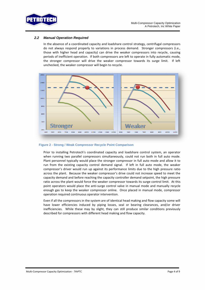
In the absence of a coordinated capacity and loadshare control strategy, centrifugal compressors do not always respond properly to variations in process demand. Stronger compressors (i.e., those with higher head and capacity) can drive the weaker compressors into recycle, causing periods of inefficient operation. If both compressors are left to operate in fully automatic mode, the stronger compressor will drive the weaker compressor towards its surge limit. If left unchecked, the weaker compressor will begin to recycle.
Figure 2 - Strong / Weak Compressor Recycle Point Comparison
Prior to installing Petrotech’s coordinated capacity and loadshare control system, an operator when running two parallel compressors simultaneously, could not run both in full auto mode. Plant personnel typically would place the stronger compressor in full auto mode and allow it to run from the existing capacity control demand signal. If left in full auto mode, the weaker compressor’s driver would run up against its performance limits due to the high pressure ratio across the plant. Because the weaker compressor’s drive could not increase speed to meet the capacity demand and before reaching the capacity controller demand setpoint, the high pressure ratio across the plant would force the weaker compressor towards its surge control limit. At this point operators would place the anti-surge control valve in manual mode and manually recycle enough gas to keep the weaker compressor online. Once placed in manual mode, compressor operation required continuous operator intervention.
Even if all the compressors in the system are of identical head making and flow capacity some will have lower efficiencies induced by piping losses, seal or bearing clearances, and/or driver inefficiencies. While these may by slight, they can still produce similar conditions previously described for compressors with different head making and flow capacity.

Multi-Compressor Capacity Optimization
A Petrotech, Inc White Paper
Multi-Compressor Capacity Optimization - 7thPTC Page 5 of 9
3.0 CAPACITY CONTROLS WITHOUT COORDINATED LOADSHARE
The most fundamental capacity control strategy is to shutdown or start up compressors to match the process throughput requirements. Whenever the process throughput exceeds the operating compressor capacities, additional compressors are placed online. Conversely, whenever the process throughput is less than the minimum flow requirements to prevent compressor surge, compressors are shutdown. More sophisticated capacity controllers reduce or increase the compressor throughput to meet system capacity demands. However, they lack the coordinated loadshare control strategies that enable optimized operation and unnecessary recycling.
Many compressor systems already have capacity control systems installed. These systems provide a capacity demand signal to the operational compressors. However, they lack the coordinated loadshare control element necessary to prevent recycling and other undesirable system interactions resulting from recycling. These capacity control systems do not provide strategies for bringing units online against other online units and they do not provide strategies for dealing with manual operations of system components such as station recycle valves or speed controllers necessary for maintenance tasks.
4.0 IMPLEMENTATION OF COORDINATED CAPACITY AND LOADSHARE CONTROL
When the capacity demand is somewhere between the compressor system minimum throughput and compressor system maximum throughput, a coordinated capacity and loadshare control strategy regulates the compressor speeds, guide vane positions, and system recycle valves to match the throughput to the process demand. A coordinated capacity and loadshare control system must handle off-design operations such as manual modes on speed controllers and valve controllers. System operators often use manual mode features for maintenance and testing purposes. An improperly designed capacity control system will not protect the compressor or the process from undesirable transients while a device is in manual mode or during the manual to automatic transition when the device is returned to automatic mode.
Petrotech’s coordinated capacity and loadshare control system prevents these scenarios by utilizing feedback signals from the individual compressors. Feedback enables the capacity and loadshare controllers to monitor and track manual mode operations and system transients to prevent controllers from reset windup. The capacity and loadshare control system also utilizes offline to online startup initialization and output ramping to minimize undesirable system transients during mode transitions. Contingency strategies are also used to accommodate communications or signal failures. The capacity and loadshare control system coordinates the throughput of the individual compressors to match the capacity demand of a varying process. As a priority, the loadshare controllers equalize each compressor’s operating point relative to its proximity to surge. Equalization of surge margins achieves the maximum operating efficiency for all load sharing units because the units will recycle simultaneously. Once the units begin recycling in response to reduced capacity demand, the operators can take a compressor offline and the remaining online units will adjust their capacities to meet the process demand.
The loadshare controller works to operate each compressor, regardless of its capacity, at equal surge margins. Equal surge margin operation insures that as system demand decreases, each compressor in the system will reduce its capacity down to a pre-defined minimum just prior to the point where the anti-surge controller will begin to actuate the anti-surge control valve. Equal surge margin operation also insures that recycling, when it occurs, will regulate the individual compressor capacities in a way that prevents one unit from recycling while the remaining units are operating well out on their

Multi-Compressor Capacity Optimization
A Petrotech, Inc White Paper
Multi-Compressor Capacity Optimization - 7thPTC Page 6 of 9
respective performance maps. Equal surge margin operation also insures that compressors of differing relative capacity can operate in a parallel configuration without manual operator intervention due to varying process gas conditions and compressor degradation or other system induced losses.
The Petrotech capacity and loadshare control system provides a coordinated approach for multi-compressor systems. The capacity controller consists of the primary capacity controllers. The capacity controllers determine the overall system capacity demand. The loadshare controllers balance the capacity of each operational compressor in response to the overall system capacity demand.
4.1 Capacity Control Elements
Suction Pressure Controller (P1C)
The P1C limits capacity demand on decreasing suction pressure.
Discharge Pressure Controller (P2C)
The P2C limits capacity demand on increasing discharge pressure.
User Assigned Controllers (UAC)
The UAC limits capacity demand on increasing / decreasing user assigned control variable. The UAC controllers have configurable direct/reverse acting features to allow for a variety of control schemes to be deployed. The most common UAC deployments to date are throughput flow and discharge temperature controllers. The current standard deploys a single UAC. In future software releases additional UAC capabilities will be deployed.
Split Range Output Block
The split range output block divides the low selected capacity demand signal into separate high range and low range output signals. The high range output signal provides the capacity demand to the loadshare controllers. The low range output signal provides the capacity demand to the station recycle valve output logic. The low range output signal only begins to modulate the recycle valve position when the loadshare controllers are unable to reduce system capacity any further due to the surge limits or minimum speed limits of the compressors.
Station Recycle Valve Output Block.
The recycle valve output block provides facilities for auto/manual control of the recycle valve. In auto mode, the low range output signal is passed through a ramping routine to prevent any stepping of the valve actuation. In manual mode the valve output can be manipulated directly by an operator.
Feedback Selection Block
The feedback selection block is a very important element of the coordinated capacity and loadshare control system response. The final capacity demand signal passes from the capacity controllers through the split range logic and then to the loadshare controller where it is converted to a surge margin demand setpoint. Ultimately the capacity control feedback signal is proportional to the operating surge margin of the demanded by the loadshare controller. Therefore, the operating surge margin of each compressor is routed back to the feedback selection and unscaled in the inverse manner that the loadshare surge margin demand signal was scaled. This feedback scaling prevents unwanted reset windup of the capacity controllers.
In normal control scenarios where none of the capacity controllers are overriding on their setpoints, but at least one of the capacity controllers is within its operational dead band, the feedback selection logic tempers the capacity control output to prevent the stronger units from running too far ahead of the of the weaker units and driving them toward surge and unnecessary recycling.

Multi-Compressor Capacity Optimization
A Petrotech, Inc White Paper
Multi-Compressor Capacity Optimization - 7thPTC Page 7 of 9
4.2 Loadshare Control Elements
Each loadshare control element described below is replicated for each parallel compressor in the system. The current standard system accommodates up to four parallel compressors per capacity controller. Additional systems can be added if necessary. Refer to Figure 2 for schematic of the capacity and loadshare control system.
Loadshare Controller (LSC)
The loadshare controller is the primary controlling component in the coordinated capacity and loadshare control system. The LSC receives the high range output signal from the split range output block and converts it to a surge margin demand based on the compressor’s turndown range. Each loadshare controller also has a minimum surge margin override to prevent reductions in speed demand when the compressor is near recycle due to operation at the minimum surge margin. The loadshare controller output is routed to the loadshare Controller Output Block.
Power Override Controller (JIC)
Power override controllers are typically deployed on electric motor driven compressors. The power override controller will trim the final output of the loadshare control system if the electric motor drive reaches a preconfigured power limit.
Loadshare Control Output Block
The loadshare control output block selects and properly scales the final loadshare demand signal to be routed to the final speed or guide vane controller. The loadshare control output block also conditions the speed or guide vane feedback signal to prevent controller windup when either the speed controller is in manual mode or when an override controller such as turbine speed or firing temperature is limiting the compressor’s ability to respond to the loadshare demand.
4.3 Capacity and Loadshare Schematic Diagram
The figure below depicts how capacity and loadshare control are deployed in a single Station Master Controller. In this configuration, the all of the program elements are deployed in the master/station logic controller. The unit speed control logic is external to the capacity and loadshare control. Therefore, the output signals are passed via hardwire communication to the unit controller as a speed or guide vane position setpoint. In order to properly manage offline machines and manual mode operations, the unit control systems must provide data such as anti-surge control margin, anti-surge valve position, and speed or guide vane position feedback. This method of deployment is suitable for facilities that already have full unit level sequencing logic systems that do not require or desire integrated control systems retrofits. Petrotech can also provide unit controls as a part of the coordinated capacity and loadshare control deployment.

Multi-Compressor Capacity Optimization
A Petrotech, Inc White Paper
Multi-Compressor Capacity Optimization - 7thPTC Page 8 of 9
Figure 3 - Capacity and Loadshare Control Overview (Only one loadshare controller shown for clarity)
The previous diagram shows the full scope of the coordinated capacity and loadshare control system. An application can be scaled, via configuration parameters, as necessary to exclude any of the capacity controllers or the power override controller.
4.4 Capacity Control Interlock (CCI_Lock)
Capacity Control Interlock prevents unwanted “coupled” reactions between anti-surge controllers and the capacity and loadshare controller. A common CCI_Lock scenario occurs when the compressor anti-surge controller opens the anti-surge control valve. When this happens, the loadshare controller will want to reduce the speed even further to control the surge margin demand. This action will only force the anti-surge controller to further open the anti-surge control valve. If the anti-surge control valve is on a hot recycle loop, the compressor will trip on high gas temperature. In this scenario, CCI_Lock will prevent further reductions of speed by the loadshare controller. The capacity controllers will respond by reducing their signals even further thus transferring control of the process to the station recycle valve output block.
4.5 Methods of Deployment
Petrotech’s capacity and loadshare control system can be deployed in any control system platform supporting IEC 6-1131 structured text. The capacity and loadshare control logic consists of purpose specific functions and function blocks which form the architecture of the capacity and loadshare control system. This architecture allows the programs to be easily ported across IEC 6-1131 compliant platforms with minimal testing and validation. To date the capacity and loadshare control system has been deployed on the Allen Bradley RS Logix system and the GE Fanuc PACS system. Future deployments are slated for Siemens S7 and Honeywell MasterLogic platforms as well. Other control platforms not mentioned will be added as project requirements dictate.

Multi-Compressor Capacity Optimization
A Petrotech, Inc White Paper
Multi-Compressor Capacity Optimization - 7thPTC Page 9 of 9
5.0 SUMMARY OF BUSINESS BENEFITS
5.1 Reduced Energy/Fuel Consumption
Although recycle flow is used to maintain the compressor’s minimum flowrate for the purpose of avoiding surge, recycling is very inefficient in terms of fuel consumption. This is due to the fact that while recycling, the energy consumed to compress the process gas is lost when it is throttled through the recycle valve directly back to the compressor’s suction line. Therefore, the fuel energy consumed to compress the recycled gas is also lost as long as the compressor operates in recycle. An operator, prior to installing Petrotech’s coordinated capacity and loadshare control system, estimated their fuel costs of recycling compressors at approximately 16000 USD/year. Compounded across 5 compressor stations, the total fuel costs incurred due to recycling were approximately 80000 USD/year. A detailed analysis is included in the Appendix of this paper
Additional savings were also realized because the capacity and loadshare control system enabled the operator to operate the weaker compressor further away from surge. In general the performance efficiency of centrifugal compressors are higher at operating points centrally located on the performance map (refer to Figure 4). The fuel cost savings projected from this benefit was approximately 24000 USD/year.
5.2 Reduced Manpower
Because the capacity and loadshare control enables the end-user the ability to operate each compressor in fully automatic mode, plant personnel are free to focus on more high level activities necessary to efficiently operate a facility. Being free of the burden on micro-managing a compressor in manual mode allows plant personnel to focus on routine maintenance tasks. Full automatic control also facilitates the operation on remote unmanned facilities as well.
The operator cited in this document was able to reduce manpower at the facility by an estimated 4000 hours. They also reported they were able to more effectively deploy their labor hours. This opportunity was estimated as an additional 600 hours of labor savings.
5.3 Data Available for Analysis
Petrotech’s coordinated capacity and loadshare control logic is a highly configurable application containing over 70 calibration parameters. Additionally each loadshare control instance (up to four) contains over 40 calibration parameters. The IEC-6-1131 standards the object oriented programming approach employed by Petrotech to developed the capacity and loadshare control system, coupled with the robust configuration capabilities, provides opportunities for the end user to develop their own metrics to further improve the energy efficiency of their processes.

141 James Drive West 7240 Brittmoore, Suite 115 St. Rose, LA 70087 Houston, TX 77041
(504)620-6600 (281)220-3060
Compressor Recycling Calculations - SI Units Version
REV # DATE REV BY DESCRIPTION
0 8 AUG 10 RGM Issued for Review
Reference:C:\Program Files\Mathcad\Mathcad 15\template\Unit Definition File.xmcdz
The Unit Definition File referenced above was created by Petrotech to establish unit naming standards withinMathcad worksheets.
Additional Unit DefinitionsThis worksheet required the addition of the following unit definitions.
Dth 106
BTU Defines a Decatherm
USD 1 Defines a US Dollar ‐ Other currencies can be defined as necessary.
Dthcost 3.25USD
Dth Defines the cost of a Decatherm
filename: Recycle Cost Estimate - SI.xmcd date: 2/14/2012 page 1 of 5

Compressor Recycling Calculations
SI Units Version
Compressor Surge Limit LineCompressor Surge Limit Line (SLL) Data is entered here. This data is used to establish the recycle flowrate.
Qactsll
6796
7352
8981
10194
11304
11859
acmh SLL Flowrate Hdsll
17.73
24.11
31.47
39.85
49.31
54.21
kJ
kg SLL Adiabatic Head
ηascl 0.754 Compressor Adiabatic Efficiency at SCL
ηamax 0.774 Compressor Maximum Adiabatic Efficiency
ηtgt 0.280 Gas Turbine Driver Thermal Efficiency ‐ Estimated value. Dynamicefficiency gain and losses of the drivers were not studied in this analysis.
Process Gas ConditionsThis worksheet section defines/calculates the various process gas conditions
Psgpg 5019.4 kPag Suction Pressure (gauge)
Psapg Psgpg Pstd Suction Pressure (absolute) Psapg 5120.73 kPaa
Tsgpg 21.1 C Suction Temperature (gauge)
Tsapg Tsgpg 273.15 K Suction Temperature (absolute) Tsapg 294.25 K
filename: Recycle Cost Estimate - SI.xmcd date: 2/14/2012 page 2 of 5

Compressor Recycling Calculations
SI Units Version
Process Gas PropertiesThis worksheet section defines/calculates the various process gas properties
MWtpg 17.5kg
kmol Molecular Weight
SGpg
MWtpg
MWtair
Specific GravitySGpg 0.6042
Rgpg
Rgair
SGpg
Specific Gas Constant Rgpg 0.475kJ
kg K
kspg 1.3 Ratio of Specific Heats
σpg
kspg 1
kspg
Isentropic Exponnent σpg 0.2308
Critical Pressure (Pc) and Critical Temperature (Tc) Calculations ‐ Valid only for hydrocarbon gaseswith a Specific Gravity between 0.55 and 1.20. Non‐hydrocarbon gases and gases with specificgravities outside of the defined range require manual entry of Pc and Tc.
Pcpg 4826.8603 kPaa 339.4344 kPaa SGpg Pcpg 4621.8 kPaaCritical Pressure (Pc)
Tcpg 95.1282 K 173.5043 K SGpg Critical Temperature (Tc) Tcpg 200.0 K
filename: Recycle Cost Estimate - SI.xmcd date: 2/14/2012 page 3 of 5

Compressor Recycling Calculations
SI Units Version
The process gas compressibility factor calculations use a Redlich Kwong (RKZ) Compressibility(Zs)calculation. This method provides sufficient accuracy for most process gases and conditions within thescope of this worksheet. Process gases and conditions outside reasonable accuracy ranges for RKZcalculations require manual entry of Zs.
Z 1 Seed value for iteration below
Arkz 0.42748Psapg
Pcpg
Tcpg
Tsapg
2.5
Arkz 0.1803
Brkz 0.08664Psapg
Pcpg
Tcpg
Tsapg
Brkz 0.06523
Given
1
Z Brkz
Arkz
Z Z Brkz 1=
Zspg Find Z( ) Suction Compressibility Zspg 0.8904
Compressor Operating Data at Assumed Recycle PointAssumed Recycle Requirements ‐ Ths analysis is assumes the non‐load shared compressor will operate on
the Surge Control Line (SCL). And the recycle amount will be rcypct 10.00 % of the SLL flowrate (Qactsll)
rcypct 10 % Average Percentage of Flowrate relative to SLL flow while recycling
rcyhr_day 9hr
day Hours per day operating in recycle
rcyday_yr 75day
yr Days per year operating in recycle
rcyhr_year rcyhr_day rcyday_yr Hours per year operating in recycle rcyhr_year 675hr
yr
Hdop 43.9094kJ
kg Operating Head
filename: Recycle Cost Estimate - SI.xmcd date: 2/14/2012 page 4 of 5
Compressor Recycling Calculations
SI Units Version
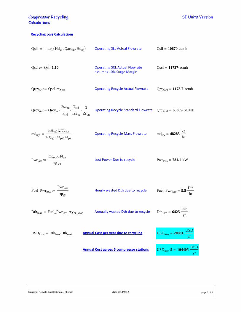
Recycling Loss Calculations
Qsll linterp Hdsll Qactsll Hdop Operating SLL Actual Flowrate Qsll 10670 acmh
Qscl Qsll 1.10 Operating SCL Actual Flowrateassumes 10% Surge Margin
Qscl 11737 acmh
Qrcyact Qscl rcypct Operating Recycle Actual Flowrate Qrcyact 1173.7 acmh
Qrcystd Qrcyact
Psapg
Pstd
Tstd
Tsapg
1
Zspg
Operating Recycle Standard Flowrate Qrcystd 65365 SCMH
mdrcy
Psapg Qrcyact
Rgpg Tsapg Zspg Operating Recycle Mass Flowrate mdrcy 48285
kg
hr
Pwrloss
mdrcy Hdop
ηascl
Lost Power Due to recycle Pwrloss 781.1 kW
Fuel_Pwrloss
Pwrloss
ηtgt
Hourly wasted Dth due to recycle Fuel_Pwrloss 9.5Dth
hr
Dthloss Fuel_Pwrloss rcyhr_year Annually wasted Dth due to recycle Dthloss 6425Dth
yr
USDloss Dthloss Dthcost Annual Cost per year due to recycling USDloss 20881USD
yr
Annual Cost across 5 compressor stations USDloss 5 104405USD
yr
filename: Recycle Cost Estimate - SI.xmcd date: 2/14/2012 page 5 of 5