Embed Size (px)
Citation preview

1
Multi-Carrier Technology for Precision
Personnel Location
Electrical and Computer Engineering DepartmentWorcester Polytechnic Institute
Worcester, Massachusetts
funded by
US Department of Justice
National Institute of Justice

2
The PPL Team
Research Assistants
� Jack Coyne
� Hauke Daempfling
� Jason Farmer
� Jason Huang
� Shashank Kulkarni
� Hemish Parikh
� Ben Woodacre
� Vincent Amendolare
� David Holl
Faculty
� David Cyganski
� R. James Duckworth
� Sergey Makarov
� William Michalson
� John Orr
Technician
� Bob Boisse

3
System Overview
Personnel
Unit
Reference units
Commander
Display
4
Locator Concept Drawing
PIFA Wide
BW
Antenna
Distress
Button
Data Channel
Antenna
Electronics and
Battery
Compartment

5
Basic Concept
�Sharply defined energy pulses are unnecessary
for precise location
� Avoids problems of wide and flat bandwidth
antenna, receiver, and transmitter design
�Multiple continuous carriers that sample frequency
space can be utilized
� Spectrally friendly, near 0 bandwidth
components
�Superresolution techniques can trade SNR for
increased precision at fixed bandwidth
� Also provides means for multipath resolution

6
Multi-Carrier Wideband
�Super-resolution SAR/ISAR Radar
� Enhances Radar resolution to centimeters
�Orthogonal Frequency Division Multiplexing
� A data communications innovation which allows high speed data to be transmitted over low-quality telephone wires (DSL service) or via wireless
Approach based upon two recent innovations:

7
Spectrally Friendly System
�The spectral footprint of the MC-WB signal
can be tailored to avoid existing services
MC-WB
Existing Services

8
System Analysis and Design
�To move from concept to implementation:
� Complete analysis of performance
• Mathematical performance modeling
• System Engineering criteria
• Simulation of end-to-end system
�Prototype Construction/Evaluation
� Troubleshooting/Feedback/Re-analysis
�Development of encompassing technology
� Auto-calibration, data exchange, …
9
Embedded System Design
� Transmitter requirements
� Continuously transmits the OFDM signal
� Must be small, lightweight, and have low power
consumption (battery powered)
� Receiver requirements
� Self configuring
� Continuously receives transmitter signals to
determine position in 3-dimension
� Complex signal processing
� Approach: FPGA based Software Radio Architecture

10
First Generation Receiver RF Chain
A/D
FPGA (PC
interface)
Antenna
Mixer

11
Second Generation RF and digital Receiver Boards
Digital Controller
board
Analog to Digital
board
RF Front End
board

12
Antenna Design
PIFA (Planar Inverted
Foam Antenna)
reduced size, wide
bandwidth patch
antenna and control
board
13
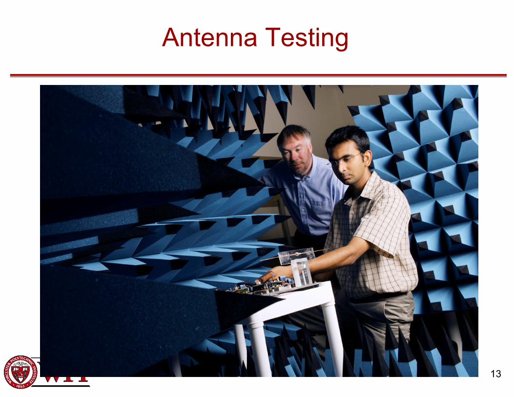
Antenna Testing

14
Rapid Concept Evaluation
•We often used off-the-shelf components and tested low
bandwidth scale model systems first.
•Outdoor shake-downs were very common.

15
Super-res Multi-path TOA observations
The laboratory tests
shown here demonstrate
separability of multipath
signals inside a room
Here each “bounce” is
resolved from the others
What is the practical
resolvability of multi-path
signals?
16
0
5
10
15
20
25
30
-10 0 10 20 30 40 50 60 70
SNR, dB
Path Length Difference, m
1 Mhz
2 Mhz
4 MHz
8 MHz
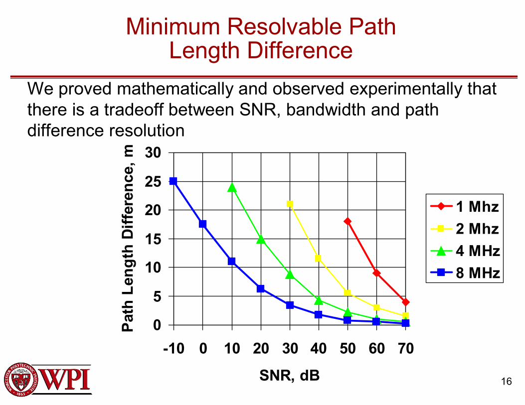
Minimum Resolvable PathLength Difference
We proved mathematically and observed experimentally that
there is a tradeoff between SNR, bandwidth and path
difference resolution

17
Forensic Test Analysis
Laboratory tests reveal new
and important phenomena
that must be understood for
further improvement of PPL
performance.
Electromagnetic simulations
are applied to gain this
understanding through
forensic analysis of test
results.
18
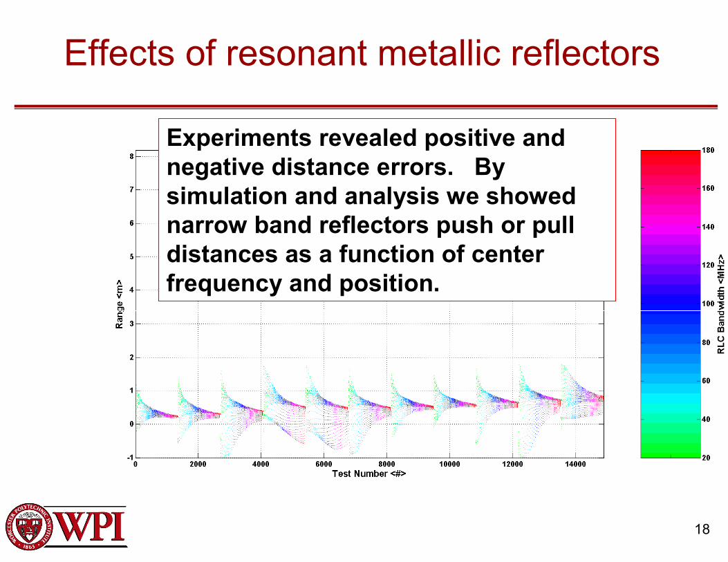
Effects of resonant metallic reflectors
Experiments revealed positive and
negative distance errors. By
simulation and analysis we showed
narrow band reflectors push or pull
distances as a function of center
frequency and position.

19
Outdoor 2D TDOA results (free roving transmitter -30dBm tx power)
Geometry Effects
Receivers
Multipath Errors

20
Indoor Testing

21
Indoor Environment
Metal ceiling and floor decks
Steel building structure
22
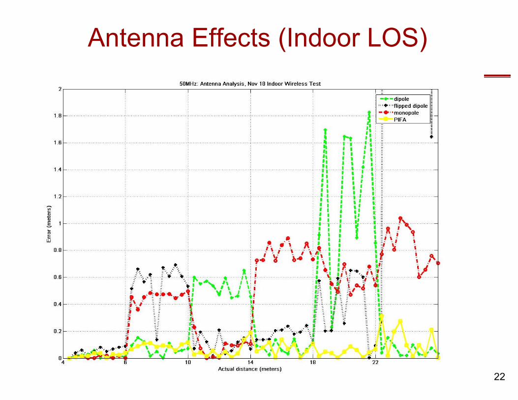
Antenna Effects (Indoor LOS)
23
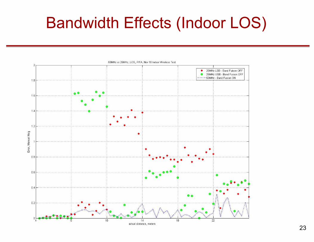
Bandwidth Effects (Indoor LOS)
25
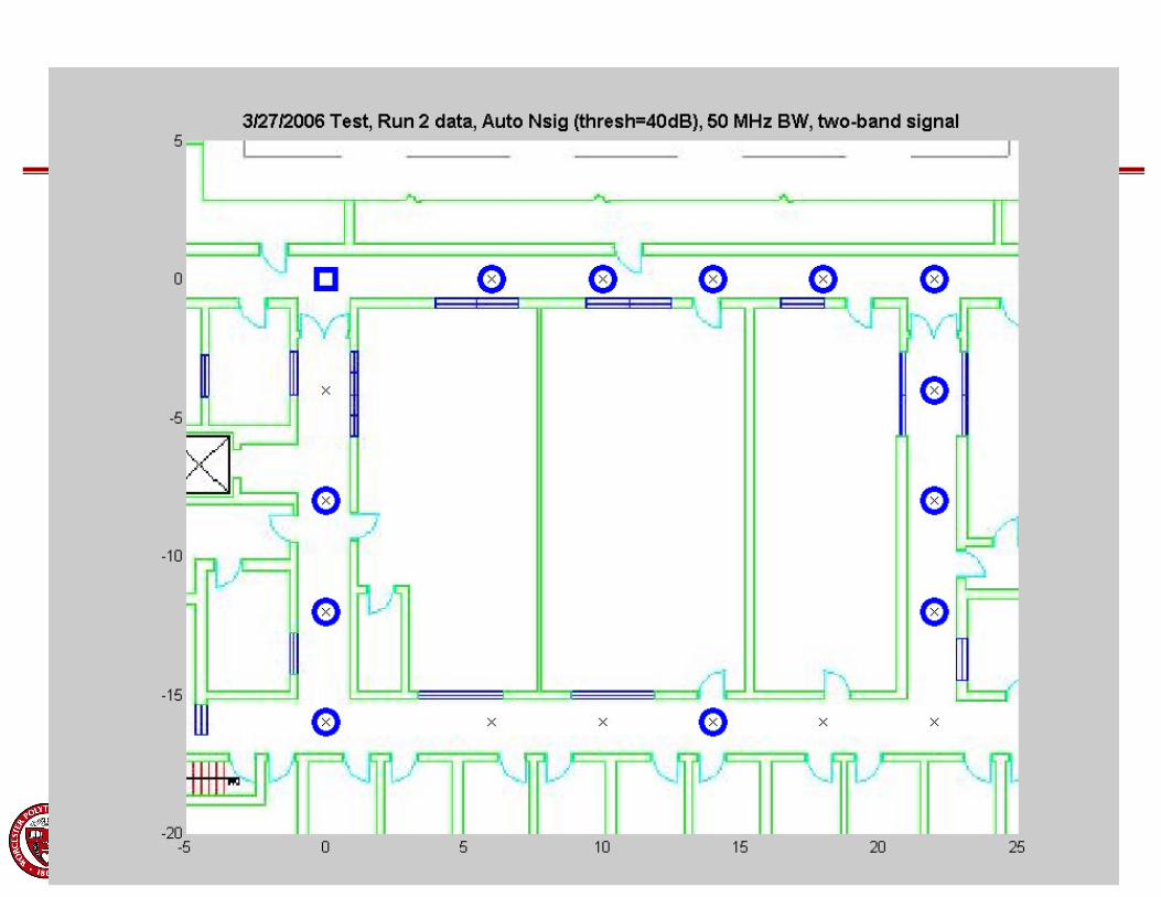
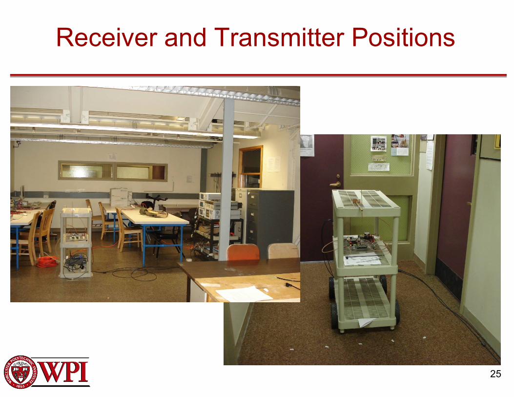
Receiver and Transmitter Positions

Positions 8-15 are NLOS
4 our of 8 NLOS result in direct path solutions

TOA Range Solution Arcs
Target Location
26 by 16
meter area of
Atwater Kent
3rd Floor

28
Using NLOS information only
Target Location
29
MCWB/Superres/TDOA: The Problem
� Solving TDOA problem requires pre-selection and
grouping of “good” direct path solutions without
“first arrival information”
� Once this selection is made, multi-lateralization
must be performed
� Unfortunately, errors are already captured in
each single TDOA sub-result
� There are too many permutations of sensors
and multiple solutions to consider….
� There was much gnashing of teeth…. A new
approach was needed

30
� Center of red
region denotes
highest
certainty
solution
� 26 by 16 meter
area of Atwater
Kent 3rd Floor
New WPI Algorithm: All NLOS data
31
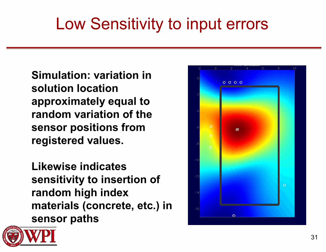
Low Sensitivity to input errors
Simulation: variation in
solution location
approximately equal to
random variation of the
sensor positions from
registered values.
Likewise indicates
sensitivity to insertion of
random high index
materials (concrete, etc.) in
sensor paths

32
Kaven Hall Demo
Antennas on
3 sides of
area
Antennas
facing
directly into
masonary
No training
information
or pre-sited
devices

33
Kaven Hall Geo-lab test site
Demo site is
the Civil Eng.
Dept.
Geology Lab
Steel Frame
and concrete
block
construction
with heavy
equipment
and metal
furnishings

34
The command post
Real-Time-
update
display of
location
solution
and signal
integrity
on
command
console

35
Command Console
� 2D position
and signal
integrity
display from
Kaven Hall
demo
� White
square
indicates
true position

36
Conclusions
�Real-time computation and display of 2-D location from through-wall signals has been demonstrated with a only a 30 MHz multi-carrier signal
� 3-D location will soon be tested
�We await granting of experimental access of additional bandwidth by the FCC to pursue evaluation in increasingly difficult environments
�Approaching commercialization stage


![world.toagroup.com...the natural world and is very effective in creating a country style. TOA Prairie TOA TOA TOA 851B TOA C] TOA 12 04 Make you feel like adventures in Africa. with](https://img.dokumen.tips/doc/110x75/5f0a99557e708231d42c6c3c/world-the-natural-world-and-is-very-effective-in-creating-a-country-style.jpg)