Embed Size (px)
Citation preview

General rights Copyright and moral rights for the publications made accessible in the public portal are retained by the authors and/or other copyright owners and it is a condition of accessing publications that users recognise and abide by the legal requirements associated with these rights.
Users may download and print one copy of any publication from the public portal for the purpose of private study or research.
You may not further distribute the material or use it for any profit-making activity or commercial gain
You may freely distribute the URL identifying the publication in the public portal If you believe that this document breaches copyright please contact us providing details, and we will remove access to the work immediately and investigate your claim.
Downloaded from orbit.dtu.dk on: Oct 24, 2021
Multi-Agent Sliding Mode Control for State of Charge Balancing Between BatteryEnergy Storage Systems Distributed in a DC Microgrid
Morstyn, Thomas; Savkin, Andrey V.; Hredzak, Branislav; Agelidis, Vassilios G.
Published in:I E E E Transactions on Smart Grid
Link to article, DOI:10.1109/TSG.2017.2668767
Publication date:2018
Document VersionPeer reviewed version
Link back to DTU Orbit
Citation (APA):Morstyn, T., Savkin, A. V., Hredzak, B., & Agelidis, V. G. (2018). Multi-Agent Sliding Mode Control for State ofCharge Balancing Between Battery Energy Storage Systems Distributed in a DC Microgrid. I E E E Transactionson Smart Grid, 9(5), 4735-4743. https://doi.org/10.1109/TSG.2017.2668767
1
Multi-Agent Sliding Mode Control for
State of Charge Balancing Between Battery Energy
Storage Systems Distributed in a DC MicrogridThomas Morstyn, Member, IEEE, Andrey V. Savkin, Senior Member, IEEE,
Branislav Hredzak, Senior Member, IEEE and Vassilios G. Agelidis, Fellow, IEEE
Abstract—This paper proposes the novel use of multi-agent
sliding mode control for state of charge balancing between
distributed DC microgrid battery energy storage systems. Unlike
existing control strategies based on linear multi-agent consensus
protocols, the proposed nonlinear state of charge balancing
strategy (i) ensures the battery energy storage systems are
either all charging or all discharging, thus eliminating circulating
currents, increasing efficiency and reducing battery lifetime
degradation, (ii) achieves faster state of charge balancing, (iii)
avoids overloading the battery energy storage systems during
periods of high load and (iv) provides plug and play capability.
The proposed control strategy can be readily integrated with
existing multi-agent controllers for secondary voltage regulation
and accurate current sharing. The performance of the proposed
control strategy was verified with an RTDS Technologies real-
time digital simulator, using switching converter models and
nonlinear lead-acid battery models.
Index Terms—Battery energy storage systems, DC microgrid,
distributed energy storage, distributed sliding mode control,
hybrid systems, multi-agent control, secondary control, state of
charge balancing.
I. INTRODUCTION
THE rapid adoption of distributed renewable sources is
being driven by the potential for increased efficiency,
increased reliability and reduced pollution compared to the tra-
ditional model of centralised power generation [1]. However,
the intermittent nature of these sources introduces challenges
for network power quality and stability. At the same time,
technological developments and increased scales of production
have driven down the price of battery energy storage technolo-
gies, making them viable for power network applications [2].
Microgrids have been proposed for organising future power
networks made up of distributed renewable sources and en-
ergy storage systems [3]. A microgrid is a collocated set of
generation sources, energy storage systems and loads that are
able to operate autonomously [4]. In particular, DC microgrids
have the advantage of requiring fewer power conversion stages
when integrating modern DC-based sources (e.g. Photovolatic
T. Morstyn is the with the Department of Engineering Science atthe University of Oxford, Oxford OX1 3PJ, United Kingdom. (email:[email protected])
A. V. Savkin and B. Hredzak are with the School of Electrical Engineeringand Telecommunications at The University of New South Wales (UNSWAustralia), Sydney, NSW 2052 Australia. (email: [email protected],[email protected]).
V. G. Agelidis is with the Department of Electrical Engineering at theTechnical University of Denmark (DTU), 4000 Roskilde, Denmark. (email:[email protected]).
(PV), variable speed wind, batteries), increasing efficiency [5].
Also, DC microgrids have been shown to provide reliability
an order of magnitude higher than AC microgrids [6].
To achieve autonomous operation, a primary load sharing
control strategy is required between microgrid sources. Decen-
tralised V-I droop control is the standard primary control strat-
egy used in DC microgrids [7]. However, V-I droop control
has several limitations when used to coordinate load sharing
between battery energy storage systems (BESSs). Voltage
drops across the microgrid lines will cause each battery to
operate at a different charging/discharging current. This will
cause the state of charge (SoC) levels of the BESSs to diverge.
This is undesirable, since BESSs that have run out of charge
cannot contribute their current capacities to the microgrid.
Also, batteries suffer significant lifetime deterioration when
overcharged or undercharged [8].
SoC balancing has been proposed as a means of fully
utilising the combined power and energy capacities of dis-
tributed microgrid BESSs [9]. Under a SoC balancing control
strategy, the BESSs share the microgrid load, while using
their excess current capacities to move towards a balanced
SoC. Once a balanced SoC is achieved, the combined current
capacity of the BESSs is available to balance the microgrid
load. None of the BESSs prematurely run out of energy. Also,
the maximum depth of discharge reached by the BESSs is
reduced, improving lifetime and efficiency.
A centralised control strategy can be used to provide SoC
balancing between microgrid BESSs [10], [11]. However, a
central controller introduces a single point of failure, and the
communications and processing infrastructure for centralised
SoC estimation and control may be impractical for microgrids
with many small distributed BESSs [12]. Also, data centrali-
sation introduces privacy and security concerns [13].
Multi-agent control provides a scalable means of organis-
ing cooperation between microgrid BESSs, without requiring
a central controller. Under a multi-agent control strategy,
autonomous agents use local information and neighbour-to-
neighbour communication to cooperatively achieve common
objectives [14].
Multi-agent control strategies have been proposed for a
range of microgrid applications, including secondary control
[15]–[17] and economic dispatch [18]–[20]. In [21], a control
strategy is presented to coordinate the operating modes of
renewable sources and BESSs in an islanded DC microgrid.
When the batteries approach full charge, renewable sources use
2
Time (h)
0 0.2 0.4 0.6 0.8 1
Pow
er
(kW
)
-2
-1
0
1
2Batt. 1
Batt. 2Batt. 1 Overloaded
Batt. 2 Charged
(a) Battery output powers.
Time (h)
0 0.2 0.4 0.6 0.8 1
Sta
te o
f C
harg
e (
%)
20
40
60
80
100Batt. 1
Batt. 2
(b) Battery SoC levels.
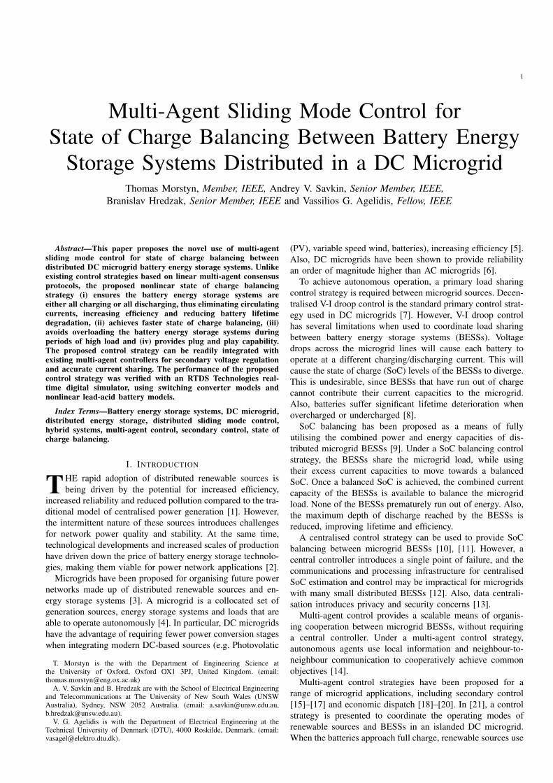
Fig. 1. Microgrid with two 2kWh, 1kW rated BESSs operating under a linear SoC balancing strategy with high gain. Initially BESS 1 is overloaded. Also,BESS 2 is charged, resulting in circulating currents.
Time (h)
0 0.2 0.4 0.6 0.8 1
Pow
er
(kW
)
-2
-1
0
1
2Batt. 1
Batt. 2
(a) Battery output powers.
Time (h)
0 0.2 0.4 0.6 0.8 1
Sta
te o
f C
harg
e (
%)
20
40
60
80
100Batt. 1
Batt. 2
(b) Battery SoC levels.
Fig. 2. Microgrid with two 2kWh, 1kW rated BESSs operating under a linear SoC balancing strategy, with the maximum gain possible without overloadingbattery 1. Since only a fraction of the battery power capacity is used for most of the operating time, SoC balancing is very slow.
Time (h)
0 0.2 0.4 0.6 0.8 1
Pow
er
(kW
)
-2
0
2Batt. 1
Batt. 2
(a) Battery output powers.
Time (h)
0 0.2 0.4 0.6 0.8 1
Sta
te o
f C
harg
e (
%)
20
40
60
80
100Batt. 1Batt. 2
(b) Battery SoC levels.
Fig. 3. Microgrid with two 2kWh, 1kW rated BESSs operating under the proposed desirable nonlinear SoC balancing strategy.
curtailment to regulate the microgrid voltage. Communication
between the BESSs is provided by a power line signalling
method, which entails all-to-all (rather than neighbour-to-
neighbour) communication. A review of DC microgrid con-
trol strategies, including distributed multi-agent approaches,
is presented in [22]. The rigorous mathematical analysis of
multi-agent control strategies is identified as a key research
challenge.
Multi-agent SoC balancing control strategies for distributed
microgrid BESSs are presented in [9], [23]–[28]. For DC
microgrids, multi-agent SoC balancing has been combined
with multi-agent secondary voltage control [23] and extended
to coordinate heterogeneous energy storage technologies [24].
Existing multi-agent SoC balancing strategies [9], [23]–[28]
use linear consensus protocols. This introduces an undesirable
trade-off between the rate of SoC balancing and the utilisation
of the BESS current capacities. To demonstrate the limitations
of a linear consensus strategy, consider the idealised example
of a microgrid with two 2kWh, 1kW rated BESSs and a 1kW
load. Fig. 1(a) and Fig. 1(b) show the battery output powers
and SoC levels, under a linear consensus strategy with high
gain. Initially, BESS 1 is overloaded and BESS 2 operates in
charging mode. The circulating currents between the BESSs
will result in lower efficiency, and lifetime degradation due to
unnecessary cycling of the batteries. Fig. 2(a) and Fig. 2(b)
show the battery output powers and SoC levels when the gain
is reduced to ensure the BESSs are not overloaded. In this
case, the rate of SoC balancing is very slow since the full
power capacities of the batteries are not utilised.
The desirable operation shown in Fig. 3(a) and Fig. 3(b)
requires a nonlinear control strategy. BESS 1 operates at its
maximum output power to supply the full microgrid load until
a balanced SoC is reached. During this time, BESS 2 operates
at zero output power, so there are no circulating currents. This
paper proposes a nonlinear control strategy that achieves this
desired operation.
This paper proposes the novel use of multi-agent sliding
mode control for SoC balancing between distributed DC
microgrid BESSs. The proposed multi-agent sliding mode con-
trol strategy provides qualitative improvements over existing
SoC balancing strategies based on linear consensus protocols,
namely:
(i) No Circulating Currents: The microgrid batteries are
either all charging, or all discharging, depending on the
net microgrid load. This prevents circulating currents
and unnecessary charge/discharge cycles, improving ef-
ficiency and battery lifetime.
(ii) Fast SoC Balancing: During periods of low load, BESSs
with low SoC do not participate in the droop control.
This provides fast SoC balancing without introducing
circulating currents.
(iii) No Overload: During periods of high load, all of the
BESSs share the microgrid load within their current ca-
pacities, so that none are overloaded. The BESSs continue

3
PV
Batt. 4
20Ω
30Ω
20Ω
30Ω30Ω
Batt. 3
Batt. 2
Batt. 130μH 0.1Ω 30μH 0.1Ω 30μH 0.05Ω
30μH 0.05Ω
30μH 0.05Ω30μH 0.05Ω 30μH 0.1Ω
30μH
0.1Ω
30μH
0.1Ω
s4,vo4,iL4pu s3,vo3,iL3
s3,vo3,iL3
s2,vo2,iL2
s2,vo2,iL2
s1,vo1,iL1
pu
pu
pu
pu
pu
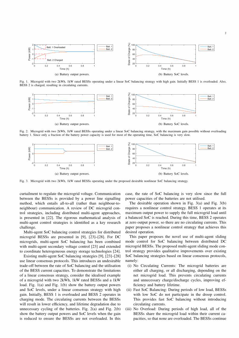
Fig. 4. Islanded 100V DC microgrid, with four lead-acid BESSs, five resistiveloads and a PV generation source, connected together by RL lines. The BESSsare connected by a sparse communication network, allowing neighbour-to-neighbour communication.
to move towards a balanced SoC at a reduced rate.
(iv) Plug and Play: The distributed sliding mode controllers
used for SoC balancing do not need system parameter in-
formation, and do not need information on the number of
BESSs. This provides plug and play capability, i.e. proper
operation is maintained when BESSs connect/disconnect
from the communication network and microgrid.
The SoC balancing control is integrated with existing multi-
agent secondary control strategies for secondary voltage reg-
ulation and accurate current sharing. Once a battery’s SoC
reaches a boundary layer around the average of its neighbours’
SoC levels, its nonlinear sliding mode controller swaps to a
linear interpolation that prevents chattering. The performance
of the proposed control strategy was verified with an RTDS
Technologies real-time digital simulator for a DC microgrid
with PV generation and lead-acid BESSs, using switching
converter models and nonlinear lead-acid battery models.
The rest of this paper is organised as follows. Section II
presents the proposed multi-agent sliding mode control strat-
egy. Section III provides real-time digital simulation results
verifying the performance of the proposed control strategy.
Section IV concludes the paper. In the appendix, the conditions
for SoC synchronisation between BESSs operating under the
proposed control strategy are rigorously analysed.
II. PRINCIPLE OF OPERATION
This study considers a DC microgrid with distributed BESSs
V = {1, . . . , N}, each consisting of a battery connected to
the microgrid through a controllable bidirectional DC–DC
converter. The BESSs are connected by a sparse communi-
cation network allowing bidirectional neighbour-to-neighbour
communication between them. In particular, Fig. 4 shows the
islanded DC microgrid considered in this study, which has
a PV generation source and four BESSs. Fig. 5 shows the
topology of the individual BESSs.
On the primary control level, the standard V-I droop control
is used for decentralised load sharing to maintain the microgrid
power balance. A secondary control level is introduced to
regulate the average BESS output voltage to the nominal
Li Ci
Batteryvoi
iLi
pbatti
vbatti
pi
ioi
Fig. 5. BESS consisting of a battery and bidirectional DC–DC boost converter.
vmg
rdiioivoi
PI
Droop ControlSecondary
Voltage ControlDistributed
Avg. Consensus
voi∫
From Neighbours
v'mgi
Sliding Mode
Control
voi
si
∫ PI
ui=1
ui<1
Secondary Current Control
1|Ni|
sj∑∈j Ni
1|Ni| ∈j Ni
∑
iLj1|Ni| ∈j Ni
∑
voj av
aipu iLi
pu
iLipu ui ]1,0[∈
iLipu
iLipu
*
Fig. 6. Block diagram of the proposed control strategy for one of theBESSs. The proposed control strategy includes a distributed sliding modecontroller for SoC balancing, added to distributed secondary voltage andcurrent controllers. V-I droop control generates the voltage reference for thelower level voltage/current controllers.
microgrid voltage on a slower time-scale, while providing
accurate current sharing between the BESSs. In particular,
the multi-agent implementation of the secondary control level
from [17] is used. This paper proposes a modification to the
multi-agent secondary control level, with distributed sliding
mode controllers introduced to provide SoC balancing between
the BESSs.
Fig. 6 shows a block diagram of the proposed control
strategy for one of the BESSs.
A. Decentralised Primary Control
Decentralised load sharing between the BESSs is provided
by the standard V-I droop control,
v∗oi(t) = v′mgi(t)− rdiioi(t). (1)
v∗oi is the BESS output voltage reference, ioi is the output
current and rdi is the droop coefficient. v′mgi is a modified
version of the nominal microgrid voltage vmg. v′mgi is set
by the multi-agent secondary level control strategy to achieve
secondary voltage control and SoC balancing between the
BESSs.
The output voltage reference v∗oi is sent to the lower level
cascaded voltage and current controllers from [29], which
generate the duty cycle for pulse width modulation of the
bidirectional DC–DC converter switches.

4
The decentralised droop control only provides approximate
current sharing between the BESSs, and will introduce steady
state voltage offsets. Although voltage differences between the
BESSs are inevitable due to line resistances, the voltage levels
should vary around the nominal microgrid voltage.
This motivates the introduction of a DC microgrid sec-
ondary control level. On a slower time-scale than the primary
control, the secondary control level strategy restores the av-
erage voltage to the nominal microgrid voltage and modifies
the BESSs output currents for accurate current sharing, by
adjusting the modified nominal microgrid voltage v′mgi. This
is described in detail in Section II-B. Section II-C describes the
proposed multi-agent sliding mode control strategy, which is
added to the secondary control level to provide SoC balancing
between the BESSs.
B. Multi-Agent Secondary Control for Average Voltage Regu-
lation and Accurate Current Sharing
In this study, the proposed multi-agent sliding mode control
strategy for SoC balancing between the BESSs is integrated
with the multi-agent secondary control strategy from [17], for
accurate current sharing and voltage restoration.
Let the communication network between the BESSs be
represented by a connected undirected graph G(V, E). E is
the set of graph edges, where the unordered pair {i, j} ∈ E if
there is a communication link between BESSs i and j. Let Ni
be the neighbour set of BESS i, where j ∈ Ni if {i, j} ∈ E .
Each BESS implements the distributed dynamic average
consensus protocol from [30], using local information and
information from their neighbours to update a local estimate
of the average output voltage voi,
voi(t) = voi(t) +av|Ni|
∫ t
0
∑
j∈Ni
(
voj(τ)− voi(τ))
dτ. (2)
|Ni| is the number of neighbours of BESS i and av is
the average voltage consensus gain. Under this protocol, for
step changes in the BESS output voltages, limt→∞(voi −1N
∑N
j=1 voj) = 0, ∀i ∈ V .
The BESSs also keep estimates of the average per-unit
battery current of the BESSs that are fully participating in the
droop control ipuLi . To achieve SoC balancing, the local sliding
mode controller generates a control signal ui ∈ [0, 1] which
sets the BESS’s level of participation in the droop control (the
mechanism for this is described in detail in Section II-C). Full
participation is given by ui = 1. The dynamic average current
consensus protocol is designed so that BESSs which are not
fully participating in the droop control (ui < 1) pass through
the average of their neighbours’ estimates, rather than using
their own battery current as an input.
The distributed dynamic average current consensus protocol
is given by,
ipuLi(t) = zi(t) +ai|Ni|
∫ t
0
∑
j∈Ni
(
ipuLj(τ)− ipuLi(τ))
dτ,
zi(t) =
{
ipuLi(t), ui(t) = 1,1
|Ni|
∑
j∈NiipuLj(t), ui(t) < 1.
(3)
ai is the average current consensus gain. The per-unit battery
current ipuLi = iLi/Cbatti (i.e. the battery current divided
by the charge capacity) is used, to account for BESSs with
different charge capacities. Let the set of BESSs that are
fully participating in the droop control be given by P ={i ∈ V|ui = 1}. For step changes in the battery currents,
limt→∞(ipuLi −1
|P|
∑
j∈P ipuLj) = 0, ∀i ∈ V .
The nominal microgrid voltage used by the droop control
v′mgi is modified by PI controllers for secondary voltage and
current control.
v′mgi(t) = vmg + kvpevi (t) + kipe
ii(t) +
∫ t
0
kvi evi (τ) + kiie
ii(τ) dτ,
evi (t) = vmg − voi(t), eii(t) = ui(t)ipuLi(t)− ipuLi(t). (4)
kvp and kvi are the secondary voltage control proportional and
integral gains. kip and kii are the secondary current control
proportional and integral gains.
Under the secondary control strategy (4), v′mgi is increased
if the local estimate of the average BESS output voltage voi is
below the nominal microgrid voltage vmg, and decreased if voiis above vmg. This regulates the average of the BESS output
voltages 1N
∑N
i=1 voi to the nominal microgrid voltage vmg
[17]. v′mgi is also adjusted for secondary current control. When
a BESS is fully participating in the droop control (ui = 1), its
per-unit battery current ipuLi is regulated to the local estimate
of the average per-unit current of the participating batteries
ipuLi . When a BESS is not participating in the droop control
(ui = 0), its battery current is regulated to zero.
C. Multi-Agent Sliding Mode Control for State of Charge
Balancing
The BESS’s local sliding mode controller generates a con-
trol signal ui that determines its level of participation in the
droop control to achieve SoC balancing, based on the local
SoC si, and the average SoC of its neighbours. The average
SoC of the neighbours of BESS i at time t is defined as
Ai(t) :=1
|Ni|
∑
j∈Ni
sj(t). (5)
First, the following (idealised) sliding mode control function
is proposed,
ui(t) =
1, si(t) ≥ Ai(t) and ipuLi(t) > 0,
1, si(t) ≤ Ai(t) and ipuLi(t) < 0,
0, otherwise.
(6)
The BESS will fully participate in the droop control (ui = 1)
if, (a) the microgrid has a net load (ipuLi > 0) and the local
SoC is greater than, or equal to, the average of the neighbours’
SoC levels, or (b) the microgrid has net generation (ipuLi < 0)
and the local SoC is less than, or equal to, the average of the
neighbours’ SoC levels.
The key idea behind the design of the sliding mode control
function is that the BESSs always move closer to the average
SoC of their neighbours, or keep the same SoC. The appendix
provides a rigorous analysis of the conditions under which the
proposed multi-agent sliding mode control strategy provides
SoC synchronisation.
5
0.996 0.998 1.000 1.002 1.004
si/Ai
-1.0
-0.5
0.0
0.5
1.0
ipu
Li/ip
um
ax
L
0.0
0.2
0.4
0.6
0.8
1.0
ui
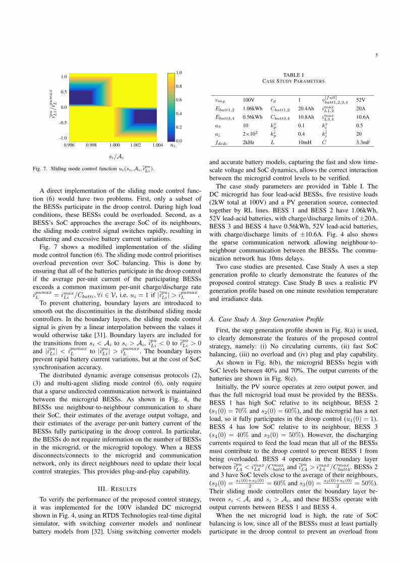
Fig. 7. Sliding mode control function ui(si,Ai, ipuLi
).
A direct implementation of the sliding mode control func-
tion (6) would have two problems. First, only a subset of
the BESSs participate in the droop control. During high load
conditions, these BESSs could be overloaded. Second, as a
BESS’s SoC approaches the average SoC of its neighbours,
the sliding mode control signal switches rapidly, resulting in
chattering and excessive battery current variations.
Fig. 7 shows a modified implementation of the sliding
mode control function (6). The sliding mode control prioritises
overload prevention over SoC balancing. This is done by
ensuring that all of the batteries participate in the droop control
if the average per-unit current of the participating BESSs
exceeds a common maximum per-unit charge/discharge rate
ipumaxL = imax
Li /Cbatti, ∀i ∈ V , i.e. ui = 1 if |ipuLi | > ipumaxL .
To prevent chattering, boundary layers are introduced to
smooth out the discontinuities in the distributed sliding mode
controllers. In the boundary layers, the sliding mode control
signal is given by a linear interpolation between the values it
would otherwise take [31]. Boundary layers are included for
the transitions from si < Ai to si > Ai, ipuLi < 0 to ipuLi > 0
and |ipuLi | < ipumaxL to |ipuLi | > ipumax
L . The boundary layers
prevent rapid battery current variations, but at the cost of SoC
synchronisation accuracy.
The distributed dynamic average consensus protocols (2),
(3) and multi-agent sliding mode control (6), only require
that a sparse undirected communication network is maintained
between the microgrid BESSs. As shown in Fig. 4, the
BESSs use neighbour-to-neighbour communication to share
their SoC, their estimates of the average output voltage, and
their estimates of the average per-unit battery current of the
BESSs fully participating in the droop control. In particular,
the BESSs do not require information on the number of BESSs
in the microgrid, or the microgrid topology. When a BESS
disconnects/connects to the microgrid and communication
network, only its direct neighbours need to update their local
control strategies. This provides plug-and-play capability.
III. RESULTS
To verify the performance of the proposed control strategy,
it was implemented for the 100V islanded DC microgrid
shown in Fig. 4, using an RTDS Technologies real-time digital
simulator, with switching converter models and nonlinear
battery models from [32]. Using switching converter models
TABLE ICASE STUDY PARAMETERS
vmg 100V rd 1 v[full]batt1,2,3,4 52V
Ebatt1,2 1.06kWh Cbatt1,2 20.4Ah imaxL1,2 20A
Ebatt3,4 0.56kWh Cbatt3,4 10.8Ah imaxL3,4 10.6A
av 10 kvp 0.1 kvi 0.5
ai 2×10² kip 0.4 kii 20
fdcdc 2kHz L 10mH C 3.3mF
and accurate battery models, capturing the fast and slow time-
scale voltage and SoC dynamics, allows the correct interaction
between the microgrid control levels to be verified.
The case study parameters are provided in Table I. The
DC microgrid has four lead-acid BESSs, five resistive loads
(2kW total at 100V) and a PV generation source, connected
together by RL lines. BESS 1 and BESS 2 have 1.06kWh,
52V lead-acid batteries, with charge/discharge limits of ±20A.
BESS 3 and BESS 4 have 0.56kWh, 52V lead-acid batteries,
with charge/discharge limits of ±10.6A. Fig. 4 also shows
the sparse communication network allowing neighbour-to-
neighbour communication between the BESSs. The commu-
nication network has 10ms delays.
Two case studies are presented. Case Study A uses a step
generation profile to clearly demonstrate the features of the
proposed control strategy. Case Study B uses a realistic PV
generation profile based on one minute resolution temperature
and irradiance data.
A. Case Study A. Step Generation Profile
First, the step generation profile shown in Fig. 8(a) is used,
to clearly demonstrate the features of the proposed control
strategy, namely: (i) No circulating currents, (ii) fast SoC
balancing, (iii) no overload and (iv) plug and play capability.
As shown in Fig. 8(b), the microgrid BESSs begin with
SoC levels between 40% and 70%. The output currents of the
batteries are shown in Fig. 8(c).
Initially, the PV source operates at zero output power, and
thus the full microgrid load must be provided by the BESSs.
BESS 1 has high SoC relative to its neighbour, BESS 2
(s1(0) = 70% and s2(0) = 60%), and the microgrid has a net
load, so it fully participates in the droop control (u1(0) = 1).
BESS 4 has low SoC relative to its neighbour, BESS 3
(s4(0) = 40% and s3(0) = 50%). However, the discharging
currents required to feed the load mean that all of the BESSs
must contribute to the droop control to prevent BESS 1 from
being overloaded. BESS 4 operates in the boundary layer
between ipuL4 < imaxL4 /Cmax
batt4 and ipuL4 > imaxL4 /Cmax
batt4. BESSs 2
and 3 have SoC levels close to the average of their neighbours,
(s2(0) =s1(0)+s3(0)
2 = 60% and s3(0) =s2(0)+s4(0)
2 = 50%).
Their sliding mode controllers enter the boundary layer be-
tween si < Ai and si > Ai, and these BESSs operate with
output currents between BESS 1 and BESS 4.
When the net microgrid load is high, the rate of SoC
balancing is low, since all of the BESSs must at least partially
participate in the droop control to prevent an overload from
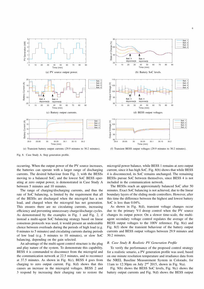
6
Time (min)
0 10 20 30 40 50 60 70 80 90
PV
Ge
ne
ratio
n (
kW
)
-1
0
1
2
3
4
5
(a) PV source output power.
Time (min)
0 10 20 30 40 50 60 70 80 90
Sta
te o
f C
harg
e (
%)
20
40
60
80Batt. 1
Batt. 2
Batt. 3
Batt. 4
Batt. 4
disconnectsBatt. 4
reconnects
(b) Battery SoC levels.
Time (min)
0 10 20 30 40 50 60 70 80 90
Batt
ery
Curr
ent
(A)
-20
-10
0
10
20Batt. 1
Batt. 2
Batt. 3
Batt. 4
Batt. 4
disconnectsBatt. 4
reconnects
(c) Battery output currents.
Time (min)
0 10 20 30 40 50 60 70 80 90
Outp
ut
Voltage (
V)
90
95
100
105
110Batt. 1
Batt. 2
Batt. 3
Batt. 4
Batt. 4
disconnects
Batt. 4
reconnects
(d) BESS output voltages.
Time (min)
29.9 29.95 30 30.05 30.1 30.15 30.2
Battery
Curr
ent (A
)
0
5
10
15
20Batt. 1
Batt. 2
Batt. 3
Batt. 4
(e) Transient battery output currents (29.9 minutes to 30.2 minutes).
Time (min)
29.9 29.95 30 30.05 30.1 30.15 30.2
Outp
ut V
oltage (
V)
90
95
100
105
110Batt. 1
Batt. 2
Batt. 3
Batt. 4
(f) Transient BESS output voltages (29.9 minutes to 30.2 minutes).
Fig. 8. Case Study A. Step generation profile.
occurring. When the output power of the PV source increases,
the batteries can operate with a larger range of discharging
currents. The desired behaviour from Fig. 3, with the BESSs
moving to a balanced SoC, and the lowest SoC BESS oper-
ating at zero output power, is demonstrated in Case Study A
between 5 minutes and 10 minutes.
The range of charging/discharging currents, and thus the
rate of SoC balancing, is limited by the requirement that all
of the BESSs are discharged when the microgrid has a net
load, and charged when the microgrid has net generation.
This ensures there are no circulating currents, increasing
efficiency and preventing unnecessary charge/discharge cycles.
As demonstrated by the examples in Fig. 1 and Fig. 2, if
instead a multi-agent SoC balancing strategy based on linear
consensus protocols was used, it would present an undesirable
choice between overloads during the periods of high load (e.g.
0 minutes to 5 minutes) and circulating currents during periods
of low load (e.g. 5 minutes to 10 minutes), or slow SoC
balancing, depending on the gain selected.
An advantage of the multi-agent control structure is the plug
and play nature of the system. To demonstrate this capability,
BESS 4 is commanded to disconnect from the microgrid and
the communication network at 22.5 minutes, and to reconnect
at 37.5 minutes. As shown in Fig. 8(c), BESS 4 goes from
charging to zero output current. Fig. 8(d) shows that this
causes an increase in the microgrid voltages. BESS 2 and
3 respond by increasing their charging rate to restore the
microgrid power balance, while BESS 1 remains at zero output
current, since it has high SoC. Fig. 8(b) shows that while BESS
4 is disconnected, its SoC remains unchanged. The remaining
BESSs pursue SoC between themselves, since BESS 4 is not
included in the communication network.
The BESSs reach an approximately balanced SoC after 50
minutes. Exact SoC balancing is not achieved, due to the linear
boundary layers of the sliding mode controllers. However, after
this time the difference between the highest and lowest battery
SoC is less than 0.04%.
As shown in Fig. 8(d), transient voltage changes occur
due to the primary V-I droop control when the PV source
changes its output power. On a slower time-scale, the multi-
agent secondary voltage control regulates the average of the
BESS output voltages to the 100V reference. Fig. 8(e) and
Fig. 8(f) show the transient behaviour of the battery output
currents and BESS output voltages between 29.9 minutes and
30.2 minutes.
B. Case Study B. Realistic PV Generation Profile
To verify the performance of the proposed control strategy
for a realistic senario, a PV generation profile was used, based
on one minute resolution temperature and irradiance data from
the NREL Baseline Measurement System in Colorado, for
11am to 12:30pm on July 2nd 2015, shown in Fig. 9(a).
Fig. 9(b) shows the BESS SoC levels, Fig. 9(c) shows the
battery output currents and Fig. 9(d) shows the BESS output

7
Time (min)
0 10 20 30 40 50 60 70 80 90
PV
Genera
tion (
kW
)
-1
0
1
2
3
4
5
(a) PV source output power.
Time (min)
0 10 20 30 40 50 60 70 80 90
Sta
te o
f C
harg
e (
%)
20
40
60
80Batt. 1
Batt. 2
Batt. 3
Batt. 4
Batt. 4
disconnectsBatt. 4
reconnects
(b) Battery SoC levels.
Time (min)
0 10 20 30 40 50 60 70 80 90
Batt
ery
Curr
ent
(A)
-20
-10
0
10
20Batt. 1
Batt. 2
Batt. 3
Batt. 4
Batt. 4
disconnectsBatt. 4
reconnects
(c) Battery output currents.
Time (min)
0 10 20 30 40 50 60 70 80 90
Outp
ut
Voltage (
V)
90
95
100
105
110Batt. 1
Batt. 2
Batt. 3
Batt. 4
Batt. 4
disconnectsBatt. 4
reconnects
(d) BESS output voltages.
Time (min)
41.9 41.95 42 42.05 42.1 42.15 42.2
Battery
Curr
ent (A
)
-10
-5
0
5
10Batt. 1
Batt. 2
Batt. 3
Batt. 4
(e) Transient battery output currents (41.9 minutes to 42.2 minutes).
Time (min)
41.9 41.95 42 42.05 42.1 42.15 42.2
Outp
ut V
oltage (
V)
90
95
100
105
110Batt. 1
Batt. 2
Batt. 3
Batt. 4
(f) Transient BESS output voltages (41.9 minutes to 42.2 minutes).
Fig. 9. Case Study B. Realistic PV generation profile.
voltages. Fig. 9(e) and Fig. 9(f) show the transient behaviour of
the battery output currents and BESS output voltages between
41.9 minutes and 42.2 minutes. As in Case Study A, (i) no
circulating currents, (ii) fast SoC balancing, (iii) no overload
and (iv) plug and play capability are all demonstrated.
IV. CONCLUSION
This paper has presented a multi-agent sliding mode control
strategy for SoC balancing between distributed DC microgrid
BESSs. The proposed control strategy provides significantly
improved operation compared to existing SoC balancing strate-
gies based on linear consensus protocols. By utilising the
full excess capacity of the BESSs, fast SoC balancing is
achieved without circulating currents. Eliminating circulat-
ing currents increases efficiency and reduces battery lifetime
degradation. Real-time digital simulation results have been
presented demonstrating the performance of the proposed
control strategy.
APPENDIX
This appendix provides a rigorous analysis of the conditions
under which the proposed multi-agent sliding mode control
strategy provides SoC synchronisation between the distributed
DC microgrid BESSs.
The dynamics of each BESS i ∈ V are described by the
following system of nonlinear equations:
xi(t) = fi(xi, ui),
si(t) = rTi xi(t), (7)
where xi(t) ∈ Rmi is the state of BESS i, ui(t) ∈ R is the
charging/discharging control signal and si(t) ∈ R is the SoC
of BESS i. In this case, the variation of the SoC is described
by the equation
si(t) = rTi fi(xi, ui). (8)
It is assumed that for all i ∈ V and all xi ∈ Rmi ,
rTi fi(xi, 0) = 0. (9)
Also, it is assumed that there exist functions
U1(ipuL , x), U2(i
puL , x), . . . , UN (ipuL , x) defined for all
ipuL ∈ [−ipumaxL , ipumax
L ] and xi ∈ Rmi such that,
−ipuL = rTi fi(
xi, Ui(ipuL , x)
)
. (10)
Let pi(t) = gi(xi, ui) be the output power of BESS i,It is assumed that the batteries have charging and discharg-
ing efficiencies between 0% and 100%. Let ǫ0 > 0 be some
given constant. Then,
si(t) ≤ −pi(t)
Ebatti
≤ (1 + ǫ0)si(t) if si(t) > 0,
si(t) ≤ −pi(t)
Ebatti
≤ (1− ǫ0)si(t) if si(t) < 0. (11)

8
Ebatti is the battery energy capacity. The difference be-
tween si(t) and − pi(t)Ebatti
is the per-unit charge loss of the
charge/discharge process.
Let P punet(t) :=
∑N
i=1pi(t)Ebatti
be the net microgrid
load/generation, normalised by the battery energy capacities.
Also, let S0 :=∑N
i=1 si(0) and,
P punet(t) :=
{
11+ǫ0
P punet(t), P pu
net(t) ≤ 0,1
1−ǫ0P punet(t), P pu
net(t) > 0.
The following constraints on the SoC of the BESSs must
be satisfied, to prevent overcharging/undercharging:
smin ≤ si(t) ≤ smax, ∀ i ∈ V, (12)
with given constants smax > smin > 0.
To satisfy this requirement, the following assumptions are
required: (a) The BESSs must begin within their allowed SoC
ranges,
smin < si(0) < smax, ∀ i ∈ V. (13)
(b) The BESSs must be able to supply/store the net charge
demanded from them. Therefore, for all T ≥ 0,
S0−
∫ T
0
P punet(t) dt ≤ Nsmax, S0−
∫ T
0
P punet(t) dt ≥ Nsmin,
(14)
(c) The microgrid must not approach a steady state with zero
demand. Therefore,∫ T
0
|P punet(t)|dt → ∞ as T → ∞. (15)
If condition (c) is not satisfied, SoC synchronisation may
require circulating currents.
The graph between the BESSs G(V, E) is connected and
bidirectional, as specified in Section II. It is assumed that aiis chosen such that the distributed average current consensus
protocol is much faster than the SoC dynamics. Therefore, the
local estimates of the average per-unit current of the BESSs
participating in the droop control can be treated as being
equal to a common value, i.e. ipuLi(t) = ipu∗L (t), ∀i ∈ V .
This is justified by the observation that even with low band-
width communications, the speed of the dynamic average
consensus protocol will be on the order of seconds, while
at the highest practical rate a BESS will take minutes to be
charged/discharged.
The following sliding mode controller is introduced for each
BESS:
ui(t) =
Ui (ipuLi(t), xi(t)) , si(t) ≥ Ai(t) and ipuLi(t) > 0,
Ui (ipuLi(t), xi(t)) , si(t) ≤ Ai(t) and ipuLi(t) < 0,
0, otherwise.
(16)
The closed-loop system belongs to the class of hybrid dynam-
ical systems [33], [34]. Note that this controller is equivalent
to (6).
Finally, it is assumed that there exists a constant ǫ > 0, such
that if P punet(t) 6= 0, ipu∗L (t) ∈ [−ipumax
L ,−ǫ] ∪ [ǫ, ipumaxL ].
Otherwise, all of the BESSs would need to operate at their
maximum charging or discharging current, and they would
have no excess current capacity to use for SoC balancing
(without introducing circulating currents).
Theorem A.1: Consider the system (7), (8) with the con-
troller (16) and some functions P punet(t), i
pu∗L (t). Suppose that
the specified assumptions hold. Then, the constraint (12) holds,
and limt→∞(si(t)− sj(t)) = 0, for all i, j.
Proof of Theorem A.1: The following Lyapunov function is
introduced (see [35]):
V (s1(t), s2(t), . . . , sN (t)) =
N∑
i=1
|si(t)−Ai(t)|.
Clearly, V (s1(t), s2(t), . . . , sN (t)) ≥ 0, and
V (s1(t), s2(t), . . . , sN (t)) = 0 if and only if
s1(t) = s2(t) = · · · = sN (t).
Furthermore, let V (s1(t), s2(t), . . . , sN (t)) be the derivative
of V (s1(t), s2(t), . . . , sN (t)) along trajectories of the system
(7), (8) with the controller (16). Then, it follows from the
structure of the controller (16) that V (s1(t), s2(t), . . . , sN (t))is always non-positive. Also, when P pu
net(t) 6= 0 it follows that
V (s1(t), s2(t), . . . , sN (t)) ≤ − ǫN
. This, with (15), implies
that V (s1(t), s2(t), . . . , sN (t)) → 0 as t → ∞. Therefore,
limt→∞
(
si(t)− sj(t))
= 0 ∀ i, j.
The constraint (12) follows from the conditions in (13), (14).
This completes the proof of Theorem A.1, i.e. the SoC levels
of the distributed BESSs synchronise under the proposed
control strategy.
REFERENCES
[1] C. Restrepo, A. Salazar, H. Schweizer, and A. Ginart, “ResidentialBattery Storage: Is the Timing Right?” IEEE Electrification Magazine,vol. 3, no. 3, pp. 14–21, Sep. 2015.
[2] M. S. Whittingham, “History, Evolution, and Future Status of EnergyStorage,” Proceedings of the IEEE, vol. 100, no. Special CentennialIssue, pp. 1518–1534, 2012.
[3] J. J. Justo, F. Mwasilu, J. Lee, and J.-W. Jung, “AC-microgrids versusDC-microgrids with distributed energy resources: A review,” Renewableand Sustainable Energy Reviews, vol. 24, pp. 387–405, Aug. 2013.
[4] R. H. Lasseter, “MicroGrids,” in 2002 IEEE Power Engineering SocietyWinter Meeting. Conference Proceedings (Cat. No.02CH37309), vol. 1,2002, pp. 305–308.
[5] K. Strunz, E. Abbasi, and D. N. Huu, “DC Microgrid for Wind and SolarPower Integration,” IEEE Journal of Emerging and Selected Topics inPower Electronics, vol. 2, no. 1, pp. 115–126, Mar. 2014.
[6] H. Ikebe, “Power Systems for Telecommunications in the IT Age,” inTelecommunications Energy Conference, 2003. INTELEC ’03. The 25thInternational, Oct. 2003, pp. 1–8.
[7] J. M. Guerrero, J. C. Vasquez, J. Matas, L. G. de Vicuna, and M. Castilla,“Hierarchical Control of Droop-Controlled AC and DC Microgrids-AGeneral Approach Toward Standardization,” IEEE Trans. Ind. Electron.,vol. 58, no. 1, pp. 158–172, Jan. 2011.
[8] J. Schiffer, D. U. Sauer, H. Bindner, T. Cronin, P. Lundsager, andR. Kaiser, “Model prediction for ranking lead-acid batteries according toexpected lifetime in renewable energy systems and autonomous power-supply systems,” Journal of Power Sources, vol. 168, no. 1, pp. 66–78,May 2007.
[9] T. Morstyn, B. Hredzak, and V. G. Agelidis, “Distributed CooperativeControl of Microgrid Storage,” IEEE Trans. Power Syst., vol. 30, no. 5,pp. 2780–2789, Oct. 2014.
[10] L. Meng, T. Dragicevic, J. Vasquez, J. Guerrero, and E. R. Sanseverino,“Hierarchical control with virtual resistance optimization for efficiencyenhancement and State-of-Charge balancing in DC microgrids,” 2015IEEE 1st International Conference on Direct Current Microgrids,ICDCM 2015, pp. 1–6, Jun. 2015.
9
[11] T. Dragicevic, J. M. Guerrero, J. C. Vasquez, and D. Skrlec, “Super-visory Control of an Adaptive-Droop Regulated DC Microgrid WithBattery Management Capability,” IEEE Trans. Power Electron., vol. 29,no. 2, pp. 695–706, Feb. 2014.
[12] S. D. J. McArthur, E. M. Davidson, V. M. Catterson, A. L. Dimeas,N. D. Hatziargyriou, F. Ponci, and T. Funabashi, “Multi-Agent Systemsfor Power Engineering Applications-Part I: Concepts, Approaches, andTechnical Challenges,” IEEE Trans. Power Syst., vol. 22, no. 4, pp.1743–1752, Nov. 2007.
[13] Y. Simmhan, A. G. Kumbhare, B. Cao, and V. Prasanna, “An Analysisof Security and Privacy Issues in Smart Grid Software Architectureson Clouds,” in 2011 IEEE 4th International Conference on CloudComputing, Jul. 2011, pp. 582–589.
[14] F. L. Lewis, H. Zhang, K. Hengster-Movric, and A. Das, CooperativeControl of Multi-Agent Systems, ser. Communications and ControlEngineering. London: Springer London, 2014.
[15] A. Bidram, A. Davoudi, F. L. Lewis, and J. M. Guerrero, “DistributedCooperative Secondary Control of Microgrids Using Feedback Lin-earization,” IEEE Trans. Power Syst., vol. 28, no. 3, pp. 3462–3470,Aug. 2013.
[16] J. W. Simpson-Porco, F. Dorfler, and F. Bullo, “Synchronization andpower sharing for droop-controlled inverters in islanded microgrids,”Automatica, vol. 49, no. 9, pp. 2603–2611, Sep. 2013.
[17] V. Nasirian, S. Moayedi, A. Davoudi, and F. L. Lewis, “DistributedCooperative Control of DC Microgrids,” IEEE Trans. Power Electron.,vol. 30, no. 4, pp. 2288–2303, Apr. 2015.
[18] J. Zhao and F. Dorfler, “Distributed control and optimization in DCmicrogrids,” Automatica, vol. 61, pp. 18–26, Aug. 2015.
[19] D. Florian, J. W. Simpson-porco, and F. Bullo, “Breaking the hierarchy:Distributed control & economic optimality in microgrids,” IEEE Trans.Control Netw. Syst., vol. PP, no. 99, pp. 1–1, 2014.
[20] S. Bolognani and S. Zampieri, “A Distributed Control Strategy for Re-active Power Compensation in Smart Microgrids,” IEEE Trans. Autom.Control, vol. 58, no. 11, pp. 2818–2833, Nov. 2013.
[21] T. Dragicevic, J. M. Guerrero, and J. C. Vasquez, “A Distributed ControlStrategy for Coordination of an Autonomous LVDC Microgrid Basedon Power-Line Signaling,” IEEE Trans. Ind. Electron., vol. 61, no. 7,pp. 3313–3326, Jul. 2014.
[22] T. Dragicevic, X. Lu, J. C. Vasquez, and J. M. Guerrero, “DCMicrogrids–Part I: A Review of Control Strategies and StabilizationTechniques,” IEEE Trans. Power Electron., vol. 31, no. 7, pp. 4876– 4891, Sep. 2015.
[23] T. Morstyn, B. Hredzak, G. D. Demetriades, and V. G. Agelidis, “UnifiedDistributed Control for DC Microgrid Operating Modes,” IEEE Trans.Power Syst., vol. 31, no. 1, pp. 802–812, Mar. 2015.
[24] T. Morstyn, B. Hredzak, and V. G. Agelidis, “Cooperative Multi-Agent Control of Heterogeneous Storage Devices Distributed in a DCMicrogrid,” IEEE Trans. Power Syst., vol. 31, no. 4, pp. 2974–2986,Sep. 2015.
[25] T. Morstyn, B. Hredzak, V. G. Agelidis, and G. Demetriades, “Cooper-ative control of DC microgrid storage for energy balancing and equalpower sharing,” in 2014 Australasian Universities Power EngineeringConference (AUPEC), Sep. 2014, pp. 1–6.
[26] T. Morstyn, B. Hredzak, and V. G. Agelidis, “Communication delayrobustness for multi-agent state of charge balancing between distributedAC microgrid storage systems,” in 2015 IEEE Conference on ControlApplications (CCA), Sep. 2015, pp. 181–186.
[27] C. Li, D. Dragicevic, M. G. Plaza, F. Andrade, J. C. Vasquez, andJ. M. Guerrero, “Multiagent based distributed control for state-of-chargebalance of distributed energy storage in DC microgrids,” in IECON 2014- 40th Annual Conference of the IEEE Industrial Electronics Society,Oct. 2014, pp. 2180–2184.
[28] C. Li, T. Dragicevic, J. C. Vasquez, J. M. Guerrero, and E. A. A.Coelho, “Multi-agent-based distributed state of charge balancing controlfor distributed energy storage units in AC microgrids,” in 2015 IEEEApplied Power Electronics Conference and Exposition (APEC), Mar.2015, pp. 2967–2973.
[29] P. Sanchis, A. Ursaea, E. Gubia, and L. Marroyo, “Boost DC-ACInverter: A New Control Strategy,” IEEE Trans. Power Electron., vol. 20,no. 2, pp. 343–353, Mar. 2005.
[30] R. Olfati-saber, D. P. Spanos, and R. M. Murray, “Dynamic Consensusfor Mobile Networks,” in 2005 IFAC World Congress, Jul. 2005.
[31] J.-J. E. Slotine and W. Li, Applied Nonlinear Control. EnglewoodCliffs, New Jersey: Prentice Hall, 1991.
[32] T. Kim and W. Qiao, “A Hybrid Battery Model Capable of CapturingDynamic Circuit Characteristics and Nonlinear Capacity Effects,” IEEETrans. Energy Convers., vol. 26, no. 4, pp. 1172–1180, Dec. 2011.
[33] A. S. Matveev and A. V. Savkin, Qualitative Theory of Hybrid Dynam-ical Systems. Boston: Birkhauser, 2000.
[34] A. V. Savkin and R. J. Evans, Hybrid Dynamical Systems: Controllerand Sensor Switching Problems. Boston: Birkhauser, 2002.
[35] I. R. Petersen, V. A. Ugrinovskii, and A. V. Savkin, Robust ControlDesign Using H-infinity Methods. London: Springer-Verlag, 2000.
Thomas Morstyn (S’14-M’16) received the B.E.(Hon.) degree from the University of Melbourne,Australia, in 2011, and the PhD degree from theUniversity of New South Wales, Australia, in 2016,both in electrical engineering.
He worked as an electrical engineer in the RioTinto Technology and Innovation Group between2012 and 2014. He is currently an Oxford MartinFellow in the Department of Engineering Science atthe University of Oxford. His current research inter-ests include multi-agent control and optimisation for
the integration of distributed renewable generation and energy storage systemsinto power networks.
Andrey V. Savkin (M’97-SM’98) received the M.S.degree in mathematics and the Ph.D. degree inapplied mathematics from The Leningrad University,Leningrad, Russia, in 1987 and 1991, respectively.Since 2000, he has been a Professor in the Schoolof Electrical Engineering and Telecommunications,The University of New South Wales, Sydney, NSW,Australia. His current research interests include ro-bust control and filtering, robotics, networked con-trol systems, control of power systems and the appli-cation of control and signal processing to biomedical
engineering and medicine. Dr. Savkin has been an associate editor for severalinternational journals and conferences.
Branislav Hredzak (M’98-SM’13) received theB.Sc./M.Sc. degree from the Technical Universityof Kosice, Slovak Republic, in 1993, and the Ph.D.degree from Napier University of Edinburgh, U.K.,in 1997, all in electrical engineering.
He was a Lecturer and a Senior Researcher in Sin-gapore from 1997 to 2007. He is currently a SeniorLecturer in the School of Electrical Engineering andTelecommunications, The University of New SouthWales, Sydney, NSW, Australia. His current researchinterests include hybrid storage technologies and
advanced control systems for power electronics and storage systems.
Vassilios G. Agelidis (S’89-M’91-SM’00-F’16) wasborn in Serres, Greece. He received the B.Eng.degree in electrical engineering from the DemocritusUniversity of Thrace, Thrace, Greece, in 1988, theM.S. degree in applied science from ConcordiaUniversity, Montreal, QC, Canada, in 1992, and thePh.D. degree in electrical engineering from CurtinUniversity, Perth, Australia, in 1997. He has workedat Curtin University (1993–1999), University ofGlasgow, U.K. (2000–2004), Murdoch University,Perth, Australia (2005–2006), the University of Syd-
ney, Australia (2007–2010), and the University of New South Wales (UNSW),Sydney, Australia (2010–2016). He is currently a professor at the Departmentof Electrical Engineering, Technical University of Denmark.
Dr. Agelidis received the Advanced Research Fellowship from the U.K.’sEngineering and Physical Sciences Research Council in 2004. He was theVice-President Operations within the IEEE Power Electronics Society from2006 to 2007. He was an AdCom Member of the IEEE Power ElectronicsSociety from 2007 to 2009 and the Technical Chair of the 39th IEEE PowerElectronics Specialists Conference, Rhodes, Greece, 2008.
View publication statsView publication stats