Embed Size (px)
Citation preview

Multi-Agent Management of Crowds to Avoid Stampedes in Long Queues
Thesis submitted in partial fulfillment
of the requirements for the degree of
MS by Research
in
Computer Science Engineering
by
Sindhu Kolli
Center for Data Engineering
International Institute of Information Technology
Hyderabad - 500 032, INDIA
July 2014

Copyright c© Sindhu Kolli, 2014
All Rights Reserved

International Institute of Information Technology
Hyderabad, India
CERTIFICATE
It is certified that the work contained in this thesis, titled “Multi-Agent Management of Crowds to
Avoid Stampedes in Long Queues” by Sindhu Kolli, has been carried out under my supervision and is
not submitted elsewhere for a degree.
Date Adviser: Prof. Kamalakar Karlapalem

To My Family

Acknowledgments
I would like to take this opportunity to sincerely thank my guide Prof. Kamalakar Karlapalem, for
his immense support and constant guidance, without which this thesis would not have been possible.
Working under his guidance has been a great learning experience. I thank him for encouraging and
helping me understand the subject better.
I would like to thank the institute for providing a great atmosphere and support to carry out my
research. I would like to thank my friends Anusha Balusu, Anusha Konduri, Archita, Susmitha and
Vasudha for their support and encouragement through out my B.Tech and specially Anisha, Apeksha
and Shipra for spending some of their valuable time discussing and reviewingmy work. I thank them
for all the motivation.
Finally, I would like to thank my family for being supportive at every step of my life. I am grateful
to my father, who always believed in me, who always made time to discuss my education, for his
inspiration and motivation. I thank my mother, for all her love and affection. And my little sister, for
being a great friend and, for her lovely and thoughtful advices.
v
Abstract
In places of reverence, wherein large crowds gather to have small duration of time for individual
solace, there is a long queue of people waiting for their turn. A typical example of this scenario is a
temple wherein each person visiting the temple, would want to spend a small amount of time to offer
prayers in front of a deity. During auspicious occasions there will be hundreds of thousands or more
anxious people queuing at the temple wanting to pray. Some other examples would be long shopping
queues and queuing at ticketing counters for large crowd gathering events (like sports, music concerts).
A crowd management force (that is police or security) at such events, are present to monitor the crowd
and prevent any crowd disasters. Yet, there have been cases of stampedes with significant loss of life
and trauma in such occasions because of lack of efficiency in the management of crowds. This presents
us with a scenario where a multi-agent based system can be used to help improve the efficiency of crowd
management at temples.
In this thesis, we develop a multi-agent based system for simulating the scenario of crowding in long
queues at temples. We focus on how introducing external agents in this scenario would help manage
the crowd better. First, we introduce MAMAC (Multi-Agent MAnagement of Crowd), a set of robotic
agents that can move at a height above the queue, (i) to provide direction and monitor the crowds,
and (iii) to avoid occurrences of stampedes. We then focus on increasingthe efficiency of the robotic
agents. A method of movement has been developed that can be used by these robotic agents to ensure
smooth flow of the crowd. Finally, we present a solution that uses only the required number of robotic
agents that can manage the crowd to achieve a stampede free flow. We evaluate the efficiency of crowd
management by conducting various experiments on the multi-agent simulation showing the results of
robotic-agents avoiding the possibility of stampedes to occur.
vi

Contents
Chapter Page
1 Introduction . . . . . . . . . . . . . . . . . . . . . . . . . . . . . . . . . . . . . . . . . . 11.1 MAMAC (Multi-Agent MAnagement of Crowd) . . . . . . . . . . . . . . . . . .. . 2
1.1.1 Robotic Agents for Crowd Management . . . . . . . . . . . . . . . . . . . . .21.1.2 A Method of Movement for Robotic Agents . . . . . . . . . . . . . . . . . . . 21.1.3 Required Number of Robotic Agents for Crowd Management . . . . . . .. . 3
1.2 Overview of the thesis . . . . . . . . . . . . . . . . . . . . . . . . . . . . . . . . . . 3
2 Related Work . . . . . . . . . . . . . . . . . . . . . . . . . . . . . . . . . . . . . . . . . 52.1 Crowd Simulation . . . . . . . . . . . . . . . . . . . . . . . . . . . . . . . . . . . . . 5
2.1.1 Multi-agent based crowd simulation systems . . . . . . . . . . . . . . . . . . 62.2 Crowd Disasters: Crowd Management . . . . . . . . . . . . . . . . . . . . . .. . . . 7
2.2.1 Crowd Management . . . . . . . . . . . . . . . . . . . . . . . . . . . . . . . 82.2.2 Crowd Management at Temples . . . . . . . . . . . . . . . . . . . . . . . . . 9
3 MAMAC: Multi-Agent System for Management of Crowd at Temples. . . . . . . . . . . . 103.1 Description of scenario of crowding at Temples . . . . . . . . . . . . . . . .. . . . . 103.2 Multi-Agent Simulation Framework for Queuing at Temples . . . . . . . . . . . .. . 123.3 Simulation Model for MAMAC . . . . . . . . . . . . . . . . . . . . . . . . . . . . . 13
3.3.1 Human Agents Model . . . . . . . . . . . . . . . . . . . . . . . . . . . . . . 133.3.1.1 Heterogeneous Human Agents . . . . . . . . . . . . . . . . . . . . 133.3.1.2 Force Model . . . . . . . . . . . . . . . . . . . . . . . . . . . . . . 133.3.1.3 Human Agents Parameter Update . . . . . . . . . . . . . . . . . . . 15
3.3.2 Crowd Managing Robotic Agents Model . . . . . . . . . . . . . . . . . . . . 15
4 Management of Crowd in Long Queues using Crowd Managing Agents. . . . . . . . . . . . 164.1 States of the Queue at Temples and Calculation of Prayer time (δ) . . . . . . . . . . . 194.2 Method of Movement for Crowd Managing Agents . . . . . . . . . . . . . . .. . . . 234.3 Results . . . . . . . . . . . . . . . . . . . . . . . . . . . . . . . . . . . . . . . . . . . 244.4 Discussion . . . . . . . . . . . . . . . . . . . . . . . . . . . . . . . . . . . . . . . . .27
5 An Extended Method of Movement for Crowd Managing Agents. . . . . . . . . . . . . . . 295.1 A Different Perspective of determining Various States of Queuing . . .. . . . . . . . 305.2 Extended Method of Movement for Robotic Agents . . . . . . . . . . . . . . .. . . . 315.3 Results . . . . . . . . . . . . . . . . . . . . . . . . . . . . . . . . . . . . . . . . . . . 33
vii

viii CONTENTS
5.4 Discussion . . . . . . . . . . . . . . . . . . . . . . . . . . . . . . . . . . . . . . . . .38
6 Required Number of Crowd Managing Robotic Agents. . . . . . . . . . . . . . . . . . . . 396.1 Using a Required Number of Crowd Managing Agents . . . . . . . . . . . . .. . . . 396.2 Determining the required number of robots . . . . . . . . . . . . . . . . . . . . .. . 416.3 Results . . . . . . . . . . . . . . . . . . . . . . . . . . . . . . . . . . . . . . . . . . . 426.4 Discussion . . . . . . . . . . . . . . . . . . . . . . . . . . . . . . . . . . . . . . . . .45
7 Conclusions and Future Work. . . . . . . . . . . . . . . . . . . . . . . . . . . . . . . . . 54
Bibliography . . . . . . . . . . . . . . . . . . . . . . . . . . . . . . . . . . . . . . . . . . . . 56

List of Figures
Figure Page
3.1 Robots monitoring the crowd using their thermal sensor’s view range . . .. . . . . . . 113.2 A robot shows Red signal, when it determines high density in its detection range that
leads to a state of congestion in the queue. . . . . . . . . . . . . . . . . . . . . . . .. 113.3 Forces Affecting the Human AgentHi within its influence range of radiusr . . . . . . 14
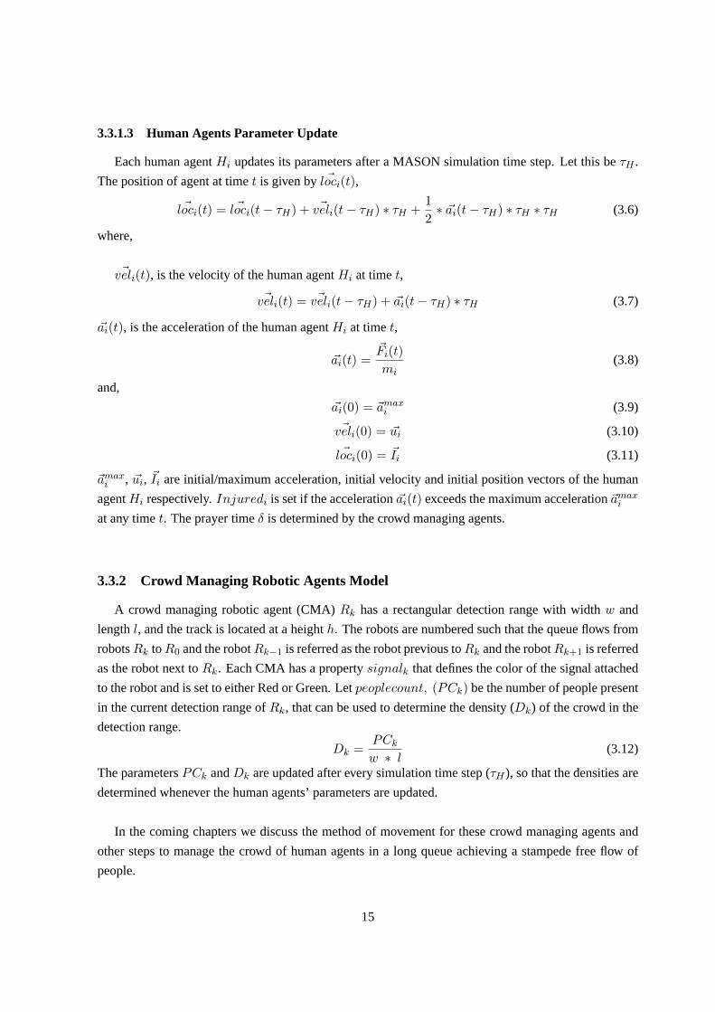
4.1 Fruin’s Levels of Service (FLOS) [28]: Flow rate (Number of peopleper width [inmeters], per time [in minutes]) for each level is, FLOS A - less than 23 people per meterper min, FLOS B - between 23-33 people per meter per min, FLOS C - between 33-49people per meter per min, FLOS D - between 49-66 people per meter per min, FLOS E- between 66-82 people per meter per min, and LOS F - highly variable. With increasein the level, there is increase in the density of crowd. . . . . . . . . . . . . . . . .. . 17
4.2 Causes of injury/death during a stampede . . . . . . . . . . . . . . . . . . . . .. . . 184.3 Various states of queuing at temples. . . . . . . . . . . . . . . . . . . . . . . . .. . . 204.4 Force(F) exerted by people increases asλ increases andµ decreases. It is maximum
whenλ is maximum andµ is minimum. It is minimum whenλ is minimum andµ ismaximum. The dark gray shaded region represents congestion leading to stampede. . . 21
4.5 Various States of Queuing: (a) Free Flow, (b) Constant Flow, (c) Congestion Flow, and(d) Stampede. . . . . . . . . . . . . . . . . . . . . . . . . . . . . . . . . . . . . . . . 22
4.6 Robot are numbered starting from the main temple arena to the queue entrance. R0 isplaced at the entrance of main temple arena andRn−1 is placed at the entrance of thequeue. . . . . . . . . . . . . . . . . . . . . . . . . . . . . . . . . . . . . . . . . . . . 24
4.7 Series of actions of robots to reduce congestion. . . . . . . . . . . . . . .. . . . . . . 264.8 The state of the queue would be determined as congestion flow, but not all the areas of
the queue are congested. . . . . . . . . . . . . . . . . . . . . . . . . . . . . . . . .. 27
5.1 Various states of a queue between two robotsRk andRk−1 . . . . . . . . . . . . . . . 305.2 A simulation state of queuing at temples with crowd managing agents using the extended
method of movement for managing the crowd. . . . . . . . . . . . . . . . . . . . . . .335.3 The robotsR0, R1, R2, R3 andR4 are static and show Green. In this state people in the
main temple arena are allowed forδmax time to offer their prayers. . . . . . . . . . . . 335.4 This shows that the main temple arena is full and the robotR0 shows Red for aδmax
time. As there is increase in the flow rate (people entering per minute), people enteringin this state are accumulated at robotR0 until they are allowed into the main templearena for prayers. . . . . . . . . . . . . . . . . . . . . . . . . . . . . . . . . . . .. . 34
ix
x LIST OF FIGURES
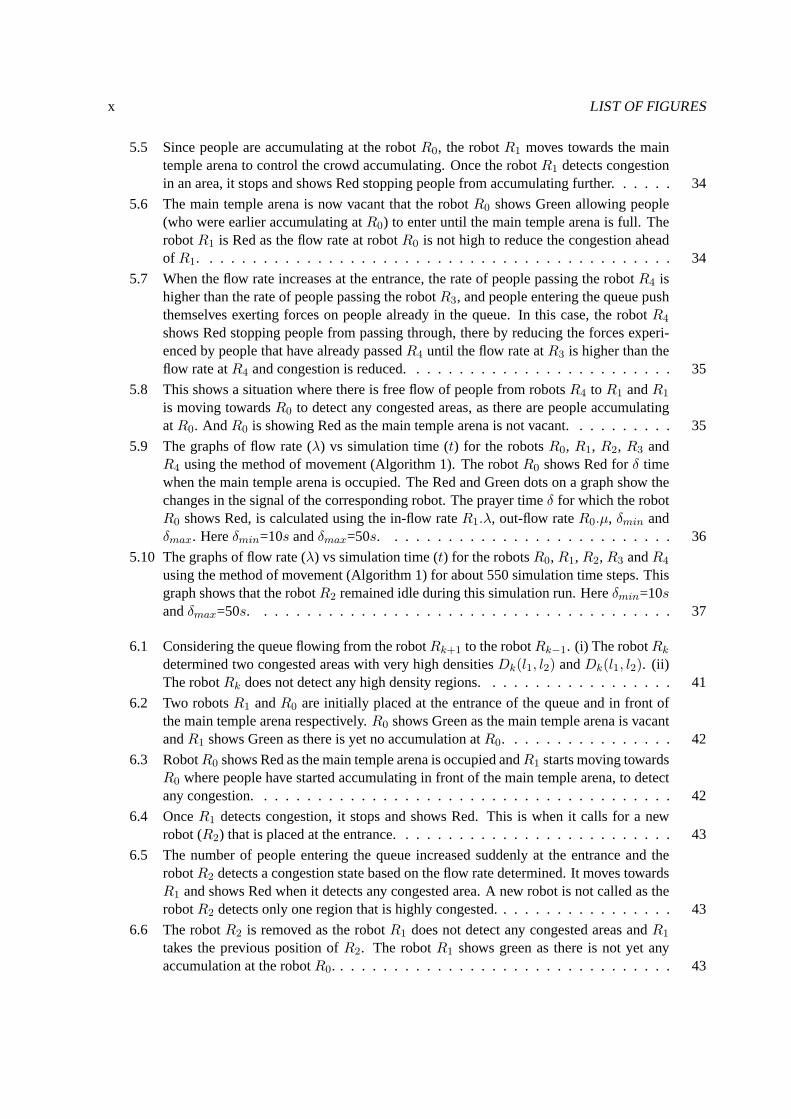
5.5 Since people are accumulating at the robotR0, the robotR1 moves towards the maintemple arena to control the crowd accumulating. Once the robotR1 detects congestionin an area, it stops and shows Red stopping people from accumulating further. . . . . . 34
5.6 The main temple arena is now vacant that the robotR0 shows Green allowing people(who were earlier accumulating atR0) to enter until the main temple arena is full. TherobotR1 is Red as the flow rate at robotR0 is not high to reduce the congestion aheadof R1. . . . . . . . . . . . . . . . . . . . . . . . . . . . . . . . . . . . . . . . . . . . 34
5.7 When the flow rate increases at the entrance, the rate of people passing the robotR4 ishigher than the rate of people passing the robotR3, and people entering the queue pushthemselves exerting forces on people already in the queue. In this case, the robotR4
shows Red stopping people from passing through, there by reducing theforces experi-enced by people that have already passedR4 until the flow rate atR3 is higher than theflow rate atR4 and congestion is reduced. . . . . . . . . . . . . . . . . . . . . . . . . 35
5.8 This shows a situation where there is free flow of people from robotsR4 to R1 andR1
is moving towardsR0 to detect any congested areas, as there are people accumulatingatR0. AndR0 is showing Red as the main temple arena is not vacant. . . . . . . . . . 35
5.9 The graphs of flow rate (λ) vs simulation time (t) for the robotsR0, R1, R2, R3 andR4 using the method of movement (Algorithm 1). The robotR0 shows Red forδ timewhen the main temple arena is occupied. The Red and Green dots on a graph show thechanges in the signal of the corresponding robot. The prayer timeδ for which the robotR0 shows Red, is calculated using the in-flow rateR1.λ, out-flow rateR0.µ, δmin andδmax. Hereδmin=10s andδmax=50s. . . . . . . . . . . . . . . . . . . . . . . . . . . 36
5.10 The graphs of flow rate (λ) vs simulation time (t) for the robotsR0, R1, R2, R3 andR4
using the method of movement (Algorithm 1) for about 550 simulation time steps. Thisgraph shows that the robotR2 remained idle during this simulation run. Hereδmin=10sandδmax=50s. . . . . . . . . . . . . . . . . . . . . . . . . . . . . . . . . . . . . . . 37
6.1 Considering the queue flowing from the robotRk+1 to the robotRk−1. (i) The robotRk
determined two congested areas with very high densitiesDk(l1, l2) andDk(l1, l2). (ii)The robotRk does not detect any high density regions. . . . . . . . . . . . . . . . . . 41
6.2 Two robotsR1 andR0 are initially placed at the entrance of the queue and in front ofthe main temple arena respectively.R0 shows Green as the main temple arena is vacantandR1 shows Green as there is yet no accumulation atR0. . . . . . . . . . . . . . . . 42
6.3 RobotR0 shows Red as the main temple arena is occupied andR1 starts moving towardsR0 where people have started accumulating in front of the main temple arena, to detectany congestion. . . . . . . . . . . . . . . . . . . . . . . . . . . . . . . . . . . . . . . 42
6.4 OnceR1 detects congestion, it stops and shows Red. This is when it calls for a newrobot (R2) that is placed at the entrance. . . . . . . . . . . . . . . . . . . . . . . . . . 43
6.5 The number of people entering the queue increased suddenly at the entrance and therobotR2 detects a congestion state based on the flow rate determined. It moves towardsR1 and shows Red when it detects any congested area. A new robot is not called as therobotR2 detects only one region that is highly congested. . . . . . . . . . . . . . . . . 43
6.6 The robotR2 is removed as the robotR1 does not detect any congested areas andR1
takes the previous position ofR2. The robotR1 shows green as there is not yet anyaccumulation at the robotR0. . . . . . . . . . . . . . . . . . . . . . . . . . . . . . . . 43

LIST OF FIGURES xi
6.7 The graphs of flow rate (λ) vs simulation time (t′) for the robotsR0, R1 andR2 usingthe method described in Algorithm 2 for moving and using the method described inAlgorithm 3 to add or remove a robot. Here, the robotR2 is called at a later stage. . . . 44
6.8 The graphs of flow rate (λ) vs simulation time (t′) for the entrance and robotsR0 andR1 from t′=0s to t′=70s. . . . . . . . . . . . . . . . . . . . . . . . . . . . . . . . . . 46
6.9 The graphs of flow rate (λ) vs simulation time (t′) for the entrance and robotsR0, R1
andR2 from t′=60s to t′=130s. . . . . . . . . . . . . . . . . . . . . . . . . . . . . . . 476.10 The graphs of flow rate (λ) vs simulation time (t′) for the entrance and robotsR0, R1
andR2 from t′=120s to t′=220s. . . . . . . . . . . . . . . . . . . . . . . . . . . . . . 486.11 The graphs of flow rate (λ) vs simulation time (t′) for the entrance and robotsR0 and
R1 from t′=220s to t′=290s. . . . . . . . . . . . . . . . . . . . . . . . . . . . . . . . 496.12 The graphs of flow rate (λ) for the robotsR0,R1 andR2 vs. simulation time (t′) of about
300 simulation time steps. The robotR2 is added to the track at time stept′=81s. TherobotR1 is removed at time stept′=214s there by monitoring the area from entrance ofthe queue to the main temple arena. . . . . . . . . . . . . . . . . . . . . . . . . . . . 50
6.13 These graphs of prayer time (δ) determined vs. simulation time (t) of about 300 simu-lation time steps, compares the scenario in which no crowd managing agents areusedto manage the queue, with the scenario in which crowd managing agents are used tomonitor the queue. . . . . . . . . . . . . . . . . . . . . . . . . . . . . . . . . . . . . 52
List of Tables
Table Page
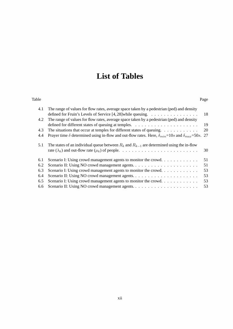
4.1 The range of values for flow rates, average space taken by a pedestrian (ped) and densitydefined for Fruin’s Levels of Service [4,28]while queuing. . . . . . . .. . . . . . . . 18
4.2 The range of values for flow rates, average space taken by a pedestrian (ped) and densitydefined for different states of queuing at temples. . . . . . . . . . . . . . . .. . . . . 19
4.3 The situations that occur at temples for different states of queuing. . .. . . . . . . . . 204.4 Prayer timeδ determined using in-flow and out-flow rates. Here,δmin=10s andδmax=50s. 27
5.1 The states of an individual queue betweenRk andRk−1 are determined using the in-flowrate (λk) and out-flow rate (µk) of people. . . . . . . . . . . . . . . . . . . . . . . . . 30
6.1 Scenario I: Using crowd management agents to monitor the crowd. . . . . .. . . . . . 516.2 Scenario II: Using NO crowd management agents. . . . . . . . . . . . . . .. . . . . . 516.3 Scenario I: Using crowd management agents to monitor the crowd. . . . . .. . . . . . 536.4 Scenario II: Using NO crowd management agents. . . . . . . . . . . . . . .. . . . . . 536.5 Scenario I: Using crowd management agents to monitor the crowd. . . . . .. . . . . . 536.6 Scenario II: Using NO crowd management agents. . . . . . . . . . . . . . .. . . . . . 53
xii
Chapter 1
Introduction
Everyday hundreds of events are held across the world which attract acrowd. ‘A crowd’ has multiple
vague definitions [15,51,53,57,59,80,86], more often described around the concept of a crowd beinga
large gathering of people. In order to successfully manage a crowd at a particular event, it is important
to distinguish different types of crowd [13]. The key criteria characterizing a crowd include: size, den-
sity, time, collectivity and novelty. Momboisse (1967) [55] distinguishes fourtypes of crowd: Casual,
Conventional, Expressive and Aggressive. We focus on ‘conventional’ crowds, which are the ones with
members gathered for a specific purpose or to observe a specific event,that is with crowd members who
share common interests. One such scenario that is referred to in this thesis is, a long queue of pedes-
trians (at temples) flowing in a specific direction sharing a common goal (offering prayers in front of a
deity).
In the scenario crowding at temples, long queues usually occur when people come to pray to a deity
in first come first serve manner. When very few people visit the temple, there is no waiting with free
flow of people and each person can spend substantial amount of time in front of the deity to pray. But
on auspicious occasions, even though there is restriction on amount of time aperson spends in front of
a deity, the queue is highly dense with many people people wanting to pray, that(i) the queue moves
very slowly, (ii) people get tired (some of them might be fasting) and (iii) severe congestion could lead
to stampede due to over enthusiastic people pushing themselves with force into the queue. Forces, as
a result of being both propagated and additive in the direction in which they are exerted, are location
specific [43, 44]. That is, most injuries occur either at the front of a crowd, where the forces are most
concentrated, or in the center of a crowd, where forces from individuals pushing off a wall combine with
forces from individuals pushing from the back [27]. By the time the crowdmanagement force (police
or security) at temples notices the stampede, the situation would have already gotten worse. Therefore,
it is important to manage the crowd in long queues by detecting and reducing congestion as soon as it
occurs. This motivated us to introduce external agents which help to efficiently manage the crowd and
reduce congestion in this scenario.
1

1.1 MAMAC (Multi-Agent MAnagement of Crowd)
Our solution is to deploy MAMAC, a multi-agent management system for managingcrowds in long
queues at temples. The model used for the simulation of crowds is based on asocial force model
by Helbing [38]. With the motivation of utilizing robotic agents to enhance the crowd management
techniques, this system was built in three steps: (i) a simulation system was developed to generate
crowds in long queues and a set of robotic agents are introduced for crowd management, (ii) a method
of movement for the robotic agents is presented in order to manage the flow ofthe crowd, and finally (iii)
a solution is provided to be able to use only a required number of robotic agents for crowd management
in long queues. The main contributions of this dissertation are as follows:
1.1.1 Robotic Agents for Crowd Management
Management of crowd in long queues is an important issue that is addressed in this dissertation. In
general, the crowd management force (police or security) at temples is notcapable of detecting con-
gested areas or any disturbances in the crowd as soon as they occurs.By the time, the situation of a
stampede comes into notice, it would have already gotten worse that the stampede continues to occur
prior to the instructions of crowd management force. This motivated us to introduce robots moving at a
height above the queue that are capable of: (i) monitoring the crowd usingthermal imaging sensors, (ii)
estimating the congestion levels and detecting disturbances as soon as they occur in the crowd, and (iii)
taking proactive measures to space out the people in the queue to reduce congestion.
A multi-agent based simulation has been developed to simulate the crowd in long queues at tem-
ples. The robots capable of managing the crowd are introduced into this simulation as crowd managing
robotic-agents. These robotic agents are placed at equal distances from each other on a track located at
a height above the queue. They continuously move in their assigned division on the track to identify the
areas of congestion in the crowd. In this dissertation, we do not delve into the robot design, construction
and thermal image processing aspects to determine congestion levels. The input to our multi-agent man-
agement system is the current location of robots on track and the congestion levels as determined by the
robots. The system will move the robots and get them to take actions to reducecongestion. The actions
taken by a robot is communicated to the remaining robots managing the queue enlightening them with
the change in the environment, based on which the actions taken by other robots might differ.
1.1.2 A Method of Movement for Robotic Agents
When robotic agents are placed at equal distances from each other, thequeue is divided in to several
areas, that is the area of queue between any two robotic agents is assigned to one of these. The robotic
agents move continuously in their assigned area of the queue to monitor and manage the crowd, which
might drain the battery of the robots quickly in a real time scenario. This is not necessary, unless there
2

is congestion in that particular area that has been assigned to the robotic agent. That is when there
are very few people passing across a robotic agent, there would not beany congestion for the robotic
agent to detect and hence it can be static until there is increase in the rate offlow of people. In order
to achieve this and improve efficiency of these robotic agents, a method of movement is presented,
which moves the robotic agents when necessary. In this method, the long queue is divided into several
individual queues, each for which a robotic agent is assigned. That isthe area of the queue assigned to
a robotic agent for it to monitor is treated as a separate queue. The robotic agents manage their assigned
individual queues and perform actions depending on the congestion levels and states of the individual
queue, using the people flow rate values determined by its adjacent robotic agents. Thus, collectively
achieving a stampede free flow of the crowd in the long queue.
1.1.3 Required Number of Robotic Agents for Crowd Management
Say, every temple provides some number of robots for crowd management. The above methods place
all the robots available, at equal distances from each other above the queue to monitor the crowd, that is,
the number of robots used are the same through all different states of the queue and equal to the number
of available robots. But, not all the robots available are needed to manage the crowd during all states of
the queue. For example, when the entrance gates of the queue are just opened, that is when people have
just started to enter the queue, the actions performed by all robots (except for the robot that is present
at the entrance) are not effective. Hence, an algorithm has been developed to add or remove robots in
the multi-agent system, such that, only the number of robotic agents required for managing the crowd
(in a particular state of the queue) are utilized. This algorithm allows a robotic agent to be added to the
queue (that is, when the congestion in the crowd cannot be reduced with those robotic agents that are
already managing the queue) or removed from the queue (that is, when there is a robotic-agent that is
managing the part of queue which is free of congestion). These required number of robotic agents use
the algorithm of the method of movement. We also show that the number of robotic agents (as per the
algorithm) used to manage the queue at a given time is equal to the required number, by ensuring that
there is no congestion in the queue at any given point of simulation time.
1.2 Overview of the thesis
This thesis is organized as follows:
In Chapter 2, we present the work related to crowd simulation models and understanding the crowd
behavior.
In Chapter 3, we describe our multi-agent management system. The force model used to simulate
the crowd, human agent model and crowd managing robotic agent model.
In Chapter 4, we present a method of movement for the crowd managing robots and determine
different states of queuing.
3

In Chapter 5, the method of movement used earlier and determining the states ofthe queue are
extended to achieve efficiency in the management.
In Chapter 6, an algorithm is described which adds or removes robots to use only the required number
of robotic agents for crowd management. In all the chapters above we present results justifying the
algorithms used.
In Chapter 7, we summarize the contributions of the thesis.
4
Chapter 2
Related Work
Many theories have been developed on crowd behaviors [25,69,71,72,85], suggesting that people in
crowds often behave in a common and a collective manner, that is, crowd members are succumbed to the
social influence of wider crowd [59]. Although social influence is a powerful force, crowd membership
is not homogeneous, it comprises of individuals, each of whose actions may differ to such social influ-
ence. Crowds can be merely physical with the members behaving as individuals while in the presence of
others [19,71]. In recent years, analyzing crowd behaviors has been an active area of research. Various
models [38,73,93] have been developed and simulated to study the crowd dynamics.
2.1 Crowd Simulation
Crowd simulation involves developing models and simulating the behavior of crowd and their move-
ment to match real-world crowding scenarios. Simulations of crowd behaviors serve different purposes:
training in crowd management [84, 89], architecture and urban planning [23, 52, 56, 79], formulating
evacuation and rescue strategies for disaster scenarios [21,22,54,58,68]. In general, there are two types
of models for simulating crowd movement: (i) macroscopic models, for the behavior of the crowd as
a whole and (ii) microscopic models, for the behavior, decisions and interactions of individuals within
the crowd [16, 49, 62–64, 67, 94–96]. A drawback of macroscopic models is that the features such as
physical abilities, direction of movement, and positioning of an individual in thecrowd cannot be con-
sidered [10, 91]. A broad classification of microscopic models developedfor crowd simulations are as
follows:
1. Rule-based models:Most well known of the rule-based models is the ’Boids’ model proposed by
Reynolds (1987) [73,74]. It likens the movement of crowd to the movementof herds of animals.
The model uses a ’flocking algorithm’ to describe animal and crowd movementcomprising the
elements of: separation, alignment, cohesion, and avoidance [73,74,77]. In particular, the flock of
birds when flying, each bird keeps as near to its neighbors as possible avoiding collisions among
5
themselves and with obstacles moving in a direction guided by a homing instinct. These models
have been criticized for lacking realism, flocking of birds is similar to an autonomous herd with
pre-programmed actions and behaviors, whereas a realistic human crowdconsists of individuals
with varied decision making abilities. By determining an individuals choice of movement ac-
cording to the direction and proximity of other individuals, other factors which may influence the
crowd behaviors have been overlooked [67].
2. Social force models: Many researchers have considered the analogy between fluid particles
movement and crowd movement. Most cited example of fluid dynamics is a behavioral force
model of individual pedestrian dynamics, typically used in panic simulations proposed by Hel-
bing and colleagues [24, 32–40, 42]. This model describes the collective behavior of particles,
wherein each particle is self-driven, has a destination and is prepared tomove at a given velocity
to reach the destination [65]. This model involves various forces of an individual : (i) acceleration
- the velocity of each individual varies over time in the attempt to reach optimum speed, (ii) re-
pulsion - there is a repulsive force from other individuals and obstacles, (iii) attraction - there can
be a force of attraction towards the destination [38]. These models have been criticized for failing
to capture some crowd behaviors such as herding behavior, multi-directional flow, and very high
density crowd distributions [61,82].
3. Cellullar automata models: Cellular automata models or matrix based systems also involve
forces on an individual, but the environment is treated as discrete in space and time. The environ-
ment is divided into a uniform grid of discrete cells which represent free areas, or areas occupied
by individuals, or obstacles [17, 92, 93]. Each individual occupies aparticular cell or position on
the grid and moves from cell to cell according to a set of rules which definewhether the individual
can occupy a particular cell or not [90]. These models are criticized thatthey limit the individuals
behavior to grid-based movement with an assumption of static environment, negating the reality
of a dynamic environment [66,67,82].
2.1.1 Multi-agent based crowd simulation systems
Multi-agent based systems are in which an environment is modeled as a collection of intelligent,
autonomous, decision-making entities called agents which interact within a virtual environment. Multi-
agent based systems are more suitable for simulating situations involving heterogeneous agents and
dynamic environment [12, 78, 91]. These systems have recently been applied to crowd simulation ap-
plications. Models described above can be employed in these systems. Eachindividual in these models
is considered as an agent with varying attributes of gender, age, body size, mobility, walking speed and
other capabilities. This enables the agent-based simulations to capture uniquesituation of each indi-
vidual within a given environment representing the heterogeneous nature of crowds [20, 88]. Despite
the clear advantage of these models, human behaviors are complex emergent phenomena, which are
difficult to be captured by computers as mathematical equations and hence themodels are still thought
6

to be lacking psychological elements [63]. Agent-based systems are beingwidely applied to social sim-
ulations (known as ABSS - Agent Based Social Simulation systems) to understand the complex social
phenomena, hypothesize and predict system behavior [1,18,50].
Tomoki et al. [31] developed a simulation method of crowd behavior which uses multi-agent frame-
work on cellular automata model. Henein et al. [43] adapt Kirchners cellularautomata model [45],
with forces for modeling local forces. Pan et al. [63], presented a multi-agent based framework for the
simulation of human and social behaviors during emergency evacuations. In [47, 87] , the authors have
described an agent- based simulation of pedestrian dynamics. In [75] the authors have explored the
application of Belief-Desire-Interaction architecture [14], to pedestrianmodeling. Osaragi [60] has de-
scribed a model describing pedestrian behavior using the concept of mental stress. Lovas [52], presents
a model for simulation of pedestrians flowing in a queue. In [76], authors improve the pedestrian dy-
namics by applying lattice-gas concepts to the social forces model. These simulation models differ from
the scenario of queuing at temples as they do not take into account that widthof the queue is limited.
In [11], an agent-based model to simulate pedestrian crowd in a corridor.This model accounts to the
limited width of the queue flow, but unlike our temple queuing scenario, pedestrians have multiple goals.
In this thesis, we develop a force model to simulate queuing of pedestrians attemples. They move
in the same direction to reach their common destination while the width of the queue is limited with an
entrance and an exit.
2.2 Crowd Disasters: Crowd Management
When there is a large crowd gathering at an event or for an occasion, anything unusual in the crowd,
like mass impulsive behavior, or a situation of panic with poor venue design and poor crowd manage-
ment leads to crowd disasters resulting in wider scale of life loss and injury [48]. In this thesis, we
address the possibility of occurrence of stampedes in long queues. Some severe stampedes in long
queues that took place in the past are:
• Phil-Sports Stadium Stampede:
In February 2006, about 30,000 people gathered outside the Phil-sports stadium, Philippines to
participate in the first anniversary episode of a popular television game show. It is when the event
organizers started handing out tickets, people in the queue started trying toget ahead of the queue
and people at the entrance started pushing themselves into the queue. The security was asked to
close the entrance gates, but the situation grew worse resulting in a stampedekilling 78 people
and around 400 people got injured [7].
• The Hajj Pilgrimage:
7

Hajj pilgrimage has a history of crowd disasters. In 1998, 2001, 2004, and 2006, people got
crushed and trampled to death as a result of sheer force of crowd pressure and massive crowd
surge caused by excessive number of pilgrims. The 2006 stampede killed around 360 people and
around 300 people got injured [9].
• Sabarimala Stampede:
In January 2011, at Sabarimala, a famous Hindu pilgrimage center in India,a human stampede
took place which killed 106 pilgrims and injured more than 100 [8].
Hence, avoiding such crowd disasters (stampedes), is an important issueto be addressed.
2.2.1 Crowd Management
The terms crowd management and crowd control are used interchangeably, but it is operationally
important to acknowledge the distinction between crowd management and crowd control, to enable
more appropriate prevention for an event, along with more suitable action or intervention during the
event [13, 81]. According to Fruin (1993) [27], crowd management concerns with the facilitation of
both the activities and crowd members at an event, to not only ensure that thecrowd are able to safely
enjoy the event which they came to observe or to be part of, but also to encourage the crowd to behave
in the desired manner. For example, ticket sales, seating, parking, noise control, public announcements,
concession stands and communication are all aspects of crowd management.And crowd control, on
the other hand, concerns the actions taken to organize the crowd once they begin to exhibit undesirable
behaviors, such as disorder. More forceful measures then need to be taken to quickly bring the crowd
back under control, such as limiting access, controlling admissions and makingarrests. If management
is well-planned and well-organized, it should be possible to prevent or quickly resolve the majority of
problems arising at crowd events [13]. Hence, crowd management is preferable to crowd control.
Many researchers have studied various agent based crowd simulationsto understand the behavior of
crowd in situation of panic. Many applications have been built which include education, training and hu-
man behavior analysis to provide crowd management solutions or architectural solutions for emergency
evacuations. In [13], authors have presented a new architecture combining their MACES (Multi-Agent
Communication for Evacuation Simulation) with PMFServ (Performance Moderator Functions) sys-
tems, in which the agents communicate to understand the environment, which helpsin the evacuation.
In [29], authors present a collision avoidance approach based on theconcept of velocity obstacles (VO)
introduced by [26] and in [70], a collision avoidance approach which combines psychological and geo-
metrical rules with social forces model is presented along with global path planning. In long queues, the
environment is a direct simple path, communication amongst thousands of agents is not feasible, and
collisions are not considered as the motion of all agents is not random, but inthe same direction (peo-
ple push themselves ahead exerting high forces) in such scenarios. Joel et al. [46], studied the effects
of crowd dynamics introducing external autonomous agents into crowds. These agents are effective at
8

improving the crowd flow by inducing an attractive social force. In the scenario of long queues, intro-
ducing external agents in between the crowd is not effective due to limitationsin width of the queue.
Hence, in our dissertation, we present MAMAC, a system of robots whichmove overhead the queue in
order to monitor or manage the crowd in the queue.
2.2.2 Crowd Management at Temples
In order to ensure safe environment for the crowd, the most important factor is to plan for the crowd
management, develop intervention and crowd control strategies. At any massive crowd gathering, there
is always a crowd management force (police or security guards) to control the behaviors of crowd that
impact public safety. Every event should be independently assessed to determine the plan for crowd
management that will effectively support and provide public safety. To control the crowd at temples,
crowd management force follows a basic crowd management planning whichincludes the following
steps:
(i) Controlling the Entry into the Queue:
Some members of the crowd management force are located at the entrance and exit to control the
flow of people entering and exiting the queue, which is highly necessary to handle the crowd.
(ii) Monitoring the Crowd Behavior:
The crowd management force has to continuously monitor the crowd to identifyany nonadaptive
behavior, that is behavior that can cause disasters.
(iii) Communication:
Once they identify any disturbances (congestion or stampede) in the crowd, the member of the man-
agement force that identified this disturbance has to communicate it to the other members of the force.
This will help the crowd management force at the en- trance to minimize the flow orthe crowd manage-
ment force at the exit to maximize the flow or stop crowd movement to create space.
(iv) Controlling the Crowd:
Once the information is communicated, the crowd management force is expectedto control the part
of the crowd where the disturbance occurred.
In order to observe the crowd and detect the disturbances occurring inany part of the queue, we
may require large number of members in the crowd management force team. To carry out all the
above mentioned steps efficiently, there has to be a better communication between the members of the
crowd management force. But, with higher the number of members in the team, it ismore difficult for
an efficient communication and with limited members, the crowd management force team will not be
able to monitor the whole crowd. Hence, introducing MAMAC, will help improve efficiency in crowd
management. The robots overhead, can observe the crowd, communicate among themselves and pass
instructions to the people in an efficient manner than the members of a crowd management force team.
9
Chapter 3
MAMAC: Multi-Agent System for Management of
Crowd at Temples
Given the predominant increase in events occurring everyday that attract large gatherings of people,
there are potential safety issues associated with it. Hence, there is a need for efficient crowd management
at any crowd gathering events. One such scenario which has high influence is the large scale movement
of people visiting temples (pilgrims) during pilgrimages.
3.1 Description of scenario of crowding at Temples
At a temple, the environmental changes (temple spatial and human behavioralcharacteristics) are
highly governed by seasonality, limited time and limited space. The most common elements of people
visiting the temples are motivation, destination and journey. People travel alongthe long queue in the
same direction in a hurry to reach their destination (that is, the main temple arena), where they can offer
their prayers to the deity for some allotted time (which is referred to as prayer timeδ in this dissertation).
When few people who can fit in the main temple arena are offering their prayers, there are people wait-
ing in the queue for their turn. Regardless of the people waiting in the queue,there is a large number of
people visiting the temple during auspicious occasions. That is, a continuousrate of people entering the
queue, pushing themselves exerting forces on people who already entered the queue causing a stampede.
As a solution to the scenario of crowding (queuing) at temples, we introduceMAMAC, a system
of robots, wherein each robot is individually called a crowd managing robot (agent), that is built to
be able to monitor the crowd. The main purpose of these robots is that they have faster and better
communication, and we would require smaller number of robots to monitor the crowd than the number
of human members we require as a part of crowd management force (policeor security). A track is
located at a height above and along the path of the queue for these crowdmanaging robots to move.
10

Figure 3.1Robots monitoring the crowd using their thermal sensor’s view range
Figure 3.2A robot shows Red signal, when it determines high density in its detection range that leadsto a state of congestion in the queue.
11

Each robot has a thermal imaging sensor attached to it, to count the number ofpeople in its detection
range [6]. A thermal imaging sensor, if located at a heightht, covers a rectangular area (detection range)
with dimensions of lengthlt and widthwt. Thus, the track on which the robots move, is located at a
minimum height from ground level, such that the width of a thermal sensor’s detection range covers the
width of the queue, and the length of this detection range would vary with varying the height at which
the track is located (see Figure 3.1). A thermal imaging sensor can count thenumber of individuals in
its range, by detecting the heat emitted by their bodies regardless of different light levels.1 This count
is used to calculate the flow rate of the people at each robot and density of the crowd in the detection
range to determine the various states of the queue. Each robot has a signal light attached to it, that shows
either Green or Red, depending on if it should allow people to pass through, or should stop them from
entering a congested area, respectively (see Figure 3.2). Each robot can wirelessly communicate (i) any
changes detected by robot in its environment (people count and congested areas), (ii) information about
the current position of robot on the track, etc, to the other robots positioned on the track. Each robot,
upon receiving inputs from other robots, processes the information about the congestion levels, to move
and to act accordingly (whether to stop[red] or allow[green] people to pass through, as described in
Chapter 4).
3.2 Multi-Agent Simulation Framework for Queuing at Temples
The simulation framework of the multi-agent crowd management system (MAMAC) for temples is
a continuous time simulation built using MASON, a multi-agent simulation toolkit. This framework
consists of the following modules:
• Map Generator Module: This module generates a map in which the human agents are allowed
to queue. It has an entrance, exit and the main temple arena where the humanagents are allowed
to offer their prayers in front of a deity. The spatial information about themap is given to this
map generator module.
• Human Agent Module: This module generates heterogeneous human agents (Section 3.3.1.1)
using a Force Model (Section 3.3.1.2) and a Parameter Update (Section 3.3.1.3) to update the
parameters of the generated human agents.
• Crowd Managing Agent Module: This module generates crowd managing robotic agents (Sec-
tion 3.3.2) and consists of methods to update their parameters.
• Crowd Management Module: This module includes the method of movement and crowd man-
aging techniques (explained in Chapter 4) used by the crowd managing agents.
1Thermal sensors are preferred to cameras, as they do not need complex image processing algorithms. Since the mainobjective of these robots is to detect the congestion levels, we do not use cameras to prevent from taking any identifiableimages of the individuals visiting the temple.
12

• Temple GUI Module: A visualization module has been implemented which initiates the human
agents and crowd managing agents in to a map generated by the Map Generator Module. In every
cycle of a simulation run, the human agents parameters, and crowd managing agents’ positions
are updated accordingly and the crowd managing agents act based on thechanges determined in
the environment.
3.3 Simulation Model for MAMAC
3.3.1 Human Agents Model
3.3.1.1 Heterogeneous Human Agents
Each human agent has parameters which differs them from the other humanagents. Anith human
agentHi enters the queue at a timeti with an initial position~Ii(Ixi , Iyi ). A human agentHi occupies
a circular space of radiusri and has massmi which is directly proportional to the square of its radius
(r2i ). It has an initial velocity~ui (with which the human agent enters the queue), an initial or maximum
possible acceleration~amaxi (with which the human agent moves when there are no forces acting) and
a desired acceleration~adesi (with which the human agent actually moves after evaluating forces acting
on the agent). Each human agent has a circular range of influence of radius ′r′ which determines the
human agents present in this range that have an affect on the movement ofthe current human agent. A
boolean propertyInjuredi is assigned to each agent to determine if the human agent is injured. All
human agents have the prayer timeδ, to offer their prayers to the deity when inside the main temple
arena.
3.3.1.2 Force Model
The force model used is based on the continuous force model by Helbing. The map of the environ-
ment is a continuous two dimensional grid with path of the queue and walls (queue fencing) on either
side of the queue. This model includes three kinds of forces (i) the forcewith which humans push
themselves into the queue, (ii) the forces being exerted by other humans and(iii) the forces experienced
due to the presence of walls (see Figure 3.3).
The total force acting on a human agentHi is defined by the vector~Fi,
~Fi = ~F desi +
∑
i 6=j
~Fij + ~Fwi (3.1)
where,
13

Figure 3.3Forces Affecting the Human AgentHi within its influence range of radiusr
~F desi , is the force vector with which the agent is willing to move,
~F desi = mi.~a
desi (3.2)
~Fij , is equal to the component of force vector~Fj acting in the direction of the unit vector from the center
of the agentHj to the center of the agentHi,
~Fij =
(~Fj . ~bij~bij . ~bij
) ~bij , if | ~bij | < r
0 , otherwise
(3.3)
~bij , is the direction vector fromHj toHi,
~bij = (xj − xi)i+ (yj − yi)j (3.4)
~Fwi , is the force exerted by the walls on the human agentHi,
~Fwi =
(Kw
d) ~Wi , if d > r
0 , otherwise
(3.5)
Kw is a constant which is set to ensure appropriate force range,d is the perpendicular distance from the
human agent to the wall,r is the influence range of the agent,~Wi is the shortest unit vector from wall to
the agentHi.
14
3.3.1.3 Human Agents Parameter Update
Each human agentHi updates its parameters after a MASON simulation time step. Let this beτH .
The position of agent at timet is given by ~loci(t),
~loci(t) = ~loci(t− τH) + ~veli(t− τH) ∗ τH +1
2∗ ~ai(t− τH) ∗ τH ∗ τH (3.6)
where,
~veli(t), is the velocity of the human agentHi at timet,
~veli(t) = ~veli(t− τH) + ~ai(t− τH) ∗ τH (3.7)
~ai(t), is the acceleration of the human agentHi at timet,
~ai(t) =~Fi(t)
mi(3.8)
and,
~ai(0) = ~amaxi (3.9)
~veli(0) = ~ui (3.10)
~loci(0) = ~Ii (3.11)
~amaxi , ~ui, ~Ii are initial/maximum acceleration, initial velocity and initial position vectors of the human
agentHi respectively.Injuredi is set if the acceleration~ai(t) exceeds the maximum acceleration~amaxi
at any timet. The prayer timeδ is determined by the crowd managing agents.
3.3.2 Crowd Managing Robotic Agents Model
A crowd managing robotic agent (CMA)Rk has a rectangular detection range with widthw and
lengthl, and the track is located at a heighth. The robots are numbered such that the queue flows from
robotsRk toR0 and the robotRk−1 is referred as the robot previous toRk and the robotRk+1 is referred
as the robot next toRk. Each CMA has a propertysignalk that defines the color of the signal attached
to the robot and is set to either Red or Green. Letpeoplecount, (PCk) be the number of people present
in the current detection range ofRk, that can be used to determine the density (Dk) of the crowd in the
detection range.
Dk =PCk
w ∗ l(3.12)
The parametersPCk andDk are updated after every simulation time step (τH ), so that the densities are
determined whenever the human agents’ parameters are updated.
In the coming chapters we discuss the method of movement for these crowd managing agents and
other steps to manage the crowd of human agents in a long queue achieving a stampede free flow of
people.
15

Chapter 4
Management of Crowd in Long Queues using
Crowd Managing Agents
At temples, the occurrence of stampedes is due to the continuous rate of people entering the queue.
Hence, managing the crowd in a long queue would mean to manage the rate of flow of people in the
queue. The rate of flow of people (orFlow rate) is defined as the number of people flowing through the
queue per unit width of the queue per unit time. Level of Service (LOS) [3], is a concept of measure
used to determine and analyze the traffic flow. Fruin (1971) [28], developed an LOS standard for pedes-
trian walkways, queues and stairs. For the scenario of long queues, Fruins notion of Level of Service
(FLOF), defines six levels of pedestrian flow rate from level A - level F (see Figure 4.1). Table 4.1 shows
the flow rate, the average space taken by a pedestrian [4] and density (number of pedestrians per unit
area = 1/(average space)), defined for each level of service while queuing. With the increase in the flow
rate, there is increase in the density of the crowd, which increases congestion in the queue leading to the
main causes of injuries or deaths during a stampede [2] (see Figure 4.2), which are: (i)Compressive
Asphyxia: a person might experience extreme pressure causing lack of intake of oxygen leading to his
coma or death, (ii)Trampling: a person might lose his balance and stumble, which when followed by
trampling leads to a stampede.
The various states of queuing depend on the flow rates of the people (pedestrians), the average space
taken by a person and the density of crowd. An average space a person occupies while standing is said
to be 2 square feet, that is 0.186 square meters. And since the maximum average space occupied by
a person in FLOS (F) while queuing is 0.19 square meters, a person may getto occupy space lesser
than the average space he needs while standing. That is, in FLOS (F), humans experience extreme
forces acting on them, leading to causes of stampedes. In [41], Helbing and Mukerjhi have summarized
an expert report on Love Parade Disaster [5] by Still [83], which related the density of crowd to the
state of flow of people. When the density are increased up to 2-3 pedestrians per square meter, there
is an acceptable constant flow rate of people, with space available for crowd movement. And up to a
16
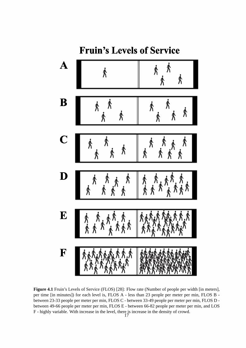
Figure 4.1Fruin’s Levels of Service (FLOS) [28]: Flow rate (Number of people per width [in meters],per time [in minutes]) for each level is, FLOS A - less than 23 people per meter per min, FLOS B -between 23-33 people per meter per min, FLOS C - between 33-49 people per meter per min, FLOS D -between 49-66 people per meter per min, FLOS E - between 66-82 people per meter per min, and LOSF - highly variable. With increase in the level, there is increase in the density ofcrowd.
17
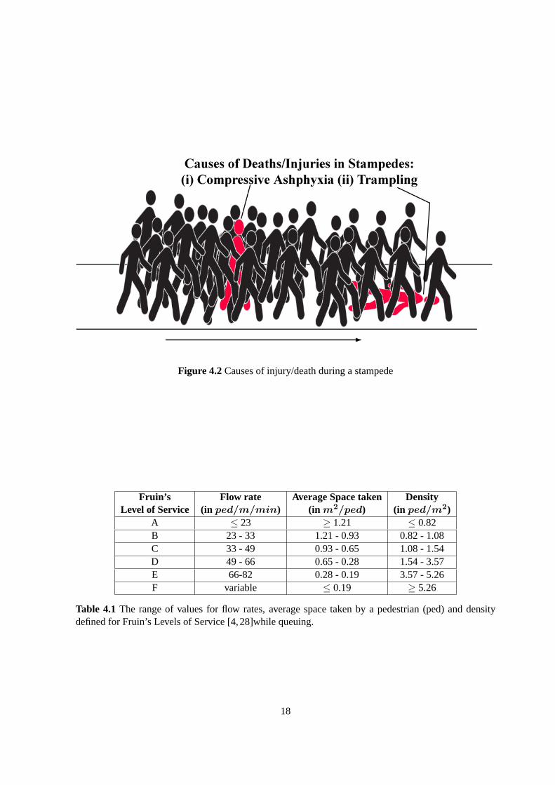
Figure 4.2Causes of injury/death during a stampede
Fruin’s Flow rate Average Space taken DensityLevel of Service (in ped/m/min) (in m2/ped) (in ped/m2)
A ≤ 23 ≥ 1.21 ≤ 0.82B 23 - 33 1.21 - 0.93 0.82 - 1.08C 33 - 49 0.93 - 0.65 1.08 - 1.54D 49 - 66 0.65 - 0.28 1.54 - 3.57E 66-82 0.28 - 0.19 3.57 - 5.26F variable ≤ 0.19 ≥ 5.26
Table 4.1 The range of values for flow rates, average space taken by a pedestrian (ped) and densitydefined for Fruin’s Levels of Service [4,28]while queuing.
18

States of Flow Rate Average Space taken DensityQueuing (in ped/m/min) (in m2/ped) (in ped/m2)
(i) Free Flow ≤ 49 ≥ 0.65 ≤ 1.54(ii) Constant Flow 49 - 66 0.65 - 0.28 1.54 - 3.57
(iii) Congestion Flow 66 - 82 0.28 - 0.19 3.57 - 5.26(iv) Stampede ≥ 82 (variable) ≤ 0.19 ≥ 5.26
Table 4.2 The range of values for flow rates, average space taken by a pedestrian (ped) and densitydefined for different states of queuing at temples.
crowd density less than 2 pedestrians per square meter, there is a free flow with people moving at their
maximum possible speeds. When the crowd density increases up to 4-5 pedestrians per square meter,
the situation is likely to build up congestion implying a risk for the occurrence of stampede. When
there are increased densities upto 6 (or more) pedestrians per square meter, there is high risk of shock
waves with people getting injured and crushed. Based on the flow rates defined by Fruin’s Levels of
Service while queuing (see Table 4.1) and Still’s analysis on crowd densities, four different states of
queuing are defined for the scenario of crowd management at temples: (i)Free flow (FLOS (A-C)),
(ii) Constant flow (FLOS (D)), (iii) Congestion flow (FLOS (E)) and (iv)Stampede (FLOS (F), see Ta-
ble 4.2). According to Hall [30], a person has regions around him known as intimate space (of radius
= 0.46 m and space = 0.67 sq.m) and personal space (> 0.67 sq.m) and he shows discomfort if this
space is intruded by other individuals. This explains that a person feels uncomfortable in a queue, as
his personal space is always intruded. And in the states of constant flowand congestion flow, his inti-
mate space is occupied which leads to anger and anxiety displayed by a person while moving in a queue.
4.1 States of the Queue at Temples and Calculation of Prayer time (δ)
At temples, the states of queuing vary depending not only on the rate of people entering the queue
(in-flow rateλ), but also on the rate at which people are exiting the queue (out-flow rateµ). The relation
between the in-flow rate (λ) and the out-flow rate (µ) for different states of queuing at temples is shown
in Figure 4.3 and the situation at temples in these states is explained in Table 4.3. The force experienced
by people in all these states are different. When the in-flow rate (λ) is increasing while the out-flow rate
(µ) is decreasing, the force (F ) exerted on agents increases, and the force exerted on people in the queue
decreases whenλ is decreasing whileµ is increasing (see Figure 4.4). The various states of simulation
of human agents queuing at temples are shown in the Figure 4.5.
The time allotted for people to spend (offering their prayers) inside the main temple arena (prayer
time δ), depends on the state of the queue determined. Thus, the prayer timeδ can be determined using
the in-flow (λ) and out-flow (µ) rates of a queue. Letδmax be the maximum possible amount of time
people can be allowed to stay in the main temple arena andδmin be the least (minimum) amount of time
19

Figure 4.3Various states of queuing at temples.
States of Queuing Relation betweenλ and µ Situation at Temples(i) Free Flow λ < µ When a very few people are visiting the tem-
ple, there would be no waiting, people tend tomove freely and can spend substantial amountof time in front of the deity to pray.
(ii) Constant Flow λ ≈ µ When there is gradual increase in flow rate,people tend to move slow, waiting time in-creases and any sort of congestion is likely toget initiated.
(iii) Congestion Flow λ > µ If flow rate of people leaving the queue is nothigher than the flow rate of people enteringthe queue, it causes congestion and crowd be-comes agitated exerting forces on each other.
(iv) Stampede λ >> µ The state of congestion flow when continuesto be in the same state, this might lead to astampede.
Table 4.3The situations that occur at temples for different states of queuing.
20
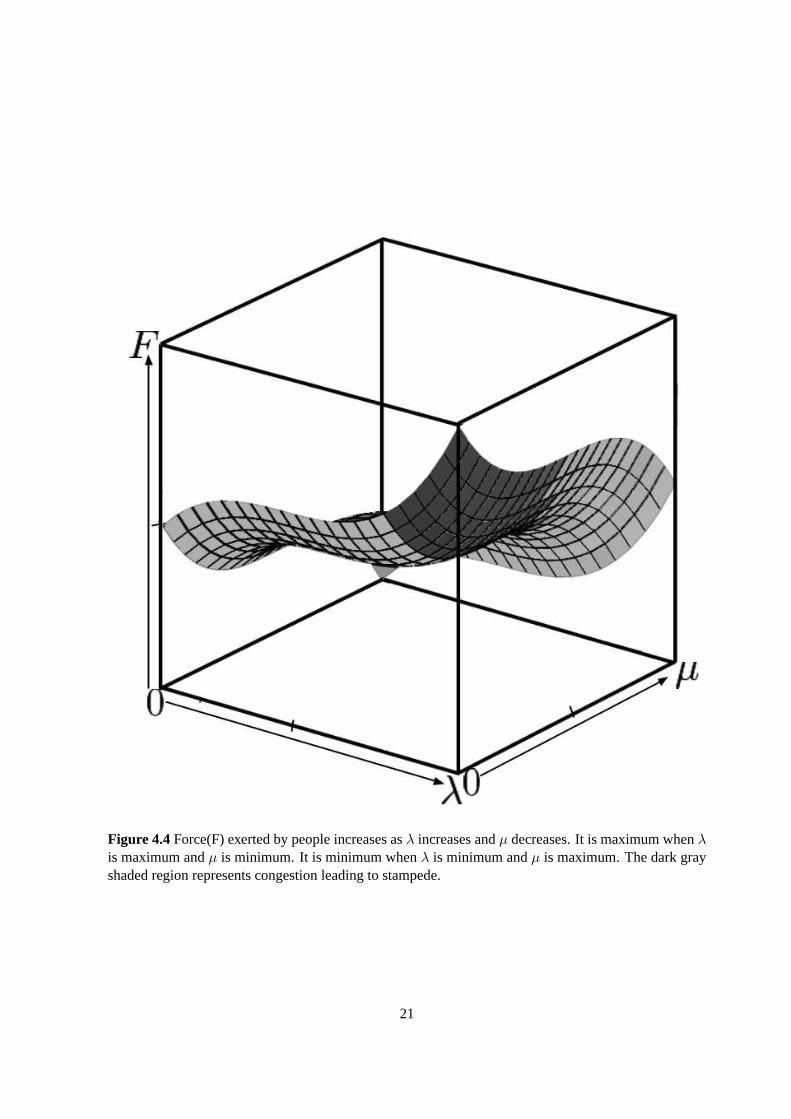
Figure 4.4Force(F) exerted by people increases asλ increases andµ decreases. It is maximum whenλis maximum andµ is minimum. It is minimum whenλ is minimum andµ is maximum. The dark grayshaded region represents congestion leading to stampede.
21

Figure 4.5 Various States of Queuing: (a) Free Flow, (b) Constant Flow, (c) Congestion Flow, and (d)Stampede.
22
that can allotted for people to offer their prayers.δmax andδmin are usually fixed for a temple and so in
a simulation run. When only few people are visiting the temple, there is a free flowin the queue, that is
people can be allowed to spend substantial amount of time inside the main temple arena (in front of a
deity) and thus, the prayer timeδ is set toδmax. And when the queue is highly congested, sinceδ cannot
be made negligible, it is set to the minimum time allottedδmin, so that people can offer their prayers.
The flow rate calculated at the entrance, that is, the number of people entering the queue per width (w,
width of the queue) per time step (τR) is the in-flow rate (λ) of the queue and the flow rate calculated
at the exit, that is, the number of people exiting the queue per width per time step isthe out-flow rate
(µ) of the queue. The time stepτR is equal to the calculated prayer timeδ, so that the flow rate values
are updated whenever a new set of people walk into the main temple arena. The prayer time (δ) cannot
exceed the maximum prayer time (δmax) and should be greater than the minimum prayer time (δmin).
Hence,
δ(λ, µ, δmin, δmax) = minimum{δmin +µ
λδmin , δmax} (4.1)
Here,λ andµ are the in-flow and out-flow rates of the queue. This equation shows that when there is
free flow, that is when the out-flow rate is greater than the in-flow rate (µ ¿λ), δ is high, but, does not
exceed the maximum alloted timeδmax. Even when there is congestion, that is when in-flow rate is
higher than the out-flow rate (λ ¿µ), δ is low, but greater than minimum possible timeδmin.
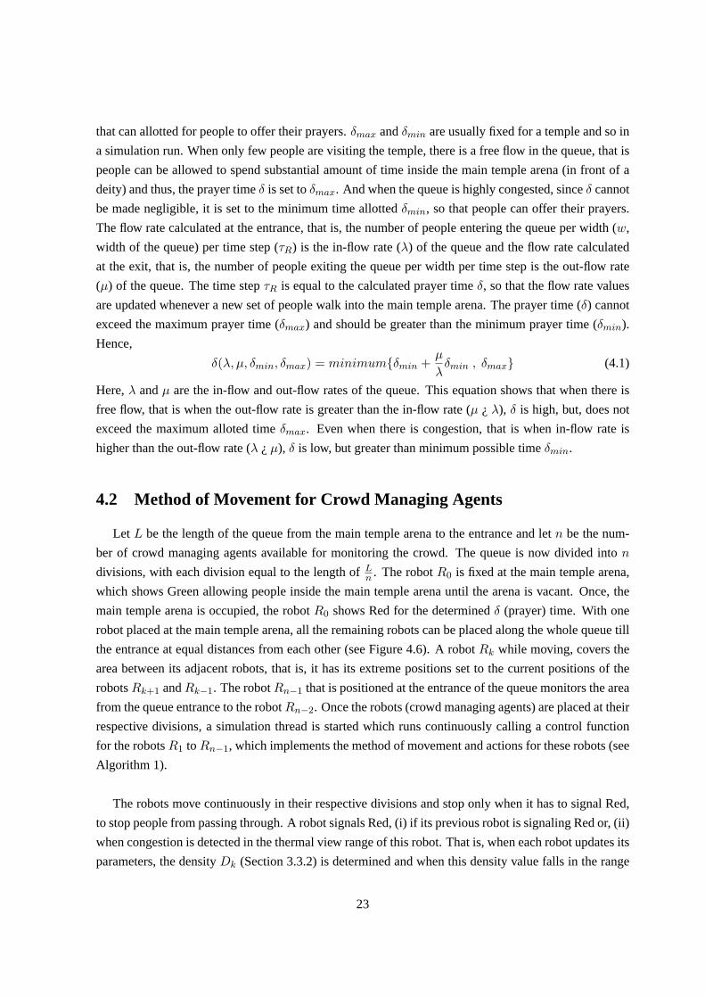
4.2 Method of Movement for Crowd Managing Agents
Let L be the length of the queue from the main temple arena to the entrance and letn be the num-
ber of crowd managing agents available for monitoring the crowd. The queue is now divided inton
divisions, with each division equal to the length ofLn
. The robotR0 is fixed at the main temple arena,
which shows Green allowing people inside the main temple arena until the arena isvacant. Once, the
main temple arena is occupied, the robotR0 shows Red for the determinedδ (prayer) time. With one
robot placed at the main temple arena, all the remaining robots can be placed along the whole queue till
the entrance at equal distances from each other (see Figure 4.6). A robotRk while moving, covers the
area between its adjacent robots, that is, it has its extreme positions set to thecurrent positions of the
robotsRk+1 andRk−1. The robotRn−1 that is positioned at the entrance of the queue monitors the area
from the queue entrance to the robotRn−2. Once the robots (crowd managing agents) are placed at their
respective divisions, a simulation thread is started which runs continuouslycalling a control function
for the robotsR1 toRn−1, which implements the method of movement and actions for these robots (see
Algorithm 1).
The robots move continuously in their respective divisions and stop only when it has to signal Red,
to stop people from passing through. A robot signals Red, (i) if its previous robot is signaling Red or, (ii)
when congestion is detected in the thermal view range of this robot. That is, when each robot updates its
parameters, the densityDk (Section 3.3.2) is determined and when this density value falls in the range
23

Figure 4.6Robot are numbered starting from the main temple arena to the queue entrance. R0 is placedat the entrance of main temple arena andRn−1 is placed at the entrance of the queue.
of densities for a congestion flow (Table 4.2 - (iii)), the robot is said to havedetected a congested area.
The robot then shows Red stopping people from entering the already congested region.
4.3 Results
The results of multi-agent simulation for the temple scenario with human agents in a long queue are
presented in this section. A series of actions performed by the crowd managing agents (robots using
the method of movement described above and determined prayer timeδ to manage the crowd), are pre-
sented in the Figure 4.7.
Figure 4.7(a) shows the robots being initially introduced and placed at equal distances signaling
Green to allow people to pass through. A robotRk (here,k=1-6), moves between its adjacent robots.
Figure 4.7(b) shows that the robotR3 detects congestion in its thermal detection range and hence
signals Red until the congestion is cleared. The robotsR4, R5, andR6, signal Red as their previous
robots (R3, R4 andR5 respectively) are currently showing Red.
Once the congestion is cleared at the robotR3, it shows Green and the robotsR4,R5 andR6 showing
Red in Figure 4.7(c) are updated to signal Green as shown in Figure 4.7(d). In Figure 4.7(d), the robot
R0 shows Red as the main temple arena is not vacant.
In Figure 4.7(e), the robotR5 detects congestion and signals Red, followed by the robotR6 signaling
Red.
Table 4.4 shows states of the queue determined for certain in-flow rateλ and out-flow rateµ values
and the prayer timeδ allotted during these states.
24

Algorithm 1 Algorithm followed by Crowd managing robotic agents to detect and reduce congestion
procedure INIT ROBOT( Robot r, Pos startPos ) ⊲ All robot are initialized
r.setCurrPosition = startPos;r.setSignal(Green);r.setMoveForward();τR = curr δ; ⊲ Timestep after whichλ andµ are updated
end procedure————————procedure MOVEMENTFUNC( Robot r ) ⊲ This update is called after each simulation stepτH
r.setStartPosition = r.nextRobot().currPosition; ⊲ A robot moves in between its adjacent robots
r.setEndPosition = r.prevRobot().currPosition;r.D = r.PC/(w ∗ l); ⊲ Density in the rectangular detection range
if getRobotAt(r.nextPos()) then ⊲ Robots moves between its adjacent robots
if r.isSetForward() thenr.setBackward();
elser.setForward();
end ifend ifif r.isSetForward() then ⊲ Move in the direction of the flow towards its previous robot
r.moveStepForward();else ifr.issetBackward() then ⊲ Movie in the opposite direction of the flow towards its next robot
r.moveStepBackward();else
r.stopMove();end ifif r.prevRobot().isRed() then
r.setSignal(Red);r.stopMove();
else ifisCongested(r.D) then ⊲ Detects congestion caused due to high density
r.setSignal(Red);r.stopMove();
elser.setSignal(Green);
end ifend procedure————————procedure UPDATEFUNC( Robot r ) ⊲ This function is called each variable robot time stepτR
λ = curr λ;µ = curr µ;curr δ = getCurrPrayerT ime(λ, µ);τR = curr δ;
end procedure
25
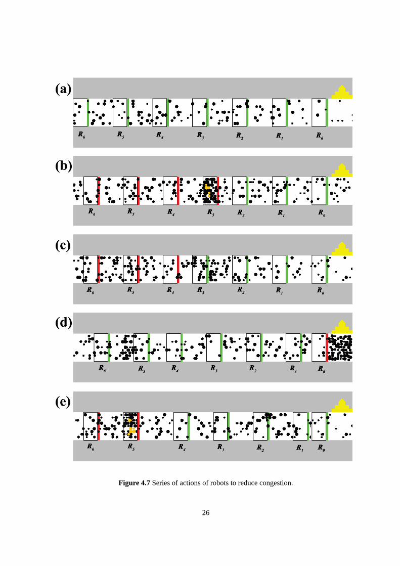
Figure 4.7Series of actions of robots to reduce congestion.
26
In-flow rate(λ) Out-flow rate(µ) State of the Prayer time(δ)(in ped/m/min) (in ped/m/min) Queue (in seconds)
12 38 Free Flow 428 42 Free Flow 5049 58 Constant Flow 2265 32 Congestion Flow 1572 20 Stampede Flow 13
Table 4.4Prayer timeδ determined using in-flow and out-flow rates. Here,δmin=10s andδmax=50s.
Figure 4.8 The state of the queue would be determined as congestion flow, but not all the areas of thequeue are congested.
4.4 Discussion
In this method, when a robot detects congestion in its thermal view range, it shows red signal stop-
ping the people from further congesting the area. This action is followed byall the robots (next to the
robot that detected congestion) signaling Red. This stops people from passing these robots and hence
preventing the possibility of congestion. This may achieve a stampede free flow of people, but it is
not efficient. This method of movement keeps people waiting, when instead they could be allowed to
move until before they reach the congested area. Also in this method, the robots move continuously to
monitor the crowd and detect any congested areas. This is not necessary unless there are any congested
areas for the robot to detect or unless the crowd in an area that is being monitored by the robot, needs
management.
The robot that is at the main temple arena acts according to the calculated prayer time (δ). It signals
Red when the main temple arena is occupied and releases people inside the main temple arena afterδ
time and allows new set of people inside. The above results in Table 4.4, showthat people get to spend
time greater than minimum time allotted for their prayers. The prayer time and the statesof the queue
are determined using the in-flow rateλ at the entrance and the out-flow rateµ at the exit. But the queue
being very long, the states interpreted just by the calculating values ofλ andµ may not be valid. There
could be intermediate state changes in the queue. For example, in Figure 4.8, the state of the queue
determined would be constant flow or congestion flow as the people are entering the queue at a higher
27

rate than people exiting the queue. But, there is a part of the queue in between which contains a few
people moving with no forces being exerted on them (free flow of people).This part of the queue does
not need any crowd management and the people in this area could be allowedfor a longer duration to
pray. This would not happen if the prayer timeδ is determined using the flow rates at entranceλ and
exit µ. Similarly, there can be a congested area in between when the state of the queue is interpreted as
free flow. And hence, the praying time and the state of the queue determined are not appropriate.
Hence, the method of movement as well as the perspective of interpreting various states of the queue
and determining the prayer time should be modified to achieve better efficiency incrowd management.
In the next chapter, we improve these methods.
28

Chapter 5
An Extended Method of Movement for Crowd
Managing Agents
As discussed in Chapter 4, determining the state of the long queue based on the rates of people en-
tering and exiting the queue may not be valid and the method of movement of robots is not efficient.
In this chapter we present a different perspective to determine variousstates of queuing and to calcu-
late prayer time, and extend the method of movement described in Chapter 4 to improve efficiency in
management such that people get enough time to offer their prayers. The actions of robots unlike in the
method described earlier, are independent, that is a robot does not takean action considering the actions
performed by its adjacent robots.
Let each crowd managing agent determine a flow rate (λk), that is the number of people crossing
the robotRk per width (w, width of the queue) per time step (τR). If λk is the rate at which people
are entering the area between the robotsRk and robotRk−1 , and hence the flow rate of people exiting
this area would be the flow rate (λk−1) determined by the robotRk−1. That is, for the area (part of the
queue) between the robotsRk andRk−1 the rate of people entering (in-flow rate) isλk and the rate at
which the people are exiting (out-flow rate) isµk = λk−1. Thus, the long queue of human agents is
divided into small individual queues and each queue is independently managed by the robots achieving
an overall stampede free flow in the long queue. The time stepτR is equal to the prayer timeδ, so
that all the robots update their flow rate values whenever a new set of people walk into the main temple
arena. The prayer timeδ is determined based on the in-flow (λ) and out-flow (µ) rates of a queue. Since
the people flowing from the robotsR1 toR0 will next enter the main temple arena (once it is clear), the
flow rates determined at these robots are considered to calculate the prayer time. The prayer time cannot
exceed the maximum prayer time (δmax) and should be greater than the minimum prayer time (δmin).
δ(λ1, µ1, δmin, δmax) = minimum{δmin +µ1
λ1
δmin , δmax} (5.1)
Here,λ1 andµ1 (= λ0) are the in-flow and out-flow rates of the queue between the robotsR1 andR0.
29
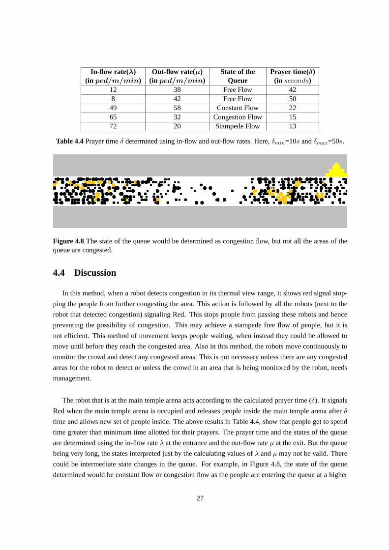
Figure 5.1Various states of a queue between two robotsRk andRk−1
5.1 A Different Perspective of determining Various States of Queuing
Consider the part of the long queue between the current positions of robots Rk andRk−1 as an
individual queue that is managed by the robotRk. Various states of an individual queue are defined
based on the relation betweenλk andµk, the in-flow and out-flow rates of people in the queue flowing
from Rk to Rk−1 (see Table 5.1 and Figure 5.1). The range of values ofλk andµk defined for the
states of an individual queue are with respect to the range of flow rates defined for the different states of
queuing at temples (Table 4.2).
• Free Flow: Whenλk << µk, there are very few people passing through the robotRk and the
in-flow rate of people is significantly less than the out-flow rate of people.
States of an individual Queue betweenRk andRk−1
Relation between λk and µk(= λk−1) in(ped/m/min)
Free Flow 0 < λk << µk < 49
Constant Flow 49 < λk ≈ µk < 66, |λk − µk| → 0
Congestion Flow 66 < µk < λk << 82
Stampede Flow 66 < µk << λk < 82, 66 < µk << 82 < λk
Table 5.1The states of an individual queue betweenRk andRk−1 are determined using the in-flow rate(λk) and out-flow rate (µk) of people.
30
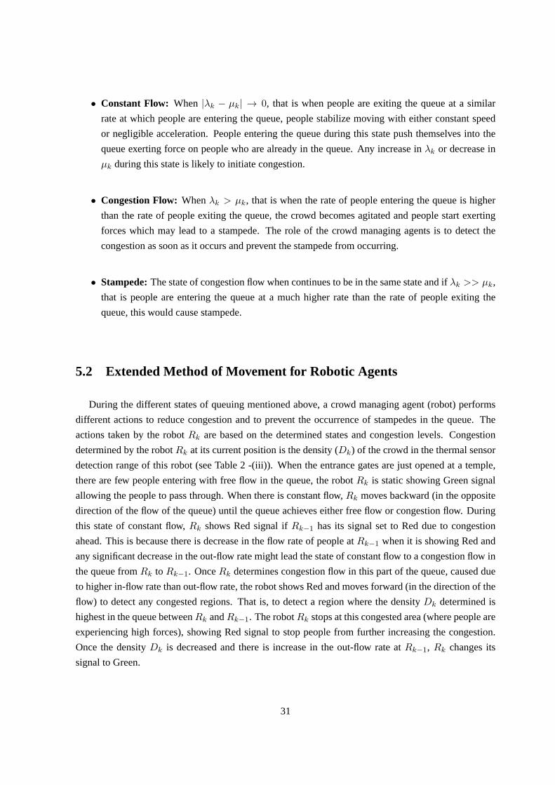
• Constant Flow: When |λk − µk| → 0, that is when people are exiting the queue at a similar
rate at which people are entering the queue, people stabilize moving with eitherconstant speed
or negligible acceleration. People entering the queue during this state push themselves into the
queue exerting force on people who are already in the queue. Any increase inλk or decrease in
µk during this state is likely to initiate congestion.
• Congestion Flow: Whenλk > µk, that is when the rate of people entering the queue is higher
than the rate of people exiting the queue, the crowd becomes agitated and people start exerting
forces which may lead to a stampede. The role of the crowd managing agents isto detect the
congestion as soon as it occurs and prevent the stampede from occurring.
• Stampede:The state of congestion flow when continues to be in the same state and ifλk >> µk,
that is people are entering the queue at a much higher rate than the rate of people exiting the
queue, this would cause stampede.
5.2 Extended Method of Movement for Robotic Agents
During the different states of queuing mentioned above, a crowd managingagent (robot) performs
different actions to reduce congestion and to prevent the occurrenceof stampedes in the queue. The
actions taken by the robotRk are based on the determined states and congestion levels. Congestion
determined by the robotRk at its current position is the density (Dk) of the crowd in the thermal sensor
detection range of this robot (see Table 2 -(iii)). When the entrance gatesare just opened at a temple,
there are few people entering with free flow in the queue, the robotRk is static showing Green signal
allowing the people to pass through. When there is constant flow,Rk moves backward (in the opposite
direction of the flow of the queue) until the queue achieves either free flowor congestion flow. During
this state of constant flow,Rk shows Red signal ifRk−1 has its signal set to Red due to congestion
ahead. This is because there is decrease in the flow rate of people atRk−1 when it is showing Red and
any significant decrease in the out-flow rate might lead the state of constantflow to a congestion flow in
the queue fromRk to Rk−1. OnceRk determines congestion flow in this part of the queue, caused due
to higher in-flow rate than out-flow rate, the robot shows Red and moves forward (in the direction of the
flow) to detect any congested regions. That is, to detect a region wherethe densityDk determined is
highest in the queue betweenRk andRk−1. The robotRk stops at this congested area (where people are
experiencing high forces), showing Red signal to stop people from further increasing the congestion.
Once the densityDk is decreased and there is increase in the out-flow rate atRk−1, Rk changes its
signal to Green.
31
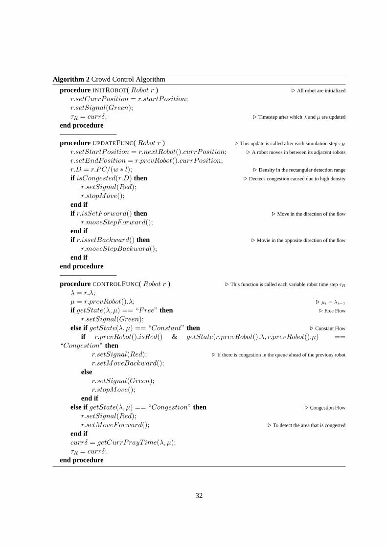
Algorithm 2 Crowd Control Algorithm
procedure INIT ROBOT( Robot r ) ⊲ All robot are initialized
r.setCurrPosition = r.startPosition;r.setSignal(Green);τR = currδ; ⊲ Timestep after whichλ andµ are updated
end procedure————————procedure UPDATEFUNC( Robot r ) ⊲ This update is called after each simulation stepτH
r.setStartPosition = r.nextRobot().currPosition; ⊲ A robot moves in between its adjacent robots
r.setEndPosition = r.prevRobot().currPosition;r.D = r.PC/(w ∗ l); ⊲ Density in the rectangular detection range
if isCongested(r.D) then ⊲ Dectecs congestion caused due to high density
r.setSignal(Red);r.stopMove();
end ifif r.isSetForward() then ⊲ Move in the direction of the flow
r.moveStepForward();end ifif r.issetBackward() then ⊲ Movie in the opposite direction of the flow
r.moveStepBackward();end if
end procedure————————procedure CONTROLFUNC( Robot r ) ⊲ This function is called each variable robot time stepτR
λ = r.λ;µ = r.prevRobot().λ; ⊲ µi = λi−1
if getState(λ, µ) == “Free” then ⊲ Free Flow
r.setSignal(Green);else ifgetState(λ, µ) == “Constant” then ⊲ Constant Flow
if r.prevRobot().isRed() & getState(r.prevRobot().λ, r.prevRobot().µ) ==“Congestion” then
r.setSignal(Red); ⊲ If there is congestion in the queue ahead of the previous robot
r.setMoveBackward();else
r.setSignal(Green);r.stopMove();
end ifelse ifgetState(λ, µ) == “Congestion” then ⊲ Congestion Flow
r.setSignal(Red);r.setMoveForward(); ⊲ To detect the area that is congested
end ifcurrδ = getCurrPrayT ime(λ, µ);τR = currδ;
end procedure
32
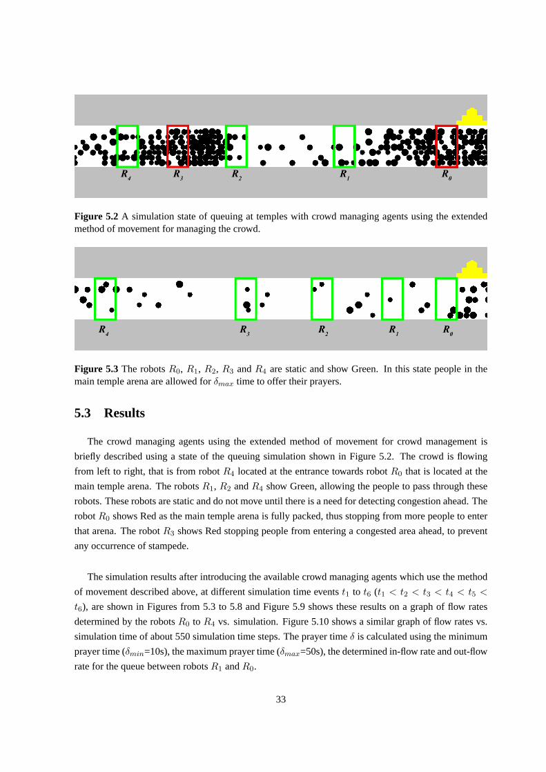
Figure 5.2 A simulation state of queuing at temples with crowd managing agents using the extendedmethod of movement for managing the crowd.
Figure 5.3 The robotsR0, R1, R2, R3 andR4 are static and show Green. In this state people in themain temple arena are allowed forδmax time to offer their prayers.
5.3 Results
The crowd managing agents using the extended method of movement for crowd management is
briefly described using a state of the queuing simulation shown in Figure 5.2. The crowd is flowing
from left to right, that is from robotR4 located at the entrance towards robotR0 that is located at the
main temple arena. The robotsR1, R2 andR4 show Green, allowing the people to pass through these
robots. These robots are static and do not move until there is a need for detecting congestion ahead. The
robotR0 shows Red as the main temple arena is fully packed, thus stopping from more people to enter
that arena. The robotR3 shows Red stopping people from entering a congested area ahead, to prevent
any occurrence of stampede.
The simulation results after introducing the available crowd managing agents which use the method
of movement described above, at different simulation time eventst1 to t6 (t1 < t2 < t3 < t4 < t5 <
t6), are shown in Figures from 5.3 to 5.8 and Figure 5.9 shows these results on a graph of flow rates
determined by the robotsR0 to R4 vs. simulation. Figure 5.10 shows a similar graph of flow rates vs.
simulation time of about 550 simulation time steps. The prayer timeδ is calculated using the minimum
prayer time (δmin=10s), the maximum prayer time (δmax=50s), the determined in-flow rate and out-flow
rate for the queue between robotsR1 andR0.
33

Figure 5.4 This shows that the main temple arena is full and the robotR0 shows Red for aδmax
time. As there is increase in the flow rate (people entering per minute), people entering in this state areaccumulated at robotR0 until they are allowed into the main temple arena for prayers.
Figure 5.5Since people are accumulating at the robotR0, the robotR1 moves towards the main templearena to control the crowd accumulating. Once the robotR1 detects congestion in an area, it stops andshows Red stopping people from accumulating further.
Figure 5.6The main temple arena is now vacant that the robotR0 shows Green allowing people (whowere earlier accumulating atR0) to enter until the main temple arena is full. The robotR1 is Red as theflow rate at robotR0 is not high to reduce the congestion ahead ofR1.
34

Figure 5.7When the flow rate increases at the entrance, the rate of people passing the robotR4 is higherthan the rate of people passing the robotR3, and people entering the queue push themselves exertingforces on people already in the queue. In this case, the robotR4 shows Red stopping people frompassing through, there by reducing the forces experienced by peoplethat have already passedR4 untilthe flow rate atR3 is higher than the flow rate atR4 and congestion is reduced.
Figure 5.8 This shows a situation where there is free flow of people from robotsR4 to R1 andR1 ismoving towardsR0 to detect any congested areas, as there are people accumulating atR0. And R0 isshowing Red as the main temple arena is not vacant.
35

Figure 5.9The graphs of flow rate (λ) vs simulation time (t) for the robotsR0,R1,R2,R3 andR4 usingthe method of movement (Algorithm 1). The robotR0 shows Red forδ time when the main temple arenais occupied. The Red and Green dots on a graph show the changes in the signal of the correspondingrobot. The prayer timeδ for which the robotR0 shows Red, is calculated using the in-flow rateR1.λ,out-flow rateR0.µ, δmin andδmax. Hereδmin=10s andδmax=50s.
36

Figure 5.10The graphs of flow rate (λ) vs simulation time (t) for the robotsR0, R1, R2, R3 andR4
using the method of movement (Algorithm 1) for about 550 simulation time steps. This graph showsthat the robotR2 remained idle during this simulation run. Hereδmin=10s andδmax=50s.
37

5.4 Discussion
Unlike the method of movement described in Chapter 4, in this method, the robots donot move
continuously to detect any congested areas. Now that the states of individual queues between the robots
are determined using flow rates calculated by each robot, a robot moves only when the part of the queue
between itself and its previous robot seem to approach a congestion state.Figure 5.2 shows that the
robotR4 shows Green, as there is no congestion detected between itself and robotR3. That is, a robot’s
action is independent of the adjacent robots and a robot shows Red to stop people if and only if there is
congestion detected at this robot. The prayer time is determined based on the in-flow and out-flow rates
of the individual queue that is next to the main temple arena. Hence, the valueof δ is appropriate with
the state determined for this individual queue and is higher than minimum amount of time (δ) allotted
for the people to offer their prayers.
These results (Figure 5.3 to 5.8), show that the robotsR2 andR3 were always signaling Green
during the simulation (allowing people to pass through), which if removed, would not have effected the
movement of the human agents. Similarly, the graph shown in Figure 5.10 showsthat the robotR2
remained same showing Green signal through out the simulation. That is, the number of robots used is
higher than the required number of robots. Using robots more than the required number at any point of
the time during the simulation, may result in some robots being idle for major time intervals of queuing.
Situations may occur where the robots currently monitoring the queue are notsufficient to manage all
the congested parts of the queue. That is, the number of robots used would be less than the required
number of robots. Hence, we provide a method in the next chapter that uses only required number of
robots to manage the long queue.
38

Chapter 6
Required Number of Crowd Managing Robotic
Agents
The method discussed in the previous chapter uses a number of crowd managing agents (robots)
which may be is more or less than the actual number of robots required to manage the queue at a given
time. If n is the number of robots available, not all then robots would be necessary to manage the
crowd at different states of queuing. For example, when entrance of the queue is opened or when there
are very few people visiting the temple, we do not require alln robots to manage the queue, instead two
robots can be used, one at the entrance and the other at the main temple arena until congestion is likely
to occur. When congestion occurs the other robots are called as and when necessary.
6.1 Using a Required Number of Crowd Managing Agents
Sayl is the number of robots required to manage the queue at a timet, such that2 ≤ l ≤ n. The
number of robots in the queue at timet is the number of robots required (necessary) to manage the
crowd, if people do not get injured and stampedes do not occur, even when the queue is packed with
people exerting forces on each other. Thesel required number of robots manage the queue such that,
the congestion is reduced and stampedes are avoided (see Algorithm 3).
A robot is always placed at the main temple arena, which ensures that people entering the temple
arena get enough time (the calculated value of prayer timeδ) to pray. And when the queue starts in
addition to the robot placed at the main temple arena, another robot is placed at the entrance of the
long queue. Any robot that is placed at the entrance moves towards awayfrom the entrance when the
crowd starts accumulating at the previous robot. When it starts moving from the queue entrance, it
moves until it finds an area where there is a set of packed people which is likely to get congested (this is
determined using the densityDk). If a robotRk moving between the robotsRk+1 andRk−1, determines
39

Algorithm 3 Algorithm for Required Number of CMAs
procedure INIT() ⊲ When the temples gates are just opened
Robot rE = newRobot();rE.setToTempleArenaPos(); ⊲ This robot placed at the main temple arena
rE.manageMainTempleArena(); ⊲ This ensures that people inside main temple arena getδ time to offer their
prayers
Robot rS = newRobot();addRobotAtEntrance(rS); ⊲ A new robot starts from the entrance of the queue
end procedure——————–procedure ADDROBOTATENTRANCE(Robot r)
if isCrowdAccumulating(r.prevRobot()) thenr.setMoveForward();r.startControlThread(); ⊲ In addition to the steps inside the control function of Algorithm 1, checkRequired(r)
step is added.
end ifend procedure——————–procedure CHECKREQUIRED(Robot r) ⊲ This function checks if there are more or less number of robots than required in
the queue fromRk+1 toRk−1 for a robotRk
if isLessThanRequired(r) then ⊲ Checks if there are more than one congested areas with high densities
addRobotAtEntrance(newRobot());else ifisMoreThanRequired(r) then ⊲ Checks if there are no congested areas
Robot rTemp = rwhile rTemp.nextRobot() do
rTemp.setCurrPosition(rTemp.nextRobot().currPosition);rTemp = rTemp.nextRobot()
end whileremoveRobotAtEntrance();
end ifend procedure
40
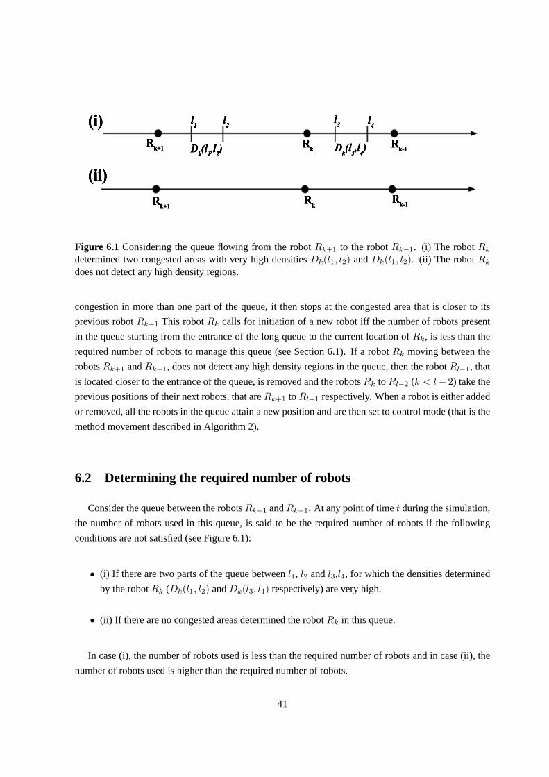
Figure 6.1 Considering the queue flowing from the robotRk+1 to the robotRk−1. (i) The robotRk
determined two congested areas with very high densitiesDk(l1, l2) andDk(l1, l2). (ii) The robotRk
does not detect any high density regions.
congestion in more than one part of the queue, it then stops at the congested area that is closer to its
previous robotRk−1 This robotRk calls for initiation of a new robot iff the number of robots present
in the queue starting from the entrance of the long queue to the current location of Rk, is less than the
required number of robots to manage this queue (see Section 6.1). If a robot Rk moving between the
robotsRk+1 andRk−1, does not detect any high density regions in the queue, then the robotRl−1, that
is located closer to the entrance of the queue, is removed and the robotsRk toRl−2 (k < l− 2) take the
previous positions of their next robots, that areRk+1 toRl−1 respectively. When a robot is either added
or removed, all the robots in the queue attain a new position and are then set tocontrol mode (that is the
method movement described in Algorithm 2).
6.2 Determining the required number of robots
Consider the queue between the robotsRk+1 andRk−1. At any point of timet during the simulation,
the number of robots used in this queue, is said to be the required number of robots if the following
conditions are not satisfied (see Figure 6.1):
• (i) If there are two parts of the queue betweenl1, l2 andl3,l4, for which the densities determined
by the robotRk (Dk(l1, l2) andDk(l3, l4) respectively) are very high.
• (ii) If there are no congested areas determined the robotRk in this queue.
In case (i), the number of robots used is less than the required number of robots and in case (ii), the
number of robots used is higher than the required number of robots.
41
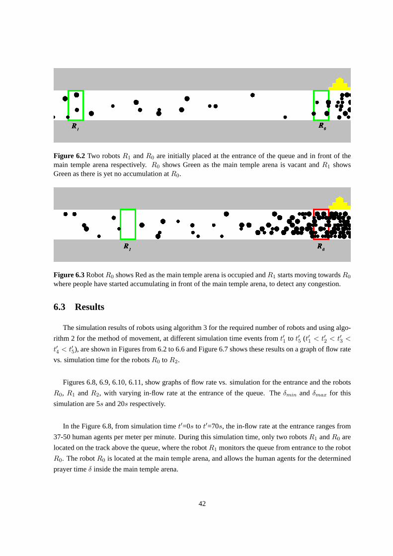
Figure 6.2 Two robotsR1 andR0 are initially placed at the entrance of the queue and in front of themain temple arena respectively.R0 shows Green as the main temple arena is vacant andR1 showsGreen as there is yet no accumulation atR0.
Figure 6.3RobotR0 shows Red as the main temple arena is occupied andR1 starts moving towardsR0
where people have started accumulating in front of the main temple arena, to detect any congestion.
6.3 Results
The simulation results of robots using algorithm 3 for the required number of robots and using algo-
rithm 2 for the method of movement, at different simulation time events fromt′1 to t′5 (t′1 < t′2 < t′3 <
t′4 < t′5), are shown in Figures from 6.2 to 6.6 and Figure 6.7 shows these results on a graph of flow rate
vs. simulation time for the robotsR0 toR2.
Figures 6.8, 6.9, 6.10, 6.11, show graphs of flow rate vs. simulation for theentrance and the robots
R0, R1 andR2, with varying in-flow rate at the entrance of the queue. Theδmin andδmax for this
simulation are 5s and 20s respectively.
In the Figure 6.8, from simulation timet′=0s to t′=70s, the in-flow rate at the entrance ranges from
37-50 human agents per meter per minute. During this simulation time, only two robotsR1 andR0 are
located on the track above the queue, where the robotR1 monitors the queue from entrance to the robot
R0. The robotR0 is located at the main temple arena, and allows the human agents for the determined
prayer timeδ inside the main temple arena.
42

Figure 6.4 OnceR1 detects congestion, it stops and shows Red. This is when it calls for a new robot(R2) that is placed at the entrance.
Figure 6.5 The number of people entering the queue increased suddenly at the entrance and the robotR2 detects a congestion state based on the flow rate determined. It moves towardsR1 and shows Redwhen it detects any congested area. A new robot is not called as the robot R2 detects only one regionthat is highly congested.
Figure 6.6The robotR2 is removed as the robotR1 does not detect any congested areas andR1 takesthe previous position ofR2. The robotR1 shows green as there is not yet any accumulation at the robotR0.
43

Figure 6.7 The graphs of flow rate (λ) vs simulation time (t′) for the robotsR0, R1 andR2 using themethod described in Algorithm 2 for moving and using the method described in Algorithm 3 to add orremove a robot. Here, the robotR2 is called at a later stage.
44

In the Figure 6.9, fromt′=70s to t′=90s, the in-flow rate suddenly increases upto 85 human agents
per meter per minute. Att′=81s, the robotR1 shows Red when it detects a congestion flow, which is
when another robotR2 is added at the entrance. Now,R2 monitors the queue from entrance to the robot
R1, whileR1 monitors the queue from robotR2 to robotR0.
In the Figure 6.10, fromt′=110s to t′=135s, the in-flow rate increases upto 68 human agents per me-
ter per minute and fromt′=140s to t′=220s, the in-flow rate is very low, and ranges from (0-10) human
agents per meter per minute. The robotR1, shows red att′=135s when it detects a higher density human
agents crowd and remains idle fromt′=156s to t′=214s detecting no congestion in the queue from robot
R2 to robotR0. Hence, the robotR1 is removed att′=214s.
In the Figure 6.11, fromt′=220s to t′=270s, there is no in-flow rate at the entrance and the human
agents already in the queue, experience no congestion and get to spendmaximum amount of time in
front of the deity inside the main temple arena. The prayer timeδ determined is closer toδmax. Once
the robotR1 was removed earlier, the robotR2 replacesR1, which monitors the queue from entrance to
robotR0 (or main temple arena).
Figure 6.12 combines the graphs from 6.8 to 6.11 showing a graph of flow rates determined by the
robotsR0 to R2 vs. simulation time of about 300 simulation time steps.
6.4 Discussion
The algorithm discussed in this chapter ensures that only required numberof crowd managing agents
are monitoring the queue while these crowd managing agents use the method of movement described in
Algorithm 2 (Chapter 5). The above results show that robots are being added or removed if necessary.
And the robots that remain in the queue adapt to their positions and continue to follow their methods.
This not only reduces the number of robots used at times, but only makes it easy to replace a robot when
needed, which would not be the case if all the available robots are put to use in managing the queue.
In the simulation graph shown in the Figure 6.12, the prayer time allotted for people to on an average
is δavg=11.7s. That is, people get to spend time greater than the minimum prayer timeδmin. If there
are no robots monitoring the queue, people would move until main temple arena exerting forces on each
other, which may or may not lead to a severe stampede, but, there would be congested areas with high
density crowds, that only the minimum prayer timeδmin is allotted for people to offer their prayers in
front the deity in the main temple arena. Hence, MAMAC (Multi-agent management of crowd) not only
avoids the occurrence of stampedes, but allows the people to spend substantial amount of time at their
destinations.
45
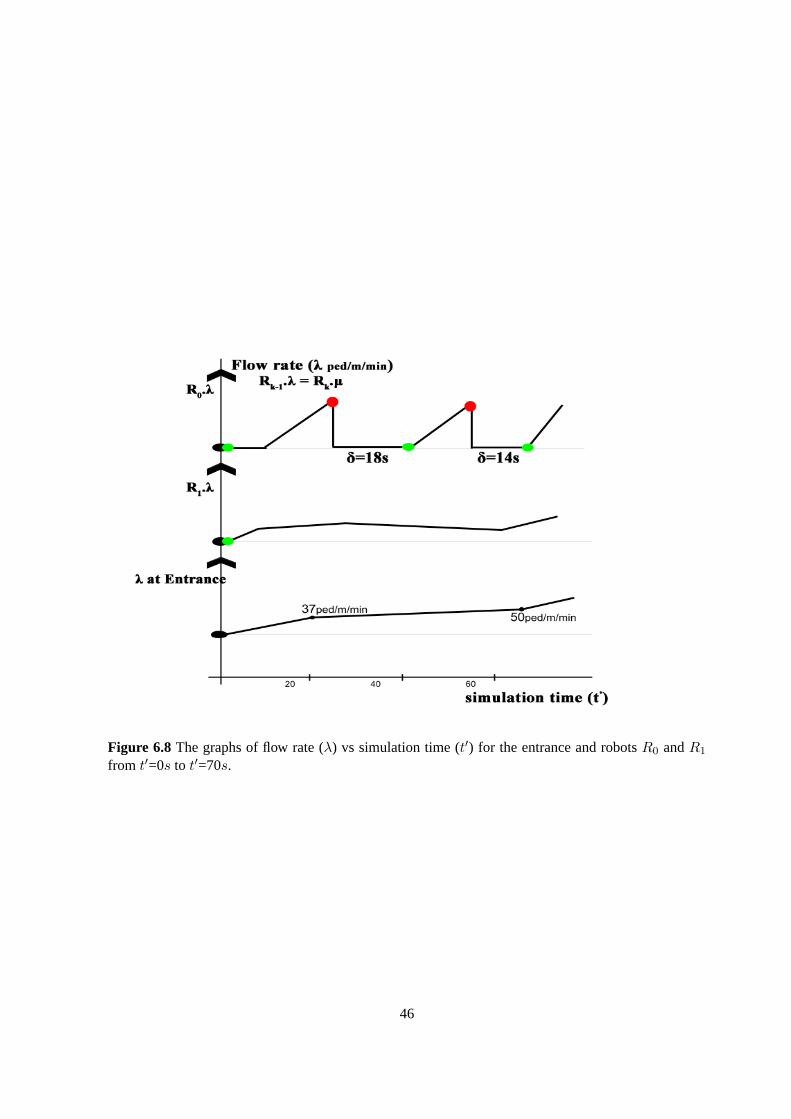
Figure 6.8 The graphs of flow rate (λ) vs simulation time (t′) for the entrance and robotsR0 andR1
from t′=0s to t′=70s.
46
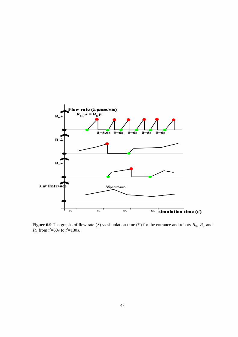
Figure 6.9 The graphs of flow rate (λ) vs simulation time (t′) for the entrance and robotsR0, R1 andR2 from t′=60s to t′=130s.
47

Figure 6.10The graphs of flow rate (λ) vs simulation time (t′) for the entrance and robotsR0, R1 andR2 from t′=120s to t′=220s.
48
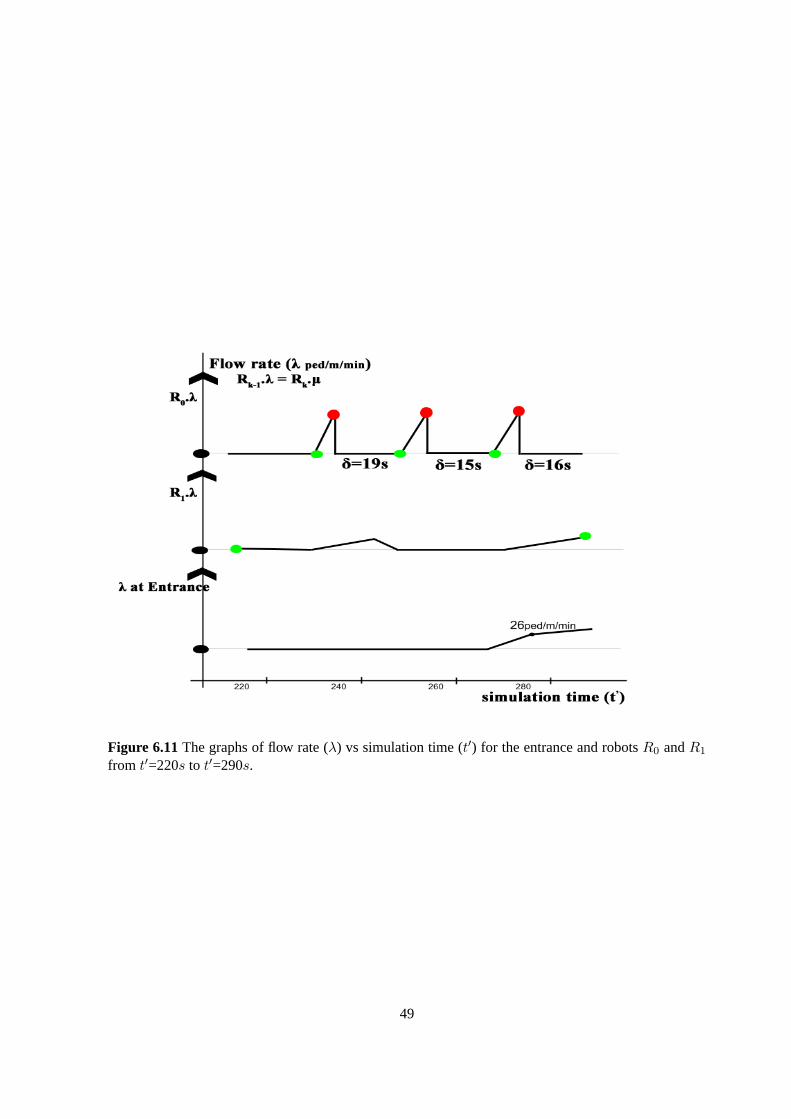
Figure 6.11The graphs of flow rate (λ) vs simulation time (t′) for the entrance and robotsR0 andR1
from t′=220s to t′=290s.
49

Figure 6.12The graphs of flow rate (λ) for the robotsR0, R1 andR2 vs. simulation time (t′) of about300 simulation time steps. The robotR2 is added to the track at time stept′=81s. The robotR1 isremoved at time stept′=214s there by monitoring the area from entrance of the queue to the maintemple arena.
50
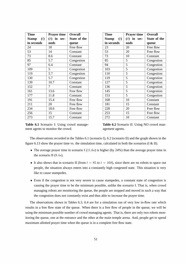
TimeStamp (t)in seconds
Prayer time(δ) in sec-onds
OverallState of thequeue
24 18 Free flow53 14 Constant73 8.6 Constant85 5.7 Congestion97 6.4 Constant109 5 Congestion119 5.7 Congestion130 5.7 Congestion139 10.7 Constant152 7 Constant161 13.6 Free flow177 11.8 Constant191 15.4 Free flow211 20 Free flow234 18.6 Free flow256 15 Constant273 15.7 Constant
Table 6.1 Scenario I: Using crowd manage-ment agents to monitor the crowd.
TimeStamp (t)in seconds
Prayer time(δ) in sec-onds
OverallState of thequeue
23 20 Free flow53 20 Free flow73 10 Constant85 5 Congestion94 5 Congestion103 5 Congestion110 5 Congestion119 5 Congestion127 5 Congestion136 5 Congestion145 5 Congestion153 5 Congestion168 10 Constant181 15 Constant228 20 Free flow253 15 Free flow272 10 Constant
Table 6.2Scenario II: Using NO crowd man-agement agents.
The observations recorded in the Tables 6.1 (scenario I), 6.2 (scenario II) and the graph shown in the
figure 6.13 show the prayer time vs. the simulation time, calculated in both the scenarios (I & II).
• The average prayer time in scenario I (11.6s) is higher (by 24%) than the average prayer time in
the scenario II (9.4s).
• It also shows that in scenario II (fromt = 85 to t = 168), since there are no robots to space out
people, the situation always enters into a constantly high congested state. This situation is very
like to cause stampedes.
• Even if the congestion is not very severe to cause stampedes, a constantstate of congestion is
causing the prayer time to be the minimum possible, unlike the scenario I. That is,when crowd
managing robots are monitoring the queue, the people are stopped and movedin such a way that
the congestion does not constantly exist and thus able to increase the prayer time.
The observations shown in Tables 6.3, 6.4 are for a simulation run of very low in-flow rate which
results in a free flow state of the queue. When there is a free flow of peoplein the queue, we will be
using the minimum possible number of crowd managing agents. That is, there are only two robots mon-
itoring the queue, one at the entrance and the other at the main temple arena. And, people get to spend
maximum allotted prayer time when the queue is in a complete free flow state.
51
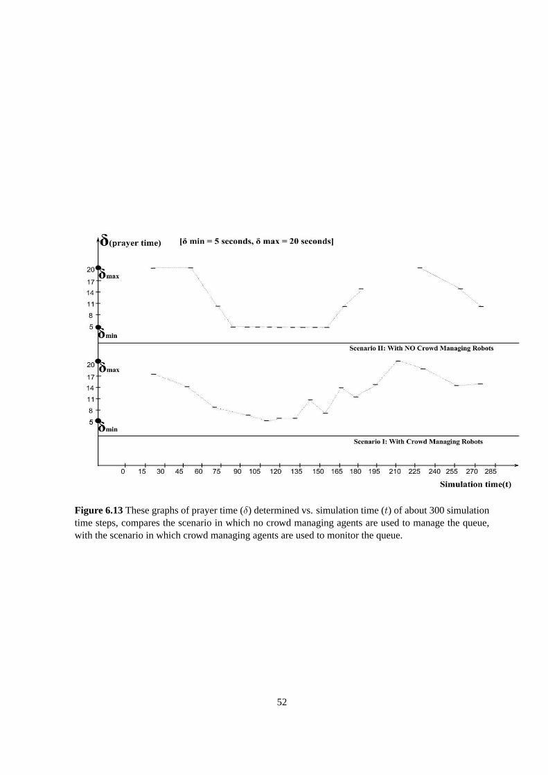
Figure 6.13These graphs of prayer time (δ) determined vs. simulation time (t) of about 300 simulationtime steps, compares the scenario in which no crowd managing agents are used to manage the queue,with the scenario in which crowd managing agents are used to monitor the queue.
52

TimeStamp (t)in seconds
Prayer time(δ) in sec-onds
OverallState of thequeue
27 20 Free flow62 20 Free flow102 20 Free flow137 20 Free flow169 20 Free flow202 20 Free flow241 20 Free flow278 20 Free flow
Table 6.3 Scenario I: Using crowd manage-ment agents to monitor the crowd.
TimeStamp (t)in seconds
Prayer time(δ) in sec-onds
OverallState of thequeue
27 20 Free flow62 20 Free flow102 20 Free flow137 20 Free flow169 20 Free flow202 20 Free flow241 20 Free flow278 20 Free flow
Table 6.4Scenario II: Using NO crowd man-agement agents.
TimeStamp (t)in seconds
Prayer time(δ) in sec-onds
OverallState of thequeue
18 15 Constant35 12 Constant51 8.2 Congestion62 6.3 Congestion69 5.7 Congestion78 7.4 Constant87 8.8 Constant101 8.4 Congestion112 10.2 Constant
Table 6.5 Scenario I: Using crowd manage-ment agents to monitor the crowd.
TimeStamp (t)in seconds
Prayer time(δ) in sec-onds
OverallState of thequeue
15 10 Constant28 10 Congestion39 5 Congestion47 5 Congestion56 5 Congestion64 5 Congestion75 5 Congestion83 5 Congestion92 10 Constant
Table 6.6Scenario II: Using NO crowd man-agement agents.
The observations shown in Tables 6.5, 6.6 are for a simulation run of very high in-flow rate which
may cause severe congestion. In the scenario of using crowd managing agents, the robot at the main
entrance detects the congestion and acts accordingly to control the in-flowrate. When there are no
robots, people continuously flow in to the queue, pushing themselves with highforce causing severe
congestion to lead to stampedes. The comparision of Tables 6.5, 6.6 shows that congestion (in a scenario
with robots) is brought under control and the prayer time at all simulation times determined is higher
than the minimum allotted prayer time and the average prayer time in scenario I (9.1s) is higher (by
36.4%) than the prayer time in scenario II (6.67s).
53

Chapter 7
Conclusions and Future Work
Stampedes are mass impulsive actions. Human stampedes are tragic and often occur either (i) when
people are in rush to acquire something of value, to reach a common destination, or (ii) when people are
in panic to escape from some danger, like when evacuating a building on fire. A study of stampedes oc-
curred over a period of time, showed that stampedes are frequent at religious festivals or at large crowd
gathering events (sports events and music concerts). Such stampedes are highly common in India, par-
ticularly at religious gatherings and pilgrimages, which may end in killing hundreds of people. It is a
common misconception, that the cause of deaths in these situations is trampling. Itis not simply due
to trampling, but, typically due to high forces exerted on each other leading to compressive asphyxiation.
In this dissertation, we discussed the scenario of crowding in long queuesat temples (pilgrims). At
a temple, the queue is a single directional flow of people rushing in at the queue entrance, to reach a
common destination (the main temple arena) where they can offer their prayersto a deity for some al-
lotted prayer time. Stampedes at such situations sometimes occur due to inadequate crowd management
measures. And sometimes highly congested areas are where the stampedes are initiated, but such areas
are usually not noticeable by the policemen present. Once the stampede is been initiated, controlling
the crowd that is out of order may need the involvement of forceful measures. Hence, there is a need for
crowd management and as a solution to managing crowd at such scenarios of long queues, we introduce
a set of robots which can move overhead the queue to be able to notice thosecongested areas that lead
to stampedes.
We developed a multi-agent simulation system, MAMAC (Multi-Agent MAnagementof Crowd),
to generate human agents crowd in long queues using a social force model.Crowd managing agents
(robots) are introduced into this sytem. These agents are capable of (i) monitoring the crowd at a height
above the queue, (ii) determining the crowd densities to estimate congestion levels and (iii) determining
the rates of flow of people that are used in interpreting various states of thequeue and to calculate ap-
propriate prayer time (time allotted for which people can offer their prayers). This multi-agent system,
54

moves the crowd managing agents using the algorithm developed for the methodof movement and gets
these agents to act to reduce congestion to achieve a stampede free flow. It also, adds or removes the
robots using the algorithm developed for determining the required number ofcrowd managing agents
for managing the long queue.
Method of Movement: The robots when placed on a track at a height overhead, the long queue
seems to be divided into a number of individual queues that can be monitoredand managed by each
robot to achieve an overall stampede free flow of people. The method of movement reads the current
positions of the robots and the flow rate values determined by each robot to determine the congestion
levels and states of the individual queues based on which the respectiverobots move and act to reduce
congestion.
Required Number of Robots: Not all the robots available are necessary to manage the queue at all
times. The required number of robots depend on the various states of the queue determined at different
simulation times. An algorithm was developed to add (or) remove a robot, depending on whether an
extra robot is needed to manage a congested area (or) whether a robotis monitoring an area that does
not need management, respectively.
The communication between the crowd managing agents is faster and more effective than the com-
munication between the members of a crowd management force (police or security). Our results show
that crowd managing agents can monitor the potential regions of congestion and take remedial actions
to prevent the occurrence of a stampede. Overall, the situation is under control and people get to spend
substantial amount of time, greater than the minimum allotted time infront of the deity, while using only
a required number of robots.
Future work includes developing strategies to manage the crowd in complex scenarios of queuing.
The crowd managing agents and the crowd management force can form a complimentary set of humans
and robotic agents, which can be used for managing crowds in various scenarios. And also extending
the techniques of crowd management for crowding scenarios with multi-directional flow of people.
55
Bibliography
[1] Agent Based Social Simulation.http://en.wikipedia.org/wiki/Agent-based_social_
simulation.
[2] Causes of Stampede. http://www.health24.com/Syndication/Yourhealth/News/
Stampede-how-it-happens-20120721.
[3] Level of Service.http://en.wikipedia.org/wiki/Level_of_service.
[4] Level of Service - Average area module for Queuing.http://en.wikipedia.org/wiki/Level_
of_service#Queueing.
[5] Love Parade Disaster.http://en.wikipedia.org/wiki/Love_Parade_disaster.
[6] People Counter using Thermal Imaging.http://en.wikipedia.org/wiki/People_counter#
Thermal_imaging.
[7] PhilSports Stadium Stampede.http://en.wikipedia.org/wiki/PhilSports_Stadium_
stampede.
[8] Sabarimala Stampede.http://en.wikipedia.org/wiki/2011_Sabarimala_stampede.
[9] The Hajj Pilgrimage Disasters.http://en.wikipedia.org/wiki/Incidents_during_the_
Hajj.
[10] L. Alon, C. Yiorgos, and L. Dani. Crowds by Example.Computer Graphics Forum, 26(3):655–664, Sept.
2007.
[11] A. L. Ballinas-Hernandez, A. Munoz Melendez, and A. Rangel-Huerta. Multiagent system applied to the
modeling and simulation of pedestrian traffic in counterflow. Journal of Artificial Societies and Social
Simulation, 14(3):2, 2011.
[12] S. Bandini, M. Federici, S. Manzoni, and G. Vizzari. Towards a methodology for situated cellular agent
based crowd simulations. In O. Dikenelli, M.-P. Gleizes, and A. Ricci, editors,Engineering Societies in
the Agents World VI, volume 3963 ofLecture Notes in Computer Science, pages 203–220. Springer Berlin
Heidelberg, 2006.
[13] A. E. Berlonghi. Understanding and planning for different spectator crowds.Safety Science, 18(4):239 –
247, 1995. ¡ce:title¿Engineering for Crowd Safety¡/ce:title¿.
56

[14] M. Bratman. Intention, Plans, and Practical Reason. The David Hume Series: Philosophy and Cognitive
Science Reissues. Harvard University Press, Cambridge, Massachusetts, 1987.
[15] C. Brown and E. L. Lewis. Protesting the invasion of cambodia: A case study of crowd behavior and
demonstration leadership.Polity, 30(4):pp. 645–665, 1998.
[16] N. Courty and T. Corpetti. Crowd motion capture.Comput. Animat. Virtual Worlds, 18(4-5):361–370, Sept.
2007.
[17] Z. Daoliang, Y. Lizhong, and L. Jian. Exit dynamics of occupant evacuation in an emergency.Physica A
Statistical Mechanics and its Applications, 363:501–511, May 2006.
[18] P. Davidsson. Multi agent based simulation: Beyond social simulation. InProceedings of the Second In-
ternational Workshop on Multi-Agent-Based Simulation-Revised and Additional Papers, MABS ’00, pages
97–107, London, UK, UK, 2001. Springer-Verlag.
[19] J. Drury and C. Cocking.The Mass Psychology of Disasters and Emergency Evacuations: A Research
Report and Implications for Practice. University of Sussex, 2007.
[20] F. Durupinar, J. Allbeck, N. Pelechano, and N. Badler. Creating crowd variation with the ocean personality
model. InProceedings of the 7th international joint conference on Autonomous agents and multiagent
systems - Volume 3, AAMAS ’08, pages 1217–1220, Richland, SC, 2008. International Foundation for
Autonomous Agents and Multiagent Systems.
[21] R. Eglese and F. De Silva. Integrating simulation modelling and gis: spatial decision support systems for
evacuation planning.Journal of the Operational Research Society, 51(4):423–430, 2000.
[22] K. Farahmand. Application of simulation modeling to emergency population evacuation. InProceedings of
the 29th conference on Winter simulation, WSC ’97, pages 1181–1188, Washington, DC, USA, 1997. IEEE
Computer Society.
[23] N. Farenc, S. R. Musse, E. Schweiss, M. Kallmann, O. Aune, R. Boulic, and D. Thalmann. A paradigm for
controlling virtual humans in urban environment simulations. Applied Artificial Intelligence, 14(1):69–91,
2000. Comput. Graphics Lab., Swiss Fed. Inst. of Technol., Lausanne, Switzerland.
[24] I. Farkas and T. Vicsek. Freezing by heating in a driven mesoscopic system.Phys. Rev. Lett., (84):1240–
1243, Jan. 2000.
[25] L. Festinger, A. Pepitone, and T. Newcomb. Some consequences of deindividuation in a group.Journal of
Abnormal and Social Psychology, (47):382–389, 1952.
[26] P. Fiorini and Z. Shiller. Motion planning in dynamic environments using velocity obstacles.The Interna-
tional Journal of Robotics Research, 17(7):760–772, 1998.
[27] J. Fruin. The Causes and Prevention of Crowd Disasters.In R. A. Smith and J. F. Dickie, editors,Engineer-
ing for Crowd Safety, Amsterdam, 1993. Elsevier.
[28] J. J. Fruin. Designing for pedestrians: A level of service concept.Highway Research Record, (355):1–15,
1971.
57

[29] S. J. Guy, J. Chhugani, C. Kim, N. Satish, M. Lin, D. Manocha, and P. Dubey. Clearpath: highly parallel
collision avoidance for multi-agent simulation. InProceedings of the 2009 ACM SIGGRAPH/Eurographics
Symposium on Computer Animation, SCA ’09, pages 177–187, New York, NY, USA, 2009. ACM.
[30] E. T. Hall. The Hidden Dimension. Anchor Books, 1966.
[31] T. Hamagami and H. Hirata. Method of crowd simulation byusing multiagent on cellular automata. In
Intelligent Agent Technology, 2003. IAT 2003. IEEE/WIC International Conference on, pages 46–52, 2003.
[32] D. Helbing. A mathematical model for the behavior of pedestrians.Behav. Sci., 36(4):298–310, Nov. 1991.
[33] D. Helbing. Empirical traffic data and their implications for traffic modeling.Phys. Rev. E, 55:R25–R28,
Jan 1997.
[34] D. Helbing. Traffic modeling by means of physical concepts. In D. E. Wolf, M. Schreckenberg and A.
Bachem (Eds.), Traffic and Granular Flow, pages 87–104, 1999.
[35] D. Helbing. Simulation of pedestrian crowds in normal and evacuation situations.Most, 21:21–58, 2002.
[36] D. Helbing, L. Buzna, A. Johansson, and T. Werner. Self-Organized Pedestrian Crowd Dynamics: Experi-
ments, Simulations, and Design Solutions.Transportation Science, 39(1):1–24, Feb. 2005.
[37] D. Helbing, I. Farkas, and T. Vicsek. Simulating dynamical features of escape panic.Nature,
407(6803):487–490, 2000.
[38] D. Helbing and P. Molnar. Social force model for pedestrian dynamics.Phys. Rev. E, 51:4282–4286, May
1995.
[39] D. Helbing and P. Molnar. Self-Organization Phenomena in Pedestrian Crowds.F. Schweitzer (ed.) Self-
Organization of Complex Structures: From Individual to Collective Dynamics, pages 569–577, 1997.
[40] D. Helbing, P. Moln’ar, I. J. Farkas, and K. Bolay. Self-organizing pedestrian movement.Environment and
Planning B-planning & Design, 28:361–383, 2001.
[41] D. Helbing and P. Mukerji. Crowd disasters as systemic failures: analysis of the Love Parade disaster.EPJ
Data Science, 1(1):1–40, 2012.
[42] D. Helbing and T. Vicsek. Optimal self-organization.New Journal of Physics, 1(13.1):1–13, 1999.
[43] C. M. Henein and T. White. Agent-based modelling of forces in crowds. InIn Multi-Agent and MultiAgent-
Based, pages 173–184. Springer-Verlag, July 2004.
[44] C. M. Henein and T. White. Macroscopic effects of microscopic forces between agents in crowd models.
Physica A: Statistical Mechanics and its Applications, 373(0):694 – 712, 2007.
[45] A. Kirchner and A. Schadschneider. Simulation of evacuation processes using a bionics-inspired cellular au-
tomaton model for pedestrian dynamics.Physica A: Statistical Mechanics and its Applications, 312(12):260
– 276, 2002.
[46] J. Kirkland and A. Maciejewski. A simulation of attempts to influence crowd dynamics. InSystems, Man
and Cybernetics, 2003. IEEE International Conference on, volume 5, pages 4328–4333 vol.5, 2003.
58
[47] F. Klgl and G. Rindsfser. Large-scale agent-based pedestrian simulation. In P. Petta, J. Mller, M. Klusch,
and M. Georgeff, editors,Multiagent System Technologies, volume 4687 ofLecture Notes in Computer
Science, pages 145–156. Springer Berlin Heidelberg, 2007.
[48] P. A. Langston, R. Masling, and B. N. Asmar. Crowd dynamics discrete element multi-circle model.Safety
Science, 44(5):395 – 417, 2006.
[49] R. Leggett. Real-Time Crowd Simulation:A Review. 2004.
[50] X. Li, W. Mao, D. Zeng, and F.-Y. Wang. Agent-based social simulation and modeling in social computing.
In C. C. Yang, H. Chen, M. Chau, K. Chang, S.-D. Lang, P. Chen, R. Hsieh, D. Zeng, F.-Y. Wang, K. Carley,
W. Mao, and J. Zhan, editors,Intelligence and Security Informatics, volume 5075 ofLecture Notes in
Computer Science, pages 401–412. Springer Berlin Heidelberg, 2008.
[51] J. Lofland.Protest: Studies of Collective Behavior and Social Movements. Transaction Pub, 1985.
[52] G. G. Lovas. Modeling and simulation of pedestrian traffic flow. Transportation Research Part B: Method-
ological, 28(6):429 – 443, 1994.
[53] C. McPhail. The Myth of the Madding Crowd. Social Institutions and Social Change Series. Aldine de
Gruyter, 1991.
[54] S. Mitchell and E. Radwan. Heuristic Priority Ranking of Emergency Evacuation Staging to Reduce Clear-
ance Time.Transportation Research Record: Journal of the Transportation Research Board, pages 219–
228, 2006.
[55] R. Momboisse.Riots, revolts, and insurrections. C. C. Thomas, 1967.
[56] S. R. Musse, C. R. Jung, J. C. S. Jacques, Jr., and A. Braun. Using computer vision to simulate the motion
of virtual agents: Research articles.Comput. Animat. Virtual Worlds, 18(2):83–93, May 2007.
[57] S. R. Musse and D. Thalmann. A Model of Human Crowd Behavior: Group Inter-Relationship and Collision
Detection Analysis. InWorkshop Computer Animation and Simulation of Eurographics, pages 39–51, 1997.
[58] S. R. Musse and D. Thalmann. Hierarchical model for realtime simulation of virtual human crowds.IEEE
Transactions on Visualization and Computer Graphics, 7(2):152–164, Apr. 2001.
[59] D. Myers.Social psychology. McGraw-Hill, eighth edition, 2005.
[60] T. Osaragi. Modeling of pedestrian behavior and its applications to spatial evaluation. InProceedings of the
Third International Joint Conference on Autonomous Agentsand Multiagent Systems - Volume 2, AAMAS
’04, pages 836–843, Washington, DC, USA, 2004. IEEE Computer Society.
[61] X. Pan. Computational Modeling of Human and Social Behaviors for Emergency Egress Analysis. PhD
thesis, Civil and Environmental Engineering Dept., Stanford University, June 2006.
[62] X. Pan, C. S. Han, K. Dauber, and K. H. Law. Human and social behavior in computational modeling and
analysis of egress.Automation in Construction, 15(4):448 – 461, 2006. ¡ce:title¿The first conference on the
Future of the AEC Industry (BFC05)¡/ce:title¿.
[63] X. Pan, C. S. Han, K. Dauber, and K. H. Law. A multi-agent based framework for the simulation of human
and social behaviors during emergency evacuations.AI Soc., 22(2):113–132, Oct. 2007.
59
[64] X. Pan, C. S. Han, and K. H. Law. A multi-agent based simulation framework for the study of human and.
In Social Behavior in Egress Analysis. in The International Conference on Computing in Civil Engineering,
(Cancun), pages 12–15, 2005.
[65] D. Parisi and C. Dorso. Morphological and dynamical aspects of the room evacuation process.Physica A:
Statistical Mechanics and its Applications, 385(1):343 – 355, 2007.
[66] N. Pelechano, J. M. Allbeck, and N. I. Badler. Controlling individual agents in high-density crowd simula-
tion. In Proceedings of the 2007 ACM SIGGRAPH/Eurographics symposium on Computer animation, SCA
’07, pages 99–108, Aire-la-Ville, Switzerland, Switzerland, 2007. Eurographics Association.
[67] N. Pelechano and A. Malkawi. Evacuation simulation models: Challenges in modeling high rise building
evacuation with cellular automata approaches.Automation in Construction, 17(4):377 – 385, 2008.
[68] M. Pidd, F. de Silva, and R. Eglese. A simulation model for emergency evacuation.European Journal of
Operational Research, 90(3):413 – 419, 1996.
[69] T. Postmes and R. Spears. Deindividuation and antinormative behavior: A meta-analysis.Psychological
Bulletin, 123(3):238–259, 1998.
[70] Y. Rao, L. Chen, Q. Liu, W. Lin, Y. Li, and J. Zhou. Real-time control of individual agents for crowd
simulation.Multimedia Tools Appl., 54(2):397–414, Aug. 2011.
[71] S. Reicher.The Psychology of Crowd Dynamics, pages 182–208. Blackwell Publishers Ltd, 2008.
[72] S. D. Reicher, R. Spears, and T. Postmes. A social identity model of deindividuation phenomena.European
Review of Social Psychology, 6(1):161–198, 1995.
[73] C. W. Reynolds. Flocks, herds and schools: A distributed behavioral model.SIGGRAPH Comput. Graph.,
21(4):25–34, Aug. 1987.
[74] C. W. Reynolds. Steering Behaviors For Autonomous Characters. InGame Developers Conference, pages
763–782, San Jose, California, 1999.
[75] N. Ronald and L. Sterling. A BDI Approach to Agent-BasedModelling of Pedestrians. InProceedings of
the 19th European Conference on Modelling and Simulation (ECMS), pages 169–174. European Council
for Modelling and Simulation, 2005.
[76] P. Saboia and S. Goldenstein. Crowd simulation: Improving pedestrians’ dynamics by the application of
lattice-gas concepts to the social force model. InGraphics, Patterns and Images (Sibgrapi), 2011 24th
SIBGRAPI Conference on, pages 41–47, 2011.
[77] N. Saiwaki, T. Komatsu, and S. Nishida. Automatic generation of moving crowds in the virtual environment.
In Proceedings of the First International Conference on Advanced Multimedia Content Processing, AMCP
’98, pages 422–432, London, UK, UK, 1999. Springer-Verlag.
[78] S. M. Sanchez and T. W. Lucas. Exploring the world of agent-based simulations: simple models, complex
analyses: exploring the world of agent-based simulations:simple models, complex analyses. InProceedings
of the 34th conference on Winter simulation: exploring new frontiers, WSC ’02, pages 116–126. Winter
Simulation Conference, 2002.
60

[79] M. Schreckenberg and S. Sharma.Pedestrian and evacuation dynamics. Springer, 2001.
[80] A. Sharma. Crowd-behavior prediction using subjective factor based multi-agent system. InSystems, Man,
and Cybernetics, 2000 IEEE International Conference on, volume 1, pages 298–300 vol.1, 2000.
[81] J. Sime. Crowd psychology and engineering.Safety Science, 21(1):1 – 14, 1995.
[82] G. Still. Crowd Dynamics. PhD thesis, University of Warwick, UK, July 2000.
[83] G. K. Still. Love Parade Incident - Expert Report. December 2011.
[84] M. Sung, M. Gleicher, and S. Chenney. Scalable behaviors for crowd simulation.Comput. Graph. Forum,
pages 519–528, 2004.
[85] H. Tajfel and J. C. Turner.An integrative theory of intergroup conflict, pages 33–47. Brooks/Cole, 1979.
[86] C. Tilly. From mobilization to revolution. Addison-Wesley Pub. Co., 1978.
[87] M. C. Toyama, A. L. C. Bazzan, and R. da Silva. An agent-based simulation of pedestrian dynamics:
from lane formation to auditorium evacuation. InProceedings of the fifth international joint conference
on Autonomous agents and multiagent systems, AAMAS ’06, pages 108–110, New York, NY, USA, 2006.
ACM.
[88] A. Treuille, S. Cooper, and Z. Popovic. Continuum crowds.ACM Trans. Graph., 25(3):1160–1168, July
2006.
[89] B. Ulicny and D. Thalmann. Crowd simulation for interactive virtual environments and vr training systems.
In Proceedings of the Eurographic workshop on Computer animation and simulation, pages 163–170, New
York, NY, USA, 2001. Springer-Verlag New York, Inc.
[90] Y. Weifeng and T. Kang Hai. A novel algorithm of simulating multi-velocity evacuation based on cel-
lular automata modeling and tenability condition.Physica A: Statistical Mechanics and its Applications,
379(1):250–262, 2007.
[91] K. H. L. Wong and M. Luo. Computational tool in infrastructure emergency total evacuation analysis. In
Proceedings of the 2005 IEEE international conference on Intelligence and Security Informatics, ISI’05,
pages 536–542, Berlin, Heidelberg, 2005. Springer-Verlag.
[92] K. Yamamoto, S. Kokubo, and K. Nishinari. New approach for pedestrian dynamics by real-coded cellular
automata (rca). In S. Yacoubi, B. Chopard, and S. Bandini, editors, Cellular Automata, volume 4173 of
Lecture Notes in Computer Science, pages 728–731. Springer Berlin Heidelberg, 2006.
[93] K. Yamamoto, S. Kokubo, and K. Nishinari. Simulation for pedestrian dynamics by real-coded cellular
automata (rca).Physica A: Statistical Mechanics and its Applications, 379(2):654–660, June 2007.
[94] K. Yamori. Going with the flow : Micro-macro dynamics in the macrobehavioral patterns of pedestrian
crowds.Psychological review, 105(3):530–557, 1998.
[95] W. Yu and A. Johansson. Modeling crowd turbulence by many-particle simulations. Phys. Rev. E,
76:046105, Oct 2007.
[96] N. Zarboutis and N. Marmaras. Design of formative evacuation plans using agent-based simulation.Safety
Science, 45(9):920 – 940, 2007.
61