Embed Size (px)
Citation preview

MULTI AGENT BASED CONTROL AND PROTECTION
FOR AN INVERTER BASED MICROGRID
Asitha Lakruwan Kulasekera
(108020B)
Thesis submitted in partial fulfilment of the requirements for the degree Master of
Science
Department of Mechanical Engineering
University of Moratuwa
Sri Lanka
February 2012

i
DECLARATION
I declare that this is my own work and this thesis does not incorporate without
acknowledgement any material previously submitted for a Degree or Diploma in any
other University or institute of higher learning and to the best of my knowledge and
belief it does not contain any material previously published or written by another
person except where the acknowledgement is made in the text.
Also, I hereby grant to University of Moratuwa the non-exclusive right to reproduce
and distribute my thesis/dissertation, in whole or in part in print, electronic or other
medium. I retain the right to use this content in whole or part in future works (such as
articles or books).
Signature: Date:
The above candidate has carried out research for the Masters/MPhil/PhD thesis under
my supervision.
Signature of the supervisor: Date:
Signature of the supervisor: Date:
ii
Table of Contents
List of figures ........................................................................................................... v
List of tables ........................................................................................................... vi
List of abbreviations ............................................................................................... vii
1. Introduction ...................................................................................................... 1
1.1. Emergence of smarter electrical grids and microgrids ................................. 1
1.1.1. Smart grid ........................................................................................... 2
1.1.2. Smarter microgrids.............................................................................. 3
1.2. Use of multi agent systems ......................................................................... 4
1.3. Thesis statement ......................................................................................... 5
1.3.1. Methodology ....................................................................................... 6
1.4. Contributions ............................................................................................. 8
1.5. Organization .............................................................................................. 8
2. Literature Review ............................................................................................. 9
2.1. A Multi agent system ................................................................................. 9
2.1.1. Features of a multi agent system ....................................................... 10
2.2. Multi agent systems and applications ....................................................... 11
2.3. Toolkits/frameworks for development of multi agent systems .................. 12
2.4. JADE and Zeus – a comparative overview ............................................... 12
2.5. JADE agent building toolkit ..................................................................... 14
2.5.1. JADE architecture ............................................................................. 14
2.6. Recent applications of multi agent systems in microgrids ......................... 17
2.6.1. Distributed control ............................................................................ 17
2.6.2. Electricity trading ............................................................................. 19
iii
2.6.3. Optimization ..................................................................................... 20
2.6.4. Power restoration .............................................................................. 21
2.7. Control architectures ................................................................................ 21
3. Conceptual design of dual-layered MAS ......................................................... 24
3.1. Dual layered architecture ......................................................................... 24
3.2. Agents used in the dual-layered MAS ...................................................... 26
4. Implementation of dual-layered MAS ............................................................. 28
4.1. Dual-layered Multi agent system implementation in JADE ...................... 28
4.1.1. Agent specification ........................................................................... 28
4.1.2. Application analysis .......................................................................... 29
4.1.3. Application design ............................................................................ 30
4.1.4. MAS algorithm implementation ........................................................ 34
4.2. Running multi agent system application ................................................... 36
5. Simulations and Results .................................................................................. 37
5.1. Description of simulation circuit .............................................................. 38
5.2. Intentional islanding during a fault ........................................................... 39
5.2.1. Messages exchanged among agents and physical entities .................. 40
5.2.2. Updates to the ontology .................................................................... 42
5.2.3. Results and discussion ...................................................................... 43
5.3. Protecting critical loads during intentional islanding ................................ 45
5.3.1. Messages exchanged among agents and physical entities .................. 46
5.3.1. Updates to the ontology .................................................................... 46
5.3.2. Results and discussion ...................................................................... 47
5.4. Managing critical loads during islanded operation .................................... 49
5.4.1. Messages exchanged among agents and physical entities .................. 50
iv
5.4.1. Updates to the ontology .................................................................... 51
5.4.2. Results and discussion ...................................................................... 52
6. Conclusions and Future Directions ................................................................. 55
6.1. Conclusions ............................................................................................. 55
6.2. Future work ............................................................................................. 56
References ............................................................................................................. 57
Section 4: Impact of Research results ...................... Error! Bookmark not defined.
Section 5: Publications ............................................. Error! Bookmark not defined.
v
LIST OF FIGURES
Figure 1.1 A smart grid application .......................................................................... 2
Figure 1.2 Conceptual model of a microgrid ............................................................. 4
Figure 2.1 Example of a multi agent system ............................................................. 9
Figure 2.2 JADE architecture ................................................................................. 15
Figure 2.3 Basic multi agent system structure ......................................................... 22
Figure 2.4 Single layered multi agent system architecture ...................................... 23
Figure 3.1 Proposed dual layered MAS architecture ............................................... 24
Figure 3.2 Interaction between agents in the dual layered multi agent architecture .. 25
Figure 4.1 Dual-layered MAS ontology .................................................................. 31
Figure 4.2 Control algorithm for multi agent system operation ............................... 34
Figure 4.3 Establishing communication between simulation environment and MAS36
Figure 5.1 Simulated microgrid test-bed ................................................................. 38
Figure 5.2 Test-bed set-up for case study 1 ............................................................. 39
Figure 5.3 Control flow chart for intentional islanding ........................................... 40
Figure 5.4 Key messages exchanged between agents during islanding .................... 41
Figure 5.5 Line to line voltages during intentional islanding ................................... 43
Figure 5.6 Test-bed set-up for case study 2 ............................................................. 45
Figure 5.7 Line to line voltages during securing critical loads ................................ 48
Figure 5.8 Test-bed set-up for case study 3 ............................................................. 49
Figure 5.9 Control flow chart for load management during islanded operation ....... 50
Figure 5.10 Line to line voltages during islanded operation .................................... 52
Figure 6.1 Proposed microgrid test-bed .................................................................. 56

vi
LIST OF TABLES
Table 2.1 A comparison between JADE and ZEUS platforms ................................ 13
Table 4.1 Microgrid domain knowledge, attributes and initial values ...................... 33
Table 5.1 Updated concepts, initial and updated values for case study 1 ................. 42
Table 5.2 Updated concepts, initial and updated values for case study 2 ................. 46
Table 5.3 Updated concepts, initial and updated values for case study 3 ................. 51
Table 5.4 Priority revision during islanded mode .................................................... 54
vii
LIST OF ABBREVIATIONS
Abbreviation Description
DG Distributed Generation
DSM Demand Side Management
FIPA Foundation for Intelligent Physical Agents
FOSS Free and Open Source Software
GHG Green House gasses
GUI Graphical User interface
JADE Java Agent Development Framework
MAS Multi Agent Systems
NCRES Non-conventional Renewable Energy Sources
OS Operating Systems
PC Personal Computer
PCC Point of Common Coupling
PV Photovoltaic (cell)
PWM Pulse Width Modulation
SCADA Supervisory Control and Data Acquisition

1
SECTION 3
1. INTRODUCTION
An agent is a software entity which can operate on its own by responding and
reacting with its environment. A collection of such agents collaborating to achieve an
overall goal can be considered as a multi agent system (MAS). Such systems are
ideal for the complex real-time control problems that are faced with today.
Multi agent systems are being widely used in computer systems and e-commerce
applications [1], [2]. The collaborative social ability of agents is enhanced by the
presence of fast communication capabilities in such applications (i.e. web/internet).
With the integration of fast communication capabilities into power grids in building
future-proof smart(er) grids, the possibility of integrating multi agent systems to
power engineering is becoming real [3]. The unique feature set available in multi
agent systems is proving to be the correct fit in terms of the requirements in power
engineering applications.
This section provides an introduction to the research area, which the application of
multi agent systems in microgrid applications. The importance of this work is briefly
explained and is followed by the thesis statement.
1.1. Emergence of smarter electrical grids and microgrids
The ever increasing demand for electrical power has been a major challenge for the
electrical supply authorities worldwide [4]. The present grid systems which have
mostly been built over the last century are rapidly aging [4]. These legacy grid
infrastructures are becoming increasingly congested and are seen as incapable of
meeting the future energy needs of an information economy. The renewed interest in
climate change mitigation through reduced Green House Gas (GHG) emissions has
ushered in a need of greener generation and utilizing renewables in the energy mix.
Therefore, these power systems have to become smarter, more reliable and more
robust in taking on renewable energy sources without losing stability and efficiency.

2
1.1.1. Smart grid
A smart grid is the use of sensors, communications, computational capabilities and
control to enhance the overall functionality of the electric power grid [4]. This
concept is depicted in Figure 1.1.
Figure 1.1 A smart grid application
Smarter grids are a step forward in overcoming the limitations of legacy electricity
infrastructure[4]. They must be automated and be able to behave as a distributed
energy delivery system, that incorporates two-way flow of electricity & information
including advanced sensing & monitoring [4] along with the following
functionalities [5].
• Visualizing the power grid in real time
• Increasing system capacity
• Relieving bottlenecks
• Enabling a self-healing network
• Enabling enhanced connectivity to consumers
• Allowing incorporation of distributed non-conventional renewable energy
sources (NCRES)

3
One rising feature integrated into smart(er) grids is the microgrid concept [6]. It
allows for far greater control over improving grid reliability [5], resilience towards a
wide range of threats to the electrical grid [7], allow for easy incorporation of
distributed generation [8], reduce GHG emissions etc. Therefore, in developing the
future smarter grid, implementation of successful microgrids are vital.
1.1.2. Smarter microgrids
Smarter microgrids are part of the solution to the problems faced by legacy electrical
infrastructure. Their capability to house local embedded generators as distributed
generation and be locally controlled offers various advantages over legacy systems.
In order to realize the potential of such smarter systems, a high degree of distributed
control is required [6]. As a novel method in providing this flexible distributed
control requirement, Multi Agent Systems (MAS) are stepping forward.
Centralized bulk generation facilities are giving way to, more distributed small scale
generation. Distributed generation (DG) introduces the capability of embedding a
wide range of low emission and potentially lower cost generation options. Such
options can include internal combustion engines, micro-turbines and non-
conventional renewable energy sources such as solar photo voltaic, wind, biomass,
mini/micro-hydro and even waste-to-energy systems. These smaller generation
technologies allow the sources to be placed optimally with respect to the loads, thus
reducing emissions and transmission losses, while also allowing for local control
instead of central dispatching [6].
Such DG systems provide the potential to take a sub-system approach in working
with microgrids. During a disturbance in the main grid, local generation and their
loads can be separated from the utility and isolate the local loads from the
disturbance, while maintaining the integrity of the main utility grid. This isolation is
carried out at a single point of connection to the main utility known as point of
common coupling (PCC). This capability, known as islanding, requires high
reliability and flexibility from the microgrid. These requirements can be met by
having peer-to-peer control and plug-and-play capabilities for each entity in the
microgrid.
4
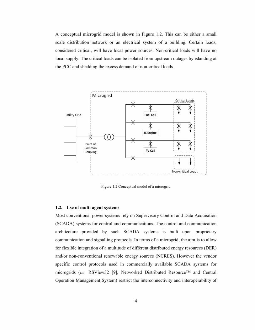
A conceptual microgrid model is shown in Figure 1.2. This can be either a small
scale distribution network or an electrical system of a building. Certain loads,
considered critical, will have local power sources. Non-critical loads will have no
local supply. The critical loads can be isolated from upstream outages by islanding at
the PCC and shedding the excess demand of non-critical loads.
Figure 1.2 Conceptual model of a microgrid
1.2. Use of multi agent systems
Most conventional power systems rely on Supervisory Control and Data Acquisition
(SCADA) systems for control and communications. The control and communication
architecture provided by such SCADA systems is built upon proprietary
communication and signalling protocols. In terms of a microgrid, the aim is to allow
for flexible integration of a multitude of different distributed energy resources (DER)
and/or non-conventional renewable energy sources (NCRES). However the vendor
specific control protocols used in commercially available SCADA systems for
microgrids (i.e. RSView32 [9], Networked Distributed Resource™ and Central
Operation Management System) restrict the interconnectivity and interoperability of
5
diverse systems. Such restrictions can result in increased deployment costs and
prevent microgrid rollout.
Use of multi agent systems to provide distributed control capabilities to the
microgrid applications offers various advantages over conventional SCADA systems.
Multi agent system development platforms are available as Free and Open Source
(FOSS) applications and most of them are based on Java, making them platform
independent. They can also be combined with external programming to interface
with different external hardware and software systems [1]. These advantages make
multi agent systems more suited for microgrid control. In addition, multi agent
systems also have the following advantages in context of microgrid control:
i. Multi agent systems are inherently flexible and extensible.
ii. Local loads and sources will have different specifications and systems.
Therefore, an intelligent distributed control system is the best solution.
iii. The microgrid will have to take rapid autonomous decisions regarding
seamless transition to islanded mode from grid connected mode and
protecting critical loads by load shedding.
iv. Multi agent systems allow for a complex task to be broken down into several
smaller tasks assigned to a team of agents. This allows for easier handling of
a larger problem.
1.3. Thesis statement
The objective of this research is to design, develop and simulate a multi agent system
that enables real-time energy management of a microgrid. This will include the
management and control procedures during transition from grid-connected to
islanding mode; the algorithms to manage priority levels of the connected loads and
protect critical loads utilizing available limited capacity from local embedded
generators during outages.
Novel MAS which provides scalable and robust distributed control architecture for
microgrid application is presented in the thesis. The MAS model is designed using
6
the JADE (Java Agent Development framework) platform and is implemented on a
simulated test-bed in MATLAB/SIMULINK.
The steps taken to realize the objectives of the thesis statement are listed below, and
are further detailed in Section 1.3.1:
1. Identification of suitable agent building framework
2. Design of Multi agent system architecture
3. Development of Multi agent system
4. Integration of the multi agent system and the microgrid simulation
5. Validation of results using simulation studies
1.3.1. Methodology
the methodology consists of the following five steps:
Step 1: Identification of suitable agent building framework
Several commercial and open-source multi agent system building toolkits are
currently available today for developing complex multi agent system in which the
design phase has been simplified [10], [11]. Such tool kits have been assessed in
literature in terms of time required for analysis and design, code generation,
integration with external code, response time, the number of messages exchanged
among agents etc. Further details regarding the selection of a suitable toolkit is
discussed in Section 2.4.
Step 2: Multi agent system architecture Design
The multi agent system aims to provide control and protection system for an inverter
based microgrid. The aim is to break down a larger goal into several smaller tasks
and delegate them to individual entities rather than to a single controller. Further
details on designing the multi agent architecture is presented in Section 3.

7
Step 3: Development of dual-layered multi agent system
Developing a multi agent system using a selected tool kit consists of following steps.
Initially, the abilities of each agent have to be specified, followed by identifying each
of their roles and responsibilities, through building role models and defining social
and domain responsibilities. Then the ontology of the system has to be created based
on modelling their knowledge or facts. All of these are concluded by creating the
agents and generating the code. This process is detailed in Section 4.
Step 4: Integration of the multi agent system and the microgrid simulation
The developed multi agent system attempts to control physical entities or a
simulation of the same. The multi agent system and the simulation are inherently in
two domains. The multi agent system runs on a JAVA platform while the simulation
is run on a simulating environment (i.e. MATLAB/SIMULINK). Therefore, in order
to establish communication between the two domains, for sensing and control
TCP/IP is used. A third party TCP/IP server is utilized as an interface to MATLAB
and it connects to another middle server which allows multiple simultaneous TCP/IP
connections. The middle server is required because; the interface allows only a single
connection at a time. Details regarding the creation of this interface are given in
Section 4.2.
Step 5: Validation of results using simulation studies
Three case studies are carried out to verify the implementation of the multi agent
system within a simulated microgrid test-bed environment. They demonstrate the
functionality of the system in islanding, protecting/securing supply to critical loads
and managing load priorities during islanded mode operation. The case studies and
their results are presented in detail in Section 5. Details of the microgrid test-bed
used for simulations are given in Section 5.1.

8
1.4. Contributions
In summary, the proposed multi-agent system control architecture is designed,
developed and simulated in several simulation case studies. It is expected that this
research will provide an insight into the design and development of a multi-agent
system. Furthermore, this research also contributes novel control architecture to
increase effectiveness of multi-agent system in the context of microgrids.
Specifically, this comprises control algorithms for managing the available limited
supply from local embedded sources to protect local critical loads during fault/s in
the main grid.
1.5. Organization
Rest of the thesis is organized as follows. Section 2 summarizes related work.
Sections 3 and 4 explain the methodology presented in Section 1 in more detail.
Section 5 presents the case studies and results, and the final section presents
conclusions and future work.
9
2. LITERATURE REVIEW
An agent system is hardware or software entity that possesses social coordination
and communication capabilities and capable of achieving a larger overall goal by
tackling smaller individual tasks. Agents have the ability to operate within its
environment to achieve its goal by sharing knowledge with other agents or taking
initiative.
Even a single agent can operate as a system, by reacting and interacting with its
environment. Such an agent will require specific programming to provide itself with
individual knowledge, actions and goals. Any other agents in the same environment
will not have any effect on the operation of such an agent.
2.1. A Multi agent system
A collection of social, collaborative agents constitute a multi agent system. All the
agents will inherit a set of common goals, and react to change in the environment,
make decisions to achieve those goals, or help other agents in achieving their goals
[1]. In contrast to single agent systems, other agents will also be a part of any agent’s
environment.
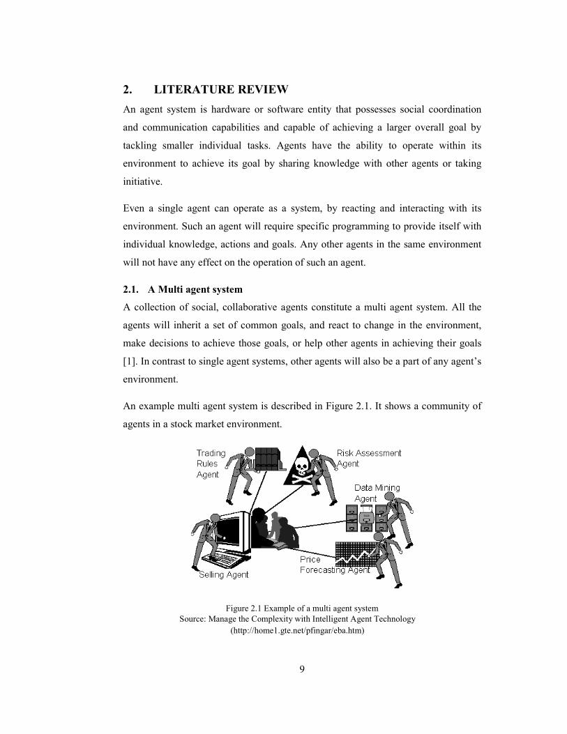
An example multi agent system is described in Figure 2.1. It shows a community of
agents in a stock market environment.
Figure 2.1 Example of a multi agent system
Source: Manage the Complexity with Intelligent Agent Technology
(http://home1.gte.net/pfingar/eba.htm)

10
The selling agent only has direct knowledge of potential buyers and maximizing the
profit. Other agents will know about their own domains. The trading rules agent
knows of all the rules and regulations; the risk assessment agent is able to assess the
risk associated with any stock; Data mining agent is able to access and understand
patterns in the sales data and the forecasting agent is able to forecast the rise and fall
of stock prices. The selling agent can make a more educated decision on trading a
particular stock by collaborating with his fellow agents, than on his own. He can
communicate with the other agents in his environment and ask for any supporting
information that will enable him to maximize his sales and/or profits.
2.1.1. Features of a multi agent system
As the aim of this thesis is to implement a multi agent system for distributed control
(intelligence), the following available feature set is ideally suited for such
applications.
Autonomy – agents are capable of operating without human supervision.
Social ability – agents are able to communicate with each other as well as human
operators using a common language.
Reactivity – agents are able to identify and react to changes in the environment.
Proactivity – agents take decisions or initiatives based on their assigned
objectives/goals.
Agents also hold certain knowledge or beliefs regarding their existence or their
environment. This knowledge and beliefs enable the agents to take decisions
regarding changes in their environment and seek to fulfil their objectives. In addition
to these features, agents have all or some of the following capabilities as well.

11
Data collection – an agent contains or will be able to collect data to build-up
knowledge regarding its environment, and assist fellow agents
making their decisions.
Social knowledge – the multi agent system contains an agent who helps the other
agents to know about each other’s existence and share their
capabilities (i.e. yellow pages service).
Learning – agents have learning capabilities to update their knowledge
and beliefs based on changes in the environment, and updates
from fellow agents.
Communication – all agents in the multi agent system should have a clearly
defined set of protocols regarding their communication with
humans or other agents.
2.2. Multi agent systems and applications
Multi agent systems are becoming more and more ubiquitous in the world. Recently,
multi agent systems are being implemented in a many fields such as mathematics,
physics, engineering sciences, and social science communities [12]. They have been
used in a wide array of applications ranging from computing and processing [13–16],
robotics and control systems [17–21], transportation [22–25], aerospace and nuclear
engineering in recent literature. There is a rising trend of applying multi agent
systems in power engineering applications for microgrids which is discussed in detail
in Section 2.4.

12
2.3. Toolkits/frameworks for development of multi agent systems
A multi agent system can be built from base coding. However, this is not necessary
as there are many easily available agent development tool kits where the agent
development process has been simplified. There are a number of open-source agent
development toolkits available, such as: Aglets software development kit [26],
Voyager [27], Zeus [11], JADE [10], Tracy [28], SPRINGS [29], and Skeleton [30].
Performance analysis of these agent development toolkits has been comprehensively
discussed in [31–38] in terms of time taken for analysis and design, code generation,
integration with external code, response time, the number of messages exchanged
among agents etc.. Based on these evaluations JADE and ZEUS are initially short
listed as potential contenders. Further analysis carried out to select the best suited
platform is presented in the following Section 2.4.
Step 1: Identification of suitable agent building framework
2.4. JADE and Zeus – a comparative overview
In selecting an agent tool kit / platform for an open-source development application it
is important to select one which is based on a common standard. The established
standard for agent systems is IEEE’s standard on Foundation for Intelligent Physical
Agents (FIPA) [39]. Based on the development platform of a well-known standard
will allow for easier inter-operability between different systems, resulting in
universal applicability. Therefore, the main criteria in selecting the best suited toolkit
for this application are compliance with FIPA standards.
Several studies in the literature [31], [33], [37] have compared the performance of
JADE and ZEUS in terms of availability, design and analysis, number of lines of
code, response time etc. A comparison of JADE and ZEUS platforms are given in
Table 2.1.
.

13
Table 2.1 A comparison between JADE and ZEUS platforms
JADE ZEUS
Free and open source Free and open source
FIPA Compliant FIPA Compliant
JAVA Based JAVA Based
Agent Communication Language (ACL) Communication
ACL and Knowledge Query
Manipulation Language (KQML)
Provides authentication Some security capabilities
Decent GUI User friendly GUI
Lower latency in complex systems Higher latency in complex systems
JADE and Zeus along with JATLite and Skeleton are comprehensively evaluated in
[31], grouping them together based on Java and availability of GUI. These four are
evaluated for use in a web-based news retrieval system. The author has evaluated
their performance based on run-time and software building capabilities. The
evaluated parameters in terms of software building characteristics are: time required
for analysis and design of multi-agent system; time required for code generation;
time required for integration of agent with external code; time required for testing
and debugging the system; number of lines in the code and number of new Java
classes and reused classes to build news agents in the system. Selected parameters
for evaluating run-time characteristics are: response time and number of messages
exchanged among agents. While the results show both to be similar in terms of
software building, JADE outperforms ZEUS in terms of run-time performance.
JADE, ZEUS and Skeleton are compared in terms of number of documents requested
from a web server versus response time while varying the number of web-agents in
[33], which show JADE outperforms all others for complex applications.

14
In applying a multi agent system for a microgrid or power application, complex
systems maybe required with (near) real-time performance. Therefore response time
and the number of messages exchanged become critical. A delay of 0.1 s caused by
20-25 excess messages will be visible on the power distribution. Therefore JADE
becomes the most suitable tool for the application.
2.5. JADE agent building toolkit
JADE (Java Agent Development Framework) is an open source agent development
toolkit developed and distributed by Telecom Italia under the LGPL (Library Gnu
Public License) license [10]. It is a software development platform which provides
middleware functionalities independent of application and simplify agent creation
[1]. This middleware functionality [40] is provided by:
i. run-time environment where the agents exist
ii. vast class library for simplifying agent development
iii. suite of graphical tools that allow for simple administration and monitoring
of agents
JADE is based on the ubiquitous JAVA platform which makes it platform
independent and highly versatile. Details of the JADE architecture are presented in
Section 5.2.1.
2.5.1. JADE architecture
Each JADE run-time environment in operation is called a container, which can
contain several agents. A set of containers are called a platform. Each platform must
have a primary or main container, and all other secondary containers must register
with it as soon as they are created / initialized. These secondary containers are called
normal containers and must be told where to find the main container in their
platform. If another main container is created it will constitute a different platform.
The agents in these containers can communicate with one another, even if they are in

15
the same container, different containers in the same platform or on different
platforms, using the network protocol stack provided by JADE. These notions are
depicted in Figure 2.2 [40].
When the main container is started, it also includes the following two special agents
(these are automatically started):
AMS (Agent Management System) Agent: this agent provides a unique name (Agent
ID or AID) to each agent in the platform (naming service) and represents the
authority in the platform to create/kill agents on remote containers.
DF (Directory Facilitator): this agent provides a Yellow Pages service, using which
an agent can find other agents with capabilities / information it requires in order to
achieve its goals.
Figure 2.2 JADE architecture
In Figure 2.2, A1 to A5 denote agents in two platforms 1 and 2. Agents A2 and A3
are in the same container, Agents A1 and A4 are in different containers, while all of

16
them are in the same platform. Agent A5 is in the main container of a different
platform. Each main container hosts its own AMS and DF.
Agents may need to carry out parallel negotiations and each negotiation will need to
proceed at its own pace. Normally for a software entity/program this can be done by
assigning a thread. Modern OS designs limit the number of concurrent threads.
Therefore, in order for efficient parallel operation of agents, JADE provides a
concept called behaviours [41].
Behaviour represents a task that an agent can carry out and is implemented as an
object of a class that extends jade.core.behaviours.Behaviour. A behaviour is
essentially an event handler [42], a method which defines how an agent will react to
a given event. An event can be defined as a change of state in the environment. In
JADE, behaviours are classes and any code written to handle a given event will be
placed in a method called action. As behaviours are methods, they are processed one
after the other by an agent’s thread. Normally, this requires complex programming to
allow threads to pause in the middle of execution to listen for a response and
continue without losing context (active and passive phases). JADE simplifies this
process by allowing the easy creation of different behaviours for all active phases in
an activity, and arranging them to be created and triggered in the correct sequence
[43]. Each behaviour class must implement the following abstract methods:
Action( ) – actual task to be accomplished by the specific behaviour class
Done( ) – returns true when the behaviour has finished and false when the behaviour
has not and re-executes action
Reset( ) – restarts a behaviour from the beginning
An agent can be created by extending the agent class and providing agent specific
capabilities by programming one or more behaviour subclasses [41]. JADE provides
a wide range of ready-made behaviours for common agent tasks such as sending and
receiving ACL messages, and breaking down complex tasks as collections of simpler
tasks. Behaviours can be added to the agent by the addBehaviour( ) method of the
agent class. Behaviours can also be added at any time when an agent starts up [using
the setup( ) method] or from within other behaviours.

17
As FIPA specifications [39] define, in order for agents communications to be
successful, they must share the same language, vocabulary and protocols. JADE
simplifies this by allowing the creation of Agent ontologies. A JADE ontology
defines the vocabulary and semantics for the content of messages exchanged between
agents, and is built up of three main interfaces (components); Concept, AgentAction
and Predicate [43].
2.6. Recent applications of multi agent systems in microgrids
Analysis of recent literature revealed that the majority of the work has focused on
distributed microgrid control, while the other categories included: electricity trading
(market model analysis), optimization and restoration.
2.6.1. Distributed control
The work concentrated on distributed control amounts to more than half of the recent
literature [44–66]. This depicts the recent trend in using multi agent systems for
development of distributed control for microgrids. Among the research, various
architectures and frameworks are presented with simulations showing their
effectiveness in controlling a microgrid.
A basic hierarchical MAS which will act as a basis for further development is
presented in [44] to demonstrate the applicability of MAS as a distributed control
framework. Artificial neural networks and fuzzy systems have been used for
generation planning and load forecasting for operation planning and an adaptive
control based on traditional PI (Proportional-Integral) control that has been used in
MAS-based microgrid control model [57]. A real-time power management and
control system proposed in [52] is capable to optimize microgrid systems based on
multiple objectives, such as power demands, fuel consumption, environmental
emissions, costs and dispatchable loads. In [49] a control architecture is given which
is based on a hierarchically equal agent structure without a central agent able to
resolve real and reactive power mismatch within microgrids. Though there is no

18
central agent, a neighbour-to-neighbour three-step communication algorithm is used
to determine the real and reactive power mismatches.
Autonomous operation in island mode is proposed using a Multi-Agent
Reinforcement Learning Algorithm that utilizes the concept of layered learning in
[53], [56]. The concept of layered learning is used to group various controls and
actions of the agents depending on their effect on the environment and for the agents
to ultimately coordinate in achieving their goals. MAS controller for the MAS
control architecture is given in [47], [50]. An intelligent load controller is described
in [53] based on the same system. Further, the ability of MASs to achieve efficient
use of NCRES and green technologies is also described.
In [65], a three tiered hierarchical coordinated control strategy which aims to utilize
the MAS most efficiently for voltage stability and power balance in the microgrid
has been proposed. A controller for bilateral switching between grid-connected
operation and islanded operation is simulated in [55] for monitoring and control of a
microgrid. Intelligent Distributed Autonomous Power Systems (IDAPS) of Virginia
Tech [63] illustrates the capability of MAS’s to be considered as a software
alternative to traditional hardware-based zonal protection that can be used for
effective islanding. Their system demonstrates the MAS’s ability to disconnect and
stabilize the microgrid while being able to allow for redefinition of zonal boundaries
on the fly [63].
A control algorithm comprising of an intelligent connection agent and grid
synchronization system is used in [59] to ensure the appropriate microgrid
disconnection from the main grid. This is used to improve the performance of
microgrid and its interaction with the main network, or another microgrid, under grid
voltage transients.
MAS based DG controllers have been presented in [46], [51], [54] and [61]. A multi-
agent based DG microgrid control framework is presented in [46] for a DC
distributed energy system that can be used in a microgrid as a modular power
generation unit. Two-layered control architecture is presented in [51] to achieve local
19
autonomy and global optimization respectively, operating in both grid-connected
mode and islanded mode. A multi-agent models used in [54], [61] take each element
in the microgrid as a separate autonomous intelligent agent and are simulated using
the Real Time Digital Simulator (RTDS) and the ‘PowerWorld’ Simulator
respectively.
A smart grid (SG) should ideally be built up of microgrids. Therefore a multi-
microgrid system is essentially a SG system. Multi-microgrid systems inherit self-
healing, intentional islanding, and the anticipation of the entire distribution network
from SGs and the ability for dynamic behaviour from microgrids. MAS based control
systems have been proposed for multi-microgrids in [60], [64].
The incorporation of Service Oriented Architecture (SOA) approaches such as web
services into MASs are proposed in [58], [66]. The architectures presented are able to
dynamically adapt to changes, work together to solve complicated problems and be
flexible to accommodate for new behaviours with greater agility.
A hybrid MAS is presented in [45] where the controller is able to intelligently choose
the operation model, self-control the optimal operation of microgrid, monitor real-
time data and provide autonomous local protection.
The several MAS control architectures found in the literature contained a similar
basis or basic arrangement. A summary of these control architectures is discussed in
Section 2.4.5.
2.6.2. Electricity trading
MASs have been applied for electricity trading or market model analysis in [67–72].
A power market model is introduced in [67] for the effective operation of the
microgrid. A MAS electricity trading algorithm is proposed in [68] to maximize the
revenue from the microgrid. A case study is used in [69] on price determination
based on demand and supply side bidding strategies to propose a pricing mechanism
for Micro Grid energy in the competitive electricity market. The same mechanism is

20
developed in [70] by using a microgrid central controller to participate in the bidding
process to settle the market-clearing price (MCP). The need to include economic and
political measures, rather than only technological parameters in the future electricity
architecture is elaborated in [71]. This is done using a MAS which is able to
incorporate the mechanisms of a prevailing electricity market for high integration of
NCRES into microgrids. A retailing spot market of electric energy proposed in [72]
is able to interoperate with other stakeholders in the utility grid using a cooperating
MAS.
2.6.3. Optimization
MAS based controllers have been used in [48], [73–76] for optimizing microgrid
operations. As loads and sources within a microgrid can be diverse and distributed,
real-time reaction and DG source management is critical in preventing local power
outages. It is also essential that this is done most efficiently and cost effectively as
possible for the microgrid to be economically viable. The systems presented in [48],
[76] consider the characteristics of the source or load types and self-regulates with
other agents in order to globally optimize in terms of cost and efficiency. The
optimization MAS in [73] is able to determine the optimal operation of a solar-
powered microgrid considering the load demand, environmental requirements and
PV panel and battery capacities. A competitive pricing mechanism is also presented,
using auction theory and two bidding techniques (i.e. single bidding and
discriminatory bidding) in order to serve the consumers at a reduced price and to
provide better revenues. In [74], power production is maximized with respect to
production cost and DG unit constraints. Demand Side Management (DSM) is also
utilized via a load control agent. The MAS is able to monitor energy resources and
schedule generation (dispatch control) for optimized microgrid operation. An
artificial immune system based algorithm is used by the MAS in [75] to optimize the
production of the local DGs in order to optimize the microgrid operation.

21
2.6.4. Power restoration
MASs have been used for power restoration of microgrids in [77–80]. The load
restoration algorithm in [79] consists of agents that make synchronized load
restoration decisions according to information learned from their direct neighbours.
Though only the direct neighbours are contacted, global information is discovered
based on the Average-Consensus theorem [81], [82]. Thereafter, the load restoration
problem is modelled and solved using algorithms for the 0-1 Knapsack problem.
Power restoration in the case of a large-scale blackout in a microgrid with DGs is
discussed in [77], [80]. The models used the available capacity of DGs to reduce the
blackout area. A MAS using the Agent-Environment-Rules (AER) ontology and the
Constraint Satisfaction Problem (CSP) based model is used in [77]. An asynchronous
backtracking algorithm is used to solve the AER model based on CSP. In [80], a
multi-agent immune algorithm is used for rapid restoration of power. A method
called a ‘random tree’ method is used to code antibodies into the immune algorithm
to prevent unfeasible solutions. High frequency mutation is carried out for the
antigens to be dynamically changed in order to rapidly converge to the solution. A
hierarchical control strategy for power restoration is given in [78] targeting swift
power restoration to the most critical loads.
2.7. Control architectures
Intelligent agents can be assigned to each entity in a microgrid; i.e. circuit breaker,
generation unit, loads, users etc. This assignment will determine the MAS
architecture. Several different architectures for microgrid applications have been
proposed up to now. Almost all available architectures can be termed single layered
architectures. Especially, as an example, single layered architectures have been
proposed for microgrid applications such as resolving real and reactive power
mismatch [49] and load restoration [79].
Several multiple level control architectures have been presented in the literature [51],
[65]. However, in these multi layered topologies, the layers address different strata of
the distribution grid and not of the control architecture.
22
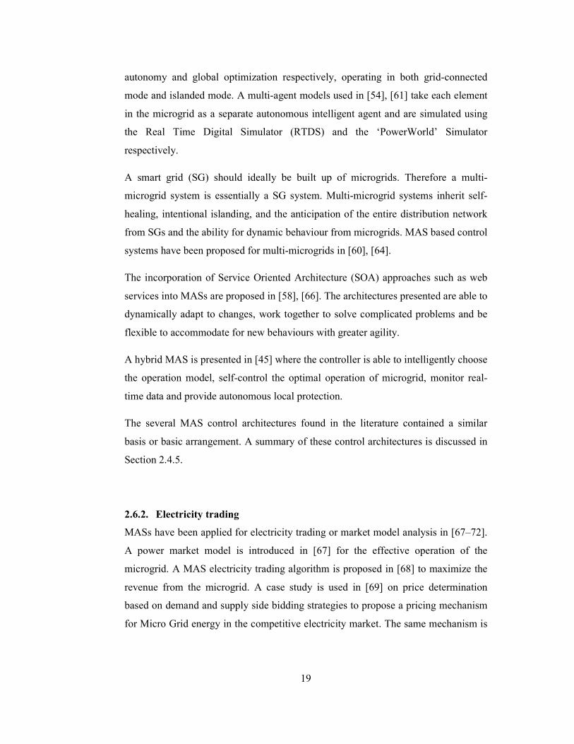
A summarization of the basic MAS structure used in distributed control approaches
in the literature is given in Figure 2.3. Three main agents shown are common in all
related work. A DG agent handles the addition, operation and control of all local DG
units. A user agent acts as or connects to a user interface where utility/consumer
users interact with the system. Last, but not least, a control agent will oversee all
these and any other related control tasks, while mainly connecting to/operating
circuit breakers. Two main types of control agents are seen; overall MAS controllers
[47], [50] and load controllers [53].
Figure 2.3 Basic multi agent system structure
This basic architecture can be implemented over a conceptual microgrid consisting of
several different DG units and critical and non-critical local loads as shown in Figure
2.4. Database agent facilitates message parsing (exchange) and storage, acting as the
access point for data for all the agents and users. Here the control agent is tasked
with islanding as well as load management.
Some drawbacks of the single layered architecture can be listed as:
• Certain agents get overloaded with objectives
• Such agents become critical, and their failure can be catastrophic
• Lower flexibility in terms of expanding the microgrid and/or controller

23
Figure 2.4 Single layered multi agent system architecture
24
3. CONCEPTUAL DESIGN OF DUAL-LAYERED MAS
This section presents the conceptual design of multi agent architecture in detail.
Step 2: Multi agent system architecture conceptual design
3.1. Dual layered architecture
The single layered multi agent systems have the drawback of agents needing cater
multiple objectives. This drawback can be overcome by properly delegating the
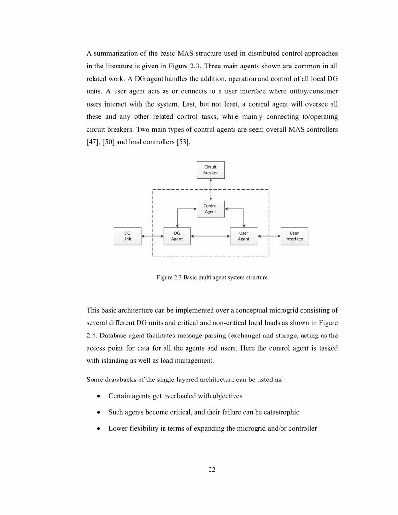
multiple objectives to different agents. The proposed multi agent architecture
achieves this task delegation by creating multi-layered multi agent system
architecture. This novel architecture is presented in Figure 4.1.
Figure 3.1 Proposed dual layered MAS architecture
The control hierarchy is split in to two, creating dual-layered control architecture.
The primary layer (or the strategic layer) comprises the Control agent who makes the
run-time decisions. The secondary (tactical) layer contains the User Agent, DG
Strategic (Primary) Level
Tactical (Secondary) Level
Utility (Background) Operations
� Makes run-time decisions
� Execution of run-time decisions
� I/O operations
� Stores, and shares data
� Data access point for all
agents
Control Agent
User Agent
DG Agent
LV Agent
Load Agent
DB Agent

25
Agent, LV Agent and Load Agent. This layer carries out the execution of the run-
time decisions of the strategic level, which mainly comprises input/output operations.
Both these layers are ultimately supported by a service (utility) provided by a DB
(Database) agent, running in the background. This utility agent stores system
information and data and messages shared between the agents and acts as a data
access point for all agents.
The agent assignment of the novel dual-layered architecture is given in Figure 3.2.
This introduces the new secondary control layer in comparison to the single layered
architecture given in Figure 2.3. The agents depicted in the figure are briefly
introduced in Section 3.2.
Figure 3.2 Interaction between agents in the dual layered multi agent architecture
The process of developing this dual-layered multi agent system and implementing it
on the simulation test-bed is given in Section 4. The different case studies carried out
and their respective results are given in Section 5.

26
3.2. Agents used in the dual-layered MAS
The proposed dual-layered MAS shown in Figure 3.2 comprise the control agent, LV
agent, Load agent, DG agent, User agent and DB agent:
Control agent: This agent monitors the main grid for faults and/or outages and
controls the secondary layer in the MAS. It oversees the operation of the secondary
layer which is tasked with handling loads and the low voltage (LV) connection. It
also informs the agents in the MAS whether the system is islanding capable or not.
Ultimately, the control agent will be the centre of the primary layer holding influence
over the DG agent and controlling the LV (Low Voltage) agent and Load agents.
LV agent: This agent controls the islanding operation by opening the circuit breaker
at the PCC. It stores the islanded or grid-connected status of the PCC. The LV agent
can also be given metering capabilities if a ‘net-metering’ scheme is used for the
microgrid.
Load agent: Each individual load has an individual load agent. It stores information
regarding each load and control the connect/disconnect operation. Information such
as load identification number, load priority and current demand are stored for each
load. The LV agent can also be given metering capabilities if DSM (Demand Side
Management) schemes are to be used within the microgrid.
DG agent: This agent is responsible for storing information regarding the DG unit,
metering and controlling the output and connecting/disconnecting the unit to/from
the microgrid. The information stored regarding the DG includes;
i. Identification number
ii. Connection status (connected/disconnected)
iii. Type of equipment (IC engine, micro-turbine, Solar PV, Fuel cell etc.)
iv. Rated power (in kW)
v. Output power (in kW)
vi. Local energy source (Fuel) availability (given as infinite)
vii. Unit availability (given as always available – not under maintenance)
viii. Energy cost (in Rs./kW)

27
User agent: This agent behaves as the gateway for the user to interact with the
system, to obtain real-time information and set system goals. This agent collects
information from other agents regarding demand and supply and makes it available
to the system users. The user agent can also interface with a GUI (Graphical User
Interface) for easy interaction.
Database Agent: stores system information and data and messages shared between
the agents. The priority list used for load management is also hosted by the database
agent. The database agent acts as the access point for data for all the agents and
users.
These agents operate collaboratively to achieve the overall goals of the system (i.e.
island the microgrid during a fault, protect supply to critical loads and provide
dynamic load management.)

28
4. IMPLEMENTATION OF DUAL-LAYERED MAS
Following section describes the process of implementing the dual-layered
architecture introduced in Section 3.1. The methods and process of developing and
implementing the dual-layered multi agent system using JADE is explained
including features of multi-agent systems and the JADE toolkit. This section also
describes the process of establishing TCP/IP communication for running the multi
agent system on the simulated test-bed.
Step 3: Developing the dual-layered multi agent system
4.1. Dual-layered Multi agent system implementation in JADE
The multi-agent system implementation using JADE can be broken into the
following main steps:
i. Agent specification
ii. Application analysis
iii. Application design
iv. Implementation
4.1.1. Agent specification
Here, the specifications, requirements and tasks for the agents in multi agent system
are defined. The agents to be used in the multi agent systems were introduced in
Section 3.2.
29
4.1.2. Application analysis
The operation of the multi agent system is defined in this step. The target is to
develop a multi agent system that achieves the objectives put forward in Section 1.3.
The MAS is expected to provide the following capabilities to the microgrid:
i. Dynamic interaction with the microgrid (Rapid islanding in case of an
upstream fault)
ii. Sharing limited capacity of local DG unit/s between multiple loads
iii. Load management and prioritization
In order for the agents to follow the objectives, how they collaborate with one
another must be clearly defined. The agent collaboration process is described below.
Agent collaboration
1 Main-grid / microgrid Stimulus control agent receives information from main
grid and microgrid
2 Respond to microgrid main Control agent responds the microgrid
3 Inform all agents control agent informs all registered subscribers
about the information from microgrid
4 Command loads sends control commands to its corresponding
loads
5 Command DG send control commands to the DG unit
6 Load information receives load information from their
corresponding loads
7 Control DG Power production control agent informs DG agent of how much
power to produce
8 Information on DG output
DG unit informs DG agent about the amount of
power produced
9 Manage loads control agent manages its corresponding load
circuitry based on locally produced power
30
4.1.3. Application design
Using the JADE toolkit to allow for agent to communication with each other and
reason about facts and knowledge in relation to the microgrid domain is carried out
by the following steps [1]:
i. Define an ontology including the schemas for the types of predicate, agent
action and concept that are pertinent to the microgrid domain.
ii. Develop proper Java classes for all types of predicate, agent action and
concept in the ontology.
iii. Register the defined ontology and the selected content language with the
agent.
iv. Create and handle content expression as Java objects that are instances of the
classes developed in step ii and let JADE translate these Java objects to/from
strings or sequences of bytes that fit the content slot of ACL Messages.
Details of the ontology creation and concept identification are discussed as the first
step in application design.

31
Ontology creation
The detailed structure of the ontology for the dual-layered MAS is given in Figure
4.1. The ontology, as an example, has a concept named LV (LV Agent), with a
predicate called Islanded (addressing whether grid connected or not) and an agent
action called Disconnect (to open the circuit breaker at PCC).
Figure 4.1 Dual-layered MAS ontology
Concepts can either be a role of an entity or a common property. Here the concepts
represent the agents that make up the multi agent system. A concept can include
subconcepts as shown in Figure 4.1 (i.e. the concept, Load, includes the subconcepts,
Load ID, Demand, Priority, and Connected).
Predicates house the status of different concepts that can either be true or false. Four
predicates are defined in the ontology; Islanded, Connected, SupplyGTDemand and

32
CapacityGTDemand. Islanded and Connected predicates are used by LV agent and
Load agents respectively to define the state of their circuit breakers as open or
closed. SupplyGTDemand verifies whether supply greater than or equal (>=) demand
in the case of controlling DG output during load management in islanded mode.
CapacityGTDemand is used for load shedding for load management to verify if the
available local capacity is greater than or equal to the total local demand.
Agent actions are special concepts that indicate actions that can be performed by
particular agents. For example, the agent actions, connect and disconnect are used by
LV and Load agents to close and open their circuit breakers.
Software based development of the ontology is specific to the toolkit and detailed
information regarding this process can be found in the online tutorial [43]. The
process consists of the following steps.
i. Define the vocabulary of the agents communication space
ii. Define the java class that specifies the structure and semantic of the object
MakeOperation ( )
iii. Define the schema of the object
iv. Register the ontology and the language that are used for assembling and
parsing (or coding and decoding) the content of messages with the agent's
content manager
33
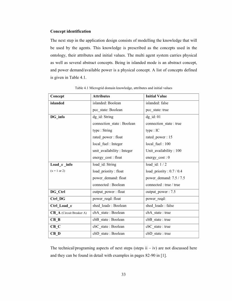
Concept identification
The next step in the application design consists of modelling the knowledge that will
be used by the agents. This knowledge is prescribed as the concepts used in the
ontology, their attributes and initial values. The multi agent system carries physical
as well as several abstract concepts. Being in islanded mode is an abstract concept,
and power demand/available power is a physical concept. A list of concepts defined
is given in Table 4.1.
Table 4.1 Microgrid domain knowledge, attributes and initial values
Concept Attributes Initial Value
islanded islanded: Boolean
pcc_state: Boolean
islanded: false
pcc_state: true
DG_info dg_id: String
connection_state : Boolean
type : String
rated_power : float
local_fuel : Integer
unit_availability : Integer
energy_cost : float
dg_id: 01
connection_state : true
type : IC
rated_power : 15
local_fuel : 100
Unit_availability : 100
energy_cost : 0
Load_x _info
(x = 1 or 2)
load_id: String
load_priority : float
power_demand: float
connected : Boolean
load_id: 1 / 2
load_priority : 0.7 / 0.4
power_demand: 7.5 / 7.5
connected : true / true
DG_Ctrl output_power : float output_power : 7.5
Ctrl_DG power_reqd: float power_reqd:
Ctrl_Load_x shed_loadx : Boolean shed_loadx : false
CB_A (Circuit Breaker A) cbA_state : Boolean cbA_state : true
CB_B cbB_state : Boolean cbB_state : true
CB_C cbC_state : Boolean cbC_state : true
CB_D cbD_state : Boolean cbD_state : true
The technical/programing aspects of next steps (steps ii – iv) are not discussed here
and they can be found in detail with examples in pages 82-90 in [1].

34
4.1.4. MAS algorithm implementation
The multi agent system implementation is discussed in this section. The multi agent
system allows the microgrid to operate in grid connected mode as well as islanded
mode. The multi agent system is implemented by developing the control algorithm
depicted below in Figure 4.2 .
Figure 4.2 Control algorithm for multi agent system operation
Assumptions: It is assumed that unlimited power is available from the grid and
local embedded generator has unlimited fuel to withstand an outage of any duration.
The embedded generator is assumed to be always online supplying part of the local
demand, and capable of instantly changing the output depending on changes in local
critical demand.

35
The control agent measures the main grid voltage and frequency, and detects any
fault or outage based on the measurements. If the measurements exceed the standard
thresholds in ±10% for voltage and ±0.5 Hz for frequency, the control agent switches
the microgrid to islanded mode operation. When the decision to switch to island
mode is taken, all the agents are notified and they cooperate and coordinate with the
control agent to achieve the objectives set forth. Based on the prescribed
MAS_Ontology, the agents can easily start their interactions and accomplish their
goals through the exchange of ACL messages. Three main objectives the multi agent
system has to meet (which are defined in Section 1.3) can be simplified as;
i. dynamic interaction with the microgrid (Rapid islanding in case of an
upstream fault)
ii. sharing limited capacity of local DG unit/s between multiple loads
iii. load management and securing supply based on load priority
Operation of each of the objectives is simulated and the success of the multi agent
system is verified in Section 5. The control algorithm is explained in detailed in the
respective simulation section.
36
Step 4: Integration of the multi agent system and the microgrid simulation
4.2. Running multi agent system application
The multi agent system attempts to control physical entities or a simulation of the
same. This puts the multi agent system and the simulation into two different
domains. In order for the multi agent system to work on the simulated environment
establishing communication between the two domains is required.
The multi agent system runs on a JAVA platform while the simulation is run on a
simulating environment (i.e. MATLAB/SIMULINK). Therefore, in order to establish
communication between two domains, for sensing and control TCP/IP is used. A
third party TCP/IP server [83] is utilized as an interface to MATLAB and it connects
to another middle server which allows multiple simultaneous TCP/IP connections.
Each agent requires a separate connection to the test-bed. The interface allows only a
single connection at a time; therefore a separate middle server is required. This
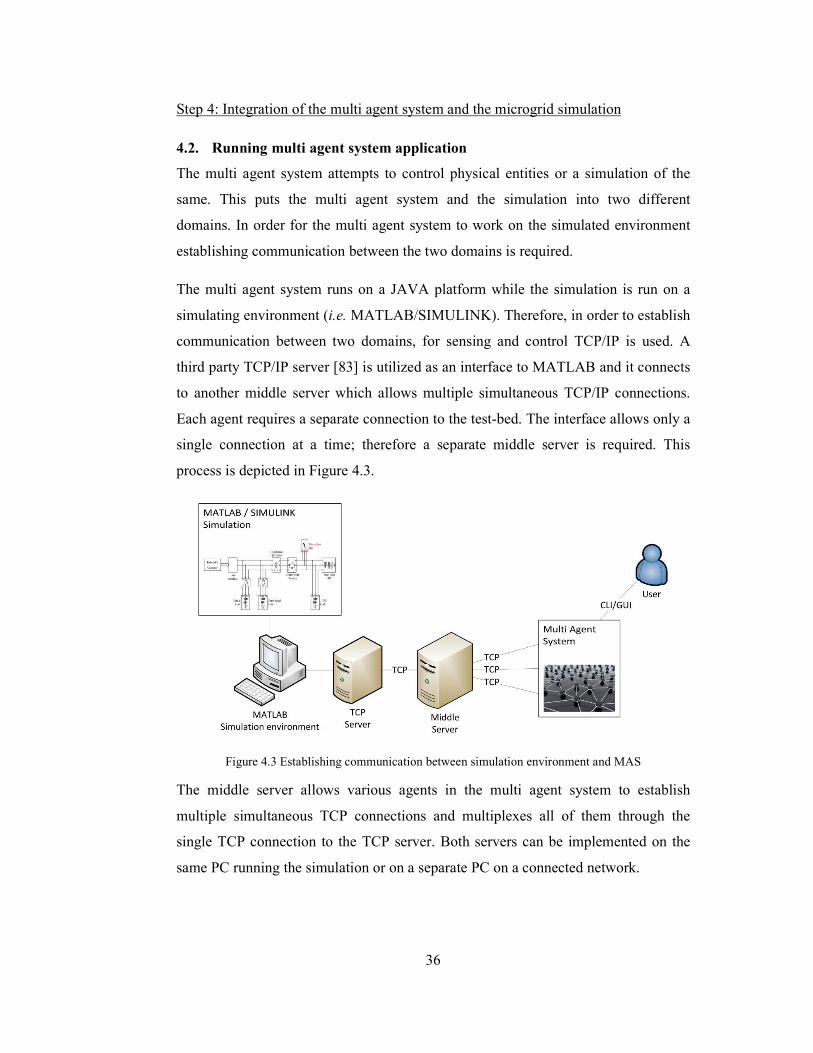
process is depicted in Figure 4.3.
Figure 4.3 Establishing communication between simulation environment and MAS
The middle server allows various agents in the multi agent system to establish
multiple simultaneous TCP connections and multiplexes all of them through the
single TCP connection to the TCP server. Both servers can be implemented on the
same PC running the simulation or on a separate PC on a connected network.

37
5. SIMULATIONS AND RESULTS
Step 5: Result validation using simulation studies
Three case studies are developed to verify the capability of the proposed MAS to
provide control and protection for an inverter based microgrid. Within conventional
power systems, frequency control is handled by rotating inertial masses of large
generators. This causes a problem within smaller microgrids. Therefore, an inverter
based system is selected, where the frequency control is handled by the inverter
interface. Details of the simulation test-bed used in the case studies are presented in
Section 5.1.
Case study 1: Intentional islanding during an upstream fault
In this case study, an upstream fault is introduced on the main grid system at 0.05 s
into the simulation. Upon the detection of the fault, the MAS switches from grid
connected mode to islanded mode of operation. The transition is carried out within
0.02 s of detecting the fault. This verifies the capability of the MAS in rapidly
initiating a seamless transition. This is further discussed in Section 5.2.
Case study 2: Protecting critical loads during intentional islanding
During an outage or fault on the main grid, the microgrid has to cater local demand
based solely on the local sources. In order to meet the local demand and maintain the
stability of the system at the same time, some loads have to be shed. This is done by,
shedding lower priority non-critical loads and protecting the higher priority critical
loads. This is completed within 0.02 s of detecting the fault and initiating islanding
transition. This verifies the capability of the MAS in rapidly protecting critical loads
during intentional islanding. This is further discussed in Section 5.3.
Case study 3: Managing critical loads during islanded operation
In the islanded mode, as the locally available DG capacity is limited, some of the
local loads have to be shed in order to maintain/protect the supply to higher priority
(critical) loads. During such islanded operation, if power needs to be re-routed to a
lower priority load by raising its priority, the MAS system allows for on-the-fly

38
priority revisions. This allows power to be re-connected to a previously shed load.
This is also completed within 0.02 s of detecting priority revision. This verifies the
capability of the MAS in rapidly managing load priorities during islanded operation.
This is further discussed in Section 5.4.
5.1. Description of simulation circuit
The simulations are carried out on an inverter-based microgrid test-bed developed
using MATLAB/SIMULINK. The test-bed is built mainly using the SimPower
Systems block set available in SIMULINK.
The test-bed based on the simplified block diagram, shown in Figure 5.1, is used for
the simulation case studies. The test-bed comprises an embedded generator, acting as
a DG unit, supplying part of the local demand, and some critical and non-critical
loads. It is assumed that the DG unit can operate at full capacity without fuel
limitations during any outage. It is also assumed that the DG unit can instantly
increase output using battery storage.
As an inverter based microgrid is considered, a grid interface unit comprising an
inverter, low pass filter, PWM (Pulse Width Modulation) and circuit breaker is used
in the case of a DC source. The microgrid is connected to a main utility grid (11 kV)
across a transformer (11kV/400V) and a main circuit breaker.
Figure 5.1 Simulated microgrid test-bed

39
5.2. Intentional islanding during a fault
The first case study is carried out to verify the effectiveness of the MAS in rapidly
islanding the microgrid upon the detection of an upstream outage on the main grid.
The ability of MAS to sense the upstream outage by detecting the voltage droop and
initiate agent actions to seamlessly transition to islanded mode from grid-connected
mode is addressed here. The test-bed used for the simulation is shown in Figure 5.2.
Figure 5.2 Test-bed set-up for case study 1
The test-bed comprises a 15kW DG unit producing 480V, connected to a 400V,
50Hz microgrid, a transformer (480V/400V) connecting the DG to the microgrid,
two 7.5kW local loads, with a connection to a 11kV main utility grid fed through
another transformer (11kV/400V), all of which are connected across circuit breakers.
Total local demand is 15 kW, 50% of which (7.5 kW) is supplied by the DG unit,
while the rest is supplied by the main grid. It is assumed that the DG unit can
instantly increase output using battery storage. An upstream fault is introduced to the
system at t = 0.05 s into the simulation. At the beginning of the simulation breakers
A, B, C and D are all closed.

40
5.2.1. Messages exchanged among agents and physical entities
The control agent detects the fault in the upstream, takes the strategic decision to
switch to island mode and informs the other agents to switch to islanded mode. The
control flow chart used in the process is given in Figure 5.3. This is a reduced
version of the algorithm given in Section 4.1.4. Upon receiving this ‘island’
command, the LV agent opens the main circuit breaker at PCC (point A) to isolate
the microgrid from the utility.
Figure 5.3 Control flow chart for intentional islanding
41
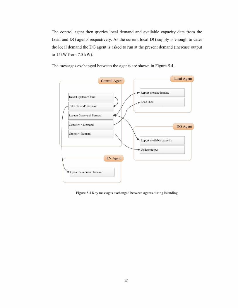
The control agent then queries local demand and available capacity data from the
Load and DG agents respectively. As the current local DG supply is enough to cater
the local demand the DG agent is asked to run at the present demand (increase output
to 15kW from 7.5 kW).
The messages exchanged between the agents are shown in Figure 5.4.
Figure 5.4 Key messages exchanged between agents during islanding

42
5.2.2. Updates to the ontology
The concepts known to the multi agent system is updated with every step. The agents
are able to identify the changes in the environment and react accordingly based on
these changes to the ontology. The updates to the ontology are:
Table 5.1 Updated concepts, initial and updated values for case study 1
Concept Initial Attribute/s Updated Value
islanded islanded: true
pcc_state: true
islanded: true
pcc_state: false
Load_1_info
load_id: 1
load_priority : 0.7
power_demand: 7.5
connected : true
load_id: 1
load_priority : 0.7
power_demand: 7.5
connected : true
Load_2_info
load_id: 2
load_priority : 0.4
power_demand: 7.5
connected : true
load_id: 2
load_priority : 0.4
power_demand: 7.5
connected : true
DG_Ctrl output_power : 15 output_power : 15
Ctrl_DG power_reqd: 15 power_reqd: 15
Ctrl_Load_1 shed_load1 : false shed_load1 : false
Ctrl_Load_2 shed_load2 : false shed_load2 : false
CB_A (Circuit Breaker A) cbA_state : true cbA_state : false

43
5.2.3. Results and discussion
The test-bed shown in Figure 5.2 is simulated for 0.1 s. The simulation results
presented in Figure 5.5 depicts the successful islanding process.
During grid connected mode:
While the microgrid is in grid-connected mode, the total demand is 15 kW. During
the grid-connected mode the DG unit only provides 7.5 kW output, 50% of the total
demand. Another 10 kW is required from the main grid to supply the microgrid. The
main grid experiences a fault at t = 0.5 s.
Figure 5.5 Line to line voltages during intentional islanding
During transition:
When the upstream outage is detected at t = 0.05 s the control agent informs the LV
agent and the Load agents to switch to island mode operation. Upon receiving the
islanding order the LV agent trips the main circuit breaker A, at the PCC, isolating
(a) Line to line voltage across the non-critical load at ‘A’, (b)
Line to line voltage at breaker ‘B’
(a) Main grid voltage supply
(b) Load voltage

44
the microgrid from the utility (Figure 5.5(a)). The Control agent then queries the DG
agent and the load agents regarding their available capacities the DG can provide to
the microgrid and the power requirements of the connected loads.
As the available maximum capacity of 15 kW is able to meet the total demand of 15
kW, the control agent commands the DG agent to increase DG output to match the
demand. Soon as the microgrid is put to island mode the supply to the loads are
maintained (see Figure 5.5(b)).
Islanded mode:
At t=0.05s the microgrid is separated from the main grid and the local loads are
secured. After the microgrid switches to island mode the total local demand is met by
the DG unit by supplying 15 kW.
All agent operations are carried out rapidly, from detecting fault, opening the main
breaker, connecting the local source and shedding loads, to stabilize the microgrid
within 0.02 s. Therefore the system is able to disconnect from the main utility grid
and maintain the supply to the critical loads without suffering a brownout and/or
blackout.

45
5.3. Protecting critical loads during intentional islanding
The second case study addresses the capability of the MAS to protect/secure power
to critical loads during intentional islanding. This should happen immediately
following the transition to islanded mode. If power supply from available local DG
unit is limited and insufficient to supply the total local demand, load shedding has to
be carried out rapidly in order to secure supply to the most critical loads. The test-
bed used for the simulation is shown in Figure 5.6.
Figure 5.6 Test-bed set-up for case study 2
The test-bed is same as the one used in case study 1, with only the following
changes. Two local loads are 15 kW each with assigned priorities of 0.7 and 0.4
respectively. The total local demand is 30 kW; initially the DG unit supplies 10 kW
while the other 20 kW is provided from the main grid. Similar to case study 1, an
upstream fault is introduced to the system at t = 0.05 s in to the simulation. At the
beginning of the simulation breakers A, B, C and D are all closed.

46
5.3.1. Messages exchanged among agents and physical entities
The control process and messages exchanged between agents are based on the details
given in Section 5. Further details regarding the control process can be found in
Figure 5.3. Messages exchanged between the agents are as shown in Figure 5.4. As
the local DG unit is unable to meet the total demand, load shedding is initialized
based on the assigned priorities. This makes load connected to point C with the
higher priority, the critical load. Therefore, a load_shed command is issued to the
load agent for the lower priority, non-critical load at point D.
5.3.1. Updates to the ontology
The concepts known to the multi agent system is updated with every step. The agents
are able to identify the changes in the environment and react accordingly based on
these changes to the ontology. The updates to the ontology are:
Table 5.2 Updated concepts, initial and updated values for case study 2
Concept Initial Value Updated Value
islanded islanded: false
pcc_state: true
islanded: true
pcc_state: false
Load_1_info
load_id: 1
load_priority : 0.7
power_demand: 15
connected : true
load_id: 1
load_priority : 0.7
power_demand: 15
connected : true
Load_2_info
load_id: 2
load_priority : 0.4
power_demand: 15
connected : true
load_id: 2
load_priority : 0.4
power_demand: 15
connected : false
DG_Ctrl output_power : 10 output_power : 15
Ctrl_DG power_reqd: 10 power_reqd: 15
Ctrl_Load_1 shed_load1 : false shed_load1 : false
Ctrl_Load_2 shed_load2 : false shed_load2 : true
CB_A (Circuit Breaker A) cbA_state : true cbA_state : false
CB_D cbD_state : true cbD_state : false

47
5.3.2. Results and discussion
The test-bed shown in Figure 5.6 is simulated for 0.12 s. The simulation results
shown in Figure 5.7 depict the successful islanding and subsequent securing of
critical loads.
Grid connected mode:
While the microgrid is in grid-connected mode, the total demand is 30 kW, with 15
kW critical loads and 15 kW non-critical loads. During the grid-connected mode the
DG unit provides 10 kW output and the other 20 kW is provided by the main grid.
The main grid experiences a fault at t = 0.5 s.
Transition period:
When the upstream outage is detected at t = 0.05 s the control agent informs the LV
agent and the Load agents to switch to island mode operation. Upon receiving the
islanding order the LV agent trips the main circuit breaker A, at the PCC, isolating
the microgrid from the utility (Figure 5.7(a)). The control agent then queries the DG
agent and the load agents regarding their available capacities that the DG can provide
to the microgrid and the power requirements of the connected loads.
As the total load of 30 kW exceeds the available maximum capacity of 15 kW, the
control agent commands the load agents to shed the 15 kW non-critical loads to
match the DG capacity and the DG unit to increase output to 15 kW. Soon as the
microgrid is put to island mode the supply to the critical loads is maintained (see
Figure 5.7(b)). The load agent at the non-critical loads sheds them from the system
by opening breaker D (see Figure 5.7(c)).
Islanded mode:
At t=0.05s the microgrid is separated from the main grid and the load agents balance
the local demand. After the microgrid switches to island mode the total local demand
is met by the embedded generator supplying 15 kW.

48
Figure 5.7 Line to line voltages during securing critical loads
All agent operations are carried out rapidly; from detecting fault, opening the main
breaker, connecting the local source and shedding loads, to stabilize the microgrid
within 0.02 s. Therefore the system is able to disconnect from the main utility grid
and maintain the supply to the critical loads without suffering a brownout and/or
blackout.
(a) Line to line voltage across the non-critical load at ‘A’, (b) Line
to line voltage at breaker ‘C’, (c) Line to line voltage at breaker ‘D’
(a) Main grid voltage supply
(b) Critical load voltage
(c) Non-critical load voltage

49
5.4. Managing critical loads during islanded operation
The third case study addresses the capability of the MAS to provide load
management capabilities during islanded operation. As the available local capacity is
limited and insufficient to cater total local demand during islanded mode, non-critical
(lower priority) loads have to be dynamically shed in order to protect the stability of
the microgrid. This simulation shows the ability of the MAS to allow for dynamic
update of load priority levels. The test-bed used for the simulation is shown in Figure
5.8.
Figure 5.8 Test-bed set-up for case study 3
The same test-bed used in Section 5.3 is used to simulate case study 3. The local
loads are given two priority levels as shown in Figure 5.8. Local load 01 is given a
priority level of 0.7, and load 02 is given a priority level is 0.4. This initial setting
designates load 01 as a higher priority load while load 02 is considered a lower
priority, by their respective load agents. At the beginning of the simulation breakers
A, B, C and D are all closed. An upstream fault is introduced to the system at t = 0.05
s into the simulation, and the microgrid switches to islanded operation. During
islanded operation the load 02 priority is raised to 0.9 at t = 0.14s.

50
5.4.1. Messages exchanged among agents and physical entities
The objective of the test setup is to demonstrate the ability of the proposed MAS to
island the microgrid after an upstream fault is detected, and maintain supply to the
most critical loads with dynamic priorities. The control flow chart used in the process
is given in Figure 5.9.
Figure 5.9 Control flow chart for load management during islanded operation
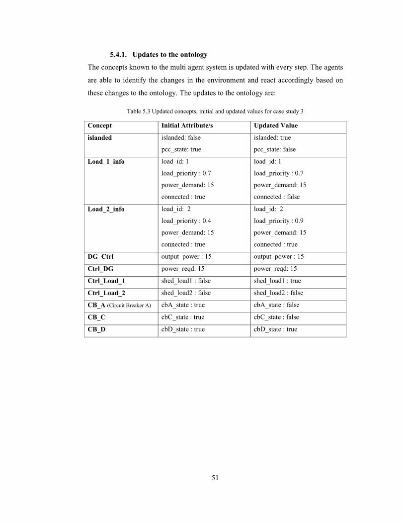
51
5.4.1. Updates to the ontology
The concepts known to the multi agent system is updated with every step. The agents
are able to identify the changes in the environment and react accordingly based on
these changes to the ontology. The updates to the ontology are:
Table 5.3 Updated concepts, initial and updated values for case study 3
Concept Initial Attribute/s Updated Value
islanded islanded: false
pcc_state: true
islanded: true
pcc_state: false
Load_1_info
load_id: 1
load_priority : 0.7
power_demand: 15
connected : true
load_id: 1
load_priority : 0.7
power_demand: 15
connected : false
Load_2_info
load_id: 2
load_priority : 0.4
power_demand: 15
connected : true
load_id: 2
load_priority : 0.9
power_demand: 15
connected : true
DG_Ctrl output_power : 15 output_power : 15
Ctrl_DG power_reqd: 15 power_reqd: 15
Ctrl_Load_1 shed_load1 : false shed_load1 : true
Ctrl_Load_2 shed_load2 : false shed_load2 : false
CB_A (Circuit Breaker A) cbA_state : true cbA_state : false
CB_C cbC_state : true cbC_state : false
CB_D cbD_state : true cbD_state : true

52
5.4.2. Results and discussion
The test-bed shown in Figure 5.8 is simulated for 0.2 s. the simulation results shown
in Figure 5.10 depict the successful islanding and subsequent securing of critical
loads.
Initially the microgrid is operating in the grid-connected mode, with the embedded
generator is supplying only part of the local loads while the rest is supplied by the
utility grid. The demands supplied initially by the DG and the grid are depicted in
Figure 5.8.
Figure 5.10 Line to line voltages during islanded operation
(a) Main grid voltage at breaker ‘A’, (b) load 01 measured
at ‘C’: switches from high priority to low priority, (c) load
02 measured at ‘D’: switches from low priority to high
priority.

53
Grid connected mode:
While the microgrid is in grid-connected mode, the total demand is 30 kW,
comprising two 15 kW local loads. During the grid-connected mode the embedded
generator only provides 10 kW, while the other 20 kW is supplied by the main grid
to the microgrid.
Transition period:
The proposed dual layered MAS is able to successfully island the microgrid during
the upstream outage within 0.02 s of detecting the fault in the main utility grid. As
the local generation capacity is unable to meet the total local demand, the MAS
initiates load shedding upon initially set priority levels of the loads as in case study 2
(see Section 5.3). This enables the MAS to maintain supply to the most critical load,
load 01, by shedding the least critical load, load 02.
Islanded mode:
At t = 0.05 s the microgrid is separated from the main grid and the load agents
balance the local demand as in case study 2 (see Section 5.3). After the microgrid
switches to island mode the total local demand is met by the embedded generator
supplying 15 kW.
During the island operation, the user agent can revise the initial priority assignment.
This can be pre-initiated or a user can change the priorities during the islanded mode.
At t=0.14, the user agent revises the priority value of load 02 from p=0.4 to p=0.9
and communicates the revise_request to the load agent at load 02. This update is
forwarded to other agents via the directory agent, and the control agent reinitiates
load management procedures. As the DG unit is still unable to meet the total demand
of 30 kW, and has to shed non-critical (lower priority) loads to maintain power to the
new highest priority load, load 02.
Therefore, the control agent commands the load agents to shed the load 01 of 25 kW
to match the DG capacity. Thus, the supply to the new most critical load, load 02 is

54
provided by re-closing ‘D’ (see Figure 5.10(c)). The load agent at the new lower
priority load, load 01, sheds it from the system by opening breaker ‘C’ (see Figure
5.10(b)). This process is shown in Table 5.4.
Table 5.4 Priority revision during islanded mode
Grid Connected mode Islanded mode
Initial priority Revised priority
Load 01 Priority = 0.7
Connected
Priority = 0.7
Connected
Priority = 0.7
Disconnected
Load 02 Priority = 0.4
Connected
Priority = 0.4
Disconnected
Priority = 0.9
Connected
When the load priorities are revised by a user via the user agent, the MAS is able to
reconfigure the system, in order to provide power to the new most critical load. The
reconfiguration is also done within 0.02 s of the revision and successfully reconnects
the new critical load. The results show the capability of the MAS to safely island and
maintain the supply to its critical loads, while allowing for the critical loads to be
dynamically revised.

55
6. CONCLUSIONS AND FUTURE DIRECTIONS
6.1. Conclusions
The developed MAS based control architecture for control and protection of an
inverter based microgrid has been successfully verified using a simulated microgrid
test-bed in MATLAB/SIMULINK. The MAS has been developed using the JADE
platform using its available programming techniques and communication facilities.
The control system has been endowed with seamless islanding, protection of critical
loads and load management capabilities during islanded operation.
Existing MAS based controllers for microgrid applications relied on a single layered
architecture which tasked agents with multiple objectives. This drawback was
overcome by developing novel dual layered architecture, where all tasks were
properly delegated to individual agents.
The MAS controller development phase involved application specification, analysis,
design and implementation. This process created the agents that sense the changes in
the environment and take initiative to achieve the overall goal put before them. This
was achieved by creation of five main agents; control agent, user agent, DG agent,
LV agent and load agent. These agents were supported by the DB agent running in
the background. The agents were then connected to a simulated microgrid test-bed in
MATLAB/SIMULINK over a third party TCP/IP server. Information regarding
agent development and server implementation has been discussed. The MAS
controller was simulated on a test-bed to demonstrate its ability to seamlessly island
the microgrid upon the detection of an upstream fault, protect critical loads during
islanding and manage critical and non-critical loads during islanded operation.
This incursion into multi agent based control system development will act as a
stepping stone to develop more intelligent distributed control systems in the future.
The novel concept of multi–layered control architectures will increase the impact
MAS has in microgrid control.
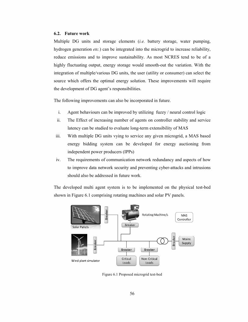
56
6.2. Future work
Multiple DG units and storage elements (i.e. battery storage, water pumping,
hydrogen generation etc.) can be integrated into the microgrid to increase reliability,
reduce emissions and to improve sustainability. As most NCRES tend to be of a
highly fluctuating output, energy storage would smooth-out the variation. With the
integration of multiple/various DG units, the user (utility or consumer) can select the
source which offers the optimal energy solution. These improvements will require
the development of DG agent’s responsibilities.
The following improvements can also be incorporated in future.
i. Agent behaviours can be improved by utilizing fuzzy / neural control logic
ii. The Effect of increasing number of agents on controller stability and service
latency can be studied to evaluate long-term extensibility of MAS
iii. With multiple DG units vying to service any given microgrid, a MAS based
energy bidding system can be developed for energy auctioning from
independent power producers (IPPs)
iv. The requirements of communication network redundancy and aspects of how
to improve data network security and preventing cyber-attacks and intrusions
should also be addressed in future work.
The developed multi agent system is to be implemented on the physical test-bed
shown in Figure 6.1 comprising rotating machines and solar PV panels.
Figure 6.1 Proposed microgrid test-bed
57
REFERENCES
[1] F. L. Bellifemine, G. Caire, and D. Greenwood, Developing Multi-Agent Systems
with JADE (Wiley Series in Agent Technology). John Wiley & Sons, 2007.
[2] L. Martinez-Lopez and F. J. Martinez-Lopez, “Intelligent e-services and multi-
agent systems for B2C e-commerce,” Internet Research, vol. 20, no. 3, Aug.
2010.
[3] M. Wissner, “ICT, growth and productivity in the German energy sector - On the
way to a smart grid?,” Utilities Policy, vol. 19, no. 1, pp. 14–19, 2011.
[4] The NETL Smart Grid Implementation Strategy (SGIS). [Online]. Available:
http://www.netl.doe.gov/smartgrid/. [Accessed: 25-Oct-2010].
[5] C.W. Gellings, The Smart Grid: Enabling Energy Efficiency and Demand
Response. Fairmont Press, 2009.
[6] R. H. Lasseter and P. Paigi, “Microgrid: a conceptual solution,” in Proc. 2004
IEEE 35th Annu. Power Electronics Specialists Conf., PESC 04. 2004, vol. 6, pp.
4285– 4290.
[7] R. Zamora, A. K. Srivastava, and Syukriyadin, “Microgrids for Reliable, Clean,
and Efficient Power Delivery,” in Proc. Annu. Int. Workshop and Expo on
Sumatera Tsunami, AIWEST 2009, Banda Aceh, 2009.
[8] N. Jenkins, Embedded Generation. The Institution of Engineering and
Technology, Michael Faraday House, Six Hills Way, Stevenage SG1 2AY, UK:
IET, 2000.
[9] RSView32 from Rockwell Software. [Online]. Available:
http://www.rockwellautomation.com/rockwellsoftware/performance/view32/.
[Accessed: 17-Jan-2011].
[10] JADE, “Jade - Java Agent DEvelopment Framework.” [Online]. Available:
http://jade.cselt.it/. [Accessed: 01-Nov-2010].

58
[11]Zeus agent development toolkit. [Online]. Available:
http://labs.bt.com/projects/agents/zeus. [Accessed: 01-Nov-2010].
[12] J. Lu, G. Chen, and X. Yu, “Modelling, analysis and control of multi-agent
systems: A brief overview,” in Proc. 2011 IEEE Int. Symp. Circuits and Systems,
ISCAS, 2011, pp. 2103–2106.
[13] Z. Li et al., “Consensus of Multiagent Systems and Synchronization of Complex
Networks: A Unified Viewpoint,” IEEE Trans. Circuits and Syst. I, Reg. Papers,
vol. 57, no. 1, pp. 213–224, Jan, 2010.
[14] G. Acampora, V. Loia, and M. Gaeta, “Exploring e-Learning Knowledge
Through Ontological Memetic Agents,” IEEE Comput. Intell. Mag., vol. 5, no. 2,
pp. 66–77, May 2010.
[15]Z. Meng et al., “Leaderless and Leader-Following Consensus With
Communication and Input Delays Under a Directed Network Topology,” IEEE
Trans. Syst. Man Cybern. B, Cybern., vol. 41, no. 1, pp. 75–88, Feb, 2011.
[16] E. Semsar-Kazerooni and K. Khorasani, “Optimal Consensus Seeking in a
Network of Multiagent Systems: An LMI Approach,” IEEE Trans. Syst. Man
Cybern. B, Cybern., vol. 40, no. 2, pp. 540–547, Apr. 2010.
[17] M. S. R. Mousavi, M. Khaghani, and G. Vossoughi, “Collision avoidance with
obstacles in flocking for multi agent systems,” in Proc. 2010 Int. Conf. Industrial
Electronics, Control & Robotics, IECR, 2010, pp. 1–5.
[18] W. Lepuschitz et al., “Implementation of automation agents for batch process
automation,” in Proc. 2010 IEEE Int. Conf. Industrial Technology, ICIT, 2010,
pp. 524–529.
[19] J. Barbosa and P. Leitao, “Modelling and simulating self-organizing agent-based
manufacturing systems,” in Proc. 2010 36th Annu. Conf. IEEE Industrial
Electronics Society, IECON, pp. 2702–2707.
[20] Q. Dong et al., “Multi-agent based federated control of large-scale systems with
application to ship roll control,” in Proc. 2011 4th Int. Symp. Resilient Control
Systems, ISRCS, 2011, pp. 142–147.

59
[21] S. Tan et al., “Research on continuous rolling process control system based on
multi-agent,” in Proc. 2011 9th World Congr. Intelligent Control and
Automation, WCICA, 2011, pp. 75–78.
[22] R. Claes, T. Holvoet, and D. Weyns, “A Decentralized Approach for
Anticipatory Vehicle Routing Using Delegate Multiagent Systems,” IEEE Trans.
Intell. Transp. Syst., vol. 12, no. 2, pp. 364–373, Jun. 2011.
[23] B. Chen and H. H. Cheng, “A Review of the Applications of Agent Technology
in Traffic and Transportation Systems,” IEEE Trans. Intell. Transp. Syst., vol.
11, no. 2, pp. 485–497, Jun. 2010.
[24] B. P. Gokulan and D. Srinivasan, “Distributed Geometric Fuzzy Multiagent
Urban Traffic Signal Control,” IEEE Trans. Intell. Transp. Syst., vol. 11, no. 3,
pp. 714–727, Sep. 2010.
[25] K. T. Seow and D. Lee, “Performance of Multiagent Taxi Dispatch on
Extended-Runtime Taxi Availability: A Simulation Study,” IEEE Trans. Intell.
Transp. Syst., vol. 11, no. 1, pp. 231–236, Mar. 2010.
[26] Aglets agent development toolkit. [Online]. Available:
http://aglets.sourceforge.net. [Accessed: 01-Nov-2010].
[27] Voyager agent development toolkit. [Online]. Available:
htt://www.recursionsw.com. [Accessed: 01-Nov-2010].
[28] Tracy agent development toolkit. [Online]. Available: http://www.mobile-
agents.org. [Accessed: 27-Jun-2011].
[29] Springs agent development toolkit. [Online]. Available:
http://sid.cps.unizar.es/SPRINGS. [Accessed: 01-Nov-2010].
[30] D. Camacho et al., “Agent architecture for intelligent gathering system,” AI
Communications, vol. 18, no. 1, pp. 15–32, Jan. 2005.
[31] D. Camacho and R. Aler, “Software and Performance measures for evaluating
multi-agent frameworks,” Applied Artificial Intelligence, vol. 19, no. 6, pp. 645–
657, 2005.
60
[32] E. Shakshuki and Y. Jun, Multi-agent Development Toolkits: An Evaluation.
Springer Berlin/Heidelberg, 2004.
[33] R. Trillo, S. Ilarri, and E. Mena, “Comparison and Performance Evaluation of
Mobile Agent Platforms,” in Proc. 3rd Int. Conf. Autonomic and Autonomous
Systems, ICAS07, Athens, Greece, 2007.
[34] D. Camacho et al., “Performance evaluation of Zeus, JADE and SkeletonAgent
Framework,” in Proc. IEEE Int. Conf. Systems, Man and Cybernetics, vol. 4, no.
6, p. 2002.
[35] M. K. Perdikeas et al., “Mobile agent standards and available platforms,”
Computer Networks, vol. 31, no. 19, pp. 1999–2016, Aug. 1999.
[36] M.D. Dikaiakos and G. Samaras, “Performance evaluation of mobile agents:
Issues and approaches,” in Lecture notes in computer science, vol. 2047,
Springer-Verlag, pp. 148–166.
[37] A. R. Silva et al., “Towards a reference model for surveying mobile agent
systems,” Autonomous Agents and Multi-Agent Systems, vol. 4, no. 3, pp. 187–
231, Sep. 2001.
[38] E. Shakshuki, “A methodology for evaluating agent toolkits,” in Proc. IEEE Int.
Conf. on Information Technology: Coding and Computing, ITCC, 2005, pp. 391–
396.
[39] IEEE FIPA, Foundation for Intelligent Physical Agents. [Online]. Available:
http://www.fipa.org/. [Accessed: 14-Jan-2011].
[40] Jade tutorial: Jade programming for beginners, 2009. [Online]. Available:
http://jade.tilab.com/doc/tutorials/JADEProgramming-Tutorial-for-
beginners.pdf.
[41] F. Bellifemine, A. Poggi, and G. Rimassa, “Developing Multi-agent Systems
with JADE,” in Proc. 7th Int. Workshop on Intelligent Agents VII. Agent
Theories Architectures and Languages, London, UK, 2001, pp. 89–103.
[42] Event Handlers and Callback Functions. [Online]. Available:
http://w3future.com/html/stories/callbacks.xml. [Accessed: 29-Jan-2012].
61
[43] J. Vaucher and A. Ncho, “Jade Primer and Tutorial,” Apr-2004. [Online].
Available: http://www.iro.umontreal.ca/~vaucher/Agents/Jade/JadePrimer.html.
[Accessed: 29-Nov-2010].
[44] C.-X. Dou et al., “Multi-Agent Based Control Framework for Microgrids,” in
Proc. 2009 Asia-Pacific Power and Energy Engineering Conf., Wuhan, China,
2009, pp. 1–4.
[45] X. Zhou et al., “Hybrid operation control method for micro-grid based on
MAS,” in Proc. 2010 IEEE Int.Conf. Progress in Informatics and Computing,
Shanghai, China, 2010, pp. 72–75.
[46] Z. Jiang, “Agent-Based Control Framework for Distributed Energy Resources
Microgrids,” in 2006 IEEE/WIC/ACM Int. Conf. Intelligent Agent Technology,
IAT'06, Hong Kong, China, 2006, pp. 646–652.
[47] A. L. Dimeas and N. D. Hatziargyriou, “Operation of a Multiagent System for
Microgrid Control,” IEEE Trans. Power Syst., vol. 20, no. 3, pp. 1447–1455,
Aug. 2005.
[48] M. Cirrincione et al., “Intelligent energy management system,” in Proc. 7th
IEEE Int. Conf. Industrial Informatics, Cardiff, Wales, UK, 2009, pp. 232–237.
[49] N. Cai and J. Mitra, “A decentralized control architecture for a microgrid with
power electronic interfaces,” in Proc. North American Power Symp. 2010,
Arlington, TX, USA, 2010, pp. 1–8.
[50] A. L. Dimeas and N. D. Hatziargyriou, “A MAS Architecture for Microgrids
Control,” in Proc.13th Int. Conf. Intelligent Systems Application to Power
Systems, Arlington, Virginia, USA, 2005, pp. 402–406.
[51] W. Zheng and J. Cai, “A multi-agent system for distributed energy resources
control in microgrid,” in Proc.2010 5th Int. Conf. Critical Infrastructure, CRIS,
Beijing, China, 2010, pp. 1–5.
[52] C. M. Colson and M. H. Nehrir, “A review of challenges to real-time power
management of microgrids,” in Proc. 2009 IEEE Power & Energy Society
General Meeting, Calgary, Canada, 2009, pp. 1–8.
62
[53] A. L. Dimeas and N. D. Hatziargyriou, “Agent based Control for Microgrids,” in
Proc. 2007 IEEE Power Engineering Society General Meeting, Tampa, FL,
USA, 2007, pp. 1–5.
[54] H. N. Aung et al., “Agent-based intelligent control for real-time operation of a
microgrid,” in Proc. 2010 Joint Int. Conf. Power Electronics, Drives and Energy
Systems & 2010 Power India, New Delhi, India, 2010, pp. 1–6.
[55] T. Li et al., “Control system simulation of microgrid based on IP and Multi-
Agent,” in Proc. 2010 Int. Conf. Information, Networking and Automation ,
ICINA, Kunming, China, 2010, pp. V1–235–V1–239.
[56] S. J. Chatzivasiliadis, N. D. Hatziargyriou, and A. L. Dimeas, “Development of
an agent based intelligent control system for microgrids,” in Proc. 2008 IEEE
Power and Energy Society General Meeting - Conversion and Delivery of
Electrical Energy in the 21st Century, Pittsburgh, PA, USA, 2008, pp. 1–6.
[57] T. Funabashi et al., “Field Tests of a Microgrid Control System,” in Proc. 41st
International Universities Power Engineering Conf., Newcastle upon Tyne, UK,
2006, pp. 232–236.
[58] D. A. Cohen, “GridAgentTM
: Intelligent agent applications for integration of
distributed energy resources within distribution systems,” in Proc. 2008 IEEE
Power and Energy Society General Meeting - Conversion and Delivery of
Electrical Energy in the 21st Century, Pittsburgh, PA, USA, 2008, pp. 1–5.
[59] J. Rocabert et al., “Intelligent control agent for transient to an island grid,” in
Proc. 2010 IEEE Int.Symp. Industrial Electronics, Bari, Italy, 2010, pp. 2223–
2228.
[60] G. Zheng and N. Li, “Multi-Agent Based Control System for Multi-Microgrids,”
in Proc. 2010 Int. Conf. Computational Intelligence and Software Engineering,
Wuhan, China, 2010, pp. 1–4.
[61] T. Logenthiran, D. Srinivasan, and D. Wong, “Multi-agent coordination for DER
in MicroGrid,” in Proc. 2008 IEEE Int. Conf. Sustainable Energy Technologies,
Singapore, Singapore, 2008, pp. 77–82.

63
[62] A. L. Dimeas and N. D. Hatziargyriou, “Multi-agent reinforcement learning for
microgrids,” in Proc. IEEE Power and Energy Society General Meeting,
Minneapolis, MN, 2010, pp. 1–8.
[63] M. Pipattanasomporn, H. Feroze, and S. Rahman, “Multi-agent systems in a
distributed smart grid: Design and implementation,” in Proc. 2009 IEEE/PES
Power Systems Conf. Expo., Seattle, WA, USA, 2009, pp. 1–8.
[64] E. J. Ng and R. A. El-Shatshat, “Multi-microgrid control systems (MMCS),” in
Proc. IEEE Power and Energy Society General Meeting, Minneapolis, MN,
2010, pp. 1–6.
[65] Z. Jian et al., “The application of multi agent system in microgrid coordination
control,” in Proc. 2009 Int. Conf. Sustainable Power Generation and Supply,
Nanjing, 2009, pp. 1–6.
[66] H. J. Zhou et al., “The architecture of intelligent distribution network based on
MAS-SOA,” in Proc. IEEE Power and Energy Society General Meeting,
Minneapolis, MN, 2010, pp. 1–6.
[67] H.-M. Kim and T. Kinoshita, “Multiagent system for Microgrid operation based
on power market environment,” in Proc. 31st Int. Telecommunications Energy
Conf., INTELEC 2009, Incheon, South Korea, 2009, pp. 1–5.
[68] T. Funabashi et al., “An autonomous agent for reliable operation of power
market and systems including microgrids,” in Proc. 2008 3rd Int. Conf. Electric
Utility Deregulation and Restructuring and Power Technologies, Nanjing,
China, 2008, pp. 173–177.
[69] A. K. Basu et al., “Key energy management issues of setting market clearing
price (MCP) in micro-grid scenario,” in Proc. 2007 42nd Int.Universities Power
Engineering Conf., Brighton, UK, 2007, pp. 854–860.
[70] A. Sinha et al., “Setting of market clearing price (MCP) in microgrid power
scenario,” in Proc. 2008 IEEE Power and Energy Society General Meeting -
Conversion and Delivery of Electrical Energy in the 21st Century, Pittsburgh,
PA, USA, 2008, pp. 1–8.
64
[71] R. Duan and G. Deconinck, “Multi-agent coordination in market environment
for future electricity infrastructure based on microgrids,” in Proc. 2009 IEEE Int.
Conf. Systems, Man and Cybernetics, San Antonio, TX, USA, 2009, pp. 3959–
3964.
[72] R. Duan and G. Deconinck, “Multi-agent model and interoperability of a market
mechanism of the Smart Grids,” in Proc. 2010 IEEE/IFIP Network Operations
and Management Symp. Workshops, Osaka, Japan, 2010, pp. 312–315.
[73] I. Maity and S. Rao, “Simulation and Pricing Mechanism Analysis of a Solar-
Powered Electrical Microgrid,” IEEE Syst. J., vol. 4, no. 3, pp. 275–284, Sep.
2010.
[74] T. Logenthiran et al., “Multi-Agent System (MAS) for short-term generation
scheduling of a microgrid,” in Proc. 2010 IEEE Int. Conf. Sustainable Energy
Technologies, ICSET, Kandy, Sri Lanka, 2010, pp. 1–6.
[75] R. Bhuvaneswari et al., “Intelligent agent based auction by economic generation
scheduling for microgrid operation,” in Proc. 2010 Innovative Smart Grid
Technologies, ISGT, Gaithersburg, MD, USA, 2010, pp. 1–6.
[76] T. Logenthiran et al., “Scalable Multi-Agent System (MAS) for operation of a
microgrid in islanded mode,” in Proc. 2010 Joint Int.Conf. Power Electronics,
Drives and Energy Systems & 2010 Power India, New Delhi, India, 2010, pp. 1–
6.
[77] X. Yuqin, Z. Li, and W. Zengping, “Research on service restoration for large
area blackout of distribution system with distributed generators,” in Proc. 2009
International Conference on Sustainable Power Generation and Supply,
Nanjing, 2009, pp. 1–6.
[78] Peng Li et al., “Multi-agent approach for service restoration of microgrid,” in
Proc. 2010 5th IEEE Conf. Industrial Electronics and Applications, Taichung,
Taiwan, 2010, pp. 962–966.
[79] Y. Xu and W. Liu, “Novel Multiagent Based Load Restoration Algorithm for
Microgrids,” IEEE Trans. Smart Grid, vol. 2, no. 1, pp. 152–161, Mar. 2011.

65
[80] X. D. Li, Y. Q. Xu, and L. Zhang, “Distribution service restoration with DGs
based on multi-agent immune algorithm,” in Proc. 2009 2nd Int. Conf. Power
Electronics and Intelligent Transportation System, PEITS, Shenzhen, China,
2009, pp. 1–4.
[81] R. Olfati-Saber, J. A. Fax, and R. M. Murray, “Consensus and cooperation in
networked multi-agent systems,” Proc. IEEE, vol. 95, no. 1, pp. 215–233, 2007.
[82] W. Ren, R. W. Beard, and E. M. Atkins, “A survey of consensus problems in
multi-agent coordination,” in Proc. 2005 American Control Conf., 2005, pp.
1859–1864.
[83] W. Zimmermann, IOlib – Hardware input / output library module for matlab and
simulink, 2011. [Online]. Available: http://www.it.hs-
esslingen.de/~zimmerma/software/index_uk.html.