Embed Size (px)
Citation preview
Doc. # OIPB-C15010 Orig. Rel. – 08/2020
Curr. Rev. - 00
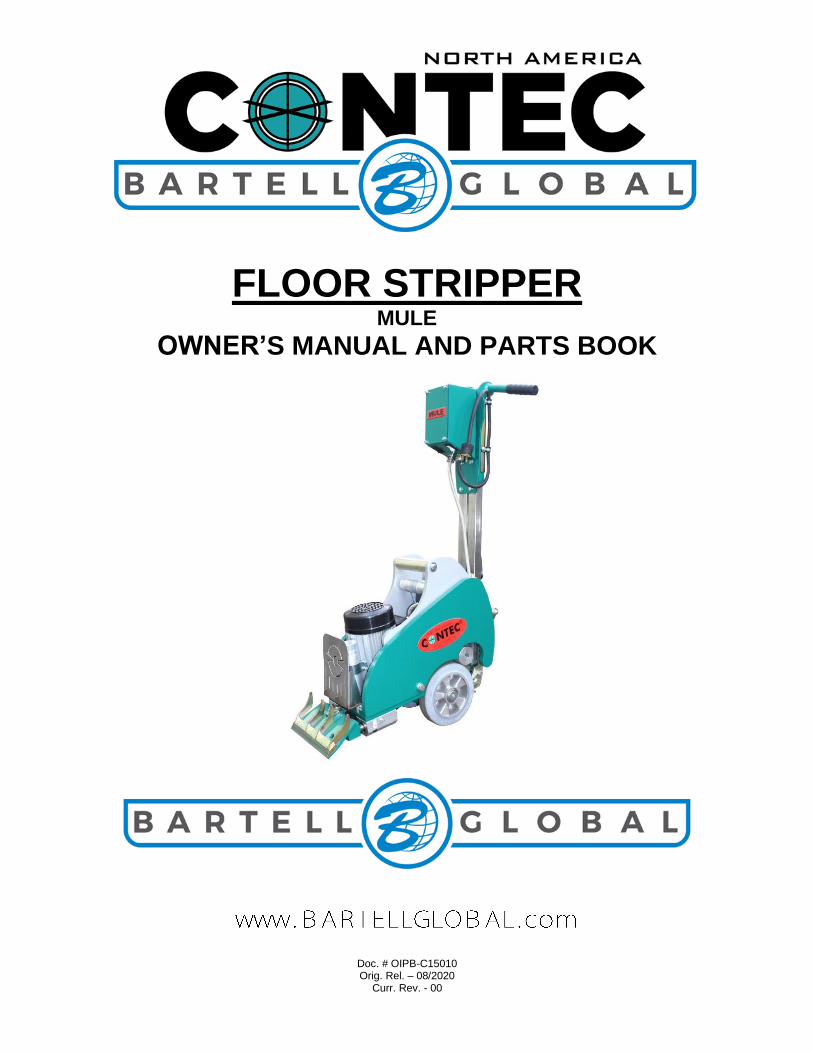
FLOOR STRIPPER MULE
OWNER’S MANUAL AND PARTS BOOK

MULE FLOOR STRIPPER OWNER’S MANUAL
1
OIPB – C15010
Bartell Morrison Inc.
170 Traders Blvd Mississauga, Ontario, Canada
L4Z 1W7 Tel: (647) 953-4100 Fax: (647) 953-4101
Bartell Morrison USA LLC 200 Commerce Drive, Unit A
Freehold, NJ, USA 07728
Tel: (848) 225-8100 Fax: (848) 225-8101
SPE International Ltd Honeyholes Lane
Dunholme, Lincoln, England LN2 3SU
Tel: 01673 860709 Fax: 01673 861119
Innovatech 4701 Allmond Ave
Louisville, Kentucky, USA 40209
Tel: (425) 405-9100 Fax: (425) 405-9101
ORIGINAL LANGUAGE OPERATING MANUAL FOR CONTEC FLOOR STRIPPER
© 2020 Bartell Morrison Inc.
No part of this work may be reproduced or transmitted in any form or by any means, electronic or mechanical, including photocopying and recording, or by any information storage or retrieval
system without the prior written permission of Bartell Morrison Inc. unless such copying is permitted by federal copyright laws.
Address inquiries or reference permissions care of:
Bartell Morrison Inc., 170 Traders Blvd., Mississauga, Ontario, Canada, L4Z 1W7
REV. DATE DESCRIPTION APPROVED BY:
00 08/2020 Updated Format Initial Release AN

MULE FLOOR STRIPPER OWNER’S MANUAL
2
OIPB – C15010
SAFETY PRECAUTIONS
DANGER EXPLOSION HAZARD
Never operate the machine in an explosive atmosphere, near combustible materials, or
where ventilation does not clear exhaust fumes.
CAUTION ROTATING HAZARD
Never place hands or feet inside safety guard rings. Serious injury will result from contact with
rotating tooling.
CAUTION MOVING PARTS
Before starting the machine, ensure that all guards and safety devices are in place and
functioning properly.
ATTENTION READ OWNER’S MANUAL
Read and understand owner’s manual before using this machine. Failure to follow operating
instructions could result in serious injury or death.

MULE FLOOR STRIPPER OWNER’S MANUAL
3
OIPB – C15010
TABLE OF CONTENTS
QUALITY ASSURANCE/ MACHINE BREAK IN 4
WARRANTY INFORMATION 4
SPECIFICATIONS 5
PREVENTATIVE MAINTENANCE AND ROUTINE SERVICE PLAN 6
ROUTINE SERVICE SCHEDULE 7 ROUTINE SERVICE INTERVALS 7
OPERATING SAFETY PRECAUTIONS 8
OPERATION INSTRUCTIONS 9
SETTING UP YOUR MULE FLOOR STRIPPER 9 PRIOR TO OPERATION 9 CHANGING OR INSTALLING TOOLING 9 ADJUSTING THE WEIGHTS 10 OPERATION 11
PARTS LIST – MULE MAIN ASSEMBLY 12
MULE MAIN ASSEMBLY – PARTS LIST 13
DECLARATION OF CONFORMITY 16
MULE FLOOR STRIPPER OWNER’S MANUAL
4
OIPB – C15010
QUALITY ASSURANCE/ MACHINE BREAK IN
The Contec Floor Stripper is the product of extensive engineering development designed to give long life and unmatched performance. The Floor Strippers are shipped completely assembled.
You can help ensure that your Floor Stripper will perform at top levels by observing a simple routing on first use. Consider that your new Floor Stripper is like a new car. Just as you would break in a new car to the road or any new machine to the job, you should start gradually and build up to full use. Learn what your machine can do and how it will respond. Full throttle and control may be used after this time period, as allowed by material. This will serve to further break in the machine on your specific application, as well as provide you with additional practice using the machine.
We thank you for the confidence you have placed in us by purchasing a Contec Floor Stripper and wish you many years of satisfied use.
WARRANTY INFORMATION Bartell agrees to furnish without charge, F.O.B. our plant, a replacement for any part or
portion thereof, comprising the main unit of the Contec Floor Stripper, consisting of the handle, housing assembly, save and except tooling, and power units, prove upon our examination, to be defective in either material or workmanship within a period of twelve (12) months from date of purchase, provided that notice of such defective part or portion thereof is given to Bartell Ltd. within the twelve month warranty period. No further or other guarantee or warranty expressed or implied in connection with the sale of the Floor Stripper is given and our sole liability consists in replacing defective parts or portions thereof. We shall not be responsible for any special, indirect, or consequential damages arising in any manner whatsoever.
This guarantee is for the sole benefit of the original purchaser as end user. Our responsibility under this guarantee ends in the case the original purchaser transfers ownership of the Floor Stripper, makes any changes, or adds any parts or devices not of our manufacture to the Floor Stripper machine.
MULE FLOOR STRIPPER OWNER’S MANUAL
5
OIPB – C15010
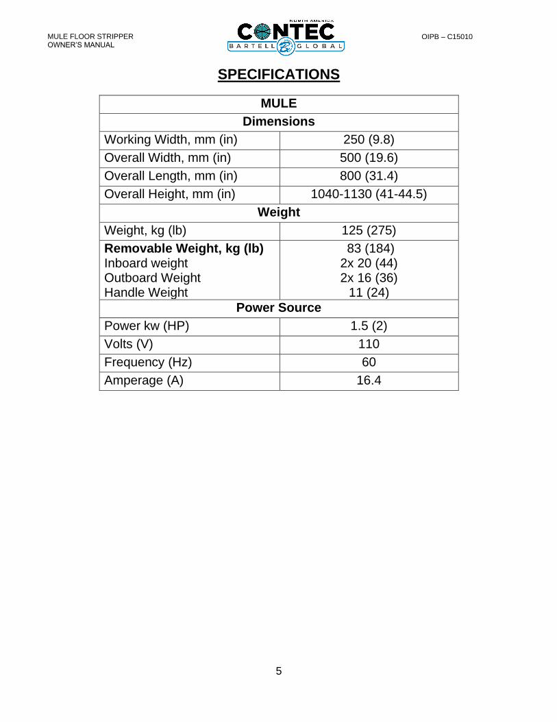
SPECIFICATIONS
MULE
Dimensions
Working Width, mm (in) 250 (9.8)
Overall Width, mm (in) 500 (19.6)
Overall Length, mm (in) 800 (31.4)
Overall Height, mm (in) 1040-1130 (41-44.5)
Weight
Weight, kg (lb) 125 (275)
Removable Weight, kg (lb) Inboard weight Outboard Weight Handle Weight
83 (184) 2x 20 (44) 2x 16 (36)
11 (24)
Power Source
Power kw (HP) 1.5 (2)
Volts (V) 110
Frequency (Hz) 60
Amperage (A) 16.4

MULE FLOOR STRIPPER OWNER’S MANUAL
6
OIPB – C15010
PREVENTATIVE MAINTENANCE AND ROUTINE SERVICE PLAN
This Contec Floor Stripper has been assembled with care and will provide years of service. Preventative maintenance and routine service are essential to the long life of your Floor Stripper. Your dealer is interested in your new machine and has the desire to help you get the most value from it. After reading through this manual thoroughly, you will find that you can do some of the regular maintenance yourself. However, when in need of parts or major service be sure to see your Bartell dealer. For your convenience, we have provided this space to record relevant data about your Floor Stripper. When in need of parts or service be prepared to provide your Floor Stripper serial number. Locate the serial number now and record in the space below. Date Purchased: Type of Machine:
Dealer Name: Model:
Dealer Phone: Serial Number:
Replacement Parts Used Maintenance Log:
Part No. Quantity Cost Date Date Operation
MULE FLOOR STRIPPER OWNER’S MANUAL
7
OIPB – C15010
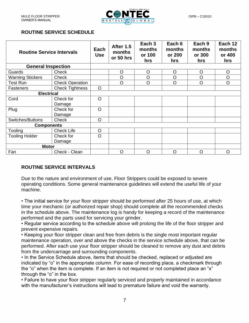
ROUTINE SERVICE SCHEDULE
Routine Service Intervals Each Use
After 1.5 months
or 50 hrs
Each 3 months or 100
hrs
Each 6 months or 200
hrs
Each 9 months or 300
hrs
Each 12 months or 400
hrs
General Inspection Guards Check O O O O O
Warning Stickers Check O O O O O
Test Run Check Operation O O O O O
Fasteners Check Tightness O
Electrical
Cord Check for Damage
O
Plug Check for Damage
O
Switches/Buttons Check O
Components
Tooling Check Life O
Tooling Holder Check for Damage
O
Motor
Fan Check - Clean O O O O O
ROUTINE SERVICE INTERVALS Due to the nature and environment of use, Floor Strippers could be exposed to severe operating conditions. Some general maintenance guidelines will extend the useful life of your machine. • The initial service for your floor stripper should be performed after 25 hours of use, at which time your mechanic (or authorized repair shop) should complete all the recommended checks in the schedule above. The maintenance log is handy for keeping a record of the maintenance performed and the parts used for servicing your grinder. • Regular service according to the schedule above will prolong the life of the floor stripper and prevent expensive repairs. • Keeping your floor stripper clean and free from debris is the single most important regular maintenance operation, over and above the checks in the service schedule above, that can be performed. After each use your floor stripper should be cleaned to remove any dust and debris from the undercarriage and surrounding components. • In the Service Schedule above, items that should be checked, replaced or adjusted are indicated by “o” in the appropriate column. For ease of recording place, a checkmark through the “o” when the item is complete. If an item is not required or not completed place an “x” through the “o” in the box. • Failure to have your floor stripper regularly serviced and properly maintained in accordance with the manufacturer’s instructions will lead to premature failure and void the warranty.
MULE FLOOR STRIPPER OWNER’S MANUAL
8
OIPB – C15010
OPERATING SAFETY PRECAUTIONS The floor strippers are constructed according to existing safety rules and regulations.
These technical precautions should not be removed or changed under any circumstances. While operating the machines the following points should also be kept in mind:
The instructions provided in this manual are done so to ensure the operator’s safety as well as that of others, the equipment, and the job site. Failure to follow these guidelines can lead to serious personal injury and even death. The operator and any service personnel should read and understand the entire manual before working with or servicing any Contec Floor Stripper.
• The floor stripper should always be operated with all safety covers and technical precautions.
• During transport, cleaning, repair or maintenance the floor stripper must be disconnected from the power supply. This also applies to the changing of tools.
• Always remove the tool before transporting the machine.
• Only use tools delivered by CONTEC®.
• The operator should never leave the machine unattended during operation.
• Before leaving the machine, all rotary parts should be brought to a standstill. The floor stripper must be disconnected from the power supply. Make sure that the machine cannot roll or move by itself.
• The Floor Stripper should be switched off immediately if unusual noises or vibrations are detected during the operating of the machinery. A thorough check must be carried out in order to detect the cause.
• After any maintenance and adjustment all safety covers must be reattached.
• Ear protectors must be worn.
• Eye protectors must be worn.
• Safety shoes with steel caps must be worn.
• In the event of a large amount of dust during operation, connect a dust collector to the grinder.
• Depending on the type of floor (floor coating) stripping can produce gases/dust. The operator must be held responsible if these generated gases/dusts are dangerous and if protection is necessary. Stripping floors containing asbestos is especially dangerous and can cause health problems. Special masks must be worn which keep the breathing air clean. A dust collector must be used and should be equipped with filters suitable for asbestos dust.
The floor must be swept before stripping. Anchor screws and bolts coming out of the floor can be better seen if the floor is clean. If the stripping tool strikes an anchor screw or bolt, then serious damage can be caused to the machine or grinding head.

MULE FLOOR STRIPPER OWNER’S MANUAL
9
OIPB – C15010
OPERATION INSTRUCTIONS
SETTING UP YOUR MULE FLOOR STRIPPER Your MULE Floor Stripper comes fully assembled with handle and motor fully installed. The handle is in the lowest position to allow for easier transportation. The handle can be adjusted to suit the operator by loosening the 2 screws at the base of the handle and retightening to set position. Tooling can now be installed, and your Floor stripper is ready for use.
PRIOR TO OPERATION
• Make sure that all dust, debris etc., are thoroughly removed from the unit prior to operation. Special effort should be given to the bottom of the machine where the tooling is located, as well as the drive wheels and motor.
• Check all bolts and screws for tightness and make sure all bolts and screws are securely tightened. Loose bolts and screws may cause damage to the unit. Make sure tooling is properly installed.
CHANGING OR INSTALLING TOOLING
• Lock the centre weights into position 1 (See below “Adjusting the Weights”)
• Tip the machine until it rests in a stable position
• Clean and loosen the bolts of the blade mounting
• Replace the blade.
• Make sure that the blade fits exactly into the support. On normal and hard subfloors, the bevel of the blade should show upwards (B). On soft subfloors the bevel should show downwards (A).
Figure 1: Blade orientation
• Tighten the bolts of the blade mounting again
ATTENTION: Before working on the floor stripper bring the motor to a total stand still and disconnect from the power supply.
CAUTION: Tooling is sharp, set wrench in position opposite to blade to avoid injury

MULE FLOOR STRIPPER OWNER’S MANUAL
10
OIPB – C15010
ADJUSTING THE WEIGHTS The two centre weights can be locked in three different positions. The locking bolt is situated on the right-hand side outside the weight. The bolt must be pulled out before changing the position. Pos. 1: the weight is mostly on the rear traction wheels. The wheels will have increased traction and drive is increased. Pos. 2: The weight is in the middle position and creates an option to transport machine with a crane. Pos. 3: The weight is mostly on the tool. The tools will be less likely to jump up and slide on top of the material trying to be removed.
Figure 2: Weight positioning
MULE FLOOR STRIPPER OWNER’S MANUAL
11
OIPB – C15010
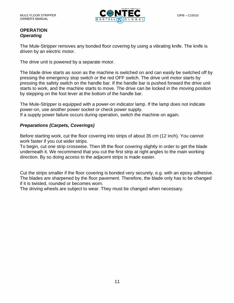
OPERATION Operating The Mule-Stripper removes any bonded floor covering by using a vibrating knife. The knife is driven by an electric motor. The drive unit is powered by a separate motor. The blade drive starts as soon as the machine is switched on and can easily be switched off by pressing the emergency stop switch or the red OFF switch. The drive unit motor starts by pressing the safety switch on the handle bar. If the handle bar is pushed forward the drive unit starts to work, and the machine starts to move. The drive can be locked in the moving position by stepping on the foot lever at the bottom of the handle bar. The Mule-Stripper is equipped with a power-on indicator lamp. If the lamp does not indicate power-on, use another power socket or check power supply. If a supply power failure occurs during operation, switch the machine on again. Preparations (Carpets, Coverings) Before starting work, cut the floor covering into strips of about 35 cm (12 inch). You cannot work faster if you cut wider strips. To begin, cut one strip crosswise. Then lift the floor covering slightly in order to get the blade underneath it. We recommend that you cut the first strip at right angles to the main working direction. By so doing access to the adjacent strips is made easier. Cut the strips smaller if the floor covering is bonded very securely, e.g. with an epoxy adhesive. The blades are sharpened by the floor pavement. Therefore, the blade only has to be changed if it is twisted, rounded or becomes worn. The driving wheels are subject to wear. They must be changed when necessary.

MULE FLOOR STRIPPER OWNER’S MANUAL
12
OIPB – C15010
PARTS LIST – MULE MAIN ASSEMBLY

MULE FLOOR STRIPPER OWNER’S MANUAL
13
OIPB – C15010
MULE MAIN ASSEMBLY – PARTS LIST Item # Part # Description QTY Remarks
1 87612020161 LINEAR BEARING HOUSING 2
2 8755030216 MOTOR 1
3 8727104300 MAIN BEARING HOUSING 1
4 8727104400 FENDER MOTOR 1
5 87612020162 LINEAR-BEARING 4
6 8727103000 MAIN PLATE 1
7 8727101708 BLADE HOLDER ADJUSTABLE 1
8 8727103902 BLADE BRACKET ADJUSTABLE 1
9 8727103903 BRACKET FOR BLADE ADJUSTABLE 1
11 8727101609 ROD AXIS 1
13 8727104102 ROD BEARING WASHER 1
15 8727104301 ECCENTRIC DRIVE SHAFT 1
16 876160082ZC3 BEARING 2
17 876160102ZC3 BEARING 1
18 8761210130 GREASE NIPPLE 2
19 8727101604 CONNECTING ROD 1
20 8784833080 SLIDE BUSHING 20MM 2
21 8727104200 WHEEL AXIS 1
22 8784832315 SLIDE BUSHING 15MM 2
23 8780203200 REAR WHEEL 2
24 87612020163 SEALING 4
30 8770261800 BRACKET FOR RUBBER BLOCK 2
31 8727100603 SQUARE BRACKET 2
32 8770261850 RUBBER BLOCK 2
33 8727100600 MOTOR MOUNTING PLATE 1
35 8750202041G GEARBOX 1
37 8750212341 DRIVE UNIT MOTOR 1
38 8750212241 CAPACITOR 1
39 8727101606 WHEEL ON DRIVE MOTOR 2
41 8727100700 HANDLE BRACKET 1
42 87GN6049510I CLAMPING LEVER 2
43 8727103500 HANDLE 1
44 8730100304 DRIVE UNIT LEVER ALLOY 1
45 8750201002 DRIVE UNIT SWITCH HEAD 1
46 8750201001 DRIVE UNIT SWITCH COMPLETE 1
47 8727103600 HANDLE COVER 1
48 8770212610 RUBBER GRIP 2
49 8750201056 SWITCH 1
50 8727100900 BRACKET FOR DRIVE ADJUSTMENT 1
51 8727100900 SPACER DRIVE ADJUSTMENT 2
53 8727100802 BEARING 1
55 8761206002 DRIVE ADJUSTMENT LEVER 2

MULE FLOOR STRIPPER OWNER’S MANUAL
14
OIPB – C15010
57 8727100800 DRIVE ADJUSTMENT LAVER 1
67 8727103204 CONNECTION BRACKET 1
69 87212313 PLUG HOUSING 1
71 87502020131 PLUG PIN MOUNTING 1
73 87502020121 JACK IN THE HOUSING 1
75 8750202013 SOCKET HOUSING 1
81 8727101111 ROD PIN BRACKET 1
85 8727104302 SPACER BEARING HOUSING 1
89 8761411050 TENSION SPRING 1
91 8705421812 HOSE CLAMP 1
101 8727103200 WEIGHT OUTSIDE LEFT 1
102 8727103205 WEIGHT OUTSIDE RIGHT 1
103 8727103300 INNER WEIGHT LEFT 1
104 8727103305 INNER WEIGHT RIGHT 1
105 8727103400 WEIGHT CONNECTOR 1
107 8727104000 SCRAPER 2
108 8727103701 DISTANCE RING REAR WHEEL 2
111 8790200069 SNAP PIN 3
113 87GN1112014B CHAIN FOR PIN 1
131 8750212241 CAPACITOR 1
137 8790200024 STRAIN RELIEF 1
MULE FLOOR STRIPPER OWNER’S MANUAL
15
OIPB – C15010
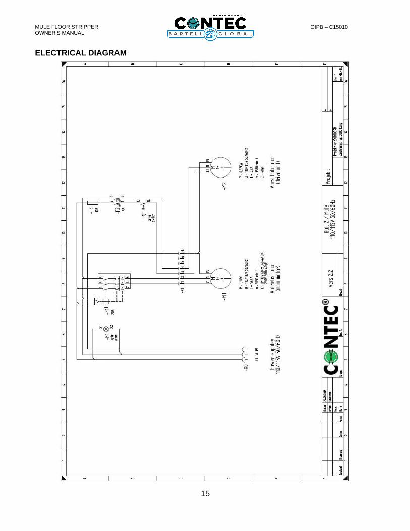
ELECTRICAL DIAGRAM
MULE FLOOR STRIPPER OWNER’S MANUAL
16
OIPB – C15010
DECLARATION OF CONFORMITY Declaration of Conformity / Certificat de conformité / Gelijkvormigheids certificaat Declaración de
Conformidad/Declaração de Conformidade/Dichiarazione Di Conformita
We: Bartell Morrison Inc. Bartell Morrison (USA) LLC.
375 Annagem Blvd. 200 Commerce Drive, Unit A Mississauga, Ontario, Canada Freehold, New Jersey, United States of America L5T 3A7 07735 Tel: 647-953-4100 Tel: 848-225-8100 Fax: 647-953-4101 Fax: 848-225-8101
Declare under our sole responsibility that the product to which this declaration relates is in conformity with the following standard(s) or other normative documents. Déclarons sous notre responsabilité que le produit cette déclaration est conforme aux normes suivantes ou d’autres documents habituels. Verklaren onder onze verantwoordelijkheid dat het product naar welke de verklaring verwijst conform de volgende standaards of anders gebruikelijke documenten is. Declaramos bajo nuestra única responsabilidad que el producto en lo que esta declaración concierne, es conforme con la siguiente normativa u otros documentos. Declara sob sua responsabilidade que o produto a quem esta declaração interessar, está em comformidade com os seguintes documentos legais ou normas directivas. Dichiariamo sotto la ns. unica responsibilita che il prodotto al quale questa dichiarazione si riferisce, è fabbricato in conformità ai seguenti standard e documenti di normative. EN 349:1993 Safety of Machinery - Minimum gaps to avoid crushing of parts of the human
body. EN 418:1993 Safety of Machinery - Emergency stop equipment, functional aspects - Principles
for design EN 12100-1:2003 Safety of Machinery - Basic Concepts, general principles for design - Part 1: Basic
Terminology, methodology EN 12100-2:2003 Safety of Machinery - Basic Concepts, general principles for design - Part 2:
Technical Principles EN ISO 4872:1978 Acoustics - Measurement of Airborne noise emitted by construction equipment
intended for outdoor use - Method for determining compliance with noise limits. EN ISO 5349-1:2001 Mechanical vibration. Measurement and evaluation of human exposure to hand-
transmitted vibration. General requirements EN ISO 5349-2:2001 Mechanical vibration. Measurement and assessment of human exposure to hand-
transmitted vibration. Practical guidance for measurement at the workplace. Following the provisions of Directive(s): Suivant les directive(s) déterminées: Volgens de vastgestelde richtlijnen: Siguiendo las directiva(s): No sequimento das clausulas da Directiva(s): Seguendo quanto indicato dalla Direttiva(s): 98/37/EC Machinery Directive 2000/14/EC Noise Directive 2001/95/EC General Product Safety Directive 2002/95/EC Reduction of Hazardous Waste Directive