Embed Size (px)
Citation preview

Muddy Consultants Presents: Big Muddy Trail Area Restoration
TL- Alex Watson Graham Burkholder Danny Shannon
Clark Hartmann Jeremy Metz Mike Grassi
University of Missouri - College of Engineering
E3508 Lafferre Hall
Columbia, MO, 65203
Cell: 816-805-6251 Email: [email protected]

Executive Summary
Arrow Rock is a small town about 40 minutes West of Columbia. The Big Muddy Fish and
Wildlife Refuge is just East of the town and is in need of restoration. The main problems are as
follows: flooding makes the trail inaccessible several times a year, the decaying bridge, the
erosion of the old levee, erosion of the trail, and limited parking space for visitors.
After an initial site investigation Muddy Consultants were able to discover more about the trail
area. The existing wooden pedestrian bridge is decaying as a result of high humidity and frequent
flooding. During the site visit Muddy Consultants found that a spring water stream feeds into the
stream and directly into the side of the levee. The spring enters just downstream of the bridge.
This causes turbulence which has eroded much of the old levee. In order to proceed, the stream
needs to be redirected and/or the levee needs to be armored with riprap. The trail that leads up to
the bridge is also in danger of erosion as a smaller stream runs along side. Lastly, Muddy
Consultants found that the site sub surface is almost entirely made up of soft clays and silts. This
soil has a strength of between 250 and 300 psf.
Muddy Consultants was tasked with addressing the issues stated above and doing so under
certain requirements. The trail needs to be accessible during flood events so that visitors can
enjoy the trail at all times. The existing bridge is decaying and is overtopped frequently. It needs
to be replaced with a bridge that will span from the height of the top of the levee. Any
construction must be done with little to no use of large vehicles since the trail is not very heavy
vehicle accessible. New construction needs to have minimal impact on the environment. Future
maintenance needs to be minimal. Finally, Muddy Consultants was given a tentative budget of
$250,000.
Initially, Muddy Consultants believed a truss bridge made of weathering steel, with connecting
catwalk would be the best solution to the main issue. While it would keep the path above flood
waters, this solution is most likely not an option. This is because the bridge will weigh too much
to lift by helicopter. Due to that major issue Muddy Consultants now suggests a bridge made of
two weathering steel I-beams. This type of bridge will cost much less and will be much easier to
construct. Muddy Consultants also suggest armoring the bank opposite the spring water stream
to prevent further erosion of the levee. Step pools are suggested to slow down the flow under the
bridge to further prevent erosion. Muddy Consultants has completed drawings and cost analysis
for the suggested items.

Introduction and Current Situation
Muddy Consultants intends to replace a bridge and improve trail accessibility for the Big Muddy
Fish and Wildlife Refuge. The current bridge cannot always serve its purpose as it is often
underwater during flood events. This bridge deck is made of wood, which is currently rotting.
Tim Haller, the Visitor Services Manager for Big Muddy, has proposed that Muddy Consultants
should come up with a plan to replace this bridge as well as fix some other issues in the area
(Figure 1). As a team, we have decided what we are going to recommend and how to improve
the area.
Figure 1: Bridge and Stream Erosion Looking Upstream
The first key issues are deciding the location for the new bridge as well as what type of bridge to
use. The old wooden bridge is in poor condition as a result of flooding in the area. High
humidity and low sunlight has caused the current bridge to rot (Figure 2). The new bridge will
need to be placed higher up on the levee so it is above flood waters. This is the main issue, but
there are several others that need to be dealt with. The next issue is a spring water stream that
intersects with the bridge stream just downstream of the bridge.
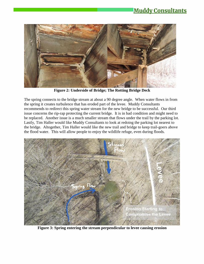
Figure 2: Underside of Bridge; The Rotting Bridge Deck
The spring connects to the bridge stream at about a 90 degree angle. When water flows in from
the spring it creates turbulence that has eroded part of the levee. Muddy Consultants
recommends to redirect this spring water stream for the new bridge to be successful. Our third
issue concerns the rip-rap protecting the current bridge. It is in bad condition and might need to
be replaced. Another issue is a much smaller stream that flows under the trail by the parking lot.
Lastly, Tim Haller would like Muddy Consultants to look at redoing the parking lot nearest to
the bridge. Altogether, Tim Haller would like the new trail and bridge to keep trail-goers above
the flood water. This will allow people to enjoy the wildlife refuge, even during floods.
Figure 3: Spring entering the stream perpendicular to levee causing erosion
to

Objectives and Requirements
Muddy Consultants plans to address several issues in the Big Muddy Fish and Wildlife Refuge
including existing bridge replacement, trail accessibility, flooding control measures, and some
other issues brought up by Tim Haller or noticed by our firm. Our firm recommends replacing
the current bridge with a steel alternative or suspension alternative. Either way, the current
bridge is becoming unstable and rotted, leading to a possibility of danger for future bridge users.
The current trail floods several times a year and our solution is a possible elevated walkway over
the existing trail. This will allow visitors to visit the wildlife refuge while flooding is occurring.
Our new bridge will be at the height of the levee allowing the bridge greater longevity by
reducing exposure to water. Levee cutting is a current issue that needs to be immediately
addressed. We propose a large amount of rip rap in the levee cutting area to reduce erosion and
stabilize the stream bank. The small stream area near the trailhead was looked at and flooding
mitigation will be considered although this area is not going to be our main focus. The current
streambank stabilization methods have almost completely washed away (Figure 4) and are in
need of repair and replacement. Lastly, Muddy Consultants will come up with new strategic
locations to place riprap and geotextile in order to limit erosion in the bridge area. Lastly, our
firm suggests an updated parking options so that visitors may have easier access to the trail and
to promote the trail itself.
Figure 4: Rip rap removed due to high water velocities

Environmental Impact
Muddy Consultants plan to implement a responsible and sustainable environmental strategy to be
used in order to ensure minimal disturbances during the construction of the bridge and trail. Our
design team made an emphasis to lie lightly on the land when considering bridge options and
walkway alternatives. Our firm will also recommend a tree replacement or native vegetated areas
program to improve the trees which may be removed during the construction phase. During the
construction phase Muddy Consultants recommends that proper environmental protections
practices are used such as silt fences and swales where necessary. Overall, we do not see any
major environmental impacts for this project but will continue accessing any risks throughout the
entire design process.
Hydrology
Muddy consultants have computed hydrology information regarding the bridge site in order to
get a gauge of necessary flooding and erosion protections. Using data from NOAA and the
NRCS manual, our team has computed peak flows and velocity for the roughly 1.67mi2
watershed designated by our team below.
Figure 5: Watershed for Flows Passing Through Bridge Site
Using Manning's Equation for flow velocity as well as 7.61in of expected rainfall in this area,
our team has calculated that in a 100-year storm event, flows from the creek and peak at up to 11
ft/s. This seems like an extremely high flow but it is important to keep in mind this number is
only for a worst case scenario expected about every 100 years. Any bridge abutments or columns
will be designed to withstand flows at this magnitude. Next, we computed the flows that could
possibly be passing through the site during a 100-year storm event, another worst case scenario.
Flows have been calculated to be up to 767 cfs in a storm event specifically from the watershed
shown. Additional flows from the Missouri River and further upstream can contribute during
these storm events. Our recommendations are to install hydraulic structures upstream from the
bridge to slow high velocity flows in order to reduce cutting and erosion. An example of a
possible hydraulic structure could be rip-rap step pools. Rip Rap is also recommended to be used
along the levee downstream from the bridge in order to reduce cutting which has become a
serious problem recently. Cost analysis for rip-rap can be found in the cost analysis section of
this report. Additional hydraulic information can be found at the appendix of this report.
Truss Bridge Options
The replacement bridge would be a steel truss bridge made of prefabricated 100 ft spans. The
cost of each of these spans is approximately $118,900 per span before construction. This range is
so large because there is so much variability in the bridge properties such as material, shape, and
other factors specific to the project. This bridge will be designed economically, so a cost closer
to the low end of that range can be expected.
Since this is a pedestrian bridge, the only loads being designed for are pedestrian loads, which,
according to AASHTO, means accommodating a 10,000 lb H5 truck, as well as a uniform
pedestrian load of 90 psf (AASHTO 2009). The spans would be 8 ft wide to allow for
comfortable use. The deck on this bridge would be made of wood or recycled plastic planks. The
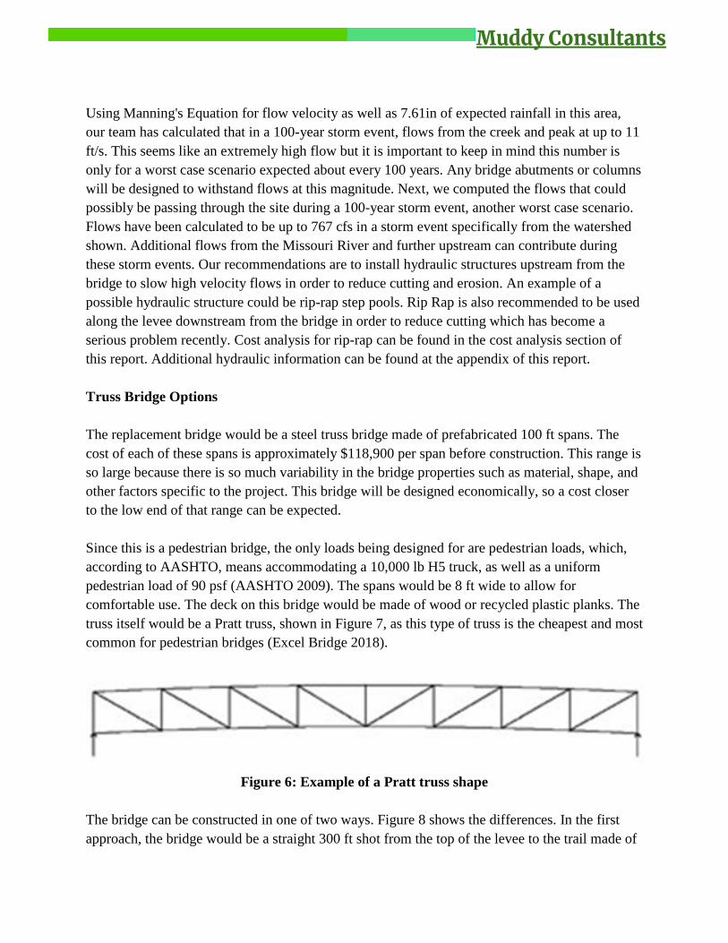
truss itself would be a Pratt truss, shown in Figure 7, as this type of truss is the cheapest and most
common for pedestrian bridges (Excel Bridge 2018).
Figure 6: Example of a Pratt truss shape
The bridge can be constructed in one of two ways. Figure 8 shows the differences. In the first
approach, the bridge would be a straight 300 ft shot from the top of the levee to the trail made of
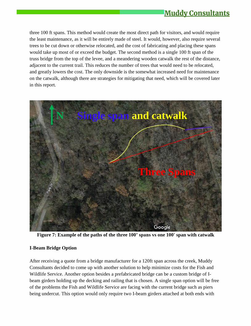
three 100 ft spans. This method would create the most direct path for visitors, and would require
the least maintenance, as it will be entirely made of steel. It would, however, also require several
trees to be cut down or otherwise relocated, and the cost of fabricating and placing these spans
would take up most of or exceed the budget. The second method is a single 100 ft span of the
truss bridge from the top of the levee, and a meandering wooden catwalk the rest of the distance,
adjacent to the current trail. This reduces the number of trees that would need to be relocated,
and greatly lowers the cost. The only downside is the somewhat increased need for maintenance
on the catwalk, although there are strategies for mitigating that need, which will be covered later
in this report.
Figure 7: Example of the paths of the three 100’ spans vs one 100' span with catwalk
I-Beam Bridge Option
After receiving a quote from a bridge manufacturer for a 120ft span across the creek, Muddy
Consultants decided to come up with another solution to help minimize costs for the Fish and
Wildlife Service. Another option besides a prefabricated bridge can be a custom bridge of I-
beam girders holding up the decking and railing that is chosen. A single span option will be free
of the problems the Fish and Wildlife Service are facing with the current bridge such as piers
being undercut. This option would only require two I-beam girders attached at both ends with
Three Spans
N Single span and catwalk

concrete piling. However, Muddy Consultants also recommends constructing a MSE wall at the
levee side to reduce girder span lengths. This MSE wall will need to be protected by rip-rap for
high velocity flow scenarios. It may be possible to connect the I-beam girders directly to the
MSE wall eliminating the need for a concrete pile on the levee side. In all, the I-beam bridge
will save Big Muddy more than $50,000 compared to the steel truss bridge.
Figure 8: Proposed I-Beam Bridge Crossover with Abutments
Spanning the entire creek, the I-beams could start to get costly after 25ft as this is the maximum
length most manufactures will carry without a custom order being made. As far as
constructability goes, typical weights for these types of I-beams are 31.8lb/ft.
Steel Options
If a steel truss bridge is used to replace the current wooden bridge, the type of steel will be an
important aspect. There are three options for this project: painted steel, galvanized steel, and
weathering steel. Each type of steel has its own benefits and drawbacks.
Painted steel can be very aesthetically pleasing, but it has a few drawbacks. The biggest issue is
that it requires occasional touchups and may need to be completely repainted every 15 years.
This of course depends on the quality of paint used. One of the most important criteria for the
client is to decrease maintenance. If these touchups are not performed, the steel will oxidize
more rapidly and thus decrease the service life of the bridge. This makes painted steel less
desirable. On top of that painted steel is actually more expensive than weathering steel.
However, it is still far less expensive than galvanized steel.

Weathering steel is the second option for the proposed bridge. This type of steel is also
aesthetically pleasing considering the proposed location. The outer layer of the weathering steel
oxidizes over 3 – 12 months. This outer layer slows oxidation for the rest of the steel and can
allow the bridge to last up to 120 years (Corus Construction and Industrial 2005). Since the steel
naturally forms a protective layer it requires very little maintenance. Weathering steel is also the
cheapest option between the three types of steel. It is 5% cheaper than painted steel (Corus
Construction and Industrial 2005). The biggest issue with weathering steel is that it does not do
well in excessively humid environments; however, excessively humid refers to climates of
continuous humidity. A cycle of wet and dry is beneficial to weathering steel’s controlled
corrosion process. The trees drop their leaves in the fall which greatly reduces the humidity in
the area during the colder months. Therefore, this site will not have any problems with excessive
corrosion.
Galvanized steel is the third and final option for the bridge spans. The biggest hit against
galvanized steel is its cost. It is far more expensive than the other two types because the steel is
dipped in molten zinc. The zinc coating protects the steel from oxidizing. As far as oxidation
mitigation goes, galvanized steel is better than the other two. Another issue with galvanized
steel is the aesthetics. A large, shiny, silver bridge may look out of place in the middle of a
wildlife refuge.
Muddy Consultants suggest using weathering steel for the proposed bridge. It is the most
economic option, and perhaps the most aesthetically pleasing for the given environment. The
fact that weathering steel requires little maintenance over its design life is also an important
factor in this choice. Weathering steel does not perform well in “excessive humidity.” However,
Big Muddy does not fit this description since it is not continuously humid through the seasons.
This means weathering steel will not oxidize too quickly and is therefore the best candidate for
the proposed bridge.
Type of Steel
Criteria Weathering Painted Galvanized
Initial Cost
Maintenance
Corrosion
Resistance
Aesthetics
Table 1: Benefits and Drawbacks for Each Type of Steel
Bridge Placement Options
Originally, Muddy Consultants planned to have the prefabricated bridge delivered to the site and
then use a helicopter to get it in place. This seemed the best option because it is close to, if not,

impossible for large machinery to access the site. Unfortunately, the bridge will be too heavy for
a helicopter to lift. CONTECH estimated that the heaviest crane pick for the proposed 120ft
bridge would weigh 45,400lbs. The United States Military’s largest helicopter is the Sikorsky
CH-53E Super Stallion. It can only carry 14.5 tons externally (Helipress 2017) which means the
helicopter could not lift the bridge. The only other option is using cranes to lift the bridge into
place. Big Muddy is not the ideal place for cranes since there are many trees and the soil is very
soft. There are cranes that can lift the proposed bridge, but they are too big to access the bridge
site. That is true unless a lot of trees are cut down. For these reasons Muddy Consultants now
recommends the I-beam system discussed earlier, instead of a steel truss bridge.
Proposed Bridge Abutment
Muddy Consultants proposes that Mechanically Stabilized Earth (MSE) Walls be constructed at
each end of the bridge to serve as abutments. MSE walls were selected due to their relatively low
cost, ease of construction, and lack of maintenance required throughout the design life. MSE
walls are common for single span bridges (Bourdeau & Zevgolis 2007), and their reduced
“bump” at the ends of the bridges is ideal for bike and ATV traffic. Additionally, MSE Walls are
less susceptible to differential settlement compared to other abutment options (Bourdeau &
Zevgolis 2007). Muddy Consultants recommends that new fill is brought to the site and is used
as the backfill for the MSE walls due to the low strength of the clay currently at the site.
Proposed Catwalk
Muddy Consultants proposes that an elevated catwalk be built next to the existing trail to allow
access to the area during flooding (Figure 9). The catwalk is to be built next to the existing trail
to allow for use of the trail during construction of the catwalk. The catwalk should comply with
current ADA standards upon completion of construction to allow everyone to enjoy the trail.
Muddy Consultants proposes that the catwalk deck is to be made from either pressure treated
plywood or HDPE (High Density Polyethylene) plastic lumber. The main advantage of plywood
over plastic is that its initial cost is two to three times less than that of recycled plastic.
Additionally, it is more commonplace, therefore making it easier to acquire the materials with
the desired strength and appearance. Even though recycled plastic is more expensive up front, the
client is likely to save more money later on because recycled plastic does not deteriorate like the
wood and requires less maintenance. Most wood decks have a 15 year life span (123 Remodeling
2015), but when exposed to excessive moisture without proper maintenance, the lifespan can be
even less. HDPE plastic lumber has a 50 year lifespan, and most manufacturers even provide a
50 year warranty on their product (123 Remodeling 2015). Additionally, by selecting recycled
plastic as a building material, the client is re-using a product that would otherwise end up in a
landfill.

Figure 9: Plan View of Proposed Catwalk
Geotechnical Investigation
Since no existing soil information was provided for the site, Muddy Consultants performed field
tests on the soil. A split spoon sampler was driven into the ground (Figure 10) and pocket
penetrometer tests were performed on the soil sample at two different depths. The pocket
penetrometer gave unconfined compressive strength readings of 0.9 tsf at the surface and 1.5 tsf
6ft below the ground surface. These readings correlate to undrained shear strength (Su) values of
450 psf and 750 psf respectively. Based on these readings, the soils were defined as soft clay and
medium clay respectively (Coduto 1999). Our team does not anticipate that rock will be
encountered within the top 20 ft of soil being considered in our design. The groundwater table
depth was assumed to be at the surface due to flooding at the site. Based on these assumptions
and the soil sample obtained from the field, a preliminary soil profile was created (Figure 11).

Figure 10: Soil sample from Big Muddy Trail site
Figure 11: Preliminary soil profile for the Big Muddy Trail site
Penetrometer
Split Spoon
Sampler

Proposed Catwalk Foundation
For the catwalk foundation, our team proposed that drilled piles be used due to the softness of the
clay on site and the lack of heavy machinery required. Our team suggests that the piles be either
timber or concrete. Timber piles have the lower cost and are easier to construct than concrete
piles, however, they are not as durable as concrete piles when subjected to cycles of wetting and
drying. Therefore, Muddy Consultants recommends using concrete piles if the extra money is
available. Pile lengths, diameters, and spacing were designed to hold an H5 truck and 90 psf
pedestrian live load according to AASHTO’s Pedestrian Bridge Standards. Muddy Consultants
recommends placing pair of 1.5 ft diameter piles spaced 25 feet apart and drilled 19 ft below the
ground surface. This design was based on the ultimate capacity of the piles with a factor of safety
of 3.0. Figure 12 shows a graph of skin friction, base resistance, and ultimate load capacity of the
piles vs depth. Skin friction and base resistance values were found based on the pocket
penetrometer readings from the site investigation. The ultimate load capacity of the piles is the
sum of the skin friction and base resistance. Additionally, this design was chosen because it will
require the least volume of materials compared to other spacing, length and diameter options
(Figure 13), and it will have sufficient uplift capacity (Figure 14). Figure 15 shows a sketch-up
for the timber supports and the concrete supports.
Figure 12: Skin friction, base resistance, and ultimate load vs depth for a 1.5’ diameter pile
0.0
2.0
4.0
6.0
8.0
10.0
12.0
14.0
16.0
18.0
20.0
0 10 20 30 40 50 60
Dep
th (
ft)
Load (k)
Skin Friction (Fs)
Base Resistance (Qb)
Ultimate Load (qult)

Figure 13: Material volume for various pile spacing and depth options
Figure 14: Uplift capacity for various pile spacing and depth options
0.00
10.00
20.00
30.00
40.00
50.00
60.00
70.00
5' Spacing7' Depth
10' Spacing10' Depth
15' Spacing13' Depth
20' Spacing16' Depth
25' Spacing19' Depth
Mat
eria
l Vo
lum
e (y
d^3
)
Pile Spacing and Depth Options
Material Volume
0
5
10
15
20
25
30
35
40
5' Spacing7' Depth
10' Spacing10' Depth
15' Spacing13' Depth
20' Spacing16' Depth
25' Spacing19' Depth
Up
lift
Cap
acit
y (k
)
Pile Spacing and Depth Options
Uplift Capacity (k)

Figure 15: Supports for Catwalk
Connections
To ensure safety of pedestrians and wildlife, as well as for the well-being of the bridge, proper
connections must be made between all parts of the bridge and catwalk. For the catwalk,
connecting the support beams to the piles is the primary concern. Using 1 inch diameter
galvanized A325 steel bolts, the following connection will be provided for the pile. In concrete
piles, the anchor bolts can be embedded or drilled into the pile. The two planks used to make the
supporting beam will be connected to the pile, shown in Figure 16, then connected once more 16
inches apart on each side, with the ends of the beams being 21 inches from the center of each
pile. Another set of bolts will connect the planks 7 inches from the end of the planks, as shown
below (Figure 17) (FEMA 2005).
1.5’ 19’ 19’
Supports spaced 25’ along length of catwalk

Figure 16: Diagram showing how wooden beam connects to piles.
Figure 17: Reference for splicing wooden beams and layout of bolts at connection to pile.
The bolts will go through the support beam and the pile. A notch will be cut into each pile to
ensure proper bearing, as shown in Figure 18. The beam should ideally have no gaps between it
and the pile, and should allow for 4 inches from the top of the pile and beam to the centerline of
the top bolt. The planks on the deck can simply be nailed or screwed into each beam to provide
connection (FEMA 2005).

Figure 18: Standard wooden pile connection cross-section
The truss bridge would have connections that are standard at Contech. These details use three
bearing plates held under each corner with two anchor bolts connected with a washer and two
nuts (Figure 19 and 21) (Contech 2012).
Figure 19: Truss bridge bearing connection to abutment.
The truss members will be held together in a splicing method shown in Figure 20.

Figure 20: Truss member spliced connections
The deck will also be made of planks, and be screwed into the stringers and bottom chords of the
bridge, seen in Figure 21.
Figure 21: Cross section of bearing at abutments and connection details of the deck.
Rip Rap
With the construction of the catwalk and bridge the current stream situation needs to be remedied
regarding the current erosion issues. The main concern would be the side of the levee that is
eroding away due to the spring perpendicular to it. This is shown in Figure 3. Rip rap would be a
good option to mitigate erosion while also being a cost-effective option. Accounting for the 100-
year storm worst-case scenario as mentioned earlier, the recommended size of rip rap required
for the stream would be 10". This was calculated using the equation in Figure 22.

Figure 22: Rip Rap Size Formula
For the levee erosion area, approximately 20 tons of rip rap would be required to properly fill the
area. Per the NRCS design guide on rip rap, the slope for 10"+ diameter rip rap would have to be
32 degrees (NRCS Engineering). This would require that the current levee area that has eroded to
be regraded to the specified slope. The proper depth of rip rap to ensure longevity of the project
would be 18" deep. A full side view of the rip rap can be seen in Figure 23.
Figure 23: To-Scale Side View of Levee Rip Rap
For the stream bed underneath the current bridge, erosion is an issue as well. To counter-act the
erosion the inclusion of a step pool would be recommended to slow down the flow of water
through that area. Figure 24 shows how the step pools would look and work in the proposed
location. The current proposal would be to add rip rap for a 100 ft stretch upstream of where the
bridge is located across the entire width of the current stream. For this project, approximately 90
tons of rip rap would be required to construct the step pools.

Figure 24: Proposed Step Pool Implementation
Cost Analysis
For this project, there is a budget of $250,000. Some of the considerations in the cost analysis
would be considered “optional” in the replacement of the bridge system. Muddy Consultants is
always looking to provide the best design work for each client, which is why extra options are
included within the cost analysis. This way, the client can construct exactly what they want
depending on how much they are willing to spend.
Table 2: Cost Breakdown for Each Project Component
Project Cost ($)
Bridge 65,000
Catwalk 144,000
Rip Rap 4,950
The first cost analysis that needs to be performed would be for the 100 foot bridge itself. The
current suggestion is for a single span bridge to be placed at the same height as the levee. This
would allow the citizens and park visitor to view the flood from above as is highly recommended
by the client. The cost for this bridge can be split up between materials costs. Two W14X22 steel
I beam girders for the bridge would be $4,000 (Midwest Steel and Aluminum). For the decking,
treated lumber at an 8 foot width would cost $1,000 for the 100 foot span (Home Depot). The
MSE walls would cost $10,200 (FDOT Structures Manual). This would bring the total cost for
the bridge up to $15,200 for the materials. With labor included, this would raise the cost to
around $65,000 (Excel Bridge). The catwalk and the bridge would fall under the $250,000
budget. The client could then decide to construct other suggestions such as step pools with the
remaining budget.
A catwalk would be necessary to span the floodplain to reach the new, elevated bridge. Timber
pilings would be the cheaper option, but they would only give a design life of around 17 to 30
years. For the concrete pilings, it would cost $144,000 for the entire length of the catwalk, which
includes the labor cost (Permatrak).

The Muddy Consultants would add rip rap to the levee where it is currently eroding and also
underneath the new bridge. There is a section of the levee near the bridge that has been eroded
by a nearby spring waterway and must be fixed. This procedure is not an optional expenditure as
this is an issue that needs to be fixed before it gets worse and collapses the levee. The rip rap
needed for the levee erosion prevention would cost about $850 (Wireless Estimator) for the rock
to be shipped to the location. Rip rap with 10”+ diameters would be required for this project due
to the amount of water passing through. Step pools under the bridge would be another area to rip
rap since it is experiencing erosion as well. However, this area is not currently a large issue and
the expense for this certain project could be considered non-necessary. It could still be beneficial
to slow the water down in this area though, through the use of step pools. For a 100 foot length
of step pools, it would cost about $4,100 (Wireless Estimator).

References
123 Remodeling. (2015). “5 Decking Materials – costs, benefits and life-span.”
<http://123remodeling.com/decking-materials/> (Apr. 22, 2018).
AASHTO (2009). "LRFD Guide Specifications for the Design of Pedestrian Bridges",
http://www.wsdot.wa.gov/eesc/bridge/designmemos/11-2009.pdf (4/11/18)
Bourdeau, P. & Zevgolis, I (2007). “Mechanically Stabilized Earth Wall Abutments for Bridge
Support”
Coduto, Donald P. (1999). Geotechnical Engineering: Principles and Practices. Upper Saddle
River, NJ: Prentice Hall.
Concrete Network, https://www.concretenetwork.com/concrete-prices.html (4/22/18)
Contech (2012). "Pedestrian Truss Bridge Details",
http://www.conteches.com/DesktopModules/Bring2mind/DMX/Download.aspx?PortalId=0&Ent
ryId=1890 (4/11/18)
Excel Bridge, http://www.excelbridge.com/for-owners/cost (4/22/18)
FEMA (2005). "Wood Pile-to-Beam Connections", https://www.fema.gov/media-library-
data/20130726-1536-20490-3614/fema499_3_3.pdf (4/22/18)
FDOT Structures Manual,
http://www.fdot.gov/structures/structuresmanual/2007january/DesignGuidelines/SDG9.2CostEst
imatingProcess.htm (4/21/18)
Home Depot, https://www.homedepot.com (4/21/18)
NOAA
https://hdsc.nws.noaa.gov/hdsc/pfds/ (4/21/18)
NRCS Manual
https://www.nrcs.usda.gov/wps/portal/nrcs/site/national/home/ (4/21/18)
Midwest Steel and Aluminum,
https://www.midweststeelsupply.com/store/hotrollsteelbeam (4/21/18)

Permatrak, https://www.permatrak.com/news-events/bid/97419/boardwalk-construction-
estimates-how-much-does-a-boardwalk-cost (4/22/18)
NRCS Engineering,
https://www.nrcs.usda.gov/Internet/FSE_DOCUMENTS/nrcs144p2_025594.pdf (4/22/18)
Wireless Estimator, http://wirelessestimator.com/content/industryinfo/702 (4/22/18)
Corus Construction and Industrial. (2005). ‘Weathering Steel Bridges’.
http://resource.npl.co.uk/docs/science_technology/materials/life_management_of_materials/publ
ications/online_guides/pdf/weathering_steel_bridges.pdf (Apr. 20, 2018).
American Galvanizers Association. (2018). ‘Hot-Dip Galvanized Steel vs. Weathering Steel’.
https://galvanizeit.org/uploads/publications/Galvanized_Steel_vs_Weathering_Steel.pdf (Mar.
17, 2018).
Helipress. (2017). ‘The top 5 heavy-lift helicopters in the world’.
http://www.helipress.net/schede-708-the_top_5_heavy_lift_helicopters_video (Apr. 21, 2018).

Appendix
Hydrology Calculations
CN=86
Ia/P=0.04
Ia= 0.326
Avg Slope= 0.2%
r = a/pw
a = 17ft*4ft = 68ft^2
pw = 17ft
r = 4
s = 0.2
n = (Engineeringtoolbox.com) Floodplains Trees = 0.15
V= up to 11ft/s
Unit peak Discharge (graphical method) = 450 csm/in
WQv= P * I
Rv = 0.05 + (0.009*15%)
Rv= 0.185
P = 7.61in
WQv= 1.4
Qp = qu*A*WQv
Qp = 767 cfs Over entire watershed
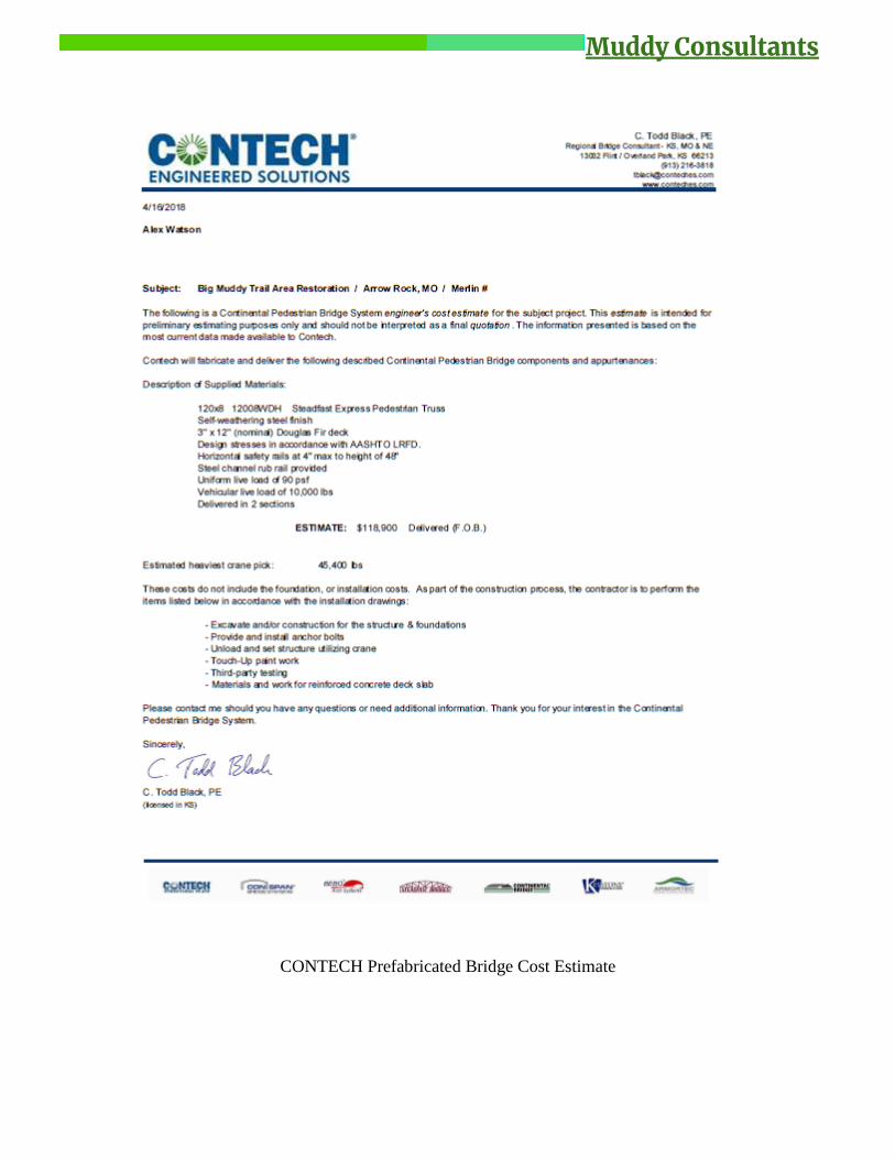
CONTECH Prefabricated Bridge Cost Estimate