Embed Size (px)
Citation preview
MTR Project ACCENT
T.O. van Staveren, NRG
A.J. de Koning, NRG
M. Davies, Frazer Nash Consultancy
September 18, 2013
2
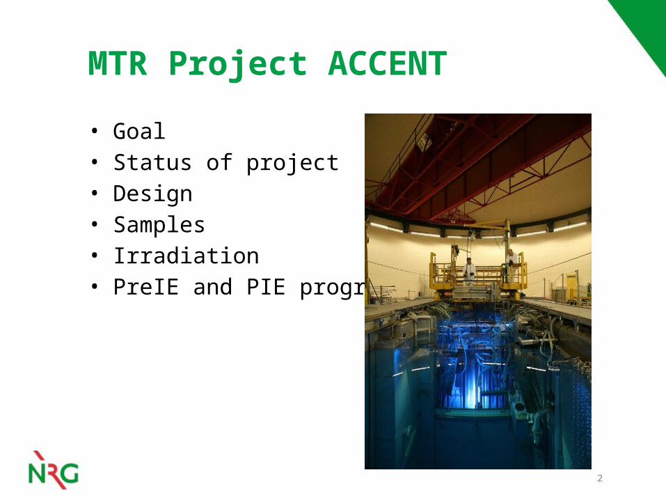
MTR Project ACCENT
• Goal• Status of project• Design• Samples• Irradiation• PreIE and PIE program

3
MTR Project ACCENT
• MTR: Materials Test Reactor• ACCENT: AGR Carbon Creep experimENT• Goal: Provide irradiation creep data on
(radiolytically oxidised) graphite– Input to models that predict graphite property changes
for EDF Energy Advanced Gas-cooled Reactors

4
Plan
• Irradiate graphite samples at high temperature under stress in the High Flux Reactor in Petten
• Perform multiple irradiation and post-irradiation characterisation stages to determine graphite properties at different dpa values
• Load virgin and radiolytically oxidised samples to determine irradiation creep behaviour at low / high neutron dose and weight loss

5
Project status
Conceptual design
Detailed design
Sample machining Pre-characterisation
Assembly and commissioning
Phase I Irradiation: 1 cycle with ~0.7 dpa
increment
Phase I Post-irradiation characterisation
Assembly and commissioning
Phase II Irradiation: 6 cycles with ~4 dpa
increment

6
Project status
Program on schedule: Start of design phase: mid-2012 Machining of radiolytically oxidised
specimens: February 2013 PreIE: Spring 2013 Module assembly: June 2013 Phase I Irradiation: July 2013 PIE: August / September 2013• Assembly Phase II: October 2013• Phase II irradiation: November 2013

7
Design
• Samples loaded in 6 modules• Instrumented holder for
modules with 24 thermocouples
• Sample target temperature: 420°C
• 10 MPa on stressed samples applied by gas filled bellows
• Samples under inert atmosphere

8
• Instrumented holder with 24 thermocouples → online temperature monitoring
• Temperature controlled by He/Ne gas mixture in 2nd containment
• SiC temperature monitors → post mortem temperature analysis of samples and bellows
Temperature control

9
Bellow system
• 4 samples per module• 2 samples under stress• Helium gas filled bellows• 10 MPa reached when
experiment is at temperature– Irradiation temperature at
bellows determines load on samples
• Filler and pressure parts for articulation and heat isolation
600mm
750mm
75mm
CL core 3
00mm
Bellow
Pressure part
Sample

10
Samples
• 24 samples in 6 modules– Two paired samples per module– One sample in a pair is loaded to 10 MPa
• Target samples give ‘3 Experiments’– Virgin Gilso graphite → ‘Experiment 2’– Radiolytically oxidised graphite at intermediate neutron
dose and weight loss (ex-Blackstone) → ‘Experiment 3’– Radiolytically oxidised graphite at high neutron dose
and weight loss (ex-AGR, ex-Blackstone) → ‘Experiment 1’

11
Samples at start of Phase I
dpa
Dim
ensi
onal
cha
nge
(%)
2
Experiment 2: virgin graphite
3
Experiment 3: radiolytically oxidised graphite, ex-Blackstone
1Experiment 1: radiolytically oxidised graphite, ex-AGR and ex-Blackstone

Sample geometries
12
Experiment 1• Sample machined from flexure tested beams,
ex-AGR, ex-Blackstone• 6 x 6 x 5.5 mm• Max. weight loss 37%
Experiment 2• Virgin samples• 12.5 x 6 x 5.5 mm• Laser engraving on one side
Experiment 3• Samples machined from cylinders irradiated in
Blackstone Phase I• 11.8 x 6 x 5.5 mm• Max. weight loss 8%

Sample machining (EXP 1)
• Samples radiolytically oxidised in AGR and High Flux Reactor Petten Blackstone irradiation
• Flexural tested beams, fracture surface ground back to give specimen pairs
• Marking of specimen needed to guarantee maintaining orientation relationship: grinding of corner
13

Pre-characterisation
14
Pre-stress testing
Photography Dimensions Mass CTE (3 directions) DYM (3 directions) Electrical resistivity ‘Standard’ XRD XRD texture Tomography
10 MPa
Loading samples to 10 MPa
DIC data recording
Photography Dimensions Mass CTE (3 directions) DYM (3 directions) Electrical resistivity ‘Standard’ XRD XRD texture Tomography
Before pre-stress testing
After pre-stress testing

15
Assembly
• Module parts and radioactive samples assembled in glove box
• Bellows pressurised with helium• Orbital welding of modules• Leak tightness testing

16
Phase I irradiation
• Irradiation from 13 July to 6 August 2013• dpa target reached: 0.7 dpa• Stable temperatures throughout irradiation• Analysis SiC temperature monitor ongoing
– Anneal SiC monitors at increasing temperatures– Measure electrical resistivity of SiC after each
annealing step

17
Dismantling
• Modules punctured to check for leaking of modules and bellows during irradiation
• Modules opened with milling machine in hot cell• Samples successfully retrieved from modules in
hot cell

18
PIE
• Started beginning of August• End: last week • Measurements:
– Photography– Dimensions– Mass– CTE– DYM– Electrical resistivity– ‘Standard’ XRD– XRD texture– Tomography
• Results…

19
Next steps
• Continue assessment of Phase I irradiation– Analysis of SiC temperature monitor sets– Analysis of neutron dosimetry sets
• Report post-irradiation characterisation measurements
• Assemble ACCENT Phase II irradiation experiment
• Start Phase II irradiation

20
Conclusions
• Successfull machining and pre-characterisation of radiolytically oxidised graphite samples
• Phase I irradiation completed:• dpa target reached• Stable temperatures throughout irradiation• Confirmation of irradiation temperature on-going
• Successfull completion of PIE measurements• Project on schedule for Phase II irradiation