Embed Size (px)
Citation preview

Data Acquisition: Building an MTConnect Adapter
• Dave Wickelhaus • Xiqun Wang, Ph.D. • TechSolve, Inc.

• Founding Sponsor of MTConnect Institute • NIST Manufacturing Extension Partnership (MEP) Affiliate • Ohio Edison Technology Center • Provider of Viz Suite of MTConnect®-compatible Adapters and Asset
Visualization Software • Advanced Machining Lab: Machining R&D, Problem Solving, Part Cost Reduction
and Comparative Testing • Dave Wickelhaus, Machining Systems Engineer • Xiqun Wang Ph.D, Machining Research Engineer
www.TechSolve.org
Agenda • Overview of MTConnect • Adapter Basics • Adapter Open Source Frameworks for
MTConnect • Building an Adapter using the C# Framework • Lab – Build an Adapter for MTConnect
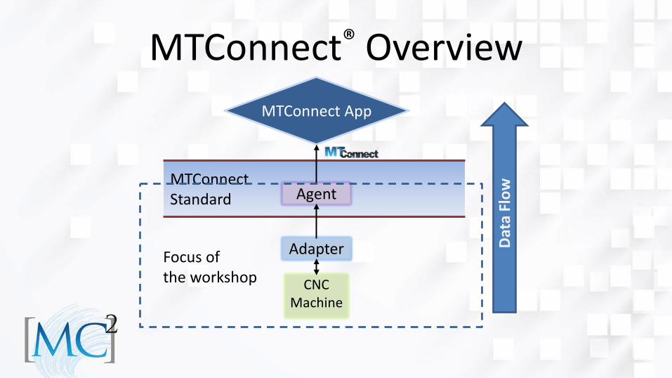
MTConnect Standard
MTConnect® Overview
Agent
Adapter
CNC Machine
MTConnect App
Dat
a Fl
ow
Focus of the workshop
What is an Adapter? • The Adapter is the liaison between the machine
control (or other devices such as sensors) and the MTConnect Agent
• The Adapter has two primary functions: – get information about the device’s current state such
as Controller Mode, Axis position, etc… – send the data to the MTConnect Agent
• The Adapter can be a simple software application or a combination of software and hardware – Hardware and Software examples: a device that plugs into the CNC I/O bus data acquisition unit that picks up signals from CNC’s
relay points
• Adapters may also be used to collect data from sensors such as Accelerometers or Human Input Devices (HIDs) that supply supplemental information relevant to the operation of the machine
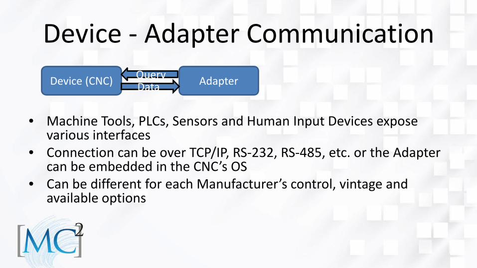
Device - Adapter Communication
• Machine Tools, PLCs, Sensors and Human Input Devices expose
various interfaces • Connection can be over TCP/IP, RS-232, RS-485, etc. or the Adapter
can be embedded in the CNC’s OS • Can be different for each Manufacturer’s control, vintage and
available options
Device (CNC) Adapter Data Query
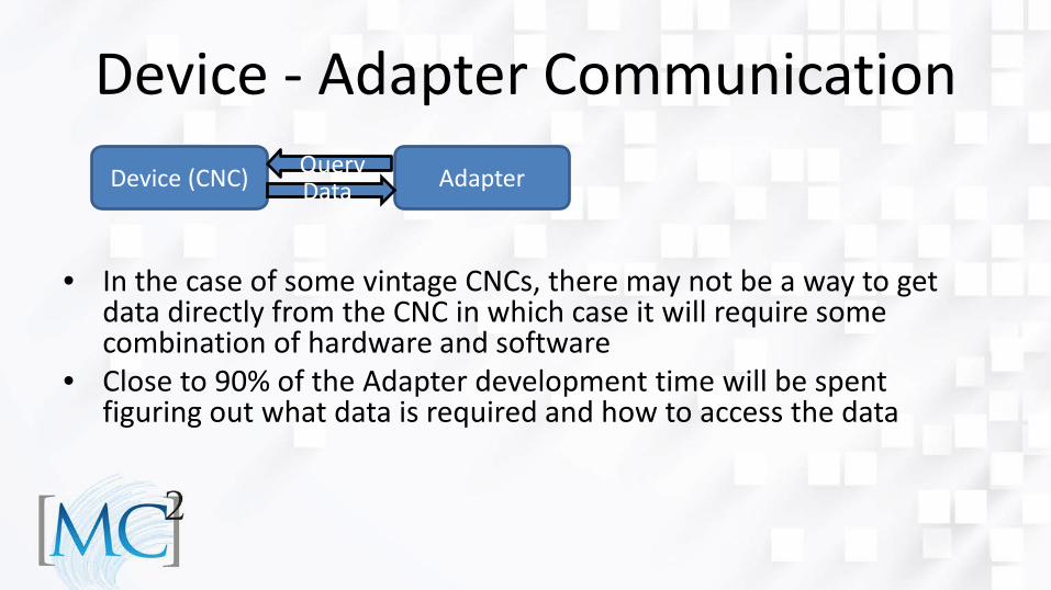
Device - Adapter Communication
• In the case of some vintage CNCs, there may not be a way to get
data directly from the CNC in which case it will require some combination of hardware and software
• Close to 90% of the Adapter development time will be spent figuring out what data is required and how to access the data
Device (CNC) Adapter Data Query
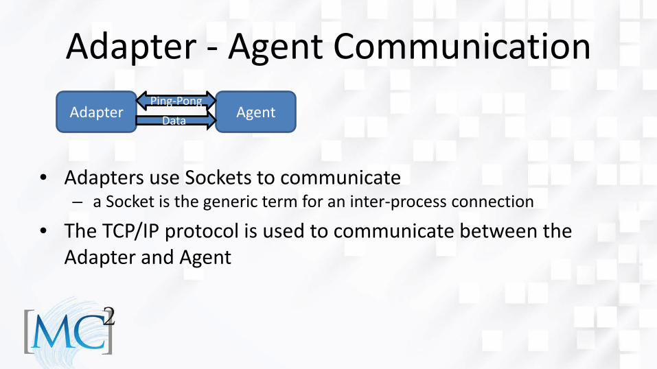
Adapter - Agent Communication
• Adapters use Sockets to communicate
– a Socket is the generic term for an inter-process connection
• The TCP/IP protocol is used to communicate between the Adapter and Agent
Adapter Agent Data Ping-Pong
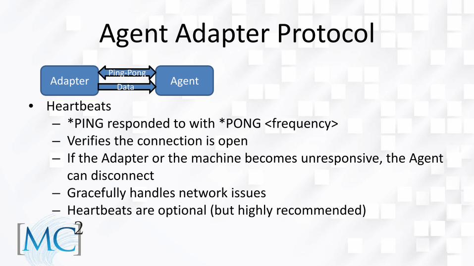
Agent Adapter Protocol
• Heartbeats – *PING responded to with *PONG <frequency> – Verifies the connection is open – If the Adapter or the machine becomes unresponsive, the Agent
can disconnect – Gracefully handles network issues – Heartbeats are optional (but highly recommended)
Adapter Agent Data Ping-Pong
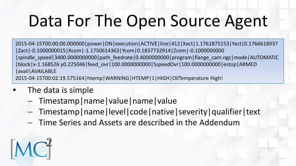
• The data is simple − Timestamp|name|value|name|value − Timestamp|name|level|code|native|severity|qualifier|text − Time Series and Assets are described in the Addendum
Data For The Open Source Agent 2015-04-15T00:00:00.000000|power|ON|execution|ACTIVE|line|412|Xact|1.1761875153|Yact|0.1766618937 |Zact|-0.1000000015|Xcom|-1.1750614363|Ycom|0.1837732914|Zcom|-0.1000000000 |spindle_speed|3400.0000000000|path_feedrate|0.4000000000|program|flange_cam.ngc|mode|AUTOMATIC |block|x-1.168526 y0.225046|feed_ovr|100.0000000000|SspeedOvr|100.0000000000|estop|ARMED |avail|AVAILABLE 2015-04-15T00:02:19.575164|htemp|WARNING|HTEMP|1|HIGH|OilTemperature High!
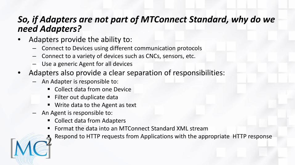
So, if Adapters are not part of MTConnect Standard, why do we need Adapters? • Adapters provide the ability to:
– Connect to Devices using different communication protocols – Connect to a variety of devices such as CNCs, sensors, etc. – Use a generic Agent for all devices
• Adapters also provide a clear separation of responsibilities: – An Adapter is responsible to:
Collect data from one Device Filter out duplicate data Write data to the Agent as text
– An Agent is responsible to: Collect data from Adapters Format the data into an MTConnect Standard XML stream Respond to HTTP requests from Applications with the appropriate HTTP response
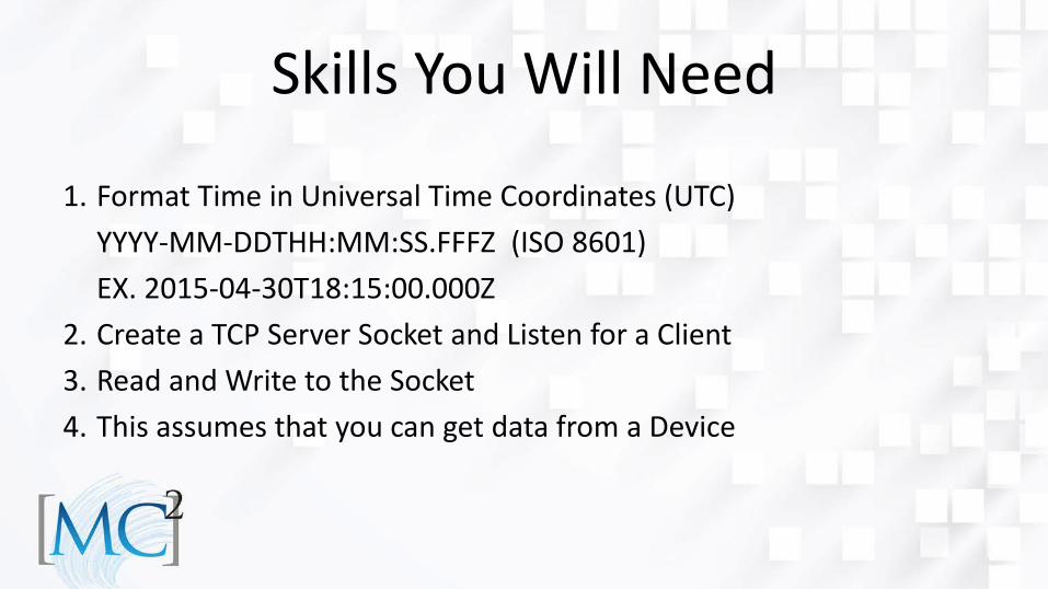
Skills You Will Need
1. Format Time in Universal Time Coordinates (UTC) YYYY-MM-DDTHH:MM:SS.FFFZ (ISO 8601) EX. 2015-04-30T18:15:00.000Z
2. Create a TCP Server Socket and Listen for a Client 3. Read and Write to the Socket 4. This assumes that you can get data from a Device
Simpler Yet • There is no need to master those skills • There are frameworks in C++, C#, Ruby, and
Python which to handle those items • This Lab exercise will utilize the C# Framework
How Do Frameworks Help? • Frameworks provide:
– Communication and protocols – Data formatting – Detection of changed Data Items – Support for MTConnect Data Types
Events Samples Conditions Message Time Series Assets
Data Items are covered in Part 2 of the Standard Assets are covered in Part 4 of the Standard
Programmer’s Responsibilities • The Programmer is responsible for:
– Determining the controller configuration – Creating a Data Item for each parameter to monitored – Gathering data periodically or on an event callback – Sending only changed values
Adapter Design Approach • Gather the information for the following components:
– Controller & Paths – Axes – Systems – Cutting Tools
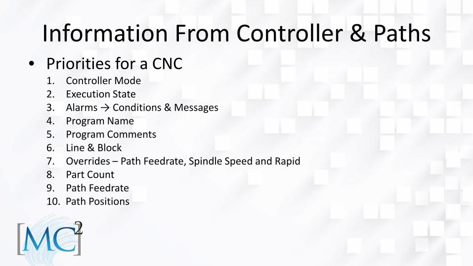
Information From Controller & Paths • Priorities for a CNC
1. Controller Mode 2. Execution State 3. Alarms → Conditions & Messages 4. Program Name 5. Program Comments 6. Line & Block 7. Overrides – Path Feedrate, Spindle Speed and Rapid 8. Part Count 9. Path Feedrate 10. Path Positions

Information About Axis & Spindles • Priorities:
1. Position & Angle 2. Spindle Speed 3. Loads 4. Alarms 5. Temperature

Systems • There are usually a few conditions associated with a few
special alarms – Coolant – Hydraulics – Pneumatics – Electrical
Getting The Controller Mode • Let’s use the FANUC FOCAS library as an example since there
is an open source C++ version of the Adapter: – For the Controller Mode use the FOCAS ODBST status
structure and make a call to the cnc_statinfo function
Mapping The Controller Mode • The “aut” byte returned as part of the ODBST data structure has
the following definitions: – status.aut = 5 or 6 indicates the CNC is in MANUAL mode – status.aut = 0 or 3 indicates the CNC is in MDI or EDIT mode – Otherwise the CNC is in the AUTOMATIC mode
• This is how some of the basic Controller Modes are mapped for the FANUC
Community • Wiki for implementation and behavior
http://mtcup.org/wiki/Main_Page • Example:
– Current best practice for EDIT mode is MANUAL (EDIT and BACKGROUND will be implemented in future versions)
– When motion is HOLD or WAIT, then Execution is INTERRUPTED
– Etc…
Alarms And Conditions • Alarms and Conditions require special handling • Some important facts:
– Multiple conditions can be active for the same type at the same time
– Conditions are unique by type and native code This is an implementation decision
– One or more conditions can be cleared at the same time
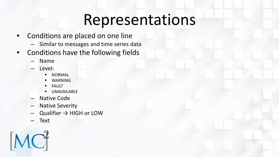
Representations • Conditions are placed on one line
– Similar to messages and time series data • Conditions have the following fields
– Name – Level:
NORMAL WARNING FAULT UNAVAILABLE
– Native Code – Native Severity – Qualifier → HIGH or LOW – Text

How To Handle Alarm Lists?? • Tools implement Mark and Sweep to collect alarms that are
no longer active • For every alarm in the list, add it to the condition of that type • If an alarm is not added, it is cleared
– An add marks active alarms, then the sweep finds all alarms that are not marked and removes them
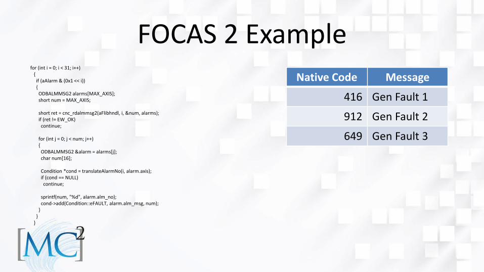
FOCAS 2 Example for (int i = 0; i < 31; i++) { if (aAlarm & (0x1 << i)) { ODBALMMSG2 alarms[MAX_AXIS]; short num = MAX_AXIS; short ret = cnc_rdalmmsg2(aFlibhndl, i, &num, alarms); if (ret != EW_OK) continue; for (int j = 0; j < num; j++) { ODBALMMSG2 &alarm = alarms[j]; char num[16]; Condition *cond = translateAlarmNo(i, alarm.axis); if (cond == NULL) continue; sprintf(num, "%d", alarm.alm_no); cond->add(Condition::eFAULT, alarm.alm_msg, num); } } }
Native Code Message
416 Gen Fault 1
912 Gen Fault 2
649 Gen Fault 3
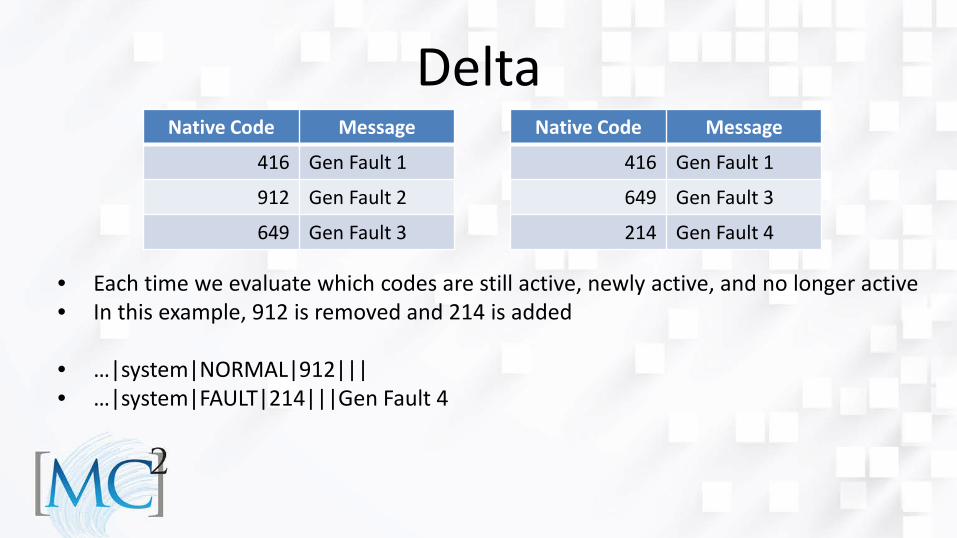
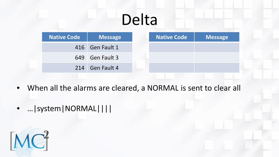
Delta
• Each time we evaluate which codes are still active, newly active, and no longer active • In this example, 912 is removed and 214 is added • …|system|NORMAL|912||| • …|system|FAULT|214|||Gen Fault 4
Native Code Message
416 Gen Fault 1
649 Gen Fault 3
214 Gen Fault 4
Native Code Message
416 Gen Fault 1
912 Gen Fault 2
649 Gen Fault 3
Delta
• When all the alarms are cleared, a NORMAL is sent to clear all • …|system|NORMAL||||
Native Code Message
Native Code Message
416 Gen Fault 1
649 Gen Fault 3
214 Gen Fault 4
Simple Conditions • If the data source sends an event when the alarms starts and
stops you can use a simple condition • A simple condition requires an explicate clear when the
condition is no longer active
Make the Adapter Dynamic • To make the Adapter dynamic it has to discover the axes and
paths by interrogating the Controller • It then uses that information to dynamically configure the
Adapter to get data from these components • Now we have a dynamic Adapter – match the Agent’s
configuration to what we discover and it works across machine tool configurations
• The open source FANUC Adapter is an example of self-configuring multipath and axis
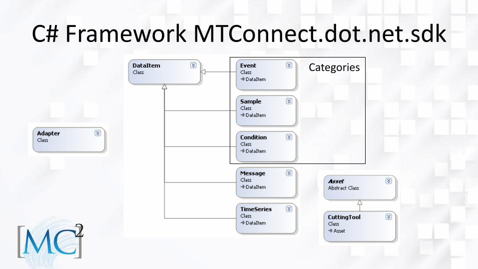
C# Framework MTConnect.dot.net.sdk Categories
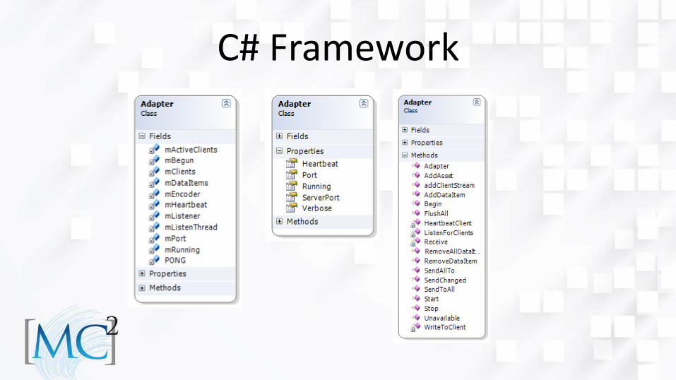
C# Framework
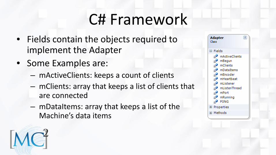
C# Framework • Fields contain the objects required to
implement the Adapter • Some Examples are:
– mActiveClients: keeps a count of clients – mClients: array that keeps a list of clients that
are connected – mDataItems: array that keeps a list of the
Machine’s data items
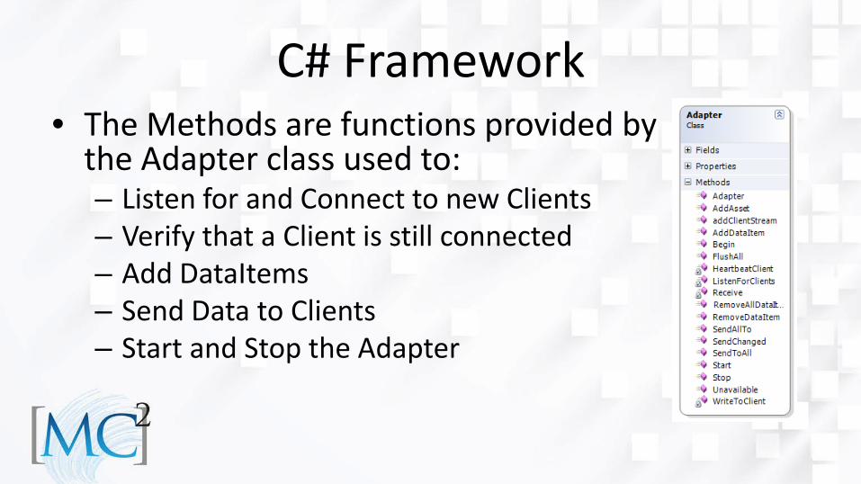
C# Framework • The Methods are functions provided by
the Adapter class used to: – Listen for and Connect to new Clients – Verify that a Client is still connected – Add DataItems – Send Data to Clients – Start and Stop the Adapter
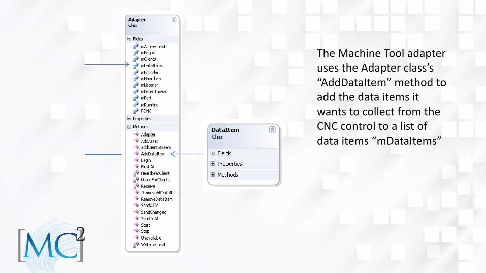
The Machine Tool adapter uses the Adapter class’s “AddDataItem” method to add the data items it wants to collect from the CNC control to a list of data items “mDataItems”
Adapter Lab 1. Availability 2. Emergency Stop event 3. Controller Mode and Execution events 4. Program and Message events 5. Position and Load samples 6. Conditions Time Permitting 7. Cutting Tool 8. Time Series 9. MTConnect Extensibility
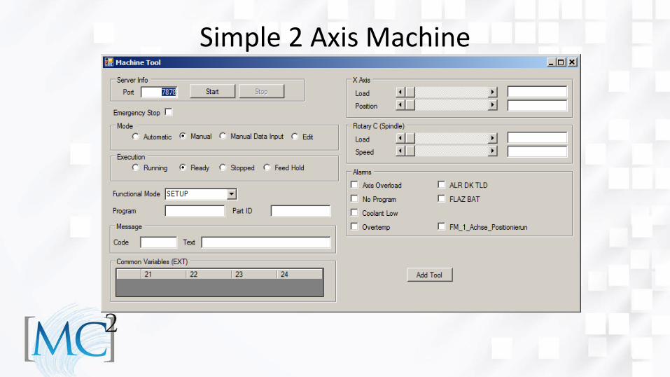
Simple 2 Axis Machine
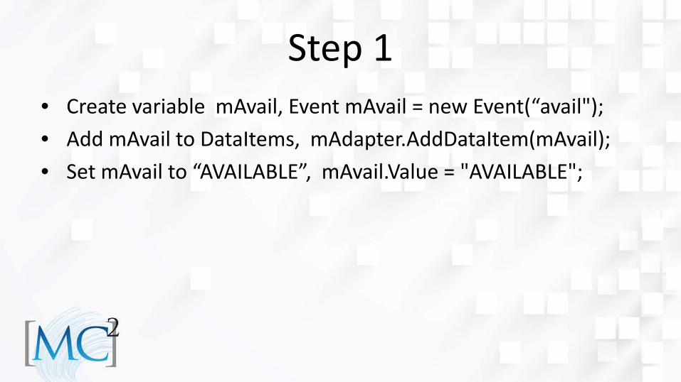
Step 1 • Create variable mAvail, Event mAvail = new Event(“avail"); • Add mAvail to DataItems, mAdapter.AddDataItem(mAvail); • Set mAvail to “AVAILABLE”, mAvail.Value = "AVAILABLE";
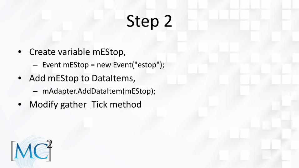
Step 2 • Create variable mEStop,
– Event mEStop = new Event("estop");
• Add mEStop to DataItems, – mAdapter.AddDataItem(mEStop);
• Modify gather_Tick method
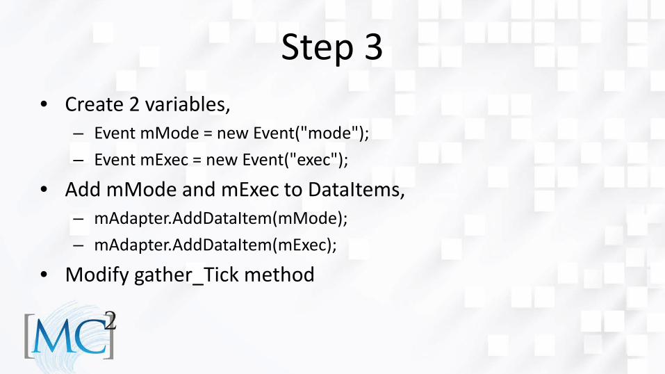
Step 3 • Create 2 variables,
– Event mMode = new Event("mode"); – Event mExec = new Event("exec");
• Add mMode and mExec to DataItems, – mAdapter.AddDataItem(mMode); – mAdapter.AddDataItem(mExec);
• Modify gather_Tick method
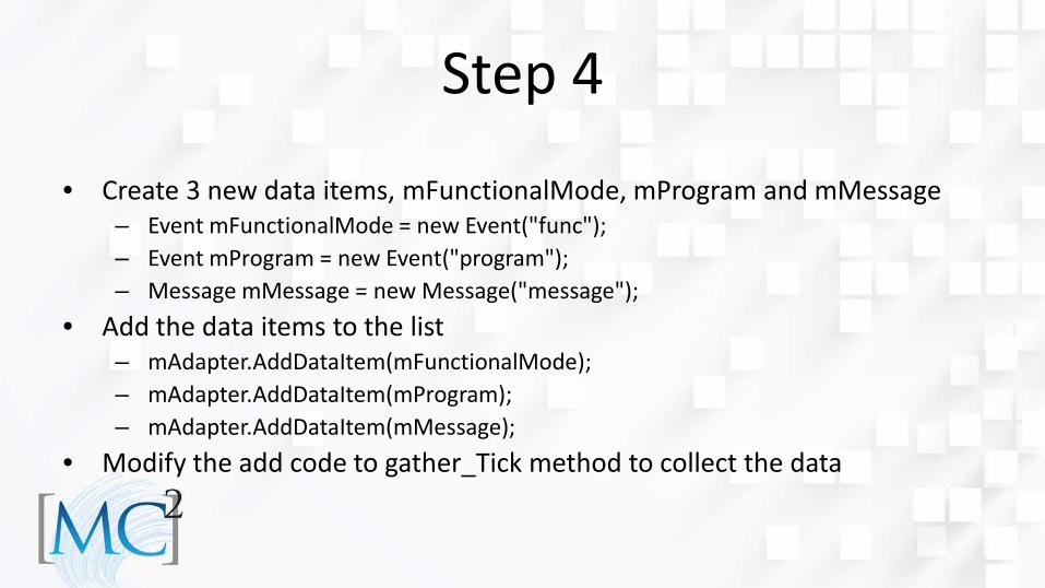
Step 4
• Create 3 new data items, mFunctionalMode, mProgram and mMessage – Event mFunctionalMode = new Event("func"); – Event mProgram = new Event("program"); – Message mMessage = new Message("message");
• Add the data items to the list – mAdapter.AddDataItem(mFunctionalMode); – mAdapter.AddDataItem(mProgram); – mAdapter.AddDataItem(mMessage);
• Modify the add code to gather_Tick method to collect the data
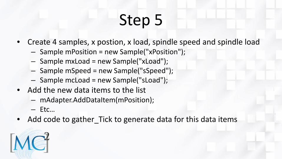
Step 5 • Create 4 samples, x postion, x load, spindle speed and spindle load
– Sample mPosition = new Sample("xPosition"); – Sample mxLoad = new Sample("xLoad"); – Sample mSpeed = new Sample("sSpeed"); – Sample mcLoad = new Sample("sLoad");
• Add the new data items to the list – mAdapter.AddDataItem(mPosition); – Etc…
• Add code to gather_Tick to generate data for this data items
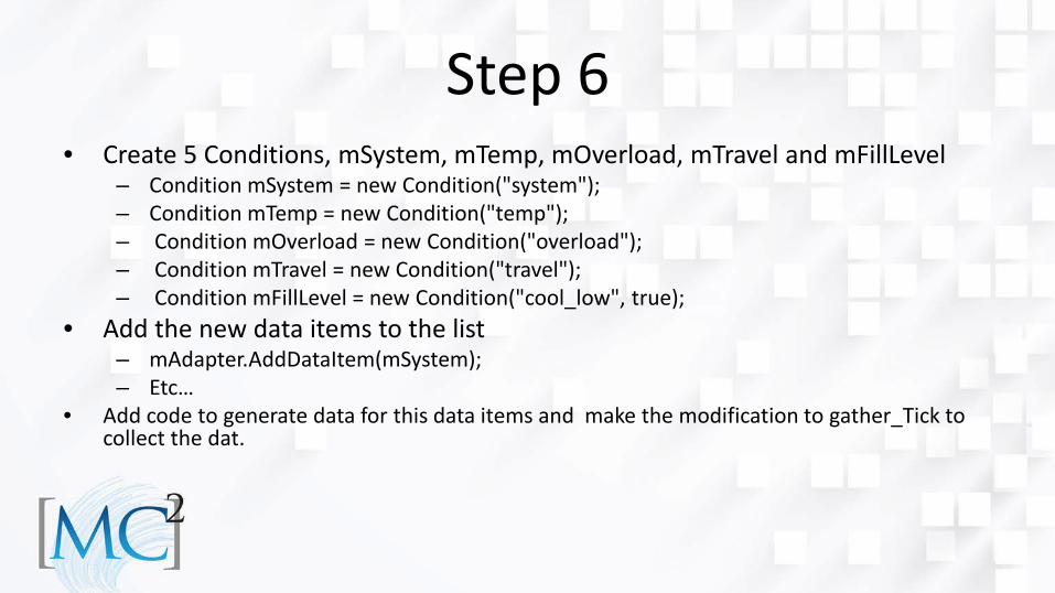
Step 6 • Create 5 Conditions, mSystem, mTemp, mOverload, mTravel and mFillLevel
– Condition mSystem = new Condition("system"); – Condition mTemp = new Condition("temp"); – Condition mOverload = new Condition("overload"); – Condition mTravel = new Condition("travel"); – Condition mFillLevel = new Condition("cool_low", true);
• Add the new data items to the list – mAdapter.AddDataItem(mSystem); – Etc…
• Add code to generate data for this data items and make the modification to gather_Tick to collect the dat.

Step 7 • Add Cutting Tool Asset
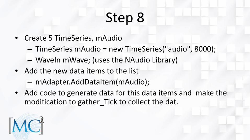
Step 8 • Create 5 TimeSeries, mAudio
– TimeSeries mAudio = new TimeSeries("audio", 8000); – WaveIn mWave; (uses the NAudio Library)
• Add the new data items to the list – mAdapter.AddDataItem(mAudio);
• Add code to generate data for this data items and make the modification to gather_Tick to collect the dat.
Step 9 • MTConnect Extensibility example.

Questions? • Contact us:
Thanks • Will Sobel, System Insights
– This presentation and lab are based on Will’s previous MC2 workshops.
• Hilena Hailu, AMT – Support in organizing this presentation.

Addendum
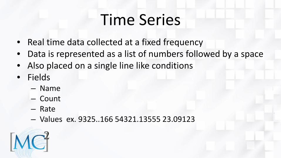
Time Series • Real time data collected at a fixed frequency • Data is represented as a list of numbers followed by a space • Also placed on a single line like conditions • Fields
– Name – Count – Rate – Values ex. 9325..166 54321.13555 23.09123
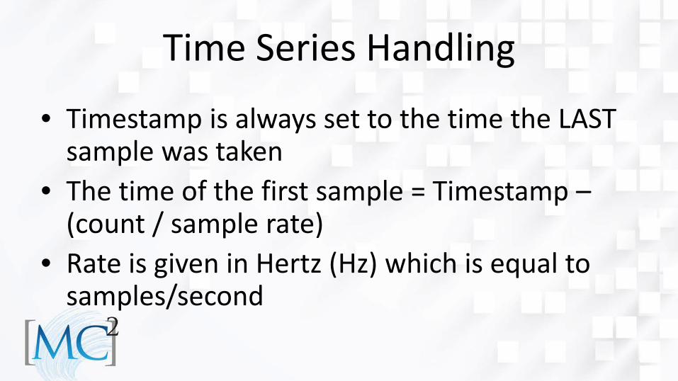
Time Series Handling
• Timestamp is always set to the time the LAST sample was taken
• The time of the first sample = Timestamp –(count / sample rate)
• Rate is given in Hertz (Hz) which is equal to samples/second
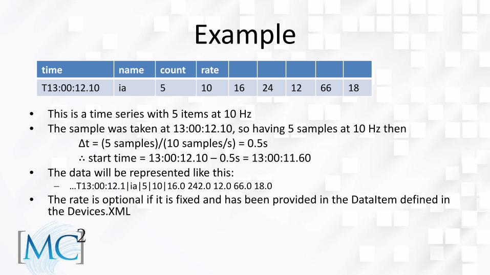
Example
• This is a time series with 5 items at 10 Hz • The sample was taken at 13:00:12.10, so having 5 samples at 10 Hz then Δt = (5 samples)/(10 samples/s) = 0.5s ∴ start time = 13:00:12.10 – 0.5s = 13:00:11.60 • The data will be represented like this:
− …T13:00:12.1|ia|5|10|16.0 242.0 12.0 66.0 18.0 • The rate is optional if it is fixed and has been provided in the DataItem defined in
the Devices.XML
time name count rate
T13:00:12.10 ia 5 10 16 24 12 66 18
Relative Time • New feature to handle sensors without wallclock time • Instead of giving a timestamp provide a relative clock
tick in milliseconds • Agent will use it’s own time then compute the offsets
based on the relative time • Maintains consistent spacing between samples and
allows for data analysis
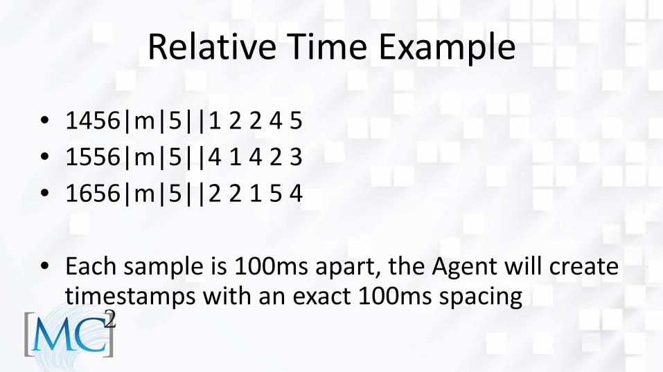
Relative Time Example
• 1456|m|5||1 2 2 4 5 • 1556|m|5||4 1 4 2 3 • 1656|m|5||2 2 1 5 4
• Each sample is 100ms apart, the Agent will create
timestamps with an exact 100ms spacing
Assets • Cutting Tool is currently the only asset we
support, but others can be handled by the Agent as well
• The Agent now supports a multi-line document for assets
• It sends an XML document with an asset as the content (can be multiline)
Asset Representation
• Use the special name @ASSET@ to signify an asset is to follow
• Next the Asset ID – All assets have a unique id
• Specify the type: “CuttingTool” • And the data …..
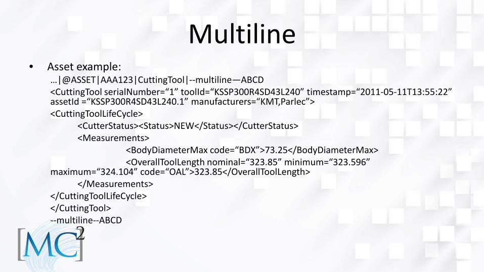
Multiline • Asset example:
…|@ASSET|AAA123|CuttingTool|--multiline—ABCD <CuttingTool serialNumber=“1” toolId=“KSSP300R4SD43L240” timestamp=“2011-05-11T13:55:22” assetId =“KSSP300R4SD43L240.1” manufacturers=“KMT,Parlec”> <CuttingToolLifeCycle> <CutterStatus><Status>NEW</Status></CutterStatus> <Measurements> <BodyDiameterMax code=“BDX”>73.25</BodyDiameterMax> <OverallToolLength nominal=“323.85” minimum=“323.596” maximum=“324.104” code=“OAL”>323.85</OverallToolLength> </Measurements> </CuttingToolLifeCycle> </CuttingTool> --multiline--ABCD
Alternative
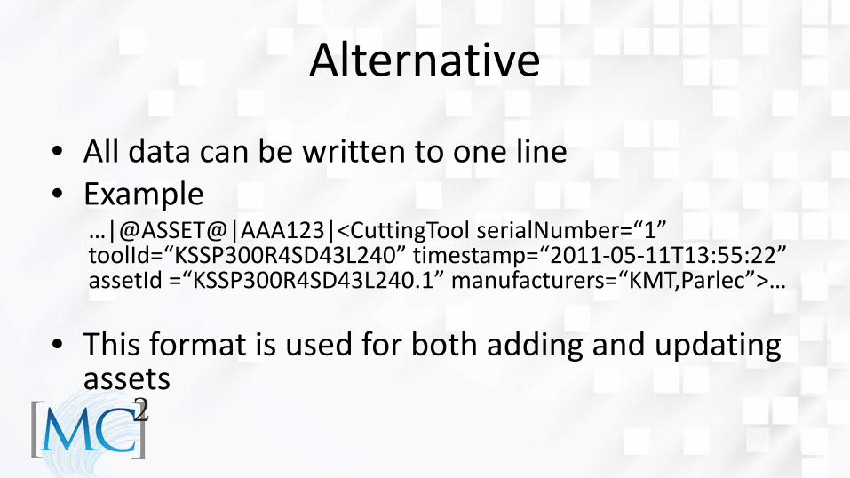
• All data can be written to one line • Example
…|@ASSET@|AAA123|<CuttingTool serialNumber=“1” toolId=“KSSP300R4SD43L240” timestamp=“2011-05-11T13:55:22” assetId =“KSSP300R4SD43L240.1” manufacturers=“KMT,Parlec”>…
• This format is used for both adding and updating assets
Adding Other Assets
• Specify another asset type and provide full asset document
• Read Part 4 of the MTConnect Standard for full details on XML formats
• Cutting Tool is parsed and reformatted by the Agent to ensure proper representation