Embed Size (px)
Citation preview

A HIERARCHICAL TASK ANALYSIS SOFTWARE TOOL BASED ON
THE MODEL-VIEW-CONTROLLER ARCHITECTURE PATTERN
By Ateet Vora
A Thesis submitted to the
Graduate School-New Brunswick
Rutgers, The State University of New Jersey
in partial fulfillment of the requirements
for the degree of
Master of Science
Graduate Program in Electrical and Computer Engineering
Written under the direction of
Prof. Ivan Marsic
and approved by
________________________
________________________
________________________
New Brunswick, New Jersey
January, 2011

ii
ABSTRACT OF THE THESIS
A Hierarchical Task Analysis Software Tool Based on the Model-View-Controller
Architecture Pattern
By ATEET VORA
Thesis Director:
Prof. Ivan Marsic
Hierarchical Task Analysis is a systematic method of describing how work is organized
in order to meet the overall objective of the job. It involves identifying, in a top-down
approach, the overall goal of the task, then the various sub-tasks and then the conditions
under which they should be carried out to achieve the goal.
In this thesis, we set out to design and develop a simple, robust and flexible
hierarchical task analysis software tool. We provide an intuitive user interface to create
hierarchical tasks, additionally we provide features which are not available in existing
tools like - the ability to reuse the task analysis data as templates, import or export Xml,
store task and sub-tasks for reusability. These new features serve to improve time
efficiency, compatibility with applications developed using other platforms and the ease
with which the tool can be extended by adding new features.
We use the Model-View-Controller (MVC) software architecture pattern since it
is suitable for applications with a user-interface and at the same time aids in developing
highly scalable and extensible applications.
We produce simulation results to project the functionalities of our tool and also
discuss some non-functional requirements, such as usability, scalability and extensibility.

iii
Acknowledgement
First of all, I would sincerely like to thank my advisor Prof. Ivan Marsic for his constant
guidance and support throughout the duration of my thesis work. He has provided me a
wonderful opportunity to work in the field of my interest, and at the same time, helped
me make the correct decisions and generate results.
I would also like to thank all my friends at Rutgers University from the past three
years who have helped me become a better researcher. I would like to thank my family
for providing me with the strength and support to remain dedicated to my research work.
Last but not the least, I would like to thank the love of my life, Surbhi, for the
constant motivation and help in shaping my master’s thesis work. She has been my
strength and my guide; I would like to dedicate my work to her.

iv
Table of Contents
ABSTRACT OF THE THESIS ....................................................................................................... ii
Acknowledgement .......................................................................................................................... iii
1. Introduction .............................................................................................................................. 1
2. Related Work ........................................................................................................................... 6
2.1 Hierarchical Task Analysis Tools .................................................................................... 6
2.1.1 The HTA Tool .......................................................................................................... 6
2.1.2 VIP Task Manager ................................................................................................... 7
2.1.3 TaskAnyone ............................................................................................................. 8
2.1.4 TaskArchitect ........................................................................................................... 8
2.2 Software Patterns ........................................................................................................... 11
2.2.1 Properties ............................................................................................................... 11
2.2.2 Categories of Patterns ............................................................................................ 13
2.2.3 Architectural Patterns ............................................................................................. 14
2.2.4 Model-View-Controller Architecture..................................................................... 15
3 Technical Approach ............................................................................................................... 20
3.1 Variations of the MVC Pattern ...................................................................................... 22
3.1.1 The Passive MVC Model ....................................................................................... 23
3.1.2 The Active MVC Model ........................................................................................ 24
3.1.3 The Observer Model .............................................................................................. 24
4 Implementation ...................................................................................................................... 29
4.1 Objective ........................................................................................................................ 30
4.2 Requirement Analysis .................................................................................................... 31
4.3 Architectural Design ...................................................................................................... 32
4.4 Coding ............................................................................................................................ 47

v
4.5 Testing ........................................................................................................................... 48
4.6 Release ........................................................................................................................... 49
5 Results .................................................................................................................................... 51
5.1 Functional Requirements ............................................................................................... 51
5.2 Non-Functional Requirements ....................................................................................... 52
5.2.1 Usability ................................................................................................................. 53
5.2.2 Open Source ........................................................................................................... 54
5.2.3 Scalability .............................................................................................................. 54
5.2.4 Extensibility ........................................................................................................... 56
6. Conclusion ............................................................................................................................. 60
7. Future Work ........................................................................................................................... 62
Requirement Analysis Document .............................................................................................. 63
Wireframes: ............................................................................................................................... 66
Appendix B .................................................................................................................................... 76
Appendix C .................................................................................................................................... 78
Tree Architect Application Screenshots .................................................................................... 78
Process Maps ............................................................................................................................. 91
References .................................................................................................................................... 100

vi
Table of Figures
Figure 1: Model View Controller .................................................................................................. 16
Figure 2: Passive MVC Model [12] ............................................................................................... 23
Figure 3: Active MVC Model [13] ................................................................................................ 24
Figure 4: The Observer Model [14] ............................................................................................... 25
Figure 5: Technical Architecture ................................................................................................... 37
Figure 6: Tree Architect Class Diagram ........................................................................................ 45
Figure 7: Basic Tree Control (Currently used in the system) ........................................................ 58
Figure 8: New View ....................................................................................................................... 59
Figure 9: VIBlend tree view .......................................................................................................... 59

vii
List of Tables
Table 1: View Classes ....................................................................................................... 34
Table 2: Controller Classes ............................................................................................... 38
Table 3: Model Classes - Data Access Layer ................................................................... 42
Table 4: Model Classes - Business Layer ......................................................................... 43
Table 5: Functional Requirements .................................................................................... 63

1
1. Introduction
Task Analysis (TA) analyses what a user is required to do in terms of actions and/or
cognitive processes to achieve a task. A detailed TA can be conducted to understand the
current system and the information that flows within it. These information flows are
important for the maintenance of the existing system and must be incorporated or
substituted in any new system.
Nearly all TA techniques provide as a minimum, a description of the observable
aspects of operator behavior at various levels of detail, together with some indications of
the structure of the task. These will be referred to as Action Oriented Approaches (AOA).
Other techniques focuses on the mental processes which underlie observable behavior
e.g. decision making and problem solving. These will be referred to as Cognitive
Approaches.
TA tools can be used to eliminate the preconditions that give rise to errors before
they occur. They can be used as an aid in the design stage of a new system, or in the
modification of an existing system. We shall keep focus on Hierarchical Task Analysis
(HTA) which belongs to the category of Action Oriented Approach and is the type of task
analysis our tool performs.
HTA is a systematic method of describing how work is organized in order to meet
the overall objective of the job. It involves identifying, in a top-down approach, the
overall goal of the task, then the various sub-tasks and then the conditions under which
they should be carried out to achieve the goal. In this way, complex planning tasks can be

2
represented as a hierarchy of operations – different things which people must do within a
system, and plans – the conditions which are necessary to undertake these operations.
HTA commences by stating the overall objective that the person has to achieve.
This is then re-described into a set of sub-operations and the plan specifying when these
operations are carried out. The plan is an essential component of HTA since it describes
the information sources that the worker must attend to, in order to signal the need for
various activities. Each sub operation can be re-described further, if the analyst requires,
again in terms of other operations and plans.
The question whether it is necessary to break down a particular operation to a
finer level depends on whether the analyst believes a significant error mode is likely to be
revealed by a more fine grained analysis.
Our efforts in trying to provide a tool which can perform hierarchical task
analysis are based on the advantages which can be offered to the analyst such as:
1. HTA is an economical method of gathering and organizing information since the
hierarchical description needs only to be developed up to the point where it is
needed for the purpose of analysis.
2. When used as an input to design, HTA allows functional objectives to be
specified at the higher levels of analysis prior to final decisions being made about
the hardware. This is important when allocating functions between personnel who
are responsible for the effective operation of the system.
3. HTA is best developed as collaboration between the task analyst and people
involved in operations. Thus, the analyst develops the description of the task in
3
accordance with the perceptions of line personnel who are responsible for
effective operation of the system.
4. HTA can be used as a starting point for various error analysis methods to examine
the error potential in the performance of the required operations.
Our aim in this thesis is to incorporate most of the qualities of hierarchical task
analysis mentioned above in our task analysis tool which allows analysts to freely apply
their creativity to the project at hand. There are a number of task analysis tools available
in the market which supports hierarchical task analysis, but we have planned to build a
tool which not only supports hierarchical task analysis, but can be used to perform
additional operations within the scope of task analysis.
Some of the additional features which we would like our tool to support are:
1. Provide a number of reusable templates to create task analysis flow diagrams,
including the provision to add more templates.
2. Ability to store newly added tasks, sub-tasks or state variables. This saves
tremendous amount of development time for the task analyst, since these can be
used as components to build a new hierarchical task.
3. Ability to import and export XML documents, which is a W3C Standard. It is
widely regarded as the future of the internet, since it is a standard which can
seamlessly integrate with any system.
4. Ability to connect our system with a data store like the Microsoft SQL Server
which would boast the storage capabilities of the tool and can be used to
integrate with other systems in a professional development environment.
4
5. Develop a standard XML Document Type Definition (DTD), since we will be
using an XML data source. This definition will help other applications to
understand and efficiently integrate with our HTA tool.
On successful implementation of these exciting new features we will increase the
capabilities and power of a hierarchical task analysis tool. This tool though simple, will
be packed with many more features than any other HTA tool freely available in the
market.
We would be facing challenges while designing and developing this application
because of a number of reasons, which being the inclusion of the set of new features
mentioned above. The design would also require our application to be lightweight,
extremely scalable, and able to integrate with other systems.
Because of the set of preferences like writing optimal code and developing reusable
programming components, we will be forced to consider the various design patterns
before developing the tool. Software design patterns are solution to a recurring software
problem. If this approach is followed we could be successful in developing the HTA tool
with the qualities discussed above.
The rest of the thesis is organized as described below. Chapter 2 discusses the prior
works in terms of architectures and design patterns developed, and various kinds of HTA
tools available in the open market. In Chapter 3, we provide a brief overview of the tools
and design pattern we will use to develop our tool. In Chapter 4, we shall describe how
exactly we implemented the software system based on our selection of the software
development process and methodology. In Chapter 5, we provide the results we have

5
achieved on successful completion of the thesis work. In the last chapter, we conclude by
summarizing the salient features of our work, and enumerate a few implementation
options as a part of future work for other researchers to improve the hierarchical task
analysis software tool.

6
2. Related Work
In this chapter, we shall have a look at the previous work accomplished in the two most
important categories related to our thesis work. Firstly, we will look at some of the TA
tools available in the market as of today and the various features they have to offer.
Next, we will also look into the various architecture design patterns available to
develop our software system. We will closely look into the Model View Controller
architecture pattern since it suits a software system which involves human computer
interface. We will also describe the variants of the MVC pattern and conclude with the
valid reasons on why we chose the MVC architecture pattern and also why a particular
variant of the pattern!
2.1 Hierarchical Task Analysis Tools
In this section we discuss the various task analysis software tools that have been
developed for both commercial and non-commercial purposes. In our discussion, we will
mention some of the salient features of these software tools and will end the discussion
with some of the shortcomings which we have addressed in our task analysis tool.
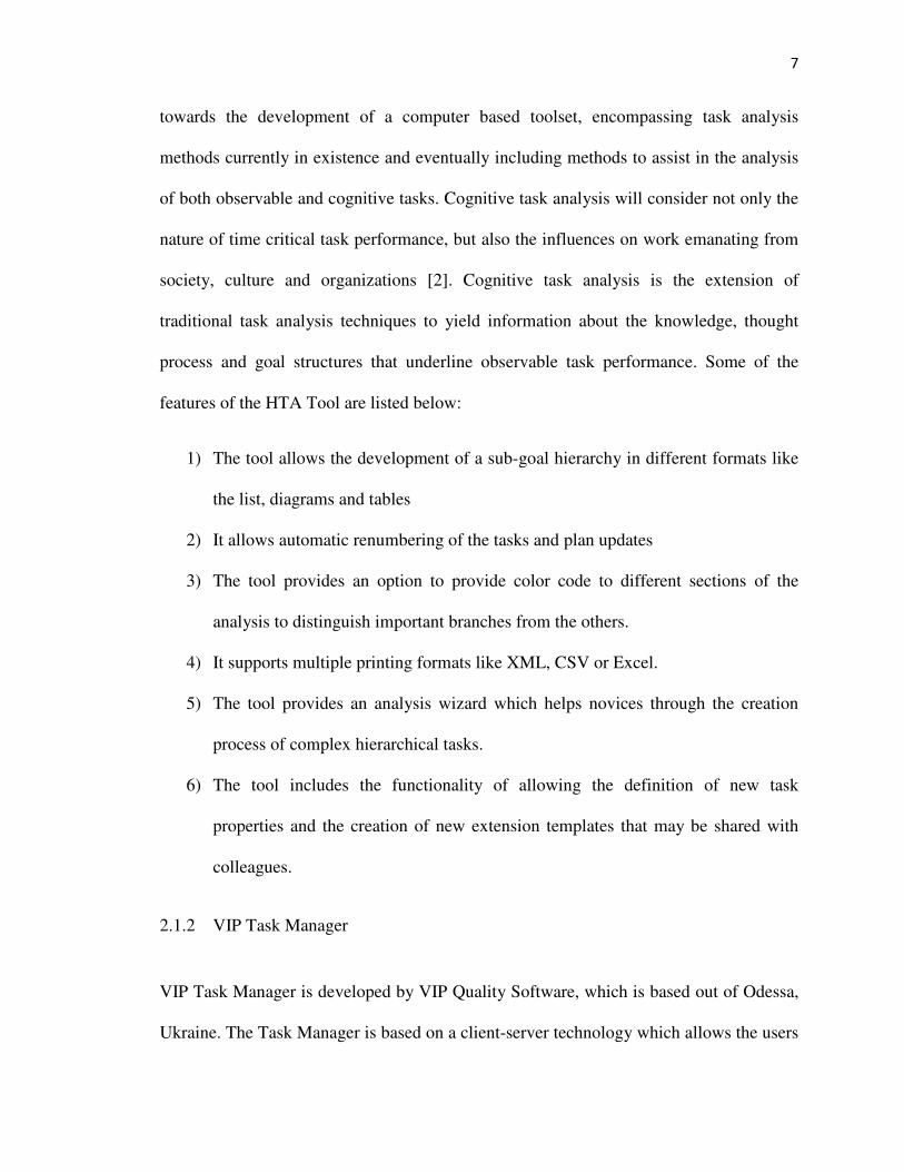
2.1.1 The HTA Tool
The HTA tool [1] was developed by The Human Factors Integration (HFI) Defense
Technology Center (DTC), which is an initiative by the UK Ministry of Defense. The
HTA tool was developed for non-commercial purposes. Traditionally, task analysis was
carried out with the erroneous use of pencil and paper. The HTA tool represents a start
7
towards the development of a computer based toolset, encompassing task analysis
methods currently in existence and eventually including methods to assist in the analysis
of both observable and cognitive tasks. Cognitive task analysis will consider not only the
nature of time critical task performance, but also the influences on work emanating from
society, culture and organizations [2]. Cognitive task analysis is the extension of
traditional task analysis techniques to yield information about the knowledge, thought
process and goal structures that underline observable task performance. Some of the
features of the HTA Tool are listed below:
1) The tool allows the development of a sub-goal hierarchy in different formats like
the list, diagrams and tables
2) It allows automatic renumbering of the tasks and plan updates
3) The tool provides an option to provide color code to different sections of the
analysis to distinguish important branches from the others.
4) It supports multiple printing formats like XML, CSV or Excel.
5) The tool provides an analysis wizard which helps novices through the creation
process of complex hierarchical tasks.
6) The tool includes the functionality of allowing the definition of new task
properties and the creation of new extension templates that may be shared with
colleagues.
2.1.2 VIP Task Manager
VIP Task Manager is developed by VIP Quality Software, which is based out of Odessa,
Ukraine. The Task Manager is based on a client-server technology which allows the users

8
to create a centralized database and keep all the information for hierarchical task analysis
available to all the users logged in to a single Local Area Network (LAN) [3]. The
various features of the tool are listed below:
1) It is a client-server type of software tool with a centralized database to store our
task analysis data.
2) The tool provides us with only two separate types of views to create our
hierarchical tasks, namely tree view and a panel view.
3) It allows us to set priority and order to the sub-tasks, and also allows the user to
update the task with progress reports.
4) It allows us to set task permissions and user roles.
2.1.3 TaskAnyone
TaskAnyone is an online task analysis and management tool developed by TaskAnyone
based in Ontario, Canada [4]. This software can be used from any widely available web
browser and can create tasks and sub-tasks into easy to use checklists. This tool provides
the user with the ability to use the menu to add, delete and update a task; drag and drop a
task to create an ordered list. This software lacks a number of features which other task
analysis tools described in our thesis provide, including the one we have developed as a
part of our thesis work.
2.1.4 TaskArchitect
TaskArchitect [5] is a commercially available tool to perform hierarchical task analysis,
developed by Task Architect, Inc which is based out of Ottawa, Canada. This tool is the

9
most comprehensive tool we came across while investigating the various commercially
available task analysis tools in the market as of today. Some of the most attractive
features of the tool are listed below:
1) The tool allows point and click creation of tasks and sub-tasks. Tasks could be
new or developed using already existing templates for various business domains.
2) It allows for additions of plans to the main task, which could be either a simple
plan or an advanced plan with various permutations and combinations.
3) It supports automatic renumbering of sub-tasks and plans with a parent task.
4) It provides support to export a task document into various formats like XML, Text
and Excel.
5) The tool has various attractive features like drag and drop support, color coding
text inside a task, short-cut keys to perform simple copy paste functions and a
spellchecker.
6) This tool also supports various views like a tabular view, timeline view, vertical
slice view and a left-right view.
7) TaskArchitect also captures logical and combinational functions while creating
plans for a task and illustrates the plan both graphically and verbally.
Based on the salient features of the task analysis software tools we studied and
explained above, we can reach to a consensus that each software, either commercially or
non-commercially available, lacked some feature which the other tool provided and vice-
versa. A valid explanation for such contrasting capabilities among the above mentioned
tools could be attributed to the cost of developing the software tools, resources at disposal
and the different domains where they have been applied to and developed for.

10
On the other hand we decided to build a comprehensive hierarchical task analysis
tool which combines most of the features provided by the listed tools and also include
some more attractive capabilities which we will elaborate below. This will allow our tool
to be used freely across different domains. Some of the additional features which we will
provide are:
1. Provide a number of reusable templates to create task analysis flow diagrams,
including provision to add more templates.
2. Ability to store newly added tasks, sub-tasks or state variables. This saves
tremendous amount of development time for the task analyst, since these can be
used as components to build a new hierarchical task.
3. Ability to import and export XML documents, which is a W3C Standard. It is
widely regarded as the future of the internet, since it is a standard which can
seamlessly integrate with any system.
4. Ability to connect our system with a data store like the Microsoft SQL Server
which would boast the storage capabilities of the tool, and can be used to integrate
with other systems in a professional development environment.
5. Develop a standard XML Document Type Definition (DTD), since we will be
using an XML data source. This definition will help other applications to
understand and efficiently integrate with our HTA tool.
However, we decided to not incorporate some of the aesthetic features due to our
specific requirements, technical expertise, and available time on hand. Another important
reason for not decorating our tool was that we did not plan to sell it as a product

11
commercially in the market, but allow it to be freely download-able and usable from the
internet.
2.2 Software Patterns
A pattern for software architecture describes a particular recurring design problem that
arises in specific design contexts, and presents a well-proven generic scheme for its
solution. The solution scheme is specified by describing its constituent components, their
responsibilities and relationships, and the ways in which they collaborate. [6]
2.2.1 Properties
There are several properties of patterns for software architecture which help us
understand them better:
1) A pattern addresses a recurring design problem that arises in specific design
situations. The design problem in our case is the one which arises when
developing applications with human-computer interaction.
2) Patterns document existing, well-proven design experience. They are not invented
or created artificially. Rather they distill and provide means to reuse the design
knowledge gained by experienced practitioners. The Model-View-Controller
pattern for example, presents experience gained over many years of developing
interactive systems.
3) Patterns identify and specify abstractions that are above the levels of single
classes and instances, or of components. Typically, a pattern describes several

12
components, classes or objects, and details their responsibilities and relationships,
as well as their cooperation. For example, the Model-View-Controller pattern
describes a triad of three cooperating components.
4) Patterns provide a common vocabulary and understanding for design principles.
The Model-View-Controller and the associated pattern have been well known to
the Smalltalk community since the early ‘80s, and are used by many software
engineers.
5) Patterns are a means of documenting software architectures. They can describe
the vision you have in mind when designing a software system. This helps others
to avoid violating this vision when extending and modifying the original
architecture, or when modifying the system’s code.
6) Patterns support the construction of software with defined properties. Patterns
provide a skeleton of functional behavior and therefore help to implement the
functionality of your application. In the case of Model-View-Controller pattern,
support for the changeability of user interfaces and reusability of core
functionality are the important properties.
7) Patterns help us build complex and heterogeneous software architectures.
However, although a pattern determines the basic structure of the solution to a
design problem, it does not specify a fully detailed solution. A pattern provides a
scheme for a generic solution to a family of problems, rather than a prefabricated
module that can be used ‘as is’.
8) Patterns help you to manage software complexity.

13
2.2.2 Categories of Patterns
A closer look at the different types of patterns reveals that they cover various ranges of
scale and abstraction. Some patterns help in structuring a software system into
subsystems. Other patterns support the refinement of subsystems and components, or the
relationships between them.
The patterns are grouped into three categories:
• Architectural patterns
An architectural pattern expresses a fundamental structural organization or schema
for software systems. It provides a set of predefined subsystems, specifies their
responsibilities, and includes rules and guidelines for organizing the relationships
between them.
• Design patterns
A design pattern provides a scheme for refining the subsystems or components of a
software system, or the relationships between them. It describes commonly recurring
structure of communicating components that solves a general design problem within a
particular context.
• Idioms
An idiom is a low-level pattern specific to a programming language. An idiom
describes how to implement particular aspects of components or the relationships
between them using the features of the given language.

14
The difference between these three kinds of patterns is in their corresponding levels of
abstraction and detail. Architectural patterns are high-level strategies that concern large-
scale components and the global properties and mechanisms of a system. They have
wide-sweeping implications which affect the overall skeletal structure and organization
of a software system. Design patterns are medium-scale tactics that flesh out some of the
structure and behavior of entities and their relationships. They do not influence overall
system structure, but instead define micro-architectures of subsystems and components.
Idioms are paradigm-specific and language-specific programming techniques that fill in
low-level internal or external details of a component's structure or behavior.
2.2.3 Architectural Patterns
Architectural patterns represent the highest level patterns in the pattern system. They help
us determine the fundamental structure of an application. We determine the architectural
pattern to use based on the properties of the application at hand. Patterns that help support
similar properties can be grouped into categories – for example, Distributed systems can
be developed using either the Microkernel and Pipes and Filters patterns. An interactive
system comprises the Model-View-Controller (MVC) and Presentation-Abstraction-
Control (PAC) pattern.
Since in our case we are developing an interactive system, the MVC or the PAC
does suit us the most. One major difference is in the control function of MVC and PAC.
The MVC controller does not mediate between model and view. At best one might think
that the controller passes messages between the view and model. The PAC control

15
function on the other hand is clearly an explicit mediator. This can be helpful in very
complex software.
On the other hand, MVC does a much better job of keeping input and output
independent and separate. For smaller, less complex implementations, MVC is seen as a
superior choice [7]. Secondly, most good desktop applications use the MVC pattern. We
will now dive into understanding the Model-View-Controller architecture in detail and go
over some of the advantages of this design while developing our software system.
2.2.4 Model-View-Controller Architecture
The model-view-controller is an architectural pattern which is used in software
engineering. This pattern isolates the application logic from the input and presentation,
permitting independent development, testing and maintenance of each.
Model – The model holds all the data, state and application logic. The model is oblivious
to the view and controller, although it provides an interface to manipulate and retrieve its
state and it can send notifications of state changes to observers.
View – Gives us a presentation of the model. The view usually gets the state and data it
needs to display directly from the model.
Controller – The controller takes the user input and figures out what it means to the
model.

16
Figure 1: Model View Controller
1. You are the user – you interact with the view. [8]
The view is your window to the model. When you do something to the view (like
click a button or a link), then the view tells the controller what you did. It’s the
controller’s job to handle that.
2. The controller asks the model to change its state.
The controller takes your actions and interprets them. If you click on a button, it’s
the controller’s job to figure out what that means and how the model should be
manipulated based on the action.
3. The controller may also ask the view to change.
When the controller receives an action from the view, it may need to tell the view
to change as a result. For example, the controller could enable or disable certain
buttons or menu items in the interface.
4. The model notifies the view when its state has changed.
When something changes in the model, based either on some actions you took
(like clicking a button) or some other internal change, the model notifies the view
that its state has changed.
5. The view asks the model for state.

17
The view displays the state it gets directly from the model. The view may also ask
the model for state as the result of the controller requesting some change in the
view.
2.2.4.1. MVC – A Compound Pattern
Understanding the MVC architecture pattern top down is difficult. We consider the MVC
as a compound pattern – a collection of other patterns.
The model implements the Observer Pattern to keep interested objects updated
when state changes occur. Use of the Observer software pattern keeps the model
completely independent of the view and controllers. It allows us to use different views
with the same model, or even multiple views at once.
The view and the controller implement the classic Strategy Pattern: the view is an
object that is configured with a strategy. The controller provides the strategy. The view is
concerned only with the visual aspects of the application, and delegates to the controller
any decisions about the interface behavior. Using the strategy pattern also keeps the view
decoupled from the model because it is the controller that is responsible for interacting
with the model to carry out user requests. The view knows nothing about how this gets
done.
The display consists of a nested set of windows, panels, buttons, textboxes, and
labels and so on. Each display component is a composite (like a window) or a leaf (like a
button). When the controller tells the view to update, it only has to tell the top view
component, and the Composite Pattern takes care of all the controls within the top

18
component. Composite pattern allows a group of objects to be treated in the same way as
a single instance of an object.
2.2.4.2. Benefits of the MVC pattern
1. Multiple views of the same model - MVC strictly separates the model from the
user-interface components. Multiple views can therefore be implemented and
used with a single model. At run-time, multiple views may be opened at the same
time, and views can be opened and closed dynamically.
2. Synchronized views - The change-propagation mechanism of the model ensures
that all attached observers are notified of changes to the application's data at the
correct time. This synchronizes all dependent views and controllers.
3. 'Pluggable' views and controllers [9] - The conceptual separation of MVC allows
you to exchange the view and controller objects of a model. User interface objects
can even be substituted at run-time.
4. Exchangeability of 'look and feel' - Because the model is independent of all user-
interface code, a port of an MVC application to a new platform does not affect the
functional core of the application. You only need suitable implementations of
view and controller components for each platform.
5. Parallel development - The MVC architecture pattern promotes on parallel
development of the components, since they are completely separate code
components.

19
2.2.4.3. Shortcoming of the MVC pattern
1. Complexity - The MVC pattern introduces new levels of indirection and therefore
increases the complexity of the solution slightly. It also increases the event-driven
nature of the user-interface code, which can become more difficult to debug.
2. Cost of frequent updates - Decoupling the model from the view does not mean
that developers of the model can ignore the nature of the views. For example, if
the model undergoes frequent changes, it could flood the views with update
requests. Some views, such as graphical displays, may take some time to render.
As a result, the view may fall behind update requests. Therefore, it is important to
keep the view in mind when coding the model. For example, the model could
batch multiple updates into a single notification to the view.
Since now we have a clear understanding of what the Model-View-Controller
architecture pattern is based on the previously accomplished results, in the next chapter
we will dive in to describing and reasoning the approach we took in solving our design
problem, what flavor of the MVC did we choose and why and also what other software
tools and programming languages were a part of the software development cycle.
20
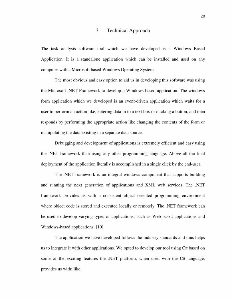
3 Technical Approach
The task analysis software tool which we have developed is a Windows Based
Application. It is a standalone application which can be installed and used on any
computer with a Microsoft based Windows Operating System.
The most obvious and easy option to aid us in developing this software was using
the Microsoft .NET Framework to develop a Windows-based-application. The windows
form application which we developed is an event-driven application which waits for a
user to perform an action like, entering data in to a text box or clicking a button, and then
responds by performing the appropriate action like changing the contents of the form or
manipulating the data existing in a separate data source.
Debugging and development of applications is extremely efficient and easy using
the .NET framework than using any other programming language. Above all the final
deployment of the application literally is accomplished in a single click by the end-user.
The .NET framework is an integral windows component that supports building
and running the next generation of applications and XML web services. The .NET
framework provides us with a consistent object oriented programming environment
where object code is stored and executed locally or remotely. The .NET framework can
be used to develop varying types of applications, such as Web-based applications and
Windows-based applications. [10]
The application we have developed follows the industry standards and thus helps
us to integrate it with other applications. We opted to develop our tool using C# based on
some of the exciting features the .NET platform, when used with the C# language,
provides us with; like:

21
• Garbage Collection: The .NET Framework's garbage collector manages the
allocation and release of memory for your application. Each time you create a
new object, the common language runtime allocates memory for the object from
the managed heap. As long as address space is available in the managed heap, the
runtime continues to allocate space for new objects. However, memory is not
infinite. Eventually the garbage collector must perform a collection in order to
free some memory. The garbage collector's optimizing engine determines the best
time to perform a collection, based upon the allocations being made. When the
garbage collector performs a collection, it checks for objects in the managed heap
that are no longer being used by the application and performs the necessary
operations to reclaim their memory. [11]
• Exception Handling: Exception handling in .NET is a structured form or error
handling that differs from the unstructured error handling such as On Error Goto
of Visual Basic. In structured error handling, any number of different error
filtering conditions can be set in place for a block of code. Structured error
handling allows you to dictate proper programming to those who use your code.
• Type Safety: Type-safe code is code that accesses types only in well-defined,
allowable ways. Given a valid object reference, type-safe code can access
memory at fixed offsets corresponding to actual field members. However, if the
code accesses memory at arbitrary offsets outside the range of memory that
belongs to that object's publicly exposed fields, it is not type-safe. Type safety is
important for assembly isolation and security. When code is type-safe, the
common language runtime can completely isolate assemblies from each other.
22
This isolation ensures that the assemblies cannot adversely affect each other, and
thus increase application reliability.
• Caching: .NET automatically caches classes when they are compiled, so that they
can be delivered extremely fast when they are called. But the Framework also
offers some other cool types of caching, such as output caching, where certain
parts of web pages that are dynamically generated can be stored on the hard drive
in static form, so that they can be delivered directly instead of being generated
every time.
After considering the software tools and technologies we are going to use in developing
our software system, we will now proceed further by explaining the software design
which we choose to use in developing our system, the alternatives available and the
advantages of our choice.
We have already mentioned that we shall be using the MVC architecture pattern
in developing our system. Now we will briefly explain the different flavors of the MVC
architecture patterns available at hand and the one we decided to incorporate is our
system design.
3.1 Variations of the MVC Pattern
There are 3 main variations of the MVC pattern, namely the Passive model, the Active
model and the Observer model. In this section we will briefly describe them.

23
3.1.1 The Passive MVC Model
The passive model is employed when one controller manipulates the model exclusively.
The controller modifies the model and then informs the view that the model has changed
and should be refreshed (see Figure 2). The model in this scenario is completely
independent of the view and the controller, which means that there is no means for the
model to report changes in its state.
The HTTP protocol is an example of this. There is no simple way in the browser
to get asynchronous updates from the server. The browser displays the view and responds
to user input, but it does not detect changes in the data on the server. Only when the user
explicitly requests a refresh is the server interrogated for changes.
Figure 2: Passive MVC Model [12]

24
3.1.2 The Active MVC Model
The active model is used when the model changes state without the controller's
involvement. This can happen when other sources are changing the data and the changes
must be reflected in the views.
Consider a stock-ticker display. You receive stock data from an external source
and want to update the views (for example, a ticker band and an alert window) when the
stock data changes. Because only the model detects changes to its internal state when
they occur, the model must notify the views to refresh the display.
Figure 3: Active MVC Model [13]
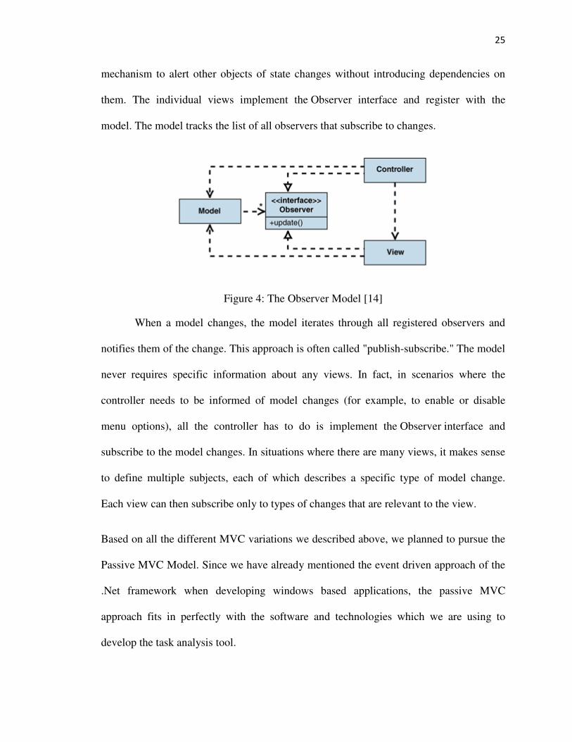
3.1.3 The Observer Model
One of the motivations of using the MVC pattern is to make the model independent from
of the views. If the model had to notify the views of changes, you would reintroduce the
dependency you were looking to avoid. Fortunately, the Observer pattern [9] provides a
25
mechanism to alert other objects of state changes without introducing dependencies on
them. The individual views implement the Observer interface and register with the
model. The model tracks the list of all observers that subscribe to changes.
Figure 4: The Observer Model [14]
When a model changes, the model iterates through all registered observers and
notifies them of the change. This approach is often called "publish-subscribe." The model
never requires specific information about any views. In fact, in scenarios where the
controller needs to be informed of model changes (for example, to enable or disable
menu options), all the controller has to do is implement the Observer interface and
subscribe to the model changes. In situations where there are many views, it makes sense
to define multiple subjects, each of which describes a specific type of model change.
Each view can then subscribe only to types of changes that are relevant to the view.
Based on all the different MVC variations we described above, we planned to pursue the
Passive MVC Model. Since we have already mentioned the event driven approach of the
.Net framework when developing windows based applications, the passive MVC
approach fits in perfectly with the software and technologies which we are using to
develop the task analysis tool.
26
In the Passive MVC approach, the role of the View is simply reduced to that of
container of all controls that exist to provide the visual graphics. Thus the user interface
is split into two parts, the view that handles the display and the controller that responds to
the user actions. The controller does not only handle the response to the user actions, but
also updates the view based on the changes in the model.
Thus our technical design approach is different from the typical MVC approach
since we now have a completely passive view that is no longer responsible for updating
itself from the model. All of the logic is contained in the controller and there is no
dependency in either direction between the view and the model.
The View, in our case is the windows form which is the container of all the
windows controls that aid in creating hierarchical tasks. The event driven programming
approach allows us to code the Controller that responds to the user actions performed on
the Controller and update the Model and/or update the View based on the change in the
model. The actions performed on the View are hard wired with the event handlers in the
Controller. The Controller code resides in code behind C# language files whereas the
View is the designer.
The Model contains all of the application logic and is oblivious of the View and
how the data is reported back to the user. The entire application logic again resides in
separate C# files.
The data generated and used by our software system is also a part of the Model.
We choose to store our data in XML files. We choose to use XML files over using a
traditional relational database or flat files for that matter. The XML has many advantages

27
for the exchange of information between the Model and the View. Some of the benefits
of using XMLs are stated below:
• XML is a platform independent language. XML is fully compatible with various
applications in Java or .NET, and it can be combined with any application which
is capable of processing XML irrespective of the platform it is being used on.
• XML uses human language tags and thus is extremely easy to read and
understand. It also is an extendable language, meaning that we can create our own
tags or use already existing ones.
• XML files are the best way to represent hierarchical or tree structured data. In our
case this is extremely important because of the nature of our task analysis tool
which processes and creates hierarchical tasks.
• Since we decided to use C# as a language with the .NET platform to develop our
application, the C# language has an extremely powerful, easy to use and flexible
XML parser. This makes it extremely easy to manipulate data stored in XML files
for our system.
We agreed to develop our software system using the Passive MVC pattern based on some
of the benefits as listed below:
• Speed and Ease of Testing – We can drastically reduce the testing time of our
software system when using the passive approach since we can isolate the
controller from the view and the model, and use mock objects to test the system
as a whole. This is possible since the view is a dumb entity and does not contain
any code logic.

28
• Incorporate Multiple Views – Since the event handling is separated from the
view, it becomes easier to have the same controller target multiple views. Not
only that but we can use the same controller logic to implement windows forms,
web forms and even windows mobile forms. This would enable us to develop a
windows and a web based version of our software tool using nearly the same
code.
• Varied Models – Since the controller decouples the view and the controller, we
can switch between various types of data stores like flat files, XML files and
Relational Databases.

29
4 Implementation
To succeed in our endeavor, it was imperative that we followed a structured approach in
developing the software product. So we explain the process of implementation of our
thesis by explaining the software development methodology and processes we followed.
A software development methodology refers to the framework that is used to
structure, plan and control the process of developing an information system. There are a
wide variety of frameworks to choose from, each with their own strengths and
weaknesses. Based on the technical expertise and software tools available we decided to
follow the Object Oriented approach. The object oriented programming model uses
“objects” - data structures consisting of data fields and methods together with their
interactions – to design applications and computer programs.
Object oriented approach to system analysis enables very helpful projections of
the system structure to the common sense perception based on communicating objects.
One more level of abstraction has been created - between subsystems with data and
procedures; there are objects which cluster data and functions into structures.
The advantage of this is encapsulation and data hiding. The concept of grouping
objects into object classes enables extended code reuse. Functionality and data of the
entire system is distributed among objects building up the system. Functionality
distribution and partitions improve maintainability, reparability, resolvability and
reusability of software.
Each software development methodology has more or less its own software
development process. We have implemented our software system using one of the most
common software development processes know as the “Waterfall Model”. The Waterfall

30
Model is a sequential software development process, in which progress is seen as flowing
steadily downwards through the phases of Requirement Specification, Design,
Construction, Integration, Testing and Debugging, Installation and Maintenance. But
based on the complexity of the software system, we can skip some of the steps or merge
some activities.
Thus while developing the hierarchical task analysis software tool, the sequential
steps we followed were: Requirement Analysis, Architectural Design, Coding, Testing
and Release. The steps which lay focus on the object oriented methodology are analysis,
design and coding.
Before we actually dive into the details of requirement analysis, it is important to
understand the objective we are trying to achieve while developing this software system.
4.1 Objective
The hierarchical task analysis tool which we have developed will be used in a project to
improve the outcome of injured patients by increasing the efficiency of trauma
resuscitation. This project is expected to identify factors associated with deviations from
Advanced Trauma Life Support (ATLS) which is a standard protocol for trauma
resuscitation, and to develop novel technology for tracking and validating evaluation and
treatment steps during trauma resuscitation. [15]
To develop a theoretical model of trauma teamwork based on activities
observable during trauma resuscitation, it is important to identify and construct the
hierarchical goals. Thus a goal tree is used for the top down methodology to determine
quantitative parameters for the modeling of human activity during trauma resuscitation.
This goal tree starts with the high-level goals of trauma resuscitation and derives sub-

31
goals as well as input parameters needed to achieve them. So, our hierarchical task
analysis tool is used to construct this goal tree.
It is extremely important for this tool to be user friendly, efficient and accurate.
The output of our software tool, will then work as an input to a probabilistic model of the
ATLS compliant team activities to detect any deviation from the protocol itself. This
probabilistic model will be a software program.
4.2 Requirement Analysis
This is an extremely important phase of the software development process with the main
focus oriented towards deep and complete understanding of user needs and expected
functionality of the system. Close cooperation between user and designer is necessary
which very often has the form of a series of recorded sessions.
We performed requirement analysis step and as a result delivered two important
documents: A Use case document and a User Interface design in the form of wireframes
– which is a visual representation of the software user interface with key page elements,
such as headers, footers, navigation content and other controls which hold system data.
The Use case document tables the potential requirements of a new software system. Each
use case provides one or more scenarios that convey how the system should interact with
the end user or another system to achieve a specific business goal. We have created a use
case document using simple language and avoiding technical jargons. The use cases do
not describe the internal working of the system. They simply show the steps that a user
follows to perform a task. Appendix A shows the Use case document for our software

32
system. This document is one of the first steps in the software development process since
it functions as a contract between the client and the software provider.
During the requirement analysis phase, we also performed software prototyping,
which allows people who have stake or interest in the system get an overview of how the
user interface will look like. We created wire frames as our approach to software
prototyping. Wireframes are useful early stage techniques to depict the UI even though
they are non-interactive and usually very broad. Though often simplistic, this style of
prototyping is useful because they can be very quick to create and don’t require too much
technical expertise to put together. In Appendix A, we have shown all the wire frames
which we developed. The wireframes also helped us in reducing the actual development
time since we already had model designs to follow during coding.
4.3 Architectural Design
In the architectural design phase, the software requirements are transformed into
definitions of software components and their interfaces to establish the framework of the
software. We developed the design based on the requirement documents we created
previously. In this phase we built a complete physical model which describes the solution
in concrete, implementation terms. This physical model is used to produce a structured
set of component specifications that are consistent, coherent and complete. Each
specification defines the functions, inputs and outputs of the component.
Usually during the design phase, two separate documents are produced, namely
the Top-Level Design document and a Detailed Design Document. The aim of the top
level design document is to identify the modules that should be in the system, the

33
specifications of these modules, and how they interact with each other and generate the
desired results.
During detailed design the internal logic of each of the modules specified in the
top level design is decided. The algorithms, logic and the data structure are decided. In
our system design phase, we came up with just the high level design. Since our system
does not contain a very large number of components, or a complicated logic and data
structure, it was possible to depict the system using just a high level architecture diagram.
Along with the architecture diagram, we also created a Class Diagram for our system. In
this section, we will describe in detail both the architecture diagram and the class
diagram.
The technical architecture diagram below provides a high level overview of the
goals of the architecture, the use cases supported by the system and the architectural style
and components that have been best selected to achieve the use cases. The architecture
diagram complements the code that we have written to develop the system.
But before we start explaining our architecture diagram; it is important to learn
some terms which are specific to the hierarchical task analysis tool that we have set out to
develop. These terms will be very helpful while interpreting the technical architecture
diagram and the class diagram of our system. These terms with their definitions are
documented in Appendix A.
The Hierarchical Task Analysis Tool uses a Passive MVC architecture approach
and we explain the different layers of the architecture diagram below:

34
View:
The View in our software system is the topmost layer represented in our software
architecture diagram. This is the layer with which the user interacts. The View gives us a
representation of the Model. This layer consists of various Windows Forms which act as
containers of numerous Windows controls like textboxes, buttons, labels, panels and
listboxes.
The View is extremely important to the user, since it is this layer which
determines the ease with which the user can use our software system. Thus, designing
this layer required us to put in considerable thought and iterations before finalizing the
graphical user interface. We used wireframes, which are visual guides that help the
programmer in developing the user interface of any software application that requires
human intervention. These helped provide a structure and flow to the software system.
The Tree Architect user interface consists of the following forms:
Table 1: View Classes
Form Name Description
Main This is the main form where the Processes can be viewed and
edited. It presents the Process to the user in the form of a
TreeView control. It also consists of a Menu that allows the user
to make appropriate selections to load and create new Processes,
edit Processes by adding, editing and ordering Goals and State
Variables, and add and edit Plans in the Process.
LoadProcesses This loads a list of existing Processes. User can select one of

35
these Processes to view, edit or use as a template for creating a
new Process. It is presented as a list in a Listbox control.
ProcessName This is used to give a unique name to the new Process.
AddGoals This screen has controls that are used to add and remove Goals
in a Process or a Process Goal. A new Goal can also be created
using this screen. Available and Selected Goals are shown in 2
respective Listboxes to the user and user can select and unselect
Goals using buttons.
AddStateVariables This screen has controls that are used to add and remove State
Variables to a Goal. A new State Variable can also be created
using this screen. Available and Selected State Variables are
shown in 2 respective Listboxes to the user and user can select
and unselect State Variables using buttons.
PlanDetails This is used to add Plans to Processes and Goals. 3 types of
Plans can be added here and they are Straight Forward Plan,
Freeform Narrative Plan and Plans with Alternatives. These are
presented to the user in the form of a Radio Buttons Group
control.
EnterCondition This is used to add an “If” condition to a set of Order and Range
values in “Plan with Alternatives” type of Plan.

36
AddAlternative This is used to provide the name of the alternative when the user
tries to add a new alternative to the “Plan with Alternatives”
type of plan.
OrderTasks This is used to order Goals and State Variables in a Process.
AddEditDescription This is used to add and edit descriptions to a Process, Goal or a
State Variable.

37
Figure 5: Technical Architecture

38
Controller:
The architecture diagram above depicts the Controller as the layer between the Model
and the View. That is exactly what it does in our software system. It prevents the View to
be tightly coupled to the Model. Each of the forms in the View has a code-behind file
which contains all the code logic regarding handling the user input. These code-behind
files become the Controller in our system.
Whenever a user performs any action in the View or the windows
forms by either clicking a button or typing some text into a textbox, an event takes place
and these events are handled by event handlers, which are a part of the controller code
logic. Thus controller not only interprets the user input, it also manipulates the model
based on the input. By keeping the View and the Model loosely coupled our system
remains flexible and scalable enough to replace the View and Controller with an alternate
View and an alternate Controller. The details of all the controllers shown in the
architecture diagram are given below:
Table 2: Controller Classes
Class Name Description
Main.cs The Main Form allows the user to view and edit the Processes
in Tree architect. All the user actions like loading and
creating new Processes, adding and editing Goals, State
Variables and Plans are captured in Main.cs class and
appropriate forms are displayed to the user. Like when the
user wants to Add or Edit Goals to the Process, he selects

39
Add/Edit Goals option from the Menu and this event is
captured in the Main.cs class. This class responds by
displaying the AddGoals Form to the user with Available and
Selected Goals populated in the respective List boxes.
LoadProcesses.cs This loads the list of existing Processes. The Load event of
this class queries the database (with the help of the Model
which will be explained in the next section) and loads all the
existing Processes in the List Box on the LoadProcesses
Form.
ProcessName.cs This is used to give a unique name to the new Process. The
OK button click triggers the event which checks that the
Process name entered by the user is unique and when this
validation is done, adds the process name to the Process
object.
AddGoals.cs The Load event of this Form is handled to retrieve the
selected Goals of the Process in context and load them in the
Selected Goals List Box. The remaining system Goals are
populated in the Available Goals List Box. The “>>” and
“<<” button events have been handled to move the Goals
from Available Goals List box to Selected Goals list box and
vice versa. The class also handles events to add totally new

40
Goals to the system.
AddStateVariables.cs As explained for AddGoals.cs class above, this class handles
displaying and addition of State Variables to the Process or
system.
PlanDetails.cs As mentioned before, 3 types of Plans can be added here and
they are Straight Forward Plan, Freeform Narrative Plan and
Plans with Alternatives. These are presented to the user as a
Radio buttons group control. The Radio Button’s
CheckedChanged event has been handled to display controls
related to the selected plan.
EnterCondition.cs This is used to add an “If” condition to a set of Order and
Range values in Plan with Alternatives type of plan. Click of
Ok button on this Form adds the condition to the Process
object.
AddAlternatives.cs This is used to add the alternative name in Plan with
Alternatives type of plan. Click of OK button on this form
adds the alternative to the
Alternatives listbox on the Plan Details screen.
OrderTasks.cs On Load event of this form, the selected Goals or State
Variables are populated in the Available Goals / State
Variables Listbox. User inputs for ordering of the tasks are

41
captured when the user clicks on “>>” and “<<” buttons, and
the button clicks are handled to populate the 2 Listboxes as
per user need.
AddEditDescription.cs This is used to add and edit descriptions to a Process, Goal or
a State Variable. OK button click event of this class adds the
description to the appropriate Process, Goal or State Variable
object.
Model:
The Model comprises of the data, state and application logic. The Model in our
architecture diagram contains three separate layers, namely the Business layer, Data
Access Layer and the Information Layer. The details of all these 3 layers are given
below:
Datasource Layer: The Datasource layer stores the data which our system creates,
manipulates, and displays to the user. The list of XML files which are present in the
Datasource layer as follows:
• ProcessList.xml - Contains list of all the Processes created by the user along with
their descriptions.
• GoalsList.xml - Contains list of all the Goals created by the user along with their
descriptions.
• StateVariablesList.xml - Contains list of all the State Variables created by the user
along with their descriptions.

42
• Individual Process details XMLs - these are XMLs of all the Processes listed in
ProcessList.xml. Each xml contains the details of the Process, the Goals and State
variables in the Process and the Plans associated with it.
Data Access Layer: The Data Access layer consists of classes which are used to
manipulate, retrieve and store data in to the various XML files described in the
Datasource layer.
Table 3: Model Classes - Data Access Layer
Class Name Description
AccessProcesses.cs This has methods like UpdateProcess and ListAllProcesses
to interact with the individual Process XMLs and
ProcessList.xml. It is used to add and update Processes to
Tree Architect. It also has the method GetProcessDetails
which is used to populate the Process object with the
Process in context. The Process object is then used to
populate the TreeView.
AccessGoals.cs This has methods to add and edit Goals to Tree Architect.
AccessStateVariables.cs This has methods to add and edit State Variables to Tree
Architect.

43
Business Layer: This layer of the Model has classes which take care of the core business
logic related to Processes and various Plans associated with these Processes. The details
about the classes in this layer are as follows:
Table 4: Model Classes - Business Layer
Class Description
HandleProcessView.cs This has methods that are used to populate the control which
shows the Process details on the Main screen. Currently, it
populates the TreeView control. It can be used to populate a
different control also with slight modifications. We have
incorporated 2 different flavors of TreeView control easily
available on internet, namely AdvancedDataGridView and
VIBlendTreeView, to depict this feature of Tree Architect.
HandlePlans.cs This has methods that are used to manage the Plan panel of
the PlanDetails screen. The Plan panel changes based on the
type of plan selected by the user.
Constants.cs It has various common methods that are used to manage the
whole Process creation feature of Tree Architect. It has
abilities to generate the unique id to differentiate each Process
object, and internal Goals and State Variable objects in the
Process.

44
The class diagram is an essential diagram within the Unified Modeling Language (UML).
The class diagrams are a major building blocks used in the object oriented programming
methodology. They describe the structure of the system by showing the system’s classes,
their attributes, and their relationships between the classes.
The class diagram shown below represents both the main objects and
their interactions in the application and the objects to be programmed. The class diagram
box has been divided into three parts:
• The upper part holds the name of the class
• The middle part contains the attributes of the class
• The bottom part gives the methods or operations the class can take or undertake
Each class member, be it either the attribute or the method of the class has a “-” or a “+”
sign at the beginning of its name. These symbols represent the visibility of the
components of the class. The “+” sign means that it is a public member of the class and
so it can be accessed from within the same namespace and from classes belonging to
other namespaces as well. The “-” sign is meant for private class member, which can only
be accessed inside the same namespace.

45
Figure 6: Tree Architect Class Diagram

46
The solid line connecting the two classes shows a unidirectional
association. At the end of each connection, we show the multiplicity value. In our class
diagram, there also exist Composite Aggregation relationships, which is a special type of
association. In a composite aggregation relationship, the child class’ instance lifecycle is
dependent on the parent class’s instance lifecycle. This relationship is depicted in the
class diagram with a solid diamond at the parent class`s end.
From the diagram we can determine that single instances of the
Process class will always have one or more instances of the Goal class. And single
instances of the Goal class could have zero or more instances of the State Variable class.
At the same time a Goal class could hold zero of more instance of the Goal class as Child
Goals. The Process class and the Goal class instances can also have zero or one instance
of the Plan class.
There also exists a composite aggregation relationship between
instances of the Plan class with instances of the Plan Condition class. Since each plan can
comprise of user defined conditions, a single plan instance can contain zero of more plan
conditions. The plan condition is defined using parameters like order, range and an if-
condition. An instance of the plan condition class would contain at least one or more
instances of the Plan Detail class.
The architecture diagram and the class diagram function as inputs to
the Coding phase of our software development process.

47
4.4 Coding
During this phase, based on all the ideas and design documents we had in hand, we begun
the actual task of coding the software system. The two most critical documents which we
used were the architecture diagram and the class diagram.
In earlier chapters, we had decided on the programming platform and
the software language which we will be using based on several conditions. We coded the
entire system by following a well thought and systematic set of steps. Firstly, we created
the system code template. This template included class definitions along with method
signatures.
In the next step, we designed the actual screens using the wireframes
that we created during the requirement analysis phase. This involved adding various
controls and components to the screens like textboxes, labels, and listboxes and
dropdown menus. During the UI design phase, we also added other aesthetic features we
had described in the wireframes, like colors and background images.
Finally, when the UI design is complete, we turned our attention to
coding the templates we had defined in the first step. Here, we wired up the events raised
by the UI controls with handlers in the Controller, and also added code to the method
signatures we had created in the Model. We spent most of our coding time in this step,
since it involved writing complicated algorithms and data manipulation code. We also
spent time debugging incorrect code logic during this phase.

48
4.5 Testing
Software testing is an activity aimed at evaluating an attribute or capability of a program
or a system and determining that it meets the requirements. The difficulty in testing arises
from the complexity of the software. The purpose of testing can be quality assurance,
verification and validation, or reliability estimation.
While developing our system, we performed testing in two separate
phases. The first phase of testing was Unit Testing. The primary goal of unit testing is to
take the smallest piece of testable software in the application, isolate it from the
remainder of the code, and determine whether it behaves exactly as you expect. Each unit
is tested separately before integrating them into modules to test the interfaces between
modules. Unit testing has proven its value in that a large percentage of defects are
identified during its use. We performed unit testing during the time of developing
individual components of our software system. In case of error, we performed debugging
operations on the code logic and fixed errors. This procedure helped us reduce the logical
errors in the individual models present in the Model, View and the Controller. Unit
testing saves time while fixing defects that arise after integrating all the components,
since error debugging becomes more tiresome in an integrated system.
In the next phase, we performed Integration Testing – which is a
logical extension of unit testing. In its simplest form, two units that have already been
tested are combined into a component and the interface between them is tested. A
component, in this sense, refers to an integrated aggregate of more than one unit. We

49
performed integration testing to identify bugs in the software systems which are
otherwise difficult to detect in standalone components.
To make sure all the functional logic in our software system is
correct; we used the use case description which we created in the requirement analysis
phase. We performed integration testing in multiple cycles using different sets of data and
following separate process flows. At the end of each testing cycle, we fixed the noted
defects and after repeating this procedure, we were able to drastically reduce the bugs in
the system. Software testing is always a trade-off between time, budget and quality. We
stopped testing our system after determining the fact that all our major functionalities
which were a part of the requirements document were working as desired.
4.6 Release
Release is the last step of our software development process. As a part of the software
release, we deploy our software application at a file path location on the local system. We
have used ClickOnce deployment technology from Microsoft to solve the deployment
problem of our software system.
We have configured our software application to be self updating, thus
the ClickOnce application will automatically check for updates from the location it was
installed and will automatically download the updates if they exist. For now, we have
deployed our application from a file share, but we also have the option on hand to deploy
it from a file server or a website. So for multiple users to be able to install our software
system and use it, we can specify the publishing location to be a network share, A Hyper
text Transfer Protocol (HTTP) address or a File Transfer Protocol (FTP) address. We also

50
configured our application as a Full Trust Application, but we have the option for it to be
partial and customizable for the security permissions.

51
5 Results
In this section, we will present the user with the results that we have achieved based on
the functional and non-functional requirements of the system. The functional
requirements of our software have been documented in the requirements document in
Appendix A.
In chapter 2 – Related Work, we listed all the functional requirements
which would be incorporated in our software system. Some of the features we provided
were already a part of the software tools discussed, along with some additional features.
A functional requirement is one that specifies a function that a
system/software or system/software component must be capable of performing. These are
software requirements that define the behavior of the system, that is, the fundamental
process or transformation that software and hardware components of the system perform
on inputs to produce outputs.
5.1 Functional Requirements
We have added snapshots of simulation results in Appendix C which prove pictorially the
functional requirements that have been met while designing our software. The
functionalities that have been successfully implemented and now are a part of our
software are listed below:
• The software tool allows us to add and update Processes. We can also reuse an
already existing Process as a template to create new Processes.

52
• The software tool allows us to add goals, sub-goals and state variables to the process.
It also has the ability to allow the user to provide additional description or comments
to each individual goal or state variable.
• The tool provides us with the ability to logically sequence the goals, sub-goals and
state variables.
• The tool stores the goals and state variables as xml data to increase reusability.
• The software tool allows us to import and export processes in the form of xml data.
• The software tool can be used to add plans to the hierarchical task tree. The three
variations of the plans are namely: Straight forward plan, Freeform narrative plan and
an Advanced plan with alternatives.
5.2 Non-Functional Requirements
A non-functional requirement in system software engineering is a software requirement
that describes not what the software will do, but how the software will do it, for example,
software performance requirements, software external interface requirements, software
design constraints and software quality attributes.
The non-functional requirements are system wide qualities, and these
system wide qualities are closely related to the software architecture we choose. We feel
our system architecture is robust, simple and efficient. Thus our software architecture
incorporates a number of non-functional requirements.

53
Since non-functional requirements are difficult to test, we will
evaluate them subjectively. Below, we list down and explain the non-functional
requirements our software system meets and discuss them in details.
5.2.1 Usability
ISO defines usability as “the extent to which a product can be used by specified users to
achieve goals with effectiveness, efficiency, and satisfaction in a specified context of
use”. Usability is a qualitative attribute that assesses how easy user interfaces are to use.
Our software tool has been designed while keeping in mind the
casual users and by providing intuitive controls and features. Some of the factors that
prove the exceptional usability of our software are: learnability, efficiency, errors and
memorability. Our software is extremely easy to learn based on the process maps we
have created. These process maps work as a user guide and visually depict each step that
can be followed to achieve desired results in timely manner. We have included the
process maps in the Appendix C. We have separate process maps to cover all the
functional requirements, and thus it is extremely easy to remember each step while
creating hierarchical task trees using our software.
To improve the efficiency and error-handling capabilities of the
software, we have provided descriptive pop-up messages when a system error is
generated due to user action. The error messages are in simple language with a brief
solution. Some of the benefits of usability are: Higher revenue through sales, increased
user efficiency and satisfaction, reduced development costs and reduced support costs.

54
5.2.2 Open Source
Open source software is computer software that is available in the source code form. The
distribution rights also play an important role in determining whether the software is
really open source or not. We have decided to release our software tool as open source
software since we see the potential in our software tool to evolve in to a more creative,
faster and portable version. We have decided to allow free distribution and redistribution
of our software. Thus we will provide users with the option to download the source code
in compiled and non-compiled form, while performing the software installation.
Some of the characteristics that turn into advantages of open source
models are the availability of the source code and the right to modify it, the right to
redistribute modifications and improvements to the code, and the right to use the software
in any way one desires.
5.2.3 Scalability
In software engineering, scalability is a desired property of a system, a network, or a
process, which indicates its ability to either handle growing amounts of work in a
graceful manner, or to be readily modified. For example, it can refer to the capability of
the system to increase total throughput under an increased load when resources are added.
A software system can be scalable in many different dimensions; we
believe our software tool is load scalable and is also functionally scalable. Load
scalability is the ability for a distributed system to easily expand and contract its resource
pool to accommodate heavier and lighter loads. Alternatively, the ease with which a

55
system or component can be modified, added or removed to accommodate changing load
also determines whether a software system is scalable or not.
Functional scalability is the ability of a software system to improve
the system by adding new functionality at minimal effort.
5.2.3.1 Load Scalability
Currently we have an xml database, and since the software is a single user tool, the xml
data is stored locally on the user’s computer. Hence in this case we have a sizeable
constraint on the size of data store we have available.
But we can change the location of the data store to a centrally located
file server with a very large memory capacity. This would just require us to have a LAN
connection, and a minimal change in the code. Thus this will provide us with a large and
improved data storage capability. It will also de-centralize our software system, making it
possible to access data from various work stations. Thus this discussion proves that our
software system has been designed to be load scalable.
Thus by adding some extra hardware resource, we can improve the
throughput of our software system. The example which we have provided is an example
of horizontal scaling or scaling-out. Horizontal scaling means adding more than one node
to the already existing software system. This scale-out mode is frequently used to satiate
the increased demand for shared data storage.

56
5.2.3.2 Functional Scalability
Our software tool is also scalable from the functional perspective. We have designed the
software based on the MVC architecture pattern, which basically provides us with an
extremely scalable software model.
In the previous section, we showed how we can increase the
throughput of our system. We showed how it is possible to have a separate file server to
store the xml files. Instead of storing xml files on the file server, we can also use a
relational database which stores our hierarchical task data in tables.
Basically what we can achieve is, instead of having to store xml files
all by themselves, we can store them in a relational database system like Microsoft SQL
server or in a MySQL database. This would not require a great deal of change in the code
since our MVC architecture allows us to plug in a different Model without changing the
View, since they are isolated from each other.
Storing our xml files in a relational database table will provide us
with additional features like faster data access and secure data storage. And as mentioned,
the coding effort and required time to implement this feature will not be painstaking
because of our highly scalable system architecture.
5.2.4 Extensibility
Extensibility is a systematic measure of the ability to extend a system and the level of
effort required to implement the extension. Extensions could be through the addition of
new functionality or through modification of existing functionality. A good architecture

57
provides the design principles to ensure that a software system is extensible. Our MVC
architecture pattern just does that.
As we have already explained in the previous chapters our MVC
architecture pattern separates the User interface design and the application logic. The user
interface design or the presentation logic resides in the View, which is the topmost layer,
whereas the application and data logic reside in the Model. The View and the Model are
loosely coupled and thus can be replaced with another View or a different type of Model.
To show that our software system is extensible, we have
implemented three different types of views. These are just different techniques which can
be used to represent hierarchical task data. We have been able to achieve this with
minimal code logic change. All the three views use the same model and can be generated
dynamically on run time. This, undoubtedly, is the biggest advantage our software system
has over the others which are available in the market.
Thus, we have not only provided open source software, but to
complement it, we have developed an architecture model which is extensible to allow
other developer communities to improve and modify the software system based on their
specific requirements, and redistribute them.
Below, we show the different flavor of views that we have
implemented besides the basic tree control which we developed originally. We generated
all the views using the same xml data available at runtime.

58
View 1 - Basic Tree Control (Currently used in the system)
Figure 7: Basic Tree Control (Currently used in the system)

59
View 2 - New View
Figure 8: New View
View 3 - VIBlend tree view
Figure 9: VIBlend tree view

60
6. Conclusion
In this thesis we had set out to design and develop a simple, robust and flexible
hierarchical task analysis software tool. We studied various tools available commercially
and non-commercially and were able to implement a list of additional functionalities
which were not available in the existing product like a few mentioned below:
• Provide a number of reusable templates to create task analysis flow diagrams,
including the provision to add more templates.
• Ability to store newly added tasks, sub-tasks or state variables. This saves
tremendous amount of development time for the task analyst, since these can be
used as components to build a new hierarchical task.
• Ability to import and export XML documents, which is a W3C Standard. It is
widely regarded as the future of the internet, since it is a standard which can
seamlessly integrate with any system.
• Ability to connect our system with a data store like the Microsoft SQL Server
which would boast the storage capabilities of the tool and can be used to integrate
with other systems in a professional development environment.
We chose the best available architecture pattern to solve our design problem and were
able to incorporate a number of additional non-functional requirements like usability,
open source, scalability and extensibility.

61
These additional features and qualities make our HTA software tool a viable option to
carry out hierarchical task analysis.

62
7. Future Work
The MVC design pattern promotes the idea of extending the software to provide
additional features to the software. Because of time constraints we have not been able to
add many aesthetic features to our software.
The tool can be improved to include some styles and color coding schemes to
make it look more intuitive to the user. At the same time more sophisticated controls can
be added to simplify the procedure of creating tasks, adding goals and sub-goals.
This would not require the application logic to change. We would only have to
modify the classes in the controller and the windows forms.
Another possible upgrade possible would be to converting the entire windows
based application to a web based version. This would make it a multi user application and
eliminate the installation step all together.

63
Appendix A
Requirement Analysis Document
Table 5: Functional Requirements
Id High Level
Requirements
Requirement Description
1
Viewing /
Editing a
Process
As an administrator, I should be able to retrieve all the
existing Processes of the system.
2
As an administrator, I should be able to view and edit any of
the Processes after they have been listed.
3
Creating a new
Process
As an administrator, I should be able to use the existing
system Processes as templates to create new Processes.
4
As an administrator, I should be able to add a new Process to
the system without using a template.
5
The system must ensure that the new Processes created have a
unique name.
6
As an administrator, I should be able to provide a description
to the Process.
7
Managing
Goals
As an administrator, I should be able to add already existing
System Goals to a Process.
8
As an administrator, I should be able to add new Goals to the
current Process in case the already existing list of Goals does
not fulfill the business.
9
As an administrator, I should be able to add sub Goals to the
Process Goals.
10
As an administrator, I should be able to remove Goals from a
Process or from the Process Goals.
11
As an administrator, I should be able to provide a description
to a Goal.
12
Managing State
Variables
As an administrator, I should be able to add already existing
System State Variables to a Process Goal.
13
As an administrator, I should be able to add new State
variables to the current Process Goal in case the already
existing list of Goals does not fulfill the business.
14
As a system, I should ensure that the State Variables are only
added at the Process Goal level and not at the Process level or
a State variable level.
15
As an administrator, I should be able to remove State
Variables from a Process Goal.
16
As an administrator, I should be able to provide a description
to a State Variable.
17 Logical As an administrator, I should be able to order the Goals in the

64
Ordering of
tasks
Process or in the Process Goals in a logical flow.
18
As an administrator, I should be able to order the State
Variables in the Process Goals in a logical flow.
19
As an administrator, I should be able to reset the order of the
Goals or State Variables.
20 Managing Plans
As an administrator, I should be able to add one of the
following plans to the Process or the Goals of the Process:
1. Straight Forward Plan.
2. Freeform Verbal Plan.
3. Plan with Alternatives.
21
As a system, I should ensure that the Plan is not added to a
Process with no Goals.
22
As a system, I should ensure that the Plan is not added to a
Process Goal with no sub Goals or State Variables associated
with it.
23
As an administrator, I should be able to provide Order and
Range rules when I select Straight Forward Plan as the Type
of Plan.
24
As a system, I should provide the following values as the
Order options to the administrator:
1. Do all in sequence
2. Do all in any order
3. Do any one
4. Optionally do any
5. Do concurrently
6. Do not do
25
As a system, I should be able to dynamically populate the
Range dropdown with the appropriate values based on the
number of sub tasks present in the Process or Process Goal to
which the Plan is being added. For ex, if the Plan is being
added to a Goal which had 4 sub Goals, the System should be
able to populate the Range dropdown with the following
values:
> 1 only
> 1 - 2
> 1 - 3
> 1 - 4
26
As a system I should be able to dynamically populate another
row of Order and Range dropdowns based on the Range
selection made by the administrator. For ex. If the
administrator selects the Range value as "1 - 2" in the example
given above in requirement no. 25, the System should
populate a new row of Order and range dropdowns, with the
Range dropdown values dynamically set to
> 3 only

65
> 3 - 4
in case the administrator selects the last value of the Range
dropdown, like "1 - 4" in case of example in the requirement
no. 25, the System should not add a new row of order and
Range dropdowns.
27
As an administrator, I should be able to provide a freeform
text when I select Freeform Verbal Plan as the Type of Plan.
28
As an administrator, I should be able to provide Order and
Range rules when I select Plan with Alternatives as the Type
of Plan.
29
As a System, I should follow same instructions to manage
Order and Range dropdowns as mentioned in requirement " ".
30
As an administrator, I should be able to add an "If" condition
with each pair of Order and Range values indicating that these
instructions should be following only when the mentioned "If"
condition is fulfilled.
31
As an administrator, I should be able add alternatives in the
"Plan with Alternatives" with each alternative having its own
set of If condition, Order and Range rules.
32
As a System, I should be able to dynamically generate the
Plan statement as the administrator makes selections in the
Order and Range dropdowns in case of Straight Forward Plan
and Plan with Alternatives.
33
As a System, I should be able to dynamically set the plan
statement to the freeform verbal text written by the user in
case of the Freeform Verbal Plan.
34
As a System, I should be able to add the generated Plan
Statement to the concerned Process or the Process Goal and
display it to the administrator when he saves his Plan.

66
Wireframes:
Screen Name: Main
Description: This is the first screen presented to the administrator when he starts the
TreeArchitect. The details of the menu items in the screen are explained below.

67
Screen Name: List Processes
Description: When the administrator selects “Open / Edit” option from the File Menu on
the Main screen, he will be presented with this screen with all the existing Processes
populated in the list box.
When the administrator selects “New using Template” option from the File Menu on the
Main screen, he will be again presented with this screen so that he can choose one of the
existing Processes as template to create a new Process.

68
Screen Name: Main (with Process Details populated)
Description: When the administrator selects a Process from the List Process screen, he is
presented with the Process Details screen with the details of the selected Process
populated.
When the administrator selects “New” option from the File Menu on Main screen, he will
be presented with Process Details screen with all the fields empty.

69
Screen Name: Add Goals
Description: This screen is presented to the administrator when he selects the Process or
a Goal on the Main Screen and then selects the Add Goal option from the Add menu on
Main screen. Multiple goals can be added to a parent goal or to the process.

70
Screen Name: Add State Variables
Description: This screen is presented to the administrator when he selects a goal and then
selects the Add State Variable option from the Add menu on Main screen. Multiple state
variables can be added to a parent goal.

71
Screen Name: Order Tasks
Description: This screen allows the user to add/edit the logical ordering of Goals/ State
Variables that exist as sub-tasks to an already existing Process or Goal.
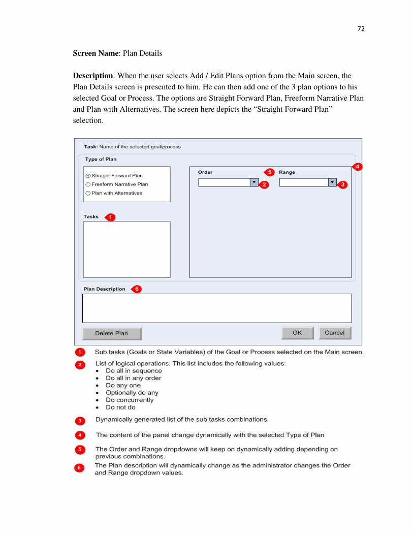
72
Screen Name: Plan Details
Description: When the user selects Add / Edit Plans option from the Main screen, the
Plan Details screen is presented to him. He can then add one of the 3 plan options to his
selected Goal or Process. The options are Straight Forward Plan, Freeform Narrative Plan
and Plan with Alternatives. The screen here depicts the “Straight Forward Plan”
selection.

73
Screen Name: Plan Details
Description: When the user selects Add / Edit Plans option from the Main screen, the
Plan Details screen is presented to him. He can then add one of the 3 plan options to his
selected Goal or Process. The options are Straight Forward Plan, Freeform Narrative Plan
and Plan with Alternatives. The screen here depicts the “Freeform Narrative Plan”
selection.

74
Screen Name: Plan Details
Description: When the user selects Add / Edit Plans option from the Main screen, the
Plan Details screen is presented to him. He can then add one of the 3 plan options to his
selected Goal or Process. The options are Straight Forward Plan, Freeform Narrative Plan
and Plan with Alternatives. The screen here depicts the “Plan with Alternatives”
selection.

75
Screen Name: Enter Condition
Description: When the user clicks on the “If” button on the Plan Details screen with
“Plan with Alternatives” selection, he is presented with this screen. He can associate an
“If” condition here for a combination of Order and range values.
Screen Name: Add Alternative
Description: When the user clicks on the “Add” button of the Alternatives section on the
Plan Details screen with “Plan with Alternatives” selection, he is presented with this
screen. He then adds the name of the Alternative before proceeding to add Order and
Range combinations to this Alternative.

76
Appendix B
Task: A task is regarded as a problem to be solved or a challenge to be met. A task can
be regarded as a set of things including a system’s goal to be met, a set of resources to be
used, and a set of constraints to be observed in using resources.
Task Analysis: Task analysis is treated as the process of obtaining information about a
task in order to generate hypothesis concerning sources of inadequate performance or
about designs that will make things better.
Hierarchical Task Analysis: Hierarchical task analysis is a common form of task
analysis which is read bottom-up. Hierarchical task analysis consists of various levels of
tasks. Each level represents a learning level and the top level is the most complex.
Process: The process is the system`s goal. The process is a statement of what the system
is required to achieve.
Goal: The word goal is used to signify a target. In the case of our system, a goal is an
intermediate step to achieve the system wide goal, which is described as the process. In
our system, the word goal can be used inter changeably with the term task.
Sub-goal: A goal is further disintegrated into subsequent sub-goals. These sub-goals act
as intermediate steps in achieving the larger goal, of which they are child nodes. The
central strategy of our hierarchical task analysis software tool is to re-describe goals in
term of sub-goals. In our system, the word sub-goal can be used inter changeably with the
term sub-task.

77
State Variables: State variables form the leaves or the lowest level of the hierarchical
task tree structure. They usually signify the varying parameters or measurable parameters
of the task system. Goals can also form the leaves of the hierarchical task tree but they
are not varying entities.
Plans: Plans describe the order in which the sub-tasks are performed, and the conditions
that trigger their performance. Plans can be specified for any goal that has child goals,
sub-goals or state variables. Plans can be as simple as sequencing of the sub-goals, or
more advanced involving multiple plans that are initiated depending on the conditions (if
else statements) that the user defines.

78
Appendix C
Tree Architect Application Screenshots
Main Screen with a Process (without any plans)

79
Add Goals Screen

80
Straight Forward Plan

81
Freeform Narrative Plan

82
Plan with Alternatives 1

83
Plan with Alternatives 1
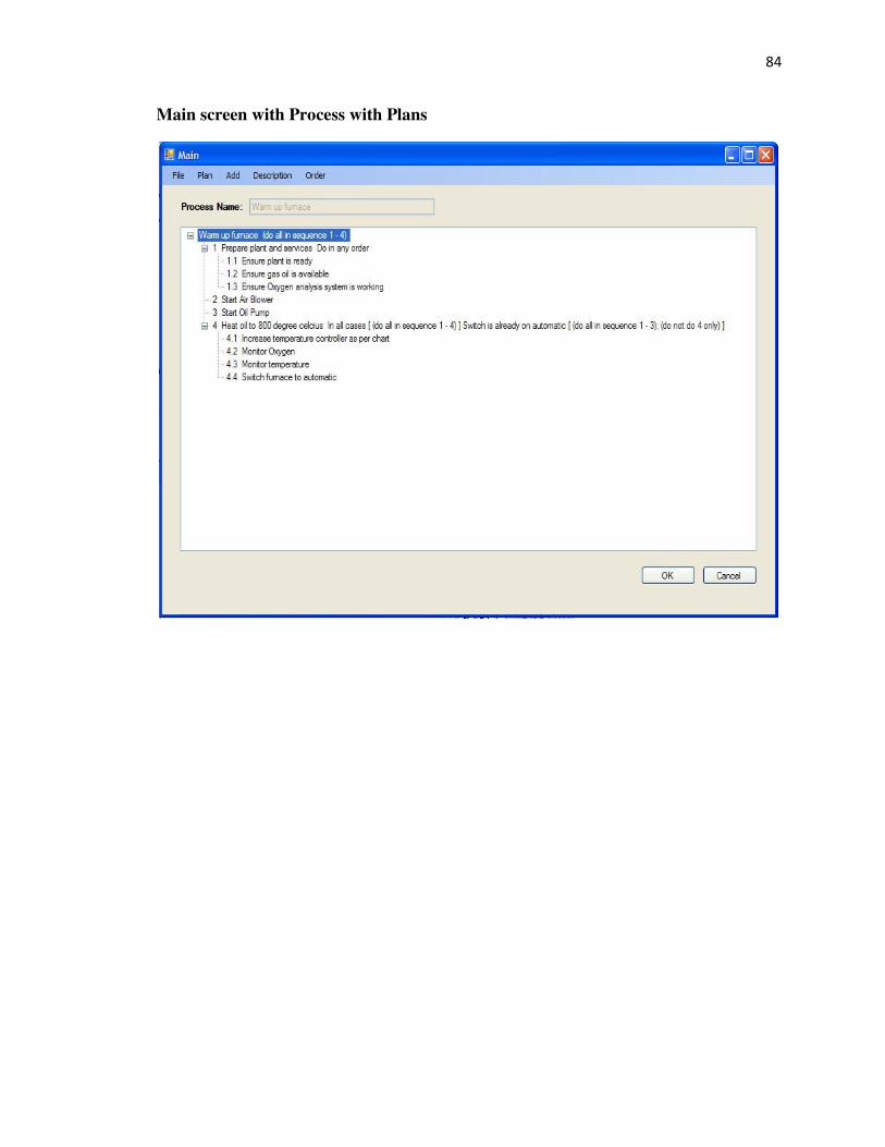
84
Main screen with Process with Plans

85

86

87

88
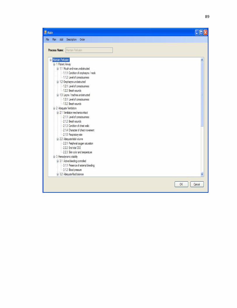
89

90

91
Process Maps
Adding a New process

92
Creating a new process using template

93
Managing Goals

94
Managing State Variables

95
Order Tasks

96
Adding Plans
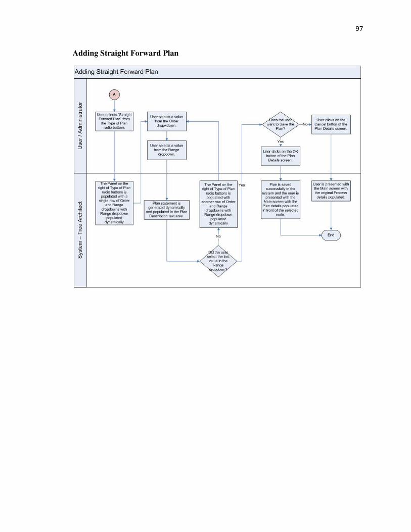
97
Adding Straight Forward Plan
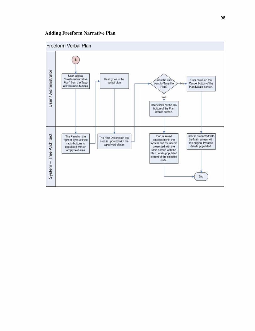
98
Adding Freeform Narrative Plan

99
Adding Plan with Alternatives

100
References
[1] Andy Farmilo, Ian Whitworth, Geoff Hone, Using THE HTA TOOL for Agile
Mission Planning, Department of Information Systems, Cranfield University at the
Defence Academy of the United Kingdom.
[2] Iain S MacLeod, Dr Geoff Hone, Steve Smith, Capturing Cognitive Task Activities
for Decision Making and Analysis, Department of Information Systems
Cranfield University, Defence Academy Campus.
[3] VIP Quality Software. http://www.taskmanagementsoft.com/products/taskmanager/
[4] TaskAnyone. http://www.taskanyone.com/contact.html
[5] Task Architect, Inc. http://www.taskarchitect.com/products.html
[6] Buschmann, F., Meunier, R., Rohnert, H., Sommerlad, P. and Stal, M. (1996).
Pattern-Oriented Software Architecture. John Wiley and Sons. ISBN 0-471-95869-7.
[7] Hussey, A. and Carrington, D., 1997, Comparing the MVC and PAC architectures: a
formal perspective. IEEE Proceedings – Software Engineering, Vol. 144, No. 4, August
1997. 224-236.
[8] Eric Freeman, Elisabeth Freeman, Kathy Sierra, Bert Bates, Head First Design
Patterns, O’Reilly Publications, 2004.
[9] Burbeck, S.1986, Applications Programming in Smalltalk-80(TM): How to use
Model-View-Controller (MVC).
[10] .NET Framework Conceptual Overview.
http://msdn.microsoft.com/library/zw4w595w.aspx
[11] Garbage Collection. http://msdn.microsoft.com/en-us/library/0xy59wtx.aspx
[12] [13] [14] Model View Controller. http://msdn.microsoft.com/en-
us/library/ff649643.aspx
[15] ATLS Program. http://www.facs.org/trauma/atls/about.html