Embed Size (px)
Citation preview

INSTRUCTION MANUAL
MSP – 4 MOTOR PROTECTION


INSTRUCTION MANUAL
MSP-4
MOTOR PROTECTION SYSTEM
Copyright © 2009, Alectryon
ALL RIGHTS RESERVED

TABLE OF CONTENTS
Page
1.0 General Information 2 1.1 Introduction 1.2 Hardware 1.2.1 The MSP-4 Motor Protection Unit 1.2.2 The MSP Monitor 1.3 Power Supply 1.3.1 Power Packs 1.4 Information
2.0 Protection Functions 8 2.1 Thermal Overload 2.1.1 The Thermal Model 2.1.2 Thermistor Input 2.2 One-Start Thermal Capacity Protection 2.3 Stall (Mechanical Jam) Protection 2.4 Phase Loss Protection (Single Phase Detection) 2.5 Phase Reversal Protection 2.6 Ground Fault Protection 2.7 Contactor Protection (Trip Inhibit) 2.8 Short Circuit Protection
3.0 Aux. Protection Functions 12 3.1 Reduced Voltage Starting Control 3.2 Overcurrent Detection 3.3 Undercurrent Detection 3.4 Auto Reset
4.0 Information 13 4.1 The MSP Monitor 4.2 4-20 mA Output

TABLE OF CONTENTS
Page 5.0 Installation 15 5.1 The MSP-4 5.2 The MSP Monitor 5.3 Settings 5.4 Settings for MSP-4-AIP & MSP-4-BIP
6.0 Operation 22 6.1 The MSP Monitor LCD Display 6.2 The MSP Monitor Pushbuttons 6.3 The MSP-4 6.4 The Trip Signal
7.0 Technical Specifications 25 7.1 Current Ranges 7.2 Specifications 7.3 Unit Dimensions
8.0 Options 28 8.1 Low Frequency (LF) 8.2 External Core Balance CT (Models A and B only) 8.3 Power Packs 8.4 Logic Relay Units
9.0 Typical Applications 30 10.0 Typical System Configuration 31 11.0 Location of Internal Components 36 12.0 Quick start, 14 Easy Steps to a Safe Start 37


MSP-4 Motor Protection Unit
MSP Monitor
1

1.0 General Information
1.1 Introduction This manual describes the features of the MSP-4 Motor Protection Unit. The MSP-4 is designed to protect electrical motors and connected loads accurately and user friendly against damages caused by: - thermal overload and cooling problems - mechanical overload - electrical fault conditions It also gives many extra features for total systems protection related to the motor be-ing monitored. Built-in capacitors are able to power the MSP-4 up to 8 hours after the motor is switched off.
The MSP-4 Motor Protection Unit system consists of: (See Section 10): (a) The MSP-4 with all protection functions, built-in current transformers and output
relays. (b) A Power Pack unit for the supply current. (c) The MSP Monitor Unit with a large 6-digit LCD display for actual motor data,
settings and in case of a trip, the cause of the trip. (d) Optional a Logic Relay Unit for extra Relay outputs. The displayed information and alarm signals from undercurrent or overcurrent auxil-iary protection functions enable preventative action to be taken in case an abnormal running situation occurs. The design of the housing and integration of multiple protection functions in a single MSP-4 enables easy and compact installation. User friendly presentation of information about the running condition of the motor and drive system enable a quick response to abnormal situations by appropriate per-sonnel. In case a trip condition does occur, the fault indication identifies the fault thus assuring an optimum repair time and a minimum loss of production. A summary of the MSP-4 protection and alarm functions are as follows.
2

Thermal Protection (a) With a thermal model allowing the user to select one of 490 Motor Time/Current
curves from locked rotor times of 1 sec up to 50 seconds in 0.1 sec steps. To achieve optimum simulation of motor temperature, the cooling characteristics of the model are matched to the thermal capacity setting of the motor. (See Sec-tion 2.1)
(b) Thermistor sensors to detect high temperature problems (i.e. bad cooling etc.).
When a hot resistance is detected a trip will be activated and the motor's re-serve thermal capacity calculated in the thermal model will be forced to approxi-mately minus 20%
Auto Reset (See Section 3.4)
Motor Start Inhibit If the motor's actual reserve thermal capacity is below the ca-pacity needed for one start. (See Section 2.2)
Phase Loss (Single Phase) Protection (See Section 2.4)
Phase Reversal Protection (See Section 2.5)
Ground Fault Protection with built-in or external core balance. (See Section 2.6)
Stall (Mechanical Jam) use as 'shearpin' or jam-during-run. (See Section 2.3)
Auxiliary Protection can be selected by DIP switches. (See Section 3.0) (a) Adjustable current-controlled transition for reduced voltage starting with back-
up time transfer if the motor current fails to reach the set current level is avail-able.
(b) Adjustable underload detection for loss of fluid on pumps, mechanical break-
age, etc. (c) An adjustable overload threshold as a prewarning or as an input signal for ex-
ternal control circuitry.
Contactor Protection when selected, will inhibit a trip if the motor current is greater than the contactor's interrupting capacity. This assures co-ordination between con-tactor and fuses or breaker. (See section 2.7)
Short Circuit Protection (See Section 2.8)
4-20 mA Output Signal related to motor current for remote monitoring or as an in-put signal for a closed loop load controller, PLC etc. (See Section 4.2)
3

1.2 Hardware
1.2.1 The MSP-4 The MSP-4 with all protection functions is designed for DIN rail or rear screw mount-ing. Connecting the MSP-4 to the motor is very easy. On models C, D and MSP-T500 (together with MSP-4-AT500-EP) simply thread the cables through the built-in CT's. On models AIP (External 1A CT’s) the secondary wires are connected to the stud mountings. On models BIP (External 5A CT’s) the secondary wires are simply thread through the built-in CT's. Three built-in current transformers assure a non-saturable measurement of the motor current for the protection functions. The compact dimensions of the MSP-4 and the built-in current transformers and core balance allow for minimum cabinet dimensions thus saving installation costs and enclosure size. On the front of the MSP-4 the following features ensure easy operation: (a) Multi-turn potentiometers to accurately calibrate the settings of the protection
functions to the motor and load characteristics. The settings are very precise and can be read from the MSP Monitor.
(b) A standard DB-25 outlet to connect the MSP Monitor (c) Screw terminals for the Trip Relay (R1) and Auxiliary Protection Relay (R2). (d) Plug-in terminals to connect to thermistors, 4-20 mA output, remote reset, Power Pack and external ground fault. (e) Reset pushbutton to reset the MSP-4 in case a trip condition occurred. Removing the front plate gives access to two 16-position rotary switches and various DIP switches to select the internal settings. (See Section 5)
4

1.2.2 The MSP Monitor The MSP Monitor has a large 6-digit, easy to read LCD display and can be door mounted. The display shows actual running load current, reserve thermal capacity, all settings and fault conditions. The unit can also be used as a portable hand-held monitor which can be plugged into the MSP-4 to analyze running conditions or to define the cause of a trip. On the front of the MSP Monitor the following features are available. (See Section 10.0) (a) A large 6-digit LCD display to show:
• motor status; stop, start or running condition • actual motor load in amperes or percentage of FLA • continuous tracking of thermal capacity as a percentage of full capacity • all settings in the MSP-4 • in case of a trip, the fault condition • the actual motor load being above or below the auxiliary protection function setting (overcurrent/undercurrent protection) (b) READ/SET pushbutton displays any setting or actual motor load or reserve
thermal capacity. (c) FAULT pushbutton displays the cause of a trip. (d) RESET pushbutton resets the MSP-4 after a trip. The reset pushbutton can be de-activated by disconnecting pin 1 in the plug to
the MSP-4. The MSP Monitor has a 1.5 meter cable with a standard DB-25 connector to plug the unit in the MSP-4. At the rear of the monitor, a Relay-Test pushbutton can be used to test the trip relay (R1) and the Auxiliary Protection Relay (R2).
5

1.3 Power Supply The MSP-4 requires a Power Pack. Built-in capacitors energize the electronics up to 8 hours after power down.
1.3.1 Power Packs A Power Pack must be connected to the MSP-4 for the following features: Other Power Packs enable the user to: - Test the ground fault protection circuit (using either external or internal core balance CT). - Utilize the 4-20 mA output signal (See Section 8.2 for details).
6

1.4 Information The MSP-4 not only trips the motor when a fault condition occurs, but it provides in-formation about the actual running condition. This information can be obtained as follows: (a) The LCD display of the MSP Monitor can be used to read the actual motor cur-
rent in amperes or a percentage of rated FLA. Reading an abnormal load condi-tion can mean preventative maintenance is necessary or something abnormal is happening in the drive system.
(b) By activating the READ/SET pushbutton on the MSP Monitor, the motor's re-
serve thermal capacity can be displayed. In case the motor is switched off, this value relates to the possibility of a successful restart.
(c) R2 relay generates an alarm signal when the auxiliary protection threshold is
passed (delay can be adjusted from 0.7 to 6 sec). These signals can be used to take necessary action to avoid damage or loss of quality of the material in proc-ess.
7

2.0 Protection Functions
2.1 Thermal Overload The MSP-4 offers two methods of motor overtemperature protection. The main ther-mal protection uses a thermal model to calculate the reserve thermal capacity of the motor on the basis of motor current related to the rated FLA and the thermal with-stand curve. The second method, working in parallel, is a direct measurement with thermistors. This method is relatively slow, and is only accurate at slower temperature rises. The main reason to add thermistor protection is to detect a temperature rise caused by cooling problems. It also acts as an 'ultimate trip' device to prevent motor destruction from high operating temperatures.
2.1.1 The Thermal Model The thermal model of the MSP-4 follows a basic motor time/current characteristic and is adjustable at 6 x FLA in 0.1 sec steps from 1 sec to 50 sec safe locked rotor time. Up to 490 time/current withstand curves can be generated. This enables the MSP-4 to be closely matched to any motor being protected. A precise tailor made curve that goes far beyond traditional thermal overload protection. Built-in is an automatic transfer to a hot motor curve characteristic set at 80% of the cold curve setting. The transfer from cold to hot is automatic. Cooling is preset on the unit and fixed at 3 minutes for every 1 second of set locked rotor time at 6 x FLA, (i.e. if 10 seconds was set for Locked Rotor Time, a cooling time of 30 minutes will elapse from 0% to 100% reserve thermal capacity). The cal-culated heat development is presented as a percentage of reserve thermal capacity. 100% thermal capacity = cold motor (40°C) 80% thermal capacity = normal running condition 0% thermal capacity = limit temperature (trip) In an overload condition, the time to trip depends on the level of overload, actual mo-tor reserve thermal capacity and rated locked rotor time. The reserve thermal capacity used during a start can be determined by reading the thermal capacity at the beginning and end of the start cycle from the MSP Monitor. This value can then be used to decide how much thermal capacity must be available before a motor can be started without nuisance tripping because of motor overtem-perature (0% thermal capacity)).
8

This reset feature enables an optimum restart time after a trip occurred. The start in-hibit condition is cleared as soon as enough reserve thermal capacity is available to enable a restart of the motor. (See Section 2.2)
MSP-4 TRIP CURVE #90 FOR MOTORS RATED 10 SEC. SAFE LRT
MULTIPLES OF FULL LOAD CURRENT
THE THERMAL MODEL
9

2.1.2 Thermistor Input Thermistors with a low value at low temperature and a high value at maximum al-lowed temperature can be mounted in the motor windings. Use Positive Temperature Coefficient (PTC) thermistors The resistance of a thermistor changes in value within a narrow temperature range (10°-15°C) and cannot be used to read the motor temperature. A thermistor can be considered as a switching element which operates in a certain temperature band. The thermistor input detects a hot resistance above 3300 ohm and the cooling reset is at 2200 ohm. This allows 6 thermistor PTC sensors in series. The trip delay time is fixed at 200ms. If a high thermistor resistance causes a trip signal the reserve thermal capacity of the thermal model is forced to minus 20%, thus synchronizing the thermal model with the thermistor detector and forcing a cooling of the thermal model to an accept-able level before a reset can take place.
2.2 One-Start Thermal Capacity Protection This function inhibits a motor start whenever the actual reserve thermal capacity of the thermal model is too low to allow for a new start. One start of the motor provides the thermal capacity information needed for this function. This information can be adjusted as a percentage of full thermal capacity when setting the 'Reset Level' on the MSP-4. Whenever the actual reserve thermal capacity is below this setting, an automatic inhibit to start the motor at shut down is activated by trip Relay 1 (R1). This function prevents a trip during start and is ideal in conjunction with Logic Relay Unit (See Section 8.3)
2.3 Stall (Mechanical Jam) Protection In an attempt to create an artificial service factor, or to allow for frequent starting cy-cles, motors are often overrated compared with the mechanical load they are driving. In the event of a stall condition developing or a mechanical jam occurring, it is nec-essary to trip out as soon as possible. This prevents taking the motor to its full ther-mal limit or causing mechanical damage to gear boxes or other equipment. The stall protection is inhibited when the motor is starting (i.e. direct-online or re-duced voltage), but on wound rotor motors (it is very dangerous to have high cur-rents on the starter because it causes rotor damage) and soft starters (which do not see a start current), the stall is automatically active after 100 milliseconds.
10

The stall/shearpin protection has a time delay adjustable from 60 ms to 2 sec (in 1 ms steps). If the motor current increases above the stall threshold for the stall time period, Trip Relay 1 (R1) will operate. Stall protection can be disabled or a longer time delay can be provided as a factory modification.
2.4 Phase Loss Protection (Single Phase Detection) A loss of any one of the three phases for 2 seconds activates the trip relay (R1). This function can be inhibited by an internal DIP switch.
2.5 Phase Reversal Protection A reversal of two phases causes the motor to change its rotating direction. In many applications this will damage the driven unit or cause loss of production. The MSP-4 will detect a phase reversal and activate trip Relay 1 (R1). Trip time is fixed at 200msec. This function can be inhibited by setting an internal DIP switch.
2.6 Ground Fault Protection On models C,D & BIP, ground fault protection is provided via built-in core balance. The ground fault threshold is adjustable from 0.5 a to 7.5 A (in .5 A steps). Ground fault protection can be inhibited by setting an internal DIP switch. (See Section 5.1 C) Trip time is fixed at 500msec. It can be changed to 2 sec. as a factory modification. The internal core balance is provided with a test winding which can be connected to a special power pack with ground fault test button (see section 8.2) When interposing current transformers are used (models A & B) to connect the MSP-4 to the motor current (i.e. HV motors), the external core balance version must be selected.
2.7 Contactor Protection (trip inhibit) Motor contactors are not designed to interrupt high fault level currents. To prevent contactor damage when the current is above the contactor's maximum rated level, the MSP-4 will inhibit a trip until the fuses or breaker clears the high current. When the current drops to zero, the trip relay activates. At all times the trip indication is latched. The trip inhibit level is adjustable from 2 to 9.5 x FLA. (See Section 12.0) An optional unit for upstream tripping of breakers (while the contactor inhibit is active is available (Logic Relay Unit). It is also possible to automatically re-close upstream devices using the Logic Relay Unit.
11

2.8 Short Circuit Protection The short circuit threshold is fixed at 10 x FLA with a response time of better than 60 ms. The short circuit protection will activate Relay 1 (R1). Short circuit protection can be disabled or longer response times can be supplied as factory modifications.
3.0 Auxiliary Protection Functions One of the following built-in protection functions can be activated via DIP switches. The auxiliary protection function will activate Relay 2 (R2) and can optimize control and/or warning functions with minimum cost.
3.1 Current Controlled Transition for Reduced Voltage Starting With fixed-time transfer, where load characteristics or line voltage can vary from start to start, high current surges or mechanical torque peaks can be encountered. With a current level being detected by the MSP-4, it is possible to transfer from 'start' to 'run' at an optimum preset motor current rather than time, assuring a smooth electri-cal an mechanical transition. The transfer level is set as a percentage of rated motor FLA with a range of 30%-200%. A built-in time transfer as back-up protection is fixed at 5 x Locked Rotor Ca-pacity setting, i.e., if the Locked Rotor Capacity setting is 10 sec, and the current has not reached the set level in 50 sec (5 x 10 sec), the transfer will take place automati-cally as a time transfer. This override can be inhibited to allow for very long start-up times. (See Section 5.3.6)
3.2 Overcurrent Detection The overcurrent detection signal can indicate the development of an overcurrent be-fore an actual trip occurs. It can also be used to control the motor load or to add ex-tra motors to a drive system (i.e., a pump in parallel in peak demand periods). The overload threshold level is adjustable from 30% to 150% of rated FLA and the signal (R2) will have an adjustable delay period (0.7 - 6 sec) after the motor load crosses the alarm level. When the current returns to a level below this threshold. Re-lay 2 (R2) will be de-activated immediately. The overcurrent detection is only active in the running condition. (See Section 5.3.6)
12

3.3 Undercurrent Detection The undercurrent detection signal can be used to detect loss of fluid on pumps, me-chanical breakage in conveyor systems, etc. Especially the detection of loss of fluid on pumps can prevent pumps from overheating and avoid mechanical damage. The undercurrent threshold level is adjustable from 30% to 150% of rated FLA and the signal will have an adjustable delay period (0.7—6 sec) after the motor load crosses the alarm level. When the current returns to a level above this threshold, Relay 2 (R2) will be de-activated immediately. The undercurrent detection is only active in running condition. (See Section 5.3.6)
3.4 Auto Reset The Auto Reset is only valid on an Thermal overload trip, a thermistor trip or on a start inhibit trip. All other trips must be manually reset. The Auto Reset can be switched off (via an internal dipswitch) for an Thermal Over-load trip or a thermistor trip. The start inhibit trip is always Auto Reset. The implication of this feature is that if Manual Reset is selected and the Reset button is pushed while the reserve thermal capacity is below the reset level, the MSP-4 will not reset but will wait until the re-serve thermal capacity is above the reset level, and then will Auto Reset.
4.0 Information As mentioned in Section 1.1, the MSP-4 provides actual motor status, running condi-tions, and all settings. In case of a trip, the fault condition is also known. This infor-mation is available via the MSP Monitor or via a 4-20 mA output signal related to motor load.
4.1 The MSP Monitor The MSP Monitor has a large 6-digit, easy-to-read LCD display combining READ/SET and FAULT pushbuttons to display the desired values or fault indications. The LCD display is divided into three segments: (a) The left, half-digit, indicates motor starting status in the upper part. The lower
part is illuminated when the actual load has crossed the auxiliary protection function threshold. When the motor is started the 'START' indicator is illumi-nated. The 'Level' indicator is illuminated when the current crosses the Auxil-iary Protection Level.
(b) In the middle, 3½ digits present the value of the selected parameter (shown below).
(c) To the right, 2 digits display the channel code via the READ/SET pushbutton or they indicate the fault condition when the FAULT pushbutton is activated.
13

4.1 The MSP Monitor (cont’d) Pressing the READ/SET pushbutton changes the parameter to be displayed. The code in the right part of the LCD corresponds to the items listed above the 'READ/SET' pushbutton. Code Displayed Parameter Unit Value 0 Actual Load Current A or % 1 Rated FLA = Inom A 2 Stall (Mechanical Jam) Protection Level % 3 Stall (Jam) Protection Time ms 4 Locked Rotor Capacity @6 x FLA sec 5 Reset Level Thermal Capacity % 6 Auxiliary Protection Level % 7 Actual Reserve Thermal Capacity % Stall level (mechanical jam) and the auxiliary protection functions are set as a per-centage of rated motor FLA. Normally, code 0 is displayed indicating the actual mo-tor load. An internal jumper can be set to display either actual motor load currents (average of three phases) or a percentage of rated FLA. When another Code is selected (via READ/SET button, the new parameter will be displayed for approximately 15 sec-onds then the display will return to the actual motor load (Code 0) to avoid misunderstanding of displayed data. Pressing the READ/SET pushbutton again will recall the last Code selected. When the FAULT pushbutton is pressed, the Code in the right-hand section will indi-cate the fault which caused the trip or Code 7 (indicating no fault condition). Code Fault Code Fault 0 Short Circuit 4 Phase Loss (Single Phase) 1 Inhibit Start 5 Phase Reversal 2 Stall (Mechanical Jam) 6 Ground Fault 3 Overload 7 No Fault *10-16 Thermistor Trip * Codes 11 and 13 based on the reason for thermistor trip. Pressing the READ/SET pushbutton will activate the Monitor to display the selected value for approximately 15 seconds only. To read the fault code, first press the READ/SET followed by the FAULT pushbutton.
14

4.2 4-20 mA Output On the front of the MSP-4, a 4-20 mA output (related to the motor load) is available. The output level is 4 mA at 0% load and 20 mA at 200% load. This signal can be used for accurate remote load monitoring or as an input signal for a load controller, programmable controller, etc. This option needs its own power supply. (See section 8.2)
5.0 Installation As mentioned in Section 1.1, the following features result in easy, cost reduced in-stallation: Built-in current transformers. For motors with nominal currents above 1,2 A just thread the cables through the built-in CT's. Even ground fault detection is built in on Models C&D.
15

5.1 MSP-4 Refer to Section 11.0 for location of dip switches etc. (a) Before mounting the Motor Protection Unit first check the current range against
the rated FLA stamped on the nameplate of the motor. (b) Mount the Motor Protection Unit on a DIN rail or use 2 screws for rear mounting. (c) Select to display either actual motor current or % load (via jumpers in the top
left-hand corner of the Motor Protection Unit. - Select the auxiliary protection function. ● Reduced voltage start with time back-up
or
● Undercurrent
or
● Overcurrent - Select no override “ON” or no override “OFF”, (See Sections 5.3.6).. - Select either Contactor Inhibit or Short Circuit Protection. (See Sections 2.7 and
2.8) If selected for Contactor Inhibit set the current level on the 16 pos. switch. - Select Phase Loss, Phase Reversal, and Ground Fault Protection functions to
be active or non-active. - Set the Auto Reset dip switch "ON' or 'OFF". 1. Auto reset 'ON' = Automatically resets the Motor Protection Unit when the motor's 'one-start' thermal capacity is available. 2. Auto reset 'OFF' = Manual or remote reset only (motor's reserve thermal ca-
pacity must be OK).` If not OK it now will automatically reset when the mo-tor's reserve thermal capacity is OK)
O/C
no override
U/C
ON OFF
O/C
O/C
no override
U/C
ON OFF
O/C
O/C
no override
U/C
ON OFF
O/C
16

- Set the ground fault threshold with the 16 position switch. Pos. Threshold (A) Pos. Threshold (A) 0 *0.5 8 4.5 1 1.0 9 5.0 2 1.5 A 5.5 3 2.0 B 6.0 4 2.5 C 6.5 5 3.0 D 7.0 6 3.5 E 7.5 7 4.0 *Not suitable for MSP-A-T500 models at maximum range. (d) Connect motor cables (L1, L2, L3) to the internal current transformers of the
MSP-4. For current ranges 1.3 to 500 A (models BIP, C, D and A-T500) simply thread the motor cables through the built-in CT's. For other current ranges or where external CT's are needed (i.e. above 1000 Volts) connect the interposing CT secondary cables to the stud mountings (models AIP and BIP).
NOTE: If external CT's are used (i.e. medium and high voltage applications), you do
not need to use expensive protection class CT's. Just use low cost metering CT's. They will not affect the 2% accuracy of our system. See Section 10.0, for proper earthing the star point of the external CT's.
(e) If an external core balance CT is used, connect the secondary windings to the
Ground Fault input terminals. (f) If used, connect the motor thermistors in series (maximum 6) and connect this
circuit to terminals 6 and 7 (See Section 10.0). In the standard configuration, thermistor wire break does not activate a trip. An internal DIP switch can acti-vate a trip on wire break.
(g) If used, connect the remote reset to terminals 1 and 2 (See Section 10.0). (h) If used, connect the 4-20 mA output to terminals 3, 4 & 5 (See Section 10.0). (i) Connect the Power Pack output to the input terminals of the MSP-4. (j) Connect the Trip Relay (R1) terminals to the control circuitry of the motor con-
tactor. NO = Normally Open NC = Normally Closed C = Common (k) If used, connect the Auxiliary Relay (R2) to a reduced voltage starter (See Section 11.0) or undercurrent/overcurrent alarm control circuitry.
17

5.2 MSP Monitor
(a) The MSP Monitor B can be door mounted. Use the two bolts and the 'U Chan-
nel' to clamp the front against the door. (b) If the RESET pushbutton on the MSP Monitor B is not required, remove the ca-
ble connection to pin 1 of the connector. (c) Plug the MSP Monitor B connector into the remote display plug of the MSP-4.
Use the locking screws to avoid a loose connection. To avoid unwanted electri-cal noise, do not coil the cable.
5.3 Settings 1. For Models MSP-4 C&D Press the READ/SET pushbutton until Code 1 is visible in the right-hand sec-
tion. The displayed value is the rated motor FLA. Adjust potentiometer #1 until display matches motor nameplate FLA.
(For models AIP & BIP first follow instructions 5.4) 2. Press the READ/SET pushbutton until Code 2 is visible in the right-hand sec-
tion. The displayed value is the STALL (MECHANICAL JAM) PROTECTION level. Adjust potentiometer #2 until display matches desired protection level (adj. from 120% to 300% of rated motor FLA).
3. Press the READ/SET pushbutton until Code 3 is visible in the right-hand sec-
tion. The displayed value is the STALL (MECHANICAL JAM) PROTECTION time. Adjust potentiometer #3 to set the time (in ms) the motor load is permitted to exceed the Stall *(Mechanical Jam) Protection Level (Adj. from 60 ms to 2000 ms).
4. Press the READ/SET pushbutton until code 4 is visible in the right-hand sec-
tion. The displayed value is the rated MOTOR LOCKED ROTOR CAPACITY in seconds at 6 x rated FLA.
Adjust potentiometer #4 to set the time in seconds that 6 x rated FLA is allowed with locked rotor (Adj. from 1.0 to 50 sec). This value normally should be given by the motor manufacturer. Setting this time selects 1 of the 490 thermal with-stand curves.
(a) If the locked rotor time is given at 'n' x rated FLA, the setting for 6 x rated FLA can be calculated with the following formula. n
2 - 1.1
t6 = ———— x tn (s) 34.9
18

EXAMPLE: Assume the motor's locked rotor time is 10.5 sec at 7.0 x rated
FLA, the setting for 6 x rated FLA would be 7.0
2 - 1.1
t6 = ———— x 10.5 = 14.4 seconds 34.9 n= starting current in % of rated current tn in sec n= Is/Ir ratio motor temp. class tE in sec
(b) If the locked rotor time is not available, or it the load has high inertia start-up time, set the Locked Rotor Capacity temporarily at 20 seconds.
Press the READ/SET pushbutton until Code 7 is displayed in the right-hand section of the display. The displayed value is the motor's reserve thermal capacity Start the motor and read how much thermal capacity is used during the start
EXAMPLE: Assume the LOCKED ROTOR CAPACITY is temporarily set at 20 seconds (Tt) and during a 'cold' start, 25% thermal capacity is used (reading 75% reserve thermal capacity on the display). This shows that 25% of the 20 seconds was used to start he motor i.e. 5 sec is required say 2 consecutive starts required then 10 sec min. Locked Rotor is required to be set on Thermal Capacity potentiometer num-ber 4.
5. Press the READ/SET pushbutton until Code 5 is visible in the right hand section
of the display. The displayed value is the RESET LEVEL (%). Adjust pot #5 to set the minimum thermal capacity required to start the motor.
To allow for slight variations in load and voltage during starting, we recommend
setting the RESET LEVEL at 10% above the actual thermal capacity used. For applications where 'HOT' starting is not permitted (i.e. fans and pump back
pressure, etc.), set the RESET LEVEL at 95%.
Whenever the motor is switched off with a thermal capacity below this set value, trip Relay 1(R1) will be activated. This prevents a restart when the motor is too hot to achieve a start without tripping.
19

5.3 Settings (cont’d) 6. Press the READ/SET pushbutton until Code 6 is visible in the right-hand section
of the display. The displayed value is the Auxiliary Protection Level (%). Adjust potentiometer #6 to set the protection level as a percentage of rated FLA as fol-lows:
Current Controlled Reduced Voltage Starting
Set the Auxiliary Protection to the optimum current level required for transition
from 'start' to 'run' (adjustable 30% - 150%). During the 'start' cycle, when the motor current crosses the Auxiliary Protection Level (adjustable from 0.7 to 6 sec), Relay 2 (R2) will be activated and a transition to 'run' will occur. On MSP-4 Units only. In case the motor current does not cross this level within a period of 5 x Locked Rotor Capacity the built-in timer will activate Relay 2 (R2) auto-matically to ensure transfer to 'run' takes place. This override can be inhibited to allow for very long start-up times.
Undercurrent Detection
Set the Auxiliary Protection at a level indicating abnormal load situation
(adjustable 30% - 150%). The normal running load current can be read from the MSP Monitor (Code 0). When the actual motor current falls below this level (adjustable from 0.7 to 6 sec) Relay 2 (R2) will be activated. The relay will reset immediately when the actual motor current is above the set level.
The undercurrent detection is only active in the run mode condition. If the motor
is stopped the relay goes back to its normal condition.
Overcurrent Detection Set the Auxiliary Protection at a level indicating an abnormal load situation
(adjustable 30% - 150%). The normal running load current can be read from the MSP Monitor (Code 0). When the actual motor current rises above this level (adjustable from 0.7 to 6 sec) Relay 2 (R2) will be activated. The relay will reset immediately when the actual motor current is below the set level.
The overcurrent detection is only active in the run mode condition. If the motor is
stopped the relay goes back to its normal condition.
20

5.4 Settings for MSP-4-AIP & MSP-4-BIP
1. Set Pot #7 (CT Primary) fully CCW (Factory Setting). 2. Remove front cover and select internal dip switch to match CT Primary as
shown below.
3. Push and hold Monitor "READ/SET" button to display CODE 1 (Rated FLA) while performing steps 4, 5 & 6. 4. Temporarily set Pot #1 (FLA) to setting as shown in above table, matching the
dip switch . 5. Turn Pot #7 (CT Primary) CW until the display matches the line CT Primary (i.e. 500:1 A CT must be set to 500 on the display). (i.e. 500:5 A CT must be set to 100 on the display). 6. Turn Pot #1 (FLA) to read actual motor FLA. Proceed to Section 5.3.2 through 5.3.6 to complete settings for codes 2 through 6 and Pots 2 through 6.
MSP-4-AIP
1A CT’s
Dip Switch Inom. Range Pot #1
Setting
Inom. Range Pot #1
Setting
0.20 - 10 A 1.00 0.13 - 6.5 A 0.5
20 - 100 A 10.0 13 - 65 A 5.0
200 - 1000 A 100 130 - 650 A 50
2001 - 10001 A 1001 1301 - 6501 A 501
MSP-4-BIP
5A CT’s
21

6.0 Operation
6.1 The MSP Monitor LCD Display (a) Normal Operating Conditions A unique and important feature of the MSP-4 is the ability to read the actual op-
erating condition of the motor and connected load from the MSP Monitor. To achieve fast interpretation of the displayed data the information is presented
in a very user friendly way. In normal situations, actual motor load is displayed (Code 0). Pressing the READ/SET pushbutton, the following data becomes available on
the LCD display: Code Displayed Information 0 Actual motor load current or percentage of rated FLA (depending on position of corresponding internal jumpers). 1 Rated Motor FLA. 2 Stall (Mechanical Jam) Protection as percent of rated FLA. 3 Stall (Mechanical Jam) Protection time delay in ms. 4 Time in seconds for the motor' safe locked rotor time at 6 x rated FLA (Locked Rotor Capacity). 5 Reset Level (one start capability of the motor). 6 Auxiliary Protection function (% of rated FLA). 7 Motor's actual Reserve Thermal Capacity (% of full capacity). 100% = cold motor 80% = running temperature 0% = limit temperature (trip)
22

6.1 The MSP Monitor LCD Display (cont’d) Normally, the actual motor load is displayed (Code 0). When other information
is requested, the new data and Code is displayed for approximately 15 sec-onds. The monitor then returns to displaying the actual load. This avoids misun-derstanding the displayed data.
(b) Trip Condition With the MSP-4 in a trip condition, the fault causing the trip can be read by
pressing the FAULT pushbutton. The code visible in the right-hand section of the display then refers to the table above the FAULT pushbutton.
The following fault conditions can be displayed: Code FAULT Code FAULT 0 Short Circuit 4 Phase Loss 1 Inhibit Start 5 Phase Reversal 2 Stall (Mechanical Jam) 6 Ground Fault 3 Overload 7 No Fault 11-13 Thermistor Trip
NOTE: The monitor only indicates faults detected by the MSP-4. If other devices op-erate to take your motor off line, the Monitor will indicate “No Fault” (Code 7) (c) Start Condition—An indicator in the upper part of the left-hand section indicates
the motor in its 'start' mode. (d) Auxiliary Protection Level An indicator in the lower part of the left-hand section indicates the motor current has crossed the threshold of the auxiliary protection function. In this case either the delay timer or relay 2 (R2) is activated.
6.2 The MSP Monitor Pushbuttons (a) The READ/SET Pushbutton—Pressing this button displays the next code and
its value for 15 seconds (refer to the table above the READ/SET pushbutton). (b) The FAULT Pushbutton—Pressing this button displays the fault code for 15
seconds (refer to the table above the FAULT pushbutton. If a Power Pack is not connected to the relay unit, press the READ/SET pushbutton first and then the FAULT pushbutton.
23

(c) The RESET Pushbutton With the MSP-4 in a trip condition, pushing the RESET pushbutton will reset the
unit, if the motor's reserve thermal capacity is above the Reset Level. (See Sec-tion 2.1 and 3.4)
The RESET pushbutton can be de-activated by disconnecting pin 1 of the con-nector plugged into the MSP-4. Remote reset is available on the MSP-4.
(d) The RELAY TEST Pushbutton On the back of the MSP Monitor housing, a RELAY TEST pushbutton allows the user to test the operation of output relays R1 and R2.
6.3 The MSP-4 (a) The RESET Pushbutton With the MSP-4 in a trip condition, pushing the RESET button will reset the unit. (b) The REMOTE DISPLAY Connector The MSP-4 can operate without the MSP Monitor B continuously connected. In
order to analyze the behavior of a drive system or to read the fault causing a trip, the MSP Monitor B can be plugged into the MSP-4 at any time.
Example: The LCD does not display any value, the motor is switched off and a
power pack is not connected. In this case press the READ/SET push-button to activate the display for approximately 15 seconds then read the fault code by pressing the FAULT pushbutton.
6.4 The Trip Signal When the MSP-4 detects a trip condition, Relay 1 (R1) is activated. The trip signal on relay 1 (R1) is active as long as the relay is in a trip condition. The MSP-4 trip relay gives a trip condition at power down.
24

7.0 Technical Specifications
7.1 Current Ranges Model Rated Motor FLA (A) AIP 0.20 - 10001 Via interposing 1A CT’s BIP 0.13 - 6501 Via interposing 5A CT’s C 5 - 25 D 25 - 125 . AT500 100 - 500
7.2 Specifications 1. Current measurement accuracy ± 2% F.S. reading. 2. Current setting accuracy ± 1% F.S. 3. Current setting repeatability ± 1% . 4. Stall (mechanical jam) protection level setting 120-300% of FLA in 1% steps. 5. Stall (mechanical jam) protection level setting accuracy ± 3% F.S. 6. Stall (mechanical jam) protection delay trip time 60-2000 ms in 1 ms steps. 7. Stall (mechanical jam) protection delay trip time accuracy ± 2% F.S. 8. Single phase response = 2 sec (defeated if motor avg. below 20%) (With option LF response time = 4 sec) 9. Phase reversal response time 200 ms. 10. Thermal capacity setting range at 6 x FLA 1.0 - 50.0 sec in 0.1 sec steps (490 motor protection curves). 11. Reset level adjustable from 0-100% of thermal capacity. 12. Thermal capacity reading 0-100% (where 100% = full capacity). Hot curve fixed at 80% of cold curve. 13. Ground fault threshold, adjustable 0.5 to 7.5 A in 0.5 A steps. Operating time 500-650 ms. (Relay R1).
25
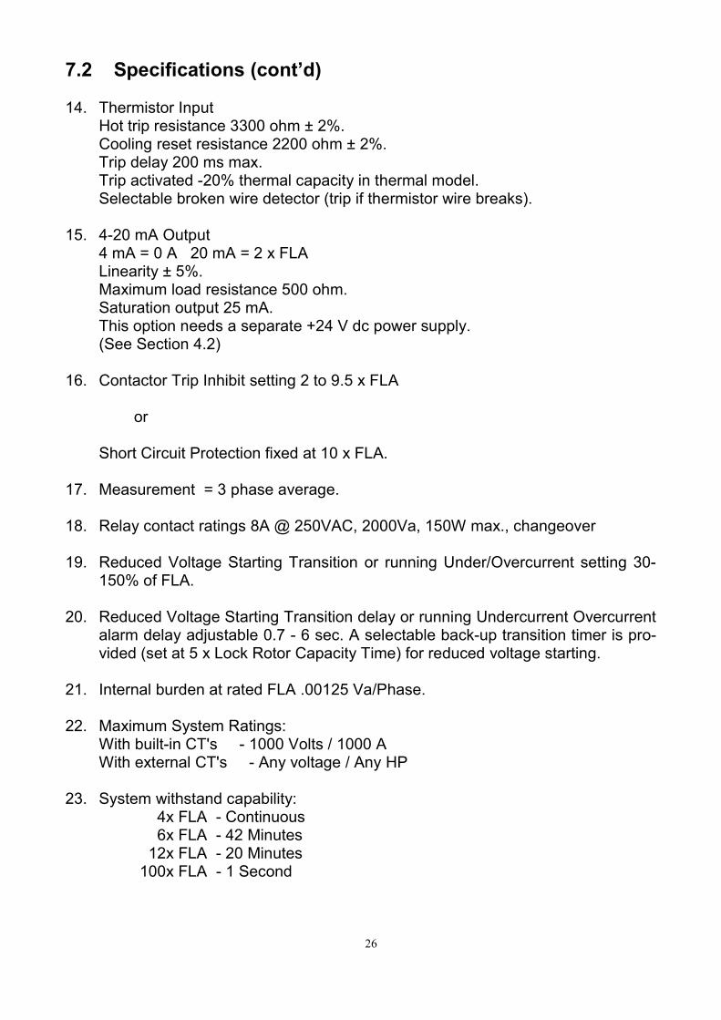
7.2 Specifications (cont’d) 14. Thermistor Input Hot trip resistance 3300 ohm ± 2%. Cooling reset resistance 2200 ohm ± 2%. Trip delay 200 ms max. Trip activated -20% thermal capacity in thermal model. Selectable broken wire detector (trip if thermistor wire breaks). 15. 4-20 mA Output 4 mA = 0 A 20 mA = 2 x FLA Linearity ± 5%. Maximum load resistance 500 ohm. Saturation output 25 mA. This option needs a separate +24 V dc power supply. (See Section 4.2) 16. Contactor Trip Inhibit setting 2 to 9.5 x FLA or Short Circuit Protection fixed at 10 x FLA. 17. Measurement = 3 phase average. 18. Relay contact ratings 8A @ 250VAC, 2000Va, 150W max., changeover 19. Reduced Voltage Starting Transition or running Under/Overcurrent setting 30-
150% of FLA. 20. Reduced Voltage Starting Transition delay or running Undercurrent Overcurrent
alarm delay adjustable 0.7 - 6 sec. A selectable back-up transition timer is pro-vided (set at 5 x Lock Rotor Capacity Time) for reduced voltage starting.
21. Internal burden at rated FLA .00125 Va/Phase. 22. Maximum System Ratings: With built-in CT's - 1000 Volts / 1000 A With external CT's - Any voltage / Any HP 23. System withstand capability: 4x FLA - Continuous 6x FLA - 42 Minutes 12x FLA - 20 Minutes 100x FLA - 1 Second
26

7.2 Specifications (cont’d) 24. Motor Protection Unit frequency range 10-200 Hz. (With option LF, frequency range 2—200Hz) 25. Noise immunity 2KV spark test. 26. R.F. interference tested at 10 Volts/Meter. 27. Temperature Range -10 to +60°C (operating) -50 to +80°C (storage) 28. Shock tested per CEGB Spec. #E/TSS/EX12021 & IEC 68-2-27 to 60G. 29. Optional external core balance CT 500:1 (Current Level = 1mA at .5 Amp Ground Fault Level) 30. Optional internal ground fault test (1 A level). 31. Optional Logic Relay Unit. 32. Standard spill current method of ground fault detection on models C&D.
27

7.3 Unit Dimensions & weight
8.0 Options
8.1 Low Frequency (LF) For use with soft starters all MSP-4 units can be supplied woth this option. Frequency range 2—200Hz Single phase response = 4 sec
8.2 External Core Balance CT (Models A and B only) The MSP-CB core balance CT's are low priced, enclosed versatile models having inside diameters of 28, 90, and 140mm. For setting ground fault trip currents etc., refer to Section 5. For additional information, refer to the instruction included with each unit.
Dimensions in mm, Weight in gram
ions (in mm, aprox.) Types W H D Cable hole
MSP-4-AI-EP MSP-4-BI-EP MSP-4-CI-EP MSP-4-DI-EP MSP-4-AT500-EP MSP-T500
150 150 150 150 150 200
70 70 70 70 70 70
96 96 96 96 96 96
Stud mount 16 16 16 Stud mount 28
MSP-4-M MSP-4-MIP
130 90 42 Door cut-out 121 x 82
MSP-P/P-1 MSP-P/P-DIN-1 MSP-P/P-CL-01 LRU
45 45 68 55
55 70 35 70
25 90 52 90
Weight
940 940 940 940 940 1720
380 380
160 400 400 240
28

8.3 Power Packs
MSP-4 POWER PACK OVERVIEW
———————————————————————————–—————–—————— SUPPLY PART NUMBER VOLTAGE OUTPUT USED FOR... —————————————————————————–———–——————–———– MSP P/P-1 110-230Vac 15Vac max Power pack or MSP P/P-DIN-1 110-440Vac Remote reset ——————————————————————————–————–————––——— MSP P/P-CL-01 115Vac 24Vdc,50mA 4-20mA CURRENT LOOP MSP P/P-DIN-CL-00 230Vac MSP P/P-DIN-CL-01 115Vac —————————————————————————–———–——————–———– MSP P/P-DIN-ICB-2 110-220Vac 15Vac max. plus Power pack and G/F test 1Amp G/F test For INTERNAL Core Balance With local test button MSP P/P-DIN-ECB-2 110-440Vac 15Vac max. plus Power pack and G/F test 1Amp G/F test For EXTERN Core Balance With local test button —————————————————————————————————–——–———
8.4 Logic relay units
This unit provides additional outputs to increase the flexibility and control capabilities of the MSP-4. It also provides power to the MSP-4. The LRU has the following output contacts: - Motor ready (Thermal Capacity is sufficient to start, and no trip) - Up-stream trip on short circuit - Up-to-speed signal (for cascade control or monitoring) For additional information, refer to instruction enclosed with each Logic Relay Unit.
29

9.0 Typical Applications (Where MSP-4 offers full system protection) 1. The feature of inhibiting the contactor from opening above a predetermined level
and allowing the fuses or breaker to clear protects the contactor as well as the motor and avoids excessive down time. Also Upstream Breaker Tripping is possi-ble.
2. Star/delta or auto transformer transition under current instead of time gives a new
outlook to this method of starting and ensures optimum transition at optimum torque at the most economical price.
3. Warning of overload through an auxiliary protection relay after a fixed time period,
before the motor trips out, gives the capability of taking corrective action before a shut down, thereby avoiding production loss.
4. Switching in extra motors during peak demands, or to control flow level to opti-
mum load conditions. 5. Accurate undercurrent detection operating on an independent relay for conveyor
belt breakage, etc. can be used to avoid spillage. 6. Loss of fluid to pumps is the biggest cause of pump failure either by blockage or
critical level reduction. Accurate measurement of undercurrent allows loss of fluid detection without having to use pressure switches and level controls which are prone to environmental failure.
7. Pumps which start and stop automatically can be subjected to heavy back pres-
sure on the couplings. This is especially relevant when a pump stops and starts quickly without allowing the back pressure to settle, (i.e. down hole pumping). Re-starting into fluid back pressure causes up to twice the torque demand to be ex-erted on the coupling. A combination of undercurrent detection and an external time delay provides the solution.
8. Electronic shearpin detection (mechanical jam). With the advent of motors having
a 1.0 service factor, the tendency is to oversize motors to create an artificial level of service factor. This creates an unbalance in the electrical to mechanical torque. On motor couplings and gear boxes a stall occurring because of a mechanical jam results in the electrical torque being too high for the mechanical torque capa-bility. Mechanical damage occurs. By use of the electronic shearpin this can be avoided.
30

10.0 Typical System Configuration
Model C& D (5A—125 Amps)
L1
L2
L3
MSP-4
P1
TRIPRELAY
AUXRELAY
R1
R2E/F
COREBALANCE
P2
P1 P2
P1 P2
S1 S2
S1
S1
S2
S2
3 line current transformers configuration
For High voltage application make surethe startpoint at the MSP-4 side isconnected to Earth as close as possible
31

10.1 Typical System Configuration Model A & B (0,13A 6501 Amps)
I. NOM. (A)
I. STALL (%)
T. STALL (ms)
THERM' CAP. (s)
RESET LEVEL (%)
AUX' LEVEL (%)
1
2
3
4
5
6
8
9
10
11
12
13
14
15
16
17
NO
C
NC
R1
NO
C
NC
POWER PACK
G/F INPUT
MSP-4
R2
1 2 3 4 5 6 7 REMOTEDISPLAY
RESET
LRU
MSP - MONITOR - B
VALUE CODE
READ/SET FAULT
START
LEVEL
0 I. PRIMARY (A)1 I. NOMINAL (A)2 STALL LEVEL (%)3 STALL TIME (ms)
4 THERM' CAP. (s)5 RESET LEVEL (%)6 AUX' LEVEL (%)7 RES'CAP (%)
0 S/C1 INH. START2 STALL3 O/L4 PH' LOSS5 PH' REV'6 GROUND7 NO FAULT
1- THERMISTORTRIPRESET FAULTREAD/SET
32

Typical System Configuration (cont'd)
33

Typical System Configuration (cont'd)
34

Typical System Configuration (cont'd)
35

11.0 Location of Internal Components
0.51
1.522.53
0123456789ABCDEF7.5
76.565.554.543.5
1.0
22.633.544.555.566.577.588.599.5
L% Iav
ON
no override
U/C
O/C
O/C
INHIBITON
OFF
ON
OFFG/F
ON OFF
Ph. loss
Ph. rev
Short Circuit
RESET
OFF
auto reset
0
7
ON
OFF
1
2
3
4
5
6
78
9
10
11
12
13
14
15
16
17
36

12.0 Quick start
14 Easy Steps to a Safe Start 1. Install MSP-4 and connect the power
Pack. 2. Plug MSP monitor into the MSP-4 3. Wire your "overload trip" circuit to R1 nor-
mally closed contacts on the MSP-4 Ter-minals 9 and 10.
4. Thread the 3 motor leads (or secondary
leads of interposing CT’s) through the 3 openings in the MSP-4. (or connect to the studs of the MSP-4-AIP or MSP-4-AT4500).
5. If interposing CT’s are used, ensure you
ground 1 side of each CT as close as pos-sible to the MSP-4
6. Apply Controls Voltage to the Power Pack 7. Press the "RELAY TEST" button on the
back of the Monitor, to check R1 and R2 relay operation. (and your "overload trip" circuit).
STEPS 8 AND 9 APPLY TO ALL MSP-4 RELAYS EXCEPT FOR MSP-4-AIP AND MSP-4-BIP RELAYS, FOR THOSE RE-FER TO "SET UP INSTRUCTION MSP-AIP AND MSP-BIP", TO SET-UP POT NUMBERS 1 AND 7, THEN PROCEED TO STEP NUM-BER 10. (see 5.4)
8. Pulse the Monitor's "READ/SET" button
until CODE "1" appears on the display. 9. Holding the "READ/SET" button de-
pressed, continuously displays CODE "1". Use a screwdriver to adjust Pot 1 on the MSP-4, until the "VALUE" displayed matches the Full Load Current (obtained from the motor nameplate).
10. Pulse the READ/SET button until CODE
"4" appears then hold continuously. Use a screwdriver to adjust Pot4 until the
”VALUE” is displayed matches the motor Thermal Capacity at 6 times full load cur-rent. (This is sometimes referred to as Maximum Stall Time). This information is available from the motor manufacturer.
IF THIS IS NOT AVAILABLE, REFER TO SECTION “SETTINGS—MOTOR THER-MAL CAPACITY”(see 5.3 / 4)
11. Pulse the READ/SET button until CODE
“7” appears. The reading under “VALUE” should be “100”, representing 100% Thermal Capacity
BEFORE THE NEXT STEP, MAKE SURE THE MOTOR IS CONNECTED TO ITS NORMAL LOAD SO YOU OBTAIN A REPRESENTATIVE READING ON THERMAL CAPACITY USED DURING THE START
12. Holding the READ/SET button on CODE
“7”, start the motor and observe the low-est reading. This is the amount of thermal capacity remaining after 1 cold start.
13. Subtract the value read in step 12 from
100% to give the Percent Thermal capac-ity used for the start. Add 10% of the used capacity to allow for slight variations in load and voltage during future starts. Example: The lowest value displayed on CODE “7” was 70%. 100%-70% = 30% + (10% x 30) = 33%
14. Pulse the READ/SET button until CODE
“5” appears, then hold continuously. Use a screwdriver to adjust pot 5 until the “VALUE” displayed matched the amount calculated in step 13 (in this example = 33).
If you did not stop the motor, you will see the thermal capacity reading on CODE “7” gradually increased to 80%. This is the nor-mal capacity of a motor running at full load. You may wish to stop the motor now. YOUR MSP-4 IS NOW OPERATIONAL
37

MSP-4 MOTOR PROTECTION SYSTEM
Alectryon
P.O. BOX 442 7550 AK Hengelo
Holland Tel +31(0)74 250 08 55 Fax +31(0)74 242 96 01
www.alectryon.nl [email protected]
REVISED Feb 2009 RRINTED IN HOLLAND
HOLLAND