Embed Size (px)
Citation preview

SCHURTER GmbH D – 79346 Endingen www.schurter.com
Changes that contribute to technical improvement are subject to alternations
page issue date: created by: amendment date: released by: amendment no.: datasheet no.: index
1 of 16 04.08.2007 Mangold 07.12.2010 Schillak 10321 105.9526.200 h
Print date: 10/12/2010 14:40:00
Product Manual
Vandal-proof latching action switch MSM LA
CONTENTS
1 PRODUCT DESCRIPTION ............................................................................................... 2
2 TECHNICAL DATA AND DIMENSIONAL DRAWINGS ................................................... 2
2.1 Technical Data ...................................................................................................................... 2
2.2 Dimensional Drawings ......................................................................................................... 5
2.3 Hole Dimensions ................................................................................................................... 7
2.4 Starting Torque ...................................................................................................................... 7
2.5 Switching Symbols ................................................................................................................ 8
2.6 Contact Layout ...................................................................................................................... 9
3 ORDER NUMBERS ........................................................................................................ 10
3.1 Order Numbers MSM LA ................................................................................................... 10
3.2 Lettering ................................................................................................................................ 11
4 ASSEMBLY .................................................................................................................... 13
4.1 Installation ............................................................................................................................ 13
5 PACKAGING .................................................................................................................. 14
6 QUALIFICATION TEST .................................................................................................. 15
6.1 IP Protection Class ............................................................................................................. 15
6.2 IK Protection Class ............................................................................................................. 15
6.3 ESD Protection .................................................................................................................... 15
6.4 Salt Spray Test .................................................................................................................... 15
7 APPROVALS .................................................................................................................. 16
8 COMPLIANTS................................................................................................................. 16

SCHURTER GmbH D – 79346 Endingen www.schurter.com
Changes that contribute to technical improvement are subject to alternations
page issue date: created by: amendment date: released by: amendment no.: datasheet no.: index
2 of 16 04.08.2007 Mangold 07.12.2010 Schillak 10321 105.9526.200 h
Print date: 10/12/2010 14:40:00
1 PRODUCT DESCRIPTION
- housing and actuator are made of high-quality stainless steel - switch is particularly suitable for use in equipment in harsh environments or for vandal-
protected applications - available with mounting diameters of 19 and 22 mm - suitable for use in temperatures ranging from -20 °C to+85 °C - permissible switching voltages up to 125 VDC / 250 VAC - switching status (ON/OFF) is easy to discern by looking at, or feeling, the resting position
of the actuator; in the off state, the actuator position protrudes from the housing; in the ON state, it is depressed into the housing
- with quick connect terminals to allow for fast connections - point and ring illuminated versions in red, green and blue are available for indicating the
switching status or for providing visibility during night-time use - available in single-pole and double-pole versions
2 TECHNICAL DATA AND DIMENSIONAL DRAWINGS
2.1 Technical Data
Electrical Data
Switching Voltage max. [VDC] 30 (125VDC/0,5A)1)
Switching Voltage max. [VAC] 250
Switching Current max. [AAC] 12
Rated Braking Capacity [WAC] 3000
Lifetime (at 8A / 250 VAC) [Actuations] 50.000
Lifetime 1)
(at 0,5A / 125 VDC) [Actuations] 100.000
Initial Contact Resistance (at 12V / 1 ADC)
[mΩ] < 100
Insulation Resistance (500 VDC) [MΩ] > 100
1) Direct current Lifetime testing accomplished for switch element 1682.1101 with an actuation frequency of 1 Hz and an actuation velocity of 100 mm/s.
SCHURTER GmbH D – 79346 Endingen www.schurter.com
Changes that contribute to technical improvement are subject to alternations
page issue date: created by: amendment date: released by: amendment no.: datasheet no.: index
3 of 16 04.08.2007 Mangold 07.12.2010 Schillak 10321 105.9526.200 h
Print date: 10/12/2010 14:40:00
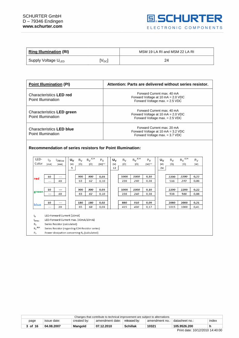
Ring Illumination (RI) MSM 19 LA RI and MSM 22 LA RI
Supply Voltage ULED [VDC] 24
Point Illumination (PI) Attention: Parts are delivered without series resistor.
Characteristics LED red Point Illumination
Forward Current max. 40 mA Forward Voltage at 10 mA = 2.0 VDC
Forward Voltage max. = 2.5 VDC
Characteristics LED green Point Illumination
Forward Current max. 40 mA Forward Voltage at 10 mA = 2.0 VDC
Forward Voltage max. = 2.5 VDC
Characteristics LED blue Point Illumination
Forward Current max. 20 mA Forward Voltage at 10 mA = 3.2 VDC
Forward Voltage max. = 3.7 VDC
Recommendation of series resistors for Point Illumination:

SCHURTER GmbH D – 79346 Endingen www.schurter.com
Changes that contribute to technical improvement are subject to alternations
page issue date: created by: amendment date: released by: amendment no.: datasheet no.: index
4 of 16 04.08.2007 Mangold 07.12.2010 Schillak 10321 105.9526.200 h
Print date: 10/12/2010 14:40:00
Mechanical Data
Actuating Force typ. [N] 10
Actuating Travel typ. [mm] 5.2
Lifetime mechanical [Actuations] 100.000
Contact Gap [mm] 3
Shock Resistance (DIN EN 50102)
[IK] 07
Starting Torque MSM 19 LA MSM 22 LA
Plastic Nut max. [Nm] 4.5 3.5
Stainless Steel Nut* max. [Nm] 12 16
* on request
Climatic Data
Operating Temperature [°C] -20 to +85
Storage Temperature [°C] -20 to +85
Degree of Protection (DIN EN 60529)
[IP] IP 64 Front Side IP 00 Rear Side
Material
Component Material with flammability rating
Push button holder PA66 (UL94-V0 related to d ≥ 1.6 mm)
Intermediate Connector PA66 (UL94-V0 related to d ≥ 1.6 mm)
Contact Pin Adapter PA66 (UL94-V0 related to d ≥ 1.6 mm)
Component Material without flammability rating
Housing Stainless Steel 1.4305
Actuator (disc, outside housing) Stainless Steel 1.4305
Illuminated Ring (die-casting, inside housing) PC
Sealing Ring NBR70
SCHURTER GmbH D – 79346 Endingen www.schurter.com
Changes that contribute to technical improvement are subject to alternations
page issue date: created by: amendment date: released by: amendment no.: datasheet no.: index
5 of 16 04.08.2007 Mangold 07.12.2010 Schillak 10321 105.9526.200 h
Print date: 10/12/2010 14:40:00
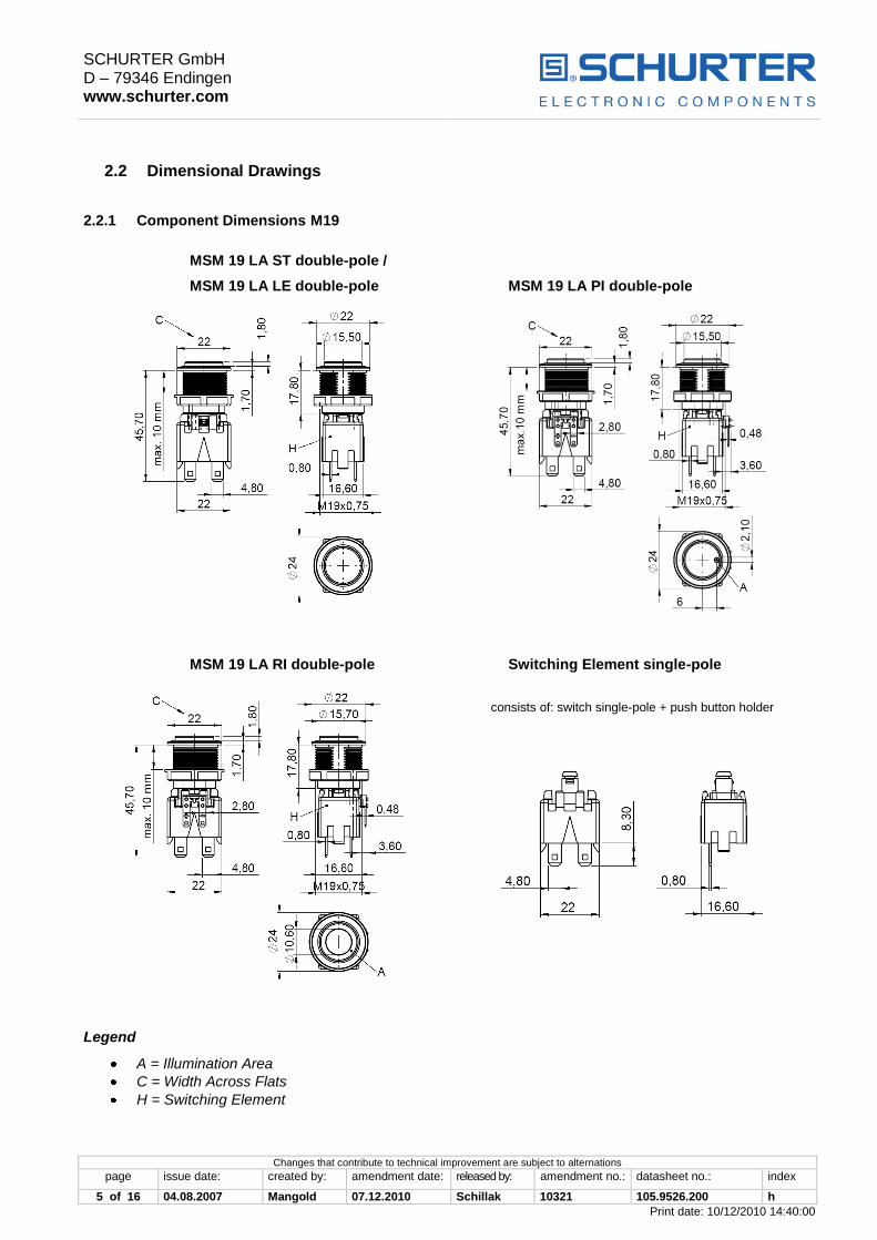
2.2 Dimensional Drawings
2.2.1 Component Dimensions M19
MSM 19 LA ST double-pole /
MSM 19 LA LE double-pole MSM 19 LA PI double-pole
MSM 19 LA RI double-pole Switching Element single-pole
consists of: switch single-pole + push button holder
Legend
A = Illumination Area
C = Width Across Flats
H = Switching Element

SCHURTER GmbH D – 79346 Endingen www.schurter.com
Changes that contribute to technical improvement are subject to alternations
page issue date: created by: amendment date: released by: amendment no.: datasheet no.: index
6 of 16 04.08.2007 Mangold 07.12.2010 Schillak 10321 105.9526.200 h
Print date: 10/12/2010 14:40:00
2.2.2 Component Dimensions M22
MSM 22 LA ST double-pole /
MSM 22 LA LE double-pole MSM 22 LA PI double-pole
MSM 22 LA RI double-pole Switching Element single-pole
consists of: switch single-pole + push button holder
Legend
A = Illumination Area
D = Knurled Nut
H = Switching Element

SCHURTER GmbH D – 79346 Endingen www.schurter.com
Changes that contribute to technical improvement are subject to alternations
page issue date: created by: amendment date: released by: amendment no.: datasheet no.: index
7 of 16 04.08.2007 Mangold 07.12.2010 Schillak 10321 105.9526.200 h
Print date: 10/12/2010 14:40:00
2.3 Hole Dimensions
MSM 19 LA (without torsion protection) MSM 19 LA (with torsion protection)
+0,1
19,1
18,15+0,05
19,1
+0,1
MSM 22 LA (without torsion protection) MSM 22 LA (with torsion protection)*
+0,1
22,1
22,1
+0,1
21,15+0,05
* Hole Dimensions with torsion protection:
- recommended for version „Ring Illumination“
- required for version „Point Illumination“ and „Lettered”
2.4 Starting Torque
Plastic Nut max. (Nm) Stainless Steel Nut * max. (Nm)
MSM 19 4.5 12
MSM 22 3.5 16
* on request
SCHURTER GmbH D – 79346 Endingen www.schurter.com
Changes that contribute to technical improvement are subject to alternations
page issue date: created by: amendment date: released by: amendment no.: datasheet no.: index
8 of 16 04.08.2007 Mangold 07.12.2010 Schillak 10321 105.9526.200 h
Print date: 10/12/2010 14:40:00
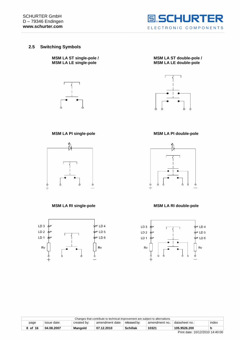
2.5 Switching Symbols
MSM LA ST single-pole / MSM LA ST double-pole / MSM LA LE single-pole MSM LA LE double-pole
MSM LA PI single-pole MSM LA PI double-pole
MSM LA RI single-pole MSM LA RI double-pole
SCHURTER GmbH D – 79346 Endingen www.schurter.com
Changes that contribute to technical improvement are subject to alternations
page issue date: created by: amendment date: released by: amendment no.: datasheet no.: index
9 of 16 04.08.2007 Mangold 07.12.2010 Schillak 10321 105.9526.200 h
Print date: 10/12/2010 14:40:00
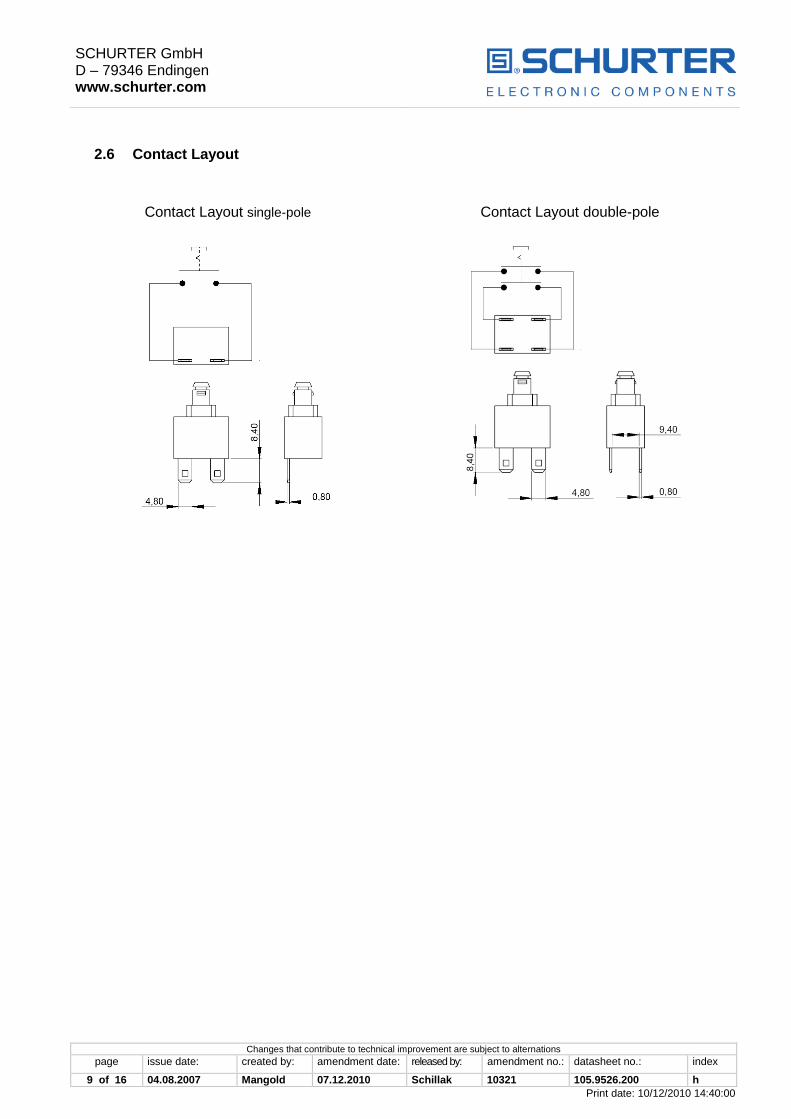
2.6 Contact Layout
Contact Layout single-pole Contact Layout double-pole

SCHURTER GmbH D – 79346 Endingen www.schurter.com
Changes that contribute to technical improvement are subject to alternations
page issue date: created by: amendment date: released by: amendment no.: datasheet no.: index
10 of 16 04.08.2007 Mangold 07.12.2010 Schillak 10321 105.9526.200 h
Print date: 10/12/2010 14:40:00
3 ORDER NUMBERS
3.1 Order Numbers MSM LA
Mounting Diameter (mm) Ø 19 Ø 22
Latching Action Switch, single-pole
ST (Standard) 1241.6821.1110000 1241.6831.1110000
LE (Lettering) * 1241.6822.1110XXX 1241.6832.1110XXX
PI (Point Illumination) red 1241.6823.1111000 1241.6833.1111000
PI (Point Illumination) green 1241.6823.1112000 1241.6833.1112000
PI (Point Illumination) blue 1241.6823.1114000 1241.6833.1114000
RI (Ring Illumination) red 1241.6824.1111000 1241.6834.1111000
RI (Ring Illumination) green 1241.6824.1112000 1241.6834.1112000
RI (Ring Illumination blue 1241.6824.1114000 1241.6834.1114000
Latching Action Switch, double-pole
ST (Standard) 1241.6821.1120000 1241.6831.1120000
LE (Lettering) * 1241.6822.1120XXX 1241.6832.1120XXX
PI (Point Illumination) red 1241.6823.1121000 1241.6833.1121000
PI (Point Illumination) green 1241.6823.1122000 1241.6833.1122000
PI (Point Illumination) blue 1241.6823.1124000 1241.6833.1124000
RI (Ring Illumination) red 1241.6824.1121000 1241.6834.1121000
RI (Ring Illumination) green 1241.6824.1122000 1241.6834.1122000
RI (Ring Illumination) blue 1241.6824.1124000 1241.6834.1124000
* Lettering Index see under chapter 3.2
SCHURTER GmbH D – 79346 Endingen www.schurter.com
Changes that contribute to technical improvement are subject to alternations
page issue date: created by: amendment date: released by: amendment no.: datasheet no.: index
11 of 16 04.08.2007 Mangold 07.12.2010 Schillak 10321 105.9526.200 h
Print date: 10/12/2010 14:40:00
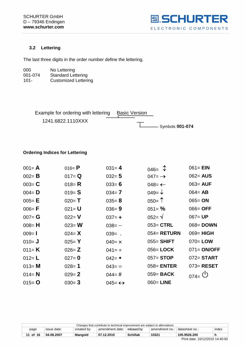
3.2 Lettering
The last three digits in the order number define the lettering. 000 No Lettering 001-074 Standard Lettering 101- Customized Lettering
Example for ordering with lettering Basic Version
1241.6822.1110XXX Symbols 001-074 Ordering Indices for Lettering
001= A 016= P 031= 4 046= 061= EIN
002= B 017= Q 032= 5 047= 062= AUS
003= C 018= R 033= 6 048= 063= AUF
004= D 019= S 034= 7 049= 064= AB
005= E 020= T 035= 8 050= 065= ON
006= F 021= U 036= 9 051= % 066= OFF
007= G 022= V 037= 052= 067= UP
008= H 023= W 038= 053= CTRL 068= DOWN
009= I 024= X 039= 054= RETURN 069= HIGH
010= J 025= Y 040= 055= SHIFT 070= LOW
011= K 026= Z 041= 056= LOCK 071= ON/OFF
012= L 027= 0 042= 057= STOP 072= START
013= M 028= 1 043= 058= ENTER 073= RESET
014= N 029= 2 044= 059= BACK 074=
015= O 030= 3 045= 060= LINE

SCHURTER GmbH D – 79346 Endingen www.schurter.com
Changes that contribute to technical improvement are subject to alternations
page issue date: created by: amendment date: released by: amendment no.: datasheet no.: index
12 of 16 04.08.2007 Mangold 07.12.2010 Schillak 10321 105.9526.200 h
Print date: 10/12/2010 14:40:00
Font Size
MSM 19 LA LE / MSM 19 LA PI :
Single characters: height 8 mm, font: Helvetica normal DIN1451-1E Text, max. 3 characters height 3 mm, font: Helvetica normal DIN1451-1E Text, max. 6 characters: height 2.5 mm, font: Helvetica condensed DIN1451-3E Symbols (indices 037-052): capitals height 8 mm, font: True Type, Symbol
MSM 22 LA LE / MSM 22 LA PI :
Single characters: height 8 mm, font: Helvetica normal DIN1451-1E Text, max. 3 characters height 5 mm, font: Helvetica normal DIN1451-1E Text, max. 6 characters: height 2.5 mm, font: Helvetica condensed DIN1451-3E Symbols (indices 037-052): capitals height 8 mm, font: True Type, Symbol
MSM 19 LA RI * / MSM 22 LA RI *:
Single characters: height 5 mm, font: Helvetica normal DIN1451-1E Text, max. 3 characters height 3 mm, font: Helvetica normal DIN1451-1E Symbols (indices 037-052): capitals height 5 mm, font: True Type, Symbol
* At a minimum order quantity of 100 pieces the ring illuminated version with lettering is available on request.
SCHURTER GmbH D – 79346 Endingen www.schurter.com
Changes that contribute to technical improvement are subject to alternations
page issue date: created by: amendment date: released by: amendment no.: datasheet no.: index
13 of 16 04.08.2007 Mangold 07.12.2010 Schillak 10321 105.9526.200 h
Print date: 10/12/2010 14:40:00
4 ASSEMBLY
4.1 Installation
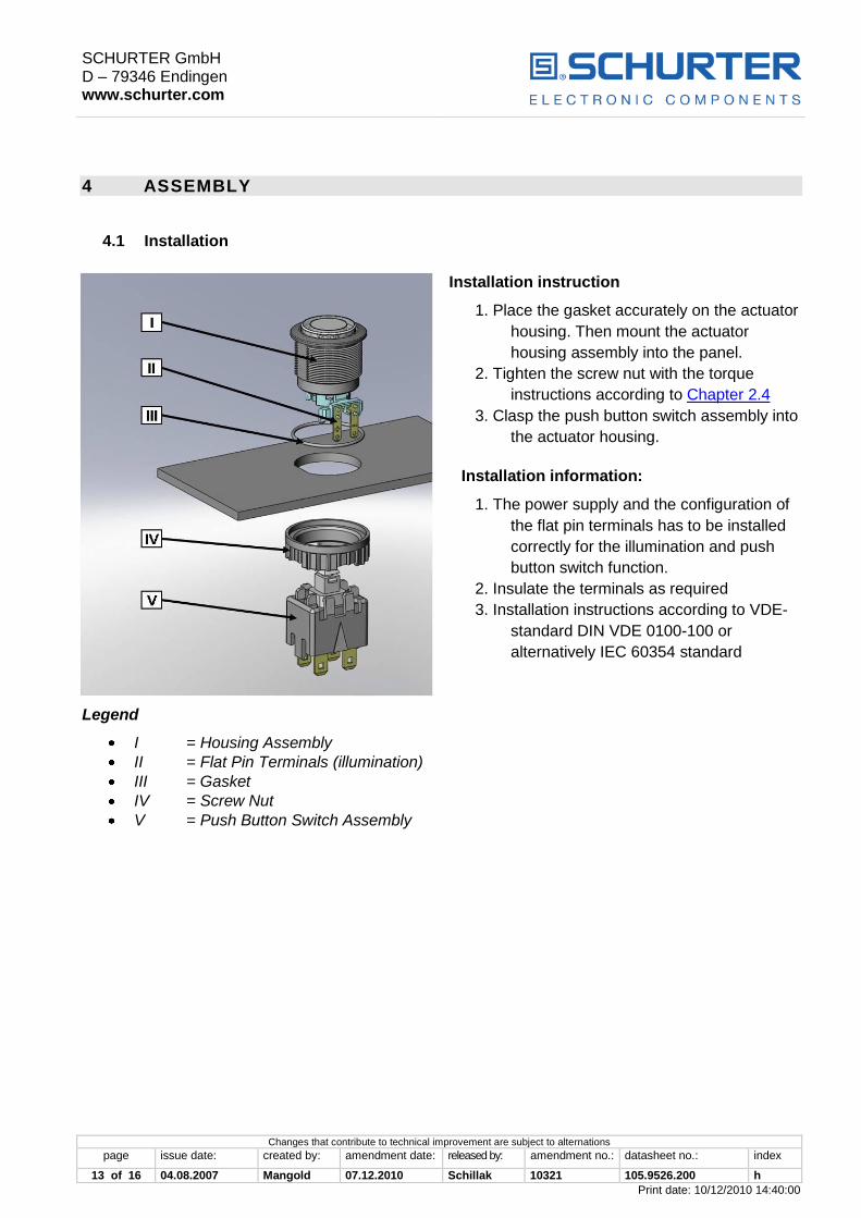
Installation instruction
1. Place the gasket accurately on the actuator
housing. Then mount the actuator
housing assembly into the panel.
2. Tighten the screw nut with the torque
instructions according to Chapter 2.4
3. Clasp the push button switch assembly into
the actuator housing.
Installation information:
1. The power supply and the configuration of
the flat pin terminals has to be installed
correctly for the illumination and push
button switch function.
2. Insulate the terminals as required
3. Installation instructions according to VDE-
standard DIN VDE 0100-100 or
alternatively IEC 60354 standard
Legend
I = Housing Assembly
II = Flat Pin Terminals (illumination)
III = Gasket
IV = Screw Nut
V = Push Button Switch Assembly
SCHURTER GmbH D – 79346 Endingen www.schurter.com
Changes that contribute to technical improvement are subject to alternations
page issue date: created by: amendment date: released by: amendment no.: datasheet no.: index
14 of 16 04.08.2007 Mangold 07.12.2010 Schillak 10321 105.9526.200 h
Print date: 10/12/2010 14:40:00
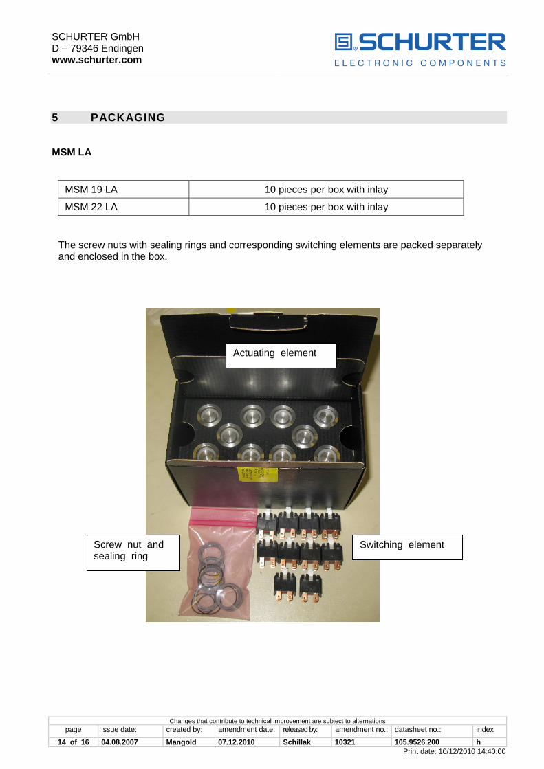
5 PACKAGING
MSM LA
MSM 19 LA 10 pieces per box with inlay
MSM 22 LA 10 pieces per box with inlay
The screw nuts with sealing rings and corresponding switching elements are packed separately and enclosed in the box.
Actuating element
Screw nut and sealing ring
Switching element

SCHURTER GmbH D – 79346 Endingen www.schurter.com
Changes that contribute to technical improvement are subject to alternations
page issue date: created by: amendment date: released by: amendment no.: datasheet no.: index
15 of 16 04.08.2007 Mangold 07.12.2010 Schillak 10321 105.9526.200 h
Print date: 10/12/2010 14:40:00
6 QUALIFICATION TEST
6.1 IP Protection Class
IP Protection Class IEC/DIN/EN/60529 IP 64 Front Side
IP 00 Rear Side
6.2 IK Protection Class
Tested centrically
IK Protection Class DIN EN 50102 IK 07
6.3 ESD Protection
ESD test according to DIN 61000-4-2:
4kV Contact Discharge MSM LA ST
MSM LA LE Ø 19; 22 mm
6.4 Salt Spray Test
Salt spray test according to DIN 50021- SS 24h, 48h and 96h residence time
The surface of the stainless steel material is covered with a molecular-passive layer. Only under very unfavourable conditions it is possible, that iron and rust molecules as well as base metals penetrate the passive layer as foreign substances (pollutions) and initiate the rust process.
The smoothness of the actuator was not affected. After the residence time the tested samples were cleaned under running water and all rust spots could be removed.

SCHURTER GmbH D – 79346 Endingen www.schurter.com
Changes that contribute to technical improvement are subject to alternations
page issue date: created by: amendment date: released by: amendment no.: datasheet no.: index
16 of 16 04.08.2007 Mangold 07.12.2010 Schillak 10321 105.9526.200 h
Print date: 10/12/2010 14:40:00
7 APPROVALS
The listed approvals only refer to the push button switch and not to the complete switch.
Push button switch:
Type Identification Number ENEC
VDE / KEMA
UL 1054
CSA C22.2 NO55
1681.1101 KEMA 2106068.01 DIN EN 61058 E41791
1682.1101 KEMA 2106068.01 DIN EN 61058 E41791
8 COMPLIANTS
All articles are ROHS-compliant and in compliance to the Low Voltage Directive (2006/95/EC).


