Embed Size (px)
Citation preview

MSI
SINGLE IDLER BELT SCALE
Instruction Manual
PL-319
February 1992
33453190PRR 1.1

Thank you for purchasing Milltronics� products. We endeavour to design
equipment that is simple to use and reliable in its operation, with the aim of
satisfying our customers� needs.
Milltronics has been designing and manufacturing process equipment since 1954.
Our fields of expertise include ultrasonic level measurement, in-line weighing of
dry bulk solids and motion sensing.
Milltronics is established world wide through associate offices and repre-
sentatives. Our network is continually being refined to provide our customers
with first rate sales information, engineering assistance and after sales support.
For more details on our products and service, please contact us and we will provide
you with a listing of the offices or representatives nearest you.
P.O. Box 4225730 The KingswayPeterborough, ONCanada K9J 7B1
709 Stadium Drive Arlington, TexasU.S.A. 76011
Oak House Everoak EstateBromyard RoadWorcester, WR2-5HPEngland
Château de la SaurinePont de BayeuxB.P. 613590 MeyreuilAix en ProvenceFrance
Tel. (705) 745-2431Fax (705) 745-0414
Tel. (817) 277-3543Fax (817) 277-3894
Tel. (01905) 748404Fax (01905) 748430
Tel. 42.65.69.00Fax 42.58.63.95

TABLE OF CONTENTS
Title Page
ABOUT THIS MANUAL 1
ABOUT THE MSI 1
SPECIFICATIONS 2
OPERATION 3
INSTALLATIONIntroduction 4Welding 4Load Cell Handling 4Installation Procedure 5
CALIBRATIONGeneral 9Test Load 9Zero 9Span 9Material Test 10Re-Rating 10
MAINTENANCE 10
IDLER MOUNTING
Troughed Idler with Channel Spine 11Troughed Idler with Pipe Spine 12Flat Idler 13
MSI WIRING 14
OUTLINE DIMENSIONS - CEMA 15
OUTLINE DIMENSIONS - METRIC 16


ABOUT THIS MANUAL
This instruction manual covers the installation, operation and maintenance of the MSI belt scale.
We strongly recommend that the user read this manual before installation and start up of any component of theweighing system to which the MSI is being applied. Adhering to the installation and operating procedures willinsure a quick, trouble free installation and allow for the maximum accuracy and rel iability of your weighing system.
Because the MSI belt scale is used in conjunction with an integrator and speed sensor, the instruction manualscovering these components should be read as well.
ABOUT THE MSI
The Milltronics Single Idler (MSI) is a belt scale designed to be inserted into belt conveyors for continuousweighing of dry bulk solids.
The MSI belt scale includes: - one weighbridge c/w two load cells with leads run in liquid tite conduit and 150 cm (5’) of interconnecting cable terminated
with lugs and conduit fitting.
- test weight(s)
The addition of an idler (supplied and installed by customer) to the wei ghbridge completes the weighing assembly.The MSI load cells provide an electronic signal, proportional to load, which is fed to the Milltronics integrator.Thus, weighing is accomplished without interrupting the process and without affecting the process material.
It is important to understand that the MSI is an accurate and repeatable force sensor. Its performance is ultimatelydependent upon the conveyor system and the quality of the instal lation and alignment.
PL-319 1

SPECIFICATIONS
Accuracy: » ± 0.5% of totalization over 5 to 1 operating range
Belt Width: » 18" to 96" in CEMA sizes» 500 to 2000 mm in metric sizes» refer to Outline Dimensions section
Belt Speed: » up to 4 m/s (800 fpm)
Capacity: » up to 5000 TPH at maximum belt speed
Conveyor Incline: » ± 20° from horizontial, fixed incline» up to ± 30° with reduced accuracy
Conveyor Idler: » flat to 35°» up to 45° with reduced accuracy
Idler Diameter: » 50 to 180 mm (2 to 7")
Idler Spacing: » 0.5 to 1.5 m (1.5 to 5.0 ft)
Load Cell: » excitation: » 10 V DC nominal» 15 V DC maximum
» output: » 2 mV / V excitation at rated load cell capacity
» non-linearity: » 0.02% of rated output
» hysteresis: » 0.02% of rated output
» non-repeatability: » 0.01% of rated output
» capacity: » maximum ranges: 50, 100, 250, 500, 750,1000 lb
» overload: » safe 150% of rated capacity ultimate 300% of rated capacity
» temperature: » – 40 to 85 °C (– 40 to 185 °F) operating range
» – 18 to 65 °C ( 0 to 150 °F) compensated
» mounting dims: » identical for all capacities
Approvals: » CSA certified for general purpose
Hazardous Locations: » with the use of approved intrinsically safe barrier strips
Weight: » see chart, Outline Dimensions section
The combination of capacity, speed and idler spacing must result in a usable conveyor belt loading value.
PL-319 2

OPERATION
idler frame
scale mountingbracket
dynamic beam
static beam
test weight baridler mounting bracket
Force
idler clip
The MSI weighbridge is designed to react only to the vertical component of the force being applied to it. The MSIconsists essentially of a fixed support frame (static) and a live frame (dynamic).
The static frame is the main scale support between the conveyor stringers which in turn supports the dynamicframe including the load cells.
The dynamic frame supports the scale idler and transfers the weight of the material to the load cells.
As the material travels along the conveyor belt, a force is exerted through the suspended idler to the dynamicframe. The dynamic frame is forced down proportionally. The movement in the load cell is sensed by its straingauges when excited by voltage from the electronic integrator and produces a signal proportional to weight, whichis returned to the integrator. The movement in each load cell is limited by the positive stop incorporated in thedesign of the load cell.
weighbridge
PL-319 3

INSTALLATION
INTRODUCTION
The MSI is shipped from the factory as a single unit attached to a shipping frame for protection. The unit mustbe removed from its shipping frame and inspected for physical damage. Be sure the conveyor design meets the installation requirements for the Milltronics MSI scale. The conveyorstringers must be rigid, straight, parallel to and square with the belt line in the area of the scale installation. Theidler to be used on the scale and at least the next two approach and retreat idlers must be of the same style andmanufacture and in good condition.
Prepare the site in accordance with the Milltronics drawing(s) provided or by reference to Milltronics instructionmanual PL-264, Applications Guidelines.
WELDING
Extreme caution should be used when arc welding in the area of the belt scale. Be sure that no welding currentcan flow through the belt scale. Welding currents through the scale are sufficient to functionally damage the load cells.
LOAD CELL HANDLING
The load cell can tolerate very little negative displacement, without damaging the load cell.
When handling the MSI, install both shipping stops to their vertical position to protect the load cells. Do not liftthe MSI by the dynamic frame or subject it to shock from blows of a hammer when trying to position it.
DO NOT STAND OR WALK ON THE SCALE.
OVERLOADING, SHOCK AND TWISTING OF THE SCALE CAN
DAMAGE THE LOAD CELLS.
PL-319 4

INSTALL ATION PROCEDURE
1. Remove the conveyor idler currently at the desired point of installation.
2. Remove the idler foot plate and modify the idler frame at both ends of the idler as shown below.
( Occassionally (in less than 5% of applications) the combined effect of the idler rework and the clamping of the scale at its inboard mounting position could result in abnormal idler vibration. When this occurs gusset plate reinforcements should be welded to the idler at the joints of the horizontial spine and the outer vertical leg member. See Idler Mounting section for further details. )
Typical Troughed IdlerFor other types, refer to Idler Mounting section.
before
100 mm (4")
after
customer’s idler
12.7 mm (0.5")
PL-319 5

3. Insert the MSI in the place of the removed idler. The MSI is designed to use the existing holes in thestringer and should not require further drilling. Install the mounting bolts and nuts but do not tighten .Remove the idler clips from the scale (see diagram below). Refer to Outline Dimensions section for working dimensions.
4. Position the scale so that it is centered and square to the stringer. Mount the modified idler so that it is centered on the scale using the idler clips. Tighten all mounting hardware.
Position the scale so that the large arrow on the scale mounting brackets is pointing in the direction of belt travel.
Be sure there is sufficient clearance between the return belt, the MSI, and its test weight ( when used duringthe calibration procedure ).
conveyor stringer ( typical )
idler clips
test weight (s)
location of removed idlerBELT TRAVEL
MSI belt scale
PL-319 6

5. Release the shipping stops in order to free the weighing mechanism. Loosen screws ‘A’ and rotate both shipping stops inward until the underside slots slide around the screws ‘B’. Tighten screws ‘A’ to secure in place.
6. The idlers in the weighing area must be properly aligned and leveled by shimming the scale idler, the twoapproach and the two retreat idlers until they are within ± 0.8 mm (1/32") of each other. Be sure to checkthat the idlers are centered and squared to the conveyor during the shimming process.
‘B’ screws shipping stopshipping stop
‘A’ screws
C
idlers must be square to stringers
alignment of idlersA 2 to R 2 to be within± 0.8 mm (1/32")
BELTTRAVEL
Center ofidlers tobe in line
R 2 A 1 R 1A 2
90°
BELT TRAVEL
PL-319 7
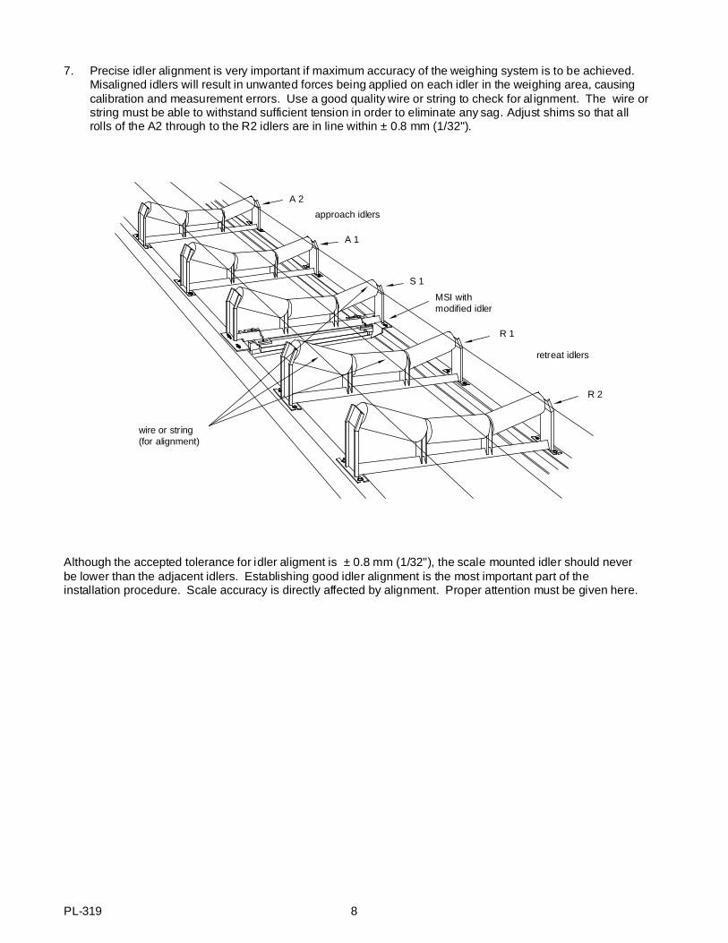
7. Precise idler alignment is very important if maximum accuracy of the weighing system is to be achieved.Misaligned idlers will result in unwanted forces being applied on each idler in the weighing area, causingcalibration and measurement errors. Use a good quality wire or string to check for al ignment. The wire orstring must be able to withstand sufficient tension in order to eliminate any sag. Adjust shims so that all rolls of the A2 through to the R2 idlers are in line within ± 0.8 mm (1/32").
Although the accepted tolerance for idler aligment is ± 0.8 mm (1/32"), the scale mounted idler should neverbe lower than the adjacent idlers. Establishing good idler alignment is the most important part of theinstallation procedure. Scale accuracy is directly affected by alignment. Proper attention must be given here.
A 1
MSI withmodified idler
S 1
wire or string (for alignment)
approach idlers
retreat idlers
R 2
A 2
R 1
PL-319 8
CALIBRATION
GENERAL
After the MSI has been properly installed, calibration of the weighing system must be done in conjunction withthe integrator. Refer to the integrator instruction manual for programming and calibration. The calibration isinitially done using the supplied test load. Material tests are recommended to achieve maximum accuracy.
TEST LOAD
The test load value for your MSI is given on the accompanying data sheet. The value is to be entered into thededicated programming parameter of the integrator, in kilograms per meter or pounds per foot.
If the actual idler spacing differs from that recorded on the design data sheet, the test load must be recalculatedas follows. Failure to do so will cause the design test load value to be in error.
test load = Total weight of all test weights kg or lb idler spacing m ft
ZERO
Perform the zero calibration as described in the Calibration section of the integrator manual.
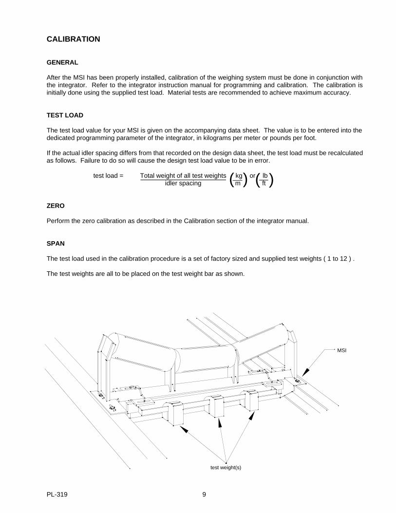
SPAN
The test load used in the calibration procedure is a set of factory sized and supplied test weights ( 1 to 12 ) .
The test weights are all to be placed on the test weight bar as shown.
( )( )
test weight(s)
MSI
PL-319 9
Perform the span calibration as described in the Calibration section of the integrator instruction manual.
After the span calibration has been completed, remove the test load and store it.
MATERIAL TEST
The MSI is guaranteed to be accurate to +/- 1/2% when installed on a conveyor in accordance with this manualand meeting the qualifications outlined in Manual PL 264 "Applications Guidlines". This guarantee is based oncalibrations performed using the test weights furnished with the scale and as referenced on the previous page.
When the existing conditions are such that the installation of the scale cannot meet the above mentionedrequirements for an approved installation it is recommended that Material tests be performed. This will enablethe user to compare the present scale results to the results of the material tests. The scale is then adjusted orfactored so that subsequent scale calibrations with test weights will agree with actual run of material.
RE-RATING
Any significant change in rate, speed and /or idler spacing from orginal design specifications should be referredto your local Milltronics office to be sure that proper design parameters are maintained.
MAINTENANCE
Due to the simplified design and the lack of moving parts, the MSI itself requires no active maintenance. Thescale weighbridge should be kept clean. Accumulation of material between the fixed support frame (static) andthe live frame (dynamic) as well as around each load cell could affect the scale accuracy. Periodically check thealignment of the stringers and idlers in the weighing area.
The conveyor on the other hand requires more attention since it is now part of the total weighing system. Whena problem arises in the conveyor, it is possible that the scale will be affected. Therefore, periodic conveyormaintenance is important to proper scale operation which should include:
» lubrication of all pulleys and idlers» proper belt tracking and training» proper belt cleaning and scraping» proper take up operation» proper material feeding and spillage control
Maintenance precautions :
» When welding near the scale do not allow current to pass through the belt scale.» Reset the shipping stops to reduce physical shock to the load cells during maintenance.» Recalibrate the scale after maintenance and prior to use.
PL-319 10

IDLER MOUNTING
The MSI is usually installed in conveyors employing conventional rigid structure idlers. Within this type of idler,construction will vary depending on the manufacture and the application. The idler depicted in the InstallationProcedure uses an angle iron spine. The following depicts alternate idler construction and tips on how theyshould be modified and installed.
TROUGHED IDLER WITH CHANNEL SPINE
idler modification
idler installation
100 mm (4")
12.7 mm(0.5")
before after
customer’s idler
gusset reinforcementif required. SeeInstallation Procedure
foot pads weldedto idler spine
idler clip
customer bolts (4 places)
PL-319 11

TROUGHED IDLER WITH PIPE SPINE
idler modification
idler installation
foot pads weldedto idler spine
welded to idler pipe( be sure idler is square toscale & conveyor frame)
gusset reinforcementif required. SeeInstallation Procedure
100 mm (4")
12.7 mm(0.5")
before after
customer’s idler
idler clip
customer bolts (4 places)
PL-319 12
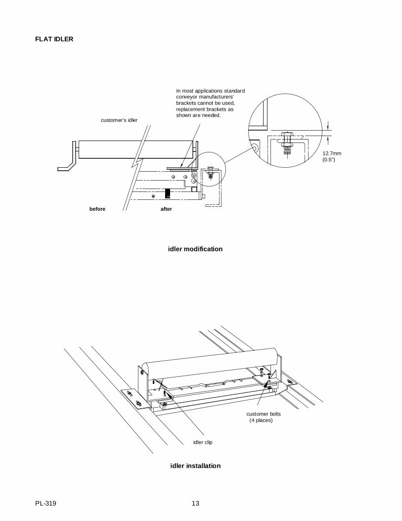
FLAT IDLER
idler modification
idler installation
12.7mm(0.5")
before after
customer’s idler
In most applications standardconveyor manufacturers’brackets cannot be used,replacement brackets asshown are needed.
idler clip
customer bolts (4 places)
PL-319 13
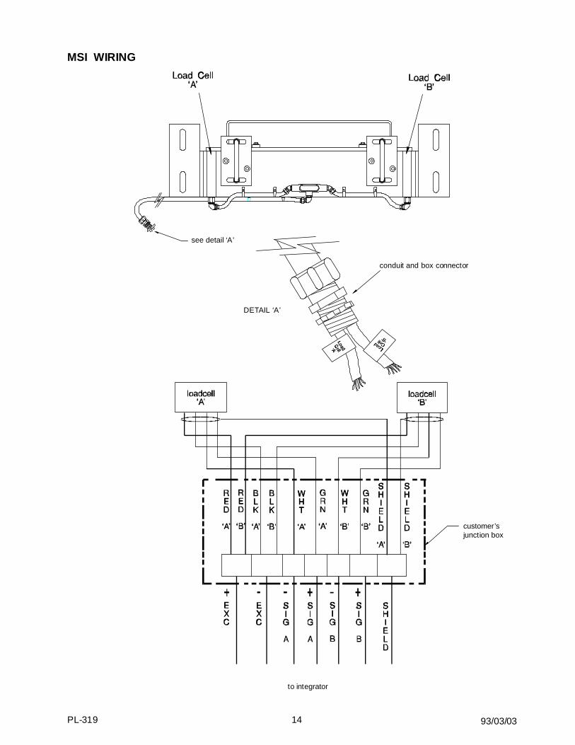
MSI WIRING
to integrator
customer’sjunction box
DETAIL ‘A’
see detail ‘A’
conduit and box connector
93/03/03PL-319 14

OUTLINE DIMENSIONS - CEMA
conveyor belt width mounting scalewidth ‘A’
minimum drop-inwidth ‘B’
‘C’ ‘D’ weight
18 " 27 " 24.5 " 9.5 " 5.5 " 82 lb20 " 29 " 26.5 " 9.5 " 5.5 " 85 lb24 " 33 " 30.5 " 9.5 " 5.5 " 90 lb30 " 39 " 36.5 " 9.5 " 5.5 " 99 lb36 " 45 " 42.5 " 9.5 " 5.5 " 107 lb42 " 51 " 48.5 " 9.5 " 5.5 " 116 lb48 " 57 " 54.5 " 12 " 8 " 162 lb54 " 63 " 60.5 " 12 " 8 " 174 lb60 " 69 " 66.5 " 12 " 8 " 185 lb72 " 81 " 78.75 " 12 " 8 " 235 lb84 " 93 " 90.75 " 12 " 8 " 261 lb96 " 105 " 102.75 " 12 " 8 " 288 lb
‘D’
178 mm
( 7")
‘A’
‘B’
‘C’
PL-319 15
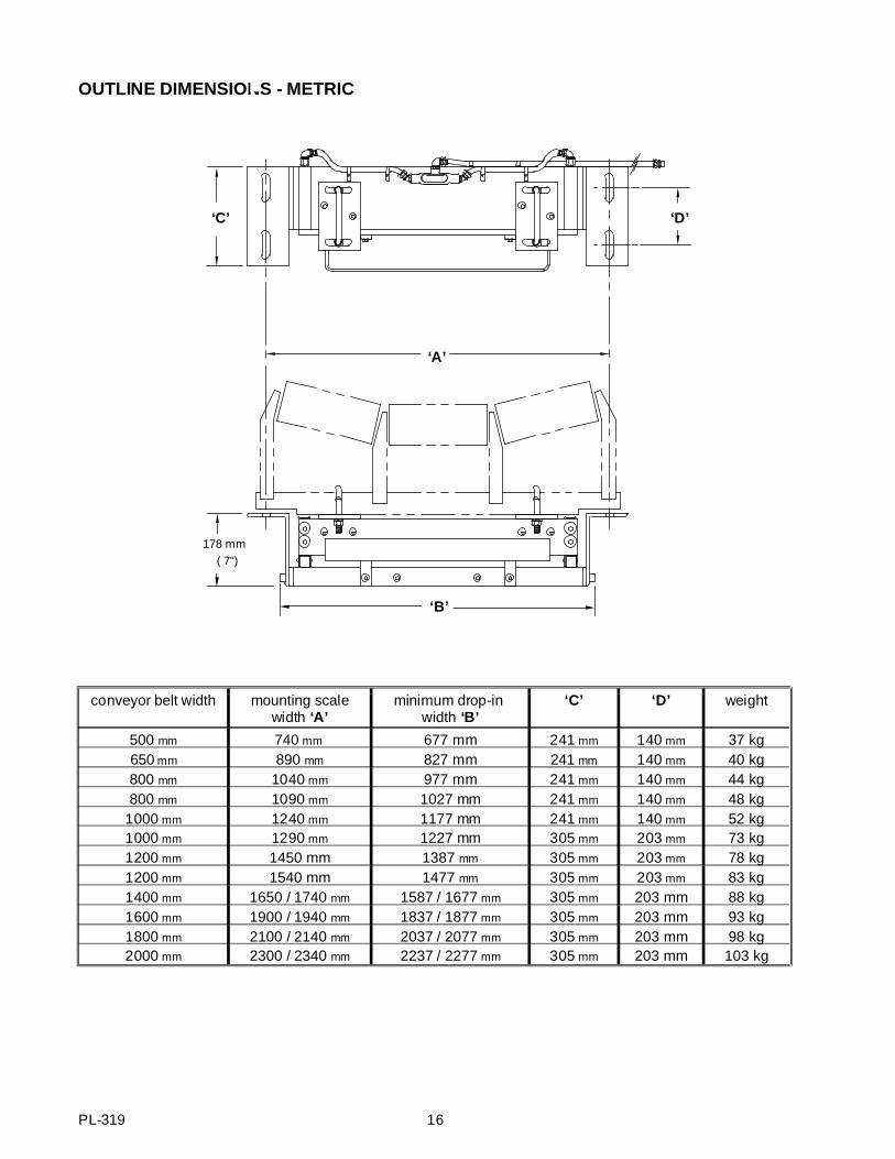
OUTLINE DIMENSIONS - METRIC
conveyor belt width mounting scalewidth ‘A’
minimum drop-in width ‘B’
‘C’ ‘D’ weight
500 mm 740 mm 677 mm 241 mm 140 mm 37 kg650 mm 890 mm 827 mm 241 mm 140 mm 40 kg800 mm 1040 mm 977 mm 241 mm 140 mm 44 kg800 mm 1090 mm 1027 mm 241 mm 140 mm 48 kg
1000 mm 1240 mm 1177 mm 241 mm 140 mm 52 kg1000 mm 1290 mm 1227 mm 305 mm 203 mm 73 kg1200 mm 1450 mm 1387 mm 305 mm 203 mm 78 kg1200 mm 1540 mm 1477 mm 305 mm 203 mm 83 kg1400 mm 1650 / 1740 mm 1587 / 1677 mm 305 mm 203 mm 88 kg1600 mm 1900 / 1940 mm 1837 / 1877 mm 305 mm 203 mm 93 kg1800 mm 2100 / 2140 mm 2037 / 2077 mm 305 mm 203 mm 98 kg2000 mm 2300 / 2340 mm 2237 / 2277 mm 305 mm 203 mm 103 kg
‘D’
178 mm ( 7")
‘A’
‘B’
‘C’
PL-319 16