Embed Size (px)
Citation preview

5/16/2018 MSGB200921 - slidepdf.com
http://slidepdf.com/reader/full/msgb200921 1/48
Document ref. MSGB200921.doc P. 1 / 48
RGK-60GENERATOR SET CONTROL UNIT
REMOTE CONTROL SOFTWARE MANUAL
LIST OF CONTENTS
Introduction...................................................................................................................................................... 2Minimum PC resources.................................................................................................................................. 2
Set-up................................................................................................................................................................ 2
Activating the PC-RGK connection ............................................................................................................... 3Direct connection via RS-232 ........................................................................................................................ 3Connection via RS-485.................................................................................................................................. 3
Connection via modem .................................................................................................................................. 3Connection via GSM modem......................................................................................................................... 3
Basic principles............................................................................................................................................... 4
Main window .................................................................................................................................................... 5
System configuration...................................................................................................................................... 6
View Menu ...................................................................................................................................................... 10Data log........................................................................................................................................................ 10 Alarms .......................................................................................................................................................... 11Events .......................................................................................................................................................... 12Graphs ......................................................................................................................................................... 13I/O Status ..................................................................................................................................................... 14
Password........................................................................................................................................................ 15
Communication menu................................................................................................................................... 16Online........................................................................................................................................................... 16Offline........................................................................................................................................................... 16Modem call................................................................................................................................................... 16Wait for incoming calls ................................................................................................................................. 17Hang up........................................................................................................................................................ 17
Parameters menu........................................................................................................................................... 18Setup............................................................................................................................................................ 18 Access to the parameters ............................................................................................................................ 19 Alarm table................................................................................................................................................... 20
Save on file .................................................................................................................................................. 20Load from file ............................................................................................................................................... 20Print.............................................................................................................................................................. 20Modem parameters...................................................................................................................................... 21
Page editor ..................................................................................................................................................... 22Types of Indicators....................................................................................................................................... 26Types of Objects .......................................................................................................................................... 35Initial page generation.................................................................................................................................. 38
APPENDIX A – Connection modes .............................................................................................................. 39Direct RS-232 connection ......................................................................................................................................... 39PC-RGK connection via RS-485 (RGK without internal RS-485 interface) ............................................................... 40PC-RGK connection via RS-485 interface (RGK with internal interface)................................................................... 41
Connection via standard modem............................................................................................................................... 42Connection via GSM modem .................................................................................................................................... 44
Appendix B – Commands with SMS messages ......................................................................................... 46
I 1 2 4
G B
0 1 0 2

5/16/2018 MSGB200921 - slidepdf.com
http://slidepdf.com/reader/full/msgb200921 2/48
Document ref. MSGB200921.doc P. 2 / 48
IntroductionWith the remote control software for the RGK unit it is possible to:
• View the status of the equipment, with the current measurements, the operating mode, engineparameters etc. on a PC in graphic form.
• View any active alarms
• View the events recorded by the equipment
• View and modify the equipment setting parameters, with the possibility to save on disk, call up and printthe settings.
• Sample certain user-defined measurements and save them on disk in different formats (MS-Access, ASCII text, MS-Excel).
• Trace graphs of the sampled measurements.
• Possibility for the user to personalise the pages according to preference, inserting indicators associatedwith the measurements, background images, wordings and control buttons.
• Change the language of the menus and of the program commands choosing between Italian, English,French, German and Spanish.
Minimum PC resources• Windows 95/98/2000 operating system
• Graphic board with minimum resolution 800x600, recommended 1024x768 or higher
• One standard, free Rs232 serial interface (COM:)
• 64Mb RAM
• Pentium or higher class processor
• CD-ROM drive for set-up
Set-upTo be able to proceed with set-up the personal computer must have the operating system already installedand working and the CD for program set-up. Also a minimum of experience with the personal computer andthe commands of the windows operating system is necessary.
The software is supplied on a CD with two different set-up procedures. Under the Setup1 directory there isthe standard set-up procedure used with Win 95 and 98 first release operating systems. Under the Setup2 directory there is a new set-up procedure, suitable for Win 98 latest release and Win 2000 operatingsystems.
Setup1:1. Close any open applications2. Insert the CD in the drive3. From the Setup1 directory, start the Setup.exe program4. Press the square button with the icon of a PC to start the set-up procedure.5. A window will be shown asking you to specify the directory in which to install the program. If you want to
change it, specify the new name in the box provided.6. Follow the instructions as they appear on the screen. If the presence of more recent files on the PC than
those being installed is indicated, keep the ones already present (answer YES or ‘keep’ to the questionwhether to keep them)7. If at the end of set-up you are asked to restart the system, carry out the procedure.
Setup2:1. Close any open applications2. Insert the CD in the drive3. From the Setup2 directory, start the Setup.exe program4. A window will be shown asking you to specify the directory in which to install the program. If you want to
change it, specify the new name in the box provided.5. If at the end of set-up you are asked to restart the system, carry out the procedure.
5/16/2018 MSGB200921 - slidepdf.com
http://slidepdf.com/reader/full/msgb200921 3/48
Document ref. MSGB200921.doc P. 3 / 48
Activating the PC-RGK connectionFor the function remote control program to be able to work, the PC and the RGK must be able to conversevia serial interface. The serial connection can be made in different ways depending on the distance betweenthe PC and the RGK and the modes required by the user, but in any case, it will be necessary to use a serialport of the PC. Therefore, the first thing to do is make sure that the PC you intend to use has an availableand free RS-232 serial interface. Serial ports are commonly marked with the code COM and usually go fromCOM1: up to COM4:, even if most PCs in commerce only have two serial ports (COM1: and COM2:) ,identifiable by the 9-pin male connector. To be able to use the program, it is firstly necessary to identify the
PC port you want to use, remembering that in some cases a serial port may already be occupied by themouse. The software will then have to be configured to use the port chosen. This may be done either duringset-up or later through the Configuration-Options-General menu (see the associated paragraph).
Direct connection via RS-232This type of connection is the simplest, and it involves the direct connection between the serial port of the PCand that of the RGK (telephone connector with RJ6/6 pin, on the back of the equipment) made through thespecific cable supplied by Lovato (code 51C2). This connection mode should be used during set-up, fine-tuning or maintenance of the RGK, but it is not suitable for a permanent connection because by nature theRS232 interface is unable to reach long distances and may be affected by the disturbances present in anindustrial environment. In the event of problems, or for further information, see Appendix A.
Connection via RS-485This type of connection allows permanent connection according to industrial standard RS-485, with thepossibility of multipoint connection of up to a maximum of 99 RGKs connected to a personal computer. Thissolution enables a reliable and permanent connection, suitable for an industrial environment and makes itpossible to reach distances in the region of 1Km.To make a connection of this type, an RS-232 / RS-485 converter for the PC plus a converter for each pieceof equipment are necessary (if they are not fitted with an internal RS-485 interface). For the connectionlayouts, refer to the wiring diagrams in appendix A at the end of this manual.
Connection via modemWhen the PC and the RGK are located at a considerable distance from one another, it is possible toestablish remote control through a pair of modems. In this case the PC Must be connected to the modem
through the cable supplied with the modem. While on the other end the RGK must be connected to themodem through the cable supplied by Lovato. This type of connection may entail some difficulty for userswho are not familiar with the use and programming of modems, as certain programming is necessarydepending on the type of modem used, the type of telephone line, etc. For further information see Appendix A.
Connection via GSM modemThe remote control software also includes the possibility of using a GSM modem connected to the RGK.This is a device which combines a modem and a cell phone, allowing data transmission also from places thatdo not have the normal telephone line. In addition to performing the normal functions of a modem, thisdevice also offers the possibility of sending SMS messages (Short Message Service) to other GSM mobilephones, making it possible to signal alarms with this innovative system. Through an extension of the SMSprovided by some operators, this also makes it possible to send e-mail messages. Both the RGK and the
remote control software have been adapted for the use of these possibilities. In this case, too, the installationof this kind of system requires a certain amount of experience with modems.
5/16/2018 MSGB200921 - slidepdf.com
http://slidepdf.com/reader/full/msgb200921 4/48
Document ref. MSGB200921.doc P. 4 / 48
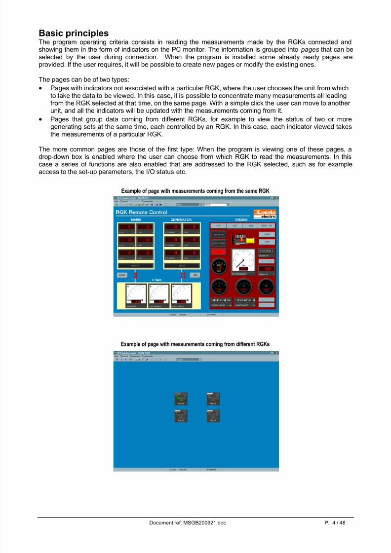
Basic principlesThe program operating criteria consists in reading the measurements made by the RGKs connected andshowing them in the form of indicators on the PC monitor. The information is grouped into pages that can beselected by the user during connection. When the program is installed some already ready pages areprovided. If the user requires, it will be possible to create new pages or modify the existing ones.
The pages can be of two types:
• Pages with indicators not associated with a particular RGK, where the user chooses the unit from which
to take the data to be viewed. In this case, it is possible to concentrate many measurements all leadingfrom the RGK selected at that time, on the same page. With a simple click the user can move to another unit, and all the indicators will be updated with the measurements coming from it.
• Pages that group data coming from different RGKs, for example to view the status of two or moregenerating sets at the same time, each controlled by an RGK. In this case, each indicator viewed takesthe measurements of a particular RGK.
The more common pages are those of the first type: When the program is viewing one of these pages, adrop-down box is enabled where the user can choose from which RGK to read the measurements. In thiscase a series of functions are also enabled that are addressed to the RGK selected, such as for exampleaccess to the set-up parameters, the I/O status etc.
Example of page with measurements coming from the same RGK
Example of page with measurements coming from different RGKs

5/16/2018 MSGB200921 - slidepdf.com
http://slidepdf.com/reader/full/msgb200921 5/48
Document ref. MSGB200921.doc P. 5 / 48
Main windowThe main window of the program contains all the menus and toolbars that allow access to the variousfunctions available. Some of these functions which may alter the software configuration are protected by apassword, and are therefore disabled when the program is started. The figure below shows the main windowwith the more frequently used controls.
Fig 1.1 – Main window
The page shown above, called MAIN is one of the ready pages provided with the program. The indicators onthis page are not associated, therefore the measures viewed refer each time to the unit selected in the box
for choosing the RGK at the top right.It groups together many of the most important measurements provided by the RGK, namely the following:
A) Mains, phase-neutral and between line voltages.B) Generator, phase-neutral and between line voltages.C) Status of mains / generator contactorsD) Choosing and setting the RGK operating mode (OFF-MAN-AUT-TEST)E) Engine started indicator F) Alarms on indicator G) RGK alarm indicator H) Battery voltageI) Status of analogue fuel – temperature – pressure sensors (if available)J) Engine operating hours meter and Hours to go before scheduled maintenance interval
K) Pushbuttons to reset the above metersL) Attempted starts counter M) Percentage of successful attempted starts.
Box for choosingthe page
Box for choosingthe unit
Toolbar with the mostcommon functionsand commands
B
C
D
E
F
G
H
C
I
J K
L
M
Number of activealarms
Page updatingtime
Communication status:ONLINEOFFLINE

5/16/2018 MSGB200921 - slidepdf.com
http://slidepdf.com/reader/full/msgb200921 6/48
Document ref. MSGB200921.doc P. 6 / 48
System configurationTo be able to access the configuration, it is necessary to enter the password which after program set-up isby default, LOVATO. Click on the password menu, type Lovato and then confirm with OK.Then select the Configuration-Options menu or click on the symbol on the toolbar.
System configuration is a highly important phase for the definition of how the software works.So, before explaining the various program functions we are going to dwell a while on the configurationwindow, listing the function of all the settings. The more detailed explanation about the purpose of each
setting will be dealt with more extensively in the chapters that follow.
Fig. 2.1 - Configuration-Options-General This window groups the configurations of a general nature. It is possible to call this window at any time andact on the configuration.
Choice of default coloursof pages andindicators
Choice of programmelanguage.
PC serial portsettings
Choice of direct/modemconnection.If a modemconnected to thePC is used,select the box
Any initialisation
command to besent to themodem.Normally notnecessary

5/16/2018 MSGB200921 - slidepdf.com
http://slidepdf.com/reader/full/msgb200921 7/48
Document ref. MSGB200921.doc P. 7 / 48
Fig. 2.2 - Configuration-Options-UnitsThrough this window it is possible to define how many RGK units are connected to the PC. Clearly, if we usea direct connection via RS-232, it will be possible to connect to only one unit. Conversely, if an RS-485network is used, which allows a multipoint connection, it will be necessary to specify how many units are tobe controlled by the PC. A free name can be defined for each unit (for example GROUP1), which will beused every time that particular RGK is to be selected.The list of the RGKs defined in this configuration page will then be viewed on the main page, in the unitchoice box.This window is enabled only in case of direct connection, that is when the modem is NOT used. See nextchapter for more details on the operating mode in case of modem connection.
Number of RGKunits connected.
Adds a unit Eliminates a unit.Warning:If data log has beenenabled, theelimination of a unitfrom the networkinvolves the loss of any data stored. SeeData Log chapter .
Unit currentlyselected.Corresponds to theserial addressprogrammed on the
RGK.
Free nameassociated with thisunit.
Enables conversationwith the chosen unit.If deactivated the unitis ignored (helpful for example when theunit is momentarilyout of service).
5/16/2018 MSGB200921 - slidepdf.com
http://slidepdf.com/reader/full/msgb200921 8/48
Document ref. MSGB200921.doc P. 8 / 48
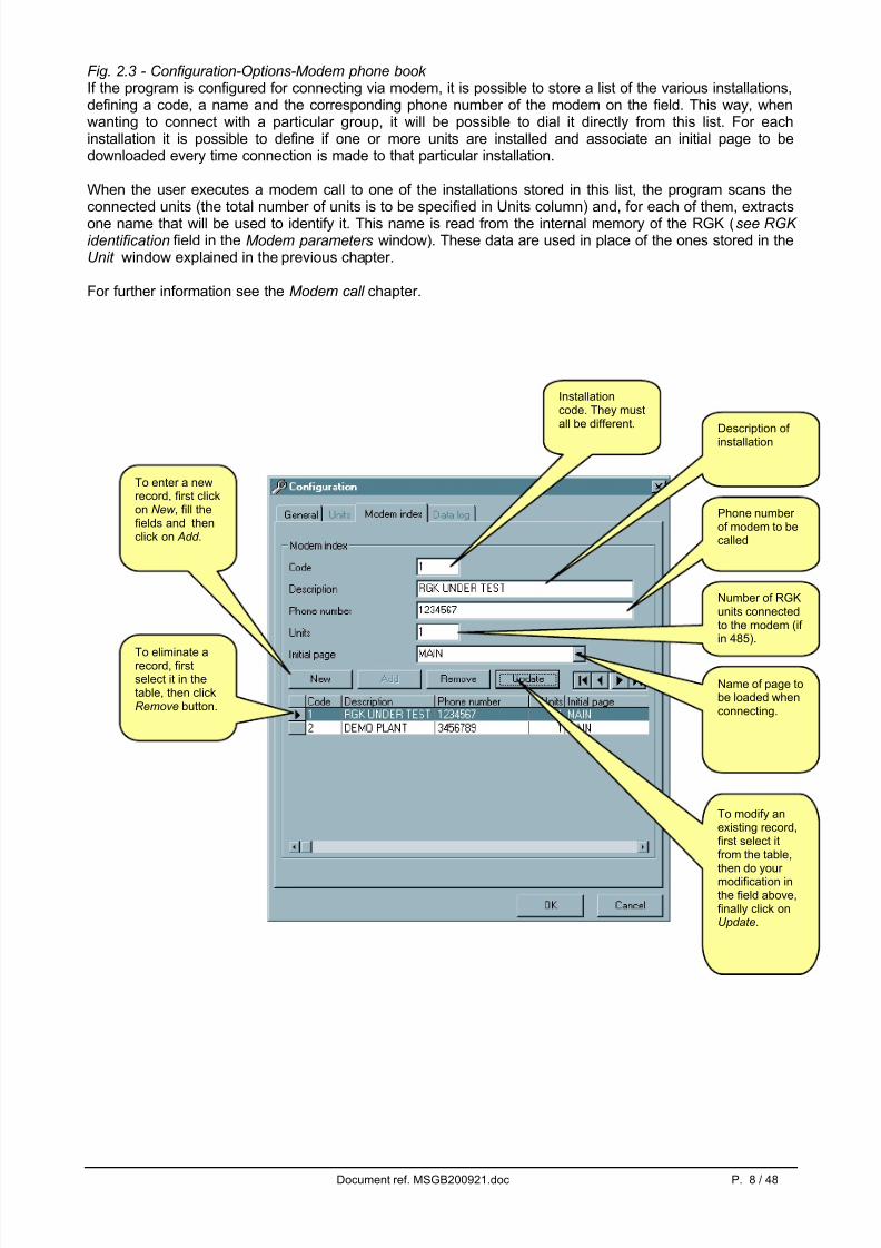
Fig. 2.3 - Configuration-Options-Modem phone book If the program is configured for connecting via modem, it is possible to store a list of the various installations,defining a code, a name and the corresponding phone number of the modem on the field. This way, whenwanting to connect with a particular group, it will be possible to dial it directly from this list. For eachinstallation it is possible to define if one or more units are installed and associate an initial page to bedownloaded every time connection is made to that particular installation.
When the user executes a modem call to one of the installations stored in this list, the program scans theconnected units (the total number of units is to be specified in Units column) and, for each of them, extractsone name that will be used to identify it. This name is read from the internal memory of the RGK (see RGK identification field in the Modem parameters window). These data are used in place of the ones stored in theUnit window explained in the previous chapter.
For further information see the Modem call chapter .
Installationcode. They mustall be different. Description of
installation
Phone number of modem to becalled
Number of RGKunits connectedto the modem (if in 485).
Name of page tobe loaded whenconnecting.
To enter a newrecord, first clickon New , fill thefields and thenclick on Add .
To eliminate arecord, firstselect it in thetable, then clickRemove button.
To modify anexisting record,first select itfrom the table,
then do your modification inthe field above,finally click onUpdate.
5/16/2018 MSGB200921 - slidepdf.com
http://slidepdf.com/reader/full/msgb200921 9/48
Document ref. MSGB200921.doc P. 9 / 48
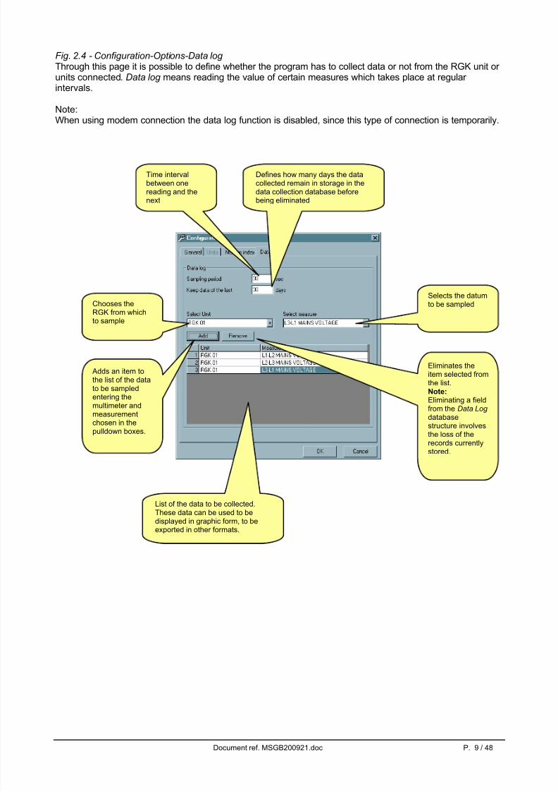
Fig. 2.4 - Configuration-Options-Data log Through this page it is possible to define whether the program has to collect data or not from the RGK unit or units connected. Data log means reading the value of certain measures which takes place at regular intervals.
Note:When using modem connection the data log function is disabled, since this type of connection is temporarily.
Time intervalbetween onereading and thenext
Chooses theRGK from whichto sample
Selects the datumto be sampled
Adds an item tothe list of the datato be sampledentering themultimeter and
measurementchosen in thepulldown boxes.
Eliminates theitem selected fromthe list.Note:Eliminating a fieldfrom the Data Log databasestructure involvesthe loss of therecords currentlystored.
List of the data to be collected.These data can be used to bedisplayed in graphic form, to beexported in other formats.
Defines how many days the datacollected remain in storage in thedata collection database beforebeing eliminated

5/16/2018 MSGB200921 - slidepdf.com
http://slidepdf.com/reader/full/msgb200921 10/48
Document ref. MSGB200921.doc P. 10 / 48
View Menu
Data logThe variables defined in the Data log configuration page (Fig. 2.4) are sampled cyclically by the program,with an acquisition speed defined by the user with the Sampling period setting, and then saved in thedatabase with the date and time.
When defining the Sampling period , pay attention to the amount of space available on the disk. For example,setting a sampling period of 5 seconds, as many as 17280 records a day would be saved, each with thedate, time and value of every variable included in the Data log list.In order to limit the occupation of storage of the files on the disk it is possible to automatically eliminate fromthe database samples older than a required number of days. Setting for example Keep data of last … days at 7, the samples of the last week will be kept in the database.
The Data log database resides in the rgk.mdb file, in the program set-up directory. It is a normal Ms-Accessfile, that can also be read from other applications. The Data log is stored in the DataLog table.
The data collected can be displayed in table form with the View-Data log menu, or clicking the correspondingicon on the toolbar.
Fig. 3.1 – View-Data log
Date and time of sampling
Number of records chosen
Values of variables sampled
Period chosen for viewing. Ittakes the values included in acertain interval of time fromthe database.
Opens the window with whichit is possible to specify theinterval of time to be chosen
Views all therecords of thedatabase
Allows the dataselected to beexported in ASCIIor Excel textformat files
Deletes thedata selectedfrom thedatabase.
5/16/2018 MSGB200921 - slidepdf.com
http://slidepdf.com/reader/full/msgb200921 11/48
Document ref. MSGB200921.doc P. 11 / 48
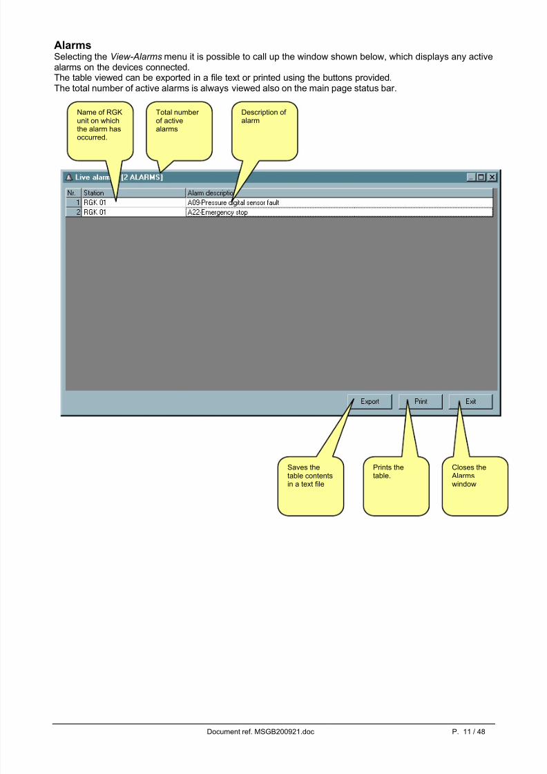
AlarmsSelecting the View-Alarms menu it is possible to call up the window shown below, which displays any activealarms on the devices connected.The table viewed can be exported in a file text or printed using the buttons provided.The total number of active alarms is always viewed also on the main page status bar.
Saves thetable contentsin a text file
Prints thetable.
Closes the Alarmswindow
Name of RGKunit on whichthe alarm has
occurred.
Total number of activealarms
Description of alarm

5/16/2018 MSGB200921 - slidepdf.com
http://slidepdf.com/reader/full/msgb200921 12/48
Document ref. MSGB200921.doc P. 12 / 48
EventsWith the View-Events menu it is possible to view the list of events recorded by the RGK selected, in thesame form in which they would be viewed from the front panel of the apparatus.
Saves thetable contentsin a text file
Prints thetable.
Closes theEventswindow
Name of the unit to whichthe events refer
5/16/2018 MSGB200921 - slidepdf.com
http://slidepdf.com/reader/full/msgb200921 13/48
Document ref. MSGB200921.doc P. 13 / 48
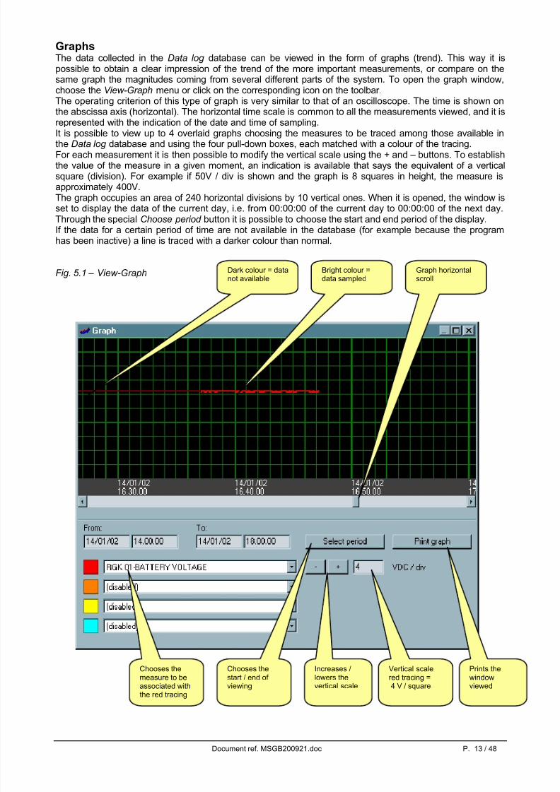
GraphsThe data collected in the Data log database can be viewed in the form of graphs (trend). This way it ispossible to obtain a clear impression of the trend of the more important measurements, or compare on thesame graph the magnitudes coming from several different parts of the system. To open the graph window,choose the View-Graph menu or click on the corresponding icon on the toolbar.The operating criterion of this type of graph is very similar to that of an oscilloscope. The time is shown onthe abscissa axis (horizontal). The horizontal time scale is common to all the measurements viewed, and it isrepresented with the indication of the date and time of sampling.
It is possible to view up to 4 overlaid graphs choosing the measures to be traced among those available inthe Data log database and using the four pull-down boxes, each matched with a colour of the tracing.For each measurement it is then possible to modify the vertical scale using the + and – buttons. To establishthe value of the measure in a given moment, an indication is available that says the equivalent of a verticalsquare (division). For example if 50V / div is shown and the graph is 8 squares in height, the measure isapproximately 400V.The graph occupies an area of 240 horizontal divisions by 10 vertical ones. When it is opened, the window isset to display the data of the current day, i.e. from 00:00:00 of the current day to 00:00:00 of the next day.Through the special Choose period button it is possible to choose the start and end period of the display.If the data for a certain period of time are not available in the database (for example because the programhas been inactive) a line is traced with a darker colour than normal.
Fig. 5.1 – View-GraphGraph horizontal
scroll
Bright colour =
data sampled
Dark colour = data
not available
Vertical scalered tracing =4 V / square
Increases /lowers thevertical scale
Chooses themeasure to beassociated withthe red tracing
Chooses thestart / end of viewing
Prints thewindowviewed

5/16/2018 MSGB200921 - slidepdf.com
http://slidepdf.com/reader/full/msgb200921 14/48
Document ref. MSGB200921.doc P. 14 / 48
I/O StatusThe input/output status of the RGK can be viewed through the View-I/O Status menu which calls up thewindow illustrated. This shows the digital inputs (i.e. the ON-OFF signals leading from the generator set thatare read by the board) and the outputs (i.e. the internal board relays, for controlling the generator set). Sincethe RGK makes it possible to associate each terminal with a user-selectable function, the present Input /Output functions are read from the device the moment the window is opened. The active status is shown inred, while the rest condition is shown in the neutral background colour.

5/16/2018 MSGB200921 - slidepdf.com
http://slidepdf.com/reader/full/msgb200921 15/48
Document ref. MSGB200921.doc P. 15 / 48
PasswordWhen the program is started some of the functions are deactivated. Using the Password menu it is possibleto enter the password that allows access to all the functions, i.e.:
• Modifying the settings of the remote control
• Modifying the password
• Eliminating records from the Data log database
• Accessing the page editor
• Modifying the set-up parameters of the RGKs connected
Fig. 8.1 – Password
At the time of first set-up the password is LOVATO. The user can then record a new personalised password,clicking on the New password button and entering the newly chosen password twice consecutively.
Fig. 8.2 – New password

5/16/2018 MSGB200921 - slidepdf.com
http://slidepdf.com/reader/full/msgb200921 16/48
Document ref. MSGB200921.doc P. 16 / 48
Communication menu
OnlineWith the Communication-Online menu it is possible to resume the serial connection when it has beenpaused by the operator through the Offline command. When choosing to reactivate serial communication,the program runs a scan of all the RGKs configured in the network to check their status.
OfflineWith Communication-Offline the user has the possibility to temporarily suspend serial communicationbetween the PC and the RGKs. When the program is in this mode, the indicators are shown in the restcondition and Data log is suspended.This command is to be used for example when wanting to temporarily disconnect the RS232 communicationcable, or if wanting to cut off the supply to the devices connected. The Offline system status is shown by apanel on the main window status bar (at the bottom of the screen).The system passes automatically to the offline mode when the Options or Page editor configuration isaccessed.
Modem callThis option is available only if the program has been configured for connecting via modem (see theConfiguration-Options-General window).This choice brings up a window in which it is possible to make a call via modem from the PC to a station withan RGK fitted with modem. Once the window illustrated has been opened, from the pull-down box choosethe name of the installation with which you want to be connected. The names entered in the Modem phonebook during configuration will be displayed. Once the choice has been made, the corresponding phonenumber appears in the box below. Click the Dial button to start the connection procedure.
At this point the program will instruct the modem to make the call. While waiting, the sliding blue bar of themaximum time allowed for making the connection will be seen (1 minute). The modem called will take theline and exchange the usual handshaking messages with the calling modem. At the end of this procedure, if
everything has been carried out correctly, the PC monitor will show a window informing the user thatconnection has taken place and the program will switch automatically to the Online mode. If any errorsoccur, carefully check the connections and if necessary follow the Guide to solving connection problems given in appendix B of this manual. Normally connection is not critical since very common and absolutelystandard procedures are used. With the Break button it is possible to block the calling procedure, while Hang up ends a communication already in progress.

5/16/2018 MSGB200921 - slidepdf.com
http://slidepdf.com/reader/full/msgb200921 17/48
Document ref. MSGB200921.doc P. 17 / 48
Wait for incoming callsChoosing this option the program sets to the call standby mode, in which the PC answers incoming calls onthe modem. In this case, it is presumed that there are one or more RGKs on the field programmed for making an autonomous call to the PC in the case of alarm or at periodical intervals (on this subject see theModem parameters paragraph). When an RGK calls, the PC connects and records the date, time andidentity of the caller in a text file that can be viewed using the View calls log button. If the user is in front of the PC at the time of the call, there will be the possibility to remain connected and check the nature of theproblems. Conversely, if the PC station is unattended, after a few seconds the PC will close the connection
automatically, recording in the file that the call has not been controlled by the user. Later the user may checkhow many and which calls were received during his absence and possibly connect manually with the RGKunder alarm. In fact these calls will be highlighted in blue and they will have the User Ack set at No.Selecting a recorded call, it is possible to change its status to ‘Controlled Call’ through the Checked button or eliminate it definitively from the list through the Delete button.The list of calls is stored on disk in the ASCII text file Modemcal.txt , located in the same directory as theRGK.exe application.
Hang upThis command interrupts a modem connection, closing the telephone line. It is the equivalent of hanging upthe handset in an ordinary phone call. It is carried out automatically every time you exit the program.

5/16/2018 MSGB200921 - slidepdf.com
http://slidepdf.com/reader/full/msgb200921 18/48
Document ref. MSGB200921.doc P. 18 / 48
Parameters menu
Setup Access to the RGK set-up parameters is gained through the Parameters menu. Clicking Parameters-Setup views the window shown below, with the tree that represents the structure of the menu of the device.
The menu structure gathers all the information concerning the parameters, for example code, description,minimum, maximum, default values etc. These pieces of information are stored in special files on the disk.When the software is installed, the files that refer to the currently used parameter structure are copied. Thisnormally allows immediate access to parameter setting.
If however changes are made to the software inside the device which involve modification of the structure of the parameters (for example a parameter is added or the setting range of an existing parameter is modified),once connected to a board with new revision, the program will automatically indicate the need to create thefile with the new structure, downloading it from the device.
Answering Yes the downloading procedure will be started. At the end of this operation, which may take a fewminutes, it will be possible to access the parameters of the new board. The downloaded data will be stored inthe special file and afterwards it will no longer be necessary to repeat this operation.

5/16/2018 MSGB200921 - slidepdf.com
http://slidepdf.com/reader/full/msgb200921 19/48
Document ref. MSGB200921.doc P. 19 / 48
Access to the parametersTo view one of the Set-up menus, double click on the corresponding item of the tree in the Set-UpParameters window.
The window below is shown which views the values set currently in the RGK.
It is possible to carry out modifications and transmit them immediately to the device through the Transmit button.
If the parameters are altered on the screen without being transmitted to the RGK, when the window isclosed a message will be shown asking whether to lose the changes or leave the possibility of transmittingthem to the device.
Description of menuselected
Parameter code
Parameter description
Double click to enter anew value with thenumerical keyboard
Drag with the mouseto set the value
Transmits and storesin the device only thismenu
Resets the factoryvalues for this menu
The yellow boxes indicatethe parameters that differ from the default values
Re-reads the valuesfrom the board andviews them

5/16/2018 MSGB200921 - slidepdf.com
http://slidepdf.com/reader/full/msgb200921 20/48
Document ref. MSGB200921.doc P. 20 / 48
Alarm tableUnlike all the others, the menu with the alarm table is presented with boxes through which it is possible toactivate or deactivate the single properties, in the same way as can be done acting directly on the RGK frontpanel.
Save on fileThe values of the set-up parameters can be saved on the PC disk in an ASCII text file, in order to be able toreload them in another device in an extremely convenient and quick manner. When this command isperformed the values of all the menus are saved in the file. This function is useful when needing to programa series of devices with the same settings, or when wanting to keep a file of the original settings of a board.To save the parameters on disk, choose the Setup-Save on file menu from the Setup Parameters windowand enter the required name. The extension associated with this type of file is .PAR.
Load from fileTo carry out the reverse operation, i.e. transfer a file from the PC to the RGK, use the Setup-Load from file menu. In this case the parameters are read from the file and transmitted and stored in the RGK. During thisoperation a re-reading cycle is performed of the parameters that have just been transmitted to check that theoperation has been performed correctly.
PrintIt is also possible to obtain a printout of the settings which can be useful to file together with the systemdocuments, using the Setup-Print menu.
Transmits and storesthis menu only in thedevice
Re-reads the propertiesof the alarms from theboard and displays them
Resets the factoryvalues for this menu
Alarm propertiesBoxes for enabling-disabling properties
Slide the bar to accessthe following alarms
Alarm code anddescription
5/16/2018 MSGB200921 - slidepdf.com
http://slidepdf.com/reader/full/msgb200921 21/48
Document ref. MSGB200921.doc P. 21 / 48
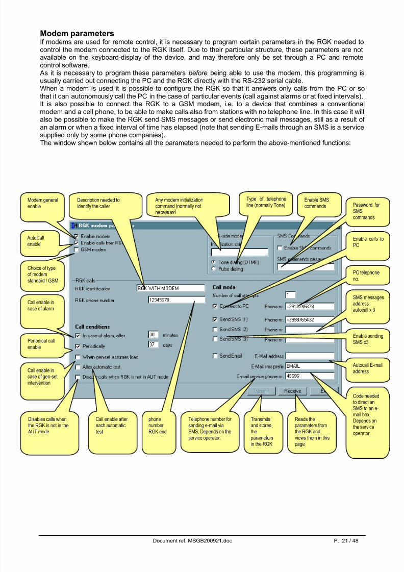
Modem parametersIf modems are used for remote control, it is necessary to program certain parameters in the RGK needed tocontrol the modem connected to the RGK itself. Due to their particular structure, these parameters are notavailable on the keyboard-display of the device, and may therefore only be set through a PC and remotecontrol software. As it is necessary to program these parameters before being able to use the modem, this programming isusually carried out connecting the PC and the RGK directly with the RS-232 serial cable.When a modem is used it is possible to configure the RGK so that it answers only calls from the PC or so
that it can autonomously call the PC in the case of particular events (call against alarms or at fixed intervals).It is also possible to connect the RGK to a GSM modem, i.e. to a device that combines a conventionalmodem and a cell phone, to be able to make calls also from stations with no telephone line. In this case it willalso be possible to make the RGK send SMS messages or send electronic mail messages, still as a result of an alarm or when a fixed interval of time has elapsed (note that sending E-mails through an SMS is a servicesupplied only by some phone companies).The window shown below contains all the parameters needed to perform the above-mentioned functions:
Modem generalenable
AutoCallenable
Choice of typeof modemstandard / GSM
Description needed toidentify the caller
Any modem initializationcommand (normally notnecessar
Type of telephoneline (normally Tone)
phonenumber RGK end
Call enable incase of alarm
Periodical callenable
Call enable incase of gen-setintervention
Call enable after each automatictest
Disables calls whenthe RGK is not in the
AUT mode
Enable calls toPC
Enable sendingSMS x3
Telephone number for sending e-mail viaSMS. Depends on theservice operator.
Code neededto direct anSMS to an e-mail box.Depends onthe serviceoperator.
Autocall E-mailaddress
SMS messagesaddressautocall x 3
PC telephoneno.
Enable SMScommands Password for
SMScommands
Transmitsand storestheparametersin the RGK
Reads theparameters fromthe RGK andviews them in thispage

5/16/2018 MSGB200921 - slidepdf.com
http://slidepdf.com/reader/full/msgb200921 22/48
Document ref. MSGB200921.doc P. 22 / 48
Page editor The page editor is the part of the remote control software that allows the user to make personalised screens,inserting animated indicators and fixed objects to view the information from the RGK in the most appropriateform for representing the status of the generator set. This subject, which would be an integrating part of theconfiguration, has been left as the last subject of this manual as it is intended for users who are highlyfamiliar with the use of the PC and with the problems involved in serial communication.
To access the page editor, enter the password and call the Configuration-Page editor menu.
It should be noted that during the construction of pages and when modifying the Options window, theprogram sets to the Offline mode, i.e. communication with the RGK is interrupted.
As soon as it is activated, the page editor shows an empty page. Through the File menu it is possible tocarry out the usual load, save and create new page operations, It should be noted that the pages handled bythe program are all located in a folder (called …\PAGES\ENG when the program is set in English) and thatthe page loading and saving operations are only carried out in that folder. For this reason the loading andsaving windows are not the usual Windows ones but in a simpler form.
The paragraphs that follow describe the page editor functions and guide the user in the creation of a trialpage.

5/16/2018 MSGB200921 - slidepdf.com
http://slidepdf.com/reader/full/msgb200921 23/48
Document ref. MSGB200921.doc P. 23 / 48
Step 1The first operation the user has to do is to define some general properties of the new page, such as theheader, background color and any background image. To do this, click on the Page-Properties menu andcall the window shown below:
Fig. 10.1 – Page-Properties
Step 2 At this point, let us suppose that in our page we want to insert an indicator of the dial gauge type showing the
mains L1 phase voltage. We choose the Indicator-Add menu or we click with the right mouse button on anempty point of the page and choose Add indicator from the pop-up menu. The window below will be shown:
Fig. 10.2 – Indicator-Add-Indicator type
If necessary, specify here the name of anygraphic file that will act as background for the page.The sizes of the original file must becompatible with those of the page.
Allows the choice of anybackground graphic file.BMP, GIF and JPGformats are supported.
Text that willappear on theheader bar
Page backgroundcolour.
Chooses thebackground colour
Choose one of theindicatorsavailable
Click this button toenter a newindicator of thetype required.

5/16/2018 MSGB200921 - slidepdf.com
http://slidepdf.com/reader/full/msgb200921 24/48
Document ref. MSGB200921.doc P. 24 / 48
We choose the button with the dial indicator and then click on the Insert new indicator button. At this point,the required indicator will appear on our page, with the standard position and dimensions. At the same timethe window proposes the base indicator settings:
Fig. 10.3 – Indicator -Properties
The window of Fig. 10.3 is shared by all the types of indicators. When specifying the device from which totake the measurement, bear in mind that:
• If an RGK is selected from the Select unit box among those defined during configuration, the
measurement shown by the indicator will always be taken from the same RGK. This solution should beadopted when wanting to insert measurements from different RGKs in the same page (see the Basic principles chapter).
• If the Select unit box is left on the Default unit setting, the indicator will show the measurement comingfrom the RGK selected at that moment in the main window (see Fig. 1.1). Making a page with all theindicators not associated with a particular RGK, this page will be able to show the measurements fromthe RGK selected each time.
We set the position and dimensions of our dial indicator, then we specify that the measurement is to betaken from the default RGK and lastly we choose the measurement we are interested in among the possibleones, which in our example is Mains voltage L1.
Indicator position.
The coordinates 0,0represent the pagetop left corner. Theobjects can also bemoved using theMove tool on thetoolbar anddragging them withthe mouse
Indicator dimensions. Some
indicators havefixed proportions,in this case thedimensions arechanged with thewidth parameter
Definition of thesize to be viewed.Choose fromwhich RGK andwhichmeasurement tobe associated withthe indicator thathas just beeninserted.
Warning!Not all theIndicator-sizecombinations arepossible. If thesize is notcompatible with
the indicator, it willbe notified with amessage.

5/16/2018 MSGB200921 - slidepdf.com
http://slidepdf.com/reader/full/msgb200921 25/48
Document ref. MSGB200921.doc P. 25 / 48
At this point we can move to the Options page of the Indicator window and complete some general options of the Gauge indicator. These options vary depending on the type of indicator chosen. In our case, for instance,we disable the Use default description box and we complete a personalised description to be shown on thedial indicator.
Fig. 10.4 – Indicator-Options (for Gauge 1 type indicator)
Clicking on OK the settings are applied to the dial indicator and the window is closed.
Following the same procedure it is possible to add other indicators to our page.
If we want to modify the settings of an already entered indicator, click on it to select (the indicator ishighlighted by a frame) and then use the Indicator-Modify menu or use the mouse right button to call theModify pop-up menu.In the same way, after selecting an indicator it can be eliminated using Delete.
Step 3 At this point we have made a very simple page which can however be loaded and displayed. Then we savethrough the File-Save As menu and we use the name MYPAGE. This command will create an ASCII filecalled MYPAGE.PGD located in the …\PAGES\ENG directory together with other pages. For anyoneconcerned, the contents of the file can be analysed and if necessary modified with a normal text editor.
Step 4We close the page editor with the File-Exit page editor menu. The program loads the main page again (Fig.1.1) or the page with the RGK stations (in this case choose one of the stations to open the main page). Thistime the pull-down box for choosing the pages (Fig. 1.1) will also contain our MYPAGE page. Choosing it,the page will be loaded and the indicator will show the required equivalent voltage.
At this point, we have concluded the minimum indispensable sequence for making a personalised page. Inorder to allow the user to exploit the potential of the program we are now going to describe thecharacteristics and options of all the indicators available.
Chooses whether
to show thestandarddescription or apersonaliseddescription of themeasurement onthe indicator
Text of personaliseddescription
Chooses whether the full scale valueof the indicator isadaptedautomatically tothe RGK setting or
whether to specifya personalised fullscale value.
Space for specifying anypersonalised fullscale value

5/16/2018 MSGB200921 - slidepdf.com
http://slidepdf.com/reader/full/msgb200921 26/48
Document ref. MSGB200921.doc P. 26 / 48
Types of Indicators
Label indicator The Label indicator shows a measurement leading from the RGK in numerical form.
Fig. 10.5 – Indicator-Options (for Label type indicator)
Description. It can be thedefault one or thepersonalised one of themeasurement.It is possible not to display it.
Numerical valueof themeasurement
Unit of measurement. It ispossible not todisplay it. Itchanges scaleautomaticallydepending on thevalue displayed(e.g. W, kW, MW)

5/16/2018 MSGB200921 - slidepdf.com
http://slidepdf.com/reader/full/msgb200921 27/48
Document ref. MSGB200921.doc P. 27 / 48
Gauge 1 Indicator
Fig. 10.6 – Indicator-Options (for Gauge 1 type indicator)
Unit of measurement.
Scale. It can bethe maximum oneof the RGK (seefig. 2.2) or personalised
Numerical valueof themeasurementDescription. It can be the
default one or thepersonalised one of themeasurement..

5/16/2018 MSGB200921 - slidepdf.com
http://slidepdf.com/reader/full/msgb200921 28/48
Document ref. MSGB200921.doc P. 28 / 48
Gauge 2 indicator
Fig. 10.7 – Indicator-Options (for gauge 2 type indicator)
It is possible touse the defaultscale or
personalise theminimum and themaximum

5/16/2018 MSGB200921 - slidepdf.com
http://slidepdf.com/reader/full/msgb200921 29/48
Document ref. MSGB200921.doc P. 29 / 48
7-segment Indicator This works in the same way as the Label type indicator, but the value is shown with 7 LED segments.
Fig. 10.8 – Indicator-Options (for 7-segment type indicator)
The unit of measurement
changes automaticallydepending on the valuedisplayed (e.g. W, kW,MW)
3 digit display with sevensegments

5/16/2018 MSGB200921 - slidepdf.com
http://slidepdf.com/reader/full/msgb200921 30/48
Document ref. MSGB200921.doc P. 30 / 48
Bar graph indicator
Fig. 10.9 – Indicator-Options (for bar graph type indicator)
The full scale valuecorresponds to themaximum value foreseen in
the RGK or it can bespecified manually
Numerical value
Unit of measurement

5/16/2018 MSGB200921 - slidepdf.com
http://slidepdf.com/reader/full/msgb200921 31/48
Document ref. MSGB200921.doc P. 31 / 48
Meter indicator
Fig. 10.10 – Indicator-Options (for meter type indicator)
Meter value
The digits after thedecimal point are on awhite background
Unit of measurement
Number of meter digits.It must equal or behigher than those of the measurement tobe shown

5/16/2018 MSGB200921 - slidepdf.com
http://slidepdf.com/reader/full/msgb200921 32/48
Document ref. MSGB200921.doc P. 32 / 48
On-Off indicator The on-off indicator serves for displaying a digital status leading from the RGK. It may be of two differentkinds:
• Normal: A rectangle with a description that changes the color of the background depending on thestatus of the variable. The color for OFF and the one for ON can be chosen freely.
• Graphic: Two graphic figures read from bitmap files of the same size. The first is displayed when thestatus is off and the second when it is on.
Fig. 10.11 – Indicator-Options (for on-off type indicator)
Chooses the colour for on (normalindicator
Chooses the colour for off (normalindicator
Defines whether theindicator has to havea 3D border aroundthe coloured part or not.
Chooses the graphicindicator type
Chooses the filename for on.The file must be in thesame directory as thepage
Chooses the filename for off.

5/16/2018 MSGB200921 - slidepdf.com
http://slidepdf.com/reader/full/msgb200921 33/48
Document ref. MSGB200921.doc P. 33 / 48
Circular indicator This type of indicator is devoted to displaying the parameters of the engine, in particular of the followingmeasurements:
• Battery voltage
• Fuel level
• Oil pressure
• Water temperature
Fig. 10.12 – Indicator-Options (for circular indicator)

5/16/2018 MSGB200921 - slidepdf.com
http://slidepdf.com/reader/full/msgb200921 34/48
Document ref. MSGB200921.doc P. 34 / 48
Unit status indicator This indicator differs from the previous ones because it is not associated with a particular measurement, butwith a whole unit, i.e. with an RGK among those connected to the PC. It is used when there are more thanone RGKs connected at the same time in the RS-485 network. This indicator groups together all the maininformation, described in the figure below:
Examples of indication:
Unit under alarm, RESET mode, engine stopped, voltages not present, contactors open.
No alarms, RESET mode, Engine stopped, Mains voltage present, mains contactor closed.
No alarms, MAN mode, Engine stopped, Mains voltage present, mains contactor closed.
Engine status:
RUN = runningSTOP = sto ed
Operating mode:may be OFF, MAN,
AUT, TEST.
MV = Mains VoltageMains voltage status.Green = Voltage OKGrey = beyond limits
GV = Generator VoltageGenerator voltage statusGreen = Voltage OKGrey = beyond limits
Network contactor statusGreen = Closed
Grey = Open
Generator contactor
statusGreen = ClosedGrey = Open
Code for identifyingthe RGK unit
Background colour:Red = alarmNeutral = OK

5/16/2018 MSGB200921 - slidepdf.com
http://slidepdf.com/reader/full/msgb200921 35/48
Document ref. MSGB200921.doc P. 35 / 48
Types of ObjectsBesides the indicators, other objects can be inserted in the page, some of which are fixed (for example fixedwordings, lines, images, etc.) and others with an active function (for example control buttons). These objectsare inserted and handled in a way very much like the one described previously for the indicators. Throughthe Object-Add menu it is possible to open the window that allows you to choose the type of object andspecify its properties.
Fig. 11.1 – Object-Add
The types of objects available are the following:
• Fixed text Fixed wording with variable color and dimensions
• Rectangle (line) Coloured rectangle. Lines can be obtained changing the height and width.
• Picture Rectangle containing a graphic file
• 3D panel Fixed wording on a 3D panel.
• Control button Button with which determinate actions can be associated
Like the indicators, also the objects have different properties depending on the type of object. In the followingpages we are going to explain the function of these properties.

5/16/2018 MSGB200921 - slidepdf.com
http://slidepdf.com/reader/full/msgb200921 36/48
Document ref. MSGB200921.doc P. 36 / 48
Text ObjectThis enters a fixed wording on the page background.
Fig. 11.2 – Object-Text-Properties
Rectangle ObjectThis allows you to draw a coloured rectangle. Changing the dimensions it is possible to obtain horizontal or vertical lines of variable thickness.
Image Obect
Inserts a square containing an image in BMP, JPG or GIF format.
Fig. 11.2 – Object-Image-Properties
3D Panel ObjectThis works in a similar way to the text object, with the only difference that the wording is overlaid on a panelwith a relief effect.
Wording text
Character format
Defines whether thewording backgroundhas to have its owncolour (the onedefined in thiswindow) or if it has tobe transparent
File name
Defines whether theimage has to keep itsoriginal dimensions or
deform to follow thoseset for the object

5/16/2018 MSGB200921 - slidepdf.com
http://slidepdf.com/reader/full/msgb200921 37/48
Document ref. MSGB200921.doc P. 37 / 48
Pushbutton ObjectThe pushbutton object is an active object. Pressing it with the mouse can be associated with a series of user-selectable commands. Therefore, in the properties window, besides defining the usual settings such asposition, dimensions, text etc. it will also be necessary to define the associated action and any parameter.The actions that can be associated are the following:
• COMMANDSends a command to the RGK. In this case the operand defines which type of command to send. Thepossible commands are the following:
• Change operating mode OFF-MAN-AUT-RESET
• Manual Start-Stop of the engine
• Manual changeover of the mains and generator contactors
• Meters resetting : Energy, engine hour counter, maintenance interval, crank counter, rent hours.
• END Exits the program
• NEWPAGE Loads a new page. In this case the operand must be chosen among the names of the pages available.
•
NEWNODE Selects a new RGK. In this case the operand must be chosen among the list of the units configured.
• MODEMCALLMakes a call to the number of the modem whose code is specified in the operand field.
Fig. 11.3 – Object-Button-Properties
Text shown inside thebutton
Box for choosing theaction to beassociated with thebutton
Operand linked withthe action chosen.
Defines whether thebutton is alwaysenabled or only after entering thepassword.
5/16/2018 MSGB200921 - slidepdf.com
http://slidepdf.com/reader/full/msgb200921 38/48
Document ref. MSGB200921.doc P. 38 / 48
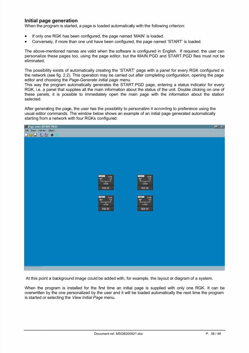
Initial page generationWhen the program is started, a page is loaded automatically with the following criterion:
• If only one RGK has been configured, the page named ‘MAIN’ is loaded.
• Conversely, if more than one unit have been configured, the page named ‘START’ is loaded.
The above-mentioned names are valid when the software is configured in English. If required, the user canpersonalize these pages too, using the page editor, but the MAIN.PGD and START.PGD files must not be
eliminated.
The possibility exists of automatically creating the ‘START’ page with a panel for every RGK configured inthe network (see fig. 2.2). This operation may be carried out after completing configuration, opening the pageeditor and choosing the Page-Generate initial page menu.This way the program automatically generates the START.PGD page, entering a status indicator for everyRGK, i.e. a panel that supplies all the main information about the status of the unit. Double clicking on one of these panels, it is possible to immediately open the main page with the information about the stationselected.
After generating the page, the user has the possibility to personalize it according to preference using theusual editor commands. The window below shows an example of an initial page generated automaticallystarting from a network with four RGKs configured:
At this point a background image could be added with, for example, the layout or diagram of a system.
When the program is installed for the first time an initial page is supplied with only one RGK. It can beoverwritten by the one personalized by the user and it will be loaded automatically the next time the programis started or selecting the View Initial Page menu.

5/16/2018 MSGB200921 - slidepdf.com
http://slidepdf.com/reader/full/msgb200921 39/48
Document ref. MSGB200921.doc P. 39 / 48
APPENDIX A – Connection modes
Direct RS-232 connectionFor direct RS-232 connection use the Lovato cable code 51C2. The cable can be connected also with theRGK and PC already powered. If everything is correct, starting the program it will be possible to switchdirectly to the Online mode. Please be reminded that this connection mode, which, due to its immediacy, isthe one more frequently used, should be used during RGK installation, set-up or maintenance, but it is not
suitable for a permanent type of connection, because by nature the RS232 interface cannot reach longdistances and may be affected by interference in an industrial environment.
In the event of problems…If the connection does not work (attempting to switch Online the program beeps and switches automaticallyto the Offline mode) carefully check the following points:
• The number of the COM: port of the PC used must correspond with that programmed in theConfiguration-Options-General-Serial port menu.
• The PC serial port must not be already used by another application.
• The serial address set on the RGK (in the Communication port menu) must be 01.
• The speed of the PC serial port (selectable with the Configuration-Options-General menu, default 9600
baud) must correspond with the one set in the device (in the Communication port menu, default 9600baud)
• The cable must be intact and correctly connected (from the RGK end it must be connected to the 6-pinRJ connector on the back of the device).
• The RGK must be powered and working.

5/16/2018 MSGB200921 - slidepdf.com
http://slidepdf.com/reader/full/msgb200921 40/48
Document ref. MSGB200921.doc P. 40 / 48
PC-RGK connection via RS-485 (RGK without internal RS-485 interface)Connection via the RS-485 interface involves the use of an RS232/RS485 converter for every node, i.e. oneconverter for the PC plus one converter for each RGK to be connected (from a minimum of 1 up to amaximum of 99 RGKs). The connection from the PC to the converter is through the Lovato cable code 51C4,while the one between the RGK and the converter is with cable code 51C6. The RS-485 outputs of theconverters should then be connected in parallel on Bus 485, formed of a screened duplex cable.Refer to the manual supplied with the converters for further details.
In the event of problems… If the connection does not work (attempting to switch to Online the program beeps and switchesautomatically to Offline) carefully check the following points:
• The PC COM: port number must correspond with the one programmed in the Configuration-Options-General-Serial port menu.
• The PC serial port speed (selectable with the Configuration-Options-General menu, default 9600 baud)must correspond with the one set in the devices (in the Communication port menu, default 9600 baud)
• If more than one RGKs are connected, they must be programmed with different serial communicationaddresses (01, 02, 03 etc). To set the RGK serial communication address, program the correspondingparameter in the device Communication port menu.
• The connection bias of the converters to the RS-485 bus must be correct (all the terminals marked A onone lead and all those marked B on the other).
• The maximum distance between the two farthest devices on the RS-485 bus may not exceed 1000m.
• All the converters must be powered and correctly configured (see the instructions provided with thedevices). In particular, the converter at the PC end must be programmed in the automatic switchingmode (date).
• If a converter supplied by Lovato is used, when there is communication on the RS-485 line, the yellowDATA led on the converter front panel flashes quickly.

5/16/2018 MSGB200921 - slidepdf.com
http://slidepdf.com/reader/full/msgb200921 41/48
Document ref. MSGB200921.doc P. 41 / 48
PC-RGK connection via RS-485 interface (RGK with internal interface)The connection of RGK units requires only one converter for the PC end. To connect the PC to the converter use a Lovato cable code 51C4. The connection between the RGK Units and the RS-485 bus is made directlywith duplex cable.
In the event of problems… If the connection does not work (attempting to switch to Online the program beeps and switchesautomatically to Offline) carefully check the following points:
• The COM: port number of the PC used must correspond with the one programmed in the Configuration-Options-General-Serial port menu.
• The PC serial port speed (selectable with the Configuration-Options-General menu, default 9600 baud)must correspond with the one set in the devices (in the Communication port menu, default 9600 baud)
• If more than one RGKs are connected, they must be programmed with different serial communicationaddresses (01, 02, 03 etc). To set the RGK serial communication address, program the correspondingparameter in the Communication port menu.
• For correct connection bias, terminals A11 of the RGK are to be connected to terminal A of theconverter, and terminals A12 with terminal B.
• The maximum distance between the two farthest devices on the RS-485 bus may not exceed 1000m.
• The converter at the PC end must be powered and correctly programmed in the automatic switchingmode (date).
• If a converter supplied by Lovato is used, when there is communication on the RS-485 line, the yellowDATA led on the converter front panel flashes quickly.

5/16/2018 MSGB200921 - slidepdf.com
http://slidepdf.com/reader/full/msgb200921 42/48
Document ref. MSGB200921.doc P. 42 / 48
Connection via standard modemTo make a remote connection via a switched telephone line the use of a pair of modems is necessary.Lovato guarantees correct operation of the connection using modems of the following type:
• 3-Com U.S. Robotics 56K model 5630
Though correct operation is possible also with modems of other types, in this manual all the configurationcommands (variables depending on the manufacturer) and the connection diagrams will refer to the above-mentioned modem model.
Though very simple in conception, connection via modem requires that the installer have a minimumof experience concerning the problems connected with serial communication, modem programming,types of telephone lines, etc. In an attempt to simplify the configuration procedure as far as possible,we have subdivided the operations to be carried out in the following steps:
1. Modem configuration at the RGK end From the RGK end the modem must be configured before it can be used. Configuration serves toimplement the following functions:
• Disable the echo
• Set a communication speed fixed at 9600 baud
• Permanently store the two previous settings as default at switch on
To make these configurations, the modem to be connected to the RGK will have to be momentarilyconnected to the PC with its standard cable. Then start the PM.EXE program (supplied together with thissoftware) and press the Program modem button. Wait for the confirmation message and then disconnectthe modem from the PC and connect it to the RGK. The PM.EXE program transmits the followingconfiguration string to the modem:
AT E0 &N6 &U6 &W0 <CR> (commands valid for modem model 5630)
If the user is familiar with terminal emulation programs (such as Windows Hyperterminal) thisprogramming can be done manually without the aid of the PM.EXE program. In this case, it will benecessary to set the serial interface at 9600 Baud, 8 bit, No parity, 1 stop bit and type in the above stringfrom the keyboard. On pressing return the modem will answer with OK confirming that programming has
taken place.
2. RGK configuration Also the RGK needs a configuration to be able to converse with the modem.
• Connect the PC to the RGK with the direct RS232 cable code 51C2.
• Check that the software revision in the RGK is 11 or higher
• Set the password
• From the Online mode, choose Modem parameters from the Parameters menu (see description onprevious pages).
• Activate the general modem enable (first option at top left).
• If you want the RGK to call the PC on its own initiative, activate the enable calls from RGK and Connect to PC boxes, specifying the PC modem telephone number and the conditions that will determine the call
(against alarm, periodical, etc.)• Transmit and store the settings with the Transmit button
3. System connection
• Connect the modem programmed at point 1 with the RGK using the cable code 51C5
• Connect the second modem to the PC with the standard cable provided with the modem. The PC-sidemodem does not require any particular programming (it must be left at factory defaults).
• Connect both modems to the respective telephone lines. For the first tests you are advised to use twointernal lines in the same office to keep the call under control.

5/16/2018 MSGB200921 - slidepdf.com
http://slidepdf.com/reader/full/msgb200921 43/48
Document ref. MSGB200921.doc P. 43 / 48
4. Configuration of the RGK.exe program
• Start the RGK.exe program from the PC with the modem already connected and powered.
• Choose the Configuration-Options menu
• Set the Connection via modem box from the General table.
• If the Modem phonebook table is empty, enter a record with the name of the installation and the phonenumber corresponding with the telephone line of the modem connected to the RGK.
• Click on OK to close and save the Options window.
5. Online Connection
• Choose Call with modem from the Communication menu
• From the pull-down box choose the name of the installation to be called. The corresponding telephonenumber (previously loaded in the Modem phonebook ) will be shown in the box below.
• Click on Dial
• At this point, the modem at the PC end calls the RGK modem. After a few rings the RGK modem and theprogram switch automatically to the online mode.
• To end the connection, choose Modem-Hang up from the Communication menu
In the event of problems…If during the attempted call the modem connected to the RGK does not ‘ring’, this means that the call fails to
reach its destination. In this case, carry out the following checks:• Try dialing the telephone number of the line to which the RGK is connected using a normal telephone.
The modem called should give off sounds that ought to be heard in the handset. If this does not happen,there are problems on the telephone line or on the switchboard.
• Check that PC modem is powered and connected with the cable to the correct serial port (the one set inCommunication-Serial port )
If the modem called rings repeatedly but the connection fails to be established (the window with the wording‘Connection OK' is not shown):
• Check the RGK programming (see previous point 2)
• Check the RGK-modem 51C5 cable
If the wording ‘Connection OK’ is shown on the PC but then the program switches to Offline:
• Try connecting directly from the PC to the RGK with cable 51C2 and carry out all the checks described inthe ‘Direct RS-232 connection’ chapter
• Check that the modem is programmed correctly as described in the previous point 1

5/16/2018 MSGB200921 - slidepdf.com
http://slidepdf.com/reader/full/msgb200921 44/48
Document ref. MSGB200921.doc P. 44 / 48
Connection via GSM modemTo make a remote connection through the GSM cellular network a GSM modem needs to be connected tothe RGK and a second, traditional or GSM modem has to be connected to the PC.Lovato guarantees correct operation of the connection using GSM modems of the following type:
• Funkanlagen Falcom A-2
This type of modem is highly versatile and allows access to functions that are not normally possible with atraditional modem (SMS, E-mail). However, though taking place at 9600 bps, transmission via ether needslonger signal transfer times, to the disadvantage of communication speed.
Though very simple in conception, connection via GSM modem requires that the installer have aminimum of experience concerning the problems connected with serial communication, modem programming, types of telephone lines, etc. In an attempt to simplify the configuration procedure asfar as possible, we have subdivided the operations to be carried out in the following steps:
1. Configuration of the GSM modem at the RGK end From the RGK end the modem must be configured before it can be used. Configuration serves toimplement the following functions:
• Disable the echo
• Set a fixed communication speed at 9600 baud• Disable the PIN request after switch on
• Set the SMS service provider number
• Set the SMS mode on ‘Text mode’
• Permanently store the two previous settings as default at switch on
To make these configurations the GSM modem to be connected to the RGK should be momentarilyconnected to the PC with its standard cable. Then start the PM.EXE program (supplied together with thissoftware) and press the GSM modem program button. Wait for the confirmation message and thendisconnect the GSM modem from the PC.
Important:
A SIM-CARD enabled for data transmission is needed to make the GSM modem work. A normal SIM-CARD for cell phone does not work if used with the GSM modem. Contact the SIM-CARDSupplier to have it enabled. If the SIM card has different phone numbers for voice and data, usethe phone number for data.
2. RGK configuration Also the RGK needs configuration to be able to converse with the modem.
• Connect the PC to the RGK with the direct cable RS232 (51C2).
• Check that the software revision in the RGK is 11 or over
• Set the password
• From the Online mode, choose Modem parameters from the Parameters menu (see description onprevious pages).
• Activate the general modem enable (first option at top left).
• Activate the GSM Modem option
• If you want the RGK to call the PC on its own initiative, activate the enable calls from RGK and Connect to PC boxes, specifying the PC modem telephone number in the phone number box and the conditionsthat will determine the call (against alarm and/or periodical)
• If you want the RGK to send an SMS message in the occurrence of the above-mentioned conditions,activate one or more Send SMS options and specify the number of the cell phone to which the SMS is tobe sent for each one of them.
• In the same way, if you want the RGK to send an electronic mail message, activate the Send E-mail option and specify the electronic mail address of the addressee in the special box.
• Transmit the settings with the Transmit button
3. System connection
• Connect the GSM modem programmed at point 1 with the RGK via cable code 51C7
• Connect the second modem to the PC using the standard cable provided with the modem
• Power the GSM modem and wait 30 seconds for initialisation

5/16/2018 MSGB200921 - slidepdf.com
http://slidepdf.com/reader/full/msgb200921 45/48
Document ref. MSGB200921.doc P. 45 / 48
4. Configuration of the RGK.exe program
• Start the RGK.exe program from the PC with the modem already connected and powered.
• Choose the Configuration-Options menu
• Set the Connection via modem box from the General table.
•
If the Modem phonebook table is empty, enter a record with the name of the installation and the phonenumber corresponding with the telephone line of the modem connected to the RGK.
• Click on OK to close and save the Options window
5. Online Connection
• Choose Call with modem from the Communication menu
• From the drop-down box choose the name of the installation to be called. The corresponding telephonenumber (previously loaded in the Modem phonebook ) will be shown in the box below.
• Click on Dial
• At this point, the modem at the PC end calls the RGK modem. After a few rings the RGK modem and theprogram switch automatically to the online mode.
•
To end the connection, choose Modem-hang up from the Communication menu
In the event of problems…If during the attempted call the GSM modem connected to the RGK does not ‘ring’, this means that the callfails to reach its destination. In this case, carry out the following checks:
• Check that the signal near the GSM modem is strong enough ( > 40%). To do this, use the PM.EXEprogram.
• Check that the PC modem is powered and connected with the cable to the correct serial port (the oneset in Configuration-Options-Serial port )
If the modem called rings repeatedly but the connection fails to be established (the window with the wording‘Connection OK' is not shown):
• Check the RGK programming (see previous point 2)
• Check the RGK-modem cable 51C7
• If you are using a phone line passing through a switchboard, try to use a direct line. Some switchboards‘alter’ the phone call and make it unrecognizable by the GSM modem.
If the PC shows the wording 'Connection OK' but then the program goes Offline:
• Check the quality of the GSM signal
• Try connecting directly from the PC to the RGK with cable 51C2 and carry out all the checks described inthe ‘Direct RS-232 connection’ chapter
• Check that the GSM modem is programmed correctly as described in the previous point 1

5/16/2018 MSGB200921 - slidepdf.com
http://slidepdf.com/reader/full/msgb200921 46/48
Document ref. MSGB200921.doc P. 46 / 48
Appendix B – Commands with SMS messagesIf a GSM modem is used it is possible to control the RGK from any cell phone sending SMS Messages. Fromthe cell phone, the user has to send an SMS with the required commands and forward it to the phonenumber of the GSM modem connected to the RGK. The command syntax is very simple as most of itreflects the wording on the front panel buttons: sending for example ‘MAN’ is the same as pressing the MANbutton on the front panel. This way, it will be possible to control any RGK from any place that can be reachedby the GSM signal.
To prevent unauthorized access, the commands are to be preceded by a password defined by the user during installation. If the SMS message is not preceded by the correct password, it will be ignored. If however the message comes from one of the cell phones defined as addressees of alarm messages (seemodem parameters window), the password will not be necessary.The following table lists the possible commands:
COMMAND FUNCTION
OFF Switches to OFF mode – Resets alarms
MAN Switches to MAN mode
AUT Switches to AUT mode
TEST Switches to TEST mode
START Simulates pressing the START button
STOP Simulates pressing the STOP button
MAINS Simulates pressing the MAINS button
GEN Simulates pressing the GEN button
PWD=<password> Enters the access password
TIMExx Waits xx seconds before continuing to perform the commands
The commands can be chained and spaced by a pause:
Example (assuming GENSET as access password)PWD=GENSET MAN TIME05 START Switch to manual, wait 5 sec and then attempt starting
Example:PWD=GENSET OFF Switch to OFF
To enable the execution of SMS commands it is necessary to enable the corresponding box in the ModemParameters window (see Modem Parameters chapter). In the same window the user has to specify thepassword intended to be used. As mentioned previously, if the cell phone used to send the commands is thesame one designated as addressee of the alarm messages, it will not be necessary to enter the password.In this case the telephone number (under Send SMS..) will have to be stored in international format, for example +393359609600.
Example:OFF TEST TIME90 OFF Reset alarms, switch to TEST, wait 90sec and return to OFF
After performing a sequence of commands the RGK will answer with a confirmation message that will be
sent to the cell phone that generated the message.The structure of the confirmation message is the following:
• RGK Identification
• Operating mode
• Mains voltages
• Generator voltages
• Generator frequency
• Battery voltage
• Engine hour meter
• Engine status (running or stopped)
• Mains contactor status (open or closed)
•
Generator contactor status (open or closed)• RGK general status (starting, stopping, alarm, etc)

5/16/2018 MSGB200921 - slidepdf.com
http://slidepdf.com/reader/full/msgb200921 47/48
Document ref. MSGB200921.doc P. 47 / 48
Example:PWD=GENSET MAN START Switch to MAN, attempt to start
RGK answers with:
Info AIRPORT GEN-SET STATION RGK identification Mode = MAN Operating mode Mains = 400V,399V,400V Mains voltageGen = 000V,000V,000V Generator voltage Freq = 00.0Hz Generator frequency Engine = Stop Engine status MC = On Mains contactor GC = Off Generator contactor Starting General status
If the password in the SMS message does not correspond with the one stored in the RGK, the commandswill not be performed and an invalid password answer will be sent.The SMS Commands function works with the same criterion and the same connection layout as the normalalarm signalling Autocall function. It is also possible to use the two functions at the same time. Refer to theModem parameters and Connection via GSM modem chapters for the details and how to solve problems.

5/16/2018 MSGB200921 - slidepdf.com
http://slidepdf.com/reader/full/msgb200921 48/48
Document ref. MSGB200921.doc P. 48 / 48
PENTIUM is a registered trademark of Intel CorporationWINDOWS is a registered trademark of Microsoft Corporation


