Embed Size (px)
DESCRIPTION
easycare
Citation preview
SERVICE MANUAL
CONTENTS1. TECHNICAL CHANGES ····································22. PART NAMES AND FUNCTIONS······················33. SPECIFICATION·················································44. OUTLINES AND DIMENSIONS ·························65. WIRING DIAGRAM ············································86. REFRIGERANT SYSTEM DIAGRAM················97. SERVICE FUNCTIONS ····································108. TROUBLESHOOTING······································119. DISASSEMBLY INSTRUCTIONS ····················25
10. PARTS LIST······················································3010-1. PARTS LIST·············································3010-2. RoHS PARTS LIST··································36
11. MICROPROCESSOR CONTROL·····················42
Wireless typeModels
MSZ-A09NAMSZ-A12NAMSZ-A15NAMSZ-A17NAMSZ-A24NAMSY-A15NAMSY-A17NAMSY-A24NA
No. OB450REVISED EDITION-A
SPLIT-TYPE, HEAT PUMP AIR CONDITIONERS
MSZ-A09NA MSY-A15NAMSZ-A12NA MSY-A17NAMSZ-A15NAMSZ-A17NA
INDOOR UNIT
Outdoor unit service manualMUZ-A·NA Series (OB451)MXZ-A·NA Series (OB444)
NOTE:This service manual describes technical data of the intdoor units.RoHS compliant products have <G> mark on the spec name plate.For servicing of RoHS compliant products, refer to the PARTS LIST (RoHS compliant).
Revision A:• PARTS LIST has been revised.
OB450-1.qxp 06.11.29 1:37 PM Page 1

2
1 TECHNICAL CHANGES
MSZ09UN ➔ MSZ-A09NAMSZ12UN ➔ MSZ-A12NAMSH15TN ➔ MSZ-A15NAMSH17TN ➔ MSZ-A17NAMSH24WN ➔ MSZ-A24NAMS15TN ➔ MSY-A15NAMS17TN ➔ MSY-A17NAMS24WN ➔ MSY-A24NA
1.Control method between indoor and outdoor has been changed.2.Indoor fan motor has been changed.3.Signal of remote controller has been changed. (It is not available for conventional models.)
Revision A:• PARTS LIST has been revised. (10-1.8, 10-2.8)
OB450-1.qxp 06.11.29 1:37 PM Page 2

3
PART NAMES AND FUNCTIONS2
MSZ-A09NA MSY-A15NAMSZ-A12NA MSY-A17NAMSZ-A15NAMSZ-A17NA
MSZ-A24NAMSY-A24NA
MSZ-A09NAMSZ-A12NAMSZ-A15NAMSZ-A17NAMSY-A15NAMSY-A17NA
Line flow fan
Air outlet
Vertical vane
Air inlet
Display section
Front panel
PanelHeat exchanger
Horizontal vane
Operation section
(When the front panel is opened)
Remote controller
Remote controlreceiving section
Catechin air filter
Air cleaning filter(Anti-Allergy Enzyme Filter, Blue bellows type)
Emergency operation switch
Emergency operation switch
Operation indicator lamp
Remote controlreceiving section
Operation Indicatorlamp
MSZ-A24NAMSY-A24NA
ACCESSORIES
1
2
3
4
5
6
7
8
Installation plate
Installation plate fixing screw 4 o 25 mm
Remote controller holder
Fixing screw for 3 o 3.5 o 1.6 mm (Black)
Battery (AAA) for remote controller
Wireless remote controller
Felt tape (Used for left or left-rear piping)
Conduit plate
1
7
1
2
2
1
1
–
1
8
1
2
2
1
1
1
MSZ-A24NAMSY-A24NA
MSZ-A09NA MSZ-A17NAMSZ-A12NA MSY-A15NAMSZ-A15NA MSY-A17NA
OB450-1.qxp 06.11.29 1:37 PM Page 3

4
3 SPECIFICATION
NOTE : Test conditions are based on ARI 210/240.❈ 1 : Rating conditions(cooling) — Indoor : 80˚FDB, 67˚FWB, Outdoor : 95˚FDB, (75˚FWB)
(heating) — Indoor : 70˚FDB, 60˚FWB, Outdoor : 47˚FDB, 43˚FWB ❈ 2 : (heating) — Indoor : 70˚FDB, 60˚FWB, Outdoor : 17˚FDB, 15˚FWB
Item Model MSZ-A12NAINDOOR UNIT MODEL External finishPower supplyMax. fuse size (time delay)/ Disconnect switchMin. circuit ampacityFan motor
Airflow Low—Med.—High
Moisture removalSound level Low-Med.-HighCond. drain connection O.D.
Dimensions
WeightREMOTE CONTROLLERControl voltage (by built-in transformer)
V, phase, Hz AA
F.L.ACFMCFMpt./h
dB(A)in.in.in.in.Ib.
MSZ-A12NA
1.00.76
353-240-159353(318)-240(215)-152(134)
3.222-34-42
23
MSZ-A09NA
1.00.76
307-222-159307(275)-229(205)-152(134)
2.322-33-38
23
White208/230, 1, 60
15
5/830-11/16
8-1/411-3/4
Wireless type12-24V DC
MSZ-A09NA
HEAT DryCOOL Dry (Wet)
WDH
Item Model MSZ-A17NA MSY-A17NAINDOOR UNIT MODEL External finishPower supplyMax. fuse size (time delay)/ Disconnect switchMin. circuit ampacityFan motor
Airflow Low—Med.—High
Moisture removalSound level Low-Med.-HighCond. drain connection O.D.
Dimensions
WeightREMOTE CONTROLLERControl voltage (by built-in transformer)
V, phase, Hz AA
F.L.ACFMCFMpt./h
dB(A)in.in.in.in.Ib.
1.00.76
381(342)-328(293)-268(240)5.1
23
1.00.76
381(342)-328(293)-268(240)4.7
23
381-314-254
34-40-45/34-38-44
—
34-40-45/ —
381-314-254
34-40-46/34-38-44
—
34-40-46/ —
White208/230, 1, 60
15
5/830-11/16
8-1/411-3/4
Wireless type12-24V DC
MSZ-A15NA MSY-A15NA
HEAT DryCOOL Dry (Wet)
WDH
HEAT DryCOOL Dry (Wet)
WDH
Item Model MSY-A24NAINDOOR UNIT MODEL External finishPower supplyMax. fuse size (time delay)/ Disconnect switchMin. circuit ampacityFan motor
Airflow Low—Med.—High
Moisture removalSound level Low-Med.-HighCond. drain connection O.D.
Dimensions
WeightREMOTE CONTROLLERControl voltage (by built-in transformer)
V, phase, Hz AA
F.L.ACFMCFMpt./h
dB(A)in.in.in.in.Ib.
MSY-A24NA
1.00.76—
568(508)-431(385)-296(265)7.3
34-40-49/ —
37
MSZ-A24NA
1.00.76
568-486-296568(508)-431(385)-296(265)
7.334-40-49/34-40-48
37
White208/230, 1, 60
15
5/843-5/1610-1/4
12-13/16
Wireless type12-24V DC
MSZ-A24NA
(Cooling/Heating)
(Cooling/Heating)
MSZ-A15NA MSY-A15NA MSZ-A17NA MSY-A17NA
-
-
-
OB450-1.qxp 06.11.29 1:37 PM Page 4

5
MSZ-A09NA
MSZ-A12NA
MSZ-A15NAMSZ-A15NAMSY-A15NAMSZ-A17NAMSZ-A17NAMSY-A17NAMSZ-A24NAMSZ-A24NAMSY-A24NA
Model Mode
HEAT
COOL
HEAT
COOL
HEAT
COOL
HEAT
COOL
HEAT
COOL
307307275353353318381381342381381342568568508
16.816.815.119.319.317.420.920.918.820.920.918.820.220.218.1
23.423.421.026.726.724.128.828.826.028.828.826.034.434.430.9
Air flow(CFM)
Air speed(ft./sec.)
Coveragerange (ft.)Function
DryDryWetDryDryWetDryDryWetDryDryWetDryDryWet
3-1. OPERATING RANGE(1) POWER SUPPLY
MSZ-A09NA MSY-A15NAMSZ-A12NA MSY-A17NAMSZ-A15NA MSY-A24NAMSZ-A17NAMSZ-A24NA
Rated voltage Guaranteed VoltageModel
Min. 198V Max. 253V208V 230V208/230V 1phase 60Hz
3-2. OUTLET AIR SPEED AND COVERAGE RANGE
(2) OPERATION
78% —
Function
Cooling
Heating
Standard temperature
Maximum temperature
Minimum temperature
Maximum humidity
Standard temperature
Maximum temperature
Minimum temperature
DB (˚F)
80
95
67
70
80
70
WB (˚F)
67
71
57
60
67
60
Indoor
DB (˚F)
95
115
14
47
75
14
WB (˚F)
—
—
—
43
65
13
Outdoor
Condition
Intake air temperature
● The air coverage range is the figure upto the position where the air speed is 1ft./sec., when air is blown out horizon-tally from the unit properly at the Highspeed position.The coverage range should be usedonly as a general guideline since itvaries according to the size of the roomand furniture arranged inside the room.
OB450-1.qxp 06.11.29 1:37 PM Page 5

6
4 OUTLINES AND DIMENSIONS
Unit : inch
11
-3/4
424-9/16
30-11/16
8-1/4 3/16
2-1/8
3/4
6-1
/4
2-5/16
Air in
Air out
Installation plate
Insulation [1-1/8
Drain hose [5/8(Connected part O.D)
Liquid line [1/4 19-11/16Gas line [3/8 16-15/16Insulation [1-3/8 O.D [3/4 I.D
{
6-1/8 6-1/8
7/8
1-3/413-3/16 12-5/81-
5/8
8-7/
16
10-1
/8
1-11
/16
8-7
/16
1/8
11
-5/1
6
2-3/42-3/16
2-3/16 2-3/168-7/8 8-7/8 9/1
61
0-3
/49
-3/1
6
Wall hole [2-9/16Indoor unit
Installation plate
7/16x13/16 Oblong hole7/16x1 Oblong hole
7/8
hole
MSZ-A09NA MSY-A15NAMSZ-A12NA MSY-A17NAMSZ-A15NAMSZ-A17NA
OB450-1.qxp 06.11.29 1:37 PM Page 6
7
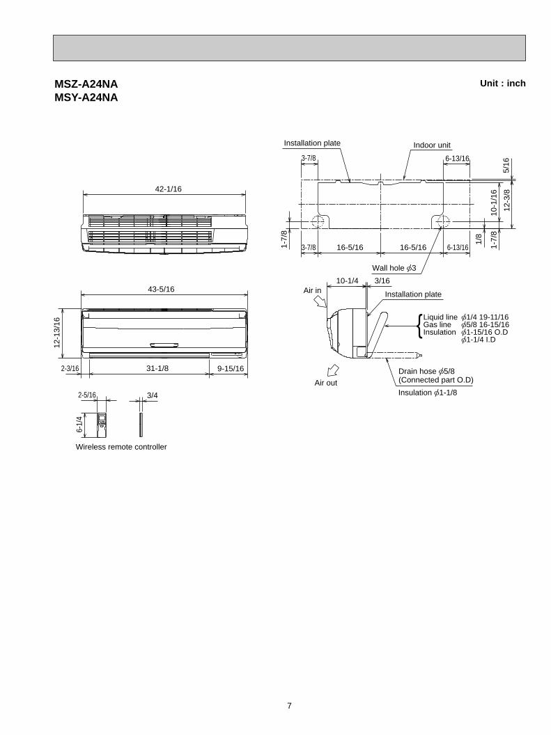
10-1/4
6-1/
4
3/42-5/16
1-7/
8
5/16
12-3
/8
10-1
/16
1-7/
8
1/8
3-7/8 6-13/16
3-7/8 6-13/1616-5/16 16-5/16
3/16
9-15/1631-1/82-3/16
42-1/16
43-5/16
12-1
3/16
Air out
Air in
Insulation [1-1/8
Drain hose [5/8(Connected part O.D)
Installation plate
Wall hole [3
Wireless remote controller
Installation plate Indoor unit
{Liquid line [1/4 19-11/16Gas line [5/8 16-15/16Insulation [1-15/16 O.D
[1-1/4 I.D
MSZ-A24NAMSY-A24NA
Unit : inch
OB450-1.qxp 06.11.29 1:37 PM Page 7
8
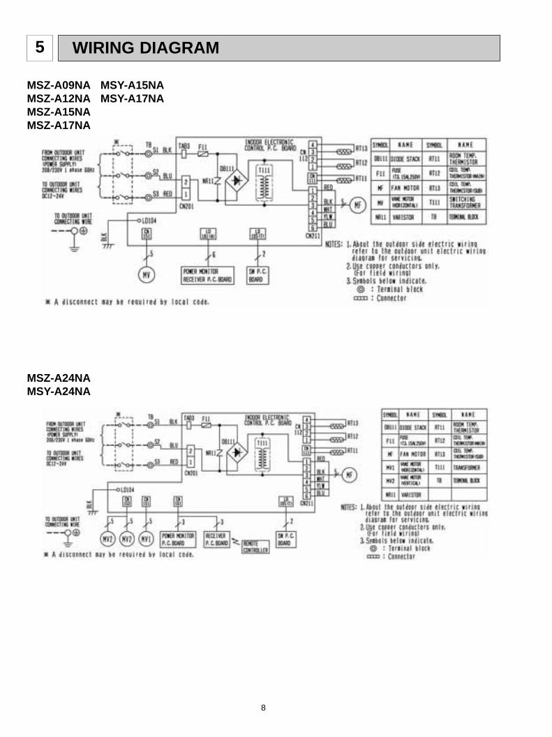
5 WIRING DIAGRAM
MSZ-A09NA MSY-A15NAMSZ-A12NA MSY-A17NAMSZ-A15NAMSZ-A17NA
MSZ-A24NAMSY-A24NA
OB450-1.qxp 06.11.29 1:37 PM Page 8

9
REFRIGERANT SYSTEM DIAGRAM6
MSZ-A09NAMSZ-A12NA
Indoorheatexchanger Flared connection
Room temperaturethermistorRT11
Indoor coil thermistorRT13(sub)
Flared connection
Refrigerant pipe [3/8(with heat insulator)
Refrigerant pipe [1/4(with heat insulator)
Indoor coil thermistorRT12(main)
Refrigerant flow in cooling
Refrigerant flow in heating
MSZ-A15NA MSY-A15NAMSZ-A17NA MSY-A17NA
Indoorheatexchanger
Room temperaturethermistorRT11
Refrigerant pipe [1/2(with heat insulator)
Flared connection
Flared connection
Indoor coilthermistorRT12(main)
Refrigerant pipe[1/4(with heat insulator)
Distributor
MSZ-A24NAMSY-A24NA
Indoorheatexchanger
Room temperaturethermistorRT11
Refrigerant pipe [5/8(with heat insulator)
Flared connection
Flared connection
Indoor coilthermistorRT12(main)
Refrigerant pipe [1/4(with heat insulator)
Distributor
Unit:inch
Indoor coilthermistorRT13(sub)
Indoor coilthermistorRT13(sub)
OB450-1.qxp 06.11.29 1:37 PM Page 9

10
7 SERVICE FUNCTIONS
7-2. P.C. BOARD MODIFICATION FOR INDIVIDUAL OPERATIONA maximum of 4 indoor units with wireless remote controllers can be used in a room.In this case, to operate each indoor unit individually by each remote controller, P.C. boards of remote controller must bemodified according to the number of the indoor unit.
7-1. TIMER SHORT MODEFor service, set time can be shortened by short circuit of JPG and JPS the indoor electronic control P.C. board.The time will be shortened as follows. (Refer to 8-7.)Set time : 1-minute ➔ 1-secondSet time : 3-minute ➔ 3-second (It takes 3 minutes for the compressor to start operation. However, the starting time is
shortened by short circuit of JPG and JPS.)
How to set the remote controller exclusively for particular indoor unitAfter you turn the breaker ON, the first remote controller that sends the signal to the indoor unit will be regarded as the remotecontroller for the indoor unit.The indoor unit will only accept the signal from the remote controller that has been assigned to the indoor unit once they areset.The setting will be cancelled if the breaker has turned off, or the power supply has shut down.Please conduct the above setting once again after the power has restored.
How to modify the remote controller P.C. boardRemove batteries before modification.The board has a print as shown below :
The P.C. board has the print “J1” and “J2”. Solder “J1” and “J2” according to the number of indoor unit as shown in Table 1.After modification, press the RESET button.
NOTE : For modification, take outthe batteries and press theOPERATE/STOP(ON/OFF)button twice or 3 times atfirst.After finish modification,put back the batteries thenpress the RESET button.J2J1
MSZ-A09NA MSZ-A12NA MSZ-A15NA MSZ-A17NA MSZ-A24NAMSY-A15NA MSY-A17NA MSY-A24NA
No. 1 unit
No. 2 unit
No. 3 unit
No. 4 unit
1 unit operation
No modification
–
–
–
2 units operation
Same as at left
Solder J1
–
–
3 units operation
Same as at left
Same as at left
Solder J2
–
4 units operation
Same as at left
Same as at left
Same as at left
Solder both J1 and J2
Table 1
OB450-1.qxp 06.11.29 1:37 PM Page 10

11
8-1. Cautions on troubleshooting1. Before troubleshooting, check the following:
1) Check the power supply voltage.2) Check the indoor/outdoor connecting wire for mis-wiring.
2. Take care of the following during servicing.1) Before servicing the air conditioner, be sure to turn off the unit first with the remote controller, and then after
confirming the horizontal vane is closed, turn off the breaker and / or disconnect the power plug.2) Be sure to turn OFF the power supply before removing the front panel, the cabinet, the top panel, and the
electronic control P.C. board.3) When removing the electronic control P.C. board, hold the edge of the board with care NOT to apply stress on the
components.4) When connecting or disconnecting the connectors, hold the housing of the connector. DO NOT pull the lead wires.
NOTE:• The operation settings are memorized when 10 seconds have passed after the indoor unit was operated with the
remote controller.• If main power is turned OFF or a power failure occurs while AUTO START/STOP timer is active, the timer setting is
cancelled.• If the unit has been off with the remote controller before power failure, the auto restart function does not work as the
power button of the remote controller is off.• To prevent breaker off due to the rush of starting current, systematize other home appliance not to turn on at the
same time.• When some air conditioners are connected to the same supply system, if they are operated before power failure,
the starting current of all the compressors may flow simultaneously at restart.Therefore, the special counter-measures are required to prevent the main voltage-drop or the rush of the startingcurrent by adding to the system that allows the units to start one by one.
JR07 CN15
1CN
211
CN11
2
BZ
7-3. AUTO RESTART FUNCTIONWhen the indoor unit is controlled with the remote controller, the operation mode, the set temperature, and the fan speedare memorized by the indoor electronic control P.C. board. The “AUTO RESTART FUNCTION” sets to work the momentpower has restored after power failure. Then, the unit will restart automatically. Operation1 If the main power has been cut, the operation settings remain.2 After the power is restored, the unit restarts automatically according to the memory.
(However, it takes at least 3 minutes for the compressor to start running.)How to release “AUTO RESTART FUNCTION”1Turn off the main power of the unit.2Solder the Jumper wire JR07 on the indoor electronic control P.C. board. (Refer to 8-7.)
JR07 CN15
1
CN152
CN10
1
CN21
1CN
112
BZ
MSZ-A24NAMSY-A24NA
MSZ-A09/12/15/17NAMSY-A15/17NA
Housing pointLead wiring
TROUBLESHOOTING8
MSZ-A09NA MSZ-A12NA MSZ-A15NA MSZ-A17NA MSZ-A24NAMSY-A15NA MSY-A17NA MSY-A24NA
OB450-1.qxp 06.11.29 1:37 PM Page 11

12
3. Troubleshooting procedure1) First, check if the OPERATION INDICATOR lamp on the indoor unit is flashing on and off to indicate an abnormality.
To make sure, check how many times the abnormality indication is flashing on and off before starting service work.2) Before servicing check that the connector and terminal are connected properly.3) If the electronic control P.C. board is supposed to be defective, check the copper foil pattern for disconnection and the
components for bursting and discoloration.4) When troubleshooting, refer to 8-2., 8-3. and 8-4.
4. How to replace batteriesWeak batteries may cause the remote controller malfunction.In this case, replace the batteries to operate the remote controller normally.
RESET button
Insert the negative pole of the batteries first. Check if the polarity of the batteries is correct.
NOTE : 1. If RESET button is not pressed, the remote controller may not operate correctly.2. This remote controller has a circuit to automatically reset the microcomputer when batteries are replaced.
This function is equipped to prevent the microcomputer from malfunctioning due to the voltage drop caused by the battery replacement.
2 Press RESET button with tip end of ball point penor the like, and then use the remote controller.
1 Remove the front lid and insert batteries.Then reattach the front lid.
INFORMATION FOR MULTI SYSTEM AIR CONDITIONER OUTDOOR UNIT : MXZ series
Multi system air conditioner can connect two or more indoor units with one outdoor unit. •Unit won’t operate in case the total capacity of indoor units exceeds the capacity of outdoor units. Do not connect indoor units beyond the outdoor unit capacity.Operation indicator lamp flashes as shown in the figure below.
•When you try to operate two or more indoor units with one outdoor unit simultaneously, one for the cooling andthe other for heating, the operation mode of the indoor unit that operates earlier is selected. The other indoor units cannot operate, indicating as shown in the figure below. In this case, please set all the indoor units tothe same operation mode.
•When indoor unit starts the operation while the defrosting of outdoor unit is being done, it takes a few minutes(max. 10 minutes) to blow out the warm air.
•In the heating operation, though indoor unit that does not operate may get warm or the sound of refrigerantflowing may be heard, they are not malfunction. The reason is that the refrigerant continuously flows into it.
OPERATION INDICATOR
Not lightedBlinking
Lighted
OB450-1.qxp 06.11.29 1:37 PM Page 12
13
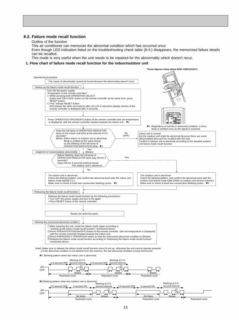
Outline of the functionThis air conditioner can memorize the abnormal condition which has occurred once.Even though LED indication listed on the troubleshooting check table (8-4.) disappears, the memorized failure details can be recalled.This mode is very useful when the unit needs to be repaired for the abnormality which doesn't recur.
8-2. Failure mode recall function
1. Flow chart of failure mode recall function for the indoor/outdoor unit
Operational procedure
Yes(Blinks)
No(OFF)
Yes
No
Releasing the failure mode recall function
Note1.Make sure to release the failure mode recall function once it's set up, otherwise the unit cannot operate properly. 2.If the abnormal condition is not deleted from the memory, the last abnormal condition is kept memorized.
W2. Blinking pattern when the indoor unit is abnormal:
W3.Blinking pattern when the outdoor unit is abnormal:
ONOFF
BeepsRepeated cycle Repeated cycle
ONOFF
No beep BeepsRepeated cycle
2.5-second OFFBlinking at 0.5-second interval
2.5-second OFF 3-second ONBlinking at 0.5-second interval
BeepsRepeated cycle
2.5-second OFFBlinking at 0.5-second interval
No beep BeepsRepeated cycle
2.5-second OFF 3-second ONBlinking at 0.5-second interval
Repeated cycle
Beeps
Does the left lamp of OPERATION INDICATORlamp on the indoor unit blink at the interval of 0.5seconds?Blinks: Either indoor or outdoor unit is abnormal. Beep is emitted at the same timing as the blinking of the left lamp of OPERATION INDICATOR lamp. W2
The cause of abnormality cannot be found because the abnormality doesn't recur.
Setting up the failure mode recall function
Before blinking, does the left lamp of OPERATION INDICATOR lamp stay ON for 3 seconds?Stays ON for 3 seconds (without beep): The outdoor unit is abnormal.
The indoor unit is abnormal.Check the blinking pattern, and confirm the abnormal point with the indoor unitfailure mode table(8-2.2.).Make sure to check at least two consecutive blinking cycles. W2
Turn ON the power supply.<Preparation of the remote controller>1 While pressing both OPERATION SELECT button and TOO COOL button on the remote controller at the same time, press RESET button.2 First, release RESET button. And release the other two buttons after all LCD in operation display section of the remote controller is displayed after 3 seconds.
Deleting the memorized abnormal condition
1After repairing the unit, recall the failure mode again according to "Setting up the failure mode recall function" mentioned above.2Press OPERATE/STOP(ON/OFF) button of the remote controller (the set temperature is displayed) with the remote controller headed towards the indoor unit.3Press EMERGENCY OPERATION switch so that the memorized abnormal condition is deleted.4Release the failure mode recall function according to "Releasing the failure mode recall function" mentioned above.
Repair the defective parts.
Release the failure mode recall function by the following procedures. • Turn OFF the power supply and turn it ON again.• Press RESET button of the remote controller.
Judgment of indoor/outdoor abnormality
Press OPERATE/STOP(ON/OFF) button of the remote controller (the set temperature is displayed) with the remote controller headed towards the indoor unit. W1
Indoor unit is normal.But the outdoor unit might be abnormal because there are some abnormalities that can't be recalled with this way.Confirm if outdoor unit is abnormal according to the detailed outdoor unit failure mode recall function.
The outdoor unit is abnormal.Check the blinking pattern, and confirm the abnormal point with theoutdoor unit failure mode table (Refer to outdoor unit service manual.)Make sure to check at least two consecutive blinking cycles. W3
W1. Regardless of normal or abnormal condition, a short beep is emitted once as the signal is received.
Those figures show about MSZ-A09/12/15/17.
OB450-1.qxp 06.11.29 1:37 PM Page 13

14
2. Indoor unit failure mode table
NOTE : Blinking patterns of this mode differ from the ones of Troubleshooting check table (8-4.).
12-time flash2.5-second OFF
Replace the indoor electronic controlP.C. board.Indoor control system
It cannot properly read data in thenonvolatile memory of the indoor electroniccontrol P.C. board.
11-time flash2.5-second OFF
Refer to 8-6.A "Check of indoor fanmotor".Indoor fan motor
The rotational frequency feedbacksignal is not emit during the 12 seconds theindoor fan operation.
2-time flash2.5-second OFF
Refer to the characteristics of the mainindoor coil thermistor, the sub indoor coilthermistor (8-7.).
Indoor coil thermistorThe indoor coil thermistor short or opencircuit is detected every 8 seconds during operation.
3-time flash2.5-second OFF
Refer to 8-6.D "How to check mis-wiringand serial signal error".
Serial signal The serial signal from outdoor unit is not received for a maximum of 6 minutes.
1-time flashevery 0.5-second
Refer to the characteristics of the roomtemperature thermistor (8-7.).
Room temperaturethermistor
The room temperature thermistor shortor open circuit is detected every 8seconds during operation.
Not lighted –Normal –
Left lamp of OPERATION INDICATOR lamp CorrespondenceAbnormal point
(Failure mode)Condition
OB450-1.qxp 06.11.29 1:37 PM Page 14

15
Start
Indoor unit operates.Outdoor unit doesn't operate.
Indoor unit doesn't receive the signal from remote controller.
OPERATION INDICATORlamp on the indoor unit is flashing on and off.
Outdoor unit operates onlyin Test Run operation. w
Outdoor unit doesn't operate even in Test Run operation. w
Indoor unit operates, when EMERGENCY OPERATION switch is pressed.
Indoor unit doesn't operate, when EMERGENCY OPERATION switch is pressed.
Check room temperature thermistor.Refer to 8-7. "Test point diagram and voltage".
Refer to"How to check inverter/compressor".
Refer to 8-6.B "Check of remote controller and receiver P.C. board".
1. Check indoor / outdoor connecting wire. (Check if the power is supplied to the indoor unit.)2. Refer to 8-6.C "Check of indoor electronic control P.C. board and indoor fan motor".
Unit doesn't operate normaloperation in COOL or HEAT mode.
Refer to "Check of R.V. coil".
Left lamp Flash on and offat 0.5-secondintervalsCause: Indoor/Outdoor unit• Mis-wiring or trouble of serial signal
Left lamp2-time flash Cause:Indoor unit• Trouble of room temp- erature/ indoor coil thermistor
Left lamp3-time flash Cause:Indoor unit• Trouble of indoor fan motor
Left lamp5-time flash Cause: Outdoor unit• Outdoor power system abnormality
Left lamp6-time flash Cause: Outdoor unit• Trouble of thermistor in outdoor unit
Left lamp7-time flash Cause: Outdoor unit• Trouble of outdoor control system
Refer to 8-6.D "How to check ofmis-wiringand serialsignal error".
Check room temperature thermistor and indoor coil thermis-tor.Refer to 8-7."Test point diagram and voltage".
Refer to 8-6.A "Check of indoor fan motor".
Refer to "How to checkinverter/ compressor".
Refer to "Check of outdoor thermistors".
Replace the inverter P.C. board or the outdoor electronic control P.C. board.
Left lamp14-time flash Cause: Outdoor unit• Other abnormality
Check "Flow chart of the detailed outdoor unit failure mode recall function."
Left lamp 4-time flash Cause:Indoor unit• Trouble of indoor unit control system
Replace the indoor electronic control P.C. board.
Refer to outdoor unit service manual.
Indoor unit operates.Outdoor unit doesn'toperate normally.
If blinking of OPERATION INDICATOR lamp cannot bechecked, it can be checked with failure mode recall function.
w"Test Run operation" means the operation within 30 minutes afterEMERGENCY OPERATION switch is pressed.
8-3. Instruction of troubleshooting
OB450-1.qxp 06.11.29 1:37 PM Page 15
16
No.
1
3
6
7
SymptomOperation indicator lamp Condition Correspondence
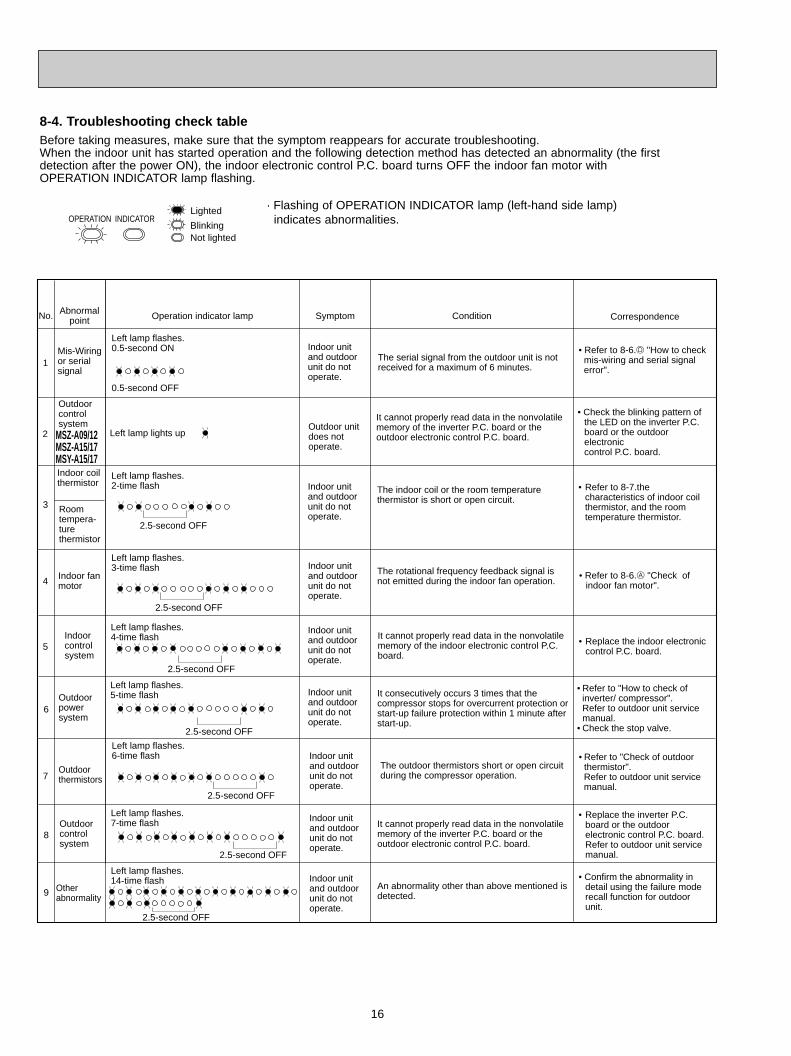
Left lamp flashes.0.5-second ON
0.5-second OFF
Mis-Wiringor serial signal
Outdoor power system
Outdoor thermistors
Outdoor control system
Indoor coil thermistor
The serial signal from the outdoor unit is not received for a maximum of 6 minutes.
It consecutively occurs 3 times that the compressor stops for overcurrent protection or start-up failure protection within 1 minute after start-up.
The outdoor thermistors short or open circuit during the compressor operation.
It cannot properly read data in the nonvolatile memory of the inverter P.C. board or the outdoor electronic control P.C. board.
• Refer to "Check of outdoor thermistor".
Refer to outdoor unit service manual.
• Refer to "How to check of inverter/ compressor".
Refer to outdoor unit servicemanual.
• Check the stop valve.
• Replace the inverter P.C.board or the outdoorelectronic control P.C. board.Refer to outdoor unit servicemanual.
• Refer to 8-6.D "How to check mis-wiring and serial signal
error".
4 Indoor fan motor
8
Abnormal point
Room tempera-ture thermistor
Left lamp flashes.2-time flash
2.5-second OFF
The indoor coil or the room temperature thermistor is short or open circuit.
• Refer to 8-7.thecharacteristics of indoor coilthermistor, and the roomtemperature thermistor.
Left lamp flashes.3-time flash
2.5-second OFF
The rotational frequency feedback signal is not emitted during the indoor fan operation.
• Refer to 8-6.A "Check of indoor fan motor".
Indoor unit and outdoor unit do not operate.
Indoor unit and outdoor unit do not operate.
Left lamp flashes.5-time flash
2.5-second OFF
Left lamp flashes.6-time flash
2.5-second OFF
Indoor unit and outdoor unit do not operate.
Indoor unit and outdoor unit do not operate.
Indoor unit and outdoor unit do not operate.
Other abnormality
An abnormality other than above mentioned is detected.
• Confirm the abnormality indetail using the failure moderecall function for outdoorunit.
Indoor unit and outdoor unit do not operate.
Indoor unit and outdoor unit do not operate.
9
5
Left lamp flashes.4-time flash
2.5-second OFF
Indoor control system
It cannot properly read data in the nonvolatile memory of the indoor electronic control P.C. board.
Indoor unit and outdoor unit do not operate.
• Replace the indoor electroniccontrol P.C. board.
Outdoor control system
It cannot properly read data in the nonvolatile memory of the inverter P.C. board or the outdoor electronic control P.C. board.
• Check the blinking pattern of the LED on the inverter P.C.board or the outdoor electronic control P.C. board.
2Outdoor unit does not operate.
Left lamp lights up MSZ-A09/12
MSZ-A15/17MSY-A15/17
Left lamp flashes.7-time flash
2.5-second OFF
Left lamp flashes.14-time flash
2.5-second OFF
8-4. Troubleshooting check table
Not lightedBlinking
OPERATION INDICATORLighted · Flashing of OPERATION INDICATOR lamp (left-hand side lamp)
indicates abnormalities.
Before taking measures, make sure that the symptom reappears for accurate troubleshooting.When the indoor unit has started operation and the following detection method has detected an abnormality (the first detection after the power ON), the indoor electronic control P.C. board turns OFF the indoor fan motor with OPERATION INDICATOR lamp flashing.
OB450-1.qxp 06.11.29 1:37 PM Page 16

17
OPERATION INDICATOR
Not lightedBlinking
Lighted
No. SymptomOperation indicator lamp Condition CorrespondenceAbnormal
point
1
MXZ typeOperation mode setting
Outdoor unit operates but indoor unit does not operate.
The operation mode of the each indoor unit is differently set to COOL(includes DRY) and HEAT at the same time, the operation mode of the indoor unit that has operated at first has the priority.
• Unify the operation mode. Refer to outdoor unit service manual.
2.5-second OFF
Right lamp flash
· Flashing of OPERATION INDICATOR lamp (right-hand side lamp) indicates abnormality.
· OPERATION INDICATOR lamp (left-hand side lamp) is lighted.
8-5. Trouble criterion of main parts
Part name FigureCheck method and criterion
Indoor fan motor(MF)
Measure the resistance with a tester.
Refer to 8-7. "Test point diagram and voltage", "Indoor electronic control P.C. board", the chart of thermistor.
Room temperaturethermistor(RT11)
Indoor coil thermistor(RT12(MAIN), RT13(SUB))
Horizontal vane motor(MV)MSZ-A09/12/15/17NAMSY-A15/17NA
NormalBRN-other one
Measure the resistance between the terminals with a tester.(Part temperature 50°F ~ 86°F)
235 " ~ 255 "Color of the lead wire
Check 8-6. A.
Horizontal vane motor(MV1)Vertical vanemotor(MV2)MSZ-A24NAMSY-A24NA
NormalBRN-other one
Measure the resistance between the terminals with a tester.(Part temperature 50°F ~ 86°F)
282 " ~ 306 "Color of the lead wire
RED
YLWBRN
ORN GRN
ROTOR
RED
YLWBRN
ORN GRN
ROTOR
MSZ-A09NA MSZ-A12NA MSZ-A15NAMSZ-A17NA MSZ-A24NAMSY-A15NA MSY-A17NA MSY-A24NA
OB450-1.qxp 06.11.29 1:37 PM Page 17

18
Check of indoor fan motorA
When OPERATION INDICATOR lamp flashes 3-time.Indoor fan does not operate.
w If more than 12 seconds or more passes after EMERGENCY OPERATION switch is pressed, the voltage mentioned above 2 goes 0V DC although the indoor electric control P.C. board is normal.
Indoor electroniccontrol P.C. board
Pay careful attention to the high voltage onthe fan motor connector CN211.
Yes
No
No
No(Changed)
Yes(Unchanged)
Is there any foreign matter thatinterferes the rotation of theline flow fan?
Turn OFF the power supply.
Remove the foreign matter andadjust the line flow fan.
Turn ON the power supply, wait 5 seconds or more, and then pressEMERGENCY OPERATION switch.Measure the supply voltage as follows within 12 secondsafter EMERGENCY OPERATION switch is pressed.If more than 12 seconds passes by, turn OFF the power supply andturn ON it again, then measure the voltage. w1.Measure the voltage between CN211 1(+) and 3(-).2.Measure the voltage between CN211 5(+) and 3(-).
Is there 294/325V DC betweenCN211 1 (+) and 3 (-), and does the voltage between CN211 5(+)and 3(-) rise to the range of 3 to 6VDC within 12 seconds after EMERGENCY OPERATION switch is pressed?
YesReplace the indoor fan motor.
CN211
Replace the indoor electronic control P.C. board.
The indoor fan motor error has occurred, and the indoor fan repeats "12-second ON and 30-second OFF" 3times, and then stops.
Measure the voltage between CN2116(+) and 3(-) while the fanmotor is rotating.
Is it unchanged holding0V DC or 15V DC?
Replace the indoor fan motor.
Replace the indoor electronic control P.C. board.
The indoor fan motor error has occurred, and the indoor fan doesn't operate.
8-6. Troubleshooting flow
OB450-1.qxp 06.11.29 1:37 PM Page 18

19
Check of remote controller and receiver P.C. board B
Indoor unit operates by pressing EMERGENCY OPERATION switch, but does not operate with the remote controller.
wCheck if the remote controller is exclusive for this air conditioner.
Yes
Replace the batteries. (Refer to 8-1.4.)
Turn ON a radio to AM and press switchON the remote controller.
Is noise heard from radio?
Are there any fluorescent lights ofinverter or rapid-start type withinthe range of 3.28ft.?
Replace the remote controller.
● Reinstall the unit away from lights.● Attach a filter on receiving part.
Switch ON the remote controller.
Is LCD display on the the remotecontroller visible?
Remove the batteries, then set them backand press RESET button. (Refer to 8-1.4.)Check if the unit operates with the remotecontroller.
Yes
Does the unit operate with theremote controller?
Yes
OK
No
(not clear)
Yes
No
No
Replace the receiver P.C. board.
Measure the voltage between receiver P.C. board connector CN301 No.2(+) and No.3(-) when the remote controller button is pressed.
Is the voltage approx. 4V DC?Replace the indoor electronic control P.C.board.
No (5V or 0V DC)
Yes
MSZ-A09/12/15/17NAMSY-A15/17NA
MSZ-A24NAMSY-A24NA
No
OB450-1.qxp 06.11.29 1:37 PM Page 19
20
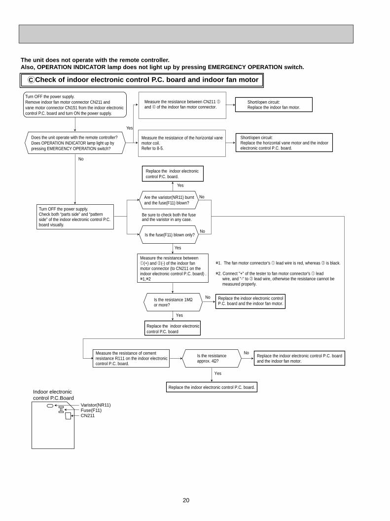
The unit does not operate with the remote controller.Also, OPERATION INDICATOR lamp does not light up by pressing EMERGENCY OPERATION switch.
Check of indoor electronic control P.C. board and indoor fan motorC
Yes
No
w1. The fan motor connector's 1 lead wire is red, whereas 3 is black.
w2. Connect "+" of the tester to fan motor connector's 1 lead wire, and "-" to 3 lead wire, otherwise the resistance cannot be measured properly.
Yes
No
Does the unit operate with the remote controller?Does OPERATION INDICATOR lamp light up by pressing EMERGENCY OPERATION switch?
Turn OFF the power supply.Remove indoor fan motor connector CN211 and vane motor connector CN151 from the indoor electronic control P.C. board and turn ON the power supply.
Measure the resistance of the horizontal vanemotor coil.Refer to 8-5.
Measure the resistance between CN211 3and 4 of the indoor fan motor connector.
Short/open circuit:Replace the indoor fan motor.
Short/open circuit:Replace the horizontal vane motor and the indoorelectronic control P.C. board.
Turn OFF the power supply.Check both “parts side” and “pattern side” of the indoor electronic control P.C. board visually.
Replace the indoor electronic control P.C. board.
Are the varistor(NR11) burntand the fuse(F11) blown?
Be sure to check both the fuse and the varistor in any case.
No
Yes
No
Is the fuse(F11) blown only?
Yes
No
Is the resistance 1M"or more?
Measure the resistance between1(+) and 3(-) of the indoor fanmotor connector (to CN211 on theindoor electronic control P.C. board) .w1,w2
Replace the indoor electronic control P.C. board
Replace the indoor electronic controlP.C. board and the indoor fan motor.
Is the resistanceapprox. 4"?
Measure the resistance of cement resistance R111 on the indoor electroniccontrol P.C. board.
Replace the indoor electronic control P.C. board.
Replace the indoor electronic control P.C. boardand the indoor fan motor.
Yes
CN211Fuse(F11)Varistor(NR11)
Indoor electroniccontrol P.C.Board
OB450-1.qxp 06.11.29 1:37 PM Page 20

21
How to check mis-wiring and serial signal errorD
Is there rated voltage AC in the power supply?
Is there any mis-wiring, poor contact, or wire disconnection of the indoor/outdoor connecting wire?
W1. Mis-wiring may damage indoor electronic control P.C. board during the operation. Be sure to confirm the wiring is correct before the operation starts.W3.Be sure to check this within 3 minutes after turning ON. After 3 minutes, LED blinks 6 times. Even when the inverter P.C.board or the outdoor electronic control P.C.board is normal, LED blinks 6 times after 3 minutes. (Except for outdoor unit of multi system type)
(Lighted or not lighted)
No
Yes
No
Yes
Yes
No
Yes
No
Yes
W2 Be careful to the residual voltage of smoothing capacitor.
Be sure to release the failure-moderecall function after checking.
No
No
Yes
No
Yes
Yes
Yes
No
Yes
Refer to outdoor unit service manual.
Turn OFF the power supply.
Turn ON the power supply.
Is there rated voltage betweenoutdoor terminal block S1 andS2?
Does the left lamp of OPERATION INDICATOR lamp light up? <Confirmation of the power to the indoor unit>
Press EMERGENCY OPERATION switch once.
Check the powersupply.
A
Turn OFF the power supply.Check once more if the indoor/outdoorconnecting wire is not mis-wiring.Short-circuit outdoor terminal block S2 andS3.W1
B
Turn ON the power supply.
Check the wiring.
Make them correct.
Turn OFF the power supply.Remove the short-circuit betweenoutdoor terminal block S2 and S3.Turn ON the power supply.Is there amplitude of 10 to 20V DCbetween outdoor terminal block S2and S3? <Confirmation of serialsignal>
Is there rated voltage between indoor terminal block S1 and S2?<Confirmation of power voltage>
Replace the indoor electronic control P.C. board.
Replace the inverter P.C. board or the outdoor electronic control P.C.board.W2
Is there any error of theindoor/outdoor connecting wire,such as the damage of the wire,intermediate connection, poorcontact to the terminal block?
Is there any error of theindoor/outdoor connecting wire,such as the damage of the wire,intermediate connection, poorcontact to the terminal block?
No
Replace theindoor/outdoorconnecting wire.
Replace theindoor/outdoorconnecting wire.
Is serial signalerror indicated 6 minutes later?
Yes
No
· Turn OFF inverter-controlled lighting equipment.
· Turn OFF the power supply and then turn ON again.
· Press EMERGENCY OPERATION switch.
B
· Reinstall either the unit or the light each other away.
· Attach a filter on remote control receiving section of the indoor unit.
A
Is serial signal error indicated 6 minutes later?
No
Does the LED on the inverter P.C. boardor the outdoor electronic control P.C.boardrepeat "3.6-second-OFF and 0.8-second-ONquick blinking"? W3
• When unit cannot operate neither by the remote controller nor by EMERGENCY OPERATION switch.Indoor unit does not operate.
• When OPERATION INDICATOR lamp flashes ON and OFF in every 0.5-second.Outdoor unit does not operate.
OB450-1.qxp 06.11.29 1:37 PM Page 21
22
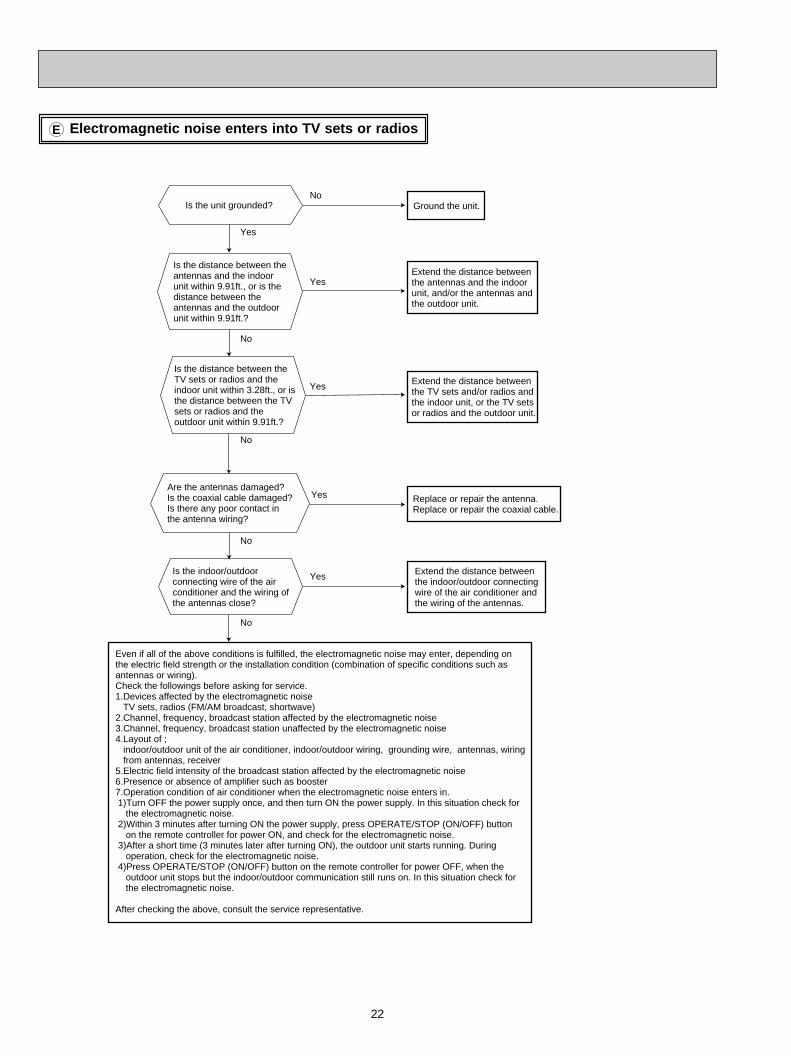
Electromagnetic noise enters into TV sets or radiosE
Replace or repair the antenna.Replace or repair the coaxial cable.
No
No
No
Yes
Yes
No
No
Yes
Yes
Yes
Is the distance between theantennas and the indoorunit within 9.91ft., or is thedistance between theantennas and the outdoorunit within 9.91ft.?
Is the distance between theTV sets or radios and theindoor unit within 3.28ft., or isthe distance between the TVsets or radios and theoutdoor unit within 9.91ft.?
Are the antennas damaged?Is the coaxial cable damaged?Is there any poor contact inthe antenna wiring?
Is the indoor/outdoorconnecting wire of the airconditioner and the wiring ofthe antennas close?
Even if all of the above conditions is fulfilled, the electromagnetic noise may enter, depending on the electric field strength or the installation condition (combination of specific conditions such as antennas or wiring).Check the followings before asking for service.1.Devices affected by the electromagnetic noise TV sets, radios (FM/AM broadcast, shortwave)2.Channel, frequency, broadcast station affected by the electromagnetic noise3.Channel, frequency, broadcast station unaffected by the electromagnetic noise4.Layout of ; indoor/outdoor unit of the air conditioner, indoor/outdoor wiring, grounding wire, antennas, wiring from antennas, receiver5.Electric field intensity of the broadcast station affected by the electromagnetic noise6.Presence or absence of amplifier such as booster7.Operation condition of air conditioner when the electromagnetic noise enters in. 1)Turn OFF the power supply once, and then turn ON the power supply. In this situation check for the electromagnetic noise. 2)Within 3 minutes after turning ON the power supply, press OPERATE/STOP (ON/OFF) button on the remote controller for power ON, and check for the electromagnetic noise. 3)After a short time (3 minutes later after turning ON), the outdoor unit starts running. During operation, check for the electromagnetic noise. 4)Press OPERATE/STOP (ON/OFF) button on the remote controller for power OFF, when the outdoor unit stops but the indoor/outdoor communication still runs on. In this situation check for the electromagnetic noise.
After checking the above, consult the service representative.
Is the unit grounded? Ground the unit.
Extend the distance betweenthe antennas and the indoorunit, and/or the antennas andthe outdoor unit.
Extend the distance betweenthe TV sets and/or radios andthe indoor unit, or the TV setsor radios and the outdoor unit.
Extend the distance betweenthe indoor/outdoor connectingwire of the air conditioner andthe wiring of the antennas.
OB450-1.qxp 06.11.29 1:37 PM Page 22
23
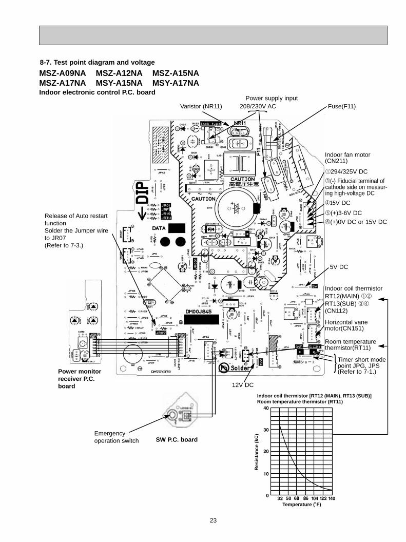
Indoor coil thermistor [RT12 (MAIN), RT13 (SUB)]Room temperature thermistor (RT11)
Temperature (˚F)
Res
ista
nce
(k"
)
MSZ-A09NA MSZ-A12NA MSZ-A15NAMSZ-A17NA MSY-A15NA MSY-A17NAIndoor electronic control P.C. board
Release of Auto restartfunctionSolder the Jumper wireto JR07(Refer to 7-3.)
208/230V AC Fuse(F11)
Indoor coil thermistorRT12(MAIN) 12
RT13(SUB) 34
(CN112)
Horizontal vane motor(CN151)
8-7. Test point diagram and voltage
SW P.C. board
Power monitorreceiver P.C.board 12V DC
5V DC
Power supply input
Indoor fan motor(CN211)
}Varistor (NR11)
Room temperaturethermistor(RT11)
} Timer short modepoint JPG, JPS(Refer to 7-1.)
5(+)3-6V DC
415V DC
3(-) Fiducial terminal ofcathode side on measur-ing high-voltage DC
1294/325V DC
6(+)0V DC or 15V DC
Emergency operation switch
OB450-1.qxp 06.11.29 1:37 PM Page 23

24
6(+)0V DC or 15V DC
Indoor coil thermistor [RT12 (MAIN), RT13 (SUB)]Room temperature thermistor (RT11)
Temperature (F˚)
Res
ista
nce
(k"
)
MSZ-A24NA MSY-24NAIndoor electronic control P.C. board
Release of Auto restartfunctionSolder the Jumper wireto JR07(Refer to 6-3.)
208/230V AC Fuse(F11)
Indoor coil thermistorRT12(MAIN)RT13(SUB)
Horizontal vane motor(CN151)
SW P.C. board
Receiver P.C. board
12V DC
5V DC
5(+)3-6V DC
415V DC
3(-) Fiducial terminal ofcathode side on measur-ing high-voltage DC
1294/325V DC
Power supply input
Indoor fan motor(CN211)
}Varistor (NR11)
Room temperaturethermistor(RT11)
} Timer shortmode point JPG, JPS(Refer to 7-1.)
Vertical vane motor (CN152)
DisplayP.C.board
OB450-1.qxp 06.11.29 1:37 PM Page 24
25
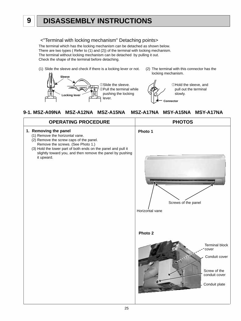
DISASSEMBLY INSTRUCTIONS9
(1) Slide the sleeve and check if there is a locking lever or not. (2) The terminal with this connector has the locking mechanism.
1Slide the sleeve.2Pull the terminal while pushing the locking lever.
1Hold the sleeve, and pull out the terminal slowly.
The terminal which has the locking mechanism can be detached as shown below.There are two types ( Refer to (1) and (2)) of the terminal with locking mechanism.The terminal without locking mechanism can be detached by pulling it out.Check the shape of the terminal before detaching.
<"Terminal with locking mechanism" Detaching points>
Connector
Sleeve
Locking lever
9-1. MSZ-A09NA MSZ-A12NA MSZ-A15NA MSZ-A17NA MSY-A15NA MSY-A17NA
OPERATING PROCEDURE PHOTOS
Photo 11. Removing the panel(1) Remove the horizontal vane. (2) Remove the screw caps of the panel.
Remove the screws. (See Photo 1.)(3) Hold the lower part of both ends on the panel and pull it
slightly toward you, and then remove the panel by pushing it upward.
Screws of the panel
Horizontal vane
Photo 2
Conduit cover
Screw of theconduit cover
Conduit plate
Terminal blockcover
OB450-1.qxp 06.11.29 1:37 PM Page 25

26
2. Removing the electronic control P.C. board, thepower monitor receiver P.C. board, SW P.C. boardand the terminal block(1) Remove the horizontal vane, the panel (Refer to 1.) and
the corner box. (2) Remove the screw of the conduit cover, and conduit cover.
(See Photo 2.)(3) Remove the indoor/outdoor connecting wire.
(4) Remove the switch holder from the electrical cover. (See Photo 3.)
(5) Remove the screw of the electrical cover, and then the electrical cover. (See Photo 3.)
(6) Remove the ground wire connected to the indoor electronic control P.C. board from the electrical box.
(See Photo 4.)(7) Unhook the power monitor receiver P.C. board holder from
the catch. (See Photo 3.)(8) Open the rear cover of the power monitor receiver P.C.
board holder and pull out the power monitor receiver P.C. board.
(9) Open the switch holder and pull out SW P.C. board.(10) Pull the electronic control P.C. board slightly toward you
from the electrical box, and disconnect TAB3 and all the connectors on the electronic control P.C. board. (LD101 and LD105 are direct-mounted to the electronic control P.C. board.)
(11) Pull out the electronic control P.C. board from the electrical box.
(12) Remove the ground wire connected to the heat exchangerfrom the electrical box. (See Photo 4.)
(13) Unhook the catches of the electrical box, and pull out the electrical box.
(14) Remove the screw of the terminal block cover, and thenremove the terminal block cover and the terminal block holder. (See Photo 5)
(15) Remove the terminal block by sliding it.
OPERATING PROCEDURE PHOTOS
Screw of the electrical cover.
Switch holder
Photo 3
3. Removing the electrical box(1) Remove the horizontal vane, the panel (Refer to 1.) and
the corner box. (2) Remove the screw of Conduit cover, and then the indoor/
outdoor connecting wire. (See Photo 2.)(3) Remove the switch holder and the electrical cover.
(See Photo 3.)(4) Remove the ground wire connected to the heat exchanger
from the electrical box. (See Photo 4.)(5) Disconnect the following connectors on the electronic
control P.C. board; the fan motor connector <CN211>, the indoor coil thermistor connector <CN112>, the vane motor connector <CN151>.
(6) Unhook the catches of the electrical box, and pull out the electrical box.
Photo 4
Indoor coil thermistorconnector (CN112)
Indoor fan motor connector (CN211)
Vane motor connector (CN151)
Ground wire
Photo 5
Screw
Power monitorreceiverP.C. board holder
OB450-1.qxp 06.11.29 1:38 PM Page 26
27
OPERATING PROCEDURE PHOTOS
Photo 7
Photo 9
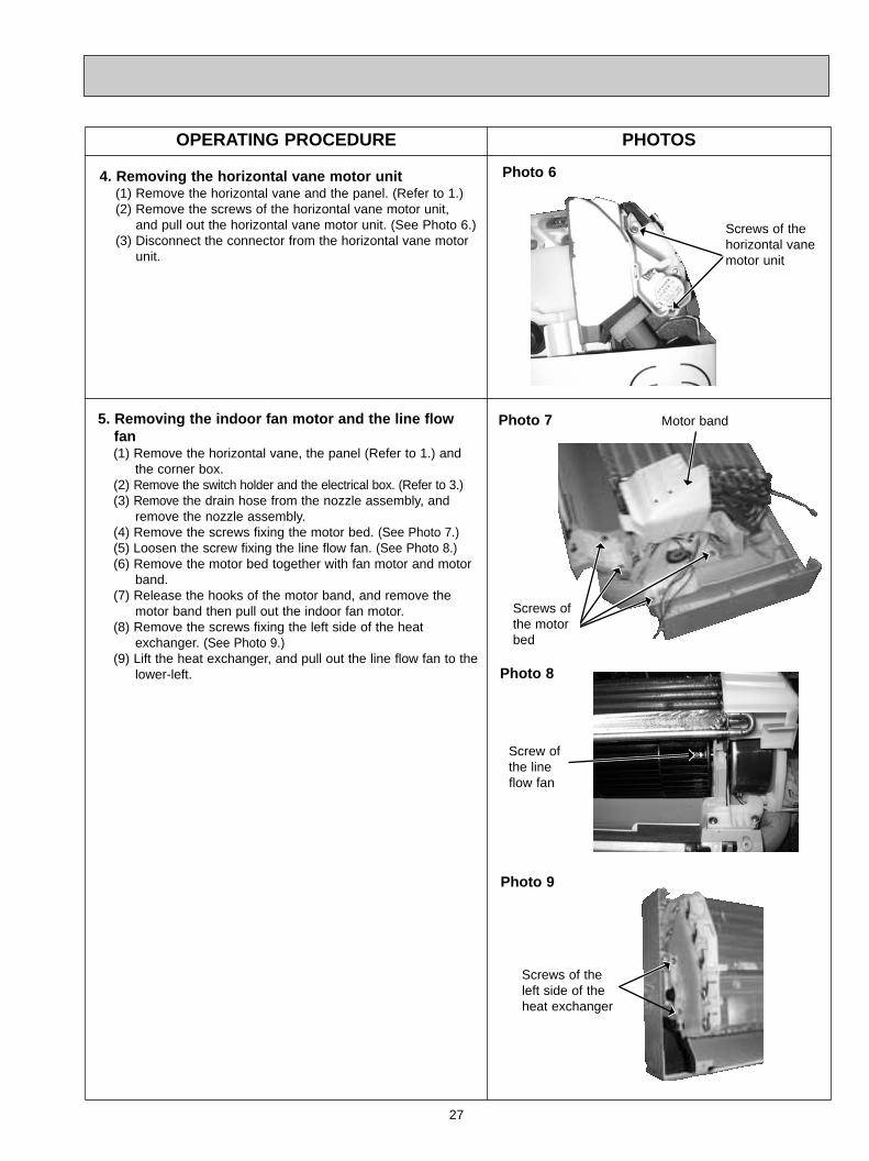
Screws of theleft side of theheat exchanger
4. Removing the horizontal vane motor unit(1) Remove the horizontal vane and the panel. (Refer to 1.)(2) Remove the screws of the horizontal vane motor unit,
and pull out the horizontal vane motor unit. (See Photo 6.)(3) Disconnect the connector from the horizontal vane motor
unit.
Photo 6
5. Removing the indoor fan motor and the line flowfan (1) Remove the horizontal vane, the panel (Refer to 1.) and
the corner box. (2) Remove the switch holder and the electrical box. (Refer to 3.)(3) Remove the drain hose from the nozzle assembly, and
remove the nozzle assembly.(4) Remove the screws fixing the motor bed. (See Photo 7.)(5) Loosen the screw fixing the line flow fan. (See Photo 8.)(6) Remove the motor bed together with fan motor and motor
band.(7) Release the hooks of the motor band, and remove the
motor band then pull out the indoor fan motor.(8) Remove the screws fixing the left side of the heat
exchanger. (See Photo 9.)(9) Lift the heat exchanger, and pull out the line flow fan to the
lower-left. Photo 8
Screw of the lineflow fan
Screws of the horizontal vane motor unit
Screws of the motorbed
Motor band
OB450-1.qxp 06.11.29 1:38 PM Page 27

28
9-2.MSZ-A24NA MSY-A24NA
OPERATING PROCEDURE PHOTOS
1. Removing the front panel(1) Remove the screw caps of the front panel.
Remove the screws.(2) Pull the panel down to your side slightly and unhook the
catches at the top.
Photo 1
Photo 2
Front panel
IndoorelectroniccontrolP.C. board
T.B. SW cover
Screws
R.Lholder
ReceiverP.C. board
2. Removing the electronic control P.C. board, the receiverP.C. board and the display P.C. board(1) Remove the front panel. (Refer to 1.)(2) Remove the corner box(3) Remove the screw of the electrical cover.
Remove the electrical cover and T.B. SW cover.(4) Remove the screw of the ground wire, which is solder-
mounted to the electronic control P.C. board. (5) Remove the R.L holder.(6) Remove the screw of the conduit cover. (7) Remove the conduit cover.(8) While pulling the electronic control P.C. board forward little
by little, disconnect all the connectors from the board.(9) Remove the electronic control P.C. board.(10) Open the R.L holder, remove the receiver P.C. board and
the display P.C. board.
Photo 33. Removing the electrical box(1) Remove the front panel. (Refer to 1.)(2) Remove the electrical cover. (Refer to 2.)(3) Disconnect the connector of the indoor coil thermistors.(4) Disconnect the indoor fan motor connector (CN211) and
the vane motor connector (CN151 and CN152) on theelectronic control P.C. board.
(5) Remove the screw of ground wire to the heat exchanger.(6) Remove the fan motor lead wire and indoor coil thermistor
from the electrical box.(7) Remove the lead wire of vane motor from the bottom of
electrical box.(8) Remove the screw fixing the electrical box and remove the
electrical box.
Screw of theelectrical box
Screw of theground wire
Corner box
Screw of T.B. SW cover
Screw of theelectrical cover
Conduit cover
Screw of the ground wire
Screw of conduit cover
OB450-1.qxp 06.11.29 1:38 PM Page 28

29
OPERATING PROCEDURE PHOTOS
Photo 4
Photo 6
Vane motors
4. Removing the vane motor(1) Remove the front panel. (Refer to 1.)(2) Remove the electrical cover. (Refer to 2.)(3) Remove the lead wire of vane motor.(Refer to 3.)(4) Remove the R.L. holder.(5) Pull out the drain hose from the nozzle assembly and
remove the nozzle assembly.(6) Remove the screws of the vane motor and disconnect the
connector.(7) Remove the vane motor.
Screws of the motor bed
5. Removing the line flow fan and the indoor fan motor(1) Remove the front panel. (Refer to 1.)(2) Remove the electrical box. (Refer to 3.)(3) Remove the drain hose from the nozzle assembly and
remove the nozzle assembly.(4) Remove the water cut.(5) Slide the hole cover and remove the hole cover.(6) Remove the hexagon socket set screw from the line flow
fan.(7) Remove the screws fixing the motor bed and remove the
fan motor. (Be careful not to drop the fan motor because itis heavy.)
(8) Remove the screws fixing the left side of the heat exchanger.
(9) Lift the left side of the heat exchanger.(10) Remove the line flow fan.
Screws fixingthe left sideof the heatexchanger
Screwsof thevanemotor
Screws of thevane motor
Vane motor
Photo 5
Photo 7
Photo 8
Holecover
Water cut
OB450-1.qxp 06.11.29 1:38 PM Page 29

30
10 PARTS LIST
10-1. PARTS LIST (non-RoHS compliant)MSZ-A09NA MSY-A15NAMSZ-A12NA MSY-A17NAMSZ-A15NAMSZ-A17NA1. INDOOR UNIT STRUCTURAL PARTS
No. Part No. Part name RemarksSymbol
in WiringDiagram
Q'ty/unit
12345678910
MSZ- MSY-
11
12
REMOTE CONTROLLERREMOTE CONTROLLERREMOTE CONTROLLER HOLDER
KM06AKM06C
BOXPANEL ASSEMBLY SCREW CAPFRONT PANEL CATECHIN AIR FILTER (LEFT)CATECHIN AIR FILTER (RIGHT)AIR CLEANING FILTERCORNER BOX (RIGHT)INSTALLATION PLATECONDUIT PLATE
Including No.3,42PCS/SET
MAC-415FT-E
E02 A32 234E02 A49 000E02 913 067E02 915 010E02 915 100E02 916 100
E02 A32 975E02 913 970E02 A49 978
11
11
E02 A54 426E02 A49 426E02 527 083
1121111111
1121111111
1121111111
1121111111
1121111111
1121111111
1
1
1
1
1
1
1
1
A09NA A12NA A15NA A17NA A15NA A17NA
1. INDOOR UNIT STRUCTURAL PARTS
2. ACCESSORY AND REMOTE CONTROLLER1
82
4
3
9
5 6
1211
2. ACCESSORY AND REMOTE CONTROLLER
7(See 10-5.)
10
OB450-1.qxp 06.11.29 1:38 PM Page 30
31
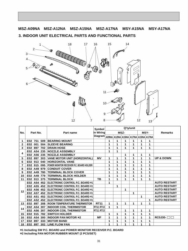
3. INDOOR UNIT ELECTRICAL PARTS AND FUNCTIONAL PARTS
MSZ-A09NA MSZ-A12NA MSZ-A15NA MSZ-A17NA MSY-A15NA MSY-A17NA
5
3
8
1
7
6
10
11
13
18
9
12
16 141517
BEARING MOUNTSLEEVE BEARINGDRAIN HOSENOZZLE ASSEMBLYNOZZLE ASSEMBLYVANE MOTOR UNIT (HORIZONTAL)HORIZONTAL VANEPOWER MONITOR RECEIVER P.C. BOARD HOLDERCONDUIT COVERTERMINAL BLOCK COVERTERMINAL BLOCK HOLDERTERMINAL BLOCKELECTRONIC CONTROL P.C. BOARD W1ELECTRONIC CONTROL P.C. BOARD W1ELECTRONIC CONTROL P.C. BOARD W1ELECTRONIC CONTROL P.C. BOARD W1ELECTRONIC CONTROL P.C. BOARD W1ELECTRONIC CONTROL P.C. BOARD W1ROOM TEMPERATURE THERMISTORINDOOR COIL THERMISTORINDOOR COIL THERMISTORSWITCH HOLDERINDOOR FAN MOTOR W2MOTOR BANDLINE FLOW FAN
UP & DOWN
AUTO RESTARTAUTO RESTARTAUTO RESTARTAUTO RESTARTAUTO RESTARTAUTO RESTART
RC0J30-
MV
TB
RT11RT12, RT13RT12, RT13
MF
No. Part No. Part name RemarksSymbol
in WiringDiagram
Q'ty/unit
123
4
567891011
12
13
14
15161718
E02 751 509E02 001 504 E02 897 702E02 A54 235E02 A56 235E02 897 303E02 913 040E02 915 095E02 A49 979E02 A49 780E02 A49 779E02 913 375E02 A54 452E02 A55 452E02 A56 452E02 A57 452E02 A51 452E02 A52 452E02 897 308E02 A54 307E02 A56 307E02 915 782E02 A54 300E02 897 333E02 897 302
111
11111111
1
1
11111
111
11111111
11
11111
W1 Including SW P.C. BOARD and POWER MONITOR RECEIVER P.C. BOARDW2 Including FAN MOTOR RUBBER MOUNT (2 PCS/SET)
MSZ- MSY-
A09NA A12NA A15NA A17NA A15NA A17NA1111
11111111
11
1111
1111
1111111
1
11
1111
111
11111111
1
1
11111
111
11111111
1
1
11111
4
2
12
OB450-2.qxp 06.11.29 1:40 PM Page 31

32
1
2
3
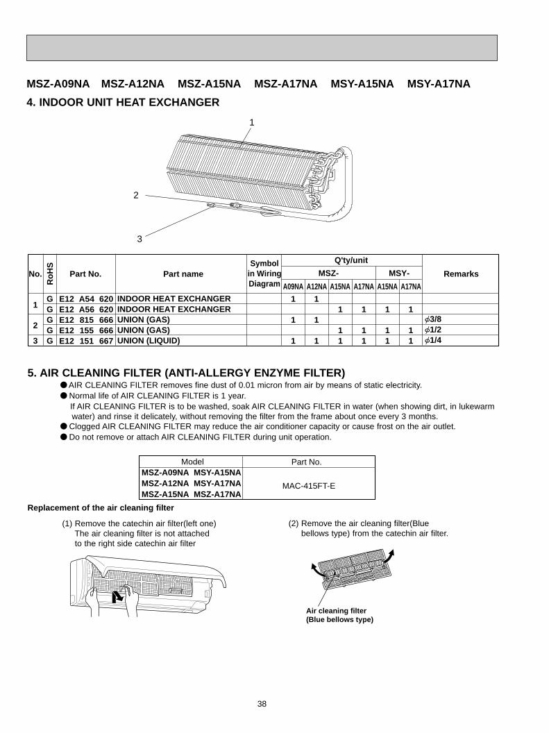
INDOOR HEAT EXCHANGERINDOOR HEAT EXCHANGERUNION (GAS)UNION (GAS)UNION (LIQUID)
{3/8{1/2{1/4
E02 A54 620E02 A56 620E02 815 666E02 155 666E02 151 667
1
1
1
1
11
1
11
1
1
1
1
11
1
11
MSZ- MSY-
A09NA A12NA A15NA A17NA A15NA A17NA
Q'ty/unit
No. Part No. Part name RemarksSymbol
in WiringDiagram
1
4. INDOOR UNIT HEAT EXCHANGER
3
2
Model Part No.
MAC-415FT-E
MSZ-A09NAMSZ-A12NAMSZ-A15NA
MSY-A15NAMSY-A17NAMSZ-A17NA
Air cleaning filter(Blue bellows type)
(1) Remove the catechin air filter(left one)The air cleaning filter is not attachedto the right side catechin air filter
(2) Remove the air cleaning filter(Bluebellows type) from the catechin air filter.
Replacement of the air cleaning filter
5. AIR CLEANING FILTER (ANTI-ALLERGY ENZYME FILTER)● AIR CLEANING FILTER removes fine dust of 0.01 micron from air by means of static electricity.● Normal life of AIR CLEANING FILTER is 1 year.
If AIR CLEANING FILTER is to be washed, soak AIR CLEANING FILTER in water (when showing dirt, in lukewarm water) and rinse it delicately, without removing the filter from the frame about once every 3 months.
● Clogged AIR CLEANING FILTER may reduce the air conditioner capacity or cause frost on the air outlet.● Do not remove or attach AIR CLEANING FILTER during unit operation.
MSZ-A09NA MSZ-A12NA MSZ-A15NA MSZ-A17NA MSY-A15NA MSY-A17NA
OB450-2.qxp 06.11.29 1:40 PM Page 32
33
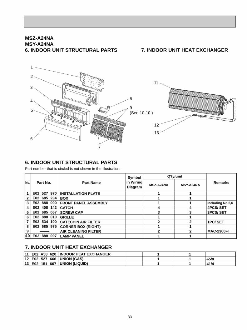
MSZ-A24NAMSY-A24NA6. INDOOR UNIT STRUCTURAL PARTS
MSZ-A24NA MSY-A24NA
E02 527 970E02 685 234E02 888 000E02 408 142E02 685 067E02 888 010E02 534 100E02 685 975-
E02 888 007
INSTALLATION PLATEBOX FRONT PANEL ASSEMBLYCATCHSCREW CAP GRILLECATECHIN AIR FILTERCORNER BOX (RIGHT) AIR CLEANING FILTERLAMP PANEL
Symbolin WiringDiagram
Q'ty/unit
Including No.5,64PCS/ SET3PCS/ SET
1PC/ SET
MAC-2300FT
RemarksPart No.No. Part Name
12345678910
1114312121
1114312121
7. INDOOR UNIT HEAT EXCHANGER
2
4
5
7
6
1
11
8
12
13
3
E02 A58 620E02 527 666E02 151 667
{5/8{1/4
111
111
INDOOR HEAT EXCHANGERUNION (GAS)UNION (LIQUID)
111213
7. INDOOR UNIT HEAT EXCHANGER
6. INDOOR UNIT STRUCTURAL PARTS
9(See 10-10.)
Part number that is circled is not shown in the illustration.
OB450-2.qxp 06.11.29 1:40 PM Page 33
34
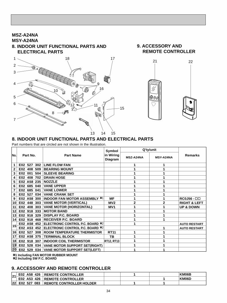
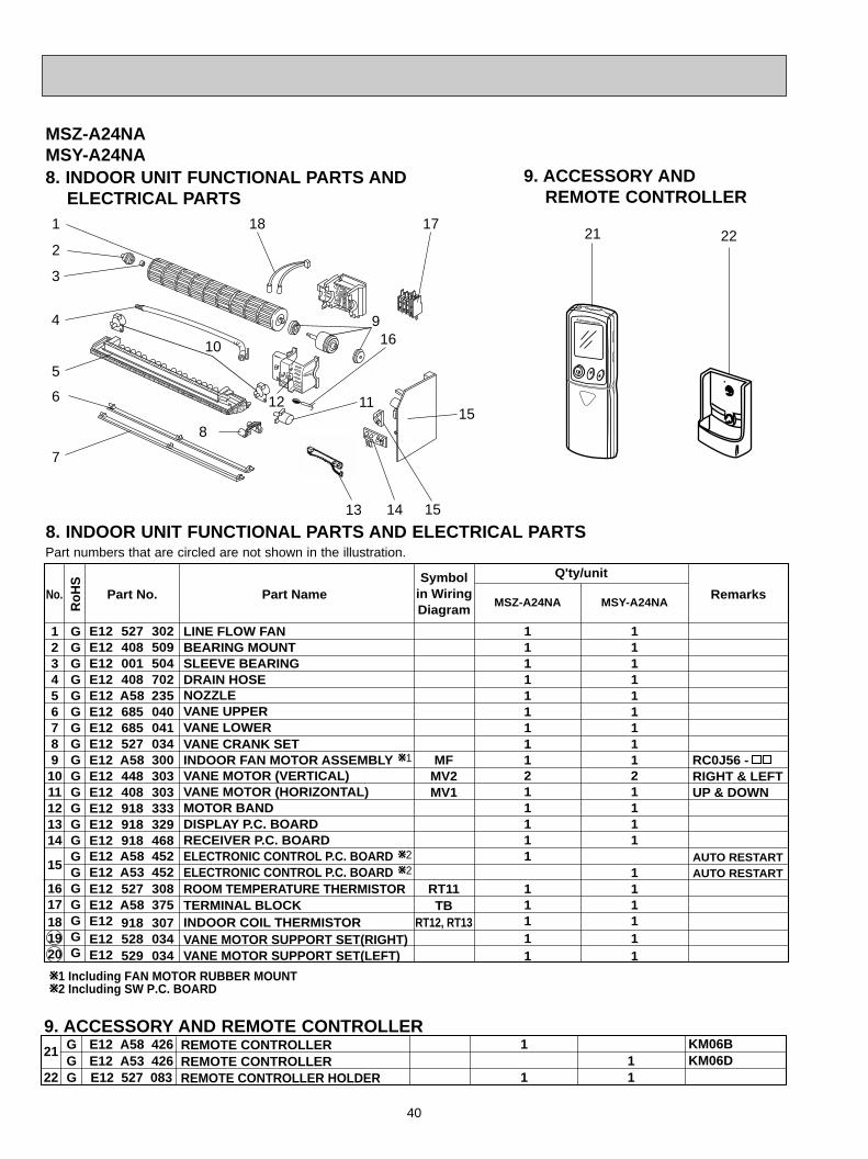
E02 527 302E02 408 509E02 001 504E02 408 702E02 A58 235E02 685 040E02 685 041E02 527 034E02 A58 300E02 448 303E02 408 303E02 918 333E02 918 329E02 918 468E02 A58 452E02 A53 452E02 527 308E02 A58 375E02 918 307E02 528 034E02 529 034
1234567891011121314
15
1617181920
LINE FLOW FANBEARING MOUNTSLEEVE BEARINGDRAIN HOSENOZZLE VANE UPPERVANE LOWER VANE CRANK SETINDOOR FAN MOTOR ASSEMBLYVANE MOTOR (VERTICAL)VANE MOTOR (HORIZONTAL)MOTOR BANDDISPLAY P.C. BOARDRECEIVER P.C. BOARDELECTRONIC CONTROL P.C. BOARDELECTRONIC CONTROL P.C. BOARDROOM TEMPERATURE THERMISTORTERMINAL BLOCKINDOOR COIL THERMISTORVANE MOTOR SUPPORT SET(RIGHT)VANE MOTOR SUPPORT SET(LEFT)
Symbolin WiringDiagram
Q'ty/unit
RIGHT & LEFTUP & DOWN
RemarksPart No.No. Part Name
MFMV2MV1
RT11TB
RT12, RT13
11111111121 1111
11111
11111111121 111
111111
RC0J56 -
AUTO RESTARTAUTO RESTART
MSZ-A24NA MSY-A24NA
W1
W2W2
W1 Including FAN MOTOR RUBBER MOUNTW2 Including SW P.C. BOARD
Part numbers that are circled are not shown in the illustration.
MSZ-A24NAMSY-A24NA
9. ACCESSORY AND REMOTE CONTROLLER
8. INDOOR UNIT FUNCTIONAL PARTS AND ELECTRICAL PARTS
21 22
8. INDOOR UNIT FUNCTIONAL PARTS AND ELECTRICAL PARTS
17
2
6
4
7
11
5
3
10
1
16
18
815
21
22
E02 A58 426E02 A53 426E02 527 083
REMOTE CONTROLLERREMOTE CONTROLLERREMOTE CONTROLLER HOLDER
1
111
KM06BKM06D
9. ACCESSORY AND REMOTE CONTROLLER
13 14
9
12
15
OB450-2.qxp 06.11.29 1:40 PM Page 34
35
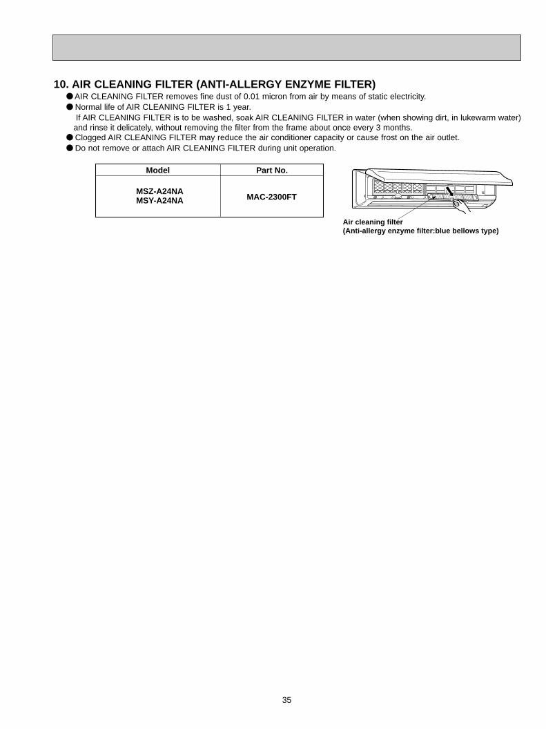
Model Part No.
MAC-2300FTMSZ-A24NAMSY-A24NA
Air cleaning filter (Anti-allergy enzyme filter:blue bellows type)
10. AIR CLEANING FILTER (ANTI-ALLERGY ENZYME FILTER)● AIR CLEANING FILTER removes fine dust of 0.01 micron from air by means of static electricity.● Normal life of AIR CLEANING FILTER is 1 year.
If AIR CLEANING FILTER is to be washed, soak AIR CLEANING FILTER in water (when showing dirt, in lukewarm water)and rinse it delicately, without removing the filter from the frame about once every 3 months.
● Clogged AIR CLEANING FILTER may reduce the air conditioner capacity or cause frost on the air outlet.● Do not remove or attach AIR CLEANING FILTER during unit operation.
OB450-2.qxp 06.11.29 1:40 PM Page 35
36
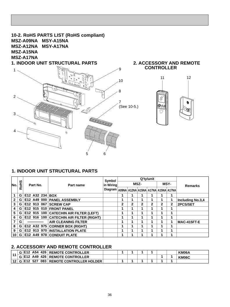
10-2. RoHS PARTS LIST (RoHS compliant)MSZ-A09NA MSY-A15NAMSZ-A12NA MSY-A17NAMSZ-A15NAMSZ-A17NA1. INDOOR UNIT STRUCTURAL PARTS
No.
Ro
HS
Part No. Part name RemarksSymbol
in WiringDiagram
Q'ty/unit
12345678910
GGGGGGGGGG
GGG
MSZ- MSY-
11
12
REMOTE CONTROLLERREMOTE CONTROLLERREMOTE CONTROLLER HOLDER
KM06AKM06C
BOXPANEL ASSEMBLY SCREW CAPFRONT PANEL CATECHIN AIR FILTER (LEFT)CATECHIN AIR FILTER (RIGHT)AIR CLEANING FILTERCORNER BOX (RIGHT)INSTALLATION PLATECONDUIT PLATE
Including No.3,42PCS/SET
MAC-415FT-E
E12 A32 234E12 A49 000E12 913 067E12 915 010E12 915 100E12 916 100
E12 A32 975E12 913 970E12 A49 978
11
11
E12 A54 426E12 A49 426E12 527 083
1121111111
1121111111
1121111111
1121111111
1121111111
1121111111
1
1
1
1
1
1
1
1
A09NA A12NA A15NA A17NA A15NA A17NA
1. INDOOR UNIT STRUCTURAL PARTS
2. ACCESSORY AND REMOTE CONTROLLER1
82
4
3
9
5 6
1211
2. ACCESSORY AND REMOTE CONTROLLER
7(See 10-5.)
10
OB450-2.qxp 06.11.29 1:40 PM Page 36
37
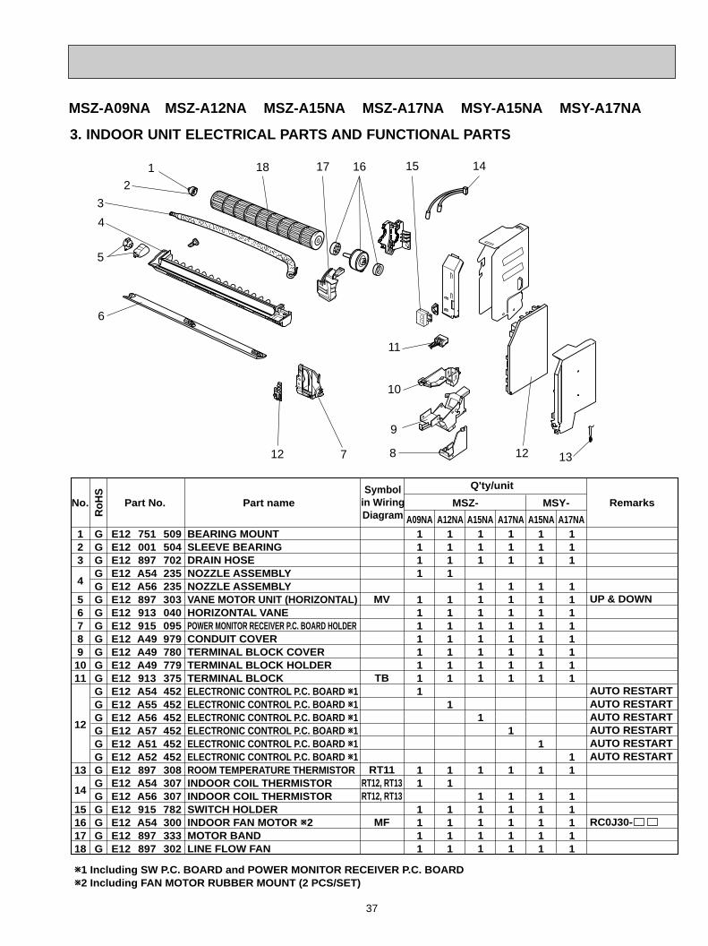
3. INDOOR UNIT ELECTRICAL PARTS AND FUNCTIONAL PARTS
MSZ-A09NA MSZ-A12NA MSZ-A15NA MSZ-A17NA MSY-A15NA MSY-A17NA
5
3
8
1
7
6
10
11
13
18
9
12
16 141517
BEARING MOUNTSLEEVE BEARINGDRAIN HOSENOZZLE ASSEMBLYNOZZLE ASSEMBLYVANE MOTOR UNIT (HORIZONTAL)HORIZONTAL VANEPOWER MONITOR RECEIVER P.C. BOARD HOLDERCONDUIT COVERTERMINAL BLOCK COVERTERMINAL BLOCK HOLDERTERMINAL BLOCKELECTRONIC CONTROL P.C. BOARD W1ELECTRONIC CONTROL P.C. BOARD W1ELECTRONIC CONTROL P.C. BOARD W1ELECTRONIC CONTROL P.C. BOARD W1ELECTRONIC CONTROL P.C. BOARD W1ELECTRONIC CONTROL P.C. BOARD W1ROOM TEMPERATURE THERMISTORINDOOR COIL THERMISTORINDOOR COIL THERMISTORSWITCH HOLDERINDOOR FAN MOTOR W2MOTOR BANDLINE FLOW FAN
UP & DOWN
AUTO RESTARTAUTO RESTARTAUTO RESTARTAUTO RESTARTAUTO RESTARTAUTO RESTART
RC0J30-
MV
TB
RT11RT12, RT13RT12, RT13
MF
No. Part No. Part name RemarksSymbol
in WiringDiagram
Q'ty/unit
123
4
567891011
12
13
14
15161718
RoH
S
GGGGGGGGGGGGGGGGGGGGGGGGG
E12 751 509E12 001 504 E12 897 702E12 A54 235E12 A56 235E12 897 303E12 913 040E12 915 095E12 A49 979E12 A49 780E12 A49 779E12 913 375E12 A54 452E12 A55 452E12 A56 452E12 A57 452E12 A51 452E12 A52 452E12 897 308E12 A54 307E12 A56 307E12 915 782E12 A54 300E12 897 333E12 897 302
111
11111111
1
1
11111
111
11111111
11
11111
W1 Including SW P.C. BOARD and POWER MONITOR RECEIVER P.C. BOARDW2 Including FAN MOTOR RUBBER MOUNT (2 PCS/SET)
MSZ- MSY-
A09NA A12NA A15NA A17NA A15NA A17NA1111
11111111
11
1111
1111
1111111
1
11
1111
111
11111111
1
1
11111
111
11111111
1
1
11111
4
2
12
OB450-2.qxp 06.11.29 1:40 PM Page 37
38
1
2
3
GGGGG
INDOOR HEAT EXCHANGERINDOOR HEAT EXCHANGERUNION (GAS)UNION (GAS)UNION (LIQUID)
{3/8{1/2{1/4
E12 A54 620E12 A56 620E12 815 666E12 155 666E12 151 667
1
1
1
1
11
1
11
1
1
1
1
11
1
11
MSZ- MSY-
A09NA A12NA A15NA A17NA A15NA A17NA
Q'ty/unit
No.
Ro
HS
Part No. Part name RemarksSymbol
in WiringDiagram
1
4. INDOOR UNIT HEAT EXCHANGER
3
2
Model Part No.
MAC-415FT-E
MSZ-A09NAMSZ-A12NAMSZ-A15NA
MSY-A15NAMSY-A17NAMSZ-A17NA
Air cleaning filter(Blue bellows type)
(1) Remove the catechin air filter(left one)The air cleaning filter is not attachedto the right side catechin air filter
(2) Remove the air cleaning filter(Bluebellows type) from the catechin air filter.
Replacement of the air cleaning filter
5. AIR CLEANING FILTER (ANTI-ALLERGY ENZYME FILTER)● AIR CLEANING FILTER removes fine dust of 0.01 micron from air by means of static electricity.● Normal life of AIR CLEANING FILTER is 1 year.
If AIR CLEANING FILTER is to be washed, soak AIR CLEANING FILTER in water (when showing dirt, in lukewarm water) and rinse it delicately, without removing the filter from the frame about once every 3 months.
● Clogged AIR CLEANING FILTER may reduce the air conditioner capacity or cause frost on the air outlet.● Do not remove or attach AIR CLEANING FILTER during unit operation.
MSZ-A09NA MSZ-A12NA MSZ-A15NA MSZ-A17NA MSY-A15NA MSY-A17NA
OB450-2.qxp 06.11.29 1:40 PM Page 38

39
MSZ-A24NAMSY-A24NA6. INDOOR UNIT STRUCTURAL PARTS
MSZ-A24NA MSY-A24NA
E12 527 970E12 685 234E12 888 000E12 408 142E12 685 067E12 888 010E12 534 100E12 685 975-
E12 888 007
INSTALLATION PLATEBOX FRONT PANEL ASSEMBLYCATCHSCREW CAP GRILLECATECHIN AIR FILTERCORNER BOX (RIGHT) AIR CLEANING FILTERLAMP PANEL
Symbolin WiringDiagram
Q'ty/unit
Including No.5,64PCS/ SET3PCS/ SET
1PC/ SET
MAC-2300FT
RemarksPart No.No. Part Name
12345678910
RoHS
GGGGGGGGGG
1114312121
1114312121
7. INDOOR UNIT HEAT EXCHANGER
2
4
5
7
6
1
11
8
12
13
3
E12 A58 620E12 527 666E12 151 667
{5/8{1/4
111
111
INDOOR HEAT EXCHANGERUNION (GAS)UNION (LIQUID)
111213
GGG
7. INDOOR UNIT HEAT EXCHANGER
6. INDOOR UNIT STRUCTURAL PARTS
9(See 10-10.)
Part number that is circled is not shown in the illustration.
OB450-2.qxp 06.11.29 1:40 PM Page 39
40
E12 527 302E12 408 509E12 001 504E12 408 702E12 A58 235E12 685 040E12 685 041E12 527 034E12 A58 300E12 448 303E12 408 303E12 918 333E12 918 329E12 918 468E12 A58 452E12 A53 452E12 527 308E12 A58 375E12 918 307E12 528 034E12 529 034
1234567891011121314
15
1617181920
LINE FLOW FANBEARING MOUNTSLEEVE BEARINGDRAIN HOSENOZZLE VANE UPPERVANE LOWER VANE CRANK SETINDOOR FAN MOTOR ASSEMBLYVANE MOTOR (VERTICAL)VANE MOTOR (HORIZONTAL)MOTOR BANDDISPLAY P.C. BOARDRECEIVER P.C. BOARDELECTRONIC CONTROL P.C. BOARDELECTRONIC CONTROL P.C. BOARDROOM TEMPERATURE THERMISTORTERMINAL BLOCKINDOOR COIL THERMISTORVANE MOTOR SUPPORT SET(RIGHT)VANE MOTOR SUPPORT SET(LEFT)
Symbolin WiringDiagram
Q'ty/unit
RIGHT & LEFTUP & DOWN
RemarksPart No.No.
GGGGGGGGGGGGGGGGGGGGG
RoH
S
Part Name
MFMV2MV1
RT11TB
RT12, RT13
11111111121 1111
11111
11111111121 111
111111
RC0J56 -
AUTO RESTARTAUTO RESTART
MSZ-A24NA MSY-A24NA
W1
W2W2
W1 Including FAN MOTOR RUBBER MOUNTW2 Including SW P.C. BOARD
Part numbers that are circled are not shown in the illustration.
MSZ-A24NAMSY-A24NA
9. ACCESSORY AND REMOTE CONTROLLER
8. INDOOR UNIT FUNCTIONAL PARTS AND ELECTRICAL PARTS
21 22
8. INDOOR UNIT FUNCTIONAL PARTS AND ELECTRICAL PARTS
17
2
6
4
7
11
5
3
10
1
16
18
815
21
22
E12 A58 426E12 A53 426E12 527 083
GGG
REMOTE CONTROLLERREMOTE CONTROLLERREMOTE CONTROLLER HOLDER
1
111
KM06BKM06D
9. ACCESSORY AND REMOTE CONTROLLER
13 14
9
12
15
OB450-2.qxp 06.11.29 1:40 PM Page 40

41
Model Part No.
MAC-2300FTMSZ-A24NAMSY-A24NA
Air cleaning filter (Anti-allergy enzyme filter:blue bellows type)
10. AIR CLEANING FILTER (ANTI-ALLERGY ENZYME FILTER)● AIR CLEANING FILTER removes fine dust of 0.01 micron from air by means of static electricity.● Normal life of AIR CLEANING FILTER is 1 year.
If AIR CLEANING FILTER is to be washed, soak AIR CLEANING FILTER in water (when showing dirt, in lukewarm water)and rinse it delicately, without removing the filter from the frame about once every 3 months.
● Clogged AIR CLEANING FILTER may reduce the air conditioner capacity or cause frost on the air outlet.● Do not remove or attach AIR CLEANING FILTER during unit operation.
OB450-2.qxp 06.11.29 1:40 PM Page 41
42
11 MICROPROCESSOR CONTROL
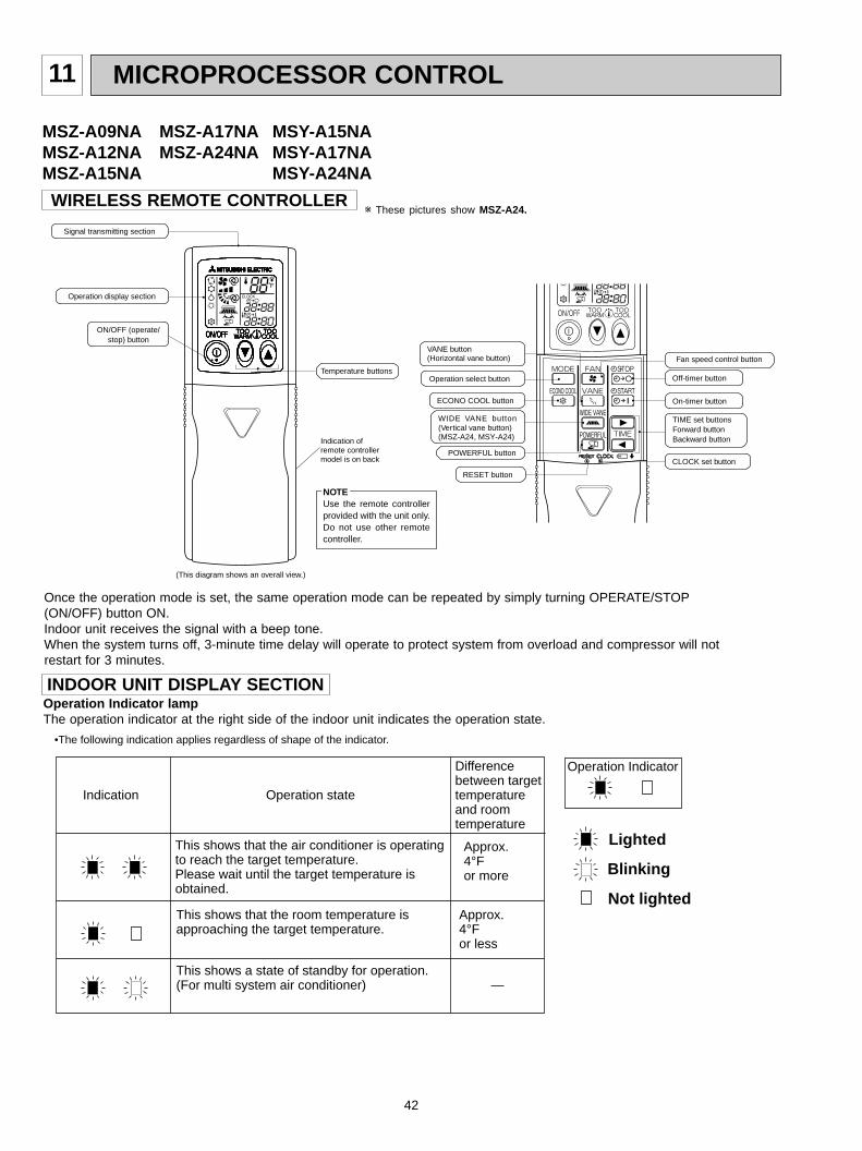
Once the operation mode is set, the same operation mode can be repeated by simply turning OPERATE/STOP(ON/OFF) button ON.Indoor unit receives the signal with a beep tone.When the system turns off, 3-minute time delay will operate to protect system from overload and compressor will notrestart for 3 minutes.
WIRELESS REMOTE CONTROLLER
(This diagram shows an overall view.)
Signal transmitting section
Operation display section
Temperature buttons
(This diagram shows an overall view.)
ON/OFF (operate/stop) button
NOTEUse the remote controllerprovided with the unit only.Do not use other remotecontroller.
Indication of remote controllermodel is on back
(This diagram shows an overall view.)
Fan speed control button
Operation select button
ECONO COOL button On-timer button
CLOCK set button
TIME set buttonsForward buttonBackward button
Off-timer button
RESET button
POWERFUL button
WIDE VANE button(V(MSZ-A24, MSY-A24)
ertical vane button)
VANE button(Horizontal vane button)
w These pictures show MSZ-A24.
MSZ-A09NA MSZ-A17NA MSY-A15NAMSZ-A12NA MSZ-A24NA MSY-A17NAMSZ-A15NA MSY-A24NA
Operation Indicator lampThe operation indicator at the right side of the indoor unit indicates the operation state.
Approx.4°F or more
Difference between targettemperature and room temperature
Approx.4°F or less
—
This shows that the air conditioner is operating to reach the target temperature.Please wait until the target temperature is obtained.
This shows that the room temperature is approaching the target temperature.
This shows a state of standby for operation.(For multi system air conditioner)
Operation stateIndication
Lighted
Blinking
•The following indication applies regardless of shape of the indicator.
Not lighted
Operation Indicator
INDOOR UNIT DISPLAY SECTION
OB450-2.qxp 06.11.29 1:40 PM Page 42

43
1. Coil frost preventionCoil frost prevention is as same as COOL mode. (11-1.1.)
2. Low outside temperature operationLow outside temperature operation is as same as COOL mode. (11-1.2.)
1. Cold air prevention controlWhen the compressor is not operating or is starting, and the temperature of indoor heat exchanger and/or the room temperature is low or when defrosting is being done, the indoor fan will stop or rotate in Very Low speed.
11-2. DRY ( ) OPERATION(1) Press OPERATE/STOP(ON/OFF) button.
OPERATION INDICATOR lamp of the indoor unit turns on with a beep tone.(2) Select DRY mode with OPERATION SELECT button.(3) The set temperature is determined from the initial room temperature.
11-3. HEAT ( ) OPERATION (MSZ)(1) Press OPERATE/STOP(ON/OFF) button.
OPERATION INDICATOR lamp of the indoor unit turns on with a beep tone.(2) Select HEAT mode with OPERATION SELECT button.(3) Press TEMPERATURE buttons (TOO WARM or TOO COOL button) to select the desired temperature.
The setting range is 61 ~ 88°F.
1. Coil frost preventionWhen the temperature of indoor heat exchanger becomes too low, the coil frost prevention mode works.The indoor fan operates at the set speed and the compressor stops. This mode continues until the temperature of indoorheat exchanger rises.
2. Low outside temperature operationWhen the outside temperature lowers during cool mode operation, low outside temperature operation starts, and theoutdoor fan slows or stops.
11-1. COOL ( ) OPERATION(1) Press OPERATE/STOP(ON/OFF) button.
OPERATION INDICATOR lamp of the indoor unit turns on with a beep tone.(2) Select COOL mode with OPERATION SELECT button.(3) Press TEMPERATURE buttons (TOO WARM or TOO COOL button)to select the desired temperature.
The setting range is 61 ~ 88°F.
2. High pressure protectionIn HEAT operation the compressor operational frequency is controlled by the temperature of the indoor heat exchanger toprevent the condensing pressure from increasing excessively.
3. DefrostingDefrosting starts when the temperature of outdoor heat exchanger becomes too low. The indoor/outdoor fans stop, the 4-way valve reverses, and the compressor starts. This mode continues until the temperature of outdoor heat exchanger rises or the fixed time passes.
11-4. FAN( d )OPERATION (MSY)(1) Press OPERATE/STOP(ON/OFF) button.
OPERATION INDICATOR lamp of the indoor unit turns ON with a beep tone.(2) Select FAN mode with OPERATION SELECT button.(3) Select the desired fan speed. When AUTO, it becomes Low.
Only indoor fan operates. Outdoor unit does not operate.
Mode
COOL mode of"I FEEL CONTROL"
DRY mode of"I FEEL CONTROL"
Initial room temperature
75°F or more
less than 75°F
11-5. “I FEEL CONTROL” ( ) OPERATION (MSY)(1) Press OPERATE/STOP (ON/OFF) button on the remote
controller. OPERATION INDICATOR lamp of the indoorunit turns on with a beep tone.
(2) Select “I FEEL CONTROL” mode with OPERATIONSELECT button.
(3) The operation mode is determined by the room tempera-ture at start-up of the operation.
• Once the mode is fixed, the mode does not change by room temperature afterwards.
• Under the ON-TIMER ( ) operation, mode is determined according to the room temperature at the set time theoperation starts.
OB450-2.qxp 06.11.29 1:40 PM Page 43

44
11-6. AUTO CHANGE OVER ··· AUTO MODE OPERATION (MSZ)Once desired temperature is set, unit operation is switched automatically between COOL and HEAT operation.
Mode selection(1) Initial mode
When unit starts the operation with AUTO operation from off;• If the room temperature is higher than the set temperature, operation starts in COOL mode.• If the room temperature is equal to or lower than the set temperature, operation starts in HEAT mode.
(2) Mode changeCOOL mode changes to HEAT mode when about 15 minutes have passed with the room temperature 4 degreesbelow the set temperature.HEAT mode changes to COOL mode when about 15 minutes have passed with the room temperature 4 degreesabove the set temperature.
NOTE: If two or more indoor units are operating in multi system, there might be a case that the indoor unit, which is operating in (AUTO), cannot change over to the other operating mode (COOL HEAT) and becomes a state of standby. Refer to 8-1. ”INFORMATION FOR MULTI SYSTEM AIR CONDITIONER”.
Model
COOL mode of"I FEEL CONTROL"
DRY mode of"I FEEL CONTROL"
Initial room temperature Initial set temperature
79°F or more
77°F to 79°F
less than 77°F
75°F
Initial room temperature
minus 4°FInitial room temperature
minus 4°F
❈ 1
(4) The initial set temperature is decided by the initial room temperature.
❈ 1 When the system is restarted with the remote controller, the system operates with the previous set temperature regard-less of room temperature at restart.The set temperature is calculated by the previous set temperature.
(5) TEMPERATURE buttonsIn “I FEEL CONTROL” ( ) mode, set temperature is decided by the microprocessor based on the room temperature.In addition, set temperature can be controlled by TOO WARM or TOO COOL buttons when you feel too cool or too warm.Each time the TOO WARM or TOO COOL button is pressed, the indoor unit receives the signal and emits a beep tone.
• Fuzzy controlWhen the TOO COOL or TOO WARM button is pressed, the microprocessor changes the set temperature, consideringthe room temperature, the frequency of pressing TOO COOL or TOO WARM button and the user’s preference to heat orcool. So this is called “Fuzzy control”, and works only in “I FEEL CONTROL” mode.In DRY mode of “I FEEL CONTROL”, the set temperature doesn’t change.
…To raise the set temperature 2~4 degrees (°F)
…To lower the set temperature 2~4 degrees (°F)
TOOCOOL
TOOWARM
OB450-2.qxp 06.11.29 1:40 PM Page 44

45
(3) PositioningThe vane is once pressed to the vane stopper to confirm the standard position and then set to the desired angle.Confirming of standard position is performed in the following cases.(a) When the operation starts or finishes (including timer operation).(b) When the test run starts.(c) When multi-standby starts or finishes.
11-7. AUTO VANE OPERATION1. Horizontal vane
(1) Vane motor driveThese models are equipped with a stepping motor for the horizontal vane. The rotating direction, speed, and angle ofthe motor are controlled by pulse signals (approximate 12V) transmitted from indoor microprocessor.
(2) The horizontal vane angle and mode change as follows by pressing VANE CONTROL button.
(4) VANE AUTO ( ) modeIn VANE AUTO mode, the microprocessor automatically determines the vane angle and operation to make the optimumroom-temperature distribution.
Upward
(1) In COOL and DRY operation
(2) In HEAT operation (MSZ)
MSZ-A09/12/15/17MSY-A15/17
MSZ-A24MSY-A24
Vane angle is fixed to Horizontal position or Angle 1.
Vane angle is fixed to Angle 4.
(6) Dew preventionDuring COOL or DRY operation with the vane angle at Angle 2 ~ 4 (A09 ~ 17) / Angle 3 ~ 5 (A24) when the compressorcumulative operation time exceeds 1 hour, the vane angle automatically changes to Angle 1 for dew prevention.
(5) STOP (operation OFF) and ON-TIMER standbyIn the following cases, the horizontal vane returns to the closed position.(a) When OPERATE/STOP (ON/OFF) button is pressed (POWER OFF).(b) When the operation is stopped by the emergency operation.(c) When ON-TIMER is ON standby.
NOTE: When 2 or more indoor units are operated with multi outdoor unit, even if any indoor unit turns thermostat off,this control doesn’t work in the indoor unit.
(8) Cold air prevention in HEAT operation (MSZ)The horizontal vane position is set to Upward.
(7) SWING MODE ( ) By selecting SWING mode with VANE CONTROL button, the horizontal vane swings vertically. The remote controller
displays “ ”.
OB450-2.qxp 06.11.29 1:40 PM Page 45
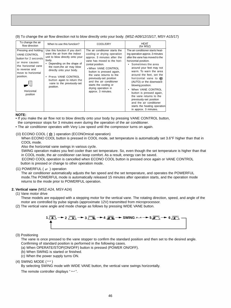
46
The air conditioner starts heat-ing operation approx. 3 minutesafter the vane has moved to thehorizontal position.• Sometimes the area
around your feet may notwarm. To warn the areaaround the feet, set thehorizontal vane to(AUTO) or the downward-blowing position.
• When VANE CONTROLbutton is pressed again, the vane returns to thepreviously-set positionand the air conditionerstarts the heating operation in approx. 3 minutes.
To change the airflow direction
When to use this function?
Use this function if you don’twant the air from the indoorunit to blow directly onto yourbody.• Depending on the shape of
the room,the air may blowdirectly onto your body.
• Press VANE CONTROL button again to return the
vane to the previously-set position.
The air conditioner starts thecooling or drying operationapprox. 3 minutes after thevane has moved to the hori-zontal position.
•
Pressing and holding
VANE CONTROL button for 2 seconds or more causes the horizontal vane to reverse and move to horizontal position.
COOL/DRY HEAT
NOTE:• If you make the air flow not to blow directly onto your body by pressing VANE CONTROL button,
the compressor stops for 3 minutes even during the operation of the air conditioner.• The air conditioner operates with Very Low speed until the compressor turns on again.
(9) To change the air flow direction not to blow directly onto your body. (MSZ-A09/12/15/17, MSY-A15/17)
Horizontalposition
When VANE CONTROLbutton is pressed again, the vane returns to thepreviously-set positionand the air conditionerstarts the cooling ordrying operation inapprox. 3 minutes.
(for MSZ)
(10) ECONO COOL ( ) operation (ECONOmical operation)When ECONO COOL button is pressed in COOL mode, set temperature is automatically set 3.6°F higher than that inCOOL mode.Also the horizontal vane swings in various cycle.SWING operation makes you feel cooler than set temperature. So, even though the set temperature is higher than thatin COOL mode, the air conditioner can keep comfort. As a result, energy can be saved.ECONO COOL operation is cancelled when ECONO COOL button is pressed once again or VANE CONTROL
button is pressed or change to other operation mode.
(11) POWERFUL ( ) operation The air conditioner automatically adjusts the fan speed and the set temperature, and operates the POWERFULmode.The POWERFUL mode is automatically released 15 minutes after operation starts, and the operation mode returns to the mode prior to POWERFUL operation.
61 2 3 4 5SWING
2. Vertical vane (MSZ-A24, MSY-A24)(1) Vane motor drive
These models are equipped with a stepping motor for the vertical vane. The rotating direction, speed, and angle of themotor are controlled by pulse signals (approximate 12V) transmitted from microprocessor.
(2) The vertical vane angle and mode change as follows by pressing WIDE VANE button.
(3) PositioningThe vane is once pressed to the vane stopper to confirm the standard position and then set to the desired angle.Confirming of standard position is performed in the following cases.(a) When OPERATE/STOP(ON/OFF) button is pressed (POWER ON/OFF).(b) When SWING is started or finished.(c) When the power supply turns ON.
(4) SWING MODE ( )By selecting SWING mode with WIDE VANE button, the vertical vane swings horizontally.
The remote controller displays “ ”.
OB450-2.qxp 06.11.29 1:40 PM Page 46

47
11-8. TIMER OPERATION1. How to set the time
(1) Press OPERATE/STOP (ON/OFF) button to start the air conditioner.(2) Check that the current time is set correctly.NOTE : Timer operation will not work without setting the current time. Initially “AM0:00” blinks at the current time display of
TIME MONITOR, so set the current time correctly with CLOCK SET button.
How to set the current time(1)Press the CLOCK set button.
(2)Press the TIME SET buttons ( and ) to set the current time.
• Each time FORWARD button ( ) is press, the set time increases by 1minute, and each time BACKWARD button
( ) is press, the set time decreases by 1minute.• Pressing thoes buttons longer increases / decreases the set time by 10 minutes.
Press the CLOCK set button.
ON timer setting(1) Press ON-TIMER button( ) during operation.
(2) Set the time of the timer using TIME SET buttons ( and ) . w
OFF timer setting(1) Press OFF-TIMER button ( ) during operation.
(2) Set the time of the timer using TIME SET buttons ( and ). w
w Each time FORWARD button ( ) is pressed, the set time increases by 10 minutes; each time BACKWARD button
( ) is pressed, the set time decreases by 10 minutes.
2. CancelTo cancel ON timer, press ON-TIMER button ( ).To cancel OFF timer, press OFF-TIMER button( ).TIMER is cancelled and the display of set time disappears.
START
STOP
START
STOP
(5) WIDE MODE ( )By selecting WIDE mode with WIDE VANE button, indoor fan speed becomes faster than setting fan speed on the
remote controller (W). The remote controller displays “ ”.
NOTE : The position of vane angle 3, angle 4 and angle 5 are different in COOL operation and HEAT operation.
W Indoor fan speed becomes faster than setting fan speed on the remote controller even when or isselected.
PROGRAM TIMER
(Example 1) The current time is 8:00 PM.The unit turns off at 11:00 PM, and on at 6:00 AM.
• OFF timer and ON timer can be used in combination. The timer of the set time that is reached first will operate first.• “ ” and “ ” display shows the order of OFF timer and ON timer operation.
(Example 2) The current time is 11:00 AM.The unit turns on at 5:00 PM, and off at 9:00 PM.
NOTE : If the main power is turned off or a power failure occurs while AUTO START/STOP timer is active, the timer settingis cancelled. As these models are equipped with an auto restart function, the air conditioner starts operating with
timer cancelled when power is restored.
OB450-2.qxp 06.11.29 1:40 PM Page 47
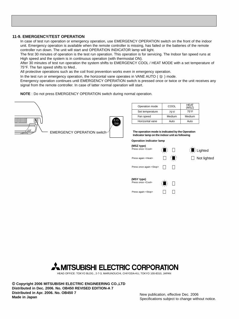
EMERGENCY OPERATION switch
E.O.SW
Operation mode COOL HEAT(MSZ)
Set temperature 75°F 75°F
Fan speed Medium Medium
Horizontal vane Auto Auto
The operation mode is indicated by the OperationIndicator lamp on the indoor unit as following
Operation indicator lamp
(MSZ type)
Press again <Heat>
Press once <Cool>
Press once again <Stop>
(MSY type)Press once <Cool>
Press again <Stop>
Not lighted
Lighted
11-9. EMERGENCY/TEST OPERATIONIn case of test run operation or emergency operation, use EMERGENCY OPERATION switch on the front of the indoorunit. Emergency operation is available when the remote controller is missing, has failed or the batteries of the remote controller run down. The unit will start and OPERATION INDICATOR lamp will light.The first 30 minutes of operation is the test run operation. This operation is for servicing. The Indoor fan speed runs atHigh speed and the system is in continuous operation (with thermostat ON).After 30 minutes of test run operation the system shifts to EMERGENCY COOL / HEAT MODE with a set temperature of75°F. The fan speed shifts to Med..All protective operations such as the coil frost prevention works even in emergency operation.In the test run or emergency operation, the horizontal vane operates in VANE AUTO ( ) mode.Emergency operation continues until EMERGENCY OPERATION switch is pressed once or twice or the unit receives anysignal from the remote controller. In case of latter normal operation will start.
NOTE : Do not press EMERGENCY OPERATION switch during normal operation.
HEAD OFFICE: TOKYO BLDG., 2-7-3, MARUNOUCHI, CHIYODA-KU, TOKYO 100-8310, JAPAN
CC Copyright 2006 MITSUBISHI ELECTRIC ENGINEERING CO.,LTDDistributed in Dec. 2006. No. OB450 REVISED EDITION-A 7Distributed in Apr. 2006. No. OB450 7Made in Japan
New publication, effective Dec. 2006Specifications subject to change without notice.
OB450-2.qxp 06.11.29 1:40 PM Page 48


