Embed Size (px)
Citation preview

MRK-D-0014, V1.0 Page | 1
Aeroqual Dust Sentry User Guide

MRK-D-0014, V1.0 Page | 2
Aeroqual Dust Sentry User Guide
Table of Contents
User Guide Revision History ............................................................................................................... 4
Description ..................................................................................................................................... 5 1.1. Nephelometer .......................................................................................................................... 6
1.1.1. Electrical connections to Nephelometer .......................................................................... 6 1.1.2. Inlet Heater ...................................................................................................................... 6 1.1.3. Inbuilt Filters .................................................................................................................... 6
1.2. Pump Module .......................................................................................................................... 7 1.3. Power Module ......................................................................................................................... 8 1.4. Auxiliary Module (Optional) ..................................................................................................... 8 1.5. Crevis PLC (Optional) ........................................................................................................... 10 1.6. Cellular IP GPRS modem (Optional) .................................................................................... 11 1.7. Electrical Connections ........................................................................................................... 11
Assembly and Installation .......................................................................................................... 12 2.1. Assembly of heated inlet ....................................................................................................... 12 2.2. Connect Mains Power ........................................................................................................... 13 2.3. Sample Collection Filter (Optional) ....................................................................................... 14
Connecting to the Dust Sentry .................................................................................................. 15 3.1. Initial Connection using Aeroqual Connect ........................................................................... 15 3.2. Connection Options ............................................................................................................... 16
Client Mode ................................................................................................................... 16 Cellular Network Connection ......................................................................................... 17
3.3. Aeroqual Cloud ..................................................................................................................... 18 3.4. Connection Scenarios ........................................................................................................... 20
Using Aeroqual Connect and Cloud ......................................................................................... 21 4.1. Journal ................................................................................................................................... 21 4.2. Manage Data ......................................................................................................................... 21
Charts ............................................................................................................................ 21 Table ............................................................................................................................. 22 Download Data .............................................................................................................. 22 Manual Sync .................................................................................................................. 22 Auto Export (Optional Extra) ......................................................................................... 23
4.3. Calibration and Service ......................................................................................................... 23 Gain and Offset ............................................................................................................. 23 Zero Calibration ............................................................................................................. 24
4.4. Diagnostics and Advanced .................................................................................................... 24 Diagnostics .................................................................................................................... 24 Module Settings............................................................................................................. 25
4.5. Configure Instrument ............................................................................................................. 25 Settings ......................................................................................................................... 25 Configuring the System ................................................................................................. 26 Configuring the Sensors ................................................................................................ 26 Configuring the PLC Output .......................................................................................... 26 PLC Output .................................................................................................................... 26 Sensor List .................................................................................................................... 27 Data filters ..................................................................................................................... 27 Alerts (Optional Extra) ................................................................................................... 28 About ............................................................................................................................. 28

MRK-D-0014, V1.0 Page | 3
Aeroqual Dust Sentry User Guide
Maintenance................................................................................................................................. 29 5.1. Maintenance Schedule .......................................................................................................... 29 5.2. Maintenance Procedures ...................................................................................................... 29
Sample Flow Adjustment .............................................................................................. 29 Zero Air Check (Purge Cycle) ....................................................................................... 30 Leak Check ................................................................................................................... 30 Manual Zero Air Check ................................................................................................. 31 Fibre Span Check.......................................................................................................... 31 Laser Current Check. .................................................................................................... 31 Filter Changes ............................................................................................................... 31 Cyclone and Inlet Cleaning ........................................................................................... 32
Mass Calibration ......................................................................................................................... 33
Troubleshooting .......................................................................................................................... 34
Specifications .............................................................................................................................. 36
Schematic Diagrams ................................................................................................................... 37 9.1. Pneumatics ............................................................................................................................ 37
Sample Mode ................................................................................................................ 37 Zero Mode ..................................................................................................................... 37
9.2. Electrical ................................................................................................................................ 38 9.3. Communication ..................................................................................................................... 38
Third Party Sensors .................................................................................................................... 39 10.1. Met One MSO ................................................................................................................... 39 10.1. Vaisala Weather Transmitter WXT520.............................................................................. 39 10.2. Gill WindSonic ................................................................................................................... 40 10.3. Cirrus MK427 Noise Sensor .............................................................................................. 40 10.4. Novalynx 240-200SZ Silicon Pyranometer ....................................................................... 40
Mounting and Site Positioning Guidelines ............................................................................... 41 11.1. Mounting ............................................................................................................................ 41 11.2. Inlet height ......................................................................................................................... 41 11.3. Measurement Interference ................................................................................................ 41 11.4. Safety ................................................................................................................................ 42
Appendix ...................................................................................................................................... 43 12.1. Warranty ............................................................................................................................ 43 12.2. Technical Support ............................................................................................................. 43 12.3. Declarations ...................................................................................................................... 43
12.4. Instrument Performance and Test Report………………………………………………….….44
12.5. Certificates……………………………………………………………………………………….45

MRK-D-0014, V1.0 Page | 4
Aeroqual Dust Sentry User Guide
User Guide Revision History
Document Number: MRK-D-0014
Product Version: 1.3
Description: User Guide for Dust Sentry
Date Revision number Description of change Affected pages
May 2015 V1.0 Initial Release All

MRK-D-0014, V1.0 Page | 5
Aeroqual Dust Sentry User Guide
Description
Aeroqual’s Dust Sentry is a user friendly instrument designed to provide reliable real time indicative
particulate measurement of TSP, PM10, PM2.5 or PM1 using a well proven near forward light
scattering nephelometer and high precision sharp cut cyclone.
The instrument includes an embedded PC and two powerful software systems, Aeroqual Connect
and Aeroqual Cloud. There are numerous additional options available, including wireless
communications, SMS and email notifications, alarm functionality and the integration of factory tested
weather sensors. The instrument is packaged in a robust, lockable enclosure and is light enough for
one person site installations. The ease of installation, as well as the extensive range of possible add-
ons, enables the unit to be used in a wide range of applications.
The key components of the Dust Sentry are described below.
Fuse Holder
Note: 12 VDC Power Supply mounted externally at base
Embedded
PC
Purge Filter
Modem
(Optional)
Din Rail Terminals
and PSU
termination
Pump Module
(Communications)
Sample Filter
Pump Module
(Pneumatics)
PM
Optical
Engine

MRK-D-0014, V1.0 Page | 6
Aeroqual Dust Sentry User Guide
1.1. Nephelometer Aeroqual uses a customised Nephelometer optical sensor from Met One Instruments. The optical
sensor uses light scattering from particulate matter to provide a continuous real-time measurement of
airborne particle mass. The light source is a visible laser diode and scattered light is measured in the
near forward angle using a focusing optics and a photo diode.
The Nephelometer has an on-board temperature sensor which corrects for thermal drift, sheath air
filter to keep the optics clean, automatic baseline drift correction and a fibre optic span system to
provide a check of the optical components.
1.1.1. Electrical connections to Nephelometer
The electrical connections to the Nephelometer are summarised below. These connections are
terminated in a 8 way molex connector:
Wire colour Function
Orange (x2) Fibre optic solenoid
Red 5V (power in)
Black Ground
White Signal out (0-5 V)
Black/white Signal Ground
Yellow Laser current monitor ( 10mV = 1 mA laser current)
Grey Temperature output
1.1.2. Inlet Heater
The Dust Sentry uses a 12 V heater on the sample inlet tube to reduce the humidity of sampled air to
prevent particle growth and fogging of the Nephelometer optics in high RH conditions. The inlet
should always be heated.
1.1.3. Inbuilt Filters
The Nephelometer contains two filters which should be replaced at specified intervals (see
Maintenance Section 5). The “Sample” filter is a coarse filter designed to protect the sample pump
from excessive particle build-up. The “Purge” filter is a fine filter which filters the sheath air flow and
also produces particle-free air during the auto-zero cycle.
Safety: This sensor is considered a Class I laser product. Class I laser products are not
considered to be hazardous. There are no user serviceable parts inside the cover of
the sensor. The device contains a laser operating at 670 nm which is visible to the eye
and can cause damage to the eye if directly exposed. Only trained service personnel
should attempt servicing or repair of the sensor.

MRK-D-0014, V1.0 Page | 7
Aeroqual Dust Sentry User Guide
1.2. Pump Module
The Pump Module is split into two sections:
1. The electronics
2. The pump and pneumatics
The functionality of the electronics module can be seen below:
Note: The jumpers in the module should be positioned as shown in the image above.
The pump and pneumatics are easy to access for servicing and replacement:
Status LED
12VDC Power
Connectors
RJ45 Connectors for
RS485 bus
Connection
80180 engine
PM Fibre Span Switch
Inlet Heater
Connection to
Purge Pump
Connection to
Sample Pump
Pin 1 = 12V (blue)
Pin 2 = GND (white) Purge Pump
Pin 3 = 12V (red)
Pin 4 = GND (black) Sample Pump
Purge
Pump
Sample Pump
Exhaust Line
Sheath
Air Out
Sample In
Connection to
electronics module
(Pin 1 to 4)
Jumpers

MRK-D-0014, V1.0 Page | 8
Aeroqual Dust Sentry User Guide
1.3. Power Module
The Dust Sentry internal power requires regulated 12 VDC to
maintain a constant pump speed. An external mains to
12VDC power supply (Meanwell HLG80-12A 60W 12V) is
fitted on the outside of the enclosure and this will allow
connection to mains supply.
Note: If you wish to run the Dust Sentry on solar power you will need to use a DC-DC convertor
in order to supply a regulated 12 VDC for the Dust Sentry
1.4. Auxiliary Module (Optional)
The auxiliary module acts as an interface between third party sensors and the Dust Sentry
communication bus. It is configured with different operating modes which can be selected by using
the dipswitches located on the side of the module. Aeroqual has integrated a number of third party
sensors and is able to supply the auxiliary module preconfigured for your sensors.
The tables below list the various functions:
Firmware: AUX_MODULE_01.
Use for: Analogue inputs, Vaisala WXT520 weather, Gill Windsonic wind, Cirrus MK:427 noise.
1 2 3 4 Function
OFF OFF OFF OFF Default - standard Auxiliary module with AN1, AN2, Freq
ON OFF OFF OFF Vaisala WXT520 with RS232 communication + AN1, AN2, Freq
OFF ON OFF OFF Vaisala WXT520 with RS232 communication + Cirrus MK427 Noise
ON ON OFF OFF Wind Sonic with RS232 communication + AN1, AN2, Freq
OFF OFF ON OFF Wind Sonic with RS232 communication + Cirrus MK427 Noise
ON OFF ON OFF Cirrus MK427 Noise module only
Programming Dip
Switch
Programming
Port

MRK-D-0014, V1.0 Page | 9
Aeroqual Dust Sentry User Guide
Firmware: AUX_MODULE_02.
Use for: Analogue inputs, Met One MSO weather, Met One 034b wind, Cirrus MK:427 noise.
1 2 3 4 Function
OFF OFF OFF OFF Default - standard Auxiliary module with AN1, AN2, Freq
ON OFF ON OFF Cirrus MK427 Noise module only
OFF ON ON OFF Met One MSO with RS232 communication + Cirrus MK427 Noise
ON ON ON OFF Met One MSO with RS232 communication + AN1, AN2, Freq
OFF OFF OFF ON Met One 034B analogue module + Cirrus MK427 Noise
The third party sensor needs to be correctly wired into the auxiliary module for it to function correctly.
The image and table below provide further information on wiring the auxiliary module.
Example of wiring:
Wind Sonic (Pin 1) GND,
SIGNAL GND (Pin 2) 12V (Pin 5) RX (Pin 6) TX
Vaisala
(Pin 1) GND for
operating, data &
heating
(Pin 2) 12V for
operating & heating (Pin 5) RX (Pin 6) TX
Met One MSO
(Pin 1) GND,
SIGNAL,
COMMON, SHIELD
(Pin 2) 12V (Pin 5) RX (Pin 6) TX
Met One 034B (Pin 1) GND (Pin 11) METONE
034B PWR (Pin7) WD (Pin 9) WS
Cirrus MK:427 (Pin 1) GND,
ACTUATOR GND
(Pin 2) 12V, LOOP
IN (Pin 8) LOOP OUT
(Pin 12)
ACTUATOR IN
Pin 12
Pin 1
Status LED
12VDC Power
Connectors
RJ45 Connectors
for RS485 bus
Wiring of Aux Module:
PIN 1: GND
PIN 2: 12V FUSED
PIN 3: RESERVED
PIN 4: RESERVED
PIN 5: RX
PIN 6: TX
PIN 7: 0-5V IN
PIN 8: 4-20mA IN
PIN 9: FREQ IN
PIN 10: AGND
PIN 11: METONE 034B PWR
PIN 12: CIRRUS ACTUATOR

MRK-D-0014, V1.0 Page | 10
Aeroqual Dust Sentry User Guide
A programming port is also exposed through the side of the module to allow custom programs to be
loaded into the module.
Note 1: Aeroqual can supply a standard programming tool for approved technicians to
reprogram the auxiliary module to the specified requirements.
Note 2: The above wiring connections are subject to change, please refer to the third party
sensor manuals for the latest wiring instructions.
Note 3: If a Novalynx 240-200SZ Pyranometer is purchased the Auxiliary module will be
preconfigured for this sensor. Pin 2 (12V) and Pin 8 (4-20mA IN) need to be wired in.
1.5. Crevis PLC (Optional)
The Dust Sentry can be configured with a Crevis controller and
Crevis output cards. These output cards are designed to convert
the Dust Sentry’s digital values to analogue outputs. The cards
offer 4 x 4-20mA and 2 x relay outputs which can be user
configured in Aeroqual Connect or Aeroqual Cloud.
The Crevis controller type is Modbus NA-9171 and the mode type
is Modbus RTU. The outputs cards are ST-4214 for the 4-20mA
outputs and ST-2747 for the relay outputs. Further information
and specification on both these cards can be found on the USB
stick provided with the instrument.
The Crevis is powered by the Dust Sentry 12V power supply. As a
result the maximum load is 300ohms. If a higher maximum load is
required an external 24V power supply can be used to power the
Crevis. This will allow for a maximum load of at least 500ohms.
Wiring instructions can be found below. There are several glands
located at the base of the Dust Sentry which can be used to wire
an external device.
Wiring the 4-20mA output card
12V Power In

MRK-D-0014, V1.0 Page | 11
Aeroqual Dust Sentry User Guide
Wiring the relay output card
Note 1: The AC power option will not work on the Dust Sentry. The maximum voltage is 24VDC
Note 2: The default relay setting is Normally Open
Note 3: The default 4-20mA setting is to report 4mA. If this option is disabled it will continue to
read 4mA.
Note 4: Please see Section 4.5.5. for information on configuring the set points and channels.
1.6. Cellular IP GPRS modem (Optional)
The Moxa G3111 Modem is a compact quad-band GPRS IP gateway which
allows connection of the Dust Sentry to a cellular network. The modem is
preconfigured to work alongside the embedded PC installed in the instrument
and is set up with a virtual server to allow direct connection to Aeroqual
Connect. If required, a DynDNS can also be created for direct connection to
Aeroqual Connect on a public dynamic IP address.
Note: See Section 3.2.2. for more information on configuring the modem.
1.7. Electrical Connections
RS485 Bus
The two wire RS485 bus connections are made using 20 cm CAT5 cables between the sensor
modules.
12 VDC Power Bus
All modules inside the Dust Sentry operate from the 12VDC power. The power is supplied by a daisy
chain of black and red cables. To turn off the 12VDC power to the Dust Sentry, release the fuse
holder.
12 VDC Power in
12 VDC power is connected into the instrument at the din rail terminals.

MRK-D-0014, V1.0 Page | 12
Aeroqual Dust Sentry User Guide
Assembly and Installation
2.1. Assembly of heated inlet
Parts List:
A. Inlet Tube/Heater including power cable
B. Sharp Cut Cyclone (if fitted)
C. TSP Inlet
i. Connect parts A, B and C
ii. Open door of enclosure and remove protective cap from the optical engine
iii. Insert Inlet Tube Assembly through base mount and fix the three mounting screws
Note 1: Make sure the O-Ring is fitted before connecting the inlet tube assembly. The O-Ring
should be lubricated to reduce wear and tear. Lubricant is provided in the Dust Monitor
Service Kit.
Note 2: Ensure the power cable is fed through the inlet hole when connecting in inlet tube.
O-Ring
A B C
Protective
Cap
3x M3 Mounting
Screws

MRK-D-0014, V1.0 Page | 13
Aeroqual Dust Sentry User Guide
iv. Connect power to Inlet Tube/Heater inside the enclosure
2.2. Connect Mains Power
1. Locate the power connector terminal which is situated outside the enclosure at the bottom.
The power supply will already be wired to the connector however the cable to connect to
mains power needs to be wired.
Caution: The high voltage mains supply must be wired by a certified electrician in
compliance with local electrical regulations.
3. Reconnect into the connector
ensuring the plugs are fitted securely
and the nut gland tightened.
Plug
Nut gland
Connector
Terminal block
Neutral
(Blue)
Earth
(Yellow/Green)
Live
(Brown)
2. Feed the power cable through the nut gland
plugs and connector and wire the cable to the
terminal block according to the diagram.
Note: To remove the terminal block from inside the connector unclick it from the casing by
turning it slightly then pull out
1. Unscrew the nut
gland to loosen the
terminal block and pull
connector apart
Power cable from
heated inlet

MRK-D-0014, V1.0 Page | 14
Aeroqual Dust Sentry User Guide
2.3. Sample Collection Filter (Optional)
The Dust Sentry can be fitted with a 47mm collection filter holder if requested. It is used to collect
particulate samples for composition analysis.
Note: If the Dust Sentry is shipped with a sample collection filter holder, it
will not contain a filter on arrival. The filter will be packed separately in the
accessories box.
If you wish to use the sample collection filter:
1. Remove the internal sample filter from the 80180 optical engine (See
Section 5.2.7.)
2. Unscrew the collection filter housing, remove the black gasket and
insert a 47 mm filter.
Note: When the filter holder is not being used make sure the gasket is fitted to
reduce potential for leaks.
3. Tighten the collection filter housing using the wrench provided.
4. Check and adjust the sample flow to 2.0 LPM (See Section 5.2.1.)
The sample collection filter must be changed at regular intervals to avoid the filter blocking and
overloading the pump.
Instrument type Elevated PM levels Typical PM levels
Dust Sentry PM10 or TSP 1 week 2 weeks
Dust Sentry PM1 or PM2.5 2 weeks 4 weeks
Note: These are recommended maximum timeframes

MRK-D-0014, V1.0 Page | 15
Aeroqual Dust Sentry User Guide
Connecting to the Dust Sentry
3.1. Initial Connection using Aeroqual Connect
Aeroqual Connect is the instrument operating software which comes with the Dust Sentry and allows
the user to be connected directly to the instrument. It can be accessed via WIFI, Ethernet or a cellular
modem. The on-board computer has an Ethernet output for direct wired connection. Alternatively,
connection can be made over WIFI by connecting to the Dust Sentry network (Access point mode), a
local network (Client mode) or via a modem.
The default setting of the instrument when first purchased will be to connect to Aeroqual Connect via
access point mode. Access point mode allows connection to the Dust Sentry via the Dust Sentry
network signal which will show up on a laptop, tablet or smart phone within range. This type of
connection will most commonly be used when working on the instrument in the field. However, it will
also be used to initially connect when the instrument first arrives.
Connecting by this mode will mean the user’s device is connected via WIFI directly to the Dust Sentry.
There will be no internet connection on the user device when using this option. To connect you will
need to select the Dust Sentry WIFI network and enter the password.
Note: The default user name and passwords can be found on Page 1 of the log book.
Once a WIFI connection has been made Aeroqual Connect can be accessed via the PC browser by
entering the IP address 10.10.0.1 in the address bar. The login screen below will then be displayed.

MRK-D-0014, V1.0 Page | 16
Aeroqual Dust Sentry User Guide
1. An Aeroqual Connect login name and password will be provided when Aeroqual Connect is
first purchased. If you do not know your login details please contact [email protected].
2. Once you have logged in the homepage will be displayed.
Note 1: Different applications will appear depending on the user accessibility configured for
your account.
Once the first connection has been made (via access point mode) the WIFI communications can be
configured according to how you would like the system to respond. This can be done via the settings
tab under the Configure Instrument application.
3.2. Connection Options
Client Mode
Client mode allows connection to the Dust Sentry via a local network (e.g. your office network). If
there is a local WIFI or LAN network available at the Dust Sentry installation site then the instrument
can be set up to connect to this network. This might be the case if the Dust Sentry is installed on the
perimeter of an industrial site and the WIFI network extends out to where the unit is installed.
Alternatively the Dust Sentry can be connected to the local network via an Ethernet cable from the
instrument to the local router using the Ethernet output on the base of the Dust Sentry.
When the Dust Sentry is connected to your local network (such as your office WIFI network), the local
network will automatically assign a local IP address to the instrument. The IP address assigned to the
instrument can be found in the Configure Instrument application when logged in via Aeroqual Cloud.
Entering this IP address into the web browser will open Aeroqual Connect for that specific instrument,
assuming you are within the local network.
If the local network allows outside access (e.g. via VPN), connection to the Dust Sentry can be made
from anywhere in the world. In the more common scenario where the local network does not permit
outside access you may still connect to the Dust Sentry using Aeroqual Cloud through the internet
because most local networks permit internet access.
To configure the Dust Sentry to use client mode the instrument needs to be configured via the
settings tab under the Configure Instrument application.
1. The WIFI mode needs to be set to Client
2. The WIFI SSID (local network name) needs to be entered (e.g. your office WIFI name)
3. The WIFI password needs to be entered (e.g. the password for your office WIFI)
Note 1: Before changing the WIFI settings it is recommended that you have another
connection to the instrument established – typically by connecting the instrument to your LAN
using the Ethernet connection and using Connect with the LAN IP address.
Note 2: Once WIFI client mode is set up Aeroqual Connect will automatically disconnect from
WIFI access point mode. Connection will then need to be made via Aeroqual Cloud (See
section 4.5) to see the local IP address assigned to the instrument.
Note 3: If the local WIFI network password changes or you enter it incorrectly, you could be
locked out of the Dust Sentry. If this happens you will need to re-set the Dust Sentry back to
factory default settings, which puts the Dust Sentry back in to Access Point mode with a
default password. You can then reconfigure the settings correctly. Contact
[email protected] for information on how to perform this process.

MRK-D-0014, V1.0 Page | 17
Aeroqual Dust Sentry User Guide
Cellular Network Connection
If the Dust Sentry has an IP modem installed in the instrument a connection can be made via a
cellular network. This option is useful when remote access to the Dust Sentry is required but there is
no local network signal at the instrument installation site so client mode cannot be used. Aeroqual will
preconfigure the modem and load a default APN (Internet). This may work without having to be
changed. If set up is still required, only the APN, User name and Password needs to be modified.
Note 1: A local data telecommunications contract and SIM card is required.
Note 2: The Dust Sentry uses approximately 20 megabytes per sensor per day. This is an
estimate for a Cloud connection and can vary wildly depending on the cellular provider.
Note 3: Using Aeroqual Connect via the modem will incur higher data usage.
1. The IP modem can be set up by plugging directly from the modem Ethernet port to a laptop
Ethernet port and browsing to 192.168.127.254.
2. In the menu select Network Settings GSM GPRS Settings and configure settings as per
picture below. Contact your SIM card provider to obtain full ATD and APN settings. Click
Submit button.
3. Unplug MOXA unit from the network and plug it into Dust Sentry embedded PC. Restart Dust
Sentry embedded PC and modem.
4. In the Configure Instrument application the Ethernet Mode setting needs to be set to Auto
(DHCP). WIFI mode should still be set to Access Point so a direct connection can still be
made.
5. If you do not wish to use Aeroqual Cloud a public static IP or a DynDNS service will need to
be set up to create a permanent web address for the Dust Sentry.
6. A Dyn account can be created at https://account.dyn.com/cart/?via=upgrade-now
7. Log in to your account and add a new host name:

MRK-D-0014, V1.0 Page | 18
Aeroqual Dust Sentry User Guide
8. Go back to MOXA modem configuration interface, and choose System Management - > Misc.
Network Settings - > DDNS. Select enable and DynDns.org. Input the host name created in
Dyn account, user name and password as well for the Dyn account. Then click Submit button,
Save and Restart. Now the modem should be ready to be connected via host name.
9. Enter the set up web address into the web browser to access Aeroqual Connect.
Note 1: No data is stored on the DynDNS server. It only acts as an access point to
communicate with the Dust Sentry.
Note 2: In some countries the telecommunications provider will block incoming requests to
the modem. If this is the case DynDns will not work with regular SIM cards. Contact your
telecommunications company about using an open APN or use a private APN.
3.3. Aeroqual Cloud When using Aeroqual Cloud, the user is connected to the Aeroqual Cloud server. The Dust Sentry
instrument is also connected to the Cloud server. The user connects to Cloud over the internet; the
Dust Sentry is connected to the Cloud server using WIFI, Ethernet or Cellular (modem required).
Aeroqual Cloud is a website.

MRK-D-0014, V1.0 Page | 19
Aeroqual Dust Sentry User Guide
Aeroqual Cloud allows management of either a single Dust Sentry unit or a network of Dust Sentry
units by using any internet-enabled browser.
Aeroqual Cloud has all of the control features of Aeroqual Connect. The additional benefits of having
Aeroqual Cloud include:
View and manage a network of instruments
Remotely update instrument firmware
Advanced user access management
Enjoy faster browsing speeds
Minimise data usage costs
Back up data so it can never be lost
Access data even when the instrument is offline
Send SMS/text and email alerts (optional)
Auto export data via FTP to another server (optional)
Auto export a data file via email (optional)
As a user, you simply access Aeroqual cloud through the internet; Aeroqual Cloud is a website which
provides total control over your Dust Sentry. You will need to go to http://cloud.aeroqual.com and
enter your login name and password.
Note 1: If you do not know your login name and password please contact
As well as having access to all the features available in Aeroqual Connect, Aeroqual Cloud can be
used to manage a network of Dust Sentrys. Depending on the user accessibility configured to your
account, Dust Sentry units can be managed by Organisations and Networks. This feature is available
in the Administration application.
The Dust Sentry must have internet access for you to see it and control it using the Cloud website.
For the Dust Sentry to have internet access it must be either in Client mode, as described above, and
be on a network which permits internet access (most networks do permit internet access). A modem
is not required in this situation.
Organisations Networks Instruments

MRK-D-0014, V1.0 Page | 20
Aeroqual Dust Sentry User Guide
Or if a local network is not available, the Dust Sentry must have an IP modem installed and a SIM
card and data contract with a local telecommunications provider.
3.4. Connection Scenarios
There are a number of ways to connect to the Dust Sentry instrument using Aeroqual Connect or
Aeroqual Cloud. To help clarify which connection should be used please refer to the tables below
which shows the 4 most common scenarios.
Dust Sentry
Location
User
Location Recommended Connection
Office Office
The Dust Sentry should be connected to the office WIFI network
using client mode. You can then connect using Aeroqual Cloud.
Aeroqual technicians will also be able to connect using Aeroqual
Cloud if support is required. A wired Ethernet connection can also be
made from the Dust Sentry direct to the local router.
In the field and
modem is installed Office
If the Dust Sentry is on a 3G network permanently you can connect
using Aeroqual Cloud from your office at any time.
In the field and
modem is installed At site
If you are in the field with the Dust Sentry, you can connect directly to
the instrument via Aeroqual Connect using the Dust Sentry as an
access point
In the field and no
modem installed At site
If you are in the field with the Dust Sentry and there is no 3G
available you can connect as an access point while in the field. Use
manual sync to upload data to Aeroqual Cloud when back in the
office and WIFI is available.
If you are not using Aeroqual Cloud there are 3 options:
Dust Sentry Location User Location Recommended Connection
In the field and modem
is installed Office
If the Dust Sentry is on a 3G network permanently use a
DYDNS service to connect directly to the instrument via
Aeroqual Connect.
In the field and modem
is installed At site
If you are in the field with the Dust Sentry, you can connect
directly to the instrument via Aeroqual Connect using the Dust
Sentry as an access point
In the field At site If there is no 3G available you can only connect to the Dust
Sentry using WIFI access point whilst on site.
Aeroqual Connect is the lead system. If both the Aeroqual Connect and Cloud systems are
being run simultaneously, any changes made in Aeroqual Connect will override the
changes made in Aeroqual Cloud.

MRK-D-0014, V1.0 Page | 21
Aeroqual Dust Sentry User Guide
Using Aeroqual Connect and Cloud Aeroqual Connect and Cloud have a range of applications available which allow the user to access
data, assess performance, schedule calibrations and diagnose faults remotely.
4.1. Journal The journal can be accessed by selecting Journal on the menu bar located at the top of the screen. It
is used to log when any changes are made to the Dust Sentry. The journal is searchable by date
using the side bar and filtered via the drop down menu.
The filter allows entries to be searched by:
User Entry – Manually entered journal entries
Calibration – Changes associated to calibration e.g. gain and offset modifications and
notification when service actions start and stop
Configuration – Changes made to the Dust Sentry configuration e.g. sensor added or
communications altered
Module Settings – Changes made to the sensor module settings
System changes – Notifies when the Dust Sentry starts up, shuts down or is rebooted
Note 1: To manually create a journal entry select “Add user entry”, type in the relevant
information and press save.
Note 2: Service mode is initiated by starting “Manual Service Mode” in the Calibration and Service application. A journal entry will be automatically generated when the service is started and stopped.
4.2. Manage Data
The manage data application allows the user to view the data either as a chart or in a table. There is
the option to view the raw or averaged data as well as the ability to filter the data to show specific time
periods. The data can also be exported for further analysis within this application.
Charts
To view the data in graphical format select the “Charts” option.
The charts can be configured to view a specific time period using the “From” and “To” dates
shown at the top of the screen.
An averaging period can also be selected from the drop down menu
Note: The minimum average period is determined by the date range

MRK-D-0014, V1.0 Page | 22
Aeroqual Dust Sentry User Guide
Table
To view the data in a table select the “Table” option.
The data can be configured to view a specific time period using the “From” and “To” dates
shown at the top of the screen.
The data can also be filtered using the “Averaging Period” drop down menu.
Note 1: The minimum average period is determined by the date range
Note 2: Depending on the administration rights, raw data can also be viewed. This is 1 minute
data without data filtering in place
Download Data
Data can be downloaded by selecting “Download Data”.
A specific data set can be chosen for download by using the “From” and “To” date selection.
The Journal can also be downloaded if required.
Note: The data will be downloaded in csv. format
Manual Sync
If the Dust Sentry is outside of cellular and WIFI range, the Dust Sentry data can always be
downloaded to your device using a WIFI access point (see Section 3.1.) when at the instrument site.
The data will be downloaded to an unreadable file and will include all information stored on the Dust
Sentry on-board PC. The file can then be uploaded onto Aeroqual Cloud, once a WIFI or cellular
network is available, to view the data from the unit, including diagnostics and settings.

MRK-D-0014, V1.0 Page | 23
Aeroqual Dust Sentry User Guide
To download the data: In Aeroqual Connect select Manual Sync in the Manage Data application.
Here it will prompt you to select a location on your PC to download the data to.
To upload the data: In Aeroqual Cloud select Manual Sync in the Manage Data application. Here it
will prompt you to upload the file which was previously downloaded from Aeroqual Connect.
Note: If there is a lot of data to download from Aeroqual Connect multiple manual syncs may
need to be performed. The date in the manual sync function updates showing how much data
has been downloaded.
Auto Export (Optional Extra)
The auto export option allows the data to be automatically exported to either a selected email address
or to an FTP server. To set either of these features up they need to be enabled by selecting the
enable check box under the auto export option.
Email: To enable auto export to a specific email the frequency, format and averaging period needs to
be selected. There is also the option to include the journal in the export. Make sure a correct email
address is entered and save the changes for it to take effect.
FTP: To enable auto export to a FTP server the frequency, format and averaging period needs to be
selected. There is also the option to include the journal in the export. The FTP server, user name and
password also need to be entered correctly. Save the changes for it to take effect.
Note: The journal captures any error messages; these are particularly useful for
troubleshooting.
4.3. Calibration and Service The calibration and service application allows the user to perform manual adjustments to the gain and
offset settings for the nephelometer.
Gain and Offset
Selecting the “Gain and Offset” menu will display the gain and offsets for all the configured
PM sizes in the Dust Sentry. Between 5 and 50 real time measurements will also be
displayed, as well as the average and standard deviation for the shown readings. These
numbers will automatically update.

MRK-D-0014, V1.0 Page | 24
Aeroqual Dust Sentry User Guide
Prior to any manual calibration or servicing activities the “Manual Service Mode” button
should be started. This will ensure the raw data is highlighted and labelled appropriately to
show that a service is being performed. This is particularly helpful to alert when a calibration
has taken place to ensure the readings are disregarded from any future data analysis.
Note 1: Any flagged data is disregarded when calculating averaged readings.
Note 2: Remember to stop the “Manual Service Mode” after the service has been completed to
ensure future reported data is tagged as “Sample” data.
Note 3: The Manual Service Mode will automatically stop after 24 hours if left running.
The calibration parameters can be adjusted manually by clicking the setting that requires
changing, entering the new value and pressing save.
Zero Calibration
Selecting the zero calibration menu will give you the option to manually start the purge cycle. The
purge cycle is designed to pump air backwards through the optical engine as a cleaning mechanism.
For more information on performing a manual zero check please see Section 5.2.2.
Note: The Dust Sentry will perform an automatic zero calibration every 12 hours.
4.4. Diagnostics and Advanced The diagnostics and advanced application allows the user to view the sensor module settings as well
as the sensor diagnostics. This information is useful when fault diagnosing an issue with a module.
The diagnostic data can be exported for further analysis and the sensor module settings can be
updated or modified in this application.
Diagnostics
The diagnostics view will display the diagnostics for the selected parameter. The data can be
paused or exported using the buttons above the table.
40 minutes of data will be displayed at a time and the data will automatically update unless
the pause button is pressed.

MRK-D-0014, V1.0 Page | 25
Aeroqual Dust Sentry User Guide
Module Settings
The module settings view will show the individual module settings and version number for all the
parameters configured inside the Dust Sentry.
The module settings can be changed by selecting the value that needs changing, entering the
new value and clicking save.
Note: Incorrect modification of module settings may cause irreversible damage. Do not change
settings without contacting Aeroqual or a qualified service agent.
4.5. Configure Instrument The configure instrument application stores all the configuration settings relevant for the specific Dust
Sentry connected. Depending on the user type different features will be accessible. The application
can also be used to view a complete sensor list for all parameters that have been configured on the
Dust Sentry, filter data and set up SMS and email alerts if this function has been purchased.
Settings
The settings tab is split into 5 columns which display different information relevant to the Dust Sentry.

MRK-D-0014, V1.0 Page | 26
Aeroqual Dust Sentry User Guide
Configuring the System
The serial number is listed here. It cannot be changed and is also shown on the
log book and inside the Dust Sentry enclosure.
The name of the instrument can be set by the user, for example, to reflect the
location or customer that is running the Dust Sentry
The device, software version and time last contact was made with the cloud
server is listed here for reference.
The time zone of the Dust Sentry can be set here to display the correct date for
the region the instrument is installed in.
The default averaging period can be configured here. Data can be configured to
read from 1 minute to daily averages.
Service time out can be set here. This is important if the manual service mode is
left on by accident. The time out value will stop manual service mode after the
time period set.
The restart instrument checkbox will force a restart of the embedded PC. The
checkbox will be cleared automatically after restart.
Configuring the Sensors
The default unit of measurement for PM is µg/m3.
The poll interval and poll time out functions will control how often the embedded
PC polls the modules. This should not be changed.
The active sensors will be displayed here. If a module has been added the
sensor will need to be selected from the drop down menu and added to the active
sensors list. Sensors can also be removed by clicking on the sensor name.
Configuring the PLC Output
v. If a Crevis is installed in the Dust Sentry the 4-20mA output module and relay
output module options should be check marked.
vi. The baud rate and COM port used will also be shown here. These settings
should not be changed.
Note 1: For information on the communications section please see Section 3.
Note 2: For information on the legacy section please contact Aeroqual.
PLC Output
The 4-20mA and relay output modules can be configured here. There are four 4-20mA output
channels available which can be set to read a user defined parameter and range. The relay output
module has two relay options that can also be user configured. The parameter, set point and reset
point can be added here. The relays can be configured as either rising or falling edge triggers.
If the set point is exceeded the relay is activated. This can be used to activate a siren or strobe or
other peripheral devices. The relay remains activated until the measured value drops below or
reaches above the reset point.
Rising Edge: Relay is energised when the concentration reaches above the set point and stays on
until the concentration drops below the reset point, which is set at a lower concentration than the set
point.
Falling Edge: Relay is energised when the concentration is below the set point and stays on until the
concentration reaches above the reset point, which is set at a higher concentration than the set point.
The relay will remain off until the concentration drops down below the set point.

MRK-D-0014, V1.0 Page | 27
Aeroqual Dust Sentry User Guide
Note: Please see Section 1.5 for more information on the Crevis PLC
Sensor List
The sensor list tab displays all the sensors that can be configured into the Dust Sentry. The table is
mainly for reference and shows all the settings configured for each sensor e.g. the units and
conversion factors. If a new sensor list is released it can be imported in this section.
Data filters
The negative number filter can be turned on for specific
parameters in this section. If you do not want the data to
show negative numbers for certain parameters, check the
checkbox of that specific parameter. Any negative numbers
reported will now show as zero.
Note: The negative number filter is NOT applied to RAW
readings. It is applied to all averaged readings.

MRK-D-0014, V1.0 Page | 28
Aeroqual Dust Sentry User Guide
Alerts (Optional Extra)
SMS and email alerts can be set up in this section. Alerts
can be set to notify when:
1. a concentration exceeds the user defined set point
2. a sensor fails
3. the Dust Sentry is in operation mode
4. the Dust Sentry goes offline
Note 1: Operation mode allows alerts to be sent when
the mode changes. For example, if the unit changes
from normal mode to zero calibration, or manual service
mode an alert is triggered. An alert will also be sent
when the unit returns to normal mode.
An email address and/or SMS number needs to be entered into the relevant fields to allow the alerts
to be sent. Multiple alerts can be set up by pressing the Add a new alert button.
Note 2: Phone numbers need to be in the format +64234566 with no spaces. A space is treated
as a separate phone number.
Note 3: SMS alert allowance is 50 per month. If two phone numbers are entered in a single alert
it counts as 2 messages.
About
The about screen shows information regarding your
Aeroqual Cloud license. It shows:
Instrument Type
Version
Licence Type
Last Contact
SMS Alerts Remaining
SMS Montly Allowance Roll Over Date
MRK-D-0014, V1.0 Page | 29
Aeroqual Dust Sentry User Guide
Maintenance
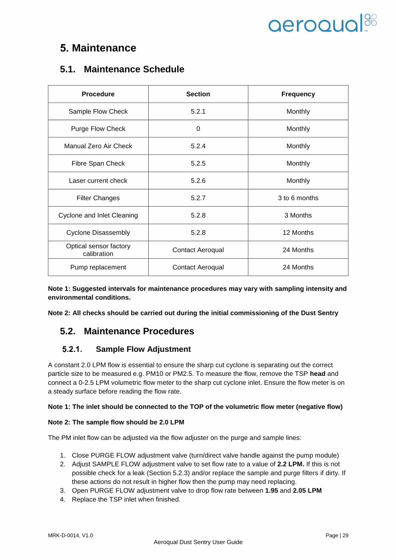
5.1. Maintenance Schedule
Procedure Section Frequency
Sample Flow Check 5.2.1 Monthly
Purge Flow Check 0 Monthly
Manual Zero Air Check 5.2.4 Monthly
Fibre Span Check 5.2.5 Monthly
Laser current check 5.2.6 Monthly
Filter Changes 5.2.7 3 to 6 months
Cyclone and Inlet Cleaning 5.2.8 3 Months
Cyclone Disassembly 5.2.8 12 Months
Optical sensor factory calibration
Contact Aeroqual 24 Months
Pump replacement Contact Aeroqual 24 Months
Note 1: Suggested intervals for maintenance procedures may vary with sampling intensity and
environmental conditions.
Note 2: All checks should be carried out during the initial commissioning of the Dust Sentry
5.2. Maintenance Procedures
Sample Flow Adjustment
A constant 2.0 LPM flow is essential to ensure the sharp cut cyclone is separating out the correct
particle size to be measured e.g. PM10 or PM2.5. To measure the flow, remove the TSP head and
connect a 0-2.5 LPM volumetric flow meter to the sharp cut cyclone inlet. Ensure the flow meter is on
a steady surface before reading the flow rate.
Note 1: The inlet should be connected to the TOP of the volumetric flow meter (negative flow)
Note 2: The sample flow should be 2.0 LPM
The PM inlet flow can be adjusted via the flow adjuster on the purge and sample lines:
1. Close PURGE FLOW adjustment valve (turn/direct valve handle against the pump module)
2. Adjust SAMPLE FLOW adjustment valve to set flow rate to a value of 2.2 LPM. If this is not
possible check for a leak (Section 5.2.3) and/or replace the sample and purge filters if dirty. If
these actions do not result in higher flow then the pump may need replacing.
3. Open PURGE FLOW adjustment valve to drop flow rate between 1.95 and 2.05 LPM
4. Replace the TSP inlet when finished.

MRK-D-0014, V1.0 Page | 30
Aeroqual Dust Sentry User Guide
Zero Air Check (Purge Cycle)
The purge cycle is designed to pump air backwards through the optical engine as a cleaning
mechanism. It also acts as a zero air check and adjusts the zero automatically. This will occur every
12 hours (720 minutes) automatically. To manually check the purge flow is operating correctly:
In Aeroqual Connect go to “Calibration and Service” and select “Zero Calibration”
Press start to initiate the manual zero calibration
The zeroing process will start in a few seconds and will last for 5 minutes
Connect the flow meter so the flow is out of the sample inlet towards the flowmeter gas inlet
The flow rate should be >0.2 LPM
If the flow is <0.2LPM then perform the sample flow (Section 5.2.1) and the leak check
(Section 5.2.3) procedures. If this does not increase the purge flow then check the filters
and/or replace the purge pump.
Note: The inlet should be connected to the BOTTOM of the rotameter (positive flow)
Leak Check
If the correct sample, purge or sheath flow cannot be achieved, there may be a leak in the pump
module or 80180 engine. First check the entire flow system:
Remove the purge connection from the module and plug the end of the purge line
Remove the TSP head and block the PM inlet.
Connect the pressure end of a flow meter to the exhaust port of the pump module.
If there is no leak the flow should drop to zero.
Exhaust Line
Purge connection (remove to
check whole flow system)
Sample connection
(remove to check
module)
1 3 2

MRK-D-0014, V1.0 Page | 31
Aeroqual Dust Sentry User Guide
If the flow does not drop to zero it suggests there is a leak somewhere in the system. To check the
pump module:
Keep the purge line disconnected.
Remove the sample connection and cap off the module sample port.
Connect the exhaust port of the module to the pressure end of a flow meter.
The flow should drop to zero.
If there is a leak in the pump module the module will need to be sent back to the Aeroqual factory.
Please contact technical support.
If there is no leak in the pump module check the tubing and connectors along the flow path carefully.
If you cannot isolate the leak it is likely the leak is located in the engine. In this case, the engine will
need to be sent back to the Aeroqual factory. Please contact technical support.
Manual Zero Air Check
A zero air check can also be carried out manually as a way to ensure the purge
is working correctly. To do this the TSP inlet needs to be removed and the
particle filter (supplied with the instrument) needs to be attached to the monitor.
Ensure there is a good seal around the cyclone inlet.
The filter will remove 99.99% of particulates from ambient air. Wait 5 minutes
and then check the readings on the control module. The reported value should
be <2 µg/m3. If it is not then the auto zero cycle is not performing correctly. You
will need to check the purge filter (Section 5.2.7) and replace if dirty and also
check the purge flow (Section 5.2.2) to make sure it is correct.
Fibre Span Check
The fibre span check is used to detect any major component failures in the laser and photo detector.
Perform a manual zero air check (Section 5.2.4) before doing a fibre span check.
Initiate the fibre span by turning the on the switch on the side of the PM electronics module.
Wait for 10 minutes for the measurement to stabilise.
In Aeroqual Connect go to “Diagnostics and Advanced” and select “Diagnostics”.
Select the PM parameter from the drop down menu and compare the ADC (V) to that on the
Aeroqual instrument performance and test report. The value should be within 20% of the
value on the test report.
Note: Contact Aeroqual or your local distributor if these values are incorrect or outside
specification.
Laser Current Check.
In Aeroqual Connect go to “Diagnostics and Advanced” and select “Diagnostics”. The PM parameter
needs to then be selected from the drop down menu. Compare the laser current value with the value
shown on the Met-One PM engine certificate. If the laser current has drifted up or down by more than
3mA, the engine may need servicing; please contact Aeroqual or your local distributor.
Filter Changes
There are two internal filters which are located on the side of the optical engine. They are designed to
provide protection and to clean purge air. These will become dirty and must be replaced periodically.
To do this, unscrew the filters from the side of the optical engine and replace with new filters. These
can be purchased from Aeroqual. Please contact technical support for a quotation.

MRK-D-0014, V1.0 Page | 32
Aeroqual Dust Sentry User Guide
Cyclone and Inlet Cleaning
The dust cap of the sharp cut cyclone will accumulate particulate matter and will need to be
periodically cleaned. Blow out the cyclone with compressed air and unscrew the dust cap and clean.
Replace the cap tightly and ensure there are no potential leaks.
The cyclone can be disassembled completely by removing the three Allen head screws and pulling it
apart. The internal parts should be cleaned with isopropyl alcohol once a year.
The TSP inlet can also be dismantled by unscrewing the 3 screws and separating the head into two
parts. Use a lint-free cloth wetted with isopropyl alcohol to clean both the inside and outside of the
inlet.
Dirty
Filter Purge
Filter
Sample
Filter
Clean
Filter
Allen head
screws
Screws

MRK-D-0014, V1.0 Page | 33
Aeroqual Dust Sentry User Guide
Mass Calibration
All particle monitors based on light scattering require a site calibration for optimum accuracy. This is
because the average density and light scattering behaviour of dust particles will vary from site to site.
This adjustment is sometimes known as a “K-factor”. Aeroqual recommends a site calibration be
performed at the time of initial installation and then every 12 months. Calibration is performed by co-
locating the Dust Sentry with a Reference Particulate Matter measurement system and adjusting the
Gain of the particle monitor so the average reading matches that of the Reference Instrument. A list of
Reference instruments can be found at: http://www.epa.gov/ttnamti1/files/ambient/criteria/reference-
equivalent-methods-list.pdf.
Install the Dust Sentry beside the Reference instrument. Make sure both instruments are setup
correctly. Two procedures are given below depending on whether the reference instrument is a
gravimetric or continuous instrument.
Procedure overview for Gravimetric Reference Instrument
1. Weigh a reference filter and install into the Reference instrument.
2. Leave the Dust Sentry and Reference instrument running for at least 24 hours until a weighable
quantity of particulate matter sample has been collected.
3. Check the sample flows of both instruments to ensure they are within specification.
4. Remove the Reference filter and re-weigh
5. Download the Dust Sentry PM data for the calibration period.
Calculations
1. Reference Filter Weight of PM (ug):
PM(Ref) = (filter weight at finish) – (filter weight at start)
2. Volume of air sampled by reference sampler (m3)
Volume(Ref) = minutes of test * Flow Ref (LPM) / 1000
3. Calculate average reference PM density (ug/m3)
AvPM(Ref) = PM(Ref)/ Volume(Ref)
4. Calculate average PM (ug/m3):
AvPM(Dust Sentry) = sum(PM readings over test period)/number of readings
Procedure overview for a Continuous Reference Instrument
1. Leave the Dust Sentry and Reference instrument running for at least 24 hours
2. Check the sample flows of both instruments to ensure they are within specification.
3. Download the Dust Sentry and Reference instrument data for the calibration period Calculations
1. Calculate average Dust Sentry PM (ug/m3):
AvPM(Dust Sentry) = sum(PM readings over test period)/number of readings
2. Calculate average Reference PM (ug/m3):
AvPM(Ref) = sum(PM readings over test period)/number of readings
Calculation of Dust Sentry Gain
1. Calculate K factor
K factor = AvPM(Ref) / AvPM(Dust Sentry)
2. You should then apply this to the Gain Factor on the PM channel.
new GAIN = old GAIN x K Factor

MRK-D-0014, V1.0 Page | 34
Aeroqual Dust Sentry User Guide
Troubleshooting
Symptom Possible Cause Fault isolation/Solution
PM values seem incorrect
Sample flow incorrect
Sample and/or purge filters
dirty
Gain factors incorrect
Offset factor incorrect
Check sample flow and adjust to
correct value using flow adjusters
Replace filters
Perform span calibration
Perform zero calibration
Low Sensitivity Laser is old
The laser current can be
measured under the
Diagnostics and Advanced
application.
Laser needs replacing.
Send to your authorised distributor or
contact Aeroqual technical support.
Low Sensitivity Dirty optics
Check H0 value for PM in
Module Parameter Table. If
above 0.1 then optics are dirty
Optics need cleaning
Send to your authorised distributor or
contact Aeroqual technical support.
Noisy Readings
Laser is old or photodector is
failing
Send to your authorised distributor or
contact Aeroqual technical support.
Laser or photodetector needs
replacing.
Send to your authorised distributor or
contact Aeroqual technical support.
Negative readings Purge filter new and shedding
particles
Purge flow zero
Purge filter dirty
Run zero cycles until purge filter no
longer shedding particles.
Adjust purge flow
Replace purge filter

MRK-D-0014, V1.0 Page | 35
Aeroqual Dust Sentry User Guide
Fibre Span has changed
significantly since installation
Laser is old or photodetector
needs replacing
Send to your authorised distributor or
contact Aeroqual technical support.
Laser or photodetector needs
replacing.
Send to your authorised distributor or
contact Aeroqual technical support.
Readings flat Laser failed (check laser
current)
Photo-detector failed
Laser needs replacing.
Send to your authorised distributor or
contact Aeroqual technical support.
Send optical engine to Met One for
replacement detector and calibration.

MRK-D-0014, V1.0 Page | 36
Aeroqual Dust Sentry User Guide
Specifications
Nephelometer PM1, PM2.5, PM10 or TSP 0 to 2000 μg/m3 <±(2 μg/m3 + 5% of
reading) 2.0 LPM <1 μg/m3
Control System Embedded fanless PC, Intel Atom N2600, 1.6GHz, 2GB RAM, 32GB SSD, Ubuntu Linux
Communications
Standard: WIFI, Ethernet (LAN)
Optional: Cellular IP GPRS modem
Software
Connect: Runs on embedded PC, accessed via web browser ( IE, Firefox, Chrome, Safari)
Cloud: Runs on secure ‘cloud’ servers, accessed via web browser
Connect / Cloud Features: configuration, diagnostics, journal, calibration and data acquisition,
plus SMS and email alerts (optional), and auto data export via FTP and email (optional)
Data logging 32GB Hard Drive (>20 years data storage)
Averaging period 1 min, 5 min, 10 min, 15 min, 30 min, 1 hr, 2hr, 4 hr, 8 hr, 12 hr, 24 hr
Outputs
RS232 (legacy mode)
2 x Relay (optional)
4 x 4-20mA (optional)
Power requirements
100-260VAC (standard): 15W / 24W*
Regulated 12VDC (if required): 15W / 24W*
Enclosure
Lockable IP65 GRP cabinet with integrated aluminium solar shield armour
Inlet: 36cm heated inlet
Dimensions 483H x 330W x 187D mm (including solar shield armour & mounting brackets)
Weight <13 kg*
Environmental operating range -10°C to +50°C
Mounting Wall/Pole mounting brackets included
Tripod (Optional)
47mm Sample Filter (Optional) 47mm filter for particle loading analysis
Factory Integrated & Tested
Sensors (Optional)
Gill WindSonic (ultrasonic wind sensor)
Vaisala WXT520 (weather transmitter)
Met One MSO (weather transmitter)
Cirrus MK427 Class 1 (noise sensor)
Novalynx Pyranometer (solar radiation)
MRK-D-0014, V1.0 Page | 37
Aeroqual Dust Sentry User Guide
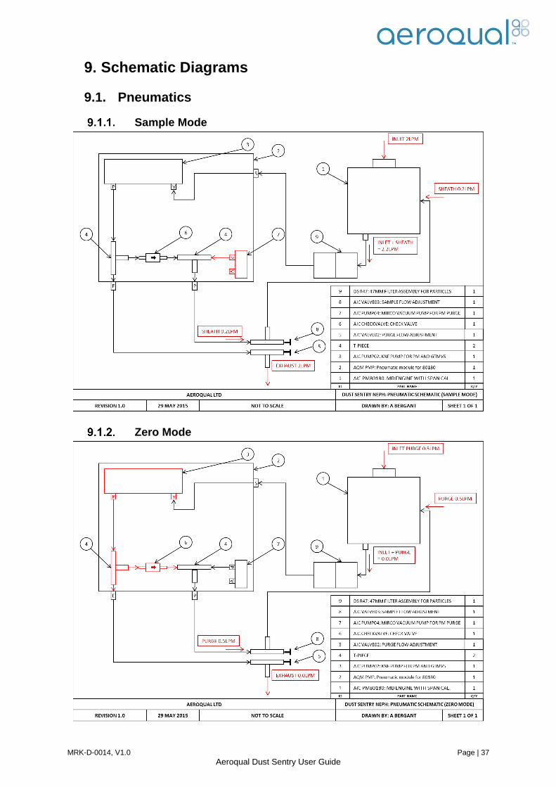
Schematic Diagrams
9.1. Pneumatics
Sample Mode
Zero Mode

MRK-D-0014, V1.0 Page | 38
Aeroqual Dust Sentry User Guide
9.2. Electrical
9.3. Communication

MRK-D-0014, V1.0 Page | 39
Aeroqual Dust Sentry User Guide
Third Party Sensors
10.1. Met One MSO Description: Measures wind speed and direction; air temperature; relative
humidity; and barometric pressure
Specifications: For full details visit the company website www.metone.com
10.1. Vaisala Weather Transmitter WXT520 Description: Measures wind speed and direction; liquid precipitation; barometric
pressure; air temperature; and relative humidity
Specifications: For full details visit the company website www.vaisala.com
Wind Speed
Range 0-50 m/s
Accuracy ±2%
Resolution 0.1 m/s
Wind Direction
Range 0-360°
Accuracy ±5°
Resolution 1°
Air Temperature
Range
Accuracy
-40°C - +60°C
±0.5°C
Resolution 0.1°C
Relative Humidity
Range
Accuracy
Resolution
0-100%
±4%
1%
Barometric Pressure
Range
Accuracy
Resolution
500-1100 mbars
± 2 mbars
0.1 mbar
Wind Speed
Range
Accuracy
0-60 m/s
±3% (0-35 m/s)
Wind Direction
Range
Accuracy
0-360°
±3°
Liquid Precipitation
Rainfall
Output Resolution
0.1mm/min
Barometric Pressure
Range
Accuracy
600-1100 hPa
±1 hPa @ -52 to +60 °C
Air Temperature
Range
Accuracy @ +20 °C
-52 to +60 °C
±0.3 °C
Relative Humidity
Measurement range
Accuracy
0-100 %RH
±3 %RH (0-90 %RH); ±5 %RH (90-100
%RH)

MRK-D-0014, V1.0 Page | 40
Aeroqual Dust Sentry User Guide
10.2. Gill WindSonic Description: 2-axis ultrasonic wind sensor, measures wind speed and
direction
Specifications: For full details visit the company website www.gill.co.uk
Wind Speed
Range 0-60 m/s
Accuracy ±2⁰ @ 12 m/s
Resolution 0.01 m/s
Wind Direction
Range 0-359° (no dead band)
Accuracy ±3⁰ @ 12 m/s
Resolution 1 °
10.3. Cirrus MK427 Noise Sensor
Description: Outdoor environmental noise meter:
Specifications: For full details visit the website www.cirrus-environmental.
com/
10.4. Novalynx 240-200SZ Silicon Pyranometer Description: Outdoor environmental solar radiation meter:
Specifications: For full details visit the website www.novalynx.com/
Frequency Weighting dB(A) to IEC 61672-1:2002
Automatic Calibration Electrostatic Actuator System
with DC voltage control
Measurement Range 30 – 100dB(A)
Resolution 0.1 dBA
Sensor High stability silicon voltaic detector
Accuracy ± 5% typical under natural daylight conditions
Sensitivity 100 µA per 1000 W/m² typical
Linearity Max deviation of 1% up to 3000 W/m²
Resolution 0.1 W/m2
Temperature
dependence 0.15% per °C max
Operating
temperature -40°C to +65°C (-40°F to +149°F)
MRK-D-0014, V1.0 Page | 41
Aeroqual Dust Sentry User Guide
Mounting and Site Positioning Guidelines It is important that the positioning of the Dust Sentry is suitable so as to yield data which is
representative of that specific location.
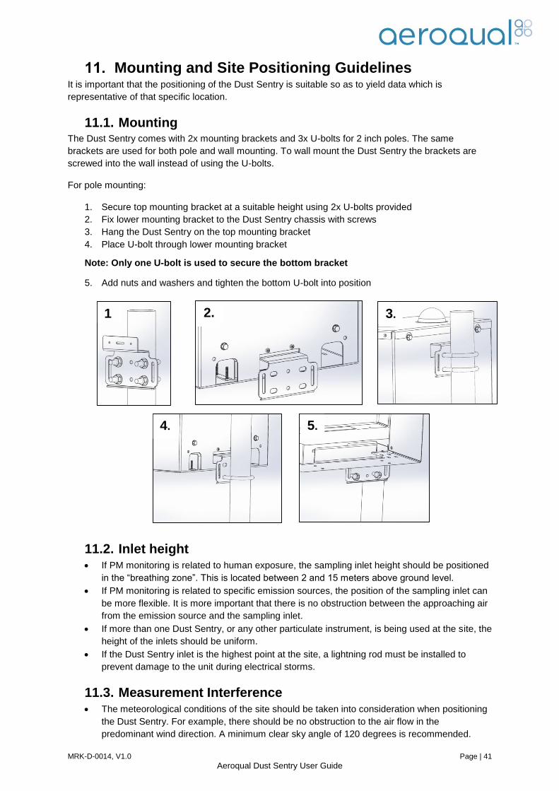
11.1. Mounting The Dust Sentry comes with 2x mounting brackets and 3x U-bolts for 2 inch poles. The same
brackets are used for both pole and wall mounting. To wall mount the Dust Sentry the brackets are
screwed into the wall instead of using the U-bolts.
For pole mounting:
1. Secure top mounting bracket at a suitable height using 2x U-bolts provided
2. Fix lower mounting bracket to the Dust Sentry chassis with screws
3. Hang the Dust Sentry on the top mounting bracket
4. Place U-bolt through lower mounting bracket
Note: Only one U-bolt is used to secure the bottom bracket
5. Add nuts and washers and tighten the bottom U-bolt into position
11.2. Inlet height If PM monitoring is related to human exposure, the sampling inlet height should be positioned
in the “breathing zone”. This is located between 2 and 15 meters above ground level.
If PM monitoring is related to specific emission sources, the position of the sampling inlet can
be more flexible. It is more important that there is no obstruction between the approaching air
from the emission source and the sampling inlet.
If more than one Dust Sentry, or any other particulate instrument, is being used at the site, the
height of the inlets should be uniform.
If the Dust Sentry inlet is the highest point at the site, a lightning rod must be installed to
prevent damage to the unit during electrical storms.
11.3. Measurement Interference The meteorological conditions of the site should be taken into consideration when positioning
the Dust Sentry. For example, there should be no obstruction to the air flow in the
predominant wind direction. A minimum clear sky angle of 120 degrees is recommended.
1
.
2. 3.
4. 5.

MRK-D-0014, V1.0 Page | 42
Aeroqual Dust Sentry User Guide
The inlet should be at least 1 meter away from any objects that could potentially influence the
airflow characteristics e.g. trees, vertical surfaces or walls.
Avoid overhead high-voltage cables which may cause electrical interference with the
sampling equipment.
Demolition/construction activities and change to normal transport patterns due to road works
etc. can significantly affect the data. Ensure a record of such events is kept to account for
unexpected peaks in concentration.
11.4. Safety The intended data capture rate should be considered when positioning the Dust Sentry. If
data capture above 90% is essential, the unit should be located in an area which has 24 hour
access available.
The positioning should allow for routine maintenance checks to be performed safely by
personnel.
If using a tripod, ensure the tripod legs are bolted to the ground to prevent the unit from
falling. Ensure the Dust Sentry is in a secure location to avoid vandalism or theft.

MRK-D-0014, V1.0 Page | 43
Aeroqual Dust Sentry User Guide
Appendix
12.1. Warranty
Please review the Aeroqual Warranty Policy on our website at www.aeroqual.com
12.2. Technical Support Technical information, service and spare parts are available through your distributor. In addition,
worldwide technical support is available from Aeroqual Ltd. Please contact Aeroqual Technical Support
by email: [email protected]. This will generate an automatic ticket and your enquiry will be
addressed as quickly as possible by a qualified service person.
Aeroqual Limited
109 Valley Road, Mt Eden, Auckland 1024, New Zealand
Phone: +64 9 623 3013
Fax: +64 9 623 3012
Email: [email protected]
12.3. Declarations Copyright Aeroqual Limited. All rights reserved. Reproduction, transfer, distribution or storage of part
or all of the contents of this document in any form without the prior written permission of Aeroqual
Limited is prohibited.
“Aeroqual” is a registered trademark of Aeroqual Limited. Other product and company names
mentioned herein may also be trademarks or trade names.
Aeroqual operates a policy of continuous development. Aeroqual reserves the right to make changes
and improvements to any of the products described in this document without prior notice.
Under no circumstances shall Aeroqual be responsible for any loss of data or income or any special,
incidental, consequential or indirect damages howsoever caused.
The contents of this document are provided "as is". Except as required by applicable law, no
warranties of any kind, either express or implied, including, but not limited to, the implied warranties of
merchantability and fitness for a particular purpose, are made in relation to the accuracy, reliability or
contents of this document.
Aeroqual reserves the right to revise this document or withdraw it at any time without prior notice. The availability of particular products may vary by region. Please check with the Aeroqual dealer nearest to you.
© Aeroqual Limited 2015. All rights reserved.
1. The Aeroqual Dust Sentry complies with EN 61000-6-1:2001 2. The Aeroqual Dust Sentry complies with EN 61000-6-3:2001 3. The Aeroqual Dust Sentry complies with Part 15 of the FCC Rules. Operation is subject to the
following two conditions: (1) these devices may not cause harmful interference, and (2) these devices must accept any interference received, including interference that may cause undesired operation.
4. The Aeroqual Dust Sentry has achieved MCERTs certification for indicative ambient particulate monitor

MRK-D-0014, V1.0 Page | 44
Aeroqual Dust Sentry User Guide
USE SENSIBLY Use the Aeroqual DUST SENTRY instrument only as per this user guide.
USE AEROQUAL APPROVED SERVICE
Only approved service personnel must work on this product.
ACCESSORIES
Use only approved accessories. Do not connect incompatible products.
CONNECTING TO OTHER DEVICES
When connecting to any other device, read the appropriate user guide for detailed safety
instructions. Do not connect incompatible products.