Embed Size (px)
Citation preview
MRI3-ITE(R) – Time overcurrent relay with thermal replica and earth current measuring
Manual MRI3-ITER (Revision A)

Woodward Manual MRI3-ITER GB
2 DOK-TD-MRI3 ITERE Rev.A
Woodward Governor Company reserves the right to update any portion of this publication at any time. Information provided by Woodward Governor Company is believed to be correct and reliable. However, no responsibility is as-
sumed by Woodward Governor Company unless otherwise expressly undertaken.
© Woodward 1994-2008

Manual MRI3-ITER GB Woodward
DOK-TD-MRI3 ITERE Rev.A 3
Contents
1. Introduction and Application ...................................................................... 5
2. Features and characteristics ...................................................................... 6
3. Design ........................................................................................................... 7 3.1 Connections ........................................................................................................................ 7
3.1.1 Analogue input circuits .................................................................................................... 8 3.1.2 Output relays ................................................................................................................... 9
3.2 Relay output contacts .......................................................................................................... 9 3.2.1 Blocking input ................................................................................................................ 10 3.2.2 External reset input ....................................................................................................... 10 3.2.3 Fault recorder ................................................................................................................ 10
3.3 Front plate ......................................................................................................................... 12
4. Working principle ....................................................................................... 14 4.1 Analog circuits ................................................................................................................... 14 4.2 Digital circuits .................................................................................................................... 14 4.3 Thermal replica .................................................................................................................. 15
4.3.1 Definitions ...................................................................................................................... 15 4.4 Algorithm ........................................................................................................................... 16 4.5 Earth fault protection ......................................................................................................... 19
4.5.1 Generator stator earth fault protection .......................................................................... 19 4.5.2 System earth fault protection ........................................................................................ 19
4.6 Earth-fault directional feature (ER-relay type) ................................................................... 20 4.7 Demand imposed on the main current transformers ......................................................... 22
5. Operation and settings .............................................................................. 23 5.1 Display ............................................................................................................................... 23
5.1.1 LEDs .............................................................................................................................. 25 5.2 Setting procedure .............................................................................................................. 27 5.3 System parameter ............................................................................................................. 27
5.3.1 Display of measuring values as primary quantities (Iprim phase) ................................... 27 5.3.2 Display of earth current as primary quantity (Iprim earth) ............................................... 27 5.3.3 Display of residual voltage UE as primary quantity (Uprim/Usec) ..................................... 27 5.3.4 Voltage transformer connection for residual voltage measuring (3pha/e-n/1:1) ........... 27 5.3.5 Nominal frequency ........................................................................................................ 28 5.3.6 Display of the activation storage (FLSH/NOFL) ............................................................ 28 5.3.7 Parameter switch/external triggering of the fault recorder ............................................ 28
5.4 Protection parameters ....................................................................................................... 29 5.4.1 Pickup value of the thermal overload protection IB,A and IB,T ........................................ 29 5.4.2 Constant k ..................................................................................................................... 29 5.4.3 Energizing delay (time) for the thermal overload .......................................................... 29 5.4.4 Time constant ............................................................................................................. 29 5.4.5 Pickup current for phase over current element (I>) ...................................................... 29 5.4.6 Time current characteristics for phase overcurrent element (CHAR I>) ....................... 30 5.4.7 Trip delay or time multiplier for phase over current element (tI>) ................................. 30 5.4.8 Reset setting for inverse time tripping characteristics in the phase current path ......... 30 5.4.9 Current setting for high set element (I>>) ..................................................................... 30 5.4.10 Trip delay for high set element (tI>>) ........................................................................ 30 5.4.11 Pickup value for residual voltage UE (ITER-relay type) ............................................. 31 5.4.12 Pickup current for earth fault element (IE>) ................................................................ 31 5.4.13 WARN/TRIP changeover .......................................................................................... 31 5.4.14 Time current characteristics for earth fault element (CHAR IE) (not ER device type) ... 31 5.4.15 Trip delay or time multiplier for earth fault element (tIE>) ........................................... 31 5.4.16 Resetting time for inverse time earth fault element (not ER-relay type) ................... 31 5.4.17 Current setting for high set element of earth fault supervision (IE>>) ........................ 31 5.4.18 Trip delay for high set element of earth fault supervision (tIE>>) ................................ 32 5.4.19 COS/SIN Measurement (ER - relay type) ................................................................. 32 5.4.20 Block/Trip – time (only ITE-device type) ................................................................... 32 5.4.21 Circuit breaker failure protection tCBFP ....................................................................... 32 5.4.22 Adjustment of the slave address ............................................................................... 32

Woodward Manual MRI3-ITER GB
4 DOK-TD-MRI3 ITERE Rev.A
5.4.23 Setting of Baud-rate (applies for Modbus Protocol only) .......................................... 32 5.4.24 Setting of parity (applies for Modbus Protocol only) ................................................. 32
5.5 Fault recorder ................................................................................................................... 33 5.5.1 Adjustment of the fault recorder ................................................................................... 33 5.5.2 Number of the fault recordings ..................................................................................... 33 5.5.3 Adjustment of trigger occurrences ................................................................................ 33 5.5.4 Pre-trigger time (Tpre) .................................................................................................... 33
5.6 Adjustment of the clock ..................................................................................................... 33 5.7 Additional functions ........................................................................................................... 34
5.7.1 Blocking of the protective functions .............................................................................. 34 5.8 Indication of measuring and fault values .......................................................................... 37
5.8.1 Indication of measuring values ..................................................................................... 37 5.8.2 Unit of the measuring values displayed ........................................................................ 37 5.8.3 Indication of fault data ................................................................................................... 38 5.8.4 Fault memory ................................................................................................................ 38
5.9 Reset ................................................................................................................................. 39 5.9.1 Erasure of fault storage ................................................................................................ 39 5.9.2 Reset of the thermal replica register ............................................................................. 39
6. Relay testing and commissioning ............................................................ 40 6.1 Power-On .......................................................................................................................... 40 6.2 Testing the output relays and LEDs ................................................................................. 40 6.3 Checking the set values .................................................................................................... 40 6.4 Secondary injection test .................................................................................................... 40
6.4.1 Test equipment ............................................................................................................. 40 6.4.2 Example of test circuit for MRI3-ITE ............................................................................. 41 6.4.3 Checking the input circuits and measured values ........................................................ 41 6.4.4 Example of a test circuit with earth fault directional feature ......................................... 42 6.4.5 Checking the operating and resetting values of the relay ............................................ 43 6.4.6 Checking the relay operating time ................................................................................ 43 6.4.7 Checking the high set element of the relay .................................................................. 43 6.4.8 Checking the external blocking and reset functions ..................................................... 43 6.4.9 Testing the external blocking with Block/Trip function .................................................. 44 6.4.10 Test of the CB failure protection ............................................................................... 44
6.5 Primary injection test ........................................................................................................ 44 6.6 Maintenance ..................................................................................................................... 45
7. Technical data ............................................................................................ 46 7.1 Measuring circuits ............................................................................................................. 46 7.2 Common data ................................................................................................................... 46 7.3 Setting ranges and steps .................................................................................................. 47
7.3.1 Systemparameter ......................................................................................................... 47 7.3.2 Overload protection ...................................................................................................... 48 7.3.3 Over current time protection ......................................................................................... 49 7.3.4 Earth fault protection ..................................................................................................... 50 7.3.5 Earth fault protection (ER-Type) ................................................................................... 50 7.3.6 Determination of earth fault direction (MRl3-ITER) ...................................................... 51 7.3.7 BlockTrip – time** ......................................................................................................... 51 7.3.8 Switch failure protection ................................................................................................ 51 7.3.9 Interface parameter ...................................................................................................... 51 7.3.10 Parameter for the fault recorder................................................................................ 51
7.4 Tripping characteristics ..................................................................................................... 52 7.4.1 Thermal characteristic .................................................................................................. 52 7.4.2 Preload factor ............................................................................................................... 53 7.4.3 Inverse time over current protection relay .................................................................... 54
7.5 Tripping characteristics ..................................................................................................... 55 7.6 Output relays .................................................................................................................... 58
8. Order form .................................................................................................. 59
Manual MRI3-ITER GB Woodward
DOK-TD-MRI3 ITERE Rev.A 5
1. Introduction and Application The digital multifunctional relay MRI3-ITE(R) has been designed as a universal time over current protection relay with thermal replica for generators, transformers and cables. The relay gives a complete thermal characteristic of the electrical equipment to be protected taking into account its initial load. The MRI3-ITE(R) furthermore provides a universal time over current and earth fault protection with the following functions: Integrated determination of earth fault direction for application to power system networks with isolated or arc suppressing coil (Peterson coil) neutral earthing (ER-relay type), independent (Definite) time over current relay. inverse time over current relay with selectable characteristics, two-element (low and high set) earth fault protection with definite or inverse time characteristics.
Woodward Manual MRI3-ITER GB
6 DOK-TD-MRI3 ITERE Rev.A
2. Features and characteristics Microprocessor technology with self-supervision, measuring of phase current as RMS value, digital filtering of the measured values by using discrete Fourier analysis to suppress the high frequence harmonics and DC components induced by faults or system operations (earth current only), in accordance with the requirements as per IEC 255-8, VDE 435 part 3011 for overload relays, two parameter sets, selectable protective functions between:
- definite time over current relay and - inverse time over current relay,
selectable inverse time characteristics according to IEC 255-4: - Normal Inverse (Type A) - Very Inverse (Type B) - Extremely Inverse (Type C) - Special characteristics,
Reset mode for inverse time characteristics selectable, high set over current element with instantaneous trip, two-element (inverse time and definite time) over current relay both for phase and earth faults, determination of earth short-circuit fault direction for systems with isolated or compensated neutral point, Display of measuring values as primary quantities, measuring of phase current of the short circuit breaker operation, blocking of high set element (e.g. for selective fault detection through minor over current protection units after unsuccessful AR), the protective functions can be freely assigned to the output relays (assignment matrix), withdrawable modules with automatic short circuiters of C.T. inputs when modules are with-drawn, storage of trip values and switching-off time (tCBFP) of 5 fault occurrences (fail-safe of voltage), recording of up to eight fault occurrences with time stamp, switch failure protection, serial data exchange via RS485 interface possible; alternatively with SEG RS485 Pro- Open Data Protocol or Modbus Protocol, Display of date and time.
Important: For additional common data of all MR-relays please refer to manual „MR-Digital Multifunctional re-lays“.
Manual MRI3-ITER GB Woodward
DOK-TD-MRI3 ITERE Rev.A 7
3. Design
3.1 Connections
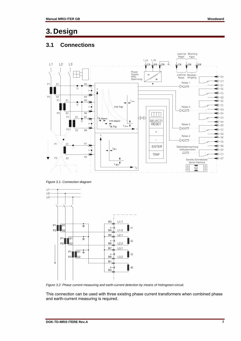
Figure 3.1: Connection diagram
Figure 3.2: Phase current measuring and earth-current detection by means of Holmgreen-circuit.
This connection can be used with three existing phase current transformers when combined phase and earth-current measuring is required.
Woodward Manual MRI3-ITER GB
8 DOK-TD-MRI3 ITERE Rev.A
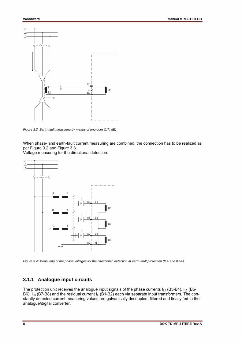
Figure 3.3: Earth-fault measuring by means of ring-core C.T. (IE)
When phase- and earth-fault current measuring are combined, the connection has to be realized as per Figure 3.2 and Figure 3.3. Voltage measuring for the directional detection:
Figure 3.4: Measuring of the phase voltages for the directional detection at earth-fault protection (IE> and IE>>).
3.1.1 Analogue input circuits The protection unit receives the analogue input signals of the phase currents IL1 (B3-B4), IL2 (B5-B6), IL3 (B7-B8) and the residual current IE (B1-B2) each via separate input transformers. The con-stantly detected current measuring values are galvanically decoupled, filtered and finally fed to the analogue/digital converter.
Manual MRI3-ITER GB Woodward
DOK-TD-MRI3 ITERE Rev.A 9
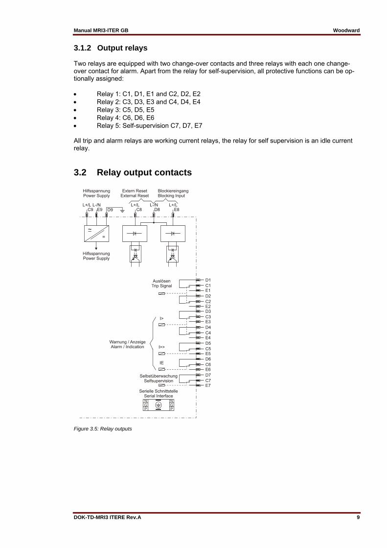
3.1.2 Output relays Two relays are equipped with two change-over contacts and three relays with each one change-over contact for alarm. Apart from the relay for self-supervision, all protective functions can be op-tionally assigned: Relay 1: C1, D1, E1 and C2, D2, E2 Relay 2: C3, D3, E3 and C4, D4, E4 Relay 3: C5, D5, E5 Relay 4: C6, D6, E6 Relay 5: Self-supervision C7, D7, E7 All trip and alarm relays are working current relays, the relay for self supervision is an idle current relay.
3.2 Relay output contacts
Figure 3.5: Relay outputs

Woodward Manual MRI3-ITER GB
10 DOK-TD-MRI3 ITERE Rev.A
3.2.1 Blocking input The function for blocking can be parameterized arbitrary. When an auxiliary voltage is connected to D8/E8 those relay functions will be blocked which were parameterized before (see chapter 5.7.1).
3.2.2 External reset input See chapter 5.9
3.2.3 Fault recorder The MRI3-ITER has a fault value recorder which records the measured analogue values as instantaneous values. The instantaneous values iL1, iL2, iL3, iE, are scanned at a raster of 1.25 ms (at 50 Hz) and 1.041 ms (at 60 Hz) and saved in a cyclic buffer. It is possible to store 1 - 8 fault occurrences with a total recording time of 16 s (with 50 Hz) and 13.33 s (with 60 Hz) per channel. Storage division Independent of the recording time, the entire storage capacity can be divided into several cases of disturbance with a shorter recording time each. In addition, the deletion behavior of the fault recorder can be influenced. No writing over If 2, 4 or 8 recordings are chosen, the complete memory is divided into the relevant number of partial segments. If this max. number of fault event has been exceeded, the fault recorder block any further recordings in order to prevent that the stored data are written over. After the data have been read and deleted, the recorder to ready again for further action. Writing over If 1, 3 or 7 recordings are chosen, the relevant number of partial segments is reserved in the com-plete memory. If the memory is full, a new recording will always write over the oldest one. The memory part of the fault recorder is designed as circulating storage. In this example 7 fault re-cords can be stored (written over). Memory space 6 to 4 is occupied. Memory space 5 is currently being written in
Figure 3.6: Division of the memory into 8 segments, for exam-ple
Since memory spaces 6, 7 and 8 are occupied, this example shows that the memory has been as-signed more than eight recordings. This means that No. 6 is the oldest fault recording and No. 4 the most recent one.

Manual MRI3-ITER GB Woodward
DOK-TD-MRI3 ITERE Rev.A 11
Figure 3.7: Basic set-up of the fault recorder
Each memory segment has a specified storage time which permits setting of a time prior to the trigger event. Via the interface RS485 the data can be read and processed by means of a PC with HTL/PL-Soft4. The data is graphically edited and displayed. Bi-nary tracks are recorded as well, e.g. activation and trip.
Woodward Manual MRI3-ITER GB
12 DOK-TD-MRI3 ITERE Rev.A
3.3 Front plate
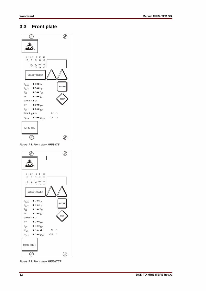
Figure 3.8: Front plate MRI3-ITE
Figure 3.9: Front plate MRI3-ITER

Manual MRI3-ITER GB Woodward
DOK-TD-MRI3 ITERE Rev.A 13
The LED RS, A and T yellow light up yellow (MRI3-ITE) The LED RS, IP and IQ light up yellow (MRI3-ITER). All other LEDs are two-colored. LEDs left to the alphanumerical display light-up green during mea-suring and red at alarm. LEDs underneath the pushbutton <SELECT/RESET> light-up green during setting and inquiry of the setting values printed left to the LEDs. They light-up red when the setting values printed at the right to the LEDs are activated. The LED labeled with the letters LR is a light while the fault recorder is being adjusted.
Woodward Manual MRI3-ITER GB
14 DOK-TD-MRI3 ITERE Rev.A
4. Working principle
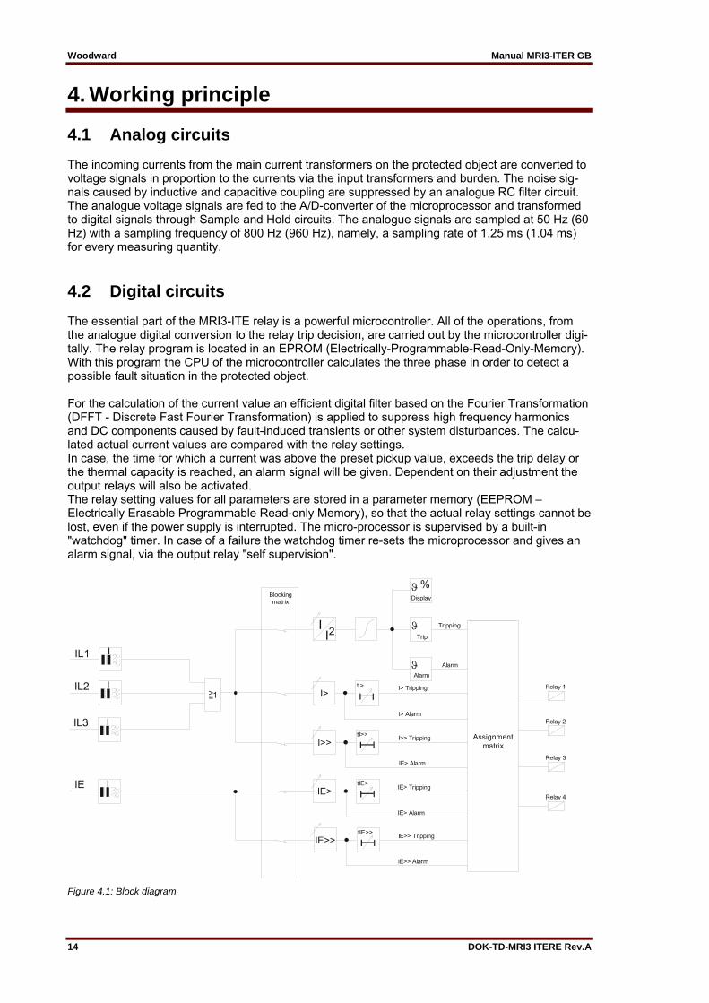
4.1 Analog circuits The incoming currents from the main current transformers on the protected object are converted to voltage signals in proportion to the currents via the input transformers and burden. The noise sig-nals caused by inductive and capacitive coupling are suppressed by an analogue RC filter circuit. The analogue voltage signals are fed to the A/D-converter of the microprocessor and transformed to digital signals through Sample and Hold circuits. The analogue signals are sampled at 50 Hz (60 Hz) with a sampling frequency of 800 Hz (960 Hz), namely, a sampling rate of 1.25 ms (1.04 ms) for every measuring quantity.
4.2 Digital circuits The essential part of the MRI3-ITE relay is a powerful microcontroller. All of the operations, from the analogue digital conversion to the relay trip decision, are carried out by the microcontroller digi-tally. The relay program is located in an EPROM (Electrically-Programmable-Read-Only-Memory). With this program the CPU of the microcontroller calculates the three phase in order to detect a possible fault situation in the protected object. For the calculation of the current value an efficient digital filter based on the Fourier Transformation (DFFT - Discrete Fast Fourier Transformation) is applied to suppress high frequency harmonics and DC components caused by fault-induced transients or other system disturbances. The calcu-lated actual current values are compared with the relay settings. In case, the time for which a current was above the preset pickup value, exceeds the trip delay or the thermal capacity is reached, an alarm signal will be given. Dependent on their adjustment the output relays will also be activated. The relay setting values for all parameters are stored in a parameter memory (EEPROM – Electrically Erasable Programmable Read-only Memory), so that the actual relay settings cannot be lost, even if the power supply is interrupted. The micro-processor is supervised by a built-in "watchdog" timer. In case of a failure the watchdog timer re-sets the microprocessor and gives an alarm signal, via the output relay "self supervision".
Figure 4.1: Block diagram
Manual MRI3-ITER GB Woodward
DOK-TD-MRI3 ITERE Rev.A 15
4.3 Thermal replica
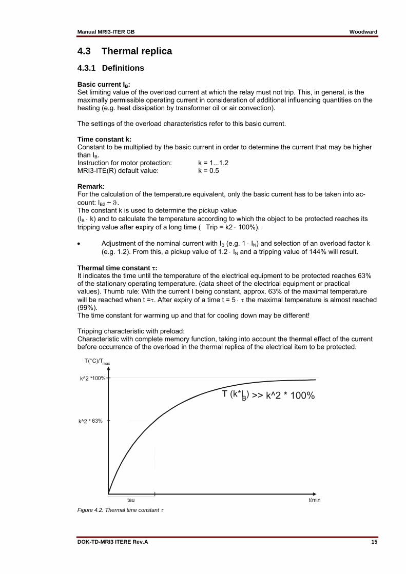
4.3.1 Definitions Basic current IB: Set limiting value of the overload current at which the relay must not trip. This, in general, is the maximally permissible operating current in consideration of additional influencing quantities on the heating (e.g. heat dissipation by transformer oil or air convection). The settings of the overload characteristics refer to this basic current. Time constant k: Constant to be multiplied by the basic current in order to determine the current that may be higher than IB. Instruction for motor protection: k = 1...1.2 MRI3-ITE(R) default value: k = 0.5 Remark: For the calculation of the temperature equivalent, only the basic current has to be taken into ac-count: IB2 ~ . The constant k is used to determine the pickup value (IB k) and to calculate the temperature according to which the object to be protected reaches its tripping value after expiry of a long time (�Trip = k2 100%). Adjustment of the nominal current with IB (e.g. 1 IN) and selection of an overload factor k (e.g. 1.2). From this, a pickup value of 1.2 IN and a tripping value of 144% will result. Thermal time constant : It indicates the time until the temperature of the electrical equipment to be protected reaches 63% of the stationary operating temperature. (data sheet of the electrical equipment or practical values). Thumb rule: With the current I being constant, approx. 63% of the maximal temperature will be reached when t =. After expiry of a time t = 5 the maximal temperature is almost reached (99%). The time constant for warming up and that for cooling down may be different! Tripping characteristic with preload: Characteristic with complete memory function, taking into account the thermal effect of the current before occurrence of the overload in the thermal replica of the electrical item to be protected.
Figure 4.2: Thermal time constant

Woodward Manual MRI3-ITER GB
16 DOK-TD-MRI3 ITERE Rev.A
4.4 Algorithm Based on the defined thermal model, one can de-duce that an energy Q is stored in the electrical equipment. After expiry of a long time and with a constant cur-rent load, a stationary condition will be achieved in which the temperature of the electrical equipment does not increase anymore. The heat supplied for a unit of time is equal to that released by cooling down (steady energy balance). Qreleased = Qsupplied The supplied thermal energy as well as the temperature of the electrical equipment in stationary condition are in proportion to the square of the phase current (e.g. ohmic losses and iron losses in the transformer). Q I² or I² Since the pickup value in the MRI3-ITE is deter-mined by IB , the following relation is effective: n k² (IB k)² For this purpose, the temperature T that really prevails in the electrical equipment needs to be known. This temperature (in%) is described in the thermal replica through the temperature equiv-alent k IB. When being loaded with the maximum permissible operating current B in stationary condition, the electrical equipment reaches the maximum allowed operating temperature B. For this load, the temperature equivalent is defined as k2 100%.
%I
KlB· 100%
I.e.: At a load with I = 0.9 x (k IB) and k IB = 1.2, and according to the before indicated definition, the temperature reaches 81% of the maximum permissible operating temperature. For an electrical equipment that - after initial load - will be loaded beyond the admissible operating current (I > k•IB), the following temperature curve will result:
Figure 4.3: Warming up of an electrical item
Manual MRI3-ITER GB Woodward
DOK-TD-MRI3 ITERE Rev.A 17
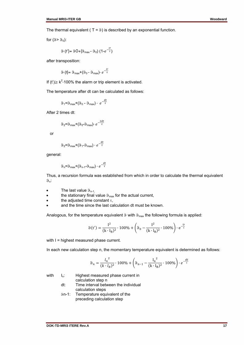
The thermal equivalent ( T = ) is described by an exponential function. for (> 0):
(t‘)= 0+(max - 0) (1- ) after transposition:
(t)= max+(0 - max)·
If (t’) k2·100% the alarm or trip element is activated. The temperature after dt can be calculated as follows:
1=max+(0 - max) ·
After 2 times dt:
2=max+(0-max)·
or
2=max+(1-max) ·
general:
n=max+(n-1-max) ·
Thus, a recursion formula was established from which in order to calculate the thermal equivalent n: The last value n-1, the stationary final value max for the actual current, the adjusted time constant , and the time since the last calculation dt must be known. Analogous, for the temperature equivalent with max the following formula is applied:
tI
k · IB· 100%
Ik · lB
· 100% · e
with I = highest measured phase current. In each new calculation step n, the momentary temperature equivalent is determined as follows:
·
· 100% I
k · IB· 100% ·
with In: Highest measured phase current in calculation step n dt: Time interval between the individual calculation steps n-1: Temperature equivalent of the preceding calculation step
Woodward Manual MRI3-ITER GB
18 DOK-TD-MRI3 ITERE Rev.A
The temperature equivalent n-1 has not been calculated after start of the protection program (con-nection of auxiliary voltage), therefore, the temperature state of the electrical item to be protected is expected to be cold. If, however, the electrical equipment has been initially loaded, it will take approximately 3 x warming up, (at constant load) until the thermal equivalent equals the real state.
Different time constants: After switching off the electrical equipment (In = 0) temperature will decrease and tend towards �n = 0 (environmental temperature). e.g.: cooling down = 2 warming up Depending on the comparison between the last measured current and the actual current the cooling down or warming up constant will be applied for calculation. In In-1 warming up In < In-1 cooling down If the relay is supplied by the mains to be protected, i.e. if the relay is not supplied to auxiliary vol-tage after tripping of the mains c.b., the following has to be considered: After return of the supply voltage, it is assumed that the electric item is in cold condition. In this case this assumption does not comply with the reality. Therefore an external supply voltage should be applied. The tripping criterion for the alarm or tripping element of the thermal characteristic is: Trip > k2 · 100% The effective values of the measured phase currents are detected by calculating the root out of the integral of a period’s momentary current squares. Calculation of the thermal equivalent is always based on the highest of the three phase currents.

Manual MRI3-ITER GB Woodward
DOK-TD-MRI3 ITERE Rev.A 19
4.5 Earth fault protection
4.5.1 Generator stator earth fault protection With the generator neutral point earthed as shown in Figure 4.4 the MRI3-ITER picks up only to phase earth faults between the generator and the location of the current transformers supplying the relay. Earth faults beyond the current transformers, i.e. on the consumer or line side, will not be detected.
Figure 4.4: Generator stator earth fault protection
4.5.2 System earth fault protection With the generator neutral point earthed as shown in Figure 4.5, the MRI3-ITER picks up only to earth faults in the power system connected to the generator. It does not pick up to earth faults on the generator terminals or in generator stator.
Figure 4.5: System earth fault protection
Woodward Manual MRI3-ITER GB
20 DOK-TD-MRI3 ITERE Rev.A
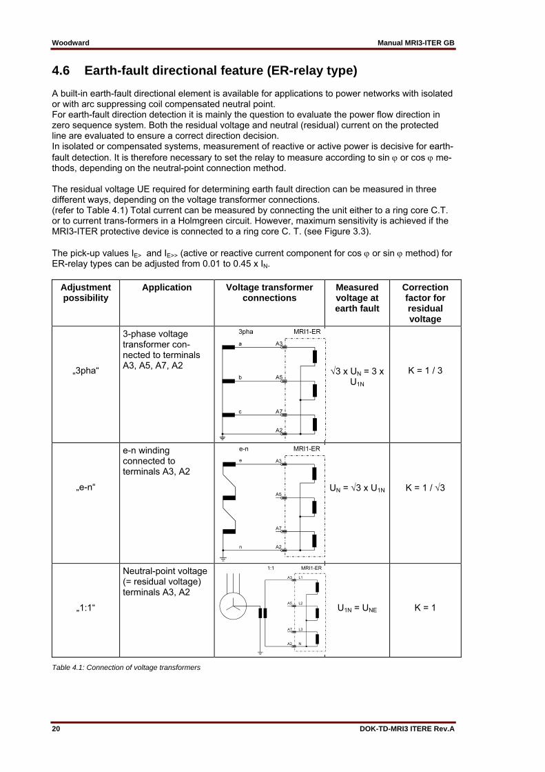
4.6 Earth-fault directional feature (ER-relay type) A built-in earth-fault directional element is available for applications to power networks with isolated or with arc suppressing coil compensated neutral point. For earth-fault direction detection it is mainly the question to evaluate the power flow direction in zero sequence system. Both the residual voltage and neutral (residual) current on the protected line are evaluated to ensure a correct direction decision. In isolated or compensated systems, measurement of reactive or active power is decisive for earth-fault detection. It is therefore necessary to set the relay to measure according to sin or cos me-thods, depending on the neutral-point connection method. The residual voltage UE required for determining earth fault direction can be measured in three different ways, depending on the voltage transformer connections. (refer to Table 4.1) Total current can be measured by connecting the unit either to a ring core C.T. or to current trans-formers in a Holmgreen circuit. However, maximum sensitivity is achieved if the MRI3-ITER protective device is connected to a ring core C. T. (see Figure 3.3). The pick-up values IE> and IE>> (active or reactive current component for cos or sin method) for ER-relay types can be adjusted from 0.01 to 0.45 x IN.
Adjustment possibility
Application Voltage transformer connections
Measured voltage at earth fault
Correction factor for residual voltage
„3pha“
3-phase voltage transformer con-nected to terminals A3, A5, A7, A2
3 x UN = 3 x U1N
K = 1 / 3
„e-n“
e-n winding connected to terminals A3, A2
UN = 3 x U1N K = 1 / 3
„1:1“
Neutral-point voltage (= residual voltage) terminals A3, A2 U1N = UNE K = 1
Table 4.1: Connection of voltage transformers

Manual MRI3-ITER GB Woodward
DOK-TD-MRI3 ITERE Rev.A 21
Figure 4.6: Phase position between the residual voltage and zero sequence current for faulted and non-faulted lines in case of isolated systems (sin )
UE - residual voltage IE - zero sequence current IC - capacitive component of zero sequence current IW - resistive component of zero sequence current By calculating the reactive current component (sin adjustment) and then comparing the phase angle in relation to the residual voltage UE, the ER/XR-relay type determines whether the line to be protected is earth-faulted. On non-earth-faulted lines, the capacitive component Ic(a) of the total current precedes the residual voltage by an angle of 90°. In case of a faulty line the capacity current IC(b) lags behind the residual voltage at 90°.
Figure 4.7: Phase position between the residual voltage and zero sequence current for faulted and non-faulted lines in case of compensated systems (cos)
UE - residual voltage IE - zero sequence current IL - inductive component of zero sequence cur-rent (caused by Petersen coil) IC - capacitive component of zero sequence current IW - resistive component of zero sequence current
Woodward Manual MRI3-ITER GB
22 DOK-TD-MRI3 ITERE Rev.A
In compensated mains the earthfault direction cannot be determined from the reactive current components because the reactive part of the earth current depends upon the compensation level of the mains. The ohmic component of the total cur-rent (calculated by cos adjustment) is used in order to determine the direction. The resistive component in the non-faulted line is in phase with the residual voltage, while the re-sistive component in the faulted line is opposite in phase with the residual voltage. By means of an efficient digital filter harmonics and fault transients in the fault current are sup-pressed. Thus, the uneven harmonics which, for instance, are caused an electric arc fault, do not impair the protective function.
4.7 Demand imposed on the main current transformers The current transformers have to be rated in such a way, that a saturation should not occur within the following operating current ranges: Independent time over current function: K1 = 2 Inverse time over current function: K1 = 20 High-set function: K1 = 1.2 - 1.5 K1 = Current factor related to set value Moreover, the current transformers have to be rated according to the maximum expected short cir-cuit current in the network or in the protected objects. The low power consumption in the current circuit of MRI3-ITER, namely <0,2 VA, has a positive ef-fect on the selection of current transformers. It implies that, if an electromechanical relay is re-placed by MRI3-ITER, a high accuracy limit factor is automatically obtained by using the same cur-rent transformer.

Manual MRI3-ITER GB Woodward
DOK-TD-MRI3 ITERE Rev.A 23
5. Operation and settings
5.1 Display
Function Display shows Pressed pushbutton Corresponding LED
Normal operation SEG Measured operating values actual measured val-
ues, related to IN, Temperature equivalent in %
<SELECT/RESET> one time for each value
L1, L2, L3, E A, T, IP, IQ
Measuring range overflow max. <SELECT/RESET> A und T Display of the second rated repetition current
SEC 0.002-50.0 kA=prim
<+> <-><SELECT/RESET> L1, L2, L3, E
Rated frequency f = 50 / f = 60 <+> <-><SELECT/RESET> LED-blinking after activation FLSH/NOFL <+> <-><SELECT/RESET> Parameter switch/external trigger-ing of the fault recorder
SET1, SET2, B_S2, R_S2, B_FR, R_FR, S2_FR
<+> <-><SELECT/RESET> P2
Constant k Factor for pickup cur-rent
<+> <-><SELECT/RESET> kA and kT
Time constant Cooling time/warming up time constant
<+> <-><SELECT/RESET> C and W
Blocking of function EXIT <+> until max. setting value
LED of blocked parameter
Characteristics DEFT,NINV, VINV, EINV, LINV, RINV,
<+> <-><SELECT/RESET>
CHAR I>
Characteristics DEFT, NINV, VINV, EINV, LINV, RINV
<+> <-><SELECT/RESET> CHAR IE>
Switch failure protection CBFP after tripping C. B. Recorded fault data Phase currents, earth
currents and tempera-ture equivalent
<SELECT/RESET> one time for each phase
L1, L2, L3, E A and T
Enquiry failure memory FLT1, FLT2..... <+> <-><SELECT/RESET> L1, L2, L3, E I>, I>>, IE>, IE>>,
Delete failure memory wait <+> <-><SELECT/RESET> Relay trip TRIP <TRIP> or after fault trip-
ping
Secret password input „XXXX“ <+><-> <ENTER> <SELECT/RESET>
System reset SEG <SELECT/RESET> for about 3 s
Manual trip TRI? <TRIP> three times Inquire password PSW? <TRIP><ENTER> Blocking of protection function BLOC, NO_B <ENTER> und <TRIP> Change over the blockage function ²)
PR_B, TR_B <ENTER> und <TRIP>; <+><->
I>, I>>, IE>, IE>>, oder tI>, tI>>, tIE>, tIE>>
Relay assignment e. g. _ 2 _ _ <ENTER> and <TRIP> Trigger signal for the fault recorder P_UP; A_PI; TRIP;
TEST <+> <-><SELECT/RESET> FR
Number of fault occurences S = 2, S = 4, S = 8 <+> <-><SELECT/RESET> FR Display of date and time Y = 99, M = 10, D = 1,
h = 12, m = 2, s = 12 <+> <-><SELECT/RESET> �
Slave address of serial interface 1-32 <+> <-><SELECT/RESET> RS Baud-Rate 1) 1200-9600 <SELECT/RESET> <+><-> RS Parity-Check 1) even odd no <SELECT/RESET> <+><-> RS Parameter switch SET1; SET2 <+> <-><SELECT/RESET> P2 Setting values: Currents and time delays
Current and time settings
<SELECT/RESET> one time for each parameter
IB,A; IB,T; kA; kT; I>; CHAR I>; tI>; I>>; tI>>; IE>; CHAR IE>; tIE>; IE>>;

Woodward Manual MRI3-ITER GB
24 DOK-TD-MRI3 ITERE Rev.A
Function Display shows Pressed pushbutton Corresponding LED
tIE>> Save parameter? SAV? <ENTER> Save parameter! SAV! <ENTER> for about 3 s Display of software-version First part (e.g. D21-)
Second part (e.g. 1.00)<TRIP> one time for each part
Setting of the transformer connec-tions of UE>
1:1; e-n; 3pha <+> <-><SELECT/RESET> UE>
Table 5.1: Possible indication messages on the display
1) only Modbus 2) only ITE
Manual MRI3-ITER GB Woodward
DOK-TD-MRI3 ITERE Rev.A 25
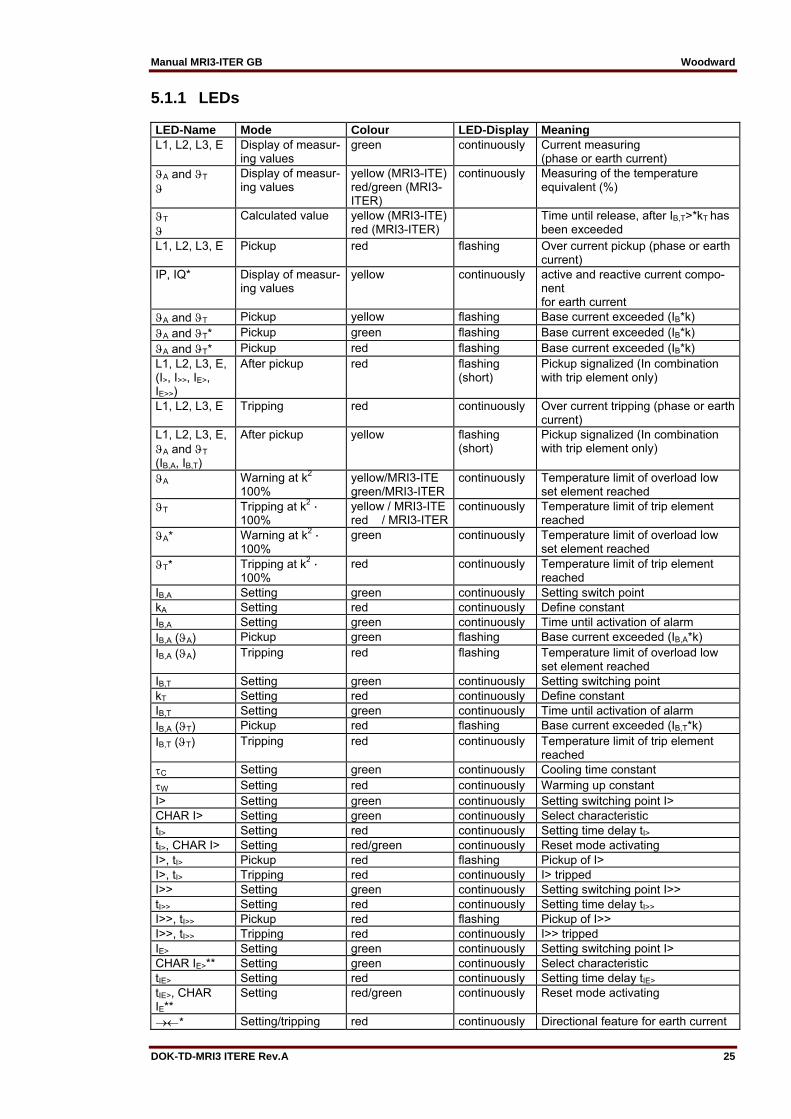
5.1.1 LEDs LED-Name Mode Colour LED-Display Meaning L1, L2, L3, E Display of measur-
ing values green continuously Current measuring
(phase or earth current) A and T
Display of measur-ing values
yellow (MRI3-ITE) red/green (MRI3-ITER)
continuously Measuring of the temperature equivalent (%)
T
Calculated value yellow (MRI3-ITE)
red (MRI3-ITER) Time until release, after IB,T>*kT has
been exceeded L1, L2, L3, E Pickup red flashing Over current pickup (phase or earth
current) IP, IQ* Display of measur-
ing values yellow continuously active and reactive current compo-
nent for earth current
A and T Pickup yellow flashing Base current exceeded (IB*k) A and T* Pickup green flashing Base current exceeded (IB*k) A and T* Pickup red flashing Base current exceeded (IB*k) L1, L2, L3, E, (I>, I>>, IE>, IE>>)
After pickup red flashing (short)
Pickup signalized (In combination with trip element only)
L1, L2, L3, E Tripping red continuously Over current tripping (phase or earth current)
L1, L2, L3, E, A and T (IB,A, IB,T)
After pickup yellow flashing (short)
Pickup signalized (In combination with trip element only)
A Warning at k2 � 100%
yellow/MRI3-ITE green/MRI3-ITER
continuously Temperature limit of overload low set element reached
T Tripping at k2 · 100%
yellow / MRI3-ITEred / MRI3-ITER
continuously Temperature limit of trip element reached
A* Warning at k2 · 100%
green continuously Temperature limit of overload low set element reached
T* Tripping at k2 · 100%
red continuously Temperature limit of trip element reached
IB,A Setting green continuously Setting switch point kA Setting red continuously Define constant IB,A Setting green continuously Time until activation of alarm IB,A (A) Pickup green flashing Base current exceeded (IB,A*k) IB,A (A) Tripping red flashing Temperature limit of overload low
set element reached IB,T Setting green continuously Setting switching point kT Setting red continuously Define constant IB,T Setting green continuously Time until activation of alarm IB,A (T) Pickup red flashing Base current exceeded (IB,T*k) IB,T (T) Tripping red continuously Temperature limit of trip element
reached C Setting green continuously Cooling time constant W Setting red continuously Warming up constant I> Setting green continuously Setting switching point I> CHAR I> Setting green continuously Select characteristic tI> Setting red continuously Setting time delay tI> tI>, CHAR I> Setting red/green continuously Reset mode activating I>, tI> Pickup red flashing Pickup of I> I>, tI> Tripping red continuously I> tripped I>> Setting green continuously Setting switching point I>> tI>> Setting red continuously Setting time delay tI>> I>>, tI>> Pickup red flashing Pickup of I>> I>>, tI>> Tripping red continuously I>> tripped IE> Setting green continuously Setting switching point I> CHAR IE>** Setting green continuously Select characteristic tIE> Setting red continuously Setting time delay tIE> tIE>, CHAR IE**
Setting red/green continuously Reset mode activating
* Setting/tripping red continuously Directional feature for earth current

Woodward Manual MRI3-ITER GB
26 DOK-TD-MRI3 ITERE Rev.A
LED-Name Mode Colour LED-Display MeaningIE>, tIE> Pickup red flashing Pickup of IE> IE>, tIE> Tripping red continuously IE> tripped IE>> Setting green continuously Setting switching point IE>> tIE>> Setting red continuously Setting time delay tIE>> IE>>, tIE>> Pickup red flashing Pickup of IE>> IE>>, tIE>> Tripping red continuously IE>>, tripped RS Setting yellow continuously Setting slave address
Table 5.2: LED-indication
* MRI3-ITER type only **only MRI3-ITE type
Manual MRI3-ITER GB Woodward
DOK-TD-MRI3 ITERE Rev.A 27
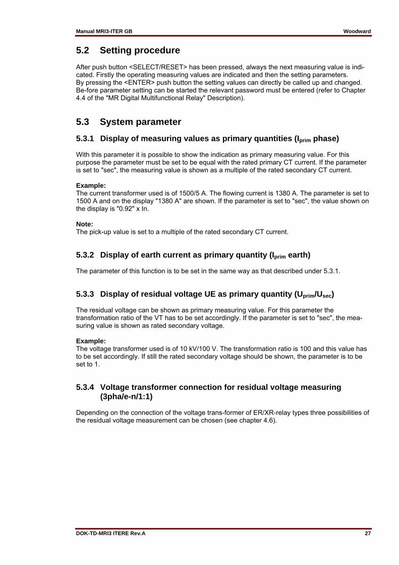
5.2 Setting procedure After push button <SELECT/RESET> has been pressed, always the next measuring value is indi-cated. Firstly the operating measuring values are indicated and then the setting parameters. By pressing the <ENTER> push button the setting values can directly be called up and changed. Be-fore parameter setting can be started the relevant password must be entered (refer to Chapter 4.4 of the "MR Digital Multifunctional Relay" Description).
5.3 System parameter
5.3.1 Display of measuring values as primary quantities (Iprim phase) With this parameter it is possible to show the indication as primary measuring value. For this purpose the parameter must be set to be equal with the rated primary CT current. If the parameter is set to "sec", the measuring value is shown as a multiple of the rated secondary CT current. Example: The current transformer used is of 1500/5 A. The flowing current is 1380 A. The parameter is set to 1500 A and on the display "1380 A" are shown. If the parameter is set to "sec", the value shown on the display is "0.92" x In. Note: The pick-up value is set to a multiple of the rated secondary CT current.
5.3.2 Display of earth current as primary quantity (Iprim earth) The parameter of this function is to be set in the same way as that described under 5.3.1.
5.3.3 Display of residual voltage UE as primary quantity (Uprim/Usec) The residual voltage can be shown as primary measuring value. For this parameter the transformation ratio of the VT has to be set accordingly. If the parameter is set to "sec", the mea-suring value is shown as rated secondary voltage. Example: The voltage transformer used is of 10 kV/100 V. The transformation ratio is 100 and this value has to be set accordingly. If still the rated secondary voltage should be shown, the parameter is to be set to 1.
5.3.4 Voltage transformer connection for residual voltage measuring (3pha/e-n/1:1)
Depending on the connection of the voltage trans-former of ER/XR-relay types three possibilities of the residual voltage measurement can be chosen (see chapter 4.6).
Woodward Manual MRI3-ITER GB
28 DOK-TD-MRI3 ITERE Rev.A
5.3.5 Nominal frequency The adapted FFT-algorithm requires the nominal frequency as a parameter for correct digital sampling and filtering of the input currents. By pressing <SELECT> the display shows "f=50" or "f=60". The desired nominal frequency can be adjusted by <+> or <-> and then stored with <ENTER>.
5.3.6 Display of the activation storage (FLSH/NOFL) If after an activation the existing current drops again below the pickup value, e.g. I>, without a trip has been initiated, LED I> signals that an activation has occurred by flashing fast. The LED keeps flashing until it is reset again (push button <RESET>). Flashing can be suppressed when the pa-rameter is set to NOFL.
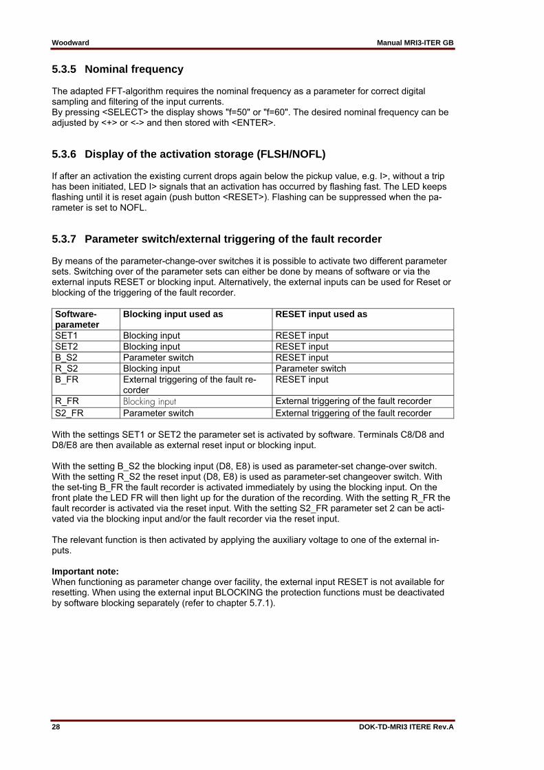
5.3.7 Parameter switch/external triggering of the fault recorder By means of the parameter-change-over switches it is possible to activate two different parameter sets. Switching over of the parameter sets can either be done by means of software or via the external inputs RESET or blocking input. Alternatively, the external inputs can be used for Reset or blocking of the triggering of the fault recorder. Software-parameter
Blocking input used as RESET input used as
SET1 Blocking input RESET input SET2 Blocking input RESET input B_S2 Parameter switch RESET input R_S2 Blocking input Parameter switch B_FR External triggering of the fault re-
corder RESET input
R_FR Blocking input External triggering of the fault recorder S2_FR Parameter switch External triggering of the fault recorder
With the settings SET1 or SET2 the parameter set is activated by software. Terminals C8/D8 and D8/E8 are then available as external reset input or blocking input. With the setting B_S2 the blocking input (D8, E8) is used as parameter-set change-over switch. With the setting R_S2 the reset input (D8, E8) is used as parameter-set changeover switch. With the set-ting B_FR the fault recorder is activated immediately by using the blocking input. On the front plate the LED FR will then light up for the duration of the recording. With the setting R_FR the fault recorder is activated via the reset input. With the setting S2_FR parameter set 2 can be acti-vated via the blocking input and/or the fault recorder via the reset input. The relevant function is then activated by applying the auxiliary voltage to one of the external in-puts. Important note: When functioning as parameter change over facility, the external input RESET is not available for resetting. When using the external input BLOCKING the protection functions must be deactivated by software blocking separately (refer to chapter 5.7.1).
Manual MRI3-ITER GB Woodward
DOK-TD-MRI3 ITERE Rev.A 29
5.4 Protection parameters
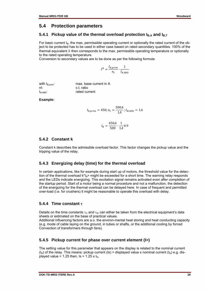
5.4.1 Pickup value of the thermal overload protection IB,A and IB,T For basic current IB, the max. permissible operating current or optionally the rated current of the ob-ject to be protected has to be used in either case based on rated secondary quantities. 100% of the thermal equivalent then corresponds to the max. permissible operating temperature or optionally to the rated operating temperature. Conversion to secondary values are to be done as per the following formula:
, ·1
,
with IB,prim: max. base current in A nI: c.t. ratio IN.MRI: rated current Example:
, 450;500
1; , 1
450500
·1
10.9
5.4.2 Constant k Constant k describes the admissible overload factor. This factor changes the pickup value and the tripping value of the relay.
5.4.3 Energizing delay (time) for the thermal overload In certain applications, like for example during start up of motors, the threshold value for the detec-tion of the thermal overload k*IB> might be exceeded for a short time. The warning relay responds and the LEDs indicate energizing. This excitation signal remains activated even after completion of the startup period. Start of a motor being a normal procedure and not a malfunction, the detection of the energizing for the thermal overload can be delayed here. In case of frequent and permitted over-load (i.e. for crushers) it might be reasonable to operate this overload with delay.
5.4.4 Time constant Details on the time constants C and W can either be taken from the electrical equipment’s data sheets or estimated on the base of practical values. Additional influencing factors are a.o. the environ-mental heat storing and heat conducting capacity (e.g. mode of cable laying on the ground, in tubes or shafts, or the additional cooling by forced Convection of transformers through fans).
5.4.5 Pickup current for phase over current element (I>) The setting value for this parameter that appears on the display is related to the nominal current (IN) of the relay. This means: pickup current (Is) = displayed value x nominal current (IN) e.g. dis-played value = 1.25 then, Is = 1.25 x IN.
Woodward Manual MRI3-ITER GB
30 DOK-TD-MRI3 ITERE Rev.A
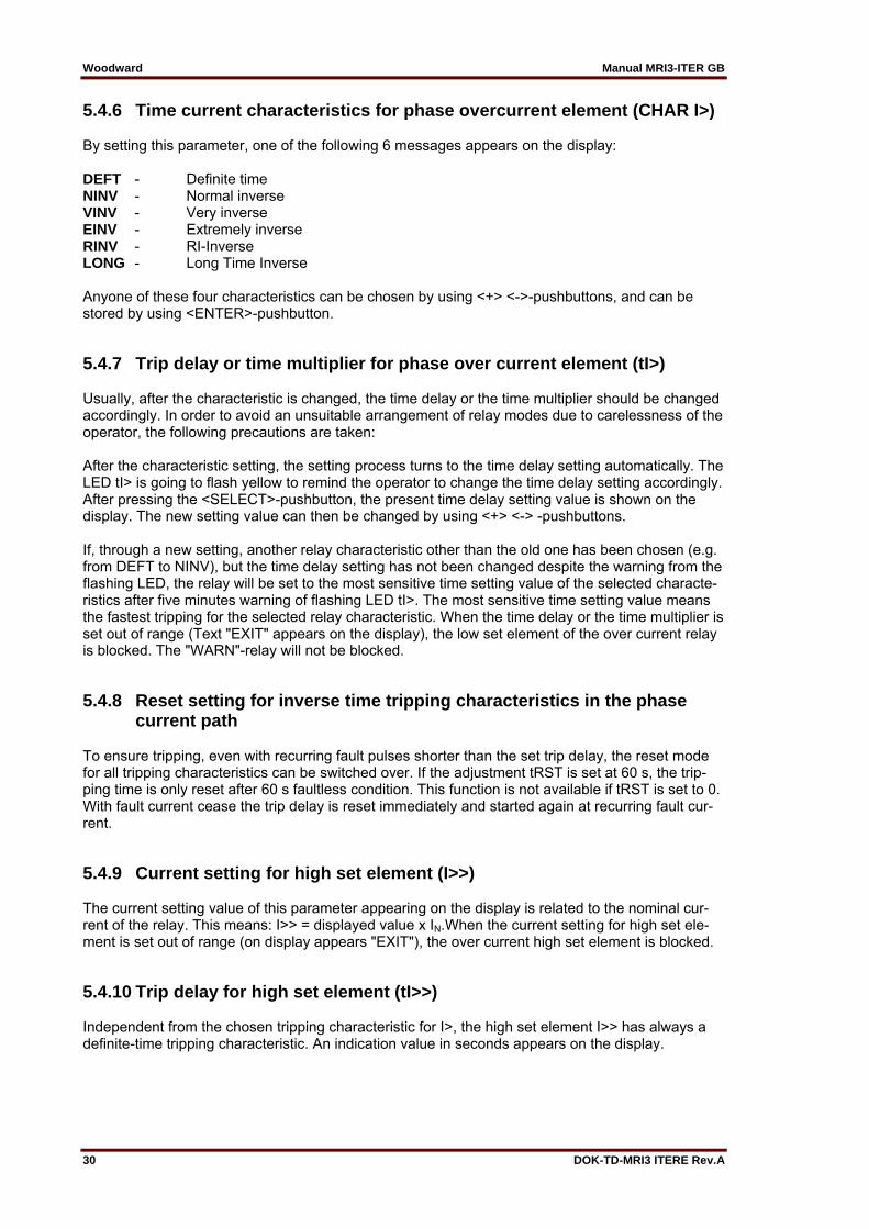
5.4.6 Time current characteristics for phase overcurrent element (CHAR I>) By setting this parameter, one of the following 6 messages appears on the display: DEFT - Definite time NINV - Normal inverse VINV - Very inverse EINV - Extremely inverse RINV - RI-Inverse LONG - Long Time Inverse Anyone of these four characteristics can be chosen by using <+> <->-pushbuttons, and can be stored by using <ENTER>-pushbutton.
5.4.7 Trip delay or time multiplier for phase over current element (tI>) Usually, after the characteristic is changed, the time delay or the time multiplier should be changed accordingly. In order to avoid an unsuitable arrangement of relay modes due to carelessness of the operator, the following precautions are taken: After the characteristic setting, the setting process turns to the time delay setting automatically. The LED tI> is going to flash yellow to remind the operator to change the time delay setting accordingly. After pressing the <SELECT>-pushbutton, the present time delay setting value is shown on the display. The new setting value can then be changed by using <+> <-> -pushbuttons. If, through a new setting, another relay characteristic other than the old one has been chosen (e.g. from DEFT to NINV), but the time delay setting has not been changed despite the warning from the flashing LED, the relay will be set to the most sensitive time setting value of the selected characte-ristics after five minutes warning of flashing LED tI>. The most sensitive time setting value means the fastest tripping for the selected relay characteristic. When the time delay or the time multiplier is set out of range (Text "EXIT" appears on the display), the low set element of the over current relay is blocked. The "WARN"-relay will not be blocked.
5.4.8 Reset setting for inverse time tripping characteristics in the phase current path
To ensure tripping, even with recurring fault pulses shorter than the set trip delay, the reset mode for all tripping characteristics can be switched over. If the adjustment tRST is set at 60 s, the trip-ping time is only reset after 60 s faultless condition. This function is not available if tRST is set to 0. With fault current cease the trip delay is reset immediately and started again at recurring fault cur-rent.
5.4.9 Current setting for high set element (I>>) The current setting value of this parameter appearing on the display is related to the nominal cur-rent of the relay. This means: I>> = displayed value x IN.When the current setting for high set ele-ment is set out of range (on display appears "EXIT"), the over current high set element is blocked.
5.4.10 Trip delay for high set element (tI>>) Independent from the chosen tripping characteristic for I>, the high set element I>> has always a definite-time tripping characteristic. An indication value in seconds appears on the display.

Manual MRI3-ITER GB Woodward
DOK-TD-MRI3 ITERE Rev.A 31
5.4.11 Pickup value for residual voltage UE (ITER-relay type) Regardless of the preset earth current, an earth fault is only identified if the residual voltage ex-ceeds the set reference value. This value is indicated in volt.
5.4.12 Pickup current for earth fault element (IE>) (Similar to 5.4.5)
5.4.13 WARN/TRIP changeover An earth fault can be parameterized as follows:
a) "warn" only the alarm relay trips
b) "TRIP" the trip relay trips and tripping values are stored.
5.4.14 Time current characteristics for earth fault element (CHAR IE) (not ER device type)
By setting this parameter, one of the following 7 messages appears on the display: DEFT - Definite Time (independent over current time protection) NINV - Normal inverse (Type A) VINV - Very inverse (Type B) EINV - Extremely inverse (Type C) RINV RI-Inverse LINV Long Time Inverse RXID Special characteristic Anyone of these four characteristics can be chosen by using <+> <->-pushbuttons, and can be stored by using <ENTER>-pushbutton.
5.4.15 Trip delay or time multiplier for earth fault element (tIE>) (Similar to 5.4.7)
5.4.16 Resetting time for inverse time earth fault element (not ER-relay type) (Similar to 5.4.8)
5.4.17 Current setting for high set element of earth fault supervision (IE>>) (Similar to 5.4.9)

Woodward Manual MRI3-ITER GB
32 DOK-TD-MRI3 ITERE Rev.A
5.4.18 Trip delay for high set element of earth fault supervision (tIE>>) (Similar to 5.4.10)
5.4.19 COS/SIN Measurement (ER - relay type) Depending on the neutral earthing connection of the protected system the directional element of the earth fault relay must be preset to cos or sin measurement. By pressing <SELECT/RESET> the display shows "COS" resp. "SIN". The desired measuring prin-ciple can be selected by <+> or <-> and must be entered with password.
5.4.20 Block/Trip – time (only ITE-device type) The block/trip time serves for detection of a c.b. failure protection by rear interlocking. It is activated by setting the blocking input D8/E8 and by setting the parameter to TR_B. After the set block/trip time has expired, the relay can be tripped if the excitation of a protective function has been applied the delay time of which has expired and the blocking function is still active. If the parameter PR_B is set, the individual protection stages are blocked (refer to Chapter 5.7.1).
5.4.21 Circuit breaker failure protection tCBFP The CB failure protection is based on supervision of phase currents during tripping events. Only af-ter tripping this protective function becomes active. The test criterion is whether all phase currents are dropped to <1% x IN within tCBFP (Circuit Breaker Failure Protection - adjustable between 0.1 - 2.0 s). If not all of the phase currents have dropped to <1%xIN within this time, CB failure is de-tected and the related relay activated. The CB failure protection function is deactivated again as soon as the phase currents have dropped to <1% x IN within tCBFP
5.4.22 Adjustment of the slave address Pressing pushbuttons <+> and <-> the slave ad-dress can be set in range of 1-32.
5.4.23 Setting of Baud-rate (applies for Modbus Protocol only) Different transmission rates (Baud rate) can be set for data transmission via Modbus Protocol. The rate can be changed by push buttons <+> and <-> and saved by pressing <ENTER>.
5.4.24 Setting of parity (applies for Modbus Protocol only) The following three parity settings are possible : "even" = even "odd" = odd "no" = no parity check The setting can be changed by push buttons <+> and <-> and saved by pressing <ENTER>.

Manual MRI3-ITER GB Woodward
DOK-TD-MRI3 ITERE Rev.A 33
5.5 Fault recorder
5.5.1 Adjustment of the fault recorder The MRI3-ITE is equipped with a fault recorder (see chapter 3.2.3). Three parameters can be de-termined.
5.5.2 Number of the fault recordings The max. recording time is 16 s at 50 Hz or 13.33 s at 60 Hz. The number of max. recordings requested has to be determined in advance. There is a choice of (1)* 2, (3)* 4 or (7)* 8 recordings and dependent on this the duration of the individual fault record-ings is defined, i.e. (1)* 2 recordings for a duration of 8 s (with 50 Hz) (6.66 s with 60 Hz) (3)* 4 recordings for a duration of 4 s (with 50 Hz) (3.33 s with 60 Hz) (7)* 8 recordings for a duration of 2 s (with 50 Hz) (1.66 s with 60 Hz) * is written over when a new trigger signal arrives
5.5.3 Adjustment of trigger occurrences There is a choice between four different occurrences: P_UP (Pickup) Storage is initiated after recognition of a general activation TRIP Storage is initiated after a trip has occurred A_PI (After Pickup) Storage is initiated after the last activation threshold was fallen short of. TEST Storing is activated by simultaneous actuation of the keys <+> and <->. During the recording time the display shows “Test”.
5.5.4 Pre-trigger time (Tpre) By the time Tpre it is determined which period of time prior to the trigger occurrence should be stored as well. It is possible to adjust a time between 0.05 s and 8 s. With keys <+> and <-> the values can be changed and with <ENTER> be saved.
5.6 Adjustment of the clock When adjusting the date and time, LED lights up. The adjustment method is as follows: Date: Year Y=00 Month M=00 Day D=00 Time: Hour h=00 Minute m=00 Second s=00 The clock starts with the set date and time as soon as the supply voltage is switched on. The time is safeguarded against short-term voltage failures (min. 6 minutes). Note: The window for parameter setting is located behind the measured value display. The parameter window can be accessed via the <SELECT/RESET> key.
Woodward Manual MRI3-ITER GB
34 DOK-TD-MRI3 ITERE Rev.A
5.7 Additional functions
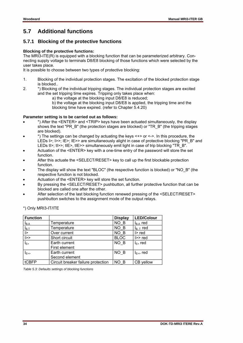
5.7.1 Blocking of the protective functions Blocking of the protective functions: The MRI3-ITE(R) is equipped with a blocking function that can be parameterized arbitrary. Con-necting supply voltage to terminals D8/E8 blocking of those functions which were selected by the user takes place. It is possible to choose between two types of protective blocking: 1. Blocking of the individual protection stages. The excitation of the blocked protection stage is blocked.. 2. *) Blocking of the individual tripping stages. The individual protection stages are excited and the set tripping time expires. Tripping only takes place when: a) the voltage at the blocking input D8/E8 is reduced; b) the voltage at the blocking input D8/E8 is applied, the tripping time and the blocking time have expired. (refer to Chapter 5.4.20) Parameter setting is to be carried out as follows: *) After the <ENTER> and <TRIP> keys have been actuated simultaneously, the display shows the text "PR_B" (the protection stages are blocked) or "TR_B" (the tripping stages are blocked). *) The settings can be changed by actuating the keys <+> or <->. In this procedure, the LEDs I>; I>>; IE>; IE>> are simultaneously alight in case of protective blocking "PR_B" and LEDs tI>; tI>>; tIE>, tIE>> simultaneously emit light in case of trip blocking "TR_B". Actuation of the <ENTER> key with a one-time entry of the password will store the set function. After this actuate the <SELECT/RESET> key to call up the first blockable protection function. The display will show the text "BLOC" (the respective function is blocked) or "NO_B" (the respective function is not blocked. Actuation of the <ENTER> key will store the set function. By pressing the <SELECT/RESET> pushbutton, all further protective function that can be blocked are called one after the other. After selection of the last blocking function renewed pressing of the <SELECT/RESET> pushbutton switches to the assignment mode of the output relays. *) Only MRI3-IT/ITE Function Display LED/Colour IB,A Temperature NO_B IB,A red IB,T Temperature NO_B IB, T red I> Over current NO_B I> red I>> Short circuit BLOC I>> red IE> Earth current
First element NO_B IE> red
IE>> Earth current Second element
NO_B IE>> red
tCBFP Circuit breaker failure protection NO_B CB yellow
Table 5.3: Defaults settings of blocking functions
Manual MRI3-ITER GB Woodward
DOK-TD-MRI3 ITERE Rev.A 35
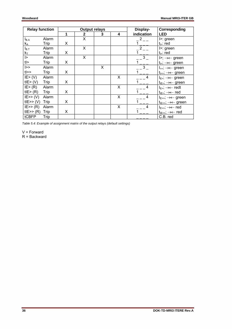
Assignment to the output relays: Unit MRI3-ITE has five output relays. The fifth out-put relay is provided as permanent alarm relay for self supervision is normally on. Output relays 1 - 4 are normally off and can be assigned as alarm or tripping relays to the frequency functions which can either be done by using the pushbut-tons on the front plate or via serial interface RS485. The assignment of the output relays is similar to the setting of parameters, however, only in the assignment mode. The assignment mode follows the blocking mode. The relays are assigned as follows: LEDs IB,A, IB,T, I>, I>>, IE> and IE>> are two-colored and light up green when the output relays are as-signed as alarm relays and red as tripping relays. Definition: Alarm relays are activated at pickup of the relay. Tripping relays are only activated after elapse of the tripping delay. After the relay assignment mode has been activated the LED I> lights up green. Now one or several of the four output relays can be assigned to element I> as alarm relays. At the same time the selected alarm relays for element I> are indicated on the display. Indication "1_ _ _" means that out-put relay 1 is assigned to this current element. When the display shows "_ _ _ _", no alarm re-lay is assigned to this current element. The assignment of output relays 1 - 4 can be changed by pressing <+> and <-> pushbuttons. The selected assignment can be stored by pressing pushbutton <ENTER> and subsequent input of the password. By pressing pushbutton <SELECT/RESET>, LED I> lights up red. The out-put relays can now be assigned to this current element as tripping relays. Relays 1-4 for the other elements are selected in the same way as described before. The assign-ment mode can be terminated at any time by pressing the <SELECT> pushbutton for some time (abt. 3 s). Note: The function of jumper J2 described in general description "MR Digital Multifunctional Re lays" has no function. For relays without assignment mode this jumper is used for parameter setting of alarm relays (activation at pickup or tripping).
A form is attached to this description where the setting requested by the customer can be filled-in.
Woodward Manual MRI3-ITER GB
36 DOK-TD-MRI3 ITERE Rev.A
Relay function Output relays Display- Corresponding 1 2 3 4 indication LED IB,A Alarm X _ 2 _ _ I>: green kA Trip X 1 _ _ _ tI>: red IB,T Alarm X _ 2 _ _ I>: green kT Trip X 1 _ _ _ tI>: red I> Alarm X _ _ 3 _ I>; green tI> Trip X 1 _ _ _ tI>; green I>> Alarm X _ _ 3 _ I>>; green tI>> Trip X 1 _ _ _ tI>>; green IE> (V) Alarm X _ _ _ 4 IE>; green tIE> (V) Trip X 1 _ _ _ tIE>; green IE> (R) Alarm X _ _ _ 4 IE>; redt tIE> (R) Trip X 1 _ _ _ tIE>; red IE>> (V) Alarm X _ _ _ 4 IE>>; green tIE>> (V) Trip X 1 _ _ _ tIE>>; green IE>> (R) Alarm X _ _ _ 4 IE>>; red tIE>> (R) Trip X 1 _ _ _ tIE>>; red tCBFP Trip _ _ _ _ C.B. red
Table 5.4: Example of assignment matrix of the output relays (default settings)
V = Forward R = Backward

Manual MRI3-ITER GB Woodward
DOK-TD-MRI3 ITERE Rev.A 37
5.8 Indication of measuring and fault values
5.8.1 Indication of measuring values The following measuring quantities can be indicated on the display during normal service: Apparent Current in phase 1 (LED L1 green) Apparent Current in phase 2 (LED L2 green) Apparent Current in phase 3 (LED L3 green) Temperature equivalent A> in % (LED A yellow), (for MRI3-ITE) Temperature equivalent T> in % (LED T red), (for MRI3-ITE) Temperature equivalent A> in % (LED > green), (for MRI3-ITER) Temperature equivalent T> in % (LED > red), (for MRI3-ITER) Time until release T in s (LED T red), (for MRI3-ITE) Time until release T in s (LED > red), (for MRI3-ITER) Apparent earth current (LED E green) Active earth current (LED E and IP green) * Reactive earth current (LED E and IQ green) * Residual voltage UE (LED UE) only at ITER-relay type Angle between IE and UE (only at ITER relay type)
5.8.2 Unit of the measuring values displayed The measuring values can optionally be shown in the display as a multiple of the "sec" rated value (xln) or as primary current (A). According to this the units of the display change as follows: Phase current Indication as Range Unit Secondary current Active portion IP
Reactive portion IQ
0.00 – 40.0 ±.00 – 40 ±.00 – 40.
x In x In x In
Primary current .000 – 999. k000 – k999 1k00 – 9k99 10k0 – 99k0 100k – 999k 1M00 – 2M00
A kA* kA kA kA MA
Earth current Indication as Range Unit Secondary current Active portion IP
Reactive portion IQ (E/SR/ER types)
.000 – 15.0 ±.00 – 40 ±.00 – 40.
x In x In x In
Secondary current Active portion IP
Reactive portion IQ
(X/XR types)
0.00 - 150 ±.00 – 150 ±.00 – 150
% IN % IN % IN
Primary earth current
.000 – 999. k000 – k999 1k00 – 9k99 10k0 – 99k0 100k – 999k 1M00 – 2M00
A kA* kA kA kA MA

Woodward Manual MRI3-ITER GB
38 DOK-TD-MRI3 ITERE Rev.A
Earth voltage Indication as Range Unit Sec. voltage 000V – 999V V Primary voltage .000 – 999
1K00 – 9K99 10K0 – 99K0 100K – 999K 1M00 – 9M99
kV kV kV kV MV
5.8.3 Indication of fault data All faults detected by the relay are indicated on the front plate optically. For this purpose, the four LEDs (L1, L2, L3, E) and the four function LEDs (I>, I>>, IE>, IE>> and ) are equipped at MRI3-ITER. If, for example an over current occurs, first the each phases will light up. LED I> lights up at the same time. After tripping the LEDs are lit permanently.
5.8.4 Fault memory When the relay is energized or trips, all fault data and times are stored in a non-volatile memory manner. The MRI3 is provided with a fault value recorder for max. eight fault occurrences. In the event of additional trippings always the oldest data set is written over. For fault indication not only the trip values are re-corded but also the status of LEDs. Fault values are indicated when push buttons <-> or <+> are pressed during normal measuring value indication. Normal measuring values are selected by pressing the <SELECT/RESET> button. When then the <-> button is pressed, the latest fault data set is shown. By repeated pressing the <-> button the last but one fault data set is shown etc. For indication of fault data sets abbreviations FLT1, FLT2, FLT3, ... are displayed (FLT1 means the latest fault data set recorded). At the same time the parameter set active at the occurrence is shown. By pressing <SELECT/RESET> the fault measuring values can be scrolled. By pressing <+> it can be scrolled back to a more recent fault data set. At first FLT8, FLT7, ... are always displayed. When fault recording is indicated (FLT1 etc), the LEDs flash in compliance with the stored trip information, i.e. those LEDs which showed a continuous light when the fault occurred are now blinking to indicate that it is not a current fault. LEDs which were blinking during trip conditions, (element had picked up) just briefly flash. If the relay is still in trip condition and not yet reset (TRIP is still displayed), no measuring values can be shown. To delete the trip store, the push button combination <SELECT/RESET> and <-> has to be pressed for about 3s. The display shows “wait”.
Manual MRI3-ITER GB Woodward
DOK-TD-MRI3 ITERE Rev.A 39
5.9 Reset Unit MRI3-ITER has the following three possibilities to reset the display of the unit as well as the output relay at jumper position J3=ON. Manual Reset Pressing the pushbutton <SELECT/RESET> for some time (about 3 s) Electrical Reset Through applying auxiliary voltage to C8/D8 Software Reset The software reset has the same effect as the <SELECT/RESET> pushbutton (see also communication protocol of RS485 interface). The display can only be reset when the pickup is not present anymore (otherwise "TRIP" remains in display). During resetting of the display the parameters are not affected.
5.9.1 Erasure of fault storage The fault storage is erased by pressing the key combination <SELECT/RESET> and <-> for about 3 s. At the display "Wait" appears.
5.9.2 Reset of the thermal replica register It is possible to reset the thermal replica to 0%. The thermal replica is reset by long pressing of the pushbuttons <SELECT/RESET> and <-> (for approx. 3 seconds).

Woodward Manual MRI3-ITER GB
40 DOK-TD-MRI3 ITERE Rev.A
6. Relay testing and commissioning The test instructions following below help to verify the protection relay performance before or dur-ing commissioning of the protection system. To avoid a relay damage and to ensure a correct relay operation, be sure that: The auxiliary power supply rating corresponds to the auxiliary voltage on site. The rated current of the relay corresponds to the plant data on site. The current transformers are connected to the relay correctly. All signal circuits and output relay circuits are connected correctly.
6.1 Power-On Note! Prior to switch on the auxiliary power supply, be sure that the auxiliary supply voltage corresponds with the rated data on the type plate. Switch on the auxiliary power supply to the relay and check that the message "SEG" appears on the display and the self supervision alarm relay (watchdog) is energized (Contact terminals D7 and E7 closed).
6.2 Testing the output relays and LEDs NOTE! Prior to commencing this test, interrupt the trip circuit to the circuit breaker if tripping is not desired. By pressing the pushbutton <TRIP> once, the display shows the first part of the software version of the relay (e.g. „D21-“). By pressing the pushbutton <TRIP> twice, the display shows the second part of the software version of the relay (e.g. „1.00“). The software version should be quoted in all correspondence. Pressing the <TRIP> button once more, the display shows "PSW?". Please enter the correct password to proceed with the test. The message "TRI?" will follow. Confirm this mes-sage by pressing the pushbutton <TRIP> again. All out-put relays and LEDs should then be acti-vated and the self supervision alarm relay (watchdog) be de-activated one after another with a time interval of 3 seconds. Thereafter, reset all output relays back to their normal positions by pressing the pushbutton <SELECT/RESET> (about 3 s).
6.3 Checking the set values By repeatedly pressing the pushbutton <SELECT>, all relay set values may be checked. Set value modification can be done with the pushbutton <+><-> and <ENTER>. For detailed in-formation about that, please refer to chapter 5. For a correct relay operation, be sure that the frequency set value (f=50/60) has been selected ac-cording to your system frequency (50 or 60 Hz).
6.4 Secondary injection test
6.4.1 Test equipment Ammeter with class 1 or better, auxiliary power supply with the voltage corresponding to the rated data on the type plate, single-phase current supply unit (adjustable from 0 to ≥ 4 x IN), timer to measure the operating time (Accuracy class ≤ ±10 ms), switching device and test leads and tools
Manual MRI3-ITER GB Woodward
DOK-TD-MRI3 ITERE Rev.A 41
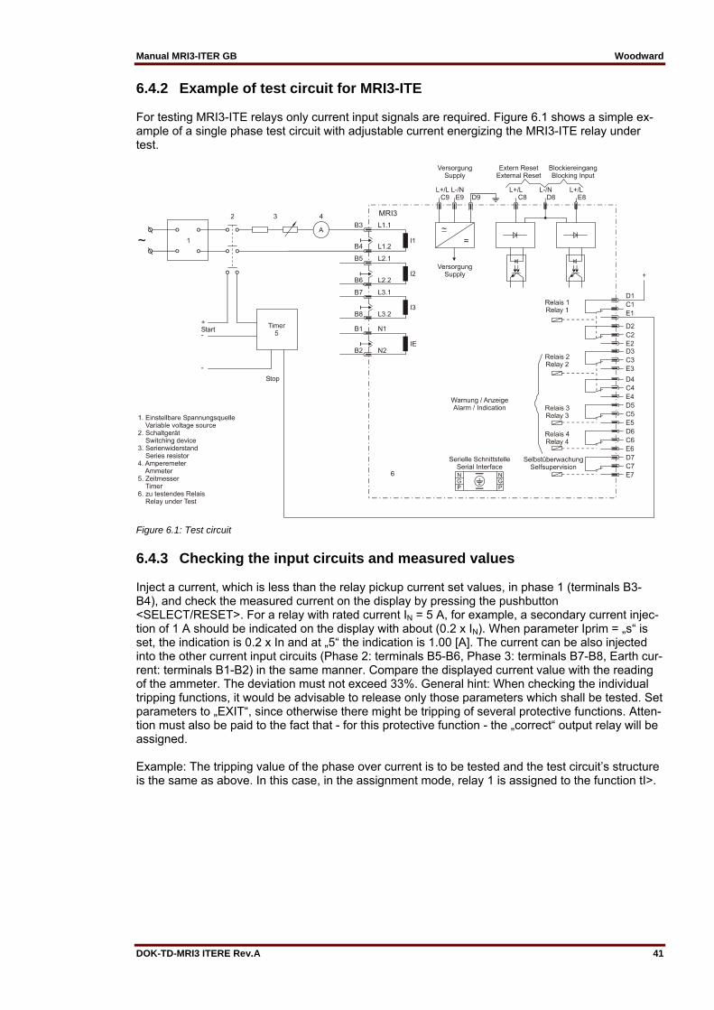
6.4.2 Example of test circuit for MRI3-ITE For testing MRI3-ITE relays only current input signals are required. Figure 6.1 shows a simple ex-ample of a single phase test circuit with adjustable current energizing the MRI3-ITE relay under test.
Figure 6.1: Test circuit
6.4.3 Checking the input circuits and measured values Inject a current, which is less than the relay pickup current set values, in phase 1 (terminals B3-B4), and check the measured current on the display by pressing the pushbutton <SELECT/RESET>. For a relay with rated current IN = 5 A, for example, a secondary current injec-tion of 1 A should be indicated on the display with about (0.2 x IN). When parameter Iprim = „s“ is set, the indication is 0.2 x In and at „5“ the indication is 1.00 [A]. The current can be also injected into the other current input circuits (Phase 2: terminals B5-B6, Phase 3: terminals B7-B8, Earth cur-rent: terminals B1-B2) in the same manner. Compare the displayed current value with the reading of the ammeter. The deviation must not exceed 33%. General hint: When checking the individual tripping functions, it would be advisable to release only those parameters which shall be tested. Set parameters to „EXIT“, since otherwise there might be tripping of several protective functions. Atten-tion must also be paid to the fact that - for this protective function - the „correct“ output relay will be assigned. Example: The tripping value of the phase over current is to be tested and the test circuit’s structure is the same as above. In this case, in the assignment mode, relay 1 is assigned to the function tI>.

Woodward Manual MRI3-ITER GB
42 DOK-TD-MRI3 ITERE Rev.A
6.4.4 Example of a test circuit with earth fault directional feature
Figure 6.2: Test circuit
For testing MRI3-ITER relays with earth fault directional feature, current and voltage sources are required, with one of the two sources having to be equipped with a phase shifter. Fig. 6.2 shows an example of a test circuit with variable current and voltage sources. First, the parameters IE> and IE>> must be set to "EXIT" in order to prevent possible tripping. For the pur-pose of testing the directional feature, a test voltage equal to the rated voltage is applied to termin-als A2/A5. The parameter "Voltage transformer connection for residual voltage measuring" (refer to 5.3.4) must be adjusted to "3Pha". The appropriate measuring value is selected via the <SELECT/RESET> key. The display must in-dicate 1/3 of the rated voltage (±0.5% Un). Now a current of 0.4 x IN is injected (terminals B1/B2). The display must now indicate a value of 0.40 (±3%). Finally, using the phase shifter, it must be checked whether the setting of the testing equipment coincides with the indication on the display (±3°). By using an RMS-metering instrument, a greater deviation may be observed if the test current contains harmonics. Because the MRI3-ITER relay measures only the fundamental component of the input signals, the harmonics will be rejected by the internal DFFT-digital filter. Whereas the RMS-metering instrument measures the RMS-value of the input signals.
Manual MRI3-ITER GB Woodward
DOK-TD-MRI3 ITERE Rev.A 43
6.4.5 Checking the operating and resetting values of the relay Inject a current which is less than the relay set values in phase 1 of the relay and gradually in-crease the current until the relay starts, i.e. at the moment when the LED I> and L1 light up or the alarm out-put relay I> is activated. Read the operating cur-rent indicated by the ammeter. The dev-iation must not exceed 5% of the set operating value. Furthermore, gradually decrease the current until the relay resets, i.e. the alarm output relay I> is disengaged. Check that the resetting current is not smaller than 0.97 times the operating current. Repeat the test on phase 2, phase 3 and earth cur-rent input circuits in the same manner.
6.4.6 Checking the relay operating time To check the relay operating time, a timer must be connected to the trip output relay contact. The timer should be started simultaneously with the current injection in the current input circuit and stopped by the trip relay contact. Set the current to a value corresponding to twice the operating value and inject the current instantaneously. The operating time measured by the timer should have a deviation of less than 3% of the set value or <20 ms. Repeat the test on the other phases or with the in-verse time characteristics in the similar manner. In case of inverse time characteristics the injected current should be selected according to the cha-racteristic curve, e.g. two times IS. The tripping time may be red from the characteristic curve dia-gram or calculated with the equations given under "technical data". Please observe that during the secondary injection test the test current must be very stable. Oth-erwise the test results may be wrong. This especially applies for currents smaller than 2 x IS , where the trip delays are in the steep range of the inverse curves.
6.4.7 Checking the high set element of the relay Set a current above the set operating value of I>>. Inject the current instantaneously and check that the alarm output relay I>> operates. Check the tripping time of the high set element according chapter 6.4.6 Check the accuracy of the operating current setting by gradually increasing the injected current un-til the I>> element picks up. Read the current value form the ammeter and compare with the de-sired setting. Repeat the entire test on other phases and earth current input circuits in the same manner. Note ! Where test currents >4 x IN are used, the thermal withstand capability of the current paths has to be considered (see technical data, chapter 7.1
6.4.8 Checking the external blocking and reset functions By means of the external blocking input, it is possible to block all protective functions. To give an example, the blocking function of the phase current high set element is described. This can be tested by first setting the parameter for the phase current high set element to „BLOC“ and then connecting the auxiliary voltage to terminals E8/D8. The phase current low set element I> should be set to EXIT for this test. Inject a test current which could cause a high set (I>>) tripping. Observe that there is no trip of any assigned output relay of the high set or low set element. Remove the auxiliary supply voltage from the blocking input. Inject a test current to trip the relay (message „TRIP“ on the display). Interrupt the test current and apply auxiliary supply voltage to the external reset input of the relay (terminals C8/D8). The display and LED indications should be reset immediately.
Woodward Manual MRI3-ITER GB
44 DOK-TD-MRI3 ITERE Rev.A
6.4.9 Testing the external blocking with Block/Trip function In order to simplify things, the short-circuit stage is to be tested here as described in Chapter 6.4.7. For this purpose, the parameter for the Block/Trip function must be set to "TR_B" (first value in the blocking menu of the protection functions Chapter 5.7.1). The appertaining Block/Trip time should be longer than the set tripping time tI>>. (Refer to Chapter 5.4.18). Here, too, a current is im-pressed which should make the short-circuit stage trip. After the Block/Trip time has expired, trip-ping will take place. Tripping takes place when: the blocking input has been set a tripping stage has been excited the appertaining tripping time has expired the Block/trip time has expired If the Block/Trip time is set shorter than the tripping time, tripping will only take place after the trip-ping time has expired.
6.4.10 Test of the CB failure protection For testing the tripping time a test current of about 2 times the rated current to be injected. The ti-mer is started upon tripping of the relay of a protection function (I>, I>>, IE>, IE>>) and stopped as soon as the relay for the CB failure protection has picked up. Message "CBFP" is displayed. The tripping time ascertained by the timer should not deviate more than 1% or, at short trip delay, less than 10 ms from the set tripping time. Alternatively, the timer can be started when the aux. voltage and the test current are injected simultaneously. The timer stops when the corresponding output relay for circuit breaker failure pro-tection trips. In this case the previously measured tripping delay has to be subtracted from the total tripping time measured.
6.5 Primary injection test Generally, a primary injection test could be carried out in the similar manner as the secondary in-jection test described above. With the difference that the protected power system should be, in this case, connected to the installed relays under test „on line“, and the test currents and voltages should be injected to the relay through the current and voltage transformers with the primary side energized. Since the cost and potential hazards are very high for such a test, primary injection tests are usually limited to very important protective relays in the power system. Because of its powerful combined indicating and measuring functions, the MRI3-ITER relay may be tested in the manner of a primary injection test without extra expenditure and time consumption. In actual service, for example, the measured current values on the MRI3-ITER relay display may be compared phase by phase with the current indications of the ammeter of the switchboard to ve-rify that the relay works and measures correctly.
Manual MRI3-ITER GB Woodward
DOK-TD-MRI3 ITERE Rev.A 45
6.6 Maintenance Maintenance testing is generally done on site at regular intervals. These intervals vary among us-ers depending on many factors: e.g. the type of protective relays employed; the importance of the primary equipment being protected; the user's past experience with the relay, etc. For electromechanical or static relays, maintenance testing will be performed at least once a year according to the experiences. For digital re-lays like MRI3-ITER, this interval can be substantially longer. This is because: The MRI3-ITER relays are equipped with very wide self-supervision functions, so that many faults in the relay can be detected and signalized during service. Important: The self- supervision output relay must be connected to a central alarm panel! The combined measuring functions of MRI3-ITER relays enable supervision the relay functions during service. The combined TRIP test function of the MRI3-ITER relay allows to test the relay output circuits. A testing interval of two years for maintenance will, therefore, be recommended. During a maintenance test, the relay functions including the operating values and relay tripping characteristics as well as the operating times should be tested.
Woodward Manual MRI3-ITER GB
46 DOK-TD-MRI3 ITERE Rev.A
7. Technical data
7.1 Measuring circuits Rated data: Nominal current IN 1 A or 5 A Nominal frequency fN 50/60 Hz adjustable Power consumption in current circuit: at IN = 1 A 0.2 VA at IN = 5 A 0.1 VA Power consumption in voltage circuit: <1 VA Thermal withstand capability in current circuit: dynamic current withstand (half-wave) 250 x IN for 1 s 100 x IN for 10 s 30 x IN continuously 4 x IN Thermal withstand capability in voltage circuit: continuously 1.5 x UN
7.2 Common data Dropout to pickup ratio: >97% Dropout to pickup ratio for phase current in range 0.2 x IN to 0.5 x IN: = 100 % Returning time: 30 ms Time lag error class index E: 10 ms Minimum operating time: 60 ms Transient overreach at instantaneous operation: ≥5% Permissible interruption of the supply voltage without influence on the function: 50 ms Influences on the current measurement Auxiliary voltage: In the range 0.8 <UH / UHN <1.2 no additional influences can be measured. Frequency: in the range 0.9 <f / fN <1.1; <0.2% / Hz Harmonics: up to 20% of the third harmonic; <0.08% per percent of the third harmonic up to 20% of the fifth harmonic; <0.07% per percent of the fifth harmonic Influences on delay times: No additional influences can be measured.
For further technical data please refer to manual „MR-Multifunctional relays“.

Manual MRI3-ITER GB Woodward
DOK-TD-MRI3 ITERE Rev.A 47
7.3 Setting ranges and steps
7.3.1 Systemparameter
Setting range Step Tolerance
Iprim L1 L2 L3 E (SEK) 0.002... 50.0 kA 0.001 kA (0.002...0.200) 0.002 kA (0.200...0.500) 0.005 kA (0.500...1.00) 0.01 kA (1.00...2.00) 0.02 kA (2.00...5.00) 0.05 kA (5.00...10.0) 0.1 kA (10.0...20.0) 0.2 kA (20.0...50.0)
Ue> (Uprim/Usek) (SEK) 1.01...6500 0.01 (1.01...2.00) 0.02 (2.00...5.00) 0.05 (5.00...10.0) 0.1 (10.0...20.0) 0,2 (20,0...50,0) 0.5 (50.0...100.) 1.0 (100...200) 2.0 (200...500) 5.0 (500...1000) 10.0 (1000...2000) 20.0 (2000...5000) 50.0 (5000...6500)
fN 50/60 Hz
Table 7.1: Setting values and steps

Woodward Manual MRI3-ITER GB
48 DOK-TD-MRI3 ITERE Rev.A
7.3.2 Overload protection Setting range Step Tolerance IB,Alarm 0.4...3.5 x IN (EXIT) 0.02 x IN (0.4...1.0)
0.05 x IN (1.0...3.5) 3% from set value or 2.5% IN
kA 0.5...5 0.01 (0.5...1.0) 0.02 (1.0...2.0) 0.05 (2.0...5.0)
IB,Alarm 0.04 - 260 s (EXIT) (definite time)
0.02 (0.04...1.0) 0.05 (1.0...2.0) 0.1 (2.0...5.0) 0.2 (5.0...8.5) 0.5 (8,5...10.0) 1.0 (10...20) 2.0 (20...50) 5.0 (50...100) 10.0 (100...260)
3% resp. 20 ms
IB,TRIP 0.4...3.5 x IN (EXIT) 0.02 x IN (0.4...1.0) 0.05 x IN (1.0...3.5)
3% from set value or 2.5% IN
kT 0.5...5 0.01 (0.5...1.0) 0.02 (1.0...2.0) 0.05 (2.0...5.0)
IB,Trip 0.04 - 260 s (EXIT) (definite time)
0.02 (0.04...1.0) 0.05 (1.0...2.0) 0.1 (2.0...5.0) 0.2 (5.0...8.5) 0.5 (8,5...10.0) 1.0 (10...20) 2.0 (20...50) 5.0 (50...100) 10.0 (100...260)
3% resp. 20 ms
W 0.5...180 min 0.1 (0.5...2) min 0.2 (2...5) min 0.5 (5...10) min 1 (10...20) min 2 (20...50) min 5 (50...100) min 10 (100...180) min
C 0.5...180 min 0.1 (0.5...2) min 0.2 (2...5) min 0.5 (5...10) min 1 (10...20) min 2 (20...50) min 5 (50...100) min 10 (100...180) min
Table 7.2: Setting values and steps
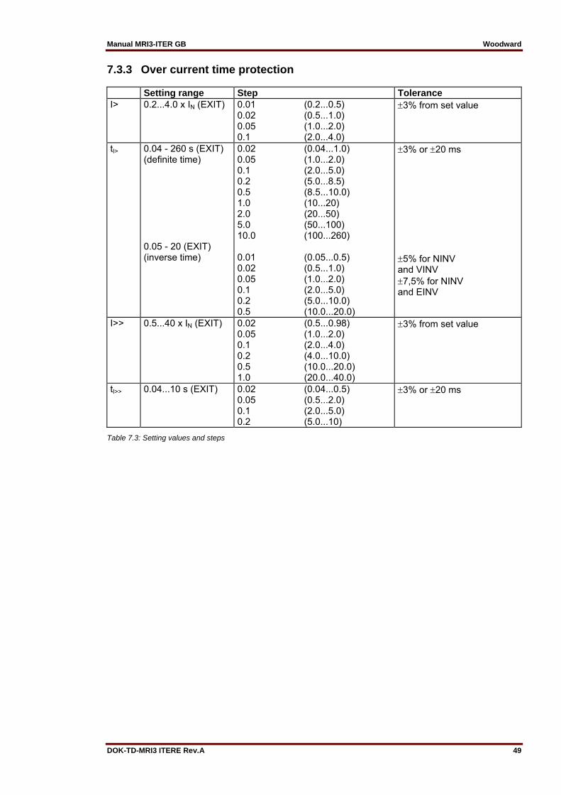
Manual MRI3-ITER GB Woodward
DOK-TD-MRI3 ITERE Rev.A 49
7.3.3 Over current time protection Setting range Step Tolerance I>
0.2...4.0 x IN (EXIT)
0.01 (0.2...0.5) 0.02 (0.5...1.0) 0.05 (1.0...2.0) 0.1 (2.0...4.0)
3% from set value
tI> 0.04 - 260 s (EXIT) (definite time) 0.05 - 20 (EXIT) (inverse time)
0.02 (0.04...1.0) 0.05 (1.0...2.0) 0.1 (2.0...5.0) 0.2 (5.0...8.5) 0.5 (8.5...10.0) 1.0 (10...20) 2.0 (20...50) 5.0 (50...100) 10.0 (100...260) 0.01 (0.05...0.5) 0.02 (0.5...1.0) 0.05 (1.0...2.0) 0.1 (2.0...5.0) 0.2 (5.0...10.0) 0.5 (10.0...20.0)
3% or 20 ms 5% for NINV and VINV 7,5% for NINV and EINV
I>>
0.5...40 x IN (EXIT)
0.02 (0.5...0.98) 0.05 (1.0...2.0) 0.1 (2.0...4.0) 0.2 (4.0...10.0) 0.5 (10.0...20.0) 1.0 (20.0...40.0)
3% from set value
tI>> 0.04...10 s (EXIT) 0.02 (0.04...0.5) 0.05 (0.5...2.0) 0.1 (2.0...5.0) 0.2 (5.0...10)
3% or 20 ms
Table 7.3: Setting values and steps
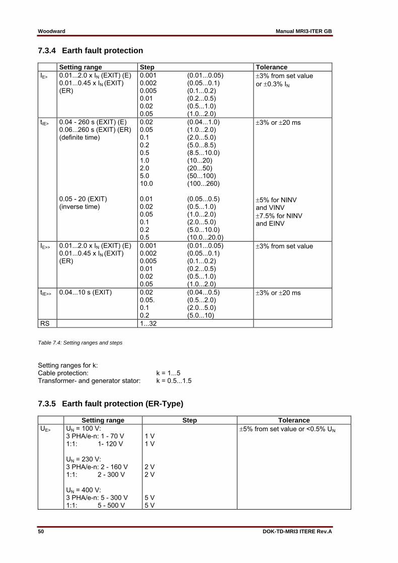
Woodward Manual MRI3-ITER GB
50 DOK-TD-MRI3 ITERE Rev.A
7.3.4 Earth fault protection Setting range Step Tolerance IE>
0.01...2.0 x IN (EXIT) (E) 0.01...0.45 x IN (EXIT) (ER)
0.001 (0.01...0.05) 0.002 (0.05...0.1) 0.005 (0.1...0.2) 0.01 (0.2...0.5) 0.02 (0.5...1.0) 0.05 (1.0...2.0)
3% from set value or 0.3% IN
tIE> 0.04 - 260 s (EXIT) (E) 0.06...260 s (EXIT) (ER) (definite time) 0.05 - 20 (EXIT) (inverse time)
0.02 (0.04...1.0) 0.05 (1.0...2.0) 0.1 (2.0...5.0) 0.2 (5.0...8.5) 0.5 (8.5...10.0) 1.0 (10...20) 2.0 (20...50) 5.0 (50...100) 10.0 (100...260) 0.01 (0.05...0.5) 0.02 (0.5...1.0) 0.05 (1.0...2.0) 0.1 (2.0...5.0) 0.2 (5.0...10.0) 0.5 (10.0...20.0)
3% or 20 ms 5% for NINV and VINV 7.5% for NINV and EINV
IE>>
0.01...2.0 x IN (EXIT) (E) 0.01...0.45 x IN (EXIT) (ER)
0.001 (0.01...0.05) 0.002 (0.05...0.1) 0.005 (0.1...0.2) 0.01 (0.2...0.5) 0.02 (0.5...1.0) 0.05 (1.0...2.0)
3% from set value
tIE>> 0.04...10 s (EXIT) 0.02 (0.04...0.5) 0.05. (0.5...2.0) 0.1 (2.0...5.0) 0.2 (5.0...10)
3% or 20 ms
RS 1...32
Table 7.4: Setting ranges and steps
Setting ranges for k: Cable protection: k = 1...5 Transformer- and generator stator: k = 0.5...1.5
7.3.5 Earth fault protection (ER-Type) Setting range Step Tolerance UE> UN = 100 V:
3 PHA/e-n: 1 - 70 V 1:1: 1- 120 V UN = 230 V: 3 PHA/e-n: 2 - 160 V 1:1: 2 - 300 V UN = 400 V: 3 PHA/e-n: 5 - 300 V 1:1: 5 - 500 V
1 V 1 V 2 V 2 V 5 V 5 V
5% from set value or <0.5% UN
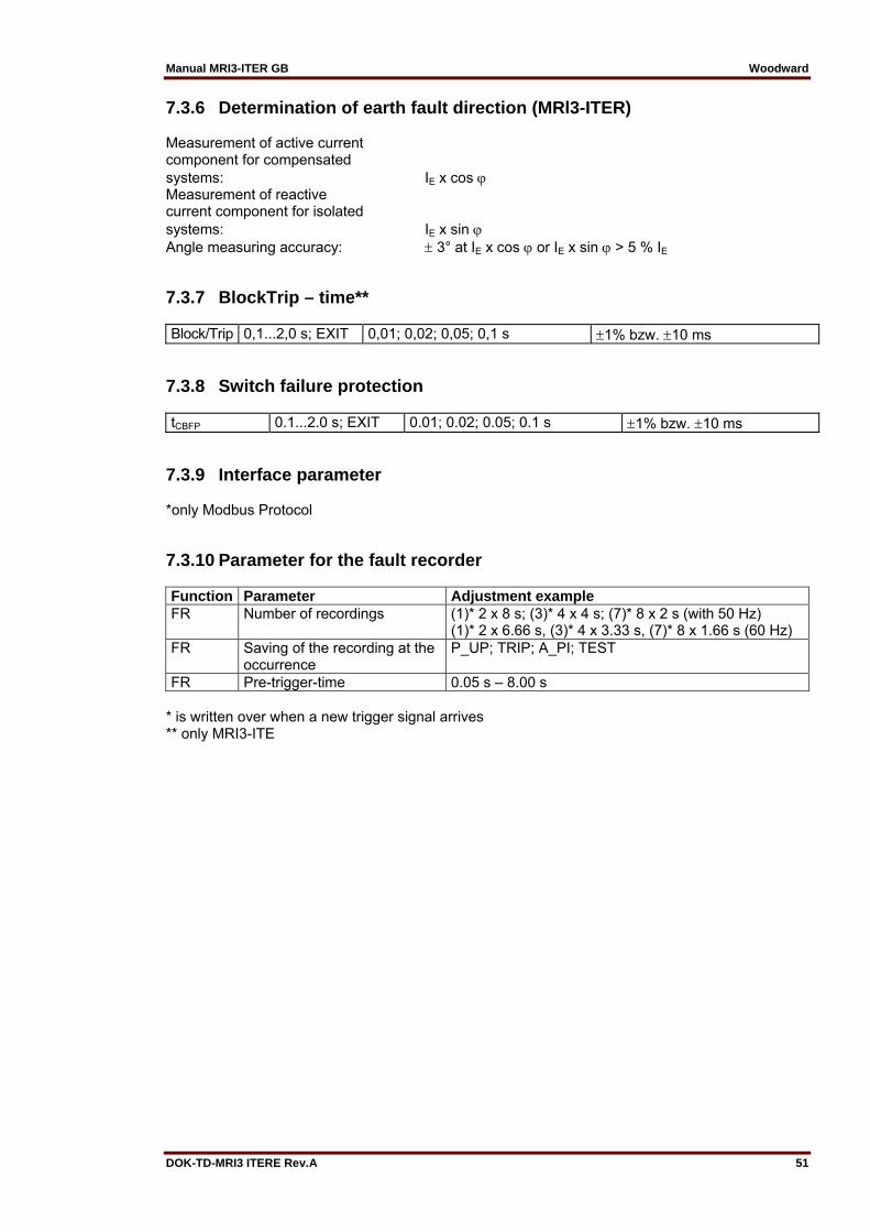
Manual MRI3-ITER GB Woodward
DOK-TD-MRI3 ITERE Rev.A 51
7.3.6 Determination of earth fault direction (MRl3-ITER) Measurement of active current component for compensated systems: IE x cos Measurement of reactive current component for isolated systems: IE x sin Angle measuring accuracy: 3° at IE x cos or IE x sin > 5 % IE
7.3.7 BlockTrip – time** Block/Trip 0,1...2,0 s; EXIT 0,01; 0,02; 0,05; 0,1 s 1% bzw. 10 ms
7.3.8 Switch failure protection tCBFP 0.1...2.0 s; EXIT 0.01; 0.02; 0.05; 0.1 s 1% bzw. 10 ms
7.3.9 Interface parameter *only Modbus Protocol
7.3.10 Parameter for the fault recorder Function Parameter Adjustment example FR Number of recordings (1)* 2 x 8 s; (3)* 4 x 4 s; (7)* 8 x 2 s (with 50 Hz)
(1)* 2 x 6.66 s, (3)* 4 x 3.33 s, (7)* 8 x 1.66 s (60 Hz) FR Saving of the recording at the
occurrence P_UP; TRIP; A_PI; TEST
FR Pre-trigger-time 0.05 s – 8.00 s * is written over when a new trigger signal arrives ** only MRI3-ITE

Woodward Manual MRI3-ITER GB
52 DOK-TD-MRI3 ITERE Rev.A
7.4 Tripping characteristics
7.4.1 Thermal characteristic From the equation for the temperature equivalent:
tI
k · IB· 100%
Ik · IB
· 100% · /
it is possible to deduce the tripping characteristics according to IEC 155-8. The temperature equivalent of the preload 0 equals the preload current IP:
IP
k · IB· 100%
Tripping is realized as soon as the temperature equivalent = k2 100% is reached. This tempera-ture equivalent equals a permanent load current of k IB :
Trip = k2 100% Trip = k2 100% For the tripping characteristic:
100%·
· 100%·
· 100%·
· 100%
or:
· · transpose to ettrip
k · lB ·
· In I I
l k · IB · In
llB
p
lIB
kmit p
llB
with The result are the tripping characteristics according to IEC 255-8:
·lB
lB
l
lBp k
with = thermal time constant of the object to be protected I = relay current IB = Basic current IP = preload current p = preload factor (p = 0 means cold condition of the electrical item) k = constant

Manual MRI3-ITER GB Woodward
DOK-TD-MRI3 ITERE Rev.A 53
7.4.2 Preload factor The normal tripping characteristic according to IEC 255-8:
· In
IIB
p
llB
k
Figure 7.1: Tripping characteristics for various preload factors p and constant k=1,0.
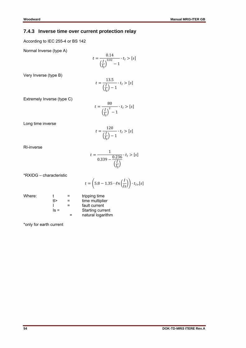
Woodward Manual MRI3-ITER GB
54 DOK-TD-MRI3 ITERE Rev.A
7.4.3 Inverse time over current protection relay According to IEC 255-4 or BS 142 Normal Inverse (type A)
0.14.
1·
Very Inverse (type B)
13.5
1·
Extremely Inverse (type C)
80
1·
Long time inverse
120
1·
RI-inverse
1
0.3390.236 ·
*RXIDG – characteristic
5.8 1.35 · ℓ ·
Where: t = tripping time tI> = time multiplier I = fault current Is = Starting current = natural logarithm *only for earth current

Manual MRI3-ITER GB Woodward
DOK-TD-MRI3 ITERE Rev.A 55
7.5 Tripping characteristics
Figure 7.2: Normal Inverse
Figure 7.3: Very Inverse
1 2 3 4 5 6 7 8 910 20I/IS
0.1
1
10
100
1000
t[s]
tI>=
0.05
0.1
0.2
0.30.40.50.60.81.0
1.4
2.0
3.04.0
6.08.010.0
1 2 3 4 5 6 7 8 910 20I/IS
0.1
1
10
100
1000
t[s]tI>=
0.05
0.1
0.2
0.30.40.50.60.81.0
10.0
1.4
2.0
3.04.0
6.08.0

Woodward Manual MRI3-ITER GB
56 DOK-TD-MRI3 ITERE Rev.A
Figure 7.4: Extremely Inverse
Figure 7.5: Definite time over current relay
1 2 3 4 5 6 7 8 910 20I/IS
0.01
0.1
1
10
100
1000
t[s]
tI>=
0.050.05 0.10.10.20.30.40.50.60.81.0
10.0
1.42.03.04.06.08.0
1 10I/IN
0.01
0.1
1
10
100
t[s]
tI>tI>
I>>I>>
tI>>tI>>
260260
0.030.03
1.01.0 40402.02.0
0.030.03
0.020.02 4.04.0I>I>
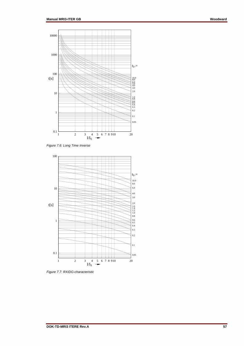
Manual MRI3-ITER GB Woodward
DOK-TD-MRI3 ITERE Rev.A 57
Figure 7.6: Long Time Inverse
Figure 7.7: RXIDG-characteristic
1 2 3 4 5 6 7 8 910 20I/IS
0.1
1
10
100
1000
10000
t[s]
tI>=
1.0
2.0
10.08.06.05.04.03.0
0.80.60.50.40.3
0.2
0.1
0.05
1 2 3 4 5 6 7 8 910 20I/IS
0.1
1
10
100
t[s]
tI>=
8.0
6.0
3.0
4.0
2.01.6
1.0
1.41.2
10.0
0.8
0.60.50.4
0.3
0.2
0.1
0.05
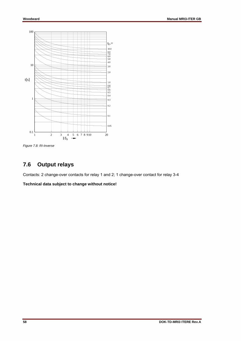
Woodward Manual MRI3-ITER GB
58 DOK-TD-MRI3 ITERE Rev.A
Figure 7.8: RI-Inverse
7.6 Output relays Contacts: 2 change-over contacts for relay 1 and 2; 1 change-over contact for relay 3-4 Technical data subject to change without notice!
1 2 3 4 5 6 7 8 910 20I/IS
0.1
1
10
100
t[s]
tI>=10.08.07.06.05.0
4.0
3.0
2.0
1.0
0.80.70.60.5
0.4
0.3
0.2
0.1
0.05

Manual MRI3-ITER GB Woodward
DOK-TD-MRI3 ITERE Rev.A 59
8. Order form
Time overcurrent-/earth fault current relay with thermal replica
MRI3-
T
3-phase current I>, I>> Rated current 1 A 5 A
I1 I5
Thermal replica Earth current none Rated current 1 A 5 A
* E1 E5
Directional feature in earth path none Rated voltage 100 V in earth path 230 V 400 V
* R1 R2 R4
Housing (12TE) 19“-rack Flush mounting
A D
Communication protocol RS485 Pro Open Data; Modbus RTU
* -M
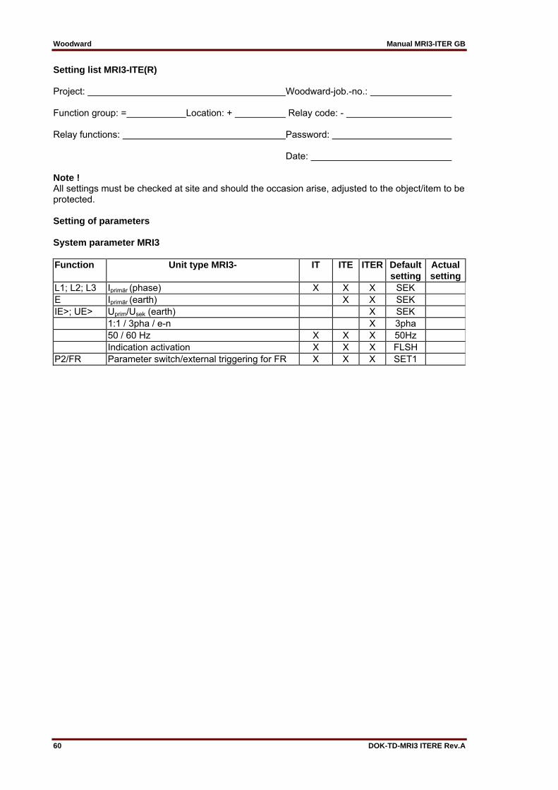
Woodward Manual MRI3-ITER GB
60 DOK-TD-MRI3 ITERE Rev.A
Setting list MRI3-ITE(R) Project: Woodward-job.-no.: Function group: = Location: + Relay code: - Relay functions: Password: Date: Note ! All settings must be checked at site and should the occasion arise, adjusted to the object/item to be protected. Setting of parameters System parameter MRI3 Function Unit type MRI3- IT ITE ITER Default Actual
setting setting L1; L2; L3 Iprimär (phase) X X X SEK E Iprimär (earth) X X SEK IE>; UE> Uprim/Usek (earth) X SEK 1:1 / 3pha / e-n X 3pha 50 / 60 Hz X X X 50Hz Indication activation X X X FLSH P2/FR Parameter switch/external triggering for FR X X X SET1

Manual MRI3-ITER GB Woodward
DOK-TD-MRI3 ITERE Rev.A 61
Parameter protection Function
Unit
IT ITE ITER Defaultsettings
Actual settings
2 parameter sets X X X Set 1/Set 2
Set 1
Set 2
IB,A Base current of the thermal over-load protection (low set element)
x IN X X X 0.40
kA Constant X X X 0.50 IB,A Energizing delay (time )for the
thermal overload s X X X 0.04
IB,T Base current of the thermal over-load protection (high set element)
x IN X X X 0.40
kT Constant X X X 0.50 IB,T Energizing delay (time )for the
thermal overload s X X X 0.04
C Time constant (cooling down) min X X X 0.5 W Time constant (warming up) min X X X 0.5 I> Pickup value for phase overcur-
rent x IN X X X 0.20
CHAR I> Tripping characteristic for phase overcurrent element
X X X DEFT
tI> Trip delay for phase overcurrent element
(s) X X X 0.06
I>+CHARI> Reset Modus X X X I>> Pickup value for overcurrent high
set element x IN X X X 1.00
tI>> Trip delay for overcurrent high set element
s X X X 0.06
1:1/3pha/e-n Residual voltage measuring X 3pha UE Pickup value for residual voltage V X 1/2/5 IE> Pickup value for earth fault low
set element x IN X X 0.01
WARN/TRIP Warning/tripping setting X X TRIP CHAR IE Tripping characteristic for earth
fault overcurrent element X DEFT
tIE> Trip delay for earth fault overcur-rent elemnt
(s) X X 0.06
IE>+CHAR I>
Reset Mode s X 0
IE>> Pickup value for earth fault high set element
x IN X X 0.01
tIE>> Trip delay for earth fault high set element
s X X 0.06
SIN/COS SIN/COS - setting X SIN Block/Trip Block/trip - time s X X EXIT tCBFP Trip time circuit breaker failure
protection X X X X EXIT
RS* Baud-Rate of serial interface X X X 9600 RS* Parity check of serial interface X X X even RS Slave Address of serial interface X X X 1
*only Modbus Protocol
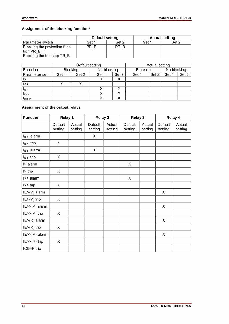
Woodward Manual MRI3-ITER GB
62 DOK-TD-MRI3 ITERE Rev.A
Assignment of the blocking function* Default setting Actual setting Parameter switch Set 1 Set 2 Set 1 Set 2 Blocking the protection func-tion PR_B
PR_B PR_B
Blocking the trip step TR_B Default setting Actual setting Function Blocking No blocking Blocking No blocking Parameter set Set 1 Set 2 Set 1 Set 2 Set 1 Set 2 Set 1 Set 2 I> X X I>> X X IE> X X IE>> X X tCBFP X X
Assignment of the output relays
Function Relay 1 Relay 2 Relay 3 Relay 4
Default setting
Actual setting
Default setting
Actual setting
Default setting
Actual setting
Default setting
Actual setting
IB,A alarm X
IB,A trip X
IB,T alarm X
IB,T trip X
I> alarm X
I> trip X
I>> alarm X
I>> trip X
IE>(V) alarm X
IE>(V) trip X
IE>>(V) alarm X
IE>>(V) trip X
IE>(R) alarm X
IE>(R) trip X
IE>>(R) alarm X
IE>>(R) trip X
tCBFP trip

Manual MRI3-ITER GB Woodward
DOK-TD-MRI3 ITERE Rev.A 63
Parameter for the fault recorder Default ActualFunction Unit settings set-
tingsFR Number of recordings 4 FR Saving of the recording at the occurrence TRIP FR Time prior to trigger impulse s 0.05 Year settings Year Y=00
Month settings Month M=00
Day settings Day D=00
Setting of the hour Hour h=00
Setting of the minute Minute m=00
Setting of the second Second s=00
Setting of code jumpers
Code jumper J1 J2 J3
Default set-ting
Actual set-ting
Default set-ting
Actual set-ting
Default set-ting
Actual setting
Plugged
Not plugged X No function X
Code jumper Low/High-range for Reset Input Low/High-range for blockage in-put
Default setting Actual setting Default setting Actual setting
Low=plugged X X
High=not plugged
This technical manual is valid for the software version: D21-2.06 (MRI3-IT-ITE) D30-2.06 (MRI3-ITER) Modbus Protocol Software version D71-1.05 (MRI3-IT-M/-ITE-M) D80-1.05 (MRI3-ITER-M)

Woodward Manual MRI3-ITER GB
64 DOK-TD-MRI3 ITERE Rev.A
Woodward Kempen GmbH Krefelder Weg 47 D – 47906 Kempen (Germany)
Postfach 10 07 55 (P.O.Box) D – 47884 Kempen (Germany) Phone: +49 (0) 21 52 145 1
Internet
www.woodward.com
Sales Phone: +49 (0) 21 52 145 216 or 342 Telefax: +49 (0) 21 52 145 354
e-mail: [email protected]
Service Phone: +49 (0) 21 52 145 614 Telefax: +49 (0) 21 52 145 455
e-mail: [email protected]