Embed Size (px)
Citation preview

SH (NA) 030035-B (0701) MEE Printed in Japan Specifications subject to change without notice.This Instruction Manual uses recycled paper.
MODEL
MODELCODE
General-Purpose AC Servo
MR-J2S- B-PY096MR-J2S- B-S096(5.7kW)
MODEL
INSTRUCTION MANUAL
SSCNET Fully Closed Control Compatible
J2-Super Series
J2-Su
per S
eriesM
R-J2S
- B-P
Y096 M
R-J2S
- B-S
096(5.7kW) In
structio
n M
anu
al
HEAD OFFICE : TOKYO BLDG MARUNOUCHI TOKYO 100-8310
B
B

A - 1
Safety Instructions (Always read these instructions before using the equipment.)
Do not attempt to install, operate, maintain or inspect the servo amplifier and servo motor until you have readthrough this Instruction Manual, Installation guide, Servo motor Instruction Manual and appended documentscarefully and can use the equipment correctly. Do not use the servo amplifier and servo motor until you have afull knowledge of the equipment, safety information and instructions.In this Instruction Manual, the safety instruction levels are classified into "WARNING" and "CAUTION".
WARNING Indicates that incorrect handling may cause hazardous conditions,resulting in death or severe injury.
CAUTION Indicates that incorrect handling may cause hazardous conditions,resulting in medium or slight injury to personnel or may cause physicaldamage.
Note that the CAUTION level may lead to a serious consequence according to conditions. Please follow theinstructions of both levels because they are important to personnel safety.What must not be done and what must be done are indicated by the following diagrammatic symbols:
: Indicates what must not be done. For example, "No Fire" is indicated by .
: Indicates what must be done. For example, grounding is indicated by .
In this Instruction Manual, instructions at a lower level than the above, instructions for other functions, and soon are classified into "POINT".After reading this Instruction Manual, always keep it accessible to the operator.

A - 2
1. To prevent electric shock, note the following:
WARNINGBefore wiring or inspection, switch power off and wait for more than 15 minutes. Then, confirm the voltageis safe with voltage tester. Otherwise, you may get an electric shock.
Connect the servo amplifier and servo motor to ground.
Any person who is involved in wiring and inspection should be fully competent to do the work.
Do not attempt to wire the servo amplifier and servo motor until they have been installed. Otherwise, youmay get an electric shock.
Operate the switches with dry hand to prevent an electric shock.
The cables should not be damaged, stressed, loaded, or pinched. Otherwise, you may get an electric shock.
During power-on or operation, do not open the front cover. You may get an electric shock.
Do not operate the converter unit and servo amplifier with the front cover removed. High-voltage terminalsand charging area are exposed and you may get an electric shock.
Except for wiring or periodic inspection, do not remove the front cover even if the power is off. The servoamplifier is charged and you may get an electric shock.
2. To prevent fire, note the following:
CAUTIONInstall the converter unit and servo amplifier, servo motor and regenerative resistor on incombustiblematerial. Installing them directly or close to combustibles will lead to a fire.
When the servo amplifier has become faulty, switch off the main servo amplifier power side. Continuousflow of a large current may cause a fire.
When a regenerative resistor is used, use an alarm signal to switch main power off. Otherwise, aregenerative transistor fault or the like may overheat the regenerative resistor, causing a fire.
3. To prevent injury, note the follow
CAUTIONOnly the voltage specified in the Instruction Manual should be applied to each terminal. Otherwise, a burst,damage, etc. may occur.
Connect the terminals correctly to prevent a burst, damage, etc.
Ensure that polarity ( , ) is correct. Otherwise, a burst, damage, etc. may occur.
During power-on or for some time after power-off, do not touch or close a parts (cable etc.) to the servoamplifier heat sink, regenerative resistor, servo motor, etc. Their temperatures may be high and you mayget burnt or a parts may damaged.
During operation, never touch the rotating parts of the servo motor. Doing so can cause injury.

A - 3
4. Additional instructionsThe following instructions should also be fully noted. Incorrect handling may cause a fault, injury, electricshock, etc.
(1) Transportation and installation
CAUTIONTransport the products correctly according to their weights.Stacking in excess of the specified number of products is not allowed.Do not carry the servo motor by the cables, shaft or encoder.Do not hold the front cover to transport the controller. The controller may drop.Install the servo amplifier in a load-bearing place in accordance with the Instruction Manual.Do not climb or stand on servo equipment. Do not put heavy objects on equipment.The controller and servo motor must be installed in the specified direction.Leave specified clearances between the servo amplifier and control enclosure walls or other equipment.Do not install or operate the servo amplifier and servo motor which has been damaged or has any partsmissing.Provide adequate protection to prevent screws and other conductive matter, oil and other combustiblematter from entering the servo amplifier and servo motor.Do not drop or strike servo amplifier or servo motor. Isolate from all impact loads.When you keep or use it, please fulfill the following environmental conditions.
ConditionsEnvironmentServo amplifier Servo motor
[ ] 0 to 55 (non-freezing) 0 to 40 (non-freezing)Operation[ ] 32 to 131 (non-freezing) 32 to 104 (non-freezing)[ ] 20 to 65 (non-freezing) 15 to 70 (non-freezing)
Ambienttemperature
Storage [ ] 4 to 149 (non-freezing) 5 to 158 (non-freezing)Operation 90%RH or less (non-condensing) 80%RH or less (non-condensing)Ambient
humidity Storage 90%RH or less (non-condensing)Ambience Indoors (no direct sunlight) Free from corrosive gas, flammable gas, oil mist, dust and dirtAltitude Max. 1000m (3280 ft) above sea level
HC-KFS SeriesHC-MFS SeriesHC-UFS13 to 73
X Y : 49
HC-SFS81HC-SFS52 to 152HC-SFS53 to 153HC-RFS Series
HC-UFS 72 152
X Y : 24.5
HC-SFS121 201HC-SFS202 352HC-SFS203 353HC-UFS202 to 502
X : 24.5Y : 49
HC-SFS301HC-SFS502 to 702
X : 24.5Y : 29.4
[m/s2] 5.9 or less
HA-LFS11K2 to 22K2 X : 11.7Y : 29.4
HC-KFS SeriesHC-MFS Series
HC-UFS 13 to 73X Y : 161
HC-SFS81HC-SFS52 to 152HC-SFS53 to 153HC-RFS Series
HC-UFS 72 152
X Y : 80
HC-SFS121 201HC-SFS202 352HC-SFS203 353HC-UFS202 to 502
X : 80Y : 161
HC-SFS301HC-SFS502 to 702
X : 80Y : 96
(Note)Vibration
[ft/s2] 19.4 or less
HA-LFS11K2 to 22K2 X : 38Y : 96
Note. Except the servo motor with reduction gear.

A - 4
CAUTIONSecurely attach the servo motor to the machine. If attach insecurely, the servo motor may come off duringoperation.
The servo motor with reduction gear must be installed in the specified direction to prevent oil leakage.
Take safety measures, e.g. provide covers, to prevent accidental access to the rotating parts of the servomotor during operation.
Never hit the servo motor or shaft, especially when coupling the servo motor to the machine. The encodermay become faulty.
Do not subject the servo motor shaft to more than the permissible load. Otherwise, the shaft may break.
When the equipment has been stored for an extended period of time, consult Mitsubishi.
(2) Wiring
CAUTIONWire the equipment correctly and securely. Otherwise, the servo motor may misoperate.
Do not install a power capacitor, surge absorber or radio noise filter (FR-BIF option) between the servomotor and servo amplifier.
Connect the output terminals (U, V, W) correctly. Otherwise, the servo motor will operate improperly.
Connect the servo motor power terminal (U, V, W) to the servo motor power input terminal (U, V, W)directly. Do not let a magnetic contactor, etc. intervene.
U
Servo Motor
MV
W
U
V
W
U
MV
W
U
V
W
Servo Amplifier(drive unit) Servo Motor
Servo Amplifier(drive unit)
Do not connect AC power directly to the servo motor. Otherwise, a fault may occur.
The surge absorbing diode installed on the DC output signal of the servo amplifier relay must be wired inthe specified direction. Otherwise, the forced stop (EM1) and other protective circuits may not operate.
COM(24VDC)
ServoAmplifier
RA
ControloutputsignalRA
ServoAmplifier
COM(24VDC)
Controloutputsignal

A - 5
(3) Test run adjustment
CAUTIONBefore operation, check the parameter settings. Improper settings may cause some machines to performunexpected operation.
The parameter settings must not be changed excessively. Operation will be insatiable.
(4) Usage
CAUTIONProvide a forced stop circuit to ensure that operation can be stopped and power switched off immediately.
Any person who is involved in disassembly and repair should be fully competent to do the work.
Before resetting an alarm, make sure that the run signal of the servo amplifier is off to prevent anaccident. A sudden restart is made if an alarm is reset with the run signal on.
Do not modify the equipment.
Use a noise filter, etc. to minimize the influence of electromagnetic interference, which may be caused byelectronic equipment used near the servo amplifier.
Burning or breaking a servo amplifier may cause a toxic gas. Do not burn or break a servo amplifier.
Use the servo amplifier with the specified servo motor.
The electromagnetic brake on the servo motor is designed to hold the motor shaft and should not be usedfor ordinary braking.
For such reasons as service life and mechanical structure (e.g. where a ballscrew and the servo motorare coupled via a timing belt), the electromagnetic brake may not hold the motor shaft. To ensure safety,install a stopper on the machine side.
(5) Corrective actions
CAUTIONWhen it is assumed that a hazardous condition may take place at the occur due to a power failure or aproduct fault, use a servo motor with electromagnetic brake or an external brake mechanism for thepurpose of prevention.
Configure the electromagnetic brake circuit so that it is activated not only by the interface unit signals butalso by a forced stop (EM1).
EM1RA
24VDC
Contacts must be open whenservo-off, when an alarm occurrenceand when an electromagnetic brake interlock (MBR).
Electromagnetic brake
Servo motor
Circuit must be opened duringforced stop (EM1).

A - 6
CAUTIONWhen any alarm has occurred, eliminate its cause, ensure safety, and deactivate the alarm beforerestarting operation.
When power is restored after an instantaneous power failure, keep away from the machine because themachine may be restarted suddenly (design the machine so that it is secured against hazard if restarted).
(6) Maintenance, inspection and parts replacement
CAUTIONWith age, the electrolytic capacitor of the servo amplifier will deteriorate. To prevent a secondary accidentdue to a fault, it is recommended to replace the electrolytic capacitor every 10 years when used in generalenvironment. Please consult our sales representative.
(7) General instruction
To illustrate details, the equipment in the diagrams of this Instruction Manual may have been drawnwithout covers and safety guards. When the equipment is operated, the covers and safety guards mustbe installed as specified. Operation must be performed in accordance with this Instruction Manual.
About processing of waste When you discard servo amplifier, a battery (primary battery), and other option articles, please follow the law ofeach country (area).
FOR MAXIMUM SAFETYThese products have been manufactured as a general-purpose part for general industries, and have notbeen designed or manufactured to be incorporated in a device or system used in purposes related tohuman life.Before using the products for special purposes such as nuclear power, electric power, aerospace,medicine, passenger movement vehicles or under water relays, contact Mitsubishi.
These products have been manufactured under strict quality control. However, when installing the productwhere major accidents or losses could occur if the product fails, install appropriate backup or failsafefunctions in the system.
EEP-ROM lifeThe number of write times to the EEP-ROM, which stores parameter settings, etc., is limited to 100,000. Ifthe total number of the following operations exceeds 100,000, the servo amplifier and/or converter unit mayfail when the EEP-ROM reaches the end of its useful life.
Write to the EEP-ROM due to parameter setting changes
Precautions for Choosing the ProductsMitsubishi will not be held liable for damage caused by factors found not to be the cause of Mitsubishi;machine damage or lost profits caused by faults in the Mitsubishi products; damage, secondary damage,accident compensation caused by special factors unpredictable by Mitsubishi; damages to products otherthan Mitsubishi products; and to other duties.

A - 7
COMPLIANCE WITH EC DIRECTIVES1. WHAT ARE EC DIRECTIVES?The EC directives were issued to standardize the regulations of the EU countries and ensure smoothdistribution of safety-guaranteed products. In the EU countries, the machinery directive (effective inJanuary, 1995), EMC directive (effective in January, 1996) and low voltage directive (effective in January,1997) of the EC directives require that products to be sold should meet their fundamental safetyrequirements and carry the CE marks (CE marking). CE marking applies to machines and equipmentinto which servo amplifiers have been installed.(1) EMC directive
The EMC directive applies not to the servo units alone but to servo-incorporated machines andequipment. This requires the EMC filters to be used with the servo-incorporated machines andequipment to comply with the EMC directive. For specific EMC directive conforming methods, refer tothe EMC Installation Guidelines (IB(NA)67310).
(2) Low voltage directiveThe low voltage directive applies also to servo units alone. Hence, they are designed to comply withthe low voltage directive.This servo is certified by TUV, third-party assessment organization, to comply with the low voltagedirective.
(3) Machine directiveNot being machines, the servo amplifiers need not comply with this directive.
2. PRECAUTIONS FOR COMPLIANCE(1) Servo amplifiers and servo motors used
Use the servo amplifiers and servo motors which comply with the standard model.
Servo amplifier :MR-J2S-10B-PY096 to MR-J2S-350B-PY096MR-J2S-500B-S096 to MR-J2S-700B-S096
MR-J2S-10B1-PY096 to MR-J2S-40B1-PY096Servo motor :HC-KFS
HC-MFS HC-SFS HC-RFS HC-UFS HA-LFS HC-LFS
(2) Configuration
Reinforcedinsulatingtransformer
NFB MC SM
No-fusebreaker
Magneticcontactor
Reinforcedinsulating type
24VDCpowersupply
Servoamplifier
Servomotor
Control box
(Note)
Note. The insulating transformer is not required for the 11kW or more servo amplifier.
(3) EnvironmentOperate the servo amplifier at or above the contamination level 2 set forth in IEC664. For thispurpose, install the servo amplifier in a control box which is protected against water, oil, carbon, dust,dirt, etc. (IP54).
A - 8
(4) Power supply(a) Operate the servo amplifier 7kW or less to meet the requirements of the overvoltage category II set
forth in IEC664. For this purpose, a reinforced insulating transformer conforming to the IEC or ENstandard should be used in the power input section.Since the 11kW or more servo amplifier can be used under the conditions of the overvoltagecategory III set forth in IE644, a reinforced insulating transformer is not required in the powerinput section.
(b) When supplying interface power from external, use a 24VDC power supply which has beeninsulation-reinforced in I/O.
(5) Grounding(a) To prevent an electric shock, always connect the protective earth (PE) terminals (marked ) of the
servo amplifier to the protective earth (PE) of the control box.
(b) Do not connect two ground cables to the same protective earth (PE) terminal Always connect thecables to the terminals one-to-one.
PE terminals PE terminals
(c) If a leakage current breaker is used to prevent an electric shock, the protective earth (PE)terminals of the servo amplifier must be connected to the corresponding earth terminals.
(6) Wiring(a) The cables to be connected to the terminal block of the servo amplifier must have crimping
terminals provided with insulating tubes to prevent contact with adjacent terminals.
Crimping terminal
Insulating tube
Cable
(b) Use the servo motor side power connector which complies with the EN Standard. The EN Standardcompliant power connector sets are available from us as options.
(7) Auxiliary equipment and options(a) The no-fuse breaker and magnetic contactor used should be the EN or IEC standard-compliant
products of the models described in Section 12.2.2.
(b) The sizes of the cables described in Section 12.2.1 meet the following requirements. To meet theother requirements, follow Table 5 and Appendix C in EN60204-1.
Ambient temperature: 40 (104) [ ( )]Sheath: PVC (polyvinyl chloride)Installed on wall surface or open table tray
(c) Use the EMC filter for noise reduction.

A - 9
(8) Performing EMC testsWhen EMC tests are run on a machine/device into which the servo amplifier has been installed, itmust conform to the electromagnetic compatibility (immunity/emission) standards after it hassatisfied the operating environment/electrical equipment specifications.For the other EMC directive guidelines on the servo amplifier, refer to the EMC InstallationGuidelines(IB(NA)67310).
CONFORMANCE WITH UL/C-UL STANDARD(1) Servo amplifiers and servo motors used
Use the servo amplifiers and servo motors which comply with the standard model.
Servo amplifier :MR-J2S-10B-PY096 to MR-J2S-350B-PY096MR-J2S-500B-S096 to MR-J2S-700B-S096
MR-J2S-10B1-PY096 to MR-J2S-40B1-PY096Servo motor :HC-KFS
HC-MFS HC-SFS HC-RFS HC-UFS HA-LFS HC-LFS
(2) InstallationInstall a cooling fan of 100CFM (2.8m3/min) air flow 4 in (10.16 cm) above the servo amplifier orprovide cooling of at least equivalent capability.
(3) Short circuit ratingThis servo amplifier conforms to the circuit whose peak current is limited to 5000A or less. Havingbeen subjected to the short-circuit tests of the UL in the alternating-current circuit, the servoamplifier conforms to the above circuit.
(4) Capacitor discharge timeThe capacitor discharge time is as listed below. To ensure safety, do not touch the charging section for15 minutes after power-off.
Servo amplifier Discharge time[min]
MR-J2S-10B(1) 20B(1) 1MR-J2S-40B(1) 60B 2MR-J2S-70B to 350B 3MR-J2S-500B 700B 5
MR-J2S-11KB 4MR-J2S-15KB 6MR-J2S-22KB 8
(5) Options and auxiliary equipmentUse UL/C-UL standard-compliant products.

A - 10
(6) Attachment of a servo motorFor the flange size of the machine side where the servo motor is installed, refer to "CONFORMANCEWITH UL/C-UL STANDARD" in the Servo Motor Instruction Manual.
(7) About wiring protectionFor installation in United States, branch circuit protection must be provided, in accordance with theNational Electrical Code and any applicable local codes.For installation in Canada, branch circuit protection must be provided, in accordance with the CanadaElectrical Code and any applicable provincial codes.
1
CONTENTS
1. FUNCTIONS AND CONFIGURATION 1- 1 to 1- 6
1.1 Overview................................................................................................................................................... 1- 11.2 Control block diagram............................................................................................................................. 1- 21.3 Specification list....................................................................................................................................... 1- 31.4 Model name.............................................................................................................................................. 1- 31.5 System configuration............................................................................................................................... 1- 4
2. LINEAR SCALES 2- 1 to 2-30
2.1 Compatible linear scale list .................................................................................................................... 2- 12.1.1 Mitutoyo make linear scales (ABS type) ........................................................................................ 2- 22.1.2 Heidenhain make linear encoder (linear scale) (ABS type) ......................................................... 2- 92.1.3 Renishaw make linear encoders (linear scales) (INC type)......................................................... 2-152.1.4 Sony precision technology make linear encoders (linear scales) (INC type) ............................. 2-21
2.2 A B Z-phase differential input Interface unit specifications.......................................................... 2-27
3. SIGNALS AND WIRING 3- 1 to 3- 6
3.1 Standard connection examples of full closed control servo amplifier control signals....................... 3- 13.2 Signal terminal explanation................................................................................................................. 3- 53.3 About power-on........................................................................................................................................ 3- 6
4. OPERATION AND FUNCTIONS 4- 1 to 4-22
4.1 Startup...................................................................................................................................................... 4- 14.1.1 Startup procedure............................................................................................................................. 4- 14.1.2 Selection of full closed function ....................................................................................................... 4- 24.1.3 Selection of full closed encoder communication system................................................................ 4- 34.1.4 Setting of full closed encoder polarity............................................................................................. 4- 44.1.5 Setting of full closed encoder electronic gear ................................................................................. 4- 54.1.6 Confirmation of full closed encoder position data ......................................................................... 4- 64.1.7 Setting of dual feedback switching filter........................................................................................ 4- 7
4.2 Home position return operation............................................................................................................. 4- 84.2.1 General precautions ......................................................................................................................... 4- 84.2.2 Full closed encoder types and home position return methods ..................................................... 4- 8
4.3 Operation from controller ...................................................................................................................... 4-154.3.1 Operation from controller ............................................................................................................... 4-154.3.2 Controller setting............................................................................................................................. 4-15
4.4 Functions................................................................................................................................................. 4-174.4.1 Full closed control error detection.................................................................................................. 4-174.4.2 Auto tuning function ....................................................................................................................... 4-184.4.3 Machine analyzer function ............................................................................................................. 4-184.4.4 Test operation .................................................................................................................................. 4-18
4.5 Absolute position detection system....................................................................................................... 4-19

2
4.6 About the MR Configurator................................................................................................................... 4-204.6.1 When current version of MR Configurator (MRZJW3-SETUP121 to -SETUP151 S/W: E0 version) is used ................................................. 4-204.6.2 When full closed compatible MR Configurator (MRZJW3-SETUP151 S/W: E1 version or later) is used ............................................................. 4-21
5. PARAMETERS 5- 1 to 5- 8
5.1 Parameter list ...................................................................................................................................... 5- 1
6. TROUBLESHOOTING 6- 1 to 6- 2
6.1 Alarm list.................................................................................................................................................. 6- 16.2 Scale error (AL. 2A) details classified by linear scale manufacturer ................................................. 6- 2
7. OPTIONS AND AUXILIARY EQUIPMENT 7- 1 to 7- 2
7.1 CN2 wiring option cable (MR-J2SCLCBL02M-P-H) ........................................................................... 7- 1

1 - 1
1. FUNCTIONS AND CONFIGURATION
1 FUNCTIONS AND CONFIGURATION
1.1 Overview
This Instruction Manual explains the product that imports a position F/B signal from a full closedencoder, such as a linear scale, to the MR-J2S-B servo amplifier to perform full closed control.For the items not described in this Instruction Manual, refer to the MELSERVO-J2S-B Specifications andInstallation Guide and Instruction Manual since they are the same as those of the standard model.For the specifications of the A B Z differential input I/F unit MR-J2S-CLP01, refer to the MR-J2S-CLP01 Installation Guide.
[Items changed from those of the standard model]1) The A B Z differential input I/F unit MR-J2S-CLP01 or Mitsubishi serial interface compatible
linear scale is used to detect the position F/B signal of a full closed encoder such as a linear scale.2) In addition to the full closed control that feeds back the position signal of the full closed encoder,
dual F/B control that feeds back a signal composed of the full closed encoder's position F/B signaland the motor position F/B signal has been added as an extended function.
3) Function to switch pulse output between the full closed encoder and motor end encoder4) Addition of restriction on the RS232C communication baud rate (enabled for 9600bps only)
[Functions deleted from the standard model]1) Speed torque control2) Motor-less operation (test operation)

1 - 2
1. FUNCTIONS AND CONFIGURATION
1.2 Control block diagram
A full closed control block diagram is shown below.
Controller
Command pulsetrain electronic gearParameter No. 6Full closed selectionParameter No. 62(Note 1, 2)Dual F/B filterParameter No. 67(Note 2)
In-position judgmentINP
Command pulse unit
1
CMX
CMX1
S
Dual f/b position signal
Position deviation
Encoder pulse unit
FCM
FCD
FCD
FCM
Servo motor
Linear scale
OP9
FCT
Closed end pulse unit
ABZ phase pulseoutput selectionParameter No. 68Full closed control errordetection function selectionParameter No. 62, 63, 64
Full closed electronic gearParameter No. 65, 66
Droop pulses (MR Configurator display, analog monitor)
Droop pulse unitselectionParameter No. 68
Full closed control block diagram
S
Note 1. Switching between semi closed control and full closed control can be performed by changing the setting of parameter No. 62.When semi closed control is selected, control is always performed on the basis of the position data of the motor end encoder(independently of whether the motor is at a stop or running).
2. When parameter No. 62 "full closed function" is valid, dual F/B control in which the motor F/B signal and full closed encoder F/Bsignal are combined by the dual F/B filter in parameter No. 67 is performed.In this case, full closed control is performed when the motor is at a stop, and semi closed control is performed when the motoris operating to improve control performance. When 1000 is set as the filter value of parameter No. 67, full closed control isalways performed.
Control Mode Item Description
Feature Position is controlled according to the motor end data.
AdvantageSince this control is insusceptible to machine influence (such asmachine resonance), the gains of the servo amplifier can beraised and the settling time shortened.
Semi closed control
DisadvantageIf the motor end is at a stop, the machine end may be vibratingor the machine end accuracy not obtained.
FeaturePosition is controlled according to the motor end data andmachine end data.
Advantage
Control is performed according to the motor end data duringoperation, and according to the machine end data at a stop insequence to raise the gains during operation and shorten thesettling time.A stop is made with the machine end accuracy.
Dual F/B control
Disadvantage No specific disadvantage.Feature Position is controlled according to the machine end data.
AdvantageThe machine end accuracy is obtained not only at a stop but alsoduring operation.
Full closed control
DisadvantageSince this control is susceptible to machine influence (such asmachine resonance), the gains of the servo amplifier do not riseand the settling time increases.

1 - 3
1. FUNCTIONS AND CONFIGURATION
1.3 Specification list
(1) Servo amplifiers
Servo Amplifier ModelMR-J2S-
10B
-PY096
20B
-PY096
40B
-PY096
60B
-PY096
70B
-PY096
100B
-PY096
200B
-PY096
350B
-PY096
500B
-S096
700B
-S096
10B1
-PY096
20B1
-PY096
40B1
-PY096
Voltage frequency(Note 1)
Three-phase 200 to 230VAC/50, 60Hzor single-phase 230VAC/50, 60Hz
(Note 2)
Three-phase 200 to 230VAC/50, 60Hz(Note 2)
Single-phase 100 to120VAC/50, 60Hz
Permissible voltagefluctuation
Three-phase 170 to 253VAC/50, 60Hzor single-phase 207 to 253VAC/50,
60HzThree-phase 170 to 253VAC/50, 60Hz
Single-phase 85 to127VAC/50, 60Hz
Powersupply
Permissiblefrequencyfluctuation
Within 5%
Control system Sine-wave PWM control current control system
Protective functionsOvercurrent shutoff, regenerative overvoltage shutoff, overload shutoff (electronic thermal relay),
servo motor overheat protection, encoder error protection, regeneration error protection,undervoltage instantaneous power supply protection, overspeed protection, error excessive protection
Structure Self-cooling, open (IP00) Forced cooling, open (IP00)Self-cooling,open (IP00)
Ambienttemperature
0 to 55 (non-freezing), storage: 20 to 65 (non-freezing)
Ambienthumidity
90%RH or less (non-condensing), storage: 90%RH or less (non-condensing)
Ambience Indoors (no direct sunlight), without corrosive gas flammable gas oil mist dust and dirtAltitude 1000m or less above sea level
Environment
Vibration 5.9m/s2 or lessWeight (kg) 0.7 0.7 1.1 1.1 1.7 1.7 2.0 2.0 4.9 7.2 0.7 0.7 1.1
Note 1. The rated output capacity and rated speed of a servo motor used with the servo amplifier assumes that the power supplyvoltage and frequency are as indicated. They cannot be guaranteed when a power supply voltage drop occurs.
2. The torque characteristic of the servo amplifier used with a servo motor assumes that the voltage is three-phase 200 to 230VACor single-phase 230VAC.
1.4 Model name
MR-J2S B 1
1020406070100
200
350500700
053, 132343
73 73
4323
053, 13
52, 53
81, 102, 103121, 201, 152,202, 153, 203301, 352, 353
502702
353, 503203 202
352, 502
103, 153 152
72, 73
132343
HC-KFS HC-MFS HC-SFS HC-RFS HC-UFS
Mitsubishi general-purposeAC servo amplifier series name
Compatible motor list
B: SSCNET compatibility
Symbol
Note. The standard specifications comply with the EN, UL and cUL Standards.
Symbol Power supply
None
1
Three-phase 200VACor single-phase230VAC (Note 1)
Single-phase 100VAC(Note 2)
Note: 1. Single-phase 230VAC is for only the servo amplifier of MR-J2S-70 or less. 2. For only the servo amplifier of MR-J2S-40 or less.
Symbol
PY096
S096
Full closed controlcompatible amplifier
MR-J2S-B type0.05 to 3.5kw
MR-J2S-B type5.0, 7.0kw
PY096

1 - 4
1. FUNCTIONS AND CONFIGURATION
1.5 System configuration
(1) When A B Z differential input interface unit (MR-J2S-CLP01) is usedThe A B Z differential input interface unit (MR-J2S-CLP01) converts external ABZ phase pulsesinto a position feedback signal that can be used for serial communication.Full closed control is enabled by connecting the output of the MR-J2S-CLP01 to the servo amplifierencoder connector.
CAUTIONWhen the MR-J2S-CLP01 is used, a linear scale without Z phase cannot beconnected. Use a linear scale that has the Z phase.
System configuration example 1 (when ABZ pulse train-specified linear scale is used)
SSCNET controller
Servo amplifier
Positioncommandcontrol signal
CN1A
CN1B
CN2
CN2
SSCNET
Encoder signal Linear scale
A, B, Z phase output (ALM output)
ABZ differential input I/F unit
Servo motor
To otheraxis
General-purpose pulse output linear scaleMR-J2S-CLP01
Note 1. A linear scale without Z phase cannot be connected.2. No compatibility with an absolute position detection system.
System configuration example 2 (when ABZ phase pulse train-specified rotary encoder is used)
SSCNET controller
Servo amplifier
Positioncommandcontrol signal
CN1A
CN1B
CN2
CN2
SSCNET
Encoder signal
Rotary encoder
A, B, Z phase output(ALM output)
ABZ differential input I/F unit
Servo motor
To otheraxis
General-purpose pulse output encoderMR-J2S-CLP01
Note 1. A rotary without Z phase cannot be connected.2. No compatibility with an absolute position detection system.3. In this example, full closed control cannot be performed if there is no stock (work).

1 - 5
1. FUNCTIONS AND CONFIGURATION
(2) When A B Z differential input interface unit (MR-J2S-CLP01) is not used
System configuration example 3 (when serial communication-specified linear scale is used)
SSCNET controllerServo amplifier
Positioncommandcontrolsignal
CN2
SSCNET
Encoder signal Linear scale
Serial communication signal cable
Servo motor
To other axis
Serial I/F linear scale
Note 1. When an ABS type linear scale is used, this example is compatible with an absolute position detection system. Note thatthe battery (MR-BAT) is not needed.
System configuration example 4 (when serial communication-specified servo motor is used)
SSCNET controller
Servo amplifier
Positioncommandcontrolsignal
CN2
SSCNET
Encoder signal
Drive section
Serial communication signal cable
Driving servomotor
To other axis
Serial I/F encoder
Position detection section (detecting servomotor and pulley)
Use the HC-MFS/KFS series servo motor. (131072p/rev resolution) No compatibility with absolute positiondetection.
Note 1. Use the HC-KFS series or HC-MFS series servo motor in the position detection section.2. No compatibility with an absolute position detection system.

1 - 6
1. FUNCTIONS AND CONFIGURATION
MEMO
2 - 1
2. LINEAR SCALES
2 LINEAR SCALES
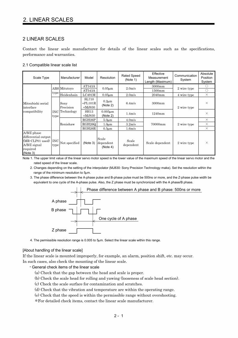
Contact the linear scale manufacturer for details of the linear scales such as the specifications,performance and warranties.
2.1 Compatible linear scale list
Scale Type Manufacturer Model Resolution Rated Speed(Note 1)
EffectiveMeasurement
Length (Maximum)
CommunicationSystem
AbsolutePositionSystem
AT343A 3000mmMitutoyo AT543A 0.05 m 2.0m/s 1500mm 2 wire typeABStype Heidenhain LC491M 0.05 m 2.0m/s 2040mm 4 wire type
SL710PL101RMJ830
0.2 m(Note 2) 6.4m/s 3000mmSony
PrecisionTechnology SH13
MJ8300.005 m(Note 2) 1.4m/s 1240mm
2 wire type
RGH26P 5.0 m 4.0m/sRGH26Q 1.0 m 3.2m/s
Mitsubishi serialinterfacecompatibility INC
type
RenishawRGH26R 0.5 m 1.6m/s
70000mm 2 wire type
A/B/Z phasedifferential output(MR-CLP01 used)A/B/Z signalrequired(Note 3)
INCtype Not specified (Note 3)
Scaledependent
(Note 4)
Scaledependent Scale dependent 2 wire type
Note 1. The upper limit value of the linear servo motor speed is the lower value of the maximum speed of the linear servo motor and therated speed of the linear scale.
2. Changes depending on the setting of the interpolator (MJ830: Sony Precision Technology make). Set the resolution within therange of the minimum resolution to 5 m.
3. The phase difference between the A-phase pulse and B-phase pulse must be 500ns or more, and the Z-phase pulse width beequivalent to one cycle of the A-phase pulse. Also, the Z phase must be synchronized with the A phase/B phase.
4. The permissible resolution range is 0.005 to 5 m. Select the linear scale within this range.
[About handling of the linear scale]If the linear scale is mounted improperly, for example, an alarm, position shift, etc. may occur.In such cases, also check the mounting of the linear scale.
General check items of the linear scale(a) Check that the gap between the head and scale is proper.(b) Check the scale head for rolling and yawing (looseness of scale head section).(c) Check the scale surface for contamination and scratches.(d) Check that the vibration and temperature are within the operating range.(e) Check that the speed is within the permissible range without overshooting.
For detailed check items, contact the linear scale manufacturer.
A phase
B phase
Phase difference between A phase and B phase: 500ns or more
Z phase
One cycle of A phase

2 - 2
2. LINEAR SCALES
2.1.1 Mitutoyo make linear scales (ABS type)
Specifications ReferenceContact Mitutoyo for the specifications of these linear scales.
Item SpecificationsModel AT343A- AT543A-System Capacitive, photoelectric, combined typeEffective measurement length 100 to 3000mm 100 to 1500mmResolution 0.05 m
Indication accuracy (20 )100 to 1500mm: 3 3L/1000 m
1600mm to 3000mm: 5 5L/1000 mL: Effective measurement length
100 to 1500mm: 3 3L/1000 mL: Effective measurement length
Supply power voltage 5V 5%Current consumption Max.250mA Max.270mARated response speed 2.0m/sMaximum response speed 2.0m/sOperating temperature range 0 to 45 (non-freezing) 0 to 50 (non-freezing)Operating humidity range 20 to 80%RH (non-condensing)Storage temperature range 20 to 70 (non-freezing)Storage humidity range 20 to 80%RH (non-condensing)
Dust tightness water tightness IP53 or equivalent(in the indication method given in the instruction manual of the Mitutoyo make linear scale)
Vibration resistance 100m/s2 (55 to 2000Hz) 150m/s2 (55 to 2000Hz)Shock resistance 150m/s2 (1/2sin, 11ms) 200m/s2 (1/2sin, 11ms)Sliding force 5N or lessOutput signal Serial communication compatibility
Output cable Mitutoyo make optionPart No. 09BAA598A to C:0.2, 2, 3m
Supplied as standardHead cable 5m output cable 1m
Connection cable(Mitsubishi option)
Refer to the standard connection example inChapter 3 and fabricate the cable.
When the MR-J2SCLCBL02M-P-H is used,any of the following Mitsubishi cables can alsobe used (Note 1).Output cable length 0.2m: MR-JCCBL2, 5,
10M-H2m: MR-JCCBL2, 5M-H3m: MR-JCCBL2M-H
Refer to the standard connection example inChapter 3 and fabricate the cable.
When the MR-J2SCLCBL02M-P-H is used,any of the following Mitsubishi cables can alsobe used (Note 1).MR-JCCBL2, 5, 10M-H
Note 1. The MR-JCCBL M-L and MR-JCCBL20M-H and more (20m and more) cannot be used.2. The battery (MR-BAT) is not required to configure an absolute position detection system.
Scale unit structure Reference
Home position
Decreasing direction
Mitutoyo AT343A
Output cable
Home position
Mitutoyo AT543A
Output cable Head cable
Increasing direction
Decreasing direction Increasing direction

2 - 3
2. LINEAR SCALES
AT343A and AT543A mounting dimension tables Reference (Dimension unit: mm)The following tables indicate L0 to L4 and number of mounting blocks or number of fixing holes in theoutline drawings shown on the next page.
MountingBlock Fixing
Pitch
MountingBlock Fixing
PitchModel
EffectiveMeasurement
LengthL0
MaximumMovingLength
L1
FullLength
L2L3 L4
Number ofMounting
Blocks(pcs.)
Model
EffectiveMeasurement
LengthL0
MaximumMovingLength
L1
FullLength
L2L3 L4
Number ofMounting
Blocks(pcs.)
AT343A-300
300 330 440 220 150 AT343A-1300
1300 1360 1470 735 325
AT343A-350
350 380 490 245 175AT343A-
14001400 1460 1570 785 350
AT343A-400
400 430 540 270 200AT343A-
15001500 1560 1670 835 375
AT343A-450
450 480 590 295 225AT343A-
16001600 1690 1800 900 400
AT343A-500 500 540 650 325 250
AT343A-1700 1700 1790 1900 950 425
AT343A-600 600 650 760 380 300
AT343A-1800 1800 1890 2000 1000 450
5
AT343A-700 700 760 870 435 350
AT343A-2000 2000 2100 2210 1105 335
AT343A-750 750 810 920 460 375
AT343A-2200 2200 2300 2410 1205 370
AT343A-800 800 860 970 485 400
AT343A-2400 2400 2500 2610 1305 400
7
AT343A-900 900 960 1070 535 450
AT343A-2500 2500 2600 2710 1355 315
AT343A-1000 1000 1060 1170 585 500
3
AT343A-2600 2600 2700 2810 1405 325
AT343A-1100 1100 1160 1270 635 275
AT343A-2800 2800 2900 3010 1505 350
AT343A-1200
1200 1260 1370 685 3005
AT343A-3000
3000 3050 3210 1605 375
9
Model
EffectiveMeasurement
LengthL0
MaximumMovingLength
L1
MountingHole Position
L2
FullLength
L3
Number ofFixingHoles
(n) (pcs.)
Model
EffectiveMeasurement
LengthL0
MaximumMovingLength
L1
MountingHole
PositionL2
FullLength
L3
Number ofFixingHoles
(n)(pcs.)
AT543A-100
100 120 12.5 225 3 AT543A-700
700 720 12.5 825 9
AT543A-150
150 170 37.5 275 3AT543A-
750750 770 37.5 875 9
AT543A-200
200 220 12.5 325 4AT543A-
800800 820 12.5 925 10
AT543A-250
250 270 37.5 375 4AT543A-
900900 920 12.5 1025 11
AT543A-300 300 320 12.5 425 5
AT543A-1000 1000 1020 12.5 1125 12
AT543A-350 350 370 37.5 475 5
AT543A-1100 1100 1120 12.5 1225 13
AT543A-400 400 420 12.5 525 6
AT543A-1200 1200 1220 12.5 1325 14
AT543A-450 450 470 37.5 575 6
AT543A-1300 1300 1320 12.5 1425 15
AT543A-500 500 520 12.5 625 7
AT543A-1400 1400 1420 12.5 1525 16
AT543A-600 600 620 12.5 725 8
AT543A-1500 1500 1520 12.5 1625 17

2 - 4
2. LINEAR SCALES
AT343A outline drawing Reference (Dimension unit: mm)Effective measurement length 300mm to 3000mmThis outline drawing is based on the data from Mitutoyo. Contact Mitutoyo for this outline drawing.
Spot
facin
gde
pth
5
7
711.6
A 32.523
X
36
29
50.5
15
95.5
0.1 A
2.5
7.5
807
15
0.2 G
(42)
812
.6
L
( 0.5
)
Scale body mountingsurface
Detection headmounting surface
Air supply port (M5)(Provided at both ends)
Full length L2
Mounting block fixing pitch L3
Mounting block fixing pitch L4 Mounting block fixing pitch L4
Elastically fixingarea
Mounting blockCompletelyfixing area
Elasticallyfixing area
Spot facingdepth 6.5 G: Machine guide
Effective measurement length L0Maximum moving length L1
View X
11 (h
exag
on)
Detection headmounting surface
Scale body mountingsurface
Option (L = any of three different lengths, 0.2m, 2m, 3m)
Signal cable(Vinyl sheathed) (
16)
1.5 0.2
66
0.3
60 0.2
60 0.290
2
8
The signal cable is optional.(Part No.09BAA598A to C: 0.2m, 2m, 3m)
1.5
0.2
0.2 G
AT543A outline drawing Reference (Dimension unit: mm)This outline drawing is based on the data from Mitutoyo. Contact Mitutoyo for this outline drawing.
Air supply port (M5 0.8)
A
0.1 G
8.5
3043
62(1
.5)
0.1G4
(17)40
4.5
804.5
(40)
( 19.
2)(1
9.6)
2013
.4 9284 0.1G
0.03/100
A R
Scale unit mounting surface
(Provided on both sides)
Mounting hole position: L2
(4.8)
Fixing screw: M4 0.8(L = 18mm or more)
Full length: L3 (4.8)
Mounting hole pitch P 100mm (n 1)
Position where absolute value data is zero(Nearly at scale center)
2 8 spot facingdepth 5(One side only)
2 M6 1(through)
60 0.2 Fixing screw: M4 0.8L = 20mm or more,or can be fixed with M6 screw from rear side.Effective measurement length: L0
Maximum moving length: L1 G: Machine guideFixing screw: M4 0.8L = 18mm or more,or can be fixed with M6 screw from rear side.
Output cable(Vinyl sheath)
Alarm display LED window
Waterproof connector
2 M6 1(through)
Scale unit
Head cable(Vinyl sheath)
Interface unit
Scale unit mounting surface
22
0.1A
1 0.1
n 5 (H
ole)45
.2
0.2
23
14
15.5
71 0.2
31
0.2 6.
5

2 - 5
2. LINEAR SCALES
Connection cable connection examples (1)The following cable wiring examples assume that the linear scale is connected directly to CN2 of the servoamplifier.
(1) Connection example of up to 5m wiring length (This connection example assumes that the followingoperating combination is satisfied.)
[Operating combination]
Used Wire Size Scale Model Scale Side Output Cable Specifications
AWG24 AT343A Mitutoyo make output cable 2mAWG24 AT543A Mitutoyo make output cable 1m
[Connection example]10120-3000PE, 10320-52F0-008(3M make or equivalent)
(Note 1)
Mitutoyo m
ake linear scale
19122011 717
1
P5LGP5LGMR
MRR
LG
616
Plate
MDMDR
SD
P5LGRQ/RQP5LG
FG(Note 2)
CN2 Servo motor
Encoder(Note 3)
Servo amplifierMR-J2S- B-PY096/S096
50m or less (2 wire type)
5m or less
Note 1. Do not connect the linear scale that is not indicated in this specification.2. Connect the shield wire to the plate (ground plate) in the connector securely.3. For the wiring to the servo motor, refer to the standard connection examples in Chapter 3 and the Instruction Manual of the MR-
J2S- B standard model.4. Contact the scale manufacturer for detailed specifications such as the combinations, models, types, etc. of the linear scale side
output cable and connector.
[Linear scale side connector] (Note 4)
ApplicableHousing
172161-9(Tyco Electronics
or equivalent)
RDAD-15S-LNA(Hirose Electricor equivalent)
RQ 1 7/RQ 2 8
P5 ( 5V) 7 3, 4LG (0V) 8 1, 2
FG 9 15

2 - 6
2. LINEAR SCALES
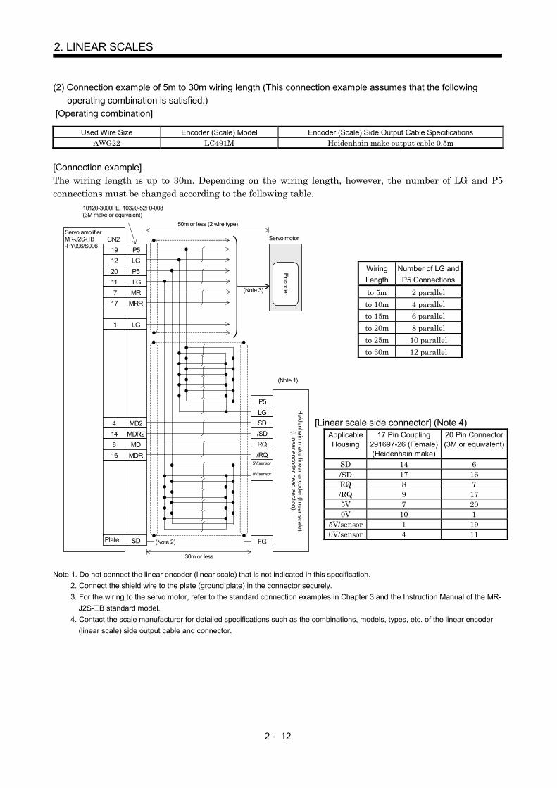
(2) Connection example of 5m to 30m wiring length (This connection example assumes that the followingoperating combination is satisfied.)
[Operating combination]
Used Wire Size Scale Model Scale Side Output Cable Specifications
AWG24 AT343A Mitutoyo make output cable 0.2mAWG22 AT543A Mitutoyo make output cable 1m
[Connection example]The wiring length is up to 30m. Depending on the wiring length, however, the number of LG and P5connections must be changed according to the following table.
(Note 1)
Mitutoyo m
ake linear scale19122011 717
1
P5LGP5LGMR
MRR
LG
616
Plate
MDMDR
SD
P5LGRQ/RQP5LG
FG(Note 2)
CN2 Servo motorE
ncoder(Note 3)
Servo amplifierMR-J2S- B-PY096/S096
10120-3000PE, 10320-52F0-008(3M make or equivalent)
50m or less (2 wire type)
30m or less
Note 1. Do not connect the linear scale that is not indicated in this specification.2. Connect the shield wire to the plate (ground plate) in the connector securely.3. For the wiring to the servo motor, refer to the standard connection examples in Chapter 3 and the Instruction Manual of the MR-
J2S- B standard model.4. Contact the scale manufacturer for detailed specifications such as the combinations, models, types, etc. of the linear scale side
output cable and connector.
WiringLength
Number of LG andP5 Connections
to 5m 2 parallelto 10m 4 parallelto 15m 6 parallelto 20m 8 parallelto 25m 10 parallelto 30m 12 parallel
[Linear scale side connector] (Note 4)
ApplicableHousing
172161-9(Tyco Electronics
or equivalent)
RDAD-15S-LNA(Hirose Electric or
equivalent)
RQ 1 7/RQ 2 8
P5 ( 5V) 7 3, 4LG (0V) 8 1, 2
FG 9 15

2 - 7
2. LINEAR SCALES
Connection cable connection examples (2)The following cable wiring examples assume that the linear scale is connected to CN2 of the servoamplifier using the option cable MR-J2SCLCBL02M-P-H.
(1) Connection example of up to 5m wiring length (This connection example assumes that the followingoperating combination is satisfied.)
[Operating combination]
Used Wire Size Scale Model Scale Side Output Cable Specifications
AWG24 AT343A Mitutoyo make output cable 2mAWG24 AT543A Mitutoyo make output cable 1m
[Connection example]
10120-3000PE, 10320-52F0-008(3M or equivalent)
To CN2
Servo motor
Encoder
(Note 1)
Mitutoyo m
ake linear scale
1912
P5LG
7172011
Plate
MRMRRP5LG
SD
P5LGRQ/RQP5LG
FG(Note 2)
(Note 3)
Servo amplifierMR-J2S- B-PY096/S096
Linearscaleconnector
Option cable(MR-J2SCLCBL02M-P-H)
5m or less
Note 1. Do not connect the linear scale that is not indicated in this specification.2. Connect the shield wire to the plate (ground plate) in the connector securely.3. For the wiring to the servo motor, refer to the standard connection examples in Chapter 3 and the Instruction Manual of the MR-
J2S- B standard model.4. Contact the scale manufacturer for detailed specifications such as the combinations, models, types, etc. of the linear scale side
output cable and connector.5. When the MR-J2SCLCBL02M-P-H is used, the Mitsubishi option cable can be used as the linear scale connection cable.
Scale ModelScale Side Output
Cable LengthMitsubishi Option Cable
Model
0.2m MR-JCCBL2, 5, 10M-H2m MR-JCCBL2, 5M-HAT343A3m MR-JCCBL2M-H
AT543A 1m MR-JCCBL2, 5, 10M-H
[Linear scale side connector] (Note 4)
ApplicableHousing
172161-9(Tyco Electronics
or equivalent)(Note 5)
RDAD-15S-LNA(Hirose Electric or
equivalent)
RQ 1 7/RQ 2 8
P5 ( 5V) 7 3, 4LG (0V) 8 1, 2
FG 9 15

2 - 8
2. LINEAR SCALES
(2) Connection example of 5m to 30m wiring length (This connection example assumes that the followingoperating combination is satisfied.)
[Operating combination]Used Wire Size Scale Model Scale Side Output Cable Specifications
AWG24 AT343A Mitutoyo make output cable 0.2mAWG22 AT543A Mitutoyo make output cable 1m
[Connection example]The wiring length is up to 30m. Depending on the wiring length, however, the number of LG and P5connections must be changed according to the following table.
10120-3000PE, 10320-52F0-008(3M or equivalent)
To CN2
Servo motor
Encoder
(Note 1)
Mitutoyo m
ake linear scale
1912
P5LG
7172011
Plate
MRMRRP5LG
SD
P5LGRQ/RQP5LG
FG(Note 2)
(Note 3)
Servo amplifierMR-J2S- B-PY096/S096
Linearscaleconnector
Option cable(MR-J2SCLCBL02M-P-H)
30m or less
Note 1. Do not connect the linear scale that is not indicated in this specification.2. Connect the shield wire to the plate (ground plate) in the connector securely.3. For the wiring to the servo motor, refer to the standard connection examples in Chapter 3 and the Instruction Manual of the MR-
J2S- B standard model.4. Contact the scale manufacturer for detailed specifications such as the combinations, models, types, etc. of the linear scale side
output cable and connector.5. When the MR-J2SCLCBL02M-P-H is used, the Mitsubishi option cable can be used as the linear scale connection cable.
Scale Model Scale Side Output Cable Length Mitsubishi Option Cable Model0.2m MR-JCCBL2, 5, 10M-H2m MR-JCCBL2, 5M-HAT343A3m MR-JCCBL2M-H
AT543A 1m MR-JCCBL2, 5, 10M-H
[Linear scale side connector] (Note 4)
ApplicableHousing
172161-9(Tyco Electronics
or equivalent)(Note 5)
RDAD-15S-LNA(Hirose Electric or
equivalent)
RQ 1 7/RQ 2 8
P5 ( 5V) 7 3, 4LG (0V) 8 1, 2
FG 9 15
WiringLength
Number of LGand P5
Connectionsto 5m 2 parallel
to 10m 4 parallelto 15m 6 parallelto 20m 8 parallelto 25m 10 parallelto 30m 12 parallel

2 - 9
2. LINEAR SCALES
2.1.2 Heidenhain make linear encoder (linear scale) (ABS type) Scheduled to be compatible
Specifications Reference Scheduled to be compatibleContact Heidenhain for the specifications of this linear encoder (linear scale).Heidenhain Sales Section No. 2: TEL. (03) 3234-7781
Item Specifications
Model LC491MSystem Photoelectric scanning systemEffective measurement length 70 to 2040mmResolution 0.05 m
Accuracy grade (20 )5 m
3 m (up to effective measurement length 1240)Supply power voltage 5V 5% on the linear encoder sideCurrent consumption Max.300mARated response speed 2.0m/sMaximum response speed 2.0m/sOperating temperature range 0 to 50 (non-freezing) (Note 2)Storage temperature range 20 to 70 (non-freezing)
Dust tightness water tightnessIP53 (when mounted according to the manual of the Heidenhain make linear encoder)
IP64 (when filled with compressed air)
Vibration resistance100m/s2 (DINIEC 68-2-6) without mounting spur
150m/s2 (DINIEC 68-2-6) with mounting spurShock resistance 150m/s2 (DINIEC 68-2-6) (11ms)Required feeding force 5N or lessOutput signal Serial communication compatibilityOutput cable 337 439 (17 pin coupling), 367 425 0 (20 pins), etc. (Note 1)Connection cable Refer to the standard connection example in Chapter 3 and fabricate the cable.Note 1. When the MR-J2SCLCBL02M-P-H is used, 367 425 (5m or less) can be connected directly.
2. The linear encoder (linear scale) is extremely sensitive to the operating temperature. When it exceeds 50 , an alarm mayoccur. It is recommended to pay special attention to the operating temperature and secure the temperature change margins.
3. The battery (MR-BAT) is not required to configure an absolute position detection system.
Linear encoder (linear scale) unit structure Reference Scheduled to be compatible
Decreasing direction Increasing direction(With the housing section fixed)
Home position

2 - 10
2. LINEAR SCALES
LC491M outline drawing Reference Scheduled to be compatible (Dimension unit: mm)This outline drawing is based on the data from Heidenhain. Contact Heidenhain for this outline drawing.
DIN ISO 8015ISO 2768-m H
2
Without mounting spurWith mounting spurMachine guideMeasurement point for adjustmentDimensional tolerance for machine installationCompressed air filling portMeasurement length starting point (pos. 20mm)
Mounting spur

2 - 11
2. LINEAR SCALES
Connection cable connection examples (1)The following cable wiring examples assume that the linear encoder (linear scale) is connected directly toCN2 of the servo amplifier.
CAUTION
When the Heidenhain linear encoder (linear scale) is used, thecommunication system is of 4 wire type.Change the setting of serial encoder cable selection (parameter No. 23) asindicated below. If a wrong value is set, a servo alarm (alarm 70) occurs.
Pr.23 2 (4 wire type setting is made valid.)
(1) Connection example of up to 5m wiring length (This connection example assumes that the followingoperating combination is satisfied.)
[Operating combination]
Used Wire Size Encoder (Scale) Model Encoder (Scale) Side Output Cable Specifications
AWG22 LC491M Heidenhain make output cable 0.5m
[Connection example]
(Note 1)
Heidenhain m
ake linear encoder(linear scale)
(Linear encoder head section)
19122011 717
1
P5LGP5LGMR
MRR
LG
414616
Plate
MD2MDR2MD
MDR
SD
P5LGSD/SDRQ/RQ
FG(Note 2)
CN2 Servo motor
Encoder(Note 3)
Servo amplifierMR-J2S- B-PY096/S096
5V/sensor
0V/sensor
10120-3000PE, 10320-52F0-008(3M make or equivalent)
50m or less (2 wire type)
5m or less
Note 1. Do not connect the linear encoder (linear scale) that is not indicated in this specification.2. Connect the shield wire to the plate (ground plate) in the connector securely.3. For the wiring to the servo motor, refer to the standard connection examples in Chapter 3 and the Instruction Manual of
the MR-J2S- B standard model.4. Contact the scale manufacturer for detailed specifications such as the combinations, models, types, etc. of the linear
encoder (linear scale) side output cable and connector.
[Linear scale side connector] (Note 4)
ApplicableHousing
17 Pin Coupling291697-26 (Female)(Heidenhain make)
20 Pin Connector(3M or equivalent)
SD 14 6/SD 17 16RQ 8 7/RQ 9 175V 7 200V 10 1
5V/sensor 1 190V/sensor 4 11
2 - 12
2. LINEAR SCALES
(2) Connection example of 5m to 30m wiring length (This connection example assumes that the followingoperating combination is satisfied.)
[Operating combination]
Used Wire Size Encoder (Scale) Model Encoder (Scale) Side Output Cable SpecificationsAWG22 LC491M Heidenhain make output cable 0.5m
[Connection example]The wiring length is up to 30m. Depending on the wiring length, however, the number of LG and P5connections must be changed according to the following table.
19122011 717
1
P5LGP5LGMR
MRR
LG
Plate SD (Note 2)
CN2 Servo motor
Encoder(Note 3)
Servo amplifierMR-J2S- B-PY096/S096
(Note 1)
Heidenhain m
ake linear encoder (linear scale)(Linear encoder head section)
P5LGSD/SDRQ/RQ
5V/sensor
0V/sensor
FG
414616
MD2MDR2
MDMDR
10120-3000PE, 10320-52F0-008(3M make or equivalent)
50m or less (2 wire type)
30m or less
Note 1. Do not connect the linear encoder (linear scale) that is not indicated in this specification.2. Connect the shield wire to the plate (ground plate) in the connector securely.3. For the wiring to the servo motor, refer to the standard connection examples in Chapter 3 and the Instruction Manual of the MR-
J2S- B standard model.4. Contact the scale manufacturer for detailed specifications such as the combinations, models, types, etc. of the linear encoder
(linear scale) side output cable and connector.
WiringLength
Number of LG andP5 Connections
to 5m 2 parallelto 10m 4 parallelto 15m 6 parallelto 20m 8 parallelto 25m 10 parallelto 30m 12 parallel
[Linear scale side connector] (Note 4)ApplicableHousing
17 Pin Coupling291697-26 (Female)(Heidenhain make)
20 Pin Connector(3M or equivalent)
SD 14 6/SD 17 16RQ 8 7/RQ 9 175V 7 200V 10 1
5V/sensor 1 190V/sensor 4 11

2 - 13
2. LINEAR SCALES
Connection cable connection examples (2)The following cable wiring examples assume that the linear encoder (linear scale) is connected to CN2 ofthe servo amplifier using the option cable MR-J2SCLCBL02M-P-H.
(1) Connection example of up to 5m wiring length (This connection example assumes that the followingoperating combination is satisfied.)
[Operating combination]
Used Wire Size Encoder (Scale) Model Encoder (Scale) Side Output Cable Specifications
AWG22 LC491M Heidenhain make output cable 0.5m
[Connection example]
10120-3000PE, 10320-52F0-52F0-008(3M or equivalent)
To CN2
Servo motor
Encoder
1912
P5LG
616
2011
Plate
MDMDR
P5LGSD (Note 2)
(Note 3)
Servo amplifierMR-J2S- B-PY096/S096
Linearscaleconnector
Option cable(MR-J2SCLCBL02M-P-H)
(Note 1)
Heidenhain m
ake linear encoder(linear scale)
(Linear encoder head section)
P5LGSD/SDRQ/RQ
FG
5V/sensor
0V/sensor
717
MRMRR
5m or less
Note 1. Do not connect the linear encoder (linear scale) that is not indicated in this specification.2. Connect the shield wire to the plate (ground plate) in the connector securely.3. For the wiring to the servo motor, refer to the standard connection examples in Chapter 3 and the Instruction Manual of the MR-
J2S- B standard model.4. Contact the scale manufacturer for detailed specifications such as the combinations, models, types, etc. of the linear encoder
(linear scale) side output cable and connector.5. Can be connected directly when the MR-J2SCLCBL02M-P-H is used.
[Linear scale side connector] (Note 4)
ApplicableHousing
17 Pin Coupling291697-26 (Female)(Heidenhain make)
20 Pin Connector(Note 5)
(3M or equivalent)
SD 14 6/SD 17 16RQ 8 7/RQ 9 175V 7 200V 10 1
5V/sensor 1 190V/sensor 4 11

2 - 14
2. LINEAR SCALES
(2) Connection example of 5m to 30m wiring length (This connection example assumes that the followingoperating combination is satisfied.)
[Operating combination]
Used Wire Size Encoder (Scale) Model Encoder (Scale) Side Output Cable Specifications
AWG22 LC491M Heidenhain make output cable 0.5m
[Connection example]The wiring length is up to 30m. Depending on the wiring length, however, the number of LG and P5connections must be changed according to the following table.
10120-3000PE, 10320-52F0-008(3M or equivalent)
To CN2
Servo motor
Encoder
1912
P5LG
616
2011
Plate
MDMDR
P5LG
SD(Note 2)
(Note 3)
Servo amplifierMR-J2S- B-PY096/S096
Linearscaleconnector
Option cable(MR-J2SCLCBL02M-P-H)
(Note 1)
Heidenhain m
ake linear encoder (linear scale)(Linear encoder head section)
P5LGSD/SDRQ/RQ
5V/sensor
0V/sensor
717
MRMRR
FG
30m or less
Note 1. Do not connect the linear encoder (linear scale) that is not indicated in this specification.2. Connect the shield wire to the plate (ground plate) in the connector securely.3. For the wiring to the servo motor, refer to the standard connection examples in Chapter 3 and the Instruction Manual of the MR-
J2S- B standard model.4. Contact the scale manufacturer for detailed specifications such as the combinations, models, types, etc. of the linear encoder
(linear scale) side output cable and connector.5. Can be connected directly when the MR-J2SCLCBL02M-P-H is used.
WiringLength
Number of LG andP5 Connections
to 5m 2 parallelto 10m 4 parallelto 15m 6 parallelto 20m 8 parallelto 25m 10 parallelto 30m 12 parallel
[Linear scale side connector] (Note 4)ApplicableHousing
17 Pin Coupling291697-26 (Female)(Heidenhain make)
20 Pin Connector(Note 5)
(3M or equivalent)SD 14 6/SD 17 16RQ 8 7/RQ 9 175V 7 200V 10 1
5V/sensor 1 190V/sensor 4 11

2 - 15
2. LINEAR SCALES
2.1.3 Renishaw make linear encoders (linear scales) (INC type)
Specifications ReferenceContact Renishaw for the specifications of these linear encoders (linear scales).Renishaw Encoder Section: TEL. (03) 5332-6023
Item Specifications
Model RGH26P RGH26Q RGH26RSystem Optical systemEffective measurement length Maximum length 70000mmResolution 5 m 1 m 0.5 mAccuracy (20 ) 3 m/m (when compensation is made between two points)Supply power voltage 5V 5%Current consumption Max.230mARated response speed (Note 1) 4.0m/s 3.2m/s 1.6m/sMaximum response speed 5.0m/s 4.0m/s 2.0m/sOperating temperature range 0 to 55 (non-freezing)Operating humidity range 10 to 90%RH (non-condensing)Storage temperature range 20 to 70 (non-freezing)Dust tightness water tightness IP50Vibration resistance 100m/s2 (55 to 2000HZ)Shock resistance 1000m/s2 (1/2sin, 11ms)
Output signalSerial communication compatibility
(Z phase data included, serial communication of reference mark data is also is made) (Note 3)Output cable Renishaw make N-15 PIN Dtype Dtype plug (0.5m)Connection cable Refer to the standard connection example in Chapter 3 and fabricate the cable.Note 1. Use at the rated speed or less.
2. A limit switch signal cannot be imported directly to the servo amplifier. When using a limit switch, use a photocoupler forisolation.
3. A home position return cannot be made if there is no encoder (scale) home position (reference mark). Always provide anencoder (scale) home position (reference mark).
Linear encoder (linear scale) unit structure Reference
RENISHAW RGH26
Increasing direction Decreasing direction
Note 1. Always set an encoder (scale) home position (reference mark).

2 - 16
2. LINEAR SCALES
RGH26P, RGH26Q, RGH26R outline drawing Reference (Dimension unit: mm)This outline drawing is based on the data from Renishaw. Contact Renishaw for this outline drawing.
Reference mark actuatorDynamic bending radius R50Static bending radius R10
6 minimumReference mark sensor position
Optical centerM3 0.5, two 9.5 deep holes
14(Yaw tolerance 0.5 )
0.38
MountingsurfaceSetupLED
(Roll tolerance 1.0 )0.13
Mounting surfacerange
Selectable mountingsurface
Q limit sensor position
M3 0.5, two 7.5deep holes
Mount the Qlimit switch withthe white point up.
P limit sensor position
P limit switchMount it with the white pointdirected toward the machinestock side.(Size is the same as that ofthe Q limit switch.)
The arrow indicates theforward moving directionof the read head relativeto the scale.
Scale mounting surface Clearance detail
(Pitch tolerance 1.0 )0.8
0.8 0.1
7.6
2713
9
3
11.61617
15.56
10.5
103
23.5
14.614.6
4438
10.652.2
4.7
7
14.5
22
4
2
3

2 - 17
2. LINEAR SCALES
Connection cable connection examples (1)The following cable wiring examples assume that the linear encoder (linear scale) is connected directly toCN2 of the servo amplifier.
(1) Connection example of up to 5m wiring length (This connection example assumes that the followingoperating combination is satisfied.)
[Operating combination]
Used Wire Size Encoder (Scale) Model Encoder (Scale) Side Output Cable Specifications
AWG22 RGH26 Renishaw make output cable 0.5m
[Connection example]
(Note 1)
Renishaw
make linear encoder
(linear scale)19122011 717
1
P5LGP5LGMR
MRR
LG
616
Plate
MDMDR
SD
P5LGMR
MRRP5LG
Inner
SD(Note 2)
CN2 Servo motorE
ncoder(Note 3)
Servo amplifierMR-J2S- B-PY096/S096
/P/Q
Limit switch output (Note 4)(Note 5)
10120-3000PE, 10320-52F0-008(3M make or equivalent)
50m or less (2 wire type)
5m or less
Note 1. Do not connect the linear encoder (linear scale) that is not indicated in this specification.2. Connect the shield wire to the plate (ground plate) in the connector securely.3. For the wiring to the servo motor, refer to the standard connection examples in Chapter 3 and the Instruction Manual of the MR-
J2S- B standard model.4. A limit switch signal cannot be imported directly to the servo amplifier. When using a limit switch, use a photocoupler for
isolation as shown above. Contact the scale manufacturer for detailed specifications of the limit switch.5. The encoder (scale) home position (reference mark) data is sent to the servo amplifier by serial communication.6. Contact the scale manufacturer for detailed specifications such as the combinations, models, types, etc. of the linear encoder
(linear scale) side output cable and connector.
/P, /Q
5V
0V
Renishaw make
linear encoder (linear scale)
Photocouplerisolation
[Linear encoder side connector] (Note 6)ApplicableHousing
D Sub 15 Pin FemaleEquivalent
Inner 15P5 7, 8LG 2, 9MR 10
MRR 1SD Case

2 - 18
2. LINEAR SCALES
(2) Connection example of 5m to 30m wiring length (This connection example assumes that the followingoperating combination is satisfied.)
[Operating combination]Used Wire Size Encoder (Scale) Model Encoder (Scale) Side Output Cable Specifications
AWG22 RGH26 Renishaw make output cable 0.5m [Connection example]The wiring length is up to 30m. Depending on the wiring length, however, the number of LG and P5connections must be changed according to the following table.
19122011 717
1
P5LGP5LGMR
MRR
LG
616
Plate
MDMDR
SD (Note 2)
CN2 Servo motor
Encoder(Note 3)
Servo amplifierMR-J2S- B-PY096/S096
(Note 1)
Renishaw
make linear encoder
(linear scale) (Note 5)
P5LGMR
MRRP5LG
Inner
SD
/P/Q
(Note 5)Limit switch output (Note 4)
10120-3000PE, 10320-52F0-008(3M make or equivalent)
50m or less (2 wire type)
30m or less
Note 1. Do not connect the linear encoder (linear scale) that is not indicated in this specification.2. Connect the shield wire to the plate (ground plate) in the connector securely.3. For the wiring to the servo motor, refer to the standard connection examples in Chapter 3 and the Instruction Manual of the MR-
J2S- B standard model.4. A limit switch signal cannot be imported directly to the servo amplifier. When using a limit switch, use a photocoupler for
isolation as shown above. Contact the scale manufacturer for detailed specifications of the limit switch.5. The encoder (scale) home position (reference mark) data is sent to the servo amplifier by serial communication.6. Contact the scale manufacturer for detailed specifications such as the combinations, models, types, etc. of the linear encoder
(linear scale) side output cable and connector.
WiringLength
Number of LG and P5Connections
to 5m 2 parallelto 10m 3 parallelto 15m 4 parallelto 20m 5 parallelto 25m 6 parallelto 30m 7 parallel
/P, /Q
5V
0V
Renishaw make
linear encoder (linear scale)
Photocoupler
isolation
[Linear encoder side connector] (Note 6)ApplicableHousing
D Sub 15 Pin FemaleEquivalent
Inner 15P5 7, 8LG 2, 9MR 10
MRR 1SD Case

2 - 19
2. LINEAR SCALES
Connection cable connection examples (2)The following cable wiring examples assume that the linear encoder (linear scale) is connected to CN2 ofthe servo amplifier using the option cable MR-J2SCLCBL02M-P-H.
(1) Connection example of up to 5m wiring length (This connection example assumes that the followingoperating combination is satisfied.)
[Operating combination]
Used Wire Size Encoder (Scale) Model Encoder (Scale) Side Output Cable Specifications
AWG22 RGH26 Renishaw make output cable 0.5m
[Connection example]
10120-3000PE, 10320-52F0-008(3M or equivalent)
To CN2
Servo motor
Encoder
1912
P5LG
7172011
Plate
MRMRRP5LG
SD (Note 2)
(Note 3)
Servo amplifierMR-J2S- B-PY096/S096
Linearscaleconnector
Option cable(MR-J2SCLCBL02M-P-H)
(Note 1)
Renishaw
make linear encoder
(linear scale)
P5LGMR
MRRP5LG
Inner
SD
/P/Q
(Note 5)Limit switch output (Note 4)
5m or less
Note 1. Do not connect the linear encoder (linear scale) that is not indicated in this specification.2. Connect the shield wire to the plate (ground plate) in the connector securely.3. For the wiring to the servo motor, refer to the standard connection examples in Chapter 3 and the Instruction Manual of the MR-
J2S- B standard model.4. A limit switch signal cannot be imported directly to the servo amplifier. When using a limit switch, use a photocoupler for
isolation as shown above. Contact the scale manufacturer for detailed specifications of the limit switch.5. The encoder (scale) home position (reference mark) data is sent to the servo amplifier by serial communication.6. Contact the scale manufacturer for detailed specifications such as the combinations, models, types, etc. of the linear encoder
(linear scale) side output cable and connector.
[Linear encoder side connector] (Note 6)ApplicableHousing
D Sub 15 Pin FemaleEquivalent
Inner 15P5 7, 8LG 2, 9MR 10
MRR 1SD Case
/P, /Q
5V
0V
Renishaw make
linear encoder (linear scale)
Photocoupler
isolation

2 - 20
2. LINEAR SCALES
(2) Connection example of 5m to 30m wiring length (This connection example assumes that the followingoperating combination is satisfied.)
[Operating combination]
Used Wire Size Encoder (Scale) Model Encoder (Scale) Side Output Cable SpecificationsAWG22 RGH26 Renishaw make output cable 0.5m
[Connection example]The wiring length is up to 30m. Depending on the wiring length, however, the number of LG and P5connections must be changed according to the following table.
10120-3000PE, 10320-52F0-008(3M or equivalent)
To CN2
Servo motor
Encoder
1912
P5LG
7172011
Plate
MRMRRP5LG
SD(Note 2)
(Note 3)
Servo amplifierMR-J2S- B-PY096/S096
Linearscaleconnector
Option cable(MR-J2SCLCBL02H-P-H)
(Note 1)
Renishaw
make linear encoder (linear scale)
P5LGMR
MRRP5LG
Inner
SD
/P/Q
(Note 5)Limit switch output (Note 4)
30m or less
Note 1. Do not connect the linear encoder (linear scale) that is not indicated in this specification.2. Connect the shield wire to the plate (ground plate) in the connector securely.3. For the wiring to the servo motor, refer to the standard connection examples in Chapter 3 and the Instruction Manual of the MR-
J2S- B standard model.4. A limit switch signal cannot be imported directly to the servo amplifier. When using a limit switch, use a photocoupler for
isolation as shown above. Contact the scale manufacturer for detailed specifications of the limit switch.5. The encoder (scale) home position (reference mark) data is sent to the servo amplifier by serial communication.6. Contact the scale manufacturer for detailed specifications such as the combinations, models, types, etc. of the linear encoder
(linear scale) side output cable and connector.
WiringLength
Number of LG andP5 Connections
to 5m 2 parallelto 10m 3 paralleltob15m 4 parallelto 20m 5 parallelto 25m 6 parallelto 30m 7 parallel
[Linear encoder side connector] (Note 6)ApplicableHousing
D Sub 15 Pin FemaleEquivalent
Inner 15P5 7, 8LG 2, 9MR 10
MRR 1SD Case
/P, /Q
5V
0V
Renishaw make
linear encoder (linear scale)
Photocoupler
isolation
2 - 21
2. LINEAR SCALES
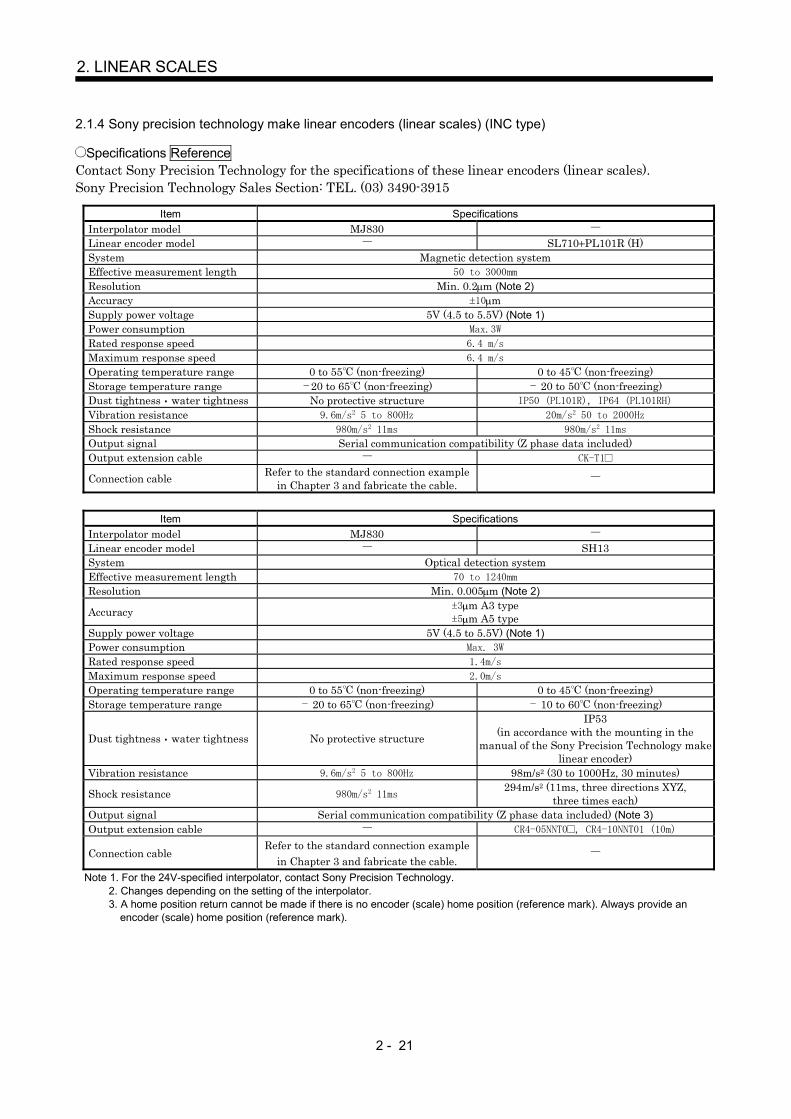
2.1.4 Sony precision technology make linear encoders (linear scales) (INC type)
Specifications ReferenceContact Sony Precision Technology for the specifications of these linear encoders (linear scales).Sony Precision Technology Sales Section: TEL. (03) 3490-3915
Item SpecificationsInterpolator model MJ830Linear encoder model SL710 PL101R (H)System Magnetic detection systemEffective measurement length 50 to 3000mm
Resolution Min. 0.2 m (Note 2)Accuracy 10 mSupply power voltage 5V (4.5 to 5.5V) (Note 1)Power consumption Max.3W
Rated response speed 6.4 m/s
Maximum response speed 6.4 m/s
Operating temperature range 0 to 55 (non-freezing) 0 to 45 (non-freezing)Storage temperature range 20 to 65 (non-freezing) 20 to 50 (non-freezing)Dust tightness water tightness No protective structure IP50 (PL101R), IP64 (PL101RH)
Vibration resistance 9.6m/s2 5 to 800Hz 20m/s2 50 to 2000Hz
Shock resistance 980m/s2 11ms 980m/s2 11ms
Output signal Serial communication compatibility (Z phase data included)Output extension cable CK-T1
Connection cable Refer to the standard connection examplein Chapter 3 and fabricate the cable.
Item SpecificationsInterpolator model MJ830Linear encoder model SH13System Optical detection systemEffective measurement length 70 to 1240mm
Resolution Min. 0.005 m (Note 2)
Accuracy 3 m A3 type5 m A5 type
Supply power voltage 5V (4.5 to 5.5V) (Note 1)Power consumption Max. 3W
Rated response speed 1.4m/s
Maximum response speed 2.0m/s
Operating temperature range 0 to 55 (non-freezing) 0 to 45 (non-freezing)Storage temperature range 20 to 65 (non-freezing) 10 to 60 (non-freezing)
Dust tightness water tightness No protective structure
IP53(in accordance with the mounting in the
manual of the Sony Precision Technology makelinear encoder)
Vibration resistance 9.6m/s2 5 to 800Hz 98m/s2 (30 to 1000Hz, 30 minutes)
Shock resistance 980m/s2 11ms294m/s2 (11ms, three directions XYZ,
three times each)Output signal Serial communication compatibility (Z phase data included) (Note 3)Output extension cable CR4-05NNT0 , CR4-10NNT01 (10m)
Connection cableRefer to the standard connection example
in Chapter 3 and fabricate the cable.Note 1. For the 24V-specified interpolator, contact Sony Precision Technology.
2. Changes depending on the setting of the interpolator.3. A home position return cannot be made if there is no encoder (scale) home position (reference mark). Always provide an
encoder (scale) home position (reference mark).
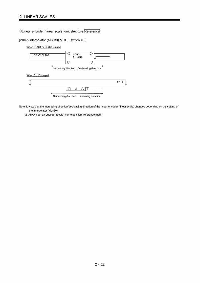
2 - 22
2. LINEAR SCALES
Linear encoder (linear scale) unit structure Reference
[When interpolator (MJ830) MODE switch = 5]
When PL101 or SL700 is used
SONY SL700 SONYPL101R
Increasing direction Decreasing direction
When SH13 is used
Decreasing direction Increasing direction
SH13
Note 1. Note that the increasing direction/decreasing direction of the linear encoder (linear scale) changes depending on the setting ofthe interpolator (MJ830).
2. Always set an encoder (scale) home position (reference mark).

2 - 23
2. LINEAR SCALES
SL710 outline drawing Reference (Dimension unit: mm)This outline drawing is based on the data from Sony Precision Technology. Contact Sony PrecisionTechnology for this outline drawing.
SL710
Mount the scale on a non-magnetic material.When mounting it on a magnetic material, providea non-magnetic layer of 3mm or more.
n - D reamed hole(For D parallel pin insertion)
P (n - 1 or 2)Effective measurement length (ML)
Full length = effective measurement length + 40(20)20
D/2
P 200
12
0.0
5
25
9
ML - P (n - 1) 200
PL101 outline drawing Reference (Dimension unit: mm)This outline drawing is based on the data from Sony Precision Technology. Contact Sony PrecisionTechnology for this outline drawing.
<PL101-RH (IP67 type)>
Offs
et
Effective measurement length (ML)Full length = effective measurement length + 40
Cle
aran
ce
2 2 - M3 depth 543.5
PitchRoll
Cable length: 3000mm48
Center mark
<PL101-N/PL101-R (IP50 type)>
Offs
et
Effective measurement length (ML)Full length = effective measurement length + 40
Cable length: 3000mm
RollPitch
Center mark43.52 2 - M3 depth 5
11.5 481.5
0.15
12 6 0.15
Cle
aran
ce12 6
20 20(20) (20)
25
912
0
.2
12
0.2
9
25
SH13 outline drawing Reference (Dimension unit: mm)This outline drawing is based on the data from Sony Precision Technology. Contact Sony PrecisionTechnology for this outline drawing.
SONY
SH13-
124 1240
2 450 434 620
114 1140
2 420 394 570
102 1020
2 380 354 510
092 920
1 507
460
082 820
1 457
410
077 770
1 432
385
072 720
1 407
360
067 670
1 382
335
062 620
1 357
310
057 570
1 332
285
052 520
1 307
260
047 470
235
042 420
210
037 370
185
032 320
160
027 270
135
022 220
110
017 170
85
012 120
60
007 70
35
L n
A P1 Z
mm
mm mm mm
Scale full length = L + 105Scale mounting hole pitch = L + 94
Middle support mountingposition = A
Middle support mountingposition = A
(n - 1) P1
Middle support AMiddle support BHome position mark
Head cable length = 1000(20)12 Scanning unit
212 56
8040 Z
4 84.
6
26.5
13
Home positionEffective measurement length = L
Left side measurement end Right side measurement endM4 (depth 10)3
3 374 M4 (depth 10)
123
6 4.5
20
2 - 5, 8.2 spot facingdepth 5
Air intake (M5)(5.5)Depth 5
Middle support B mounting side face
Middle support A mounting side face
2110.5
105
22
55
66
1915
2643
.5
7.5 13
2.5
0.
3
Effective measurement lengthMiddle support
Middle support mountinghole pitchHome position
5.5
3526
(25) 43.55
19
5.8

2 - 24
2. LINEAR SCALES
MJ830 outline drawing Reference (Dimension unit: mm)This outline drawing is based on the data from Sony Precision Technology. Contact Sony PrecisionTechnology for this outline drawing.
4.5 mounting hole
2613(13)3
4.5
9310
0(1
15)
138
124
1

2 - 25
2. LINEAR SCALES
Connection cable connection example (1)The following cable wiring example assumes that the linear encoder (linear scale) is connected directly toCN2 of the servo amplifier.
(1) Connection example of up to 30m wiring length (This connection example assumes that the followingoperating combination is satisfied.)
[Operating combination]
Used Wire Size Interpolator Model
AWG28 MJ830
[Connection example]
(Note 1)
Sony P
recisionTechnology m
akeinterpolator
19122011 717
1
P5LGP5LGMR
MRR
LG
616
Plate
MDMDRSD
LGLGMR
MRRSHD(Note 2)
CN2 Servo motor
Encoder
(Note 3)
Servo amplifierMR-J2S- B-PY096/S096
Sony P
recision Technology make
linear encoder (linear scale)Stabilizedpower supply
(5V)
10120-3000PE, 10320-52F0-008(3M make or equivalent)
50m or less (2 wire type)
30m or less
Note 1. Do not connect the linear encoder (linear scale) that is not indicated in this specification.2. Connect the shield wire to the plate (ground plate) in the connector securely.3. For the wiring to the servo motor, refer to the standard connection examples in Chapter 3 and the Instruction Manual of the MR-
J2S- B standard model.4. Contact the scale manufacturer for detailed specifications such as the combinations, models, types, etc. of the linear encoder
(linear scale) side output cable and connector.
[Linear encoder side connector] (Note 4)ApplicableHousing
10114-3000PE, 10314-52F0-0083M or Equivalent
OV 11, 12MR 4
MRR 5SHD 7

2 - 26
2. LINEAR SCALES
Connection cable connection example (2)The following cable wiring example assumes that the linear encoder (linear scale) is connected to CN2 ofthe servo amplifier using the option cable MR-J2SCLCBL02M-P-H.
(1) Connection example of up to 30m wiring length (This connection example assumes that the followingoperating combination is satisfied.)
[Operating combination]
Used Wire Size Interpolator Model
AWG28 MJ830
[Connection example]
10120-3000PE, 10320-52F0-008(3M make or equivalent)
To CN2
Servo motor
Encoder
1211
LGLG
717
Plate
MRMRRSD (Note 2)
(Note 3)
Servo amplifierMR-J2S- B-PY096/S096
Linearscaleconnector
Option cable(MR-J2SCLCBL02M-P-H)
(Note 1)
Sony P
recisionTechnology m
akeinterpolator
LGLGMR
MRRSHD
Sony P
recision Technology make
linear encoder (linear scale)Stabilizedpower supply
(5V)
30m or less
Note 1. Do not connect the linear encoder (linear scale) that is not indicated in this specification.2. Connect the shield wire to the plate (ground plate) in the connector securely.3. For the wiring to the servo motor, refer to the standard connection examples in Chapter 3 and the Instruction Manual of the MR-
J2S- B standard model.4. Contact the scale manufacturer for detailed specifications such as the combinations, models, types, etc. of the linear encoder
(linear scale) side output cable and connector.
[Linear encoder side connector] (Note 4)ApplicableHousing
10114-3000PE, 10314-52F0-0083M or Equivalent
OV 11, 12MR 4
MRR 5SHD 7

2 - 27
2. LINEAR SCALES
2.2 A B Z-phase differential input interface unit specifications
Contact the linear scale manufacturer for the specifications of the A/B/Z-phase differential output linearscale. (Since the permissible resolution range is 0.005 to 5 m, select the linear scale within this range.)
Specifications
Item Description
Model MR-J2S-CLP01Permissiblevoltagefluctuation
DC4.85 to 5.25VPowersupply
Currentconsumption
200mA (when power is supplied from servo amplifier)250mA (when power is supplied from external power supply) (Note 1)
Input signal A B Z-phase differential input signalMinimum phasedifference
500ns
Output signal High-speed serial communication (Z phase data included)Structure Open (IP00)
Ambienttemperature
0 to 55 (non-freezing)
Storagetemperature
20 to 65 (non-freezing)
Ambienthumidity
90%RH or less (non-condensing)
Storagehumidity
90%RH or less (non-condensing)
AmbienceIndoors (no direct sunlight)
Without corrosive gas, flammable gas, oil mist, dust and dirtAltitude 1000m or less above sea level
Env
iron
men
t
Vibration 5.9m/s2 or lessWeight 0.4kg
Note 1. The power supply of the linear scale is not included. When an external power supply is used, an up to 350mA linearscale can be used.

2 - 28
2. LINEAR SCALES
MR-J2S-CLP01 outline drawing[Unit: mm]
6 hole
Terminal layout
Model Weight [kg]
(75) 90
1.6
615
6
168
R3
TE1 P5LP50
MR-J2S-CLP01 0.4
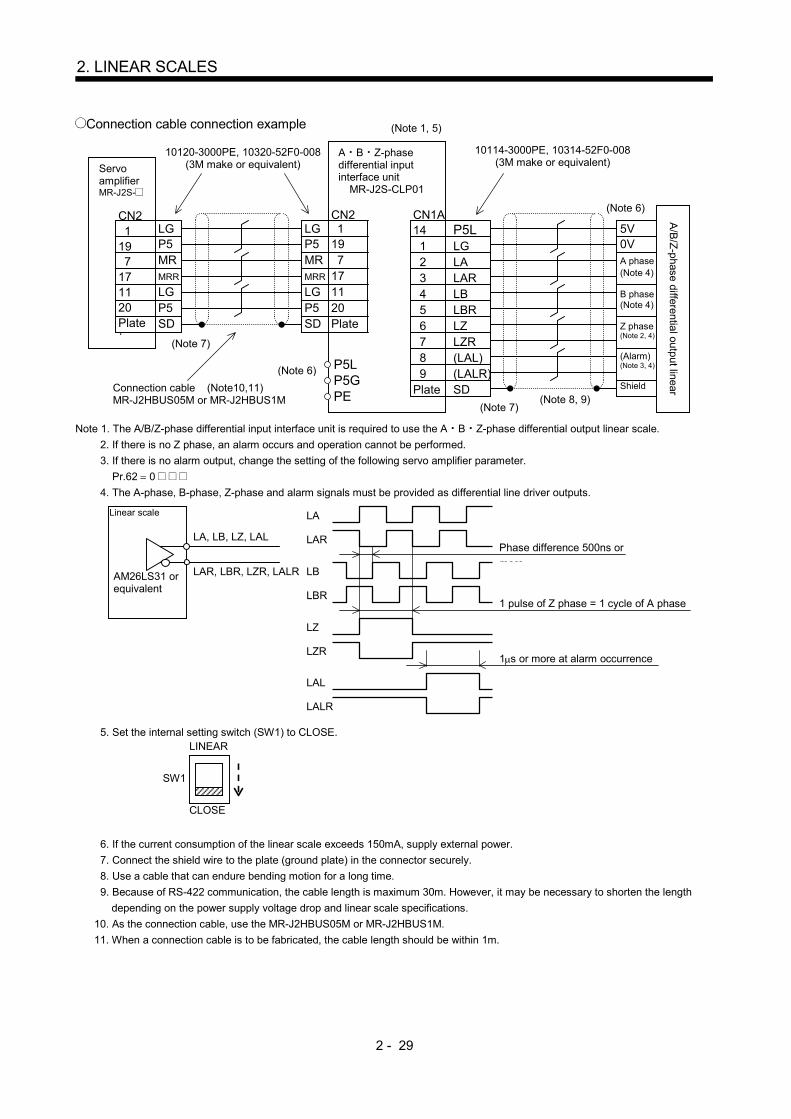
2 - 29
2. LINEAR SCALES
Connection cable connection example
Note 1. The A/B/Z-phase differential input interface unit is required to use the A B Z-phase differential output linear scale.2. If there is no Z phase, an alarm occurs and operation cannot be performed.3. If there is no alarm output, change the setting of the following servo amplifier parameter. Pr.62 0 4. The A-phase, B-phase, Z-phase and alarm signals must be provided as differential line driver outputs.
5. Set the internal setting switch (SW1) to CLOSE.
6. If the current consumption of the linear scale exceeds 150mA, supply external power.7. Connect the shield wire to the plate (ground plate) in the connector securely.8. Use a cable that can endure bending motion for a long time.9. Because of RS-422 communication, the cable length is maximum 30m. However, it may be necessary to shorten the length
depending on the power supply voltage drop and linear scale specifications.10. As the connection cable, use the MR-J2HBUS05M or MR-J2HBUS1M.11. When a connection cable is to be fabricated, the cable length should be within 1m.
A B Z-phasedifferential inputinterface unit
MR-J2S-CLP01
(Note 7)
ServoamplifierMR-J2S-
CN21
197
171120Plateト
LGP5MRMRR
LGP5SD
LGP5MRMRR
LGP5SD
CN21
197
171120Plate
10120-3000PE, 10320-52F0-008(3M make or equivalent)
A/B
/Z-phase differential output linearConnection cable (Note10,11)MR-J2HBUS05M or MR-J2HBUS1M
10114-3000PE, 10314-52F0-008(3M make or equivalent)
P5LLGLALARLBLBRLZLZR(LAL)(LALR)SD
CN1A14123456789
Plate
5V0VA phase(Note 4)
B phase(Note 4)
Z phase(Note 2, 4)
(Alarm)(Note 3, 4)
Shield
(Note 7)
(Note 1, 5)
(Note 6)
(Note 8, 9)
P5LP5GPE
(Note 6)
LA, LB, LZ, LAL
LAR, LBR, LZR, LALRAM26LS31 orequivalent
Linear scale
LALR
LAL
LZR
LZ
LBR
LB
LAR
LA
Phase difference 500ns ormore
1 pulse of Z phase = 1 cycle of A phase
1 s or more at alarm occurrence
LINEAR
CLOSE
SW1

2 - 30
2. LINEAR SCALES
MEMO

3 - 1
3. SIGNALS AND WIRING
3 SIGNALS AND WIRING3.1 Standard connection examples of full closed control servo amplifier control signals
(1) When MR-J2S-CLP01 is used
24VDC
Note1. Use the MR-J2HBUS M-A or MR-J2HBUS M cable within the overall length of 30m. To improve noise immunity, it is recommended to use a cable clamp and data line filters (connect 3 or 4 pcs. in series) near the connector lead-out area.2. The motor side connections of the second axis and later are omitted.3. Up to eight axes (n = 0 to 7) can be connected. The MR-H BN type servo can also be connected to the same bus. (Note that the cable differs.)4. In this example, the motor is equipped with an electromagnetic brake. The power supply connected to the electromagnetic brake is irrelevant to the polarity. The HC-SFS121 to 301, 202 to 702, 203, 353 and HC-UFS202 to 502 use different connectors.5. Connect the shield wire to the plate (ground plate) in the connector securely.6. Connect the diode in the correct orientation. If it is connected oppositely, the amplifier will fail and signals will not be output.7. A forced stop of the corresponding axis servo amplifier alone. Use it as necessary when the QD75M, Q172, Q173 or Position Board is connected. Do not use it when any of the A171SH, A172SH, A173UH and A273UH is connected. When this signal is not used, short EM1-SG within the connector. Make an emergency stop of the whole system on the controller side. A forced stop input can be made invalid using parameter No. 23.8. For details, refer to the "MR-J2S-B Instruction Manual" and "MR-J2S-CLP01 Installation Guide".9. Always use a shielded multi-core cable. Up to 15m is allowed in noise- free environment. However, the cable length should be within 3m when 38,400bps or more baud rate is set for RS-232C communication.10. When using an external power supply, do not connect VDD-COM.11. When the personal computer is connected simultaneously with analog monitor output 1 (MO1) or analog monitor output 2 (MO2), use the maintenance relay card (MR-J2CN3TM).12. CN1A, CN1B, CN2 and CN3 have the same shape. Incorrect connection of the connector can cause a failure.13. In the case of single-phase 100VAC (MR-J2S-40B1-PY096 or less) or single-phase 230VAC (MR-J2S-70B-PY096 or less), connect the power supply to the L1, L2 terminals and keep L3 open.
GH
76
8 9
54
14
23
LZLZRLAL
LALR
SD
LBRLB
P5L
LARLA
CN1A
CLOSE
CN1B
1 LG
7 8 1 2 4 5
9
P5LG
MRMRR MD
MDR
SD 3 BAT
6 CNT
B1
B2
Z
SRCDABFGNM
24VDC
ABCD
EM1
L1
L2
L3
C
P
N
TE1
L11
L21
B1
B25
6
Z RA1
1
2
3
4L11
L21
L1
L2
L3
TE1
TE2P
C
D
CN312
21
11Rx
LG
LGTx RD
SDGND
GND
RS-232C
CS1
0
MO1LG
MO2LG
4 11411
EMG 20 EM13 SG
RA1 13 MBR5 COM
10 VDD
SD
LA616 LAR7 LB
LBR17LZ8LZR18
CS1
1
8 1 2 4 5
9
P5LGMR
MRR MDMDR
SD 3 BAT
6 CNT
76
8 9
54
14
23
LZLZRLALLALR
SD
LBRLB
P5L
LARLA
CN1A1 LG
MR-J2S-CLP01
7
RA1
CN1BCS1
Configure a sequence that will turn offMC at an alarm or emergency stop.
MCNFBPower supplyThree-phase 200 to230VAC or single-phase100VAC/single-phase230VAC (Note 13)
If the regenerative option isconnected incorrectly, the servoamplifier is damaged.
In the case of MR-J2S-500B/700BConfigure a sequence that willturn off MC at an alarm oremergency stop.
Servo amplifierMR-J2S- B-S096
Regenerativeoption
When connecting an externalregenerative option, alwaysdisconnect the link from across C-P.
Regenerativeoption
When connecting an externalregenerative option, always disconnect the link from across P-D.
ControllerA171SHA172SHA173UHA273UHQD75MQ172Q173Position Board
Cableclamp
Use the MR-J2HBUS M-A cable with theA171SH,A172SH, A173UH or A273UH, andthe MR-J2HBUS M cable with the QD75M. (Note 1)Refer to the "Motion Controller Q Series Catalog"for the cable between Q172/Q173 and amplifier,and to the "Position Board, Interface Board NewProduct News (SV0206-1)" for the cable betweenPosition Board and amplifier.
MR-J2HBUS M cable
MR-J2HBUS M cable
Always insert the terminatingconnector (MR-A-TM) to thetermination of the servo bus.
Servo amplifierMR-J2S- B
-PY096/-S096(Axis 1)
(Note 12)
CN
2
CN
1A (Note 12)
Plate
CN
1B (Note 12)
Servo amplifierMR-J2S- B
(-PY096/-S096)(Axis 2)
CN
1A
(Note 12)
CN
1B (Note 2)
(Note 2)
CN
1A
(Note 12)
CN
1B
Servo amplifierMR-J2S- B
(-PY096/-S096)(Axis n)
Set SW1 toCLOSE.
(Note 3)
CN
2
(Note 12)MR-J2HBUS McableUse 1m or less.
A B Z-phase differentialinput interface unitMR-J2S-CLP01
Plate
(Note 12)(Note 12)
Shut off when servo-onsignal turns off or alarmsignal turns on.
MotorHC-KFS, MFS,UFS3000r/min series
(Note 4)
SM
Electromagneticbrake
Enco
der
General-purposelinear scale orrotary encoder
(A B Z-phasedifferential outputtype)
Connect the MR-HP4CN1connector to the CN1Aconnector.
(Note 8)
MR-JCCBL M-H cable orMR-JCCBL M-L cableUse 30m or less.
15m or less(Note 9)
Commercially availablepersonal computer
Windows
(Note 7)Forced stop
10m or less
(Note 6)Electromagneticbrake interlock
(Note 10) When not using the external power supply, always connect VDD-COM.
Max. +1mA meterZero-center ( 10V output)
A
A
Monitor output 1(Note 11)
Monitor output 2
10k
10k
Encoder A-phase pulse(Differential line driver)
Encoder B-phase pulse(Differential line driver)
Encoder Z-phase pulse(Differential line driver)
2m or less
Plate
(Note 12)
Shut off when servo-onsignal turns off or alarmsignal turns on.
MotorHC-SFS, RFS,UFS2000r/min series
SM
(Note 4)Electromagneticbrake
Enco
der
General-purposelinear scale orrotary encoder
(A/B/Z-phasedifferential outputtype)
Connect the MR-HP4CN1connector to the CN1Aconnector.
MR-JHSCBL M-H cable,MR-JHSCBL M -L cableor MR-ENCBL M-H cableUse 30m or less.
(Note 8)
U
V
W
AEM1
n - 1
UVW
UVW
MR-J2S- B-PY096/-S096
NFB MC
U
V
W
D
D

3 - 2
3. SIGNALS AND WIRING
(2) When serial communication compatible linear scale is connected to closed end F/B
P5CN2
LGP5LG
MRMRR
19
MRR
10
MR
SD
17
P5
711
12 20
1 P5
LG
P5
LG
LG18
P5
2 LGLG
MD2MDR2
MDMDR
BAT
616
9
414
SD
SD19
MRR
18
MR 17
P5
7
2
12
1
20
LG
P5
LG
P5
LG
11 LG
MD6MDR16
BAT9
SRCDABFGNM
19
MRR
10
MR
SD
17
P5
711
12 20
1 P5
LG
P5
LG
LG18
P5
2 LG
19
MRR MR
SD
17
P5
711
12 20
1 P5
LG
LG
LG18
P5
2 LG
CN1 A
CN1 B
CN3
7 8 1 2 4 5
9
P5LGMRMRR MD
MDR
SD 3 BAT
6 CNT
8 1 2 4 5
9
P5LGMR
MRR MDMDR
SD 3 BAT
6 CNT
717
19122011
1
7 19
MRR MR
SD
17
P5
711
12 20
1 P5
LG
LG
LG18
P5
2 LG
201117
197
P5SD
LGMRRMRP5
12 LG
17
127
SDMRRMRLG
11 LG
SHDMRRMR0V0V
P5FG
LG/ RQRQP5LG
20
1117
197
P5SD
LGMRRMRP5
12 LG
P5/ P
LGMRRMRP5LG
/ Q
17
716
196
MRR
SD
MRMDRMDP5
12 LG
/ RQRQ/ SDSD5V0V
FG
11 LG20 P5
CN25m
30m
5m
CaseSD
For connection of TE1, TE2and connectors CN1A,CN1B, CN3, refer to "3.1(1) When MR-J2S-CLP01 isused".
Using the ABS type scaleenables an absolute positiondetection system to beconfigured. At that time,the battery (MR-BAT) is notneeded.
Servo amplifierMR-J2S- B-PY096/-S096
Plate
Plate
Motor connector
MR-JCCBL M-H cable orMR-JCCBL M-L cableUse 30m or less.
Motor connector
MotorHC-KFS, MFS,UFS3000r/min series
Enco
der
Enco
der
Plate
MR-JHSCBL M -H cable,MR-JHSCBL M -L cable orMR-ENCBL M-H cableUse 30m or less.
MotorHC-SFS, RFS,UFS2000r/min series
Linear scaleconnector
Plate
(Note1) (Note2)
(Note6)
(Note6)
(Note7)
(Note7)
(Note3)
(Note7)
(Note4, 7)
5m(Note6)
Mitu
toyo
mak
elin
ear s
cale
Sony
Pre
cisi
on T
echn
olog
ym
ake
inte
rpol
ator
Son
y P
reci
sion
Tec
hnol
ogy
mak
e lin
ear e
ncod
er (l
inea
r sca
le)
Stabilizedpowersupply(5V)
Ren
isha
w m
ake
linea
r enc
oder
(line
ar s
cale
)H
eide
nhai
n m
ake
linea
ren
code
r (lin
ear s
cale
)
Limit switch output
0V/sensor5V/sensor
The Heidenhain make linear scale is compatiblewith the MR-J2S-B-PY096/-S096 type only.
The option cable (MR-J2SCLCBL02M-P-H) can be used forconnection between CN2 and motor connector or betweenCN2 and linear scale connector.
For CN2
Amplifier connector(3M or equivalent)10120-3000PE (connector)10320-52F0-008 (shell kit)
(Note 5)For motor
Motor connector (3M or equivalent)10220-0200EL (connector)10320-E2W0-008 (shell kit)
Linear scale connector (3M or equivalent)10220-0200EL (connector)10320-E2W0-008 (shell kit)
(Note 5)For linear scale
mot
or S
CAL
E
Note 1. Fabricate the linear scale connection cable on the customer side using the optional CN1 connector (MR-J2CN1). 2. Contact the corresponding scale manufacturer for the linear scale and interpolator side pin numbers. 3. For the specifications of the stabilized power supply, contact Sony Precision Technology. 4. To use the Heidenhain make linear scale, the parameter No. 23 (in the case of the MR-J2S-B-PY096/-S096 type) setting must be changed. Refer to "CHAPTER 2 LINEAR SCALES" for more information. 5. The motor connector and linear scale connector have the same shape. Incorrect connection of the connector can cause a failure. 6. This wiring is for AWG22. Up to 30m is allowed by changing the wiring. Refer to " CHAPTER 2 LINEAR SCALES " for details of wiring. 7. Use after confirming the specifications of the linear scale such as the temperatures, vibration resistance and protective structure. For use in the environment having much static noise, contact the scale manufacturer separately.
Plate
Plate
Plate
Plate
(Note1) (Note2)
(Note2)(Note1)
(Note2)(Note1)
inner
0.2m
Plate
Plate

3 - 3
3. SIGNALS AND WIRING
(3) When serial communication compatible servo motor is connected to closed end F/B
P5CN2
LGP5LGMRMRR
19
MRR
10
MR
SD
17
P5
711
12 20
1 P5
LG
P5
LG
LG18
P5
2 LGLG
MD2MDR2
MDMDR
BAT
616
9
414
SD
19
MRR
18
MR 17
P5
7
2
12
1
20
LG
P5
LG
P5
LG
11 LG
MD6MDR16
BAT9SD
SD
19
MRR
18
MR 17
P5
7
2
12
1
20
LG
P5
LG
P5
LG
11 LG
MD6MDR16
BAT9
7 8 1 2 4 5
9
P5LGMR
MRR MDMDR
SD 3 BAT
6 CNT
8 1 2 4 5
9
P5LGMR
MRR MD
MDR
SD 3 BAT
6 CNT
7
SRCDABFGNM
19
MRR
10
MR
SD
17
P5
711
12 20
1 P5
LG
P5
LG
LG18
P5
2 LG
19
MRR MR
SD
17
P5
711
12 20
1 P5
LG
LG
LG18
P5
2 LG
CN1 A
CN1 B
CN3
7 8 1 2 4 5
9
P5LGMR
MRR MD
MDR
SD 3 BAT
6 CNT
8 1 2 4 5
9
P5LGMR
MRR MDMDR
SD 3 BAT
6 CNT
7
717
19122011
1
19
MRR MR
SD
17
P5
711
12 20
1 P5
LG
LG
LG18
P5
2 LG
CN2
For connection of TE1, TE2and connectors CN1A,CN1B, CN3, refer to "3.1(1) When MR-J2S-CLP01 isused".
Servo amplifierMR-J2S- B
-PY096/-S096
Plate Plate
Motor connector
MR-JCCBL M-H cable orMR-JCCBL M-L cableUse 30m or less.
Plate Plate
Motor connector
MR-JHSCBL M -H cable,MR-JHSCBL M -L cable orMR-ENCBL M-H cableUse 30m or less.
Drive motorHC-KFS, MFS,UFS3000r/min series
Drive motorHC-SFS, RFS,UFS2000r/min series
Enco
der
Enco
der
Position detectionmotorHC-KFS, MFS series
Enco
der
Position detector connector
MR-JCCBL M-H cable orMR-JCCBL M-L cableUse 30m or less.
PlatePlate
Plate(Note1) (Note1)
The option cable (MR-J2SCLCBL02M-P-H) can be used forconnection between CN2 and motor connector or betweenCN2 and linear scale connector.
For CN2
Amplifier connector(3M or equivalent)10120-3000VE (connector)10320-52F0-008 (shell kit)
(Note 2)For motor
Motor connector (3M or equivalent)10220-0200EL (connector)10320-E2W0-008 (shell kit)
Linear scale connector (3M or equivalent)10220-0200EL (connector)10320-E2W0-008 (shell kit)
(Note 2)For position detector
mot
or S
CA
LE
Note 1. Fabricate the linear scale connection cable on the customer side using the optional CN1 connector (MR-J2CWired in the option cable (MR-J2SCLCBL02M-P-H). Note that it is not compatible with an absolute position detection system. 2. The motor connector and position detector connector have the same shape. Incorrect connection of the connector can cause a failure.
0.2m

3 - 4
3. SIGNALS AND WIRING
(4) About CN2 wiring for closed end serial communication compatibility (when MR-J2CLCBL02M-P-H is used)For use of the serial I/F compatible encoder, the wiring diagram shows that a bifurcated cable is to beconnected. When using the option cable MR-J2CLCBL02M-P-H in the bifurcated wiring area, performwiring as shown below.
(a) For serial communication compatible linear scale
Servo amplifier
CN2
Encoder signalLinear scale
3) Serial communication signal cable
Servo motor
1) MR-J2SCLCBL02M-P-H
2)
1) Use the MR-J2SCLCBL02M-P-H.(Refer to "CHAPTER 7 OPTIONS AND AUXILIARY EQUIPMENT" for details such as internalconnection.)
2) Use the encoder cable (e.g. MR-JCCBL M-H, MR-JHSCBL M-H, MR-ENCBL M-H) of theservo motor.
3) The wiring method changes depending on the linear scale.Confirm "CHAPTER 2 LINEAR SCALES" and fabricate a connection cable on the customer side.
(b) For serial communication compatible rotary encoder
Servo amplifier
CN2
Encoder signalClosed end servo motorfor detection
2) Encoder signal
Drive servo motor
1) MR-J2SCLCBL02M-P-H
2) (Note 2)
1) Use the MR-J2SCLCBL02M-P-H.(Refer to " CHAPTER 7 OPTIONS AND AUXILIARY EQUIPMENT " for details such asinternal connection.)
2) Use the encoder cable (e.g. MR-JCCBL M-H, MR-JHSCBL M-H, MR-ENCBL M-H) of theservo motor.

3 - 5
3. SIGNALS AND WIRING
3.2 Signal terminal explanation
(1) Main circuit terminal block, control circuit terminal block
Signal Name Abbreviation Terminal Block
Description
Main circuitpower supply L1, L2, L3 TE1
Main circuit power input terminals.MR-J2S- B : Connect three-phase 200 to 230VAC/50, 60Hz.MR-J2S- B1 : Connect single-phase 100 to 120VAC/50, 60Hz.
Servo motoroutput U, V, W TE1
Servo motor power output terminals.Connect to the servo motor power supply terminals (U, V, W). Duringpower-on, do not open or close the motor power line. Otherwise, amalfunction or faulty may occur.
Controlcircuit power
supplyL11, L21 TE2
Control circuit power input terminals.L11 should be in the same power supply phase with L1, and L21 with L2.MR-J2S- B : Connect to single-phase 200 to 230VAC/50, 60Hz.MR-J2S- B1 : Connect to single-phase 100 to 120VAC/50, 60Hz.
Regenerativeoption P, C, D TE2
Regenerative option connection terminals.Factory-wired across P-D.When using the regenerative option, always remove the wire across P-Dand connect the regenerative option across P-C.
N Keep open.
Protectiveearth PE Chassis
Ground terminal.Connect to the earth terminal of the servo motor and the protective earth ofthe control box for grounding.
(2) CN3
Signal Name Abbreviation Pin No. Function/Application
Digital I/F powersupply input COM 5
24VDC for input interface is input.Digital interface driver power input terminal.COM is all connected internally.When using an external power supply, connect a power supply of 24VDCand 200mA or more instead of VDD.
I/F internalpower supply
outputVDD 10
Digital interface driver power output terminal.24VDC is output across VDD-SG. Connect with COM.(Do not make connection when using an external power supply.)The permissible current is 80mA.
Digital I/Fcommon SG 3
24V common for VDD/COM and isolated from LG.
Control common LG 1, 11 Control common used as a monitor common.LA 6Encoder
A-phase pulse LAR 16
Encoder A-phase pulse output terminals.The pulses set in parameter No. 38 (ENR) in the output type selected inparameter No. 68 (FC2) are output in the differential line driver system.
LB 7EncoderB-phase pulse LBR 17
Encoder B-phase pulse output terminals.The pulses set in parameter No. 38 (ENR) in the output type selected inparameter No. 68 (FC2) are output in the differential line driver system.
LZ 8Encoder
Z-phase pulse LZR 18
Encoder Z-phase pulse output terminals.1 pulse is output per servo motor revolution.By setting parameter No. 68 (FC2), the Z phase (reference mark) of the fullclosed encoder can be output.
MO1 4
Monitor outputMO2 14
Monitor output signal output terminals.The data set in parameter No. 22 (MOD) is output in analog form.The multiplying factor can be set in parameter No. 22 (MOD).
Electromagneticbrake interlock MBR 13
MBR-SG are disconnected at servo-off or alarm. At alarm occurrence, theyare disconnected independently of the base circuit state.
Forced stop EM1 20When EM1-SG are opened, a forced stop state occurs, the servo switchesoff, and the dynamic brake is operated to make a stop. The forced stopsignal can be made invalid using parameter No. 23.
Shield SD Plate Connect one end of the shield wire.

3 - 6
3. SIGNALS AND WIRING
3.3 About power-on
The servo amplifier can accept a servo-on command within about 5s after the main circuit is powered on.Therefore, when SON is turned on as soon as the main circuit is powered on, the base circuit switches onwithin about 5s to make operation ready.
[Timing chart]
Within 5s
SON acceptance
Power supply
Base circuit ONOFF
ON
OFF
Servo-on command(From controller)
ONOFF
60ms10ms

4 - 1
4. OPERATION AND FUNCTIONS
4 OPERATION AND FUNCTIONS4.1 Startup
4.1.1 Startup procedure
Start up the full closed control system in the following procedure.
Completion of installation and wiring
Positioning operation check by controller
Refer to Section 4.1.3.
Refer to Section 4.1.4.
Adjustment and operation check in full closed control
Refer to Section 4.1.7.
Refer to Section 4.1.5.
Refer to Section 4.3.
Refer to Section 4.1.2.
Adjustment and operation check in semi closed control
Positioning operation check using MR Configurator
Selection of full closed function
Gain adjustment
Selection of full closed encoder communication system
Setting of full closed encoder electronic gear
Setting of full closed encoder polarity
Positioning operation check using MR Configurator
Home position return operation
Positioning operation
Gain adjustment
Adjustment of dual F/B switching filter (for dual F/B control)
Completion of full closed control system startup
Refer to Section 4.2.
Check that the servoequipment is normal.Do as necessary.
Refer to Section 4.1.6.Confirmation of full closed encoder position data
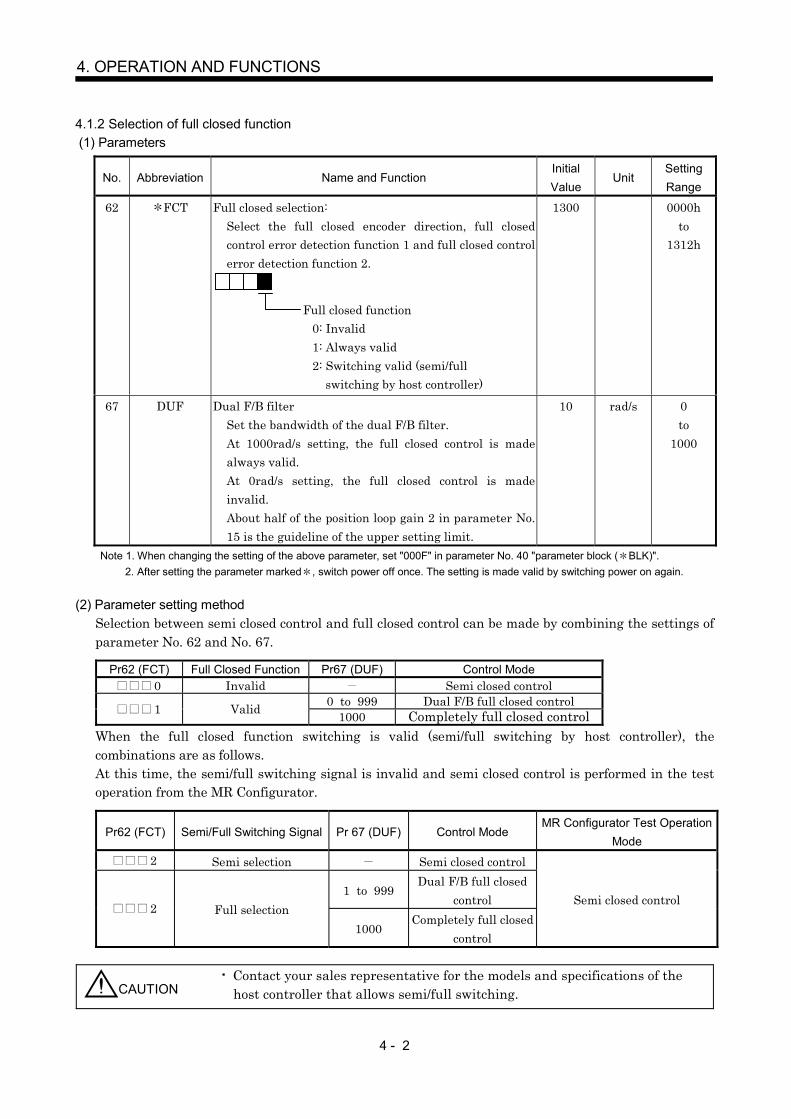
4 - 2
4. OPERATION AND FUNCTIONS
4.1.2 Selection of full closed function (1) Parameters
No. Abbreviation Name and FunctionInitialValue
UnitSettingRange
62 FCT Full closed selection:Select the full closed encoder direction, full closedcontrol error detection function 1 and full closed controlerror detection function 2.
Full closed function0: Invalid1: Always valid2: Switching valid (semi/full
switching by host controller)
1300 0000hto
1312h
67 DUF Dual F/B filterSet the bandwidth of the dual F/B filter.At 1000rad/s setting, the full closed control is madealways valid.At 0rad/s setting, the full closed control is madeinvalid.About half of the position loop gain 2 in parameter No.15 is the guideline of the upper setting limit.
10 rad/s 0to
1000
Note 1. When changing the setting of the above parameter, set "000F" in parameter No. 40 "parameter block ( BLK)".2. After setting the parameter marked , switch power off once. The setting is made valid by switching power on again.
(2) Parameter setting methodSelection between semi closed control and full closed control can be made by combining the settings ofparameter No. 62 and No. 67.
Pr62 (FCT) Full Closed Function Pr67 (DUF) Control Mode 0 Invalid Semi closed control
0 to 999 Dual F/B full closed control 1 Valid 1000 Completely full closed controlWhen the full closed function switching is valid (semi/full switching by host controller), thecombinations are as follows.At this time, the semi/full switching signal is invalid and semi closed control is performed in the testoperation from the MR Configurator.
Pr62 (FCT) Semi/Full Switching Signal Pr 67 (DUF) Control ModeMR Configurator Test Operation
Mode 2 Semi selection Semi closed control
1 to 999Dual F/B full closed
control 2 Full selection1000
Completely full closedcontrol
Semi closed control
CAUTION Contact your sales representative for the models and specifications of thehost controller that allows semi/full switching.
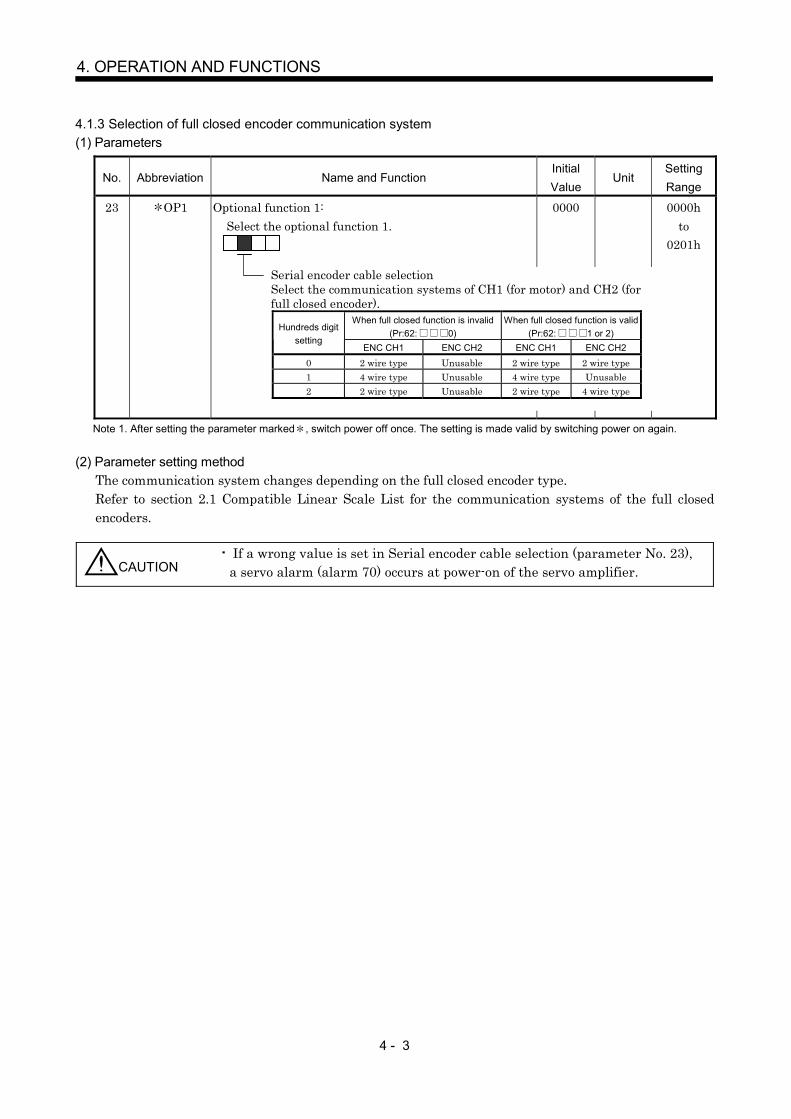
4 - 3
4. OPERATION AND FUNCTIONS
4.1.3 Selection of full closed encoder communication system(1) Parameters
No. Abbreviation Name and FunctionInitialValue
UnitSettingRange
23 OP1 Optional function 1:Select the optional function 1.
0000 0000hto
0201h
Note 1. After setting the parameter marked , switch power off once. The setting is made valid by switching power on again.
(2) Parameter setting methodThe communication system changes depending on the full closed encoder type.Refer to section 2.1 Compatible Linear Scale List for the communication systems of the full closedencoders.
CAUTION If a wrong value is set in Serial encoder cable selection (parameter No. 23),a servo alarm (alarm 70) occurs at power-on of the servo amplifier.
Serial encoder cable selectionSelect the communication systems of CH1 (for motor) and CH2 (forfull closed encoder).
When full closed function is invalid(Pr:62: 0)
When full closed function is valid(Pr:62: 1 or 2)
Hundreds digitsetting
ENC CH1 ENC CH2 ENC CH1 ENC CH20 2 wire type Unusable 2 wire type 2 wire type1 4 wire type Unusable 4 wire type Unusable2 2 wire type Unusable 2 wire type 4 wire type
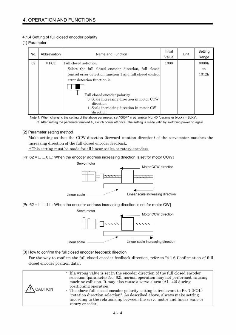
4 - 4
4. OPERATION AND FUNCTIONS
4.1.4 Setting of full closed encoder polarity(1) Parameter
No. Abbreviation Name and FunctionInitialValue
UnitSettingRange
62 FCT Full closed selectionSelect the full closed encoder direction, full closedcontrol error detection function 1 and full closed controlerror detection function 2.
Full closed encoder polarity0: Scale increasing direction in motor CCW
direction1: Scale increasing direction in motor CW
direction
1300 0000hto
1312h
Note 1. When changing the setting of the above parameter, set "000F" in parameter No. 40 "parameter block ( BLK)".2. After setting the parameter marked , switch power off once. The setting is made valid by switching power on again.
(2) Parameter setting methodMake setting so that the CCW direction (forward rotation direction) of the servomotor matches theincreasing direction of the full closed encoder feedback.
This setting must be made for all linear scales or rotary encoders.
[Pr. 62 = 0 : When the encoder address increasing direction is set for motor CCW]
Linear scale
Servo motorMotor CCW direction
Linear scale increasing direction
[Pr. 62 = 1 : When the encoder address increasing direction is set for motor CW]
Linear scale
Servo motorMotor CCW direction
Linear scale increasing direction
(3) How to confirm the full closed encoder feedback directionFor the way to confirm the full closed encoder feedback direction, refer to "4.1.6 Confirmation of fullclosed encoder position data".
CAUTION
If a wrong value is set in the encoder direction of the full closed encoderselection (parameter No. 62), normal operation may not performed, causingmachine collision. It may also cause a servo alarm (AL. 42) duringpositioning operation. The above full closed encoder polarity setting is irrelevant to Pr. 7 (POL)"rotation direction selection". As described above, always make settingaccording to the relationship between the servo motor and linear scale orrotary encoder.

4 - 5
4. OPERATION AND FUNCTIONS
4.1.5 Setting of full closed encoder electronic gear(1) Parameters
No. Abbreviation Name and Function InitialValue Unit Setting
Range65 FCM Full closed electronic gear numerator
Set the numerator of the electronic gear relative to thefull closed encoder pulse.
1 1to
6553566 FCD Full closed electronic gear denominator
Set the denominator of the electronic gear relative tothe full closed encoder pulse.
1 1to
65535Note 1. When changing the setting of the above parameter, set "000F" in parameter No. 40 "parameter block ( BLK)".
2. After setting the parameter marked , switch power off once. The setting is made valid by switching power on again.
(2) Parameter setting methodFor the full closed electronic gear setting, set the ratio of the full closed encoder feedback to the servomotor encoder feedback.
Make setting so that the full closed electronic gear FCDFCM does not fall outside the
FCDFCM
1100
1001 < < range.
This setting must be made for all linear scales or rotary encoders.[Setting example 1] When the servo motor is directly coupled with a ballscrew and the linear scale resolution is
0.05 m
Calculate the number of linear scale pulses per servo motor revolution.
[Setting example 2] When a rotary encoder at roll feed detection end is used for detection
When the pulley diameters or reduction ratios differ, consider that in calculation.For the rotary encoder, make calculation using the number of pulses multiplied by 4.
CAUTION If a wrong value is set in the linear scale electronic gear (parameter No. 65,66), normal operation may not performed.It may also cause a servo alarm (AL. 42) during positioning operation.
FCM
FCDNumber of servo motor encoder pulses per servo
Number of full closed encoder pulses per servo
Servo motor
Linear scale
<Conditions>Servo motor resolution : 131072pulse/revBallscrew lead : 4mmLinear scale resolution : 0.05 m
FCM
FCD
131072
80000
1024
625
Ballscrew lead / linear scale resolution 4mm/0.05 m 80000pluse
Servo motorPulley diameter d2 20mm
Pulley diameter d1 30mm
Rotary encoder5000pulse/rev
<Conditions>Servo motor resolution : 131072pulse/revServo motor side pulley diameter : 30mmRotary encoder side pulley diameter : 20mmRotary encoder resolution : 5000pulse/rev
(20000 pulses/rev after multiplication by 4)
FCM
FCD
131072 20
20000 30
8192
1875

4 - 6
4. OPERATION AND FUNCTIONS
4.1.6 Confirmation of full closed encoder position dataCheck the full closed encoder mounting and parameter settings for any problems.
POINTDepending on the check items, the MR Configurator may be used.Refer to "4.6 About Setup" for the data displayed on the MR Configurator.
[Check items]When checking the following items, the full closed control mode must be selected by setting parameterNo. 62 and No. 67.
For the control mode setting, refer to "4.1.2 Selection of full closed function".
No. Check Item Checking Method/Description1 Read of full closed encoder position data With the full closed encoder in a normal state (mounting,
connection, etc.), the cumulative feedback pulse 2 (full closedencoder side) value is counted normally when the full closedencoder is moved.
2 Read of full closed encoder scale home position(reference mark, Z phase)
With the scale home position (reference mark, Z phase) ofthe full closed encoder in a normal state (mounting,connection, etc.), the within-full-one-revolution position (fullclosed encoder side) value is cleared to 0 when the scalehome position (reference mark, Z phase) is passed throughby moving the full closed encoder.
3 Confirmation of full closed encoder feedbackdirection(Setting of full closed encoder polarity)
Confirm the full closed encoder feedback direction at thewithin-full-one-revolution position (full closed encoder side) bymoving the device (full closed encoder) manually in a servooff state.When the servo motor and full closed encoder feedbackdirections match, running the servo motor in the CCWdirection (counterclockwise as viewed from the shaft end)increases the within-full-one-revolution position (full closedencoder side), and running the servo motor in the CWdirection (clockwise as viewed from the shaft end) decreasesthe within-full-one-revolution position (full closed encoder side).When the servo motor and full closed encoder directions donot match, operation is performed oppositely.
4 Setting of full closed electronic gear When the servo motor and full closed encoders operatesynchronously, the cumulative feedback pulse (motor encoderside) and cumulative feedback pulse 2 (full closed encoderside) values increase in accordance with the setting ratio ofthe full closed electronic gear (FCM/FCD).[Confirmation example]When the servo motor is directly coupled with a ballscrew and thelinear scale resolution is 1.0 m
Motor encoder resolution 131072pullse/revBallscrew lead 4.0mmLinear scale resolution 1.0 mWhen the movement is equivalent to one servo motor revolution(machine end 4.0mm)Cumulative feedback pulse 2 (full closed encoder side) 4000 pulses
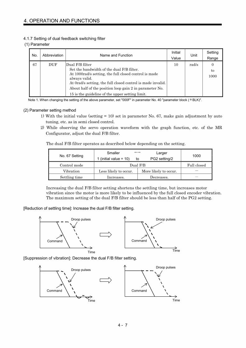
4 - 7
4. OPERATION AND FUNCTIONS
4.1.7 Setting of dual feedback switching filter (1) Parameter
No. Abbreviation Name and FunctionInitialValue
UnitSettingRange
67 DUF Dual F/B filterSet the bandwidth of the dual F/B filter.At 1000rad/s setting, the full closed control is madealways valid.At 0rad/s setting, the full closed control is made invalid.About half of the position loop gain 2 in parameter No.15 is the guideline of the upper setting limit.
10 rad/s 0to
1000
Note 1. When changing the setting of the above parameter, set "000F" in parameter No. 40 "parameter block ( BLK)".
(2) Parameter setting method1) With the initial value (setting = 10) set in parameter No. 67, make gain adjustment by auto
tuning, etc. as in semi closed control.2) While observing the servo operation waveform with the graph function, etc. of the MR
Configurator, adjust the dual F/B filter.
The dual F/B filter operates as described below depending on the setting.
No. 67 SettingSmaller
1 (initial value = 10) toLarger
PG2 setting/21000
Control mode Dual F/B Full closedVibration Less likely to occur. More likely to occur.
Settling time Increases. Decreases.
Increasing the dual F/B filter setting shortens the settling time, but increases motorvibration since the motor is more likely to be influenced by the full closed encoder vibration.The maximum setting of the dual F/B filter should be less than half of the PG2 setting.
[Reduction of settling time]: Increase the dual F/B filter setting.
[Suppression of vibration]: Decrease the dual F/B filter setting.
Droop pulses
Time
Command
Droop pulses
Time
Command
Droop pulsesDroop pulses
Time
Command
Time
Command

4 - 8
4. OPERATION AND FUNCTIONS
4.2 Home position return operation
4.2.1 General precautionsHome position return operation is all performed according to the full closed encoder feedback data,independently of the full closed encoder type. It is irrelevant to the Z-phase position of the motor encoder.In the case of a home position return using a dog signal, the scale home position (reference mark) must bepassed through when an incremental type linear scale is used, or the Z phase be passed through when arotary encoder is used, during a period from a home position return start until the dog signal turns off.
4.2.2 Full closed encoder types and home position return methods(1) About proximity dog type home position return using absolute linear scale Serial I/F
When an absolute linear scale is used, the home position reference position is the position per motorencoder resolution relative to the scale home position (absolute position data = 0).In the case of a proximity dog type home position return, the nearest position after proximity dog OFFis the home position.The scale home position may be set in any position.
Home position return speed
Creep speed
Home position return direction
Scale home position
Home positionreturn operation
Proximity dogsignal
Machine position
Home position
ONOFF
Home positionreference position
Equivalent to one motor encoder revolution

4 - 9
4. OPERATION AND FUNCTIONS
(2) About proximity dog type home position return using incremental linear scale Serial I/F General-purpose pulse outputWhen an incremental linear scale is used, the home position is the position per motor encoderresolution relative to the scale home position (reference mark) passed through first after a homeposition return start.In the case of a proximity dog type home position return, the nearest position after proximity dog OFFis the home position.Set one scale home position in the full stroke, and set it in the position that can always be passedthrough after a home position return start.
If a home position return is started at the position where the scale home position (reference mark)does not exist in the home position return direction, a home position return error occurs in thecontroller (the error definition changes depending on the controller type). When starting a homeposition return at the position where the scale home position (reference mark) does not exist in thehome position return direction, move the axis up to the stroke end on the side opposite to the homeposition return direction by jog operation, etc. of the controller once, then make a home positionreturn.
CAUTION To execute a home position return securely, start a home position returnafter moving the axis to the opposite stroke end by jog operation, etc. of thecontroller. To execute a home position return securely, start a home position ret Ahome position return cannot be made if the incremental linear scale doesnot have a scale home position (reference mark). Always provide a scalehome position (reference mark). (One place in the full stroke)
Home position return speed
Creep speed
Home position return direction
Scale home position
Home position return
Proximity dogsignal
Machine position
Home position
ONOFF
Home positionreference position
Equivalent to one motor encoderrevolution
Home position return speed
Creep speed
Home position return direction
Scale home position
Home position returni
Proximitydogsignal
Machine position
Home position
ONOFF
Stroke end
Jog operation
Home position return enabled Home position return disabled area

4 - 10
4. OPERATION AND FUNCTIONS
[Precautions]Note the following if the system uses the positioning module (QD75M) or VME bus Position Board (MR-MC01)as a position controller.
The scale home position (reference mark) has some width in the region where the signal turns on.
The signal ON width changes depending on the used linear scale.Contact the scale manufacturer for details.
The positioning module (QD75M) or VME bus Position Board (MR-MC01) determines the home positionreference position when the scale home position (reference mark) is passed through first after power-on ofthe servo amplifier. Therefore, a lag equivalent to the scale home position signal width is produced in thehome position reference position depending on the direction in which the scale home position (referencemark) is passed through.
Therefore, when it is desired to always make a home position return to the same position without a lagequivalent to the scale home position signal width, a home position return must be performed so that thescale home position is always passed through in the same direction.The following indicates a home position return method in which a lag equivalent to the scale homeposition signal width is not produced in the positioning module (QD75M) or VME bus Position Board(MR-MC01). [Home position return method in which lag equivalent to scale home position signal width is not produced]
(a) Move the linear servo motor to the position where the stroke end signal on the side opposite to thehome position return direction turns on.
(b) Perform the power-on reset of the servo amplifier or reset the controller.(c) Switch on the servo and make a home position return.
Scale home positionsignal
ONOFF
Signal ON width
Scale home positionONOFF
Signal ON width
Home positionreference position( Passed throughin direction)
Home positionreference position( Passed throughin direction)
Lag equivalent to scale home position signal ONwidth is produced.
Equivalent to one motorencoder revolution
Equivalent to one motorencoder revolution
Machine position
Stroke end Scale home position Home position
Stroke end
Home position return direction
Creep speed
Home position return speed
Scale home position
Home position return operation
Proximity dogsignal
Machine position
Home position
ONOFF

4 - 11
4. OPERATION AND FUNCTIONS
SUPPLEMENT The positioning module (QD75M) and VME bus Position Board (MR-MC01) are scheduled for modification to operate like the othercontrollers.Contact your sales representative for the modification time andcompatible versions.
CAUTION The home position return retry function of the positioning module (QD75M)cannot be used.

4 - 12
4. OPERATION AND FUNCTIONS
(3) About proximity dog type home position return using rotary encoderSerial I/F General-purpose pulse output
The home position using a rotary encoder as a full closed encoder is as described below. It is theposition per motor encoder resolution, starting at the position where the Z phase of the full closedencoder is passed through first after power-on of the servo amplifier.
[Precautions]Precautions for passage of Z phase
The home position reference position is set relative to the Z phase position of the full closed encoderthat is passed through first after power-on of the servo amplifier.In Case A and Case B where the power-on position differs as shown below, the power-on position mustbe noted since the axis cannot stop at the same home position return position.
Servo amplifierpower-on position
Machine position
Home position
Home positionreference position
Full closedencoder Z-phase signal
ONOFF
Equivalent to one motor encoder revolution
Home position reference is position permotor encoder resolution relative to Z-phasesignal of full closed encoder that was passedthrough first after power-on of servoamplifier.
Servo amplifierpower-on position
Home positionreturnoperation
Home position
Home positionreferenceposition
Full closedencoder Z-phase signal
ONOFF
Equivalent to one motor encoder revolution
Home position return speedCreep speed
Proximity dogsignal
ONOFF
Servo amplifierpower-on position
Home positionreturnoperation Home position
Home positionreferenceposition
Home positionreturn speed Creep speed
Equivalent to one motor encoder revolution
Case
Case

4 - 13
4. OPERATION AND FUNCTIONS
[Method for always making home position return to the same position](a) Move the linear servo motor to the position where the stroke end signal on the side opposite to the
home position return direction turns on.
(b) Perform the power-on reset of the servo amplifier or reset the controller.(c) Switch on the servo and make a home position return.
Machine position
Stroke end Scale home position Home position
Stroke end
Home position return speed
Creep speed
Home position return direction
Scale home position
Home position return operation
Proximity dogsignal
Machine position
Home position
ONOFF

4 - 14
4. OPERATION AND FUNCTIONS
(4) About data setting type count type 2) (QD75M) Common to all full closed encoders
In the data setting type/count type 2) (QD75M) home position return method, a home position returncan be normally made if the home position has been passed through (in either direction) before start ofa home position return, since a scale home position (reference mark) or the Z-phase signal of a rotaryencoder is not required.When the linear scale used does not have a scale home position (reference mark) or the machine hasno distance of one motor encoder revolution until the Z phase of the rotary encoder is passed through,a home position return can be made by changing the parameter (Pr. 33 "home position settingcondition selection") setting if the home position is not yet passed through.

4 - 15
4. OPERATION AND FUNCTIONS
4.3 Operation from controllerThe full closed control compatible amplifier can be used with any of the following controllers.
Classification Model RemarksA17 SHCPU, A173UHCPUA273UHCPU (-S3)Motion controllerQ17 CPU
Speed control (II) instructions (VVF, VVR) cannot be used.
Positioning module QD75M AD(A1SD)75M cannot be used.Home position return must be made with care.
MR-MC10 (PCI bus compatible)MR-MC2 (CPCI bus compatible)MR-MC30 (ISA bus compatible)Position BoardMR-MC01 (VME bus compatible) Home position return must be made with care.
Note. An ABS type linear scale is required to configure an absolute position system.The battery (MR-BAT) need not be fitted to the servo amplifier.
4.3.1 Operation from controllerPositioning operation from the controller is basically performed like the standard model servo.However, some parameter settings and home position return operation change depending on thecontroller type.
4.3.2 Controller settingWhen using full closed control, make the following setting.Set the other servo parameters and control parameters as in the standard servo.
(1) Motion controller, positioning moduleAfter writing parameter No. 23, 33, 62, 65, 66, and 68 to the servo amplifier, turn off the power supplyand then on again to make the setting valid. (For motion controller, resetting makes the servoamplifier setting valid.)
SettingsMotion controller Positioning moduleSetting Item A17 SH, A173UH, A273UH
Q17 QD75M
Command resolution Motor encoder resolution unitAmplifier setting MR-J2S- BMotor setting Automatic setting
Serial encoder cable selection(parameter No. 23)
Setting is necessary only when a 4wire type linear scale is used.Contact your sales representativefor the setting method.
Home position setting condition selection(parameter No. 33)
Contact your sales representativefor the setting method.
Full closed selection (parameter No. 62)Full closed control error detection 1 (parameter No. 63)Full closed control error detection 2 (parameter No. 64)Full closed electronic gear numerator(parameter No. 65)Full closed electronic gear denominator(parameter No. 66)Dual F/B filter (parameter No. 67)
Servoparameters
Full closed selection 2 (parameter No. 68)
Set using MR Configurator.
Set using sequenceladder.
Unit setting mm/inch/degree/pulsePositioningcontrolparameters
Moving distance per pulse (AP, AL, AM)Number of pulses per revolution (AP)Moving distance per revolution (AL)Unit multiplying factor (AM)
Set AP, AL and AM as usual with motor encoderresolution.
SUPPLEMENT In the future, the Q motion controller (Q17 ) is scheduled to allow theservo parameter Pr. 40 to Pr. 75 settings to be changed from theperipheral software.Contact your sales representative for the modification time andcompatible versions.

4 - 16
4. OPERATION AND FUNCTIONS
[Precautions]The positioning module (QD75M) controls the servo parameters No. 0 to 75. Therefore, when setting anyof the servo parameters up to No. 75, change the buffer memory setting of the positioning module in asequence program.If the settings of the parameters No. 0 to 75 are changed using the MR Configurator, they are notreflected on the positioning module.
[Reference sequence program]Example of writing the servo parameters (No. 62 to 67) of Axis No. 1
The flash ROM has a restriction on the write count. Therefore, when setting data using a sequenceprogram every time, for example, do not write data to the flash ROM.When controlling multiple axes, write the parameters to all axes.
(2) Position BoardSettings
Position BoardSetting ItemMR-MC01 MR-MC10, MR-MC2 ,
MR-MC30Command resolution Motor encoder resolution unit
Motor type (parameter No. 3) 0080h (131072)(Add 0603h)
0080h (Automatic setting)(Add 0414h)
Serial encoder cable selection(parameter No. 23)
Setting is necessary only when a 4 wire typelinear scale is used.
Home position setting condition selection(parameter No. 33) Set as required.Full closed selection (parameter No. 62)Full closed control error detection 1(parameter No. 63)Full closed control error detection 2(parameter No. 64)Full closed electronic gear numerator(parameter No. 65)Full closed electronic gear denominator(parameter No. 66)Dual F/B filter (parameter No. 67)
Servoparameters
Full closed selection 2 (parameter No. 68)
Set using MR Configurator.
Home position return option (OPZ1) No setting 1 hControlparameters Electronic gear setting (CMX, CDV) Set as usual with motor encoder resolution.
TOP H0 K30162 H1302 K1
TOP H0 K30163 K1000 K1
TOP H0 K30164 K50 K1
TOP H0 K30165 K20 K1
TOP H0 K30166 K1 K1
TOP H0 K30167 K10 K1
T30K5
Y0T30
Write conditionPr. 62 setting
Pr. 63 setting
Pr. 64 setting
Pr. 65 setting
Pr. 66 setting
Pr. 67 setting
Write waiting timer
PLC ready signal
TOP H0 K1900 K1 K1 Write to flash ROM

4 - 17
4. OPERATION AND FUNCTIONS
4.4 Functions
4.4.1 Full closed control error detectionIf full closed control becomes instable for some reason, the speed at servo motor end may increaseabnormally.The full closed control error detection function is a protective function designed to pre-detect it and stopoperation.The full closed control error detection function has two different detection methods, speed difference andposition difference, and errors are detected only when the corresponding functions are made valid bysetting Full closed selection (parameter No. 62).The detection level setting can be changed using the parameters (No. 63, 64).
(1) Parameters
No. Abbreviation Name and FunctionInitialValue
UnitSettingRange
62 FCT Full closed selection:Select the full closed encoder direction, full closedcontrol error detection function 1 and full closed controlerror detection function 2.
Full closed control error detection function0: Invalid1: Full closed control error detection
function 1 valid2: Full closed control error detection
function 2 valid3: Full closed control error detection
functions 1 and 2 both valid
1300 0000hto
1312h
63 BC1 Full closed control error detection 1Set the speed difference error detection level of Fullclosed control error detection 1.Whether this function is valid or invalid can be selectedusing parameter No. 62 (FCT).1 to permissible speed
400 r/min 1to
permissiblespeed
64 BC2 Full closed control error detection 2Set the position difference error detection level of Fullclosed control error detection 2.Whether this function is valid or invalid can be selectedusing parameter No. 62 (FCT).
10 0.1rev 1to
2000
Note 1. When changing the setting of the above parameter, set "000F" in parameter No. 40 "parameter block ( BLK)".2. After setting the parameter marked , switch power off once. The setting is made valid by switching power on again.
(2) Linear servo control error detection function
Example of linearscale
Servo motor
1) Motor end F/B speed (r/min)2) Motor end F/B position (pulse)
3) Full closed end F/B speed (r/min)4) Full closed end F/B position (pulse)(Motor end equivalent value)

4 - 18
4. OPERATION AND FUNCTIONS
(a) Speed difference error detectionIf there is a difference of not less than the setting (1 to permissible speed, r/min) between 1) motorend F/B speed and 3) full closed end F/B speed as a result of comparison, a stop is made due to analarm (AL42). In the default setting of the parameter, the error level is 400r/min.
(b) Position difference error detectionIf there is a difference of not less than the setting (0.1 to 200.0rev) between 2) motor end F/Bposition and 4) full closed end F/B position as a result of comparison, a stop is made due to analarm (AL42). In the default setting of the parameter, the error level is 1.0rev.
In the default settings of the parameters, speed difference error detection and position differenceerror detection are both valid.
4.4.2 Auto tuning functionThe auto tuning function is the same as that of the standard servo.For full information, refer to the Instruction Manual of the MR-J2S- B standard model.
4.4.3 Machine analyzer functionThe machine analyzer function of the MR Configurator is the same as that of the standard servo.For full information, refer to the Instruction Manual of the MR-J2S- B standard model.This function is activated by the feedback of the motor encoder. It is irrelevant to the full closed encoder.
4.4.4 Test operation
POINTWhen performing test operation using the MR Configurator, it isnecessary to reset the power supply after setting the axis number of theservo amplifier to "F".
Test operation can be performed by combining the MR Configurator that runs on the personal computerand the servo amplifier.The full closed control compatible amplifier cannot use motor-less operation.
Function Item Usability Remarks
Jog operation UsablePerformed by the feedback of the motor encoder.It is irrelevant to the full closed encoder.
Positioningoperation
Usable
Program operation Usable
In a semi closed control/full closed control state, operation is performed inthe control mode states as set in parameter No. 62, No. 67.When full closed function switching is valid (semi/full switching by hostcontroller), semi closed control is always valid.
DO forced output Usable Same as the standard servo function.
Test operation
Motor-less operation Unusable Not supported.

4 - 19
4. OPERATION AND FUNCTIONS
4.5 Absolute position detection system
An ABS type linear scale is necessary to configure an absolute position detection system under full closedcontrol using a linear scale.In this case, absolute value data are backed up on the linear scale side, and therefore, the encoder battery(MR-BAT) need not be installed to the servo amplifier.
POINT When configuring an absolute position detection system with this servoamplifier under semi closed control, the encoder battery (MR-BAT) mustbe installed to the servo amplifier like the standard amplifier.At this time, the option cable (MR-J2SCLCBL02M-P-H) cannot be used.Connect the encoder cable of the motor encoder directly to the servoamplifier.
[Precautions]Make setting to make Absolute position detection valid in the servo parameter (Pr. 1 0001). The systemcan be used in the following limited conditions.
(1) Using conditions1) Use an absolute type linear scale with the full closed encoder.2) Select Always full closed (Pr. 62 1).
(2) Absolute position detection range using encoder
Encoder Type Absolute Position Detection Enabled Range
Linear scale(Serial I/F)
Movable distance range of scale(within 32-bit absolute position data)
(3) Alarm detectionThe absolute position-related alarm (25) and warnings (92, 9F, E3) are not detected.

4 - 20
4. OPERATION AND FUNCTIONS
4.6 About the MR Configurator4.6.1 When current version of MR Configurator (MRZJW3-SETUP121 to -SETUP151 S/W: E0 version) is
usedThe following indicates how to check whether the full closed-related parameter settings are normal or notand whether the servo motor and full closed encoders operate normally or not.Select "MR-J2S-B" in the system setting of the MR Configurator. Opening the batch monitor screendisplays the following screen.
2
7
4
3
5
6
1
(1) Explanation of display itemsThe following table indicates the display items that are related to the servo motor and full closedencoders.
Symbol Name Explanation
1) Cumulative feedback pulse Feedback pulses from the servo motor encoder are counted and displayed.Click "Clear" to reset the value to 0.
2)Command pulse frequency Position command inputs from the command controller are counted and
displayed.Click "Clear" to reset the value to 0.
3) Within-one-revolution position The within-one-revolution position of the servo motor encoder is displayed.
4)ABS counter The multi-revolution counter (number of revolutions from home position) of the
servo motor encoder is displayed.The value is incremented or decremented by 1 per servo motor revolution.
5)
Regenerative load ratio ( read asCumulative feedback pulse 2)
Caution: The name does not matchwhat is monitored. The realregenerative load ratio is displayed onthe left side.
Feedback pulses from the full closed encoder are counted and displayed.The value is displayed in the pulse unit of the closed encoder.Click "Clear" to reset the value to 0.
6)
Bus voltage ( read as Within-full-one-revolution position)
Caution: The name does not matchwhat is monitored. The real busvoltage is displayed two lines above.
The within-one-revolution position of the full closed encoder is displayed.In the case of an INC linear scale, the Z-phase counter is displayed. The valueis counted up from 0 relative to the home position (reference mark). The valueis displayed in the pulse unit of the closed encoder.In the case of an ABS linear scale, the virtual within-one-revolution position(equivalent to lower 17 bits of the conversion result of 32-bit absolute positiondata into the motor end unit, 0 to 131071) is displayed.
7)
Peak bus voltage ( read as Full ABScounter)
Caution: The name does not matchwhat is monitored.
The multi-revolution counter (number of revolutions from home position) of thefull closed encoder is displayed.In the case of an ABS linear scale, the virtual multi-revolution counter(equivalent to lower 15 bits of the conversion result of 32-bit absolute positiondata into the motor end unit, 0 to 32767) is displayed.

4 - 21
4. OPERATION AND FUNCTIONS
4.6.2 When full closed compatible MR Configurator (MRZJW3-SETUP151 S/W: E1 version or later) is usedSelect "MR-J2S-B full closed" in the system setting of the MR Configurator.
(1) Batch monitor screen
This screen is designed to display Cumulative feedback pulse 2, Within-full-one-revolution positionand Full ABS counter as formal names.Refer to above Section 4.7.1 for the explanation of what are displayed.
(2) Diagnosis - full closed diagnosis screenThe position-related monitor indications and parameters on the full closed function are all displayedon a single screen.
(The explanation is given on the next page.)

4 - 22
4. OPERATION AND FUNCTIONS
[Explanation of display items and functions]For the monitor display item, click "Start monitor" to read it continuously from the amplifier. Click"Stop monitor" to stop read.For the parameter item, click "Read parameter" to read it from the amplifier, and click "Writeparameter" to write.
Name Explanation
Command pulsefrequency
Commands from the host controller are counted and displayed.Click "Clear" to reset the value to 0.
Cumulative feedbackpulse
Feedback pulses from the servo motor encoder are counted and displayed.Click "Clear" to reset the value to 0.
Droop pulses When the full closed function is "invalid", a deviation from the command that uses the servomotor encoder as F/B is displayed.When the full closed function is "valid" or "semi/full switching", a deviation from thecommand that uses the closed encoder as F/B is displayed.
Cumulative feedbackpulse 2
Feedback pulses from the full closed encoder are counted and displayed.The value is displayed in the pulse unit of the closed encoder.Click "Clear" to reset the value to 0.
Encoder data The data of the closed end encoder are displayed.The displayed data change depending on the closed encoder type.
ID : The ID number of the encoder is displayed.Data 1 : In the case of the INC type, a counter starting at power-on is displayed.
In the ABS type linear encoder, absolute position data is displayed.In the case of the ABS type rotary encoder, a multi-revolution counter isdisplayed.
Data 2 : In the case of the INC type, the distance (number of pulses) from the referencemark (Z phase) is displayed.In the ABS type linear encoder, 00000000 is displayed.In the case of the ABS type rotary encoder, a cycle counter is displayed.
Polarity A or sign is displayed according to the full closed encoder polarity specified in the fullclosed selection parameter.Note: Full closed encoder polarity
is displayed when the setting is "0: Address increasing direction for motor CCW".Z-phase pass state When the full closed function is "invalid", the Z-phase pass state of the servo motor encoder
is displayed.When the full closed function is "valid" or "semi/full switching", the Z-phase pass state ofthe closed encoder is displayed.
Full closed switchingdevice
Displayed only when "semi/full switching" is selected for the full closed function.The switching device selection command state and the internal state during selection aredisplayed.
Parameter The parameter related to the full closed control is displayed.Its setting can be changed and the new value can be written to the servo amplifier.The related parameters are as follows.
Electronic gear : Pr. 6Dual F/B filter : Pr. 67FCM : Pr. 65FCD : Pr. 66Full closed selection : Pr. 62, 63, 64

5 - 1
5. PARAMETERS
5 PARAMETERS
5.1 Parameter list
SUPPLEMENTFor any parameter flagged with an asterisk (*), set the parameter valueand switch power off, then switch it on again to make the setting valid.Parameter is set at the timing when communication is establishedbetween the servo system controller and the servo amplifier(displayed in b*).Subsequently, turn off the power supply of servo amplifier and then onagain.
Class No. Abbreviation Name Initial Value Unit Remarks
Bas
ic p
aram
eter
s
0102030405060708091011
AMSREG
FBPPOLATURSPTLPTLN
Amplifier settingRegenerative resistorFor manufacture settingFor manufacture settingFor manufacture settingFeedback pulseRotation direction selectionAuto tuningServo response level settingForward rotation torque limit valueReverse rotation torque limit value
0000000000800000
100
00010005
300300
%%
Adj
ustm
ent p
aram
eter
s
12
1314151617181920212223242526
GD2
PG1VG1PG2VG2VIC
NCHFFCINP
MBRMODOP1OP2LPF
Ratio of load inertia moment to servo motor inertiamomentPosition loop gain 1Speed loop gain 1Position loop gain 2Speed loop gain 2Speed integral compensationMachine resonance suppression filterFeed forward gainIn-position rangeElectromagnetic brake sequence outputAnalog monitor outputOptional function 1Optional function 2Low-pass filter/adaptive vibration suppression controlFor manufacture setting
70
35177
35817
4800
1000
00010000000000000000
0.1 times
rad/srad/srad/srad/smsec
%pulsemsec
Exp
ansi
on p
aram
eter
s
2728293031323334353637383940
MO1MO2
ZSPERZOP5OP6VPI
VDC
ENR
BLK
Monitor output 1 offsetMonitor output 2 offsetFor manufacture settingZero speedError excessive alarm levelOptional function 5Optional function 6PI-PID switching position droopFor manufacture settingSpeed differential compensationFor manufacture settingEncoder output pulseFor manufacture settingParameter write inhibit
00
00015080
00000000
00
98000104000
00000
mvmv
r/min0.1rev
pulse
pulse/rev
The parameters marked are valid only at power-on.

5 - 2
5. PARAMETERS
Class No. Abbreviation Name Initial Value Unit Remarks
Exp
ansi
on p
aram
eter
s 2
41424344454647484950515253545556575859606162
63
64
65
66
67
6869707172737475
OPC
FCT
BC1
BC2
FCM
FCD
DUF
FC2
For manufacture settingFor manufacture settingFor manufacture settingFor manufacture settingFor manufacture settingFor manufacture settingFor manufacture settingFor manufacture settingFor manufacture settingFor manufacture settingFor manufacture settingFor manufacture settingFor manufacture settingFor manufacture settingFor manufacture settingFor manufacture settingFor manufacture settingFor manufacture settingFor manufacture settingOptional function CFor manufacture settingFull closed selection (additional function unavailable forthe standard model)Full closed control error detection 1 (additional functionunavailable for the standard model)Full closed control error detection 2 (additional functionunavailable for the standard model)Full closed electronic gear numerator (additionalfunction unavailable for the standard model)Full closed electronic gear denominator (additionalfunction unavailable for the standard model)Dual F/B filter (additional function unavailable for thestandard model)Full closed selection 2 (additional function unavailablefor the standard model)
50000000111
2050
000
000010
170
100100100
0000000000000000000000001300
400
10
1
1
10
00000000000
r/min
0.1rev
The parameters marked are valid only at power-on.
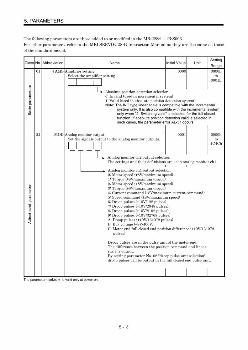
5 - 3
5. PARAMETERS
The following parameters are those added to or modified in the MR-J2S- B-S096.For other parameters, refer to the MELSERVO-J2S-B Instruction Manual as they are the same as thoseof the standard model.
Class No. Abbreviation Name Initial Value UnitSettingRange
Bas
ic p
aram
eter
s
01 AMS Amplifier settingSelect the amplifier setting.
0000 0000hto
0001h
Adj
ustm
ent p
aram
eter
22 MOD Analog monitor outputSet the signals output to the analog monitor outputs.
0001 0000hto
4C4Ch
The parameter marked is valid only at power-on.
Absolute position detection selection0: Invalid (used in incremental system)1: Valid (used in absolute position detection system)Note: The INC type linear scale is compatible with the incremental
system only. It is also compatible with the incremental systemonly when "2: Switching valid" is selected for the full closedfunction. If absolute position detection valid is selected insuch cases, the parameter error AL-37 occurs.
Analog monitor ch2 output selectionThe settings and their definitions are as in analog monitor ch1.
Analog monitor ch1 output selection0: Motor speed ( 8V/maximum speed)1: Torque ( 8V/maximum torque)2: Motor speed ( 8V/maximum speed)3: Torque ( 8V/maximum torque)4: Current command ( 8V/maximum current command)5: Speed command ( 8V/maximum speed)6: Droop pulses ( 10V/128 pulses)7: Droop pulses ( 10V/2048 pulses)8: Droop pulses ( 10V/8192 pulses)9: Droop pulses ( 10V/32768 pulses)A: Droop pulses ( 10V/131072 pulses)B: Bus voltage ( 8V/400V)C: Motor end full closed end position difference ( 10V/131072
pulses)
Droop pulses are in the pulse unit of the motor end.The difference between the position command and linearscale is output.By setting parameter No. 68 "droop pulse unit selection",droop pulses can be output in the full closed end pulse unit.
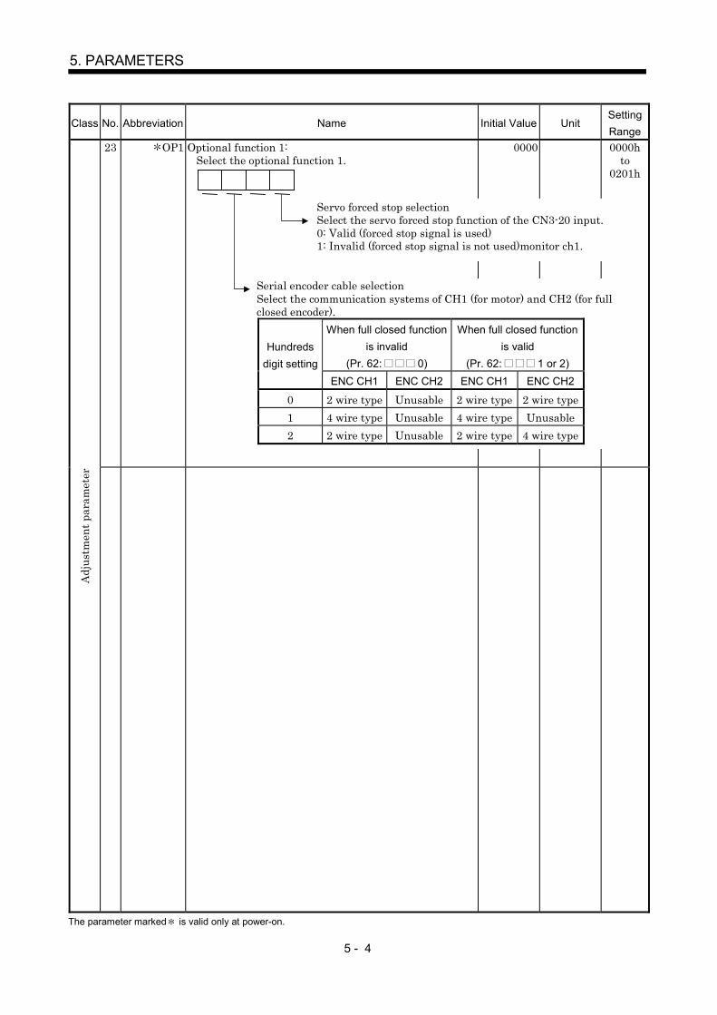
5 - 4
5. PARAMETERS
Class No. Abbreviation Name Initial Value UnitSettingRange
23 OP1 Optional function 1:Select the optional function 1.
0000 0000hto
0201h
Adj
ustm
ent p
aram
eter
The parameter marked is valid only at power-on.
Servo forced stop selectionSelect the servo forced stop function of the CN3-20 input.0: Valid (forced stop signal is used)1: Invalid (forced stop signal is not used)monitor ch1.
Serial encoder cable selectionSelect the communication systems of CH1 (for motor) and CH2 (for fullclosed encoder).
When full closed functionis invalid
(Pr. 62: 0)
When full closed functionis valid
(Pr. 62: 1 or 2)Hundreds
digit settingENC CH1 ENC CH2 ENC CH1 ENC CH2
0 2 wire type Unusable 2 wire type 2 wire type1 4 wire type Unusable 4 wire type Unusable2 2 wire type Unusable 2 wire type 4 wire type

5 - 5
5. PARAMETERS
Class No. Abbreviation Name Initial Value UnitSettingRange
33 OP6 Optional function 6:Select the optional function 6.
0000 0000hto
1110h
Exp
ansi
on p
aram
eter
s
38 ENR Encoder output pulse:Set the encoder output provided by the servo amplifierin terms of the number of output pulses per revolutionor a division ratio. This selection depends onparameter No. 33. Use the maximum output frequencywithin 1.3Mpulse/sec.
1) In the case of division ratio setting
Number of output pulsesequivalent to one motorrevolution
Number of encoder pulses equivalento one motor revolution
ENR setting2) In the case of output pulse setting
Number of output pulses equivalent to one motorrevolution ENR settingSet the above number of output pulses in terms of thenumber of pulses multiplied by 4 in AB phases.
Note: When the full closed function is made valid inparameter No. 62 (FCT) and the ABZ-phase pulseoutput of the full closed encoder is selected inparameter No. 68 (FC2), consider it as "equivalentto one motor revolution" "moving distance of thefull closed encoder equivalent to one revolution ofthe semi closed end motor".For example, when the linear scale of 0.1 mresolution is installed as the full closed encoder tomove 10mm per servo motor revolution,
1) On the assumption that the ENR setting is 20 fordivision ratio setting
Number of output pulsesfor 10mm movement
100000 (equivalent to onemotor revolution)
20500
2) On the assumption that the ENR setting is 20 foroutput pulse settingNumber of output pulses for 10mm movement 20
4000 0to
65535
The parameters marked are valid only at power-on.
Serial communication baud rate selection 0: 9600[bps]
Serial communication response delay time selection0: Invalid1: Valid, a replay is sent after a delay time of 888 sec or more
Encoder pulse output setting selection0: Output pulse setting1: Division ratio setting
Home position setting condition selectionSelect the condition under which a home position setting is made fromthe servo system controller.0: Motor Z-phase pass required after power on1: Motor Z-phase pass not required after power on
(Used in a data setting type home position return where the Zphase is not passed through.)
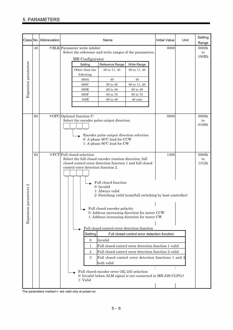
5 - 6
5. PARAMETERS
Class No. Abbreviation Name Initial Value UnitSettingRange
Exp
ansi
on p
aram
eter
s
40 BLK Parameter write inhibit:Select the reference and write ranges of the parameters.
0000 0000hto
100Eh
60 OPC Optional function C:Select the encoder pulse output direction.
0000 0000hto
0100h
E
xpan
sion
par
amet
ers
2
62 FCT Full closed selection:Select the full closed encoder rotation direction, fullclosed control error detection function 1 and full closedcontrol error detection function 2.
1300 0000hto
1312h
The parameters marked are valid only at power-on.
MR ConfiguratorSetting Reference Range Write Range
Other than thefollowing
00 to 11, 40 00 to 11, 40
000A 40 40000C 00 to 40 00 to 11, 40000E 00 to 40 00 to 40000F 00 to 75 00 to 75100E 00 to 40 40 only
Encoder pulse output direction selection0: A-phase 90 lead for CCW1: A-phase 90 lead for CW
Full closed function0: Invalid1: Always valid2: Switching valid (semi/full switching by host controller)
Full closed encoder polarity0: Address increasing direction for motor CCW1: Address increasing direction for motor CW
Full closed control error detection functionSetting Full closed control error detection function
0 Invalid1 Full closed control error detection function 1 valid2 Full closed control error detection function 2 valid3 Full closed control error detection functions 1 and 2
both valid
Full closed encoder error (AL-2A) selection0: Invalid (when ALM signal is not connected in MR-J2S-CLP01)1: Valid

5 - 7
5. PARAMETERS
Class No. Abbreviation Name Initial Value UnitSettingRange
63 BC1 Full closed control error detection 1:Set the speed difference error detection level of the fullclosed control error detection function 1. (Set in termsof the servo motor end-equivalent speed.)Whether this function is valid or invalid can be selectedusing parameter No. 62 (FCT).
400 r/min 1to
permissible
speed
64 BC2 Full closed control error detection 2:Set the position difference error detection level of thefull closed control error detection 2 function. (Set interms of the number of servo motor end-equivalentrevolutions.)Whether this function is valid or invalid can be selectedusing parameter No. 62 (FCT).
10 0.1rev 1to
2000
65 FCM Full closed electronic gear numerator:Set the numerator of the electronic gear relative to thefull closed encoder pulse.
1 1to
6553566 FCD Full closed electronic gear denominator:
Set the denominator of the electronic gear relative tothe full closed encoder pulse.
1 1to
6553567 DUF Dual F/B filter:
Set the bandwidth of the dual F/B filter.At 1000rad/s setting, the full closed control is madealways valid.At 0rad/s setting, the full closed control is made invalid.About half of the position loop gain 2 in parameter No.15 is the guideline of the upper setting limit.
10 rad/s 0to
1000
Exp
ansi
on p
aram
eter
s 2
68 FC2 Full closed selection 2:Select the functions related to full closed control.
0000 0000hto
0011h
The parameters marked are valid only at power-on.
Droop pulse unit selection0: Motor end pulse unit1: Closed end pulse unitWith this setting, the droop pulse unit of the MR Configuratorbatch monitor display, monitor graph data and analog monitoroutput can be selected.(Note: When the full closed function is invalid (including whenthe semi closed function is selected at the time of the switchingvalid setting), the motor end pulse unit is forcibly set.)
Pulse output setting0: ABZ phase pulses of the full closed encoder are output.1: ABZ phase pulses of the motor end encoder are output.(Note: When the full closed function is invalid (includingwhen the semi closed function is selected at the time ofthe switching valid setting), the ABZ phase pulses of themotor end encoder are forcibly output.)

5 - 8
5. PARAMETERS
MEMO

6 - 1
6. TROUBLESHOOTING
6 TROUBLESHOOTING6.1 Alarm listThe following protective functions are the alarms that differ from those of the standard model.For the other alarms, refer to the MELSERVO-J2S-B Specifications and Installation Guide andInstruction Manual since they are the same as those of the standard model.
Indication Name Definition Occurrence Factor Corrective ActionThe linear scale temperature is high.(Mitutoyo make linear scale)
Check the linear scaletemperature and contactthe scale manufacturer.
AL28 Full closedencoder error 2
Linear scale operatingenvironment was abnormal.
Reduction of linear scale signal level(Sony Precision Technology makelinear encoder)
Check the mounting stateof the linear scale.
Full closed encoder fault Contact the full closedencoder manufacturer.
Linear scale alarm Confirm the detailedinformation given inSection 6.2 and contactthe scale manufacturer.
The linear scale speed exceeded thespecification range.
Use the linear scale at thespeed within thespecification range.
Linear scale and detection headmounting position error
Adjust the linear scaleand detection headmounting positions.
Noise entry Take noise reductionmeasures.Contact the full closedencoder manufacturer.
The MR-J2S-CLP01 connector CN1Ais disconnected.
Connect it correctly.
AL2A Full closedencoder error 1
Full closed encoder (linearscale or ABZ phase pulse-specified encoder) is faulty.
ALM output of the full closedencoder (when ALM output detectionis valid in parameter No. 62)
Change the full closedencoder.
Full closed encoder failure Change the full closedencoder.
The polarity of the full closedencoder is set oppositely.
Check the mountingorientation of the fullclosed encoder.Reexamine the setting ofparameter No. 62.
AL42 Full closedcontrol errordetection
The setting of the full closed encoderelectronic gear is wrong.
Reexamine the settings ofparameter No. 65, 66.Check the mounting stateof the full closed encoder.
Full closed control errordetection function wasactivated.1) The difference between the
F/B speed of the full closedencoder and the F/B speedof the motor end encoderreached or exceeded thesetting of Pr. 63.
2) The motor shaft-equivalentdifference between the F/Bposition of the full closedencoder and the F/B positionof the motor end encoderreached or exceeded thesetting of Pr. 64.
The resolution setting for the fullclosed encoder is incorrect.
Set the resolution settingfor the full closed encodercorrectly.
The connector CN2 is disconnected. Connect it correctly.MR-J2S-CLP01 unit failure Change the unit.The internal setting switch (SW1) forMR-J2S -CLP01 unit is not closed.
Set correctly.
AL70 Full closedencodercommunicationerror 1
Error occurred incommunication between thefull closed encoder and servoamplifier. Full closed encoder cable failure Correct or change the
cable.MR-J2S-CLP01 unit failure Change the unit.Full closed encoder cable failure Correct or change the
cable.
AL71 Full closedencodercommunicationerror 2
Error occurred incommunication between thefull closed encoder and servoamplifier.
Full closed encoder cable wiringmistake (All of the A-, B- and Z-phase signal and power supply wiresare not yet connected. Especiallynote that the wiring of the MR-J2S-CLP01 unit Z-phase cannot beomitted.)
Reexamine the wiring.
The startup timing of 5V powersupply for the MR-J2S-CLP01 unit isslow.
Speed up the startuptiming of 5V power supplyfor the MR-J2S-CLP01unit.
Note: The above alarms are cleared by powering off the servo amplifier. They are not cleared by performing an alarm reset.

6 - 2
6. TROUBLESHOOTING
6.2 Scale error (AL. 2A) details classified by linear scale manufacturer
When the occurrence cause of alarm 2A is unknown, contact the linear scale manufacturer afterconfirming the scale error details in the following table on the basis of the alarm detail information of thealarm history display on the MR Configurator.
Scale Error (Alarm 2A) DetailsDetail
Information BitMitutoyo Sony Precision Technology Heidenhain Renishaw
Bit7 Optical overspeed Overspeed errorBit6 ROM RAM error OverspeedBit5 EEPROM error Encoder alarm EEPROM errorBit4 CPU error CPU errorBit3 Capacitive error ABS data errorBit2 Photoelectric error INC data error
Bit1Photoelectric capacitive
data mismatchEncoder warning
Scale level errorINC/ABS data mismatch error Level error
Bit0 Initialization error Initialization error
Example in which alarm 2A occurred on Mitutoyo make linear scale AT343A
Alarm details : 44h
When the alarm detail information of alarm 2A is 44h, bit 6 and bit 2 are on as indicated below,indicating that the ROM RAM error and photoelectric error occurred.Use this information when contacting the scale manufacturer.
bit7 bit6 bit5 bit4 bit3 bit2 bit1 bit044h = 0 1 0 0 0 1 0 0
4 4

7 - 1
7. OPTIONS AND AUXILIARY EQUIPMENT
7 OPTIONS AND AUXILIARY EQUIPMENT
7.1 CN2 wiring option cable (MR-J2SCLCBL02M-P-H)The internal wiring of the option cable (MR-J2SCLCBL02M-P-H) is as shown below.Explanation of connectorsCN2 connector : Connect to CN2 of the servo amplifier.MOTOR connector : Connect the encoder cable (e.g. MR-JCCBL M-H, MR-JHSCBL M-H,
MR-ENCBL M-H) of the servo motor.SCALE connector : Connect the serial communication encoder connector at the full closed end.
CN
2M
OTO
RS
CA
LE
1912201171761641491
P5LGP5LGMRMRRMDMDRMD2MDR2BATLGShield゙
CN2connector
10120-3000PE(connector)320-52F0-008(shell kit)(3M or equivalent)
18191220117171812
P5P5LGP5LGMRMRRP5LGLGShieldト
MOTORconnector
10220-0200EL (connector)10320-E2W0-008 (shell kit)(3M or equivalent)
1019122011717616912
P5P5LGP5LGMRMRRMDMDRBATLGLGShieldト
SCALEconnector
10220-0200EL (connector)10320-E2W0-008 (shell kit)(3M or equivalent)
200mm
Appearance
Wiring diagram

7 - 2
7. OPTIONS AND AUXILIARY EQUIPMENT
MEMO

REVISIONS
*The manual number is given on the bottom left of the back cover.
Print Data *Manual Number Revision
Feb., 2003 SH(NA)030035-A First editionJan., 2007 SH(NA)030035-B Chapter 2
Section 4.3. 2 (1)Section 5.1
Section 6.1
Change of connector type name manufactured by 3MOriginally 10120-3000VEAddition of sentenceAddition of sentenceChange of initial value for parameter No. 17 Originally 20Addition of cause for AL. 42Addition of cause for AL. 70Addition of cause for AL. 71

SH (NA) 030035-B (0701) MEE Printed in Japan Specifications subject to change without notice.This Instruction Manual uses recycled paper.
MODEL
MODELCODE
General-Purpose AC Servo
MR-J2S- B-PY096MR-J2S- B-S096(5.7kW)
MODEL
INSTRUCTION MANUAL
SSCNET Fully Closed Control Compatible
J2-Super Series
J2-Su
per S
eriesM
R-J2S
- B-P
Y096 M
R-J2S
- B-S
096(5.7kW) In
structio
n M
anu
al
HEAD OFFICE : TOKYO BLDG MARUNOUCHI TOKYO 100-8310
B
B


![400VAC Compatible MR-J2S- A4/B4 - Mitsubishi Electric€¦ · MR-J2S- A4/B4 SERVO AMPLIFIER SUPPLEMENTARY INSTRUCTION MANUAL ... 32 to 104 (non-freezing) [ ] 20 to 65 (non-freezing)](https://img.dokumen.tips/doc/110x75/5b069b237f8b9ae9628d4cfe/400vac-compatible-mr-j2s-a4b4-mitsubishi-a4b4-servo-amplifier-supplementary.jpg)