Embed Size (px)
Citation preview
1
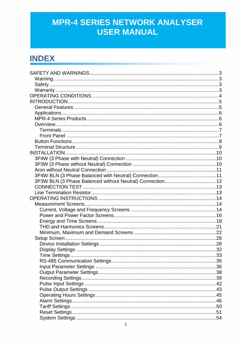
INDEX SAFETY AND WARNINGS ............................................................................................. 3
Warning ....................................................................................................................... 3
Safety .......................................................................................................................... 3
Warranty ...................................................................................................................... 3
OPERATING CONDITIONS ............................................................................................ 4
INTRODUCTION ............................................................................................................. 5
General Features ......................................................................................................... 5
Applications ................................................................................................................. 6
MPR-4 Series Products ............................................................................................... 6
Overview ...................................................................................................................... 6
Terminals ................................................................................................................. 7
Front Panel .............................................................................................................. 7
Button Functions .......................................................................................................... 8
Terminal Structure ....................................................................................................... 9
INSTALLATION ............................................................................................................. 10
3P4W (3 Phase with Neutral) Connection ................................................................. 10
3P3W (3 Phase without Neutral) Connection ............................................................ 10
Aron without Neutral Connection ............................................................................... 11
3P4W BLN (3 Phase Balanced with Neutral) Connection .......................................... 11
3P3W BLN (3 Phase Balanced without Neutral) Connection ..................................... 12
CONNECTION TEST ................................................................................................ 13
Line Termination Resistor .......................................................................................... 13
OPERATING INSTRUCTIONS ..................................................................................... 14
Measurement Screens ............................................................................................... 14
Current, Voltage and Frequency Screens .............................................................. 14
Power and Power Factor Screens.......................................................................... 16
Energy and Time Screens ...................................................................................... 18
THD and Harmonics Screens................................................................................. 21
Minimum, Maximum and Demand Screens ........................................................... 22
Setup Screen ............................................................................................................. 28
Device Installation Settings .................................................................................... 28
Display Settings ..................................................................................................... 32
Time Settings ......................................................................................................... 33
RS-485 Communication Settings ........................................................................... 35
Input Parameter Settings ....................................................................................... 36
Output Parameter Settings ..................................................................................... 38
Recording Settings ................................................................................................. 39
Pulse Input Settings ............................................................................................... 42
Pulse Output Settings ............................................................................................ 43
Operating Hours Settings ....................................................................................... 45
Alarm Settings ........................................................................................................ 46
Tariff Settings ......................................................................................................... 50
Reset Settings ........................................................................................................ 51
System Settings ..................................................................................................... 54
MPR-4 SERIES NETWORK ANALYSER USER MANUAL

2
Analog Output Settings .......................................................................................... 57
Reporting Screen ....................................................................................................... 60
TECHNICAL FEATURES AND APPENDIX .................................................................. 62
Technical Features .................................................................................................... 62
Measurement Menu Map 1 ........................................................................................ 64
Measurement Menu Map 2 ........................................................................................ 65

3
SAFETY AND WARNINGS
Warning
Failure to follow the instructions below may result in serious injury or death.
Cut all power before connecting the device.
Once the device is energized, do not remove the front panel.
Do not attempt to clean the device with a solvent or another similar agent. Use only a dry piece of
cloth.
Check the correct connections before energizing the device.
Contact your authorized seller in case of any problems with your device.
Device is only for panel mounting.
F Type fuse must be used and its current limit must be 1 A.
The manufacturing company is not responsible for the consequences resulting from failure to comply with these precautions.
Safety
Read the entire user manual before using the device.
A switch or circuit breaker must be connected between the network and the auxiliary supply of
the device.
Connected switch or circuit breaker must be in close proximity to the device.
Connected switch or circuit breaker must be marked as the disconnecting device for the equipment.
Warranty
Device has a 2 (two) year warranty. Any repairs on the device must be done only by the manufacturer. Otherwise, the device warranty will be void.

4
OPERATING CONDITIONS
Operating Conditions Range
Supply Voltage 45 ~ 265 VAC
Supply Frequency 45 ~ 65 Hz.
Maximum Measuring Current 5,5 A
Maximum Measuring Voltage 690 VAC (VLL)
Operating Temperature -5 ~ +55 ºC
Storing Temperature -25 ~ +70 ºC
Maximum Ambient Humidity 90%
Communication Speed 2400 ~ 115200 bps

5
INTRODUCTION
General Features
o Wide supply range o Custom FSTN display with backlight o 4 voltage measuring inputs o 4 current measuring inputs o 4 language options o 16MB internal memory o Real time clock o Alarm o Hour counters (Operating hour and total hour) o Communication via RS-485 o Module input: o Digital Input / Output
2 Digital Inputs 2 Digital Outputs 2 Digital Inputs + 2 Digital Outputs
Relay Output
2 relay outputs: 5A/250VAC; NO
Analog Output
2x 0/4 – 20mA outputs or 2x 0/2 – 10V outputs
Temperature Input
4x PTD or 2x thermo-couple inputs. Optionally 1 digital input + 1 digital output.
o Measured parameters: Current, Voltage, Power, Energy, THDI and THDV, Power factor and cosφ
o 96 x 96 panel mount o Event records storage and management o User password o Changing primary and secondary values of current and voltage transformers o Making measurements on 3 Phase with Neutral, 3 Phase without Neutral, Aron
connected systems o Contrast setting o Demand time setting o Daylight savings time switching o Tariff settings

6
Applications
MPR-4 Series devices are microprocessor-based devices which are designed to measure all parameters of an electrical network, calculate the consumption values and display these on its LCD screen. Measured parameters will be recorded in real-time thanks to internal flash memory and Real Time Clock chip. These recorded values then can be accessed and monitored remotely via RS-485 line with Modbus RTU protocol. Ethernet feature can be used instead of RS-485.
MPR-4 Series Products
Modular structure Standard
RS
-48
5
Op
era
ting
Ho
urs
Me
ter
Ala
rm
Eve
nt
Lo
gs
Pro
file
Re
cor
ds
Te
mp
era
ture
An
alog
Ou
tpu
t (m
A/V
)
Re
lay
Ou
tpu
t
Me
mo
ry
16MB
16MB
96x96
96x96
96x96
96x96
****
****
****
****
****
****
Pu
lse
Co
unt
er
**
MPR-45
MPR-45S
MPR-46
MPR-46S
MPR-47S 96x96
Ind
ivid
ua
l Ha
rmo
nic
s
* * * * * * 16MB *
Vo
ltag
e/C
urr
en
tU
nba
lan
ces
Dim
ensi
ons
/ m
m
3xV,
3xI
, Fre
quen
cy, W
,
VAr,
VA
,P,
Q
, S
,
kWh
, kV
Arh
,kVAh
Dem
and
, M
ax.,
Min
.
Cos
I ne
utra
l
,
TH
D-I
%
TH
D-V
%
Dig
ital
Inp
ut
Dig
ital
Ou
tpu
t
Pu
lse
Ou
tpu
t
Re
al T
ime
Clo
ck
Product Code
PRODUCT SELECTION TABLE
51
Overview
7
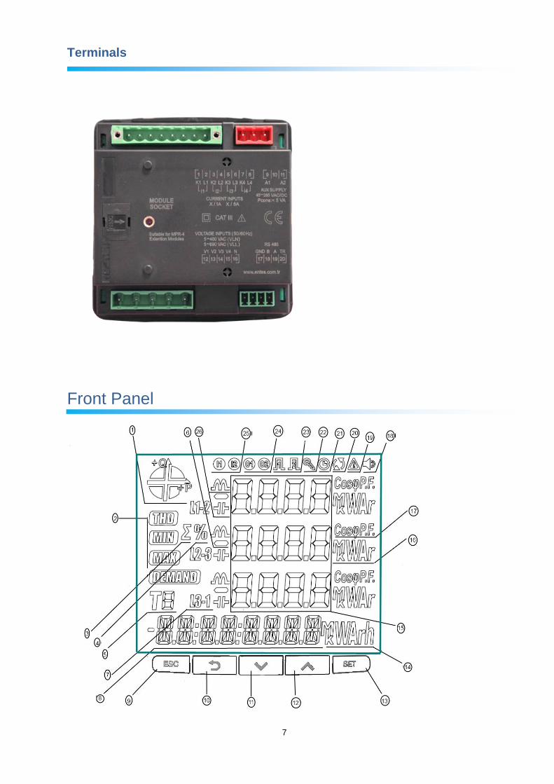
Terminals
Front Panel

8
1 – Indicates on which quadrant the network is operating. 2 – Indicates that the corresponding screen is one of THD, MIN, MAX or DEMAND screens. 3 – Indicates the total screen. (I.e. ΣTHD) 4 – Indicates the percent values. 5 – Indicates for which tariff the energy measurement is. 6 – Indicates negative value. 7 – Indicates L1, L2, L3 and L1-2, L2-3 and L3-1 measurements. 8 – Indicates energy value or time. 14 – Indicates the unit of the energy value 15 – Displays the measured values of the corresponding screen. 16 – Indicates the unit of the measured values. 17 – Indicates whether the value is CosØ or Power Factor. 18 – Indicates whether the alarm is active or not. 19 – Indicates a warning. 20 – Indicates a connection error. 21 – Indicates that the alarm clock is active. 22 – Indicates that the device is locked. 23 – Indicates which pulse output is active. 24 – Indicates which digital output is active. 25 – Indicates which digital input is active. 26 – Indicates whether the measurement is inductive or reactive.
Button Functions
In addition to their main functions, the 5 buttons on the front panel can be used as shortcut buttons for easily reaching screens.
ESC button (9): It has 3 main functions:
Exiting from any menu is done by pressing ESC button.
While on measuring screen: As seen on the symbols (V I F) above the button, it is used to browse between voltage, current and frequency measurement screens.
While on measuring screen: As seen on the symbols (Event) below the button, event screen is reached when pressed for 3 seconds.
BACK Button (10) : It has 3 main functions:
While on measuring screen: As seen on the symbols (P PF) above the button, it is used to browse between active power, reactive power, apparent power, power factor and Cos φ measurement screens.
It is used to select the previous digit while entering a numerical value in the menu or to browse back to a previous menu level.
While on measuring screen: As seen on the symbols (Test) below the button, connection control is reached when pressed for 3 seconds.
Down Button (11) : It has 2 main functions:
While on measuring screen: As seen on the symbols (E Clock) above the button, it is used to browse between import/export active energy consumption, reactive energy consumption, tariff and time information screens.
While on menu screens: It is used to browse between menu options and to decrease a value during adjustment.
9
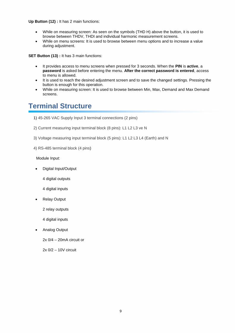
Up Button (12) : It has 2 main functions:
While on measuring screen: As seen on the symbols (THD H) above the button, it is used to browse between THDV, THDI and individual harmonic measurement screens.
While on menu screens: It is used to browse between menu options and to increase a value during adjustment.
SET Button (13) : It has 3 main functions:
It provides access to menu screens when pressed for 3 seconds. When the PIN is active, a password is asked before entering the menu. After the correct password is entered, access to menu is allowed.
It is used to reach the desired adjustment screen and to save the changed settings. Pressing the button is enough for this operation.
While on measuring screen: It is used to browse between Min, Max, Demand and Max Demand screens.
Terminal Structure
1) 45-265 VAC Supply Input 3 terminal connections (2 pins)
2) Current measuring input terminal block (8 pins): L1 L2 L3 ve N
3) Voltage measuring input terminal block (5 pins): L1 L2 L3 L4 (Earth) and N
4) RS-485 terminal block (4 pins)
Module Input:
Digital Input/Output
4 digital outputs
4 digital inputs
Relay Output
2 relay outputs
4 digital inputs
Analog Output
2x 0/4 – 20mA circuit or
2x 0/2 – 10V circuit
10
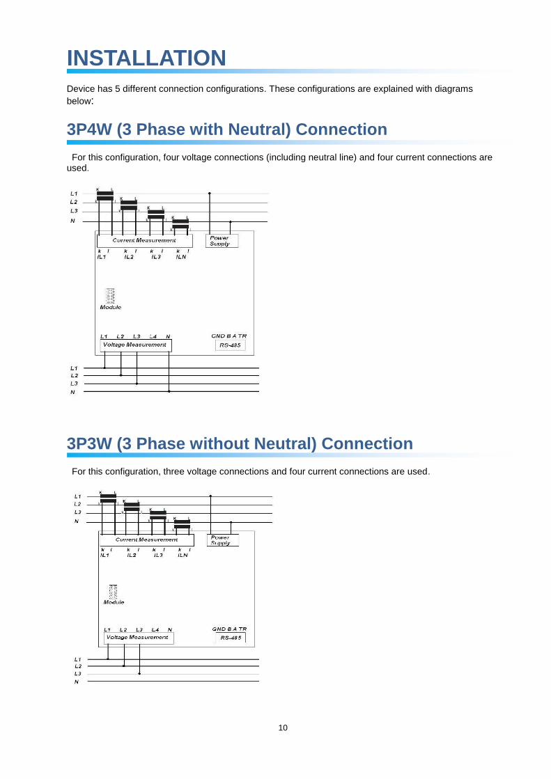
INSTALLATION
Device has 5 different connection configurations. These configurations are explained with diagrams
below:
3P4W (3 Phase with Neutral) Connection
For this configuration, four voltage connections (including neutral line) and four current connections are used.
3P3W (3 Phase without Neutral) Connection
For this configuration, three voltage connections and four current connections are used.

11
Aron without Neutral Connection
For this configuration, three voltage connections and two current connections are used.
3P4W BLN (3 Phase Balanced with Neutral) Connection
For this configuration, four voltage connections and one current connection is used.
The device shows the same current value, which is measured from the first phase, for the unconnected
phases.

12
3P3W BLN (3 Phase Balanced without Neutral) Connection
For this configuration, three voltage connections and one current connection is used.
The device shows the same current value, which is measured from the first phase, for the unconnected
phases.

13
Connection Test
After finishing device connections, you can check the connection that you’ve done by using the automatic test function.
When you press the BACK button for 3 seconds, it switches to test mode. During this mode, at least 20% of the nominal voltage must be applied to the voltage measuring inputs, at least 10% of the nominal current must be applied to the current measuring inputs and the angle difference between current and voltage inputs must be less than 30 degrees. These test conditions must be met.
During connection test, the device controls the connections and it can correct them internally or it can leave the physical correction to the user.
If there’s an error between voltage inputs, it can only be corrected by changing physical connections.
If you encounter Error 12, make sure that all connections are done and minimum current/voltage values are applied to the device.
On the following table, possible connection errors that may be encountered during connection test and their corresponding error codes that are displayed on the device screen.
Test Error Code Test Code Description
0 All connections are correct
1 Phase-1 current direction is reversed
2 Phase-2 current direction is reversed
3 Phase-3 current direction is reversed
4 Phase-1 and Phase-2 voltage connections are reversed
5 Phase-1 and Phase-3 voltage connections are reversed
6 Phase-2 and Phase-3 voltage connections are reversed
7 Voltage connection phase sequence will be changed as L1,L2,L3 - L3,L1,L2.
8 Voltage connection phase sequence will be changed as L3,L2,L1 - L3,L1,L2.
9 CT-1, CT-2 will be swapped.
10 CT-1, CT-3 will be swapped.
11 CT-2, CT-3 will be swapped.
12 Test conditions are not met.
Line Termination Resistor
Line termination resistors are used when communication line length is longer than 10 metres. Please short terminals GND and TR to enhance communication performance in case of multiple devices on the same network.

14
OPERATING INSTRUCTIONS
Measurement Screens
Measurement screens, which can be accessed by pressing the related buttons, are explained in this
section.
Current, Voltage and Frequency Screens
BUTTON NAME DISPLAYED MEASUREMENT SCREEN
ESC (VIF) VOLTAGE (L-N)
BUTTON NAME DISPLAYED MEASUREMENT SCREEN
ESC (VIF) VOLTAGE (L-L)
BUTTON NAME DISPLAYED MEASUREMENT SCREEN
ESC (VIF) CURRENT

15
BUTTON NAME DISPLAYED MEASUREMENT SCREEN
ESC (VIF) V- UNBALANCE
BUTTON NAME DISPLAYED MEASUREMENT SCREEN
ESC (VIF) I- UNBALANCE
BUTTON NAME DISPLAYED MEASUREMENT SCREEN
ESC (VIF) WORK HOUR COUNTER 1
BUTTON NAME DISPLAYED MEASUREMENT SCREEN
ESC (VIF) WORK HOUR COUNTER 2

16
Power and Power Factor Screens
BUTTON NAME DISPLAYED MEASUREMENT SCREEN
BACK (P PF) TOTAL POWER
BUTTON NAME DISPLAYED MEASUREMENT SCREEN
BACK (P PF) ACTIVE POWER
BUTTON NAME DISPLAYED MEASUREMENT SCREEN
BACK (P PF) REACTIVE POWER

17
BUTTON NAME DISPLAYED MEASUREMENT SCREEN
BACK (P PF) APPARENT POWER
BUTTON NAME DISPLAYED MEASUREMENT SCREEN
BACK (P PF) POWER FACTOR
BUTTON NAME DISPLAYED MEASUREMENT SCREEN
BACK (P PF) COS φ
18
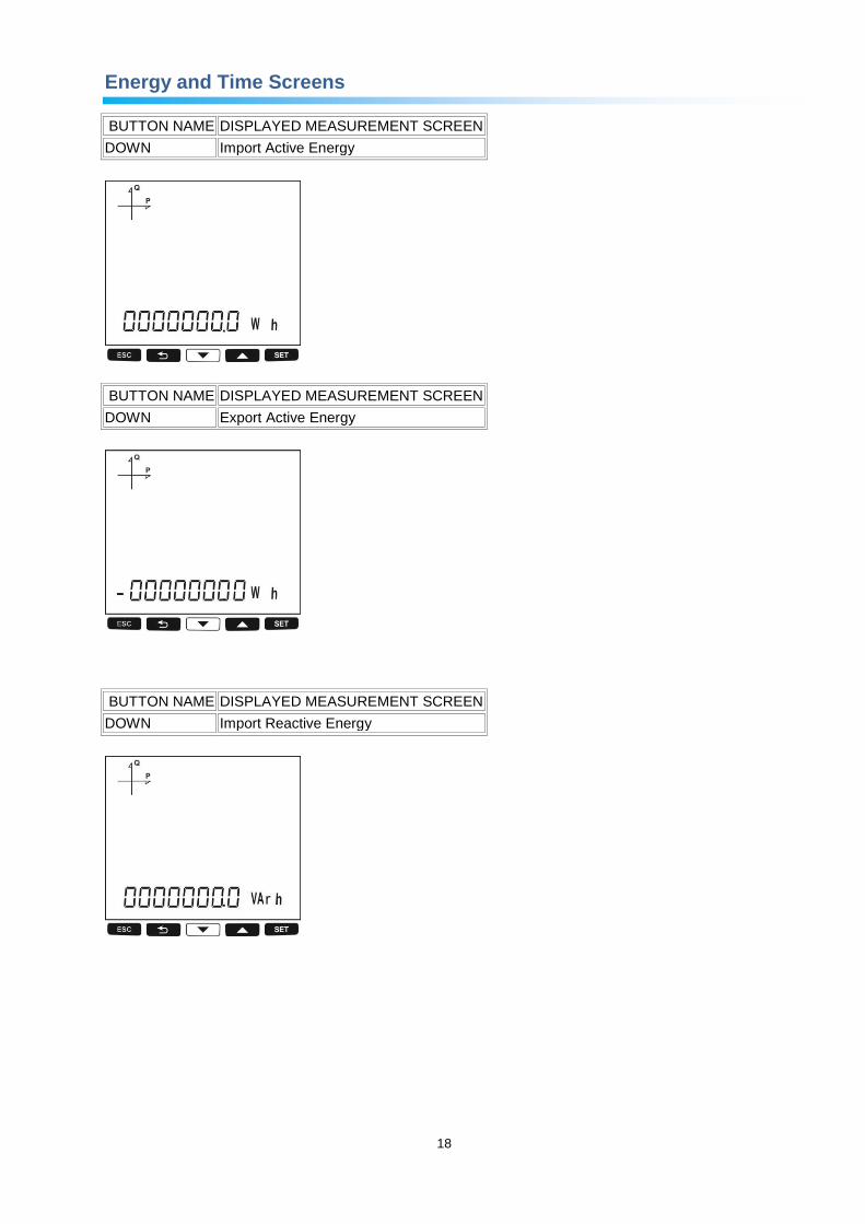
Energy and Time Screens
BUTTON NAME DISPLAYED MEASUREMENT SCREEN
DOWN Import Active Energy
BUTTON NAME DISPLAYED MEASUREMENT SCREEN
DOWN Export Active Energy
BUTTON NAME DISPLAYED MEASUREMENT SCREEN
DOWN Import Reactive Energy

19
BUTTON NAME DISPLAYED MEASUREMENT SCREEN
DOWN Export Reactive Energy
BUTTON NAME DISPLAYED MEASUREMENT SCREEN
DOWN Apparent Energy
BUTTON NAME DISPLAYED MEASUREMENT SCREEN
DOWN Active Energy in Total Tariff

20
BUTTON NAME DISPLAYED MEASUREMENT SCREEN
DOWN Active Energy in Active Tariff
BUTTON NAME DISPLAYED MEASUREMENT SCREEN
DOWN Energy Values for each Programmed Tariff (T1, T2, T3, T4, T5, T6, T7, T8, TG)
BUTTON NAME DISPLAYED MEASUREMENT SCREEN
DOWN Time

21
BUTTON NAME DISPLAYED MEASUREMENT SCREEN
DOWN Date
THD and Harmonics Screens
For models with THD, only current THD and voltage THD screens will be displayed. For models with harmonics, separate harmonics for current and voltage can be displayed also.
BUTTON NAME DISPLAYED MEASUREMENT SCREEN
UP THD V
BUTTON NAME DISPLAYED MEASUREMENT SCREEN
UP VOLTAGE HARMONICS (H01, H02, ..., H51 in order) (Only for MPR47S model)

22
Current screen is displayed when “V I F” button is pressed. When THD H button is pressed at this point, following screens are displayed.
BUTTON NAME DISPLAYED MEASUREMENT SCREEN
UP THD I
BUTTON NAME DISPLAYED MEASUREMENT SCREEN
UP CURRENT HARMONICS (H01, H02, ..., H51 in order) (Only for MPR47S model)
Minimum, Maximum and Demand Screens
To see the minimum and maximum values of current and voltage, first select the relevant screen with “V I F” button. Afterwards, you can display the following screens with MAX/MIN DEMAND button.
BUTTON NAME DISPLAYED MEASUREMENT SCREEN
SET MAX(Phase-Neutral Voltage)

23
BUTTON NAME DISPLAYED MEASUREMENT SCREEN
SET MIN(Phase-Neutral Voltage)
BUTTON NAME DISPLAYED MEASUREMENT SCREEN
SET MAX (Phase-Phase Voltage)
BUTTON NAME DISPLAYED MEASUREMENT SCREEN
SET MIN (Phase-Phase Voltage)
24
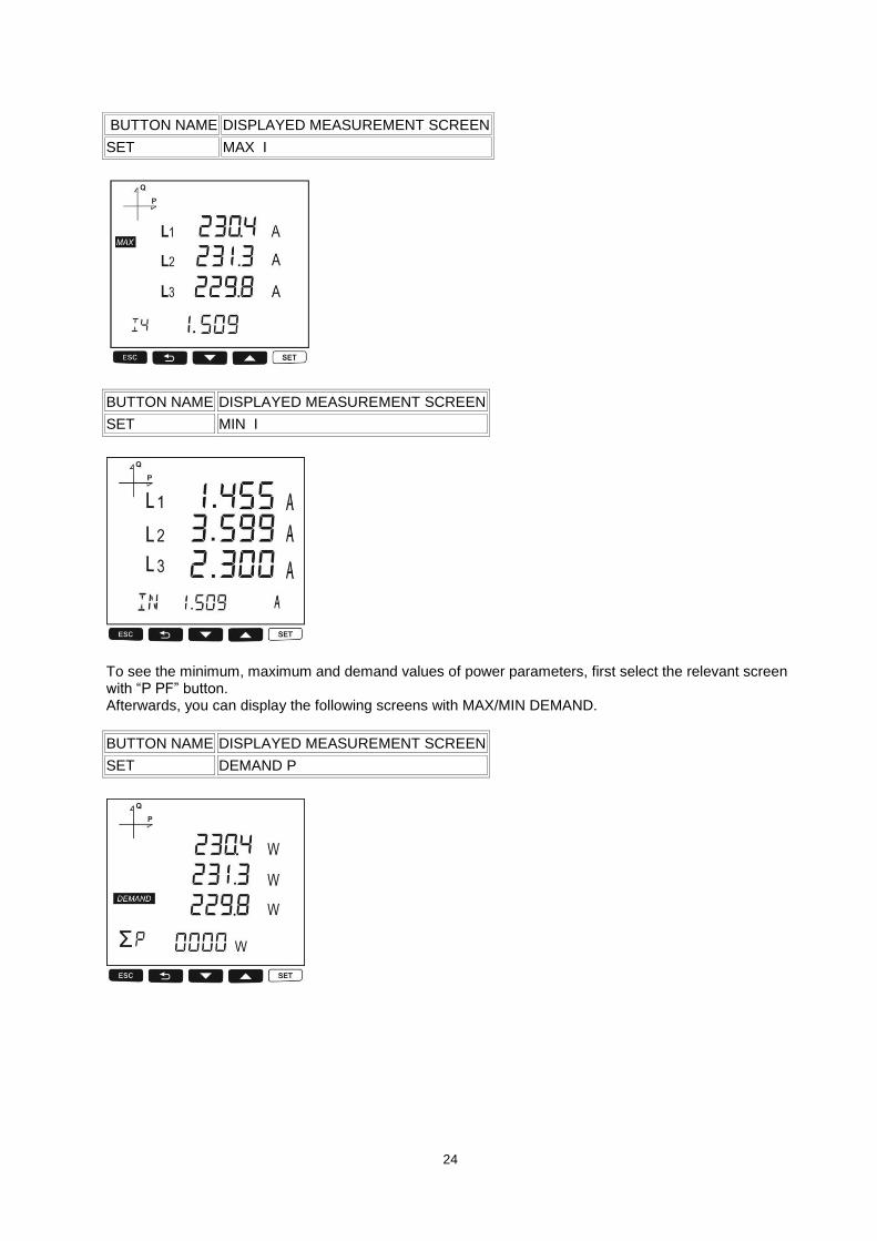
BUTTON NAME DISPLAYED MEASUREMENT SCREEN
SET MAX I
BUTTON NAME DISPLAYED MEASUREMENT SCREEN
SET MIN I
To see the minimum, maximum and demand values of power parameters, first select the relevant screen with “P PF” button. Afterwards, you can display the following screens with MAX/MIN DEMAND.
BUTTON NAME DISPLAYED MEASUREMENT SCREEN
SET DEMAND P

25
BUTTON NAME DISPLAYED MEASUREMENT SCREEN
SET MAX DEMAND P
BUTTON NAME DISPLAYED MEASUREMENT SCREEN
SET MAX P
BUTTON NAME DISPLAYED MEASUREMENT SCREEN
SET MIN P

26
BUTTON NAME DISPLAYED MEASUREMENT SCREEN
SET MAX Q
BUTTON NAME DISPLAYED MEASUREMENT SCREEN
SET MIN Q
BUTTON NAME DISPLAYED MEASUREMENT SCREEN
SET DEMAND S

27
BUTTON NAME DISPLAYED MEASUREMENT SCREEN
SET MAX DEMAND S
BUTTON NAME DISPLAYED MEASUREMENT SCREEN
SET MAX S
BUTTON NAME DISPLAYED MEASUREMENT SCREEN
SET MIN S

28
Setup Screen
Accessing the Programming Menu:
When the SET button of the device is pressed for 3 seconds with PIN feature activated, entry screen is displayed. When the password is entered correctly, programming menu is reached.
If PIN feature is not activated, programming menu is reached directly. Password for the device is 1234 as factory default.
Device Installation Settings
In order for the device to become operational, information of current and voltage transformers on the system and the connection type must be entered to the device. When the device is energized for the first time, it will require the user to enter this information. Adjust the following settings accordingly by using SET and UP/DOWN buttons.
Language Setting
Messages on the device screen can be viewed in four languages:
1. Turkish
2. English
3. German
4. French
After selecting your language with UP/DOWN buttons, Press the SET button and go to the next step.
Connection Type Setting
1. By using UP/DOWN buttons, select your network connection type as 3P4W, 3P3W, ARON, 3P4W Balanced or 3P3W Balanced.
2. For unbalanced systems, 3P4W or 3P3W should be selected. 3. Press the SET button and go to the next step.

29
Voltage Transformer Usage
1. By using UP/DOWN buttons, select Enable or Disable indicating whether you use a voltage transformer on your system.
2. Press the SET button and go to the next step.
VT Secondary Value
1. Enter the secondary value of your VT by using SET and UP/DOWN buttons. 2. You can approve a digit value by pressing the SET button. 3. After entering the necessary value, Press the SET button and go to the next step.
VT Primary Value
1. Enter the primary value of your VT by using SET and UP/DOWN buttons. 2. You can approve a digit value by pressing the SET button. 3. After entering the necessary value, Press the SET button and go to the next step.

30
CT Secondary Value Selection
1. By using UP/DOWN buttons, select your CT secondary value type as 1A or 5A. 2. After selecting the necessary value, Press the SET button and go to the next step.
CT Primary Value
1. Enter the primary value of your CT between 1 and 9999 A by using SET and UP/DOWN buttons. 2. You can approve a digit value by pressing the SET button. 3. After entering the necessary value, Press the SET button and go to the next step.
Nominal Frequency Value Selection
1. By using UP/DOWN buttons, select your nominal network frequency as 50 Hz or 60 Hz. 2. After selecting the necessary value, Press the SET button and go to the next step.

31
Nominal Operating Voltage Value
1. Enter the nominal operating voltage value between 25 and 300 V by using SET and UP/DOWN buttons.
2. You can approve a digit value by pressing the SET button. 3. After entering the necessary value, Press the SET button and go to the next step.
Time Zone Setting
1. By using UP/DOWN buttons, you can select the time zone information about the device location between -12:00 and +12:00 in 30 minute intervals.
2. After selecting the necessary value, Press the SET button and go to the next step.
Date Setting
1. Enter the date by using SET and UP/DOWN buttons. 2. You can approve a digit value by pressing the SET button. 3. After entering the correct date, Press the SET button and go to the next step.

32
Hour Setting
1. Enter the time by using SET and UP/DOWN buttons. 2. You can approve a digit value by pressing the SET button. 3. After entering the correct date, Press the SET button and go to the next step.
Display Settings
Language settings, display contrast and backlight settings are located under Display Settings section.
Language Setting
Messages on the device screen can be viewed in four languages:
1. Turkish 2. English 3. German 4. French
1. Select Language option under Settings/Display and press SET button. 2. Current language option will start blinking. Select one of the options above and press SET button. 3. When exiting from the menu with the BACK or ESC button, don’t forget to save the changes.
Backlight Setting

33
There are three settings for the backlight of the device:
1. Always ON, 2. Always OFF, 3. Automatic.
When “Automatic” option is selected, the backlight turns on after a button is pressed and turns off after no button is pressed for 3 minutes.
1. Select Backlight option under Settings/Display and press SET button. 2. Current backlight option will start blinking. Select one of the options above and press SET button. 3. When exiting from the menu with the BACK or ESC button, don’t forget to save the changes.
Display Contrast Setting
Display contrast of the device can be selected between 0 and 15.
The factory default value is 3.
1. Select Contrast option under Settings/Display and press SET button. 2. Current contrast option will start blinking. Select one of the options and press SET button. 3. When exiting from the menu with the BACK or ESC button, don’t forget to save the changes.
Time Settings
Hour Setting
The time of the device’s RTC module can be set in hours, minutes and seconds.
To set the time, follow these steps:
1. Press the SET button while on Setup Clock screen. 2. Press the SET button on the Hour Set screen, which is the first option. 3. While on Hour Set screen, Press the SET button and select the hour part. 4. Hour value will start to blink.

34
5. Adjust the hour by using UP/DOWN buttons. 6. Press the SET button to switch to the minute value. Repeat these steps for minutes and seconds
parts. 7. When exiting from the menu with the BACK or ESC button, don’t forget to save the changes.
Date Setting
The date of the device’s RTC module can be set in days, months and years.
To set the date, follow these steps:
1. Press the SET button on the Date Set screen. 2. Press the SET button. Adjust the day with UP/DOWN buttons. 3. Press the SET button. Adjust the month with UP/DOWN buttons. 4. Press the SET button. Adjust the year with UP/DOWN buttons. 5. When exiting from the menu with the BACK or ESC button, don’t forget to save the changes.
Time Zone Setting
1. Press the SET button while “Clock Time Zone” is displayed. 2. Selected Time Zone screen is displayed. 3. Enter the menu by pressing the SET button. 4. Select your time zone in 30 minutes increments by using UP/DOWN buttons. 5. Press the SET button after you’re finished with selection. 6. When exiting from the menu with the BACK or ESC button, don’t forget to save the changes.

35
DST Mode Setting
1. Press the SET button while Clock DST Mode screen is displayed. 2. Daylight Save screen is displayed. 3. Press the SET button and select one of EUROPE, USA, MANUEL and DISABLE options. 4. If you select MANUEL option; you will have to enter month, week, day and hour for the start of DST in
that order. 5. After finishing the DST Start settings; you will have to enter month, week, day and hour for the end of
DST in that order. 6. After selecting your DST setting, press the SET menu and exit from this menu. 7. When exiting from the menu with the BACK or ESC button, don’t forget to save the changes.
RS-485 Communication Settings
RS-485 Address Setting
1. Select Address option under Settings/RS-485 and press SET button. 2. Current address option will start blinking. You can browse between digits with SET and BACK
buttons. Select an address between 1 and 247 and press SET button. 3. When exiting from the menu with the BACK or ESC button, don’t forget to save the changes.
RS-485 Baudrate Setting
RS-485 communication speed of the device can be set to one of the following options:
1. 2400 baud 2. 4800 baud

36
3. 9600 baud 4. 19200 baud 5. 38400 baud 6. 57600 baud 7. 115200 baud
1. Press the SET button while on RS-485 baud rate screen. 2. Press the SET button to start selecting the baudrate value. 3. Select your communication speed by using UP/DOWN buttons. 4. When exiting from the menu with the BACK or ESC button, don’t forget to save the changes.
RS-485 Parity Setting
Communication parity of the device can be set as Odd, Even or None.
Factory default setting for parity is NONE.
1. Press the SET button while on RS-485 parity screen. 2. Press the SET button to start selecting the parity option. 3. Select your parity by using UP/DOWN buttons. 4. When exiting from the menu with the BACK or ESC button, don’t forget to save the changes.
Input Parameter Settings
When an Analog Input or Digital Input module is connected to the device, these menus become active. When these modules are connected, following settings can be changed.
The number of appearing menus depends on how many inputs are available on the connected module.
1. Digital Input: When this option is selected, the device detects the logic level on the input.
37
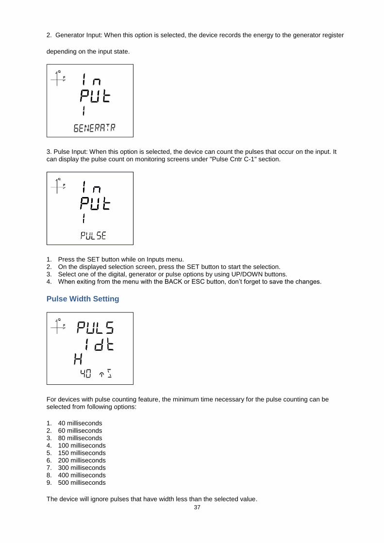
2. Generator Input: When this option is selected, the device records the energy to the generator register
depending on the input state.
3. Pulse Input: When this option is selected, the device can count the pulses that occur on the input. It can display the pulse count on monitoring screens under "Pulse Cntr C-1" section.
1. Press the SET button while on Inputs menu. 2. On the displayed selection screen, press the SET button to start the selection. 3. Select one of the digital, generator or pulse options by using UP/DOWN buttons. 4. When exiting from the menu with the BACK or ESC button, don’t forget to save the changes.
Pulse Width Setting
For devices with pulse counting feature, the minimum time necessary for the pulse counting can be selected from following options:
1. 40 milliseconds 2. 60 milliseconds 3. 80 milliseconds 4. 100 milliseconds 5. 150 milliseconds 6. 200 milliseconds 7. 300 milliseconds 8. 400 milliseconds 9. 500 milliseconds
The device will ignore pulses that have width less than the selected value.

38
Pulse input menu will be activated when pulse option is selected as the input parameter.
1. Press the SET button while on Pulse Inputs menu. 2. On the displayed selection screen, press the SET button to start the selection. 3. Select a pulse width by using UP/DOWN buttons. 4. When exiting from the menu with the BACK or ESC button, don’t forget to save the changes.
Output Parameter Settings
When an output or input/output module is connected to the device, the purpose of the output is selected from this menu. The number of appearing menus depends on how many outputs are available on the connected module. Digital output of the device can be used for one of the following applications:
1. Output as Pulse: When this option is selected, the device creates output pulses depending on selected value of active or reactive energy consumption.
2. Output as Alarm: When this option is selected, the output changes from logic-1 to logic-0 if the selected parameter exceeds or is below the limit value.
When the alarm condition is resolved, output returns to logic-1.
3. Output as Remote Control: When this option is selected, the user can change the output of the device from logic-1 to logic-0 remotely via RS-485 communication.
This option can be used to control a circuit remotely.

39
1. Press the SET button while on Outputs menu. 2. Select the relevant output number and press the SET button to start the selection. 3. Select an output operation type mentioned above by using UP/DOWN buttons. 4. When exiting from the menu with the BACK or ESC button, don’t forget to save the changes.
Recording Settings
The following parameters can be recorded to the internal memory of the device in adjustable time intervals. Afterwards, the recorded values can be remotely viewed:
1. Load Profile
2. Voltages
3. Currents
4. Powers
5. THD values
Selecting Parameter to Be Recorded
The parameter to be recorded to the internal memory is selected as following:
Load Profile Settings
1. Press the SET button while Log Setup-Load Profile is displayed. 2. Current option is displayed. Press the SET button again. 3. Select Active or Passive with UP/DOWN buttons. Press the SET button. 4. If you select Active option, recording time interval selection will be active. 5. Select you recording time interval in seconds with UP/DOWN buttons. 6. Finish the selection by pressing the SET button. 7. When exiting from the menu with the BACK or ESC button, don’t forget to save the changes.

40
Voltage Settings
1. Press the SET button while Log Setup-Voltages is displayed. 2. Current option is displayed. Press the SET button again. 3. Select Active or Passive with UP/DOWN buttons. Press the SET button. 4. If you select Active option, recording time interval selection will be active. 5. Select you recording time interval in seconds with UP/DOWN buttons. 6. Finish the selection by pressing the SET button. 7. When exiting from the menu with the BACK or ESC button, don’t forget to save the changes.
Current Settings
1. Press the SET button while Log Setup-Currents is displayed. 2. Current option is displayed. Press the SET button again. 3. Select Active or Passive with UP/DOWN buttons. Press the SET button. 4. If you select Active option, recording time interval selection will be active. 5. Select you recording time interval in seconds with UP/DOWN buttons. 6. Finish the selection by pressing the SET button. 7. When exiting from the menu with the BACK or ESC button, don’t forget to save the changes.
Power Settings
1. Press the SET button while Log Setup-Powers is displayed. 2. Current option is displayed. Press the SET button again. 3. Select Active or Passive with UP/DOWN buttons. Press the SET button. 4. If you select Active option, recording time interval selection will be active.
41
5. Select you recording time interval in seconds with UP/DOWN buttons. 6. Finish the selection by pressing the SET button. 7. When exiting from the menu with the BACK or ESC button, don’t forget to save the changes.
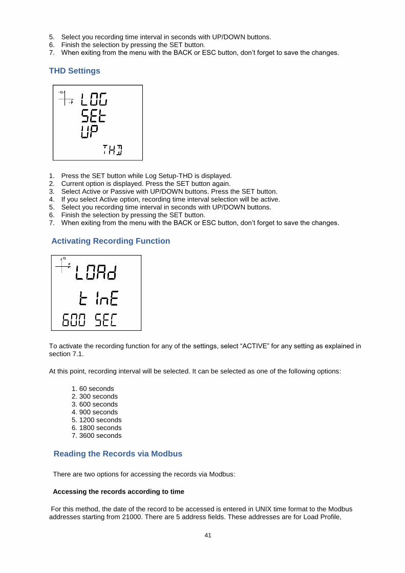
THD Settings
1. Press the SET button while Log Setup-THD is displayed. 2. Current option is displayed. Press the SET button again. 3. Select Active or Passive with UP/DOWN buttons. Press the SET button. 4. If you select Active option, recording time interval selection will be active. 5. Select you recording time interval in seconds with UP/DOWN buttons. 6. Finish the selection by pressing the SET button. 7. When exiting from the menu with the BACK or ESC button, don’t forget to save the changes.
Activating Recording Function
To activate the recording function for any of the settings, select “ACTIVE” for any setting as explained in section 7.1.
At this point, recording interval will be selected. It can be selected as one of the following options:
1. 60 seconds 2. 300 seconds 3. 600 seconds 4. 900 seconds 5. 1200 seconds 6. 1800 seconds 7. 3600 seconds
Reading the Records via Modbus
There are two options for accessing the records via Modbus:
Accessing the records according to time
For this method, the date of the record to be accessed is entered in UNIX time format to the Modbus addresses starting from 21000. There are 5 address fields. These addresses are for Load Profile,
42
Voltage, Current, Power and THD in that order. The device finds the record closest to the entered date and writes the index belonging to this record to the related index registers.
When the user writes this index to the index register at the bottom of the tables at register addresses 23000, 24000, 25000 etc., the details of the entered register will be accessible on the same tables.
A free software is available to read the log values that are stored on the device. It can be downloaded from the following link:
http://www.entes.com.tr/dosyalar/Applications/Mpr3x4xLogReader/publish.htm
Accessing the records according to index
For this method, the user writes the record index number to the index register at the bottom of the tables at register addresses 23000, 24000, 25000 etc., the details of the entered register will be accessible on the same tables.
Pulse Input Settings
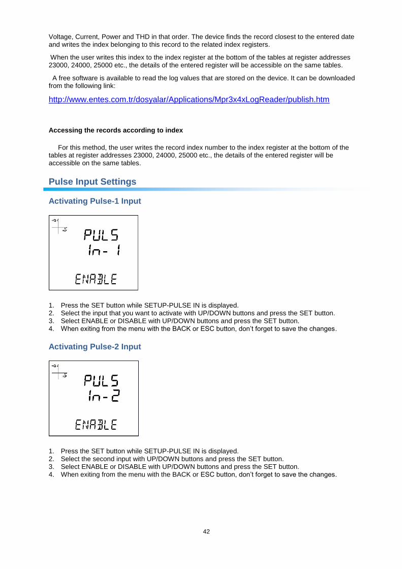
Activating Pulse-1 Input
1. Press the SET button while SETUP-PULSE IN is displayed. 2. Select the input that you want to activate with UP/DOWN buttons and press the SET button. 3. Select ENABLE or DISABLE with UP/DOWN buttons and press the SET button. 4. When exiting from the menu with the BACK or ESC button, don’t forget to save the changes.
Activating Pulse-2 Input
1. Press the SET button while SETUP-PULSE IN is displayed. 2. Select the second input with UP/DOWN buttons and press the SET button. 3. Select ENABLE or DISABLE with UP/DOWN buttons and press the SET button. 4. When exiting from the menu with the BACK or ESC button, don’t forget to save the changes.

43
Selecting Pulse-1 Ratio
1. Press UP button while PULSE IN-1 Enable is displayed. 2. This value indicates for how many incoming pulses the device will increase the pulse counter. Select
this value as displayed above. 3. Exit from the menu when selection is complete. 4. When exiting from the menu with the BACK or ESC button, don’t forget to save the changes.
Selecting Pulse-2 Ratio
1. Press UP button while PULSE IN-2 Enable is displayed. 2. This value indicates for how many incoming pulses the device will increase the pulse counter. Select
this value as displayed above. 3. Exit from the menu when selection is complete. 4. When exiting from the menu with the BACK or ESC button, don’t forget to save the changes.
Pulse Output Settings
Pulse Output According to Active Energy
1. Press UP button while OUTPUT 1 PULSE is displayed. 2. Select the energy value for which the device will create pulse signals. 3. Exit from the menu when selection is complete. 4. When exiting from the menu with the BACK or ESC button, don’t forget to save the changes.
44
When Pulse Output is selected, the device can create pulses for import or export active energy according to the increments listed below. Import or export energy can be selected as the source.
1. 1 Wh 2. 10 Wh 3. 100 Wh 4. 1 kWh 5. 10 kWh 6. 100 kWh 7. 1 MWh.
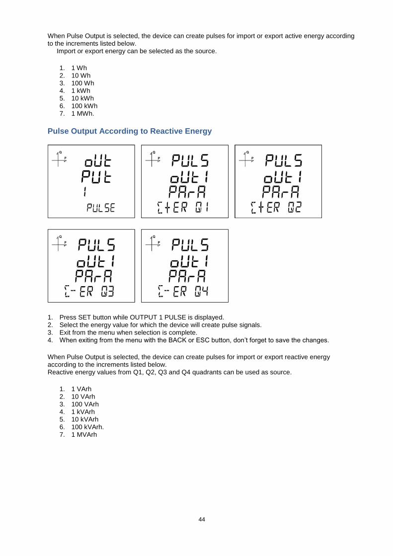
Pulse Output According to Reactive Energy
1. Press SET button while OUTPUT 1 PULSE is displayed. 2. Select the energy value for which the device will create pulse signals. 3. Exit from the menu when selection is complete. 4. When exiting from the menu with the BACK or ESC button, don’t forget to save the changes.
When Pulse Output is selected, the device can create pulses for import or export reactive energy according to the increments listed below. Reactive energy values from Q1, Q2, Q3 and Q4 quadrants can be used as source.
1. 1 VArh 2. 10 VArh 3. 100 VArh 4. 1 kVArh 5. 10 kVArh 6. 100 kVArh. 7. 1 MVArh

45
Pulse Output Duration Setting
The duration during the pulse stays at logic-1 level is entered here.
1. Press SET button while PULS DURATION is displayed. 2. Enter the duration in seconds with 0.01 second increments with UP/DOWN buttons. 3. Exit from the menu when selection is complete. 4. When exiting from the menu with the BACK or ESC button, don’t forget to save the changes.
Pulse Output Inactive Time Setting
The duration during the pulse stays at logic-0 level is entered here.
1. Press SET button while PULSE DUTY is displayed. 2. Enter the inactive time in seconds with 0.01 second increments with UP/DOWN buttons. 3. Exit from the menu when selection is complete. 4. When exiting from the menu with the BACK or ESC button, don’t forget to save the changes.
Operating Hours Settings
The device can count the time when a selected parameter exceeds or falls below an adjusted limit value. This feature is explained in this section.
Parameter is selected under Hour Counter menu. If you select VLN for example, display changes as following.

46
1. Press SET button while HOUR COUN PARA is displayed. 2. Select the parameter with UP/DOWN buttons. 3. Press the SET button.
Afterwards, the limit value is selected. When the parameter exceeds this limit value, hour counter will start.
1. Press SET button while HOUR COUN LEVL is displayed. 2. Enter a limit value by using UP/DOWN buttons. You can select different digits with SET or BACK
buttons. 3. Exit from the menu when selection is complete. 4. When exiting from the menu with the BACK or ESC button, don’t forget to save the changes.
Alarm Settings
Different parameters can be assigned to the 4 alarms that the device has.
Following operations are described for a single alarm but they are the same for the other 3 alarms.
Activating Alarm
Alarm is activated by following these steps:
1. Press the SET button while Setup Alarm is displayed. 2. While Alarm Enable is displayed, Press the SET button and select ENABLE or DISABLE with
UP/DOWN buttons. 3. Press the SET button after completing your selection.

47
4. When exiting from the menu with the BACK or ESC button, don’t forget to save the changes.
Alarm Parameter Selection
Alarm parameter is selected by following these steps:
1. Press the SET button while Alarm Setup is displayed. 2. Find Alarm Parameter by pressing UP/DOWN buttons. 3. Enter Alarm Parameter menu by pressing the SET button. 4. Select one of the following parameters with UP/DOWN buttons:
a. Phase currents b. Total Current c. Current Demand d. Total Current Demand e. Active Power f. Reactive Power g. Apparent Power h. Total Active Power i. Total Reactive Power j. Total Apparent Power k. Active Power Demand l. Apparent Power Demand m. Total Active Power Demand n. Total Apparent Power Demand o. Cos phi p. Total Cos phi q. Frequency r. THDV s. THDU t. THDI u. Hour Counter v. Digital Input w. Tariffs x. Phase-Neutral Voltage y. Phase-Phase Voltage
5. Press the SET button after completing your selection. You can start selecting the Alarm Operation Type by pressing the UP button.

48
Alarm Operation Type Selection
1. While AL-1 OPE RAND is displayed, press the SET button to select the alarm operation type. 2. Select one of the following options by using UP/DOWN buttons:
a. In window b. Out window c. Lower than d. Higher than
3. When “In window” or “Out window” options are selected, high and low limit values are entered. 4. When “Higher than” option is selected, a high limit value is entered. When “Lower than” option is
selected, a low limit value is entered. 5. Press SET button to approve your selection. 6. When exiting from the menu with the BACK or ESC button, don’t forget to save the changes.
High Alarm Limit Setting
A high limit for the alarm is entered in this menu.
1. While Alarm Enable is selected, find Alarm High menu with UP/DOWN buttons. 2. Press the SET button. Enter the high alarm limit with UP/DOWN buttons. 3. Press the SET button after completing your selection. 4. Alarm parameters can be saved for 4 different alarms separately. 5. When exiting from the menu with the BACK or ESC button, don’t forget to save the changes.

49
Low Alarm Limit Setting
A low limit for the alarm is entered in this menu.
1. While Alarm Enable is selected, find Alarm Low menu with UP/DOWN buttons. 2. Press the SET button. Enter the low alarm limit with UP/DOWN buttons. 3. Press the SET button after completing your selection. 4. Alarm parameters can be saved for 4 different alarms separately. 5. When exiting from the menu with the BACK or ESC button, don’t forget to save the changes.
Alarm Hysteresis Setting
A hysteresis value for the alarm is entered in this menu.
1. While Alarm Enable is selected, find Alarm Hyst menu with UP/DOWN buttons. 2. Press the SET button. Enter the hysteresis value for the alarm as % with UP/DOWN buttons. 3. Press the SET button after completing your selection. 4. Alarm parameters can be saved for 4 different alarms separately. 5. When exiting from the menu with the BACK button, don’t forget to save the changes.
Alarm Delay Times Setting
1. After entering a hysteresis value, press the UP button to find the Alarm On Delay menu. 2. Press the SET button. Enter the alarm ON delay value in seconds for the alarm UP/DOWN buttons.
Go to the next digit with SET button. When the alarm conditions occur on the system, the alarm will be activated after the entered time passes.
3. Press the SET button after completing your entering.
50
4. Find oFF dELY menu with UP/DOWN buttons to enter an Alarm Off Delay value. 5. Press the SET button. Enter the alarm OFF delay value in seconds for the alarm UP/DOWN buttons.
Go to the next digit with SET button. When the alarm conditions are cleared on the system, the alarm will be deactivated after the entered time passes
6. When exiting from the menu with the BACK or ESC button, don’t forget to save the changes.
Tariff Settings
Activating Tariffs
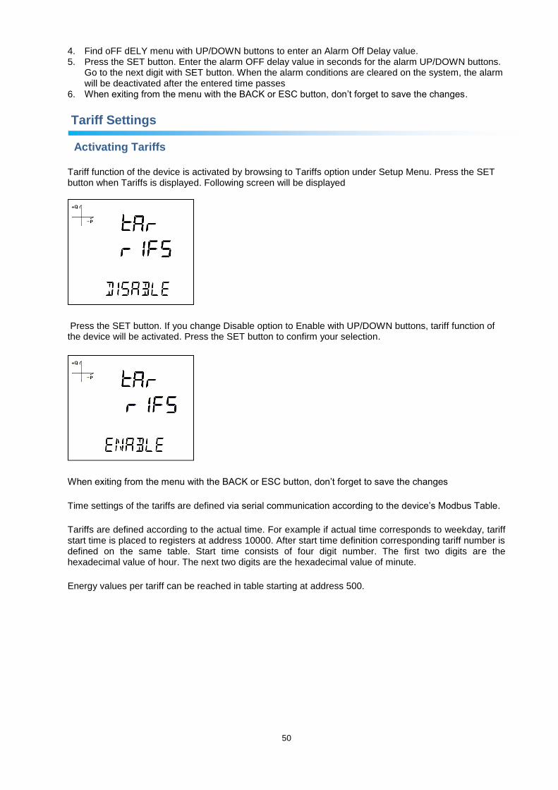
Tariff function of the device is activated by browsing to Tariffs option under Setup Menu. Press the SET button when Tariffs is displayed. Following screen will be displayed
Press the SET button. If you change Disable option to Enable with UP/DOWN buttons, tariff function of the device will be activated. Press the SET button to confirm your selection.
When exiting from the menu with the BACK or ESC button, don’t forget to save the changes
Time settings of the tariffs are defined via serial communication according to the device’s Modbus Table.
Tariffs are defined according to the actual time. For example if actual time corresponds to weekday, tariff start time is placed to registers at address 10000. After start time definition corresponding tariff number is defined on the same table. Start time consists of four digit number. The first two digits are the hexadecimal value of hour. The next two digits are the hexadecimal value of minute.
Energy values per tariff can be reached in table starting at address 500.

51
Reset Settings
Users can reset the minimum, maximum, demand and log records that the device has stored.
Resetting Maximum Values
1. Select Maximum under Reset menu and press the SET button. 2. Press the SET button while "Reset High" is displayed and select YES option with UP/DOWN buttons. 3. Press the SET button. 4. When exiting from the menu with the BACK or ESC button, don’t forget to save the changes.
Resetting Minimum Values
1. Select Minimum under Reset menu and press the SET button. 2. Press the SET button while "Reset Low" is displayed and select YES option with UP/DOWN buttons. 3. Press the SET button. 4. When exiting from the menu with the BACK or ESC button, don’t forget to save the changes.
Resetting Demand Values
1. Select Demand under Reset menu and press the SET button. 2. Press the SET button while "Reset High d" is displayed and select YES option with UP/DOWN
buttons. 3. Press the SET button.

52
4. When exiting from the menu with the BACK or ESC button, don’t forget to save the changes.
Resetting Maximum Demand Values
1. Select Max Demand under Reset menu and press the SET button. 2. Press the SET button while "Reset de" is displayed and select YES option with UP/DOWN buttons. 3. Press the SET button. 4. When exiting from the menu with the BACK or ESC button, don’t forget to save the changes.
Resetting Energy Values
1. Select Energy under Reset menu and press the SET button. 2. Press the SET button while "Reset Energ" is displayed and select YES option with UP/DOWN
buttons. 3. Press the SET button. 4. When exiting from the menu with the BACK or ESC button, don’t forget to save the changes.
Resetting Generator Energy Values
1. Select Gen Energy under Reset menu and press the SET button. 2. Press the SET button while "Reset GenE" is displayed and select YES option with UP/DOWN
buttons. 3. Press the SET button. 4. When exiting from the menu with the BACK or ESC button, don’t forget to save the changes.
53
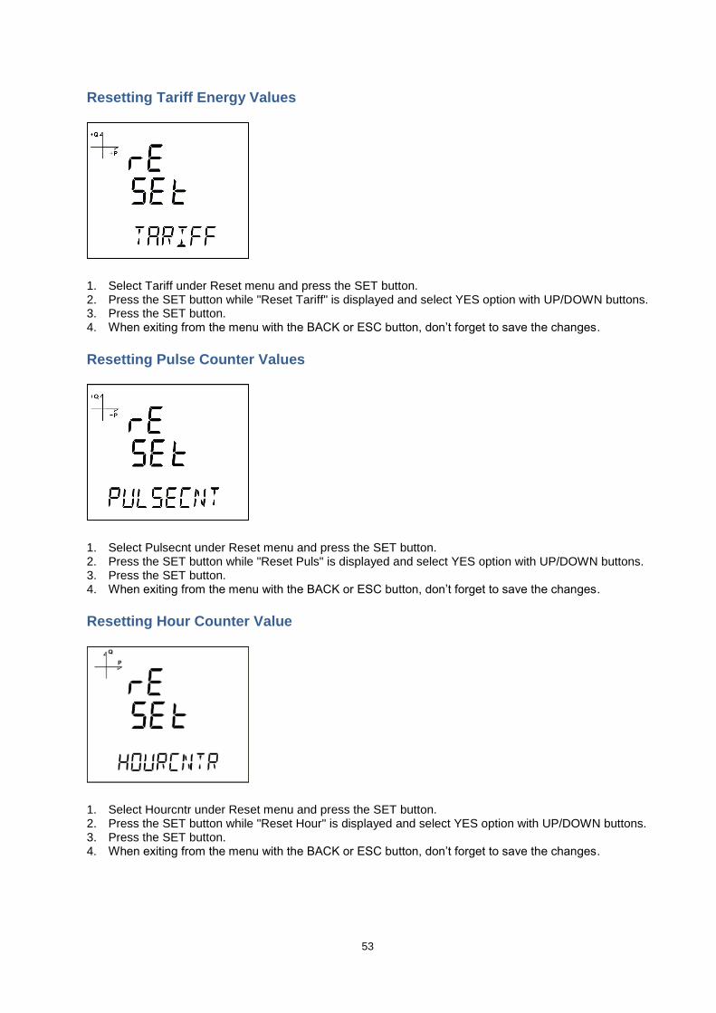
Resetting Tariff Energy Values
1. Select Tariff under Reset menu and press the SET button. 2. Press the SET button while "Reset Tariff" is displayed and select YES option with UP/DOWN buttons. 3. Press the SET button. 4. When exiting from the menu with the BACK or ESC button, don’t forget to save the changes.
Resetting Pulse Counter Values
1. Select Pulsecnt under Reset menu and press the SET button. 2. Press the SET button while "Reset Puls" is displayed and select YES option with UP/DOWN buttons. 3. Press the SET button. 4. When exiting from the menu with the BACK or ESC button, don’t forget to save the changes.
Resetting Hour Counter Value
1. Select Hourcntr under Reset menu and press the SET button. 2. Press the SET button while "Reset Hour" is displayed and select YES option with UP/DOWN buttons. 3. Press the SET button. 4. When exiting from the menu with the BACK or ESC button, don’t forget to save the changes.

54
Resetting Log Values
1. Select Logs under Reset menu and press the SET button. 2. Press the SET button while "Reset Logs" is displayed and select YES option with UP/DOWN buttons. 3. Press the SET button. 4. When exiting from the menu with the BACK or ESC button, don’t forget to save the changes.
System Settings
Pin Code Activation
Preventing access to settings menu with a password can be accomplished from this menu.
1. Find "Pin Act" option under System Menu. Press the SET button. 2. When you press the SET button while "Pin Acivate" is displayed, you will have to enter the 4 digit
factory default pin (mentioned below). 3. Select the default pin digits with UP/DOWN buttons and confirm the digit with SET button. 4. After entering the correct default pin, you can change Disable option to Enable. Press the SET button
after selecting Enable. 5. When exiting from the menu with the BACK or ESC button, don’t forget to save the changes.
Factory default pin is 1234.
Changing the Pin Code
55
1. Find "Pin Chng" option under System Menu. Press the SET button. 2. While "Pin CHAnGE" is displayed, press the SET button. 3. Enter the old pin digit by digit with UP/DOWN buttons. 4. If you enter the old pin incorrectly, "ERROR" will be displayed. 5. If “ERROR” is displayed, press the SET button and enter the pin again correctly. 6. If you enter the old pin correctly, "Pin CHnGnE" will be displayed. 7. Enter your new 4 digit pin and press the SET button. 8. Enter your new 4 digit pin again and press the SET button. 9. After entering the new pin correctly twice, "Pin CHAnGE CHANGED" will be displayed. 10. When exiting from the menu with the BACK or ESC button, don’t forget to save the changes. You can
use your new pin next time you enter the Setup Menu.
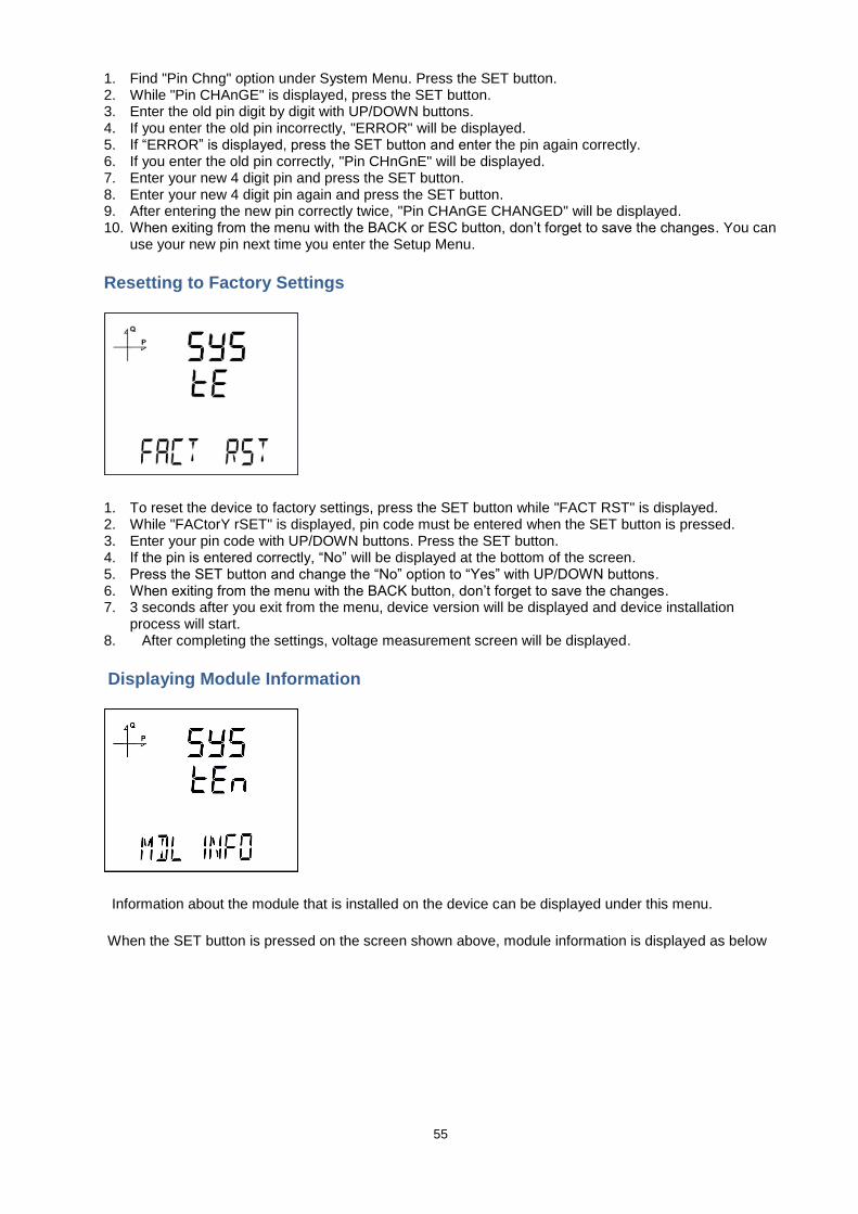
Resetting to Factory Settings
1. To reset the device to factory settings, press the SET button while "FACT RST" is displayed. 2. While "FACtorY rSET" is displayed, pin code must be entered when the SET button is pressed. 3. Enter your pin code with UP/DOWN buttons. Press the SET button. 4. If the pin is entered correctly, “No” will be displayed at the bottom of the screen. 5. Press the SET button and change the “No” option to “Yes” with UP/DOWN buttons. 6. When exiting from the menu with the BACK button, don’t forget to save the changes. 7. 3 seconds after you exit from the menu, device version will be displayed and device installation
process will start. 8. After completing the settings, voltage measurement screen will be displayed.
Displaying Module Information
Information about the module that is installed on the device can be displayed under this menu.
When the SET button is pressed on the screen shown above, module information is displayed as below

56
Displaying Software and Hardware Version
The device’s hardware and software version can be displayed under this menu:
1. Press the SET button while "Soft VER" is displayed under System menu. 2. Software version of the device will be displayed on the bottom of the screen. 3. When you press the UP button here, hardware version of the device will be displayed under "HArd
VerSIon".
Displaying Serial Number of the Device
1. Press the SET button while "Serial N" is displayed under System menu. 2. 8 digit serial number of the device will be displayed under "SErIAL no".

57
Analog Output Settings
When an analog output module is connected to the device, the purpose of the output is selected from this menu.
Analog Output-1 Type Settings
1. Press the SET button while Analog O-1 Type is displayed. 2. Select one of 0-5V, 0-10V, -5 ~ 5V and -10 ~ 10V options with UP/DOWN buttons. 3. After completing your selection, press the SET button. 4. When exiting from the menu with the BACK or ESC button, don’t forget to save the changes.
Analog Output-1 Parameter Settings
1. Press the SET button while Analog O-1 Para is displayed. 2. Select one of the following parameters with UP/DOWN buttons.
VLN1, VLN2, VLN3, VLN4, VLL1, VLL2, VLL3, IL1, IL2, IL3, IL4, IN, IL1 DEMAND, IL2 DEMAND, IL3 DEMAND, IL4 DEMAND, IN DEMAND, P1, P2, P3, Q1, Q2, Q3, S1, S2, S3, Total P, Total Q, Total S, Cos Phi-1, Cos Phi-2, Cos Phi-3, Total Cos Phi, Frequency, VLN4, IL4, Total I, Total I Demand, Total P Demand, Total S Demand, Total VLN, Total VLL.
3. After completing your selection, press the SET button. 4. When exiting from the menu with the BACK or ESC button, don’t forget to save the changes.

58
Analog Output-1 High Value Settings
1. Press the SET button while Analog O-1 High is displayed. 2. Enter your high value with UP/DOWN buttons. 3. After entering your value, press the SET button. 4. When exiting from the menu with the BACK or ESC button, don’t forget to save the changes.
Analog Output-1 Low Value Settings
1. Press the SET button while Analog O-1 Low is displayed. 2. Enter your low value with UP/DOWN buttons. 3. After entering your value, press the SET button. 4. When exiting from the menu with the BACK or ESC button, don’t forget to save the changes.
For example;
Set the following options from the devices settings menu.
Type: 0-20 mA
Para (Parameter): VLN1
Low (Low Value): 90 V
High (High Value): 300 V
According to the settings above, analog output will be 0 mA when VL1 value is 90 V or lower and it will be 20 mA when VL1 value is 300 V or larger.
When VL1 value is 200 V, the output value is calculated as below:

59
Analog Output-2 Type Settings
1. Press the SET button while Analog O-2 Type is displayed. 2. Select one of 0-5V, 0-10V, -5 ~ 5V and -10 ~ 10V options with UP/DOWN buttons. 3. After completing your selection, press the SET button. 4. When exiting from the menu with the BACK or ESC button, don’t forget to save the changes.
Analog Output-2 Parameter Settings
1. Press the SET button while Analog O-2 Para is displayed. 2. Select one of the following parameters with UP/DOWN buttons.
VLN1, VLN2, VLN3, VLN4, VLL1, VLL2, VLL3, IL1, IL2, IL3, IL4, IN, IL1 DEMAND, IL2 DEMAND, IL3 DEMAND, IL4 DEMAND, IN DEMAND, P1, P2, P3, Q1, Q2, Q3, S1, S2, S3, Total P, Total Q, Total S, Cos Phi-1, Cos Phi-2, Cos Phi-3, Total Cos Phi, Frequency, VLN4, IL4, Total I, Total I Demand, Total P Demand, Total S Demand, Total VLN, Total VLL.
3. After completing your selection, press the SET button. 4. When exiting from the menu with the BACK or ESC button, don’t forget to save the changes.
Analog Output-2 High Value Settings
1. Press the SET button while Analog O-2 High is displayed. 2. Enter your high value with UP/DOWN buttons. 3. After entering your value, press the SET button. 4. When exiting from the menu with the BACK or ESC button, don’t forget to save the changes.

60
Analog Output-2 Low Value Settings
1. Press the SET button while Analog O-2 Low is displayed. 2. Enter your low value with UP/DOWN buttons. 3. After entering your value, press the SET button. 4. When exiting from the menu with the BACK or ESC button, don’t forget to save the changes.
Reporting Screen
When the ESC button of the device is pressed for 3 seconds, recorded event details can be browsed.
The device can record 255 events.
Recorded event types: First commission, short interruption (<3 s), long interruption, alarm, settings change, time change and value reset.
Different records can be viewed with UP/DOWN buttons.
Events are listed according to their occurrence times.
First event is the newest that has occurred, last event is the oldest one that has occurred.
After pressing the SET button, details of the event can be displayed in the following order;
1. Start date, 2. Start time,

61
3. End date, 4. End time, 5. Duration, 6. Parameter, 7. Source of the event (if the event type is alarm), 8. Value that caused the event (if the event type is alarm).
If no button is pressed for 60 seconds, the device returns to measuring screen.

62
TECHNICAL FEATURES AND APPENDIX
Technical Features
Operating Voltage (Un) 45 – 265 VAC/DC
Operating Frequency (f) 45-65 Hz
Supply Input Burden <5 VA
Supply Input Burden <1 VA
Measuring Voltage Input (Vin) 10 – 300 VAC (L-N) 10 – 690 VAC (L-L)
Measuring Current Input (Iin) 0.05 – 5.5A ~
Measuring Power Range 0...9999 MW
Measuring Energy Range 9999999.9 k/M (Wh, VArh)
Class
Voltage 0.5%
Current 0.5%
Frequency 0.1%
cosφ ±0.2%
Active Power 1%
Reactive Power 1%
Active Power Energy 1%
Reactive Power Energy 2%
Current Transformer Ratio (Ctr) 1...5000
Voltage Transformer Ratio (Vtr) 1MV / measurement
Demand Time Adjustable between 1-60 minutes
Communication (Isolated) MODBUS RTU (RS-485)
Baud Rate 2400 – 115200 bps
Address 1 – 247
Parity None, Even, Odd
Stop Bit 1
Max Communication Distance 1200 m (MODBUS/RS-485 side, with signal amplifier)
Internal Memory 16MB
Relay Outputs (2 pcs, with module) 2 NO, 5 A, 1250 VA
Pulse Outputs (4 pcs, with module) Modular
Pulse Width t-ON = ≥ 30 ms
Time between two pulse peaks t-OFF = ≥ 30 ms
Transition Time t-T = ≤ 5 ms
Digital Inputs (4 pcs, with module) 12...48 VAC/DC
Analog Voltage Output (2 pcs, with module) 0 – 10 V, ±5 V, ±10 V
Analog Current Output (2 pcs, with module) 0/4 – 20mA, 4-24 mA
Connection Type 3P4W, 3P3W, ARON, 3P4W balances, 3P3W balanced
Harmonics Measurement (For MPR-47S) 2nd – 51st Harmonics
Operating Temperature -5...+55ºC
Storage Temperature -20…+70ºC
Humidity Maximum 90%
Display Backlit FSTN Custom LCD
Data Logging Available
Real Time Clock Available
Tariffs 8+1 (Generator)
Dimensions 96x96x50 mm
Device Protection Class Double Insulation
Front Panel Protection Class IP51
Terminals Protection Class IP20
Enclosure Material Nonflammable
Installation Front Panel Mounting
Cable Thickness For Voltage Connection Max. 2.5 mm2

63
Cable Thickness For Current Connection Max. 2.5 mm2
Cable Thickness For RS-485 Connection CAT 5 Cable
Weight 0.335 kg/pcs

64
Measurement Menu Map 1

65
Measurement Menu Map 2