Embed Size (px)
Citation preview

MPLS: Layer 3 VPNs Configuration Guide, Cisco IOS Release 15M&TFirst Published: 2012-11-21
Last Modified: 2013-03-15
Americas HeadquartersCisco Systems, Inc.170 West Tasman DriveSan Jose, CA 95134-1706USAhttp://www.cisco.comTel: 408 526-4000
800 553-NETS (6387)Fax: 408 527-0883

THE SPECIFICATIONS AND INFORMATION REGARDING THE PRODUCTS IN THIS MANUAL ARE SUBJECT TO CHANGE WITHOUT NOTICE. ALL STATEMENTS,INFORMATION, AND RECOMMENDATIONS IN THIS MANUAL ARE BELIEVED TO BE ACCURATE BUT ARE PRESENTED WITHOUT WARRANTY OF ANY KIND,EXPRESS OR IMPLIED. USERS MUST TAKE FULL RESPONSIBILITY FOR THEIR APPLICATION OF ANY PRODUCTS.
THE SOFTWARE LICENSE AND LIMITED WARRANTY FOR THE ACCOMPANYING PRODUCT ARE SET FORTH IN THE INFORMATION PACKET THAT SHIPPED WITHTHE PRODUCT AND ARE INCORPORATED HEREIN BY THIS REFERENCE. IF YOU ARE UNABLE TO LOCATE THE SOFTWARE LICENSE OR LIMITED WARRANTY,CONTACT YOUR CISCO REPRESENTATIVE FOR A COPY.
The Cisco implementation of TCP header compression is an adaptation of a program developed by the University of California, Berkeley (UCB) as part of UCB's public domain version ofthe UNIX operating system. All rights reserved. Copyright © 1981, Regents of the University of California.
NOTWITHSTANDING ANY OTHERWARRANTY HEREIN, ALL DOCUMENT FILES AND SOFTWARE OF THESE SUPPLIERS ARE PROVIDED “AS IS" WITH ALL FAULTS.CISCO AND THE ABOVE-NAMED SUPPLIERS DISCLAIM ALL WARRANTIES, EXPRESSED OR IMPLIED, INCLUDING, WITHOUT LIMITATION, THOSE OFMERCHANTABILITY, FITNESS FOR A PARTICULAR PURPOSE AND NONINFRINGEMENT OR ARISING FROM A COURSE OF DEALING, USAGE, OR TRADE PRACTICE.
IN NO EVENT SHALL CISCO OR ITS SUPPLIERS BE LIABLE FOR ANY INDIRECT, SPECIAL, CONSEQUENTIAL, OR INCIDENTAL DAMAGES, INCLUDING, WITHOUTLIMITATION, LOST PROFITS OR LOSS OR DAMAGE TO DATA ARISING OUT OF THE USE OR INABILITY TO USE THIS MANUAL, EVEN IF CISCO OR ITS SUPPLIERSHAVE BEEN ADVISED OF THE POSSIBILITY OF SUCH DAMAGES.
Any Internet Protocol (IP) addresses and phone numbers used in this document are not intended to be actual addresses and phone numbers. Any examples, command display output, networktopology diagrams, and other figures included in the document are shown for illustrative purposes only. Any use of actual IP addresses or phone numbers in illustrative content is unintentionaland coincidental.
All printed copies and duplicate soft copies of this document are considered uncontrolled. See the current online version for the latest version.
Cisco has more than 200 offices worldwide. Addresses and phone numbers are listed on the Cisco website at www.cisco.com/go/offices.
Cisco and the Cisco logo are trademarks or registered trademarks of Cisco and/or its affiliates in the U.S. and other countries. To view a list of Cisco trademarks, go to this URL: www.cisco.comgo trademarks. Third-party trademarks mentioned are the property of their respective owners. The use of the word partner does not imply a partnership relationship between Cisco and anyother company. (1721R)
© 2012–2013 Cisco Systems, Inc. All rights reserved.
C O N T E N T S
MPLS Virtual Private Networks 1C H A P T E R 1
Finding Feature Information 1
Prerequisites for MPLS Virtual Private Networks 1
Restrictions for MPLS Virtual Private Networks 2
Information About MPLS Virtual Private Networks 4
MPLS Virtual Private Network Definition 4
How an MPLS Virtual Private Network Works 5
How Virtual Routing and Forwarding Tables Work in an MPLS Virtual Private Network 5
How VPN Routing Information Is Distributed in an MPLS Virtual Private Network 6
MPLS Forwarding 6
Major Components of an MPLS Virtual Private Network 6
Benefits of an MPLS Virtual Private Network 7
How to Configure MPLS Virtual Private Networks 9
Configuring the Core Network 9
Assessing the Needs of MPLS Virtual Private Network Customers 9
Configuring MPLS in the Core 10
Connecting the MPLS Virtual Private Network Customers 10
Defining VRFs on the PE Devices to Enable Customer Connectivity 10
Configuring VRF Interfaces on PE Devices for Each VPN Customer 11
Configuring Routing Protocols Between the PE and CE Devices 12
Verifying the Virtual Private Network Configuration 16
Verifying Connectivity Between MPLS Virtual Private Network Sites 16
Verifying IP Connectivity from CE Device to CE Device Across the MPLS Core 16
Verifying That the Local and Remote CE Devices Are in the PE Routing Table 17
Configuration Examples for MPLS Virtual Private Networks 18
Example: Configuring an MPLS Virtual Private Network Using RIP 18
MPLS: Layer 3 VPNs Configuration Guide, Cisco IOS Release 15M&Tiii
Example: Configuring an MPLS Virtual Private Network Using Static Routes 20
Additional References 21
Feature Information for MPLS Virtual Private Networks 21
Multiprotocol BGP MPLS VPN 23C H A P T E R 2
Finding Feature Information 23
Prerequisites for Multiprotocol BGP MPLS VPN 23
Information About Multiprotocol BGP MPLS VPN 24
MPLS Virtual Private Network Definition 24
How an MPLS Virtual Private Network Works 25
How Virtual Routing and Forwarding Tables Work in an MPLS Virtual Private Network 25
How VPN Routing Information Is Distributed in an MPLS Virtual Private Network 26
MPLS Forwarding 26
BGP Distribution of VPN Routing Information 26
Major Components of an MPLS Virtual Private Network 27
How to Configure Multiprotocol BGP MPLS VPN 27
Configuring Multiprotocol BGP Connectivity on the PE Devices and Route Reflectors 27
Troubleshooting Tips 29
Configuring BGP as the Routing Protocol Between the PE and CE Devices 29
Verifying the Virtual Private Network Configuration 31
Verifying Connectivity Between MPLS Virtual Private Network Sites 31
Verifying IP Connectivity from CE Device to CE Device Across the MPLS Core 32
Verifying That the Local and Remote CE Devices Are in the PE Routing Table 32
Configuration Examples for Multiprotocol BGP MPLS VPN 34
Example: Configuring an MPLS Virtual Private Network Using BGP 34
Additional References 35
Feature Information for Multiprotocol BGP MPLS VPN 35
MPLS VPN OSPF PE and CE Support 37C H A P T E R 3
Finding Feature Information 37
Prerequisites for MPLS VPN OSPF PE and CE Support 37
Information About MPLS VPN OSPF PE and CE Support 38
Overview of MPLS VPN OSPF PE and CE Support 38
How to Configure MPLS VPN OSPF PE and CE Support 38
MPLS: Layer 3 VPNs Configuration Guide, Cisco IOS Release 15M&Tiv
Contents

Configuring OSPF as the Routing Protocol Between the PE and CE Devices 38
Verifying Connectivity Between MPLS Virtual Private Network Sites 40
Verifying IP Connectivity from CE Device to CE Device Across the MPLS Core 40
Verifying That the Local and Remote CE Devices Are in the PE Routing Table 41
Configuration Examples for MPLS VPN OSPF PE and CE Support 42
Example: Configuring an MPLS VPN Using OSPF 42
Additional References 43
Feature Information for MPLS VPN OSPF PE and CE Support 43
MPLS VPN Support for EIGRP Between PE and CE 45C H A P T E R 4
Finding Feature Information 45
Prerequisites for MPLS VPN Support for EIGRP Between PE and CE 45
Information About MPLS VPN Support for EIGRP Between PE and CE 46
Overview of MPLS VPN Support for EIGRP Between PE and CE 46
How to Configure MPLS VPN Support for EIGRP Between PE and CE 46
Configuring EIGRP as the Routing Protocol Between the PE and CE Devices 46
Configuring EIGRP Redistribution in the MPLS VPN 48
Verifying Connectivity Between MPLS Virtual Private Network Sites 50
Verifying IP Connectivity from CE Device to CE Device Across the MPLS Core 50
Verifying That the Local and Remote CE Devices Are in the PE Routing Table 51
Configuration Examples for MPLS VPN Support for EIGRP Between PE and CE 52
Example: Configuring an MPLS VPN Using EIGRP 52
Additional References 54
Feature Information for MPLS VPN Support for EIGRP Between PE and CE 54
IPv6 VPN over MPLS 57C H A P T E R 5
Finding Feature Information 57
Prerequisites for IPv6 VPN over MPLS 57
Restrictions for IPv6 VPN over MPLS 58
Information About IPv6 VPN over MPLS 58
IPv6 VPN over MPLS Overview 58
Addressing Considerations for IPv6 VPN over MPLS 58
Basic IPv6 VPN over MPLS Functionality 59
IPv6 VPN Architecture Overview 59
MPLS: Layer 3 VPNs Configuration Guide, Cisco IOS Release 15M&Tv
Contents

IPv6 VPN Next Hop 60
MPLS Forwarding 60
VRF Concepts 60
IPv6 VPN Scalability 61
Advanced IPv6 MPLS VPN Functionality 62
Internet Access 62
Multiautonomous-System Backbones 63
Carrier Supporting Carriers 64
How to Configure IPv6 VPN over MPLS 64
Configuring a Virtual Routing and Forwarding Instance for IPv6 64
Binding a VRF to an Interface 66
Configuring a Static Route for PE-to-CE Routing 67
Configuring eBGP PE-to-CE Routing Sessions 68
Configuring the IPv6 VPN Address Family for iBGP 69
Configuring Route Reflectors for Improved Scalability 70
Configuring Internet Access 77
Configuring the Internet Gateway 77
Configuring the IPv6 VPN PE 81
Configuring a Multiautonomous-System Backbone for IPv6 VPN 84
Configuring the PE VPN for a Multiautonomous-System Backbone 86
Configuring the Route Reflector for a Multiautonomous-System Backbone 88
Configuring the ASBR 96
Configuring CSC for IPv6 VPN 99
Configuration Examples for IPv6 VPN over MPLS 101
Examples: IPv6 VPN over MPLS Routing 101
Example: BGP IPv6 Activity Summary 101
Example: Dumping the BGP IPv6 Tables 101
Example: Dumping the IPv6 Routing Tables 101
Examples: IPv6 VPN over MPLS Forwarding 102
Example: PE-CE Connectivity 102
Examples: PE Imposition Path 103
Examples: PE Disposition Path 104
Examples: Label Switch Path 105
Examples: IPv6 VPN over MPLS VRF 105
MPLS: Layer 3 VPNs Configuration Guide, Cisco IOS Release 15M&Tvi
Contents
Examples: VRF Information 105
Example: IPv6 VPN Configuration Using IPv4 Next Hop 106
Additional References 107
Glossary 107
Configuring Route Maps to Control the Distribution of MPLS Labels Between Routers in an MPLSVPN 109
C H A P T E R 6
Finding Feature Information 109
Restrictions for Using Route Maps with MPLS VPNs 109
Prerequisites for Using Route Maps with MPLS VPNs 110
Information About Route Maps in MPLS VPNs 110
How to Configure Route Maps in an MPLS VPN 110
Configuring a Route Map for Incoming Routes 110
Configuring a Route Map for Outgoing Routes 112
Applying the Route Maps to the MPLS VPN Edge Routers 114
Troubleshooting Tips 116
Configuration Examples for Route Maps in MPLS VPNs 116
Using a Route Map in an MPLS VPN Inter-AS Network Example 116
Using a Route Map in an MPLS VPN CSC Network Example 118
Additional References 118
Feature Information for Route Maps in MPLS VPNs 120
Assigning an ID Number to an MPLS VPN 121C H A P T E R 7
Finding Feature Information 121
Restrictions for MPLS VPN ID 121
Information About MPLS VPN ID 122
Introduction to MPLS VPN ID 122
Components of the MPLS VPN ID 122
Management Applications That Use MPLS VPN IDs 122
Dynamic Host Configuration Protocol 123
Remote Authentication Dial-In User Service 123
How to Configure an MPLS VPN ID 123
Specifying an MPLS VPN ID 123
Verifying the MPLS VPN ID Configuration 124
MPLS: Layer 3 VPNs Configuration Guide, Cisco IOS Release 15M&Tvii
Contents

Configuration Examples for Assigning an ID Number to an MPLS VPN 126
Example: Specifying an MPLS VPN ID 126
Example: Verifying the MPLS VPN ID Configuration 126
Additional References 126
Feature Information for MPLS VPN ID 127
MPLS VPN Show Running VRF 129C H A P T E R 8
Finding Feature Information 129
Prerequisites for MPLS VPN Show Running VRF 129
Restrictions for MPLS VPN Show Running VRF 130
Information About MPLS VPN Show Running VRF 130
Configuration Elements Displayed for MPLS VPN Show Running VRF 130
Display of VRF Routing Protocol Configuration 130
Display of Configuration Not Directly Linked to a VRF 131
Additional References 132
Feature Information for MPLS VPN Show Running VRF 132
Glossary 133
MPLS VPN Half-Duplex VRF 135C H A P T E R 9
Finding Feature Information 135
Prerequisites for MPLS VPN Half-Duplex VRF 135
Restrictions for MPLS VPN Half-Duplex VRF 136
Information About MPLS VPN Half-Duplex VRF 136
MPLS VPN Half-Duplex VRF Overview 136
Upstream and Downstream VRFs 137
Reverse Path Forwarding Check 137
How to Configure MPLS VPN Half-Duplex VRF 138
Configuring the Upstream and Downstream VRFs on the Spoke PE Device 138
Associating a VRF with an Interface 139
Configuring the Downstream VRF for an AAA Server 141
Verifying the MPLS VPN Half-Duplex VRF Configuration 141
Configuration Examples for MPLS VPN Half-Duplex VRF 144
Examples: Configuring the Upstream and Downstream VRFs on the Spoke PE Device 144
Example: Associating a VRF with an Interface 145
MPLS: Layer 3 VPNs Configuration Guide, Cisco IOS Release 15M&Tviii
Contents

Example Configuring MPLS VPN Half-Duplex VRF Using Static CE-PE Routing 145
Example: Configuring MPLS VPN Half-Duplex VRF Using RADIUS Server and Static CE-PERouting 146
Example: Configuring MPLS VPN Half-Duplex VRF Using Dynamic CE-PE Routing 148
Additional References 149
Feature Information for MPLS VPN Half-Duplex VRF 150
MPLS VPN VRF CLI for IPv4 and IPv6 VPNs 153C H A P T E R 1 0
Finding Feature Information 153
Prerequisites for MPLS VPN VRF CLI for IPv4 and IPv6 VPNs 153
Restrictions for MPLS VPN VRF CLI for IPv4 and IPv6 VPNs 154
Information About MPLS VPN VRF CLI for IPv4 and IPv6 VPNs 154
VRF Concepts Similar for IPv4 and IPv6 MPLS VPNs 154
Single-Protocol VRF to Multiprotocol VRF Migration 154
Multiprotocol VRF Configuration Characteristics 155
How to Configure MPLS VPN VRF CLI for IPv4 and IPv6 VPNs 156
Configuring a VRF for IPv4 and IPv6 MPLS VPNs 156
Associating a Multiprotocol VRF with an Interface 159
Verifying the MPLS VPN VRF CLI for IPv4 and IPv6 VPNs Configuration 160
Migrating from a Single-Protocol IPv4-Only VRF to a Multiprotocol VRF Configuration 163
Configuration Examples for MPLS VPN VRF CLI for IPv4 and IPv6 VPNs 165
Example: Multiprotocol VRF Configuration Single Protocol with Noncommon Policies 165
Example: Multiprotocol VRF Configuration Multiprotocol with Noncommon Policies 165
Example: Multiprotocol VRF Configuration Multiprotocol with Common Policies 166
Example:Multiprotocol VRFConfigurationMultiprotocol with Common andNoncommon Policies166
Examples: Configuring a VRF for IPv4 and IPv6 VPNs 166
Example: Associating a Multiprotocol VRF with an Interface 167
Examples: Migrating from a Single-Protocol IPv4-Only VRF Configuration to a Multiprotocol VRFConfiguration 167
Additional References 169
Feature Information for MPLS VPN VRF CLI for IPv4 and IPv6 VPNs 169
Glossary 170
MPLS: Layer 3 VPNs Configuration Guide, Cisco IOS Release 15M&Tix
Contents

MPLS VPN Route Target Rewrite 173C H A P T E R 1 1
Finding Feature Information 173
Prerequisites for MPLS VPN Route Target Rewrite 173
Restrictions for MPLS VPN Route Target Rewrite 174
Information About MPLS VPN Route Target Rewrite 174
Route Target Replacement Policy 174
Route Maps and Route Target Replacement 176
How to Configure MPLS VPN Route Target Rewrite 176
Configuring a Route Target Replacement Policy 176
Applying the Route Target Replacement Policy 180
Associating Route Maps with Specific BGP Neighbors 180
Refreshing BGP Session to Apply Route Target Replacement Policy 182
Troubleshooting Tips 183
Verifying the Route Target Replacement Policy 183
Troubleshooting Your Route Target Replacement Policy 185
Configuration Examples for MPLS VPN Route Target Rewrite 187
Examples: Configuring Route Target Replacement Policies 187
Examples: Applying Route Target Replacement Policies 188
Examples: Associating Route Maps with Specific BGP Neighbor 188
Example: Refreshing the BGP Session to Apply the Route Target Replacement Policy 189
Additional References 189
Feature Information for MPLS VPN Route Target Rewrite 189
Glossary 191
MPLS VPN Per VRF Label 193C H A P T E R 1 2
Finding Feature Information 193
Prerequisites for MPLS VPN Per VRF Label 193
Restrictions for MPLS VPN Per VRF Label 194
Information About MPLS VPN Per VRF Label 194
MPLS VPN Per VRF Label Functionality 194
How to Configure MPLS VPN Per VRF Label 195
Configuring the Per VRF Label Feature 195
Examples 196
MPLS: Layer 3 VPNs Configuration Guide, Cisco IOS Release 15M&Tx
Contents

Configuration Examples for MPLS VPN Per VRF Label 197
Example: No Label Mode Default Configuration 197
Example: Mixed Mode with Global Per-Prefix 199
Example: Mixed Mode with Global Per-VRF 200
Additional References 202
Feature Information for MPLS VPN Per VRF Label 202
MPLS VPN SNMP Notifications 205C H A P T E R 1 3
Finding Feature Information 205
Prerequisites for MPLS VPN SNMP Notifications 206
Restrictions for MPLS VPN SNMP Notifications 206
Information About MPLS VPN SNMP Notifications 206
Cisco Implementation of MPLS VPN MIB 206
Capabilities Supported by MPLS VPN SNMP Notifications 207
Notification Generation Events for the MPLS VPN MIB 207
Notification Specification for MPLS-VPN-MIB 208
Monitoring the MPLS VPN SNMP Notifications 209
How to Configure the MPLS VPN SNMP Notifications 209
Configuring an SNMP Community 209
Configuring the Device to Send SNMP Traps 211
Configuring Threshold Values for MPLS VPN SNMP Notifications 213
Configuration Examples for MPLS VPN SNMP Notifications 214
Example: Configuring the Community 214
Example: Configuring the Device to Send SNMP Traps 215
Example: Configuring Threshold Values for MPLS VPN SNMP Notifications 215
Additional References 215
Feature Information for MPLS VPN SNMP Notifications 216
Glossary 217
Multi-VRF Selection Using Policy-Based Routing 221C H A P T E R 1 4
Finding Feature Information 221
Prerequisites for Multi-VRF Selection Using Policy-Based Routing 222
Restrictions for Multi-VRF Selection Using Policy-Based Routing 222
Information About Multi-VRF Selection Using Policy-Based Routing 223
MPLS: Layer 3 VPNs Configuration Guide, Cisco IOS Release 15M&Txi
Contents

Policy Routing of VPN Traffic Based on Match Criteria 223
Policy-Based Routing set Commands 223
Policy-routing Packets for VRF Instances 223
Change of Normal Routing and Forwarding Behavior 224
Support of Inherit-VRF Inter-VRF and VRF-to-Global Routing 225
How to Configure Multi-VRF Selection Using Policy-Based Routing 226
Defining the Match Criteria for Multi-VRF Selection Using Policy-Based Routing 226
Configuring Multi-VRF Selection Using Policy-Based Routing with a Standard Access List 226
Configuring Multi-VRF Selection Using Policy-Based Routing with a Named Extended AccessList 227
Configuring Multi-VRF Selection in a Route Map 228
ConfiguringMulti-VRF SelectionUsing Policy-Based Routing and IPVRFReceive on the Interface230
Verifying the Configuration of Multi-VRF Selection Using Policy-Based Routing 231
Configuration Examples for Multi-VRF Selection Using Policy-Based Routing 234
Example: Defining the Match Criteria for Multi-VRF Selection Using Policy-Based Routing 234
Example: Configuring Multi-VRF Selection in a Route Map 234
Additional References 235
Feature Information for Multi-VRF Selection Using Policy-Based Routing 235
Glossary 236
MPLS VPN VRF Selection Based on a Source IP Address 239C H A P T E R 1 5
Finding Feature Information 239
Prerequisites for MPLS VPN VRF Selection Based on a Source IP Address 240
Restrictions for MPLS VPN VRF Selection Based on a Source IP Address 241
Information About MPLS VPN VRF Selection Based on a Source IP Address 241
VRF Selection Process 241
VRF Selection Examples 242
VRF Selection is a Unidirectional Feature 243
Conditions Under Which VRF Selection Becomes Bidirectional 244
Advantages of VRF Selection over Per-Interface IP VPN Configuration 244
Benefits of MPLS VPN VRF Selection Based on a Source IP Address 245
How to Configure MPLS VPN VRF Selection Based on a Source IP Address 246
Configuring VRF Selection 246
MPLS: Layer 3 VPNs Configuration Guide, Cisco IOS Release 15M&Txii
Contents

Establishing IP Static Routes for a VRF Instance 247
Verifying VRF Selection 248
Troubleshooting Tips 248
Configuration Examples for MPLS VPN VRF Selection Based on a Source IP Address 249
Example: Enabling MPLS VPNs 249
Example: Creating a VRF Routing Table 249
Example: Defining VRF Selection Entries 249
Example: Defining IP Static Routes for a VRF 250
Example: Configuring an Interface for VRF Selection 250
Example: Configuring a BGP Device for VRF Selection 250
Example: Configuring a VRF to Eliminate Unnecessary Packet Forwarding 251
Additional References 251
Feature Information for MPLS VPN VRF Selection Based on a Source IP Address 251
MPLS VPN VRF Selection Using Policy-Based Routing 253C H A P T E R 1 6
Finding Feature Information 253
Prerequisites for MPLS VPN VRF Selection Using Policy-Based Routing 253
Restrictions for MPLS VPN VRF Selection Using Policy-Based Routing 254
Information About MPLS VPN VRF Selection Using Policy-Based Routing 254
Introduction to MPLS VPN VRF Selection Using Policy-Based Routing 254
Policy-Based Routing Set Clauses Overview 255
Match Criteria for Policy-Based Routing VRF Selection Based on Packet Length 255
How to Configure MPLS VPN VRF Selection Using Policy-Based Routing 255
Configuring Policy-Based Routing VRF Selection with a Standard Access List 255
Configuring Policy-Based Routing VRF Selection with a Named Access List 256
Configuring Policy-Based Routing VRF Selection in a Route Map 257
Configuring Policy-Based Routing on the Interface 259
Configuring IP VRF Receive on the Interface 260
Verifying the Configuration of the MPLS VPN VRF Selection Using Policy-Based Routing 261
Configuration Examples for MPLS VPN VRF Selection Using Policy-Based Routing 262
Example: Defining Policy-Based Routing VRF Selection in an Access List 262
Examples: Verifying VRF Selection Using Policy-Based Routing 263
Example: Verifying Match Criteria 263
Example: Verifying Route-Map Configuration 263
MPLS: Layer 3 VPNs Configuration Guide, Cisco IOS Release 15M&Txiii
Contents

Example: Verifying Policy-Based Routing VRF Selection Policy 263
Additional References 264
Feature Information for MPLS VPN VRF Selection Using Policy-Based Routing 264
MPLS VPN BGP Local Convergence 267C H A P T E R 1 7
Finding Feature Information 267
Prerequisites for MPLS VPN BGP Local Convergence 267
Restrictions for MPLS VPN BGP Local Convergence 268
Information About MPLS VPN BGP Local Convergence 269
How Link Failures Are Handled with BGP 269
How Links Are Handled with the MPLS VPN BGP Local Convergence Feature 269
How Link Failures Are Detected 270
How to Configure MPLS VPN BGP Local Convergence 271
Configuring MPLS VPN BGP Local Convergence with IPv4 271
Configuring MPLS VPNBGP Local Convergence with IPv6 272
Examples 274
Troubleshooting Tips 274
Configuration Examples for MPLS VPN BGP Local Convergence 274
Examples: MPLS VPN BGP Local Convergence 274
Examples: MPLS VPN BGP Local Convergence for 6VPE 6PE 277
Additional References 281
Feature Information for MPLS VPN BGP Local Convergence 282
Multi-VRF Support 285C H A P T E R 1 8
Finding Feature Information 285
Prerequisites for Multi-VRF Support 285
Restrictions for Multi-VRF Support 285
Information About Multi-VRF Support 286
How the Multi-VRF Support Feature Works 286
How Packets Are Forwarded in a Network Using the Multi-VRF Support Feature 287
Considerations When Configuring the Multi-VRF Support Feature 288
How to Configure Multi-VRF Support 288
Configuring VRFs 288
Configuring BGP as the Routing Protocol 290
MPLS: Layer 3 VPNs Configuration Guide, Cisco IOS Release 15M&Txiv
Contents

Configuring PE-to-CE MPLS Forwarding and Signaling with BGP 292
Configuring a Routing Protocol Other than BGP 294
Configuring PE-to-CE MPLS Forwarding and Signaling with LDP 295
Configuration Examples for Multi-VRF Support 296
Example: Configuring Multi-VRF Support on the PE Device 296
Example: Configuring Multi-VRF Support on the CE Device 296
Additional References 298
Feature Information for Multi-VRF Support 298
MPLS VPN per Customer Edge (CE) Label 299C H A P T E R 1 9
Finding Feature Information 299
Prerequisites for MPLS VPN per CE Label 299
Restrictions for MPLS VPN per CE Label 300
Information About MPLS VPN per CE Label 300
MPLS VPN per CE Label Functionality 300
How to Configure MPLS VPN per CE Label 301
Configuring the per CE Label Feature 301
Configuration Examples for MPLS VPN per CE Label 302
Examples: MPLS VPN per CE Label 302
Additional References 303
Feature Information for MPLS VPN per CE Label 303
IPv6 VRF Aware System Message Logging 305C H A P T E R 2 0
Finding Feature Information 305
Prerequisites for IPv6 VRF Aware System Message Logging 305
Restrictions for IPv6 VRF Aware System Message Logging 306
Information About IPv6 VRF Aware System Message Logging 306
Benefits of VRF Aware System Message Logging 306
VRF Aware System Message Logging on a Provider Edge Device in an MPLS VPN Network 306
VRF Aware System Message Logging on a Customer Edge Device with VRF-Lite Configured 307
Message Levels for Logging Commands 307
How to Configure IPv6 VRF Aware System Message Logging 308
Configuring VRF on a Routing Device 308
Associating a VRF with an Interface 309
MPLS: Layer 3 VPNs Configuration Guide, Cisco IOS Release 15M&Txv
Contents

Configuring VRF as a Source Interface for Logging on a Routing Device 310
Verifying IPv6 VRF Aware System Message Logging 311
Configuration Examples for IPv6 VRF Aware System Message Logging 312
Example: Configuring VRF on a Routing Device 312
Example: Associating a VRF with an Interface 313
Example: Configuring VRF as a Source Interface for Logging on a Routing Device 313
Additional References for IPv6 VRF Aware System Message Logging 313
Feature Information for IPv6 VRF Aware System Message Logging 314
MPLS: Layer 3 VPNs Configuration Guide, Cisco IOS Release 15M&Txvi
Contents

C H A P T E R 1MPLS Virtual Private Networks
An MPLS Virtual Private Network (VPN) consists of a set of sites that are interconnected by means of aMultiprotocol Label Switching (MPLS) provider core network. At each customer site, one or more customeredge (CE) devices attach to one or more provider edge (PE) devices. This module explains how to create anMPLS VPN.
• Finding Feature Information, on page 1• Prerequisites for MPLS Virtual Private Networks, on page 1• Restrictions for MPLS Virtual Private Networks, on page 2• Information About MPLS Virtual Private Networks, on page 4• How to Configure MPLS Virtual Private Networks, on page 9• Configuration Examples for MPLS Virtual Private Networks, on page 18• Additional References, on page 21• Feature Information for MPLS Virtual Private Networks, on page 21
Finding Feature InformationYour software release may not support all the features documented in this module. For the latest caveats andfeature information, see Bug Search Tool and the release notes for your platform and software release. Tofind information about the features documented in this module, and to see a list of the releases in which eachfeature is supported, see the feature information table.
Use Cisco Feature Navigator to find information about platform support and Cisco software image support.To access Cisco Feature Navigator, go to www.cisco.com/go/cfn. An account on Cisco.com is not required.
Prerequisites for MPLS Virtual Private Networks• Make sure that you have installed Multiprotocol Label Switching (MPLS), Label Distribution Protocol(LDP), and Cisco Express Forwarding in your network.
• All devices in the core, including the provider edge (PE) devices, must be able to support Cisco ExpressForwarding and MPLS forwarding. See the “Assessing the Needs of the MPLS Virtual Private NetworkCustomers” section.
• Cisco Express Forwarding must be enabled on all devices in the core, including the PE devices. Forinformation about how to determine if Cisco Express Forwarding is enabled, see the “Configuring BasicCisco Express Forwarding” module in the Cisco Express Forwarding Configuration Guide.
MPLS: Layer 3 VPNs Configuration Guide, Cisco IOS Release 15M&T1
Restrictions for MPLS Virtual Private NetworksWhen static routes are configured in aMultiprotocol Label Switching (MPLS) orMPLS virtual private network(VPN) environment, some variations of the ip route and ip route vrf commands are not supported. Thesevariations of the commands are not supported in software releases that support the Tag Forwarding InformationBase (TFIB). The TFIB cannot resolve prefixes when the recursive route over which the prefixes traveldisappears and then reappears. However, the command variations are supported in releases that support theMPLS Forwarding Infrastructure (MFI). For details about the supported releases, see theMultiprotocol LabelSwitching Command Reference. Use the following guidelines when configuring static routes.
Supported Static Routes in an MPLS Environment
The following ip route command is supported when you configure static routes in an MPLS environment:
• ip route destination-prefix mask interface next-hop-address
The following ip route commands are supported when you configure static routes in an MPLS environmentand configure load sharing with static nonrecursive routes and a specific outbound interface:
• ip route destination-prefix mask interface1 next-hop1
• ip route destination-prefix mask interface2 next-hop2
Unsupported Static Routes in an MPLS Environment That Uses the TFIB
The following ip route command is not supported when you configure static routes in anMPLS environment:
• ip route destination-prefix mask next-hop-address
The following ip route command is not supported when you configure static routes in an MPLS environmentand enable load sharing where the next hop can be reached through two paths:
• ip route destination-prefix mask next-hop-address
The following ip route commands are not supported when you configure static routes in anMPLS environmentand enable load sharing where the destination can be reached through two next hops:
• ip route destination-prefix mask next-hop1
• ip route destination-prefix mask next-hop2
Use the interface an next-hop arguments when specifying static routes.
Supported Static Routes in an MPLS VPN Environment
The following ip route vrf commands are supported when you configure static routes in an MPLS VPNenvironment, and the next hop and interface are in the same VRF:
• ip route vrf vrf-name destination-prefix mask next-hop-address
• ip route vrf vrf-name destination-prefix mask interface next-hop-address
• ip route vrf vrf-name destination-prefix mask interface1 next-hop1
• ip route vrf vrf-name destination-prefix mask interface2 next-hop2
MPLS: Layer 3 VPNs Configuration Guide, Cisco IOS Release 15M&T2
MPLS Virtual Private NetworksRestrictions for MPLS Virtual Private Networks
The following ip route vrf commands are supported when you configure static routes in an MPLS VPNenvironment, and the next hop is in the global table in theMPLS cloud in the global routing table. For example,these commands are supported when the next hop is pointing to the Internet gateway.
• ip route vrf vrf-name destination-prefix mask next-hop-address global
• ip route vrf vrf-name destination-prefix mask interface next-hop-address (This command is supportedwhen the next hop and interface are in the core.)
The following ip route commands are supported when you configure static routes in an MPLS VPNenvironment and enable load sharing with static nonrecursive routes and a specific outbound interface:
• ip route destination-prefix mask interface1 next-hop1
• ip route destination-prefix mask interface2 next-hop2
Unsupported Static Routes in an MPLS VPN Environment That Uses the TFIB
The following ip route command is not supported when you configure static routes in an MPLS VPNenvironment, the next hop is in the global table in theMPLS cloud within the core, and you enable load sharingwhere the next hop can be reached through two paths:
• ip route vrf destination-prefix mask next-hop-address global
The following ip route commands are not supported when you configure static routes in an MPLS VPNenvironment, the next hop is in the global table in theMPLS cloud within the core, and you enable load sharingwhere the destination can be reached through two next hops:
• ip route vrf destination-prefix mask next-hop1 global
• ip route vrf destination-prefix mask next-hop2 global
The following ip route vrf commands are not supported when you configure static routes in an MPLS VPNenvironment, and the next hop and interface are in the same VRF:
• ip route vrf vrf-name destination-prefix mask next-hop1 vrf-name destination-prefix mask next-hop1
• ip route vrf vrf-name destination-prefix mask next-hop2
Supported Static Routes in an MPLS VPN Environment Where the Next Hop Resides in the Global Table onthe CE Device
The following ip route vrf command is supported when you configure static routes in an MPLS VPNenvironment, and the next hop is in the global table on the customer edge (CE) side. For example, the followingcommand is supported when the destination prefix is the CE device’s loopback address, as in external BorderGateway Protocol (EBGP) multihop cases.
• ip route vrf vrf-name destination-prefix mask interface next-hop-address
The following ip route commands are supported when you configure static routes in an MPLS VPNenvironment, the next hop is in the global table on the CE side, and you enable load sharing with staticnonrecursive routes and a specific outbound interface:
• ip route destination-prefix mask interface1 nexthop1
• ip route destination-prefix mask interface2 nexthop2
MPLS: Layer 3 VPNs Configuration Guide, Cisco IOS Release 15M&T3
MPLS Virtual Private NetworksRestrictions for MPLS Virtual Private Networks

Information About MPLS Virtual Private Networks
MPLS Virtual Private Network DefinitionBefore defining a Multiprotocol Label Switching virtual private network (MPLS VPN), you must define aVPN in general. A VPN is:
• An IP-based network delivering private network services over a public infrastructure
• A set of sites that are allowed to communicate with each other privately over the Internet or other publicor private networks
Conventional VPNs are created by configuring a full mesh of tunnels or permanent virtual circuits (PVCs) toall sites in a VPN. This type of VPN is not easy to maintain or expand, because adding a new site requireschanging each edge device in the VPN.
MPLS-based VPNs are created in Layer 3 and are based on the peer model. The peer model enables the serviceprovider and the customer to exchange Layer 3 routing information. The service provider relays the databetween the customer sites without the customer’s involvement.
MPLSVPNs are easier to manage and expand than conventional VPNs.When a new site is added to anMPLSVPN, only the service provider’s edge device that provides services to the customer site needs to be updated.
The different parts of the MPLS VPN are described as follows:
• Provider (P) device—Device in the core of the provider network. P devices run MPLS switching, anddo not attach VPN labels to routed packets. The MPLS label in each route is assigned by the provideredge (PE) device. VPN labels are used to direct data packets to the correct egress device.
• PE device—Device that attaches the VPN label to incoming packets based on the interface or subinterfaceon which they are received. A PE device attaches directly to a customer edge (CE) device.
• Customer (C) device—Device in the ISP or enterprise network.
• CE device—Edge device on the network of the ISP that connects to the PE device on the network. A CEdevice must interface with a PE device.
The figure below shows a basic MPLS VPN.
MPLS: Layer 3 VPNs Configuration Guide, Cisco IOS Release 15M&T4
MPLS Virtual Private NetworksInformation About MPLS Virtual Private Networks

Figure 1: Basic MPLS VPN Terminology
How an MPLS Virtual Private Network WorksMultiprotocol Label Switching virtual private network (MPLS VPN) functionality is enabled at the edge ofan MPLS network. The provider edge (PE) device performs the following:
• Exchanges routing updates with the customer edge (CE) device.
• Translates the CE routing information into VPNv4 routes.
• Exchanges VPNv4 routes with other PE devices through the Multiprotocol Border Gateway Protocol(MP-BGP).
The following sections describe how MPLS VPN works:
How Virtual Routing and Forwarding Tables Work in an MPLS Virtual Private NetworkEach virtual private network (VPN) is associated with one or more virtual routing and forwarding (VRF)instances. A VRF defines the VPN membership of a customer site attached to a PE device. A VRF consistsof the following components:
• An IP routing table
• A derived Cisco Express Forwarding table
• A set of interfaces that use the forwarding table
• A set of rules and routing protocol parameters that control the information that is included in the routingtable
A one-to-one relationship does not necessarily exist between customer sites and VPNs. A site can be a memberof multiple VPNs. However, a site can associate with only one VRF. A site’s VRF contains all the routesavailable to the site from the VPNs of which it is a member.
Packet forwarding information is stored in the IP routing table and the Cisco Express Forwarding table foreach VRF. A separate set of routing and Cisco Express Forwarding tables is maintained for each VRF. These
MPLS: Layer 3 VPNs Configuration Guide, Cisco IOS Release 15M&T5
MPLS Virtual Private NetworksHow an MPLS Virtual Private Network Works
tables prevent information from being forwarded outside a VPN, and they also prevent packets that are outsidea VPN from being forwarded to a device within the VPN.
How VPN Routing Information Is Distributed in an MPLS Virtual Private NetworkThe distribution of virtual private network (VPN) routing information is controlled through the use of VPNroute target communities, implemented by Border Gateway Protocol (BGP) extended communities. VPNrouting information is distributed as follows:
• When a VPN route that is learned from a customer edge (CE) device is injected into BGP, a list of VPNroute target extended community attributes is associatedwith it. Typically the list of route target communityextended values is set from an export list of route targets associated with the virtual routing and forwarding(VRF) instance from which the route was learned.
• An import list of route target extended communities is associated with each VRF. The import list definesroute target extended community attributes that a route must have in order for the route to be importedinto the VRF. For example, if the import list for a particular VRF includes route target extendedcommunities A, B, and C, then any VPN route that carries any of those route target extendedcommunities—A, B, or C—is imported into the VRF.
MPLS ForwardingBased on routing information stored in the virtual routing and forwarding (VRF) IP routing table and VRFCisco Express Forwarding table, packets are forwarded to their destination usingMultiprotocol Label Switching(MPLS).
A provider edge (PE) device binds a label to each customer prefix learned from a customer edge (CE) deviceand includes the label in the network reachability information for the prefix that it advertises to other PEdevices. When a PE device forwards a packet received from a CE device across the provider network, it labelsthe packet with the label learned from the destination PE device. When the destination PE device receives thelabeled packet, it pops the label and uses it to direct the packet to the correct CE device. Label forwardingacross the provider backbone is based on either dynamic label switching or traffic engineered paths. A customerdata packet carries two levels of labels when traversing the backbone:
• The top label directs the packet to the correct PE device.
• The second label indicates how that PE device should forward the packet to the CE device.
Major Components of an MPLS Virtual Private NetworkAnMultiprotocol Label Switching (MPLS)-based virtual private network (VPN) has three major components:
• VPN route target communities—A VPN route target community is a list of all members of a VPNcommunity. VPN route targets need to be configured for each VPN community member.
• Multiprotocol BGP (MP-BGP) peering of VPN community provider edge (PE) devices—MP-BGPpropagates virtual routing and forwarding (VRF) reachability information to all members of a VPNcommunity. MP-BGP peering must be configured on all PE devices within a VPN community.
• MPLS forwarding—MPLS transports all traffic between all VPN community members across a VPNservice-provider network.
MPLS: Layer 3 VPNs Configuration Guide, Cisco IOS Release 15M&T6
MPLS Virtual Private NetworksHow VPN Routing Information Is Distributed in an MPLS Virtual Private Network
A one-to-one relationship does not necessarily exist between customer sites and VPNs. A given site can be amember of multiple VPNs. However, a site can associate with only one VRF. A customer-site VRF containsall the routes available to the site from the VPNs of which it is a member.
Benefits of an MPLS Virtual Private NetworkMultiprotocol Label Switching virtual private networks (MPLS VPNs) allow service providers to deployscalable VPNs and build the foundation to deliver value-added services, such as the following:
Connectionless Service
A significant technical advantage of MPLSVPNs is that they are connectionless. The Internet owes its successto its basic technology, TCP/IP. TCP/IP is built on a packet-based, connectionless network paradigm. Thismeans that no prior action is necessary to establish communication between hosts, making it easy for twoparties to communicate. To establish privacy in a connectionless IP environment, current VPN solutionsimpose a connection-oriented, point-to-point overlay on the network. Even if it runs over a connectionlessnetwork, a VPN cannot take advantage of the ease of connectivity and multiple services available inconnectionless networks. When you create a connectionless VPN, you do not need tunnels and encryptionfor network privacy, thus eliminating significant complexity.
Centralized Service
Building VPNs in Layer 3 allows delivery of targeted services to a group of users represented by a VPN. AVPN must give service providers more than a mechanism for privately connecting users to intranet services.It must also provide a way to flexibly deliver value-added services to targeted customers. Scalability is critical,because customers want to use services privately in their intranets and extranets. Because MPLS VPNs areseen as private intranets, you may use new IP services such as:
• Multicast
• Quality of service (QoS)
• Telephony support within a VPN
• Centralized services including content and web hosting to a VPN
You can customize several combinations of specialized services for individual customers. For example, aservice that combines IP multicast with a low-latency service class enables video conferencing within anintranet.
Scalability
If you create a VPN using connection-oriented, point-to-point overlays, Frame Relay, or ATM virtualconnections (VCs), the VPN’s key deficiency is scalability. Specifically, connection-oriented VPNs withoutfully meshed connections between customer sites are not optimal. MPLS-based VPNs, instead, use the peermodel and Layer 3 connectionless architecture to leverage a highly scalable VPN solution. The peer modelrequires a customer site to peer with only one provider edge (PE) device as opposed to all other customeredge (CE) devices that are members of the VPN. The connectionless architecture allows the creation of VPNsin Layer 3, eliminating the need for tunnels or VCs.
Other scalability issues of MPLS VPNs are due to the partitioning of VPN routes between PE devices andthe further partitioning of VPN and Interior Gateway Protocol (IGP) routes between PE devices and provider(P) devices in a core network.
MPLS: Layer 3 VPNs Configuration Guide, Cisco IOS Release 15M&T7
MPLS Virtual Private NetworksBenefits of an MPLS Virtual Private Network

• PE devices must maintain VPN routes for those VPNs who are members.
• P devices do not maintain any VPN routes.
This increases the scalability of the provider’s core and ensures that no one device is a scalability bottleneck.
Security
MPLS VPNs offer the same level of security as connection-oriented VPNs. Packets from one VPN do notinadvertently go to another VPN.
Security is provided in the following areas:
• At the edge of a provider network, ensuring packets received from a customer are placed on the correctVPN.
• At the backbone, VPN traffic is kept separate. Malicious spoofing (an attempt to gain access to a PEdevice) is nearly impossible because the packets received from customers are IP packets. These IP packetsmust be received on a particular interface or subinterface to be uniquely identified with a VPN label.
Ease of Creation
To take full advantage of VPNs, customers must be able to easily create new VPNs and user communities.BecauseMPLSVPNs are connectionless, no specific point-to-point connectionmaps or topologies are required.You can add sites to intranets and extranets and form closed user groups. Managing VPNs in this mannerenables membership of any given site in multiple VPNs, maximizing flexibility in building intranets andextranets.
Flexible Addressing
To make a VPN service more accessible, customers of a service provider can design their own addressingplan, independent of addressing plans for other service provider customers. Many customers use privateaddress spaces, as defined in RFC 1918, and do not want to invest the time and expense of converting topublic IP addresses to enable intranet connectivity. MPLS VPNs allow customers to continue to use theirpresent address spaces without network address translation (NAT) by providing a public and private view ofthe address. A NAT is required only if two VPNs with overlapping address spaces want to communicate. Thisenables customers to use their own unregistered private addresses, and communicate freely across a publicIP network.
Integrated QoS Support
QoS is an important requirement for many IP VPN customers. It provides the ability to address two fundamentalVPN requirements:
• Predictable performance and policy implementation
• Support for multiple levels of service in an MPLS VPN
Network traffic is classified and labeled at the edge of the network before traffic is aggregated according topolicies defined by subscribers and implemented by the provider and transported across the provider core.Traffic at the edge and core of the network can then be differentiated into different classes by drop probabilityor delay.
MPLS: Layer 3 VPNs Configuration Guide, Cisco IOS Release 15M&T8
MPLS Virtual Private NetworksBenefits of an MPLS Virtual Private Network

Straightforward Migration
For service providers to quickly deploy VPN services, use a straightforward migration path. MPLS VPNs areunique because you can build them over multiple network architectures, including IP, ATM, Frame Relay,and hybrid networks.
Migration for the end customer is simplified because there is no requirement to support MPLS on the CEdevice and no modifications are required to a customer’s intranet.
How to Configure MPLS Virtual Private Networks
Configuring the Core Network
Assessing the Needs of MPLS Virtual Private Network CustomersBefore you configure a Multiprotocol Label Switching virtual private network (MPLS VPN), you need toidentify the core network topology so that it can best serveMPLSVPN customers. Perform this task to identifythe core network topology.
SUMMARY STEPS
1. Identify the size of the network.2. Identify the routing protocols in the core.3. Determine if you need MPLS VPN High Availability support.4. Determine if you need Border Gateway Protocol (BGP) load sharing and redundant paths in the MPLS
VPN core.
DETAILED STEPS
PurposeCommand or Action
Identify the following to determine the number of devicesand ports that you need:
Identify the size of the network.Step 1
• How many customers do you need to support?
• How many VPNs are needed per customer?
• How many virtual routing and forwarding instancesare there for each VPN?
Determine which routing protocols you need in the corenetwork.
Identify the routing protocols in the core.Step 2
MPLS VPN Nonstop Forwarding and Graceful Restart aresupported on select devices and Cisco software releases.
Determine if you need MPLS VPN High Availabilitysupport.
Step 3
Contact Cisco Support for the exact requirements andhardware support.
MPLS: Layer 3 VPNs Configuration Guide, Cisco IOS Release 15M&T9
MPLS Virtual Private NetworksHow to Configure MPLS Virtual Private Networks
PurposeCommand or Action
For configuration steps, see the “Load SharingMPLSVPNTraffic” feature module in theMPLS Layer 3 VPNs Inter-ASand CSC Configuration Guide.
Determine if you need Border Gateway Protocol (BGP)load sharing and redundant paths in the MPLS VPN core.
Step 4
Configuring MPLS in the CoreTo enable Multiprotocol Label Switching (MPLS) on all devices in the core, you must configure either of thefollowing as a label distribution protocol:
• MPLS Label Distribution Protocol (LDP). For configuration information, see the “MPLS LabelDistribution Protocol (LDP)” module in theMPLS Label Distribution Protocol Configuration Guide.
• MPLS Traffic Engineering Resource Reservation Protocol (RSVP). For configuration information, seethe “MPLS Traffic Engineering and Enhancements” module in theMPLS Traffic Engineering PathCalculation and Setup Configuration Guide.
Connecting the MPLS Virtual Private Network Customers
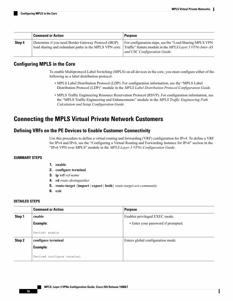
Defining VRFs on the PE Devices to Enable Customer ConnectivityUse this procedure to define a virtual routing and forwarding (VRF) configuration for IPv4. To define a VRFfor IPv4 and IPv6, see the “Configuring a Virtual Routing and Forwarding Instance for IPv6" section in the“IPv6 VPN over MPLS" module in theMPLS Layer 3 VPNs Configuration Guide.
SUMMARY STEPS
1. enable2. configure terminal3. ip vrf vrf-name4. rd route-distinguisher5. route-target {import | export | both} route-target-ext-community6. exit
DETAILED STEPS
PurposeCommand or Action
Enables privileged EXEC mode.enableStep 1
Example: • Enter your password if prompted.
Device> enable
Enters global configuration mode.configure terminal
Example:
Step 2
Device# configure terminal
MPLS: Layer 3 VPNs Configuration Guide, Cisco IOS Release 15M&T10
MPLS Virtual Private NetworksConfiguring MPLS in the Core

PurposeCommand or Action
Defines the virtual private network (VPN) routing instanceby assigning a virtual routing and forwarding (VRF) nameand enters VRF configuration mode.
ip vrf vrf-name
Example:
Device(config)# ip vrf vpn1
Step 3
• The vrf-name argument is the name assigned to a VRF.
Creates routing and forwarding tables.rd route-distinguisherStep 4
Example: • The route-distinguisher argument adds an 8-byte valueto an IPv4 prefix to create a VPN IPv4 prefix. YouDevice(config-vrf)# rd 100:1can enter a route distinguisher (RD) in either of theseformats:
• 16-bit AS number:your 32-bit number, forexample, 101:3
• 32-bit IP address:your 16-bit number, forexample, 10.0.0.1:1
Creates a route-target extended community for a VRF.route-target {import | export | both}route-target-ext-community
Step 5
• The import keyword imports routing information fromthe target VPN extended community.Example:
Device(config-vrf)# route-target both 100:1 • The export keyword exports routing information tothe target VPN extended community.
• The both keyword imports routing information fromand exports routing information to the target VPNextended community.
• The route-target-ext-community argument adds theroute-target extended community attributes to theVRF’s list of import, export, or both route-targetextended communities.
(Optional) Exits to global configuration mode.exit
Example:
Step 6
Device(config-vrf)# exit
Configuring VRF Interfaces on PE Devices for Each VPN CustomerTo associate a virtual routing and forwarding (VRF) instance with an interface or subinterface on the provideredge (PE) devices, perform this task.
SUMMARY STEPS
1. enable2. configure terminal3. interface type number
MPLS: Layer 3 VPNs Configuration Guide, Cisco IOS Release 15M&T11
MPLS Virtual Private NetworksConfiguring VRF Interfaces on PE Devices for Each VPN Customer
4. ip vrf forwarding vrf-name5. end
DETAILED STEPS
PurposeCommand or Action
Enables privileged EXEC mode.enableStep 1
Example: • Enter your password if prompted.
Device> enable
Enters global configuration mode.configure terminal
Example:
Step 2
Device# configure terminal
Specifies the interface to configure and enters interfaceconfiguration mode.
interface type number
Example:
Step 3
• The type argument specifies the type of interface to beconfigured.Device(config)# interface
• The number argument specifies the port, connector,or interface card number.
Associates a VRF with the specified interface orsubinterface.
ip vrf forwarding vrf-name
Example:
Step 4
• The vrf-name argument is the name assigned to a VRF.Device(config-if)# ip vrf forwarding vpn1
(Optional) Exits to privileged EXEC mode.end
Example:
Step 5
Device(config-if)# end
Configuring Routing Protocols Between the PE and CE DevicesConfigure the provider edge (PE) device with the same routing protocol that the customer edge (CE) deviceuses. You can configure the Border Gateway Protocol (BGP), Routing Information Protocol version 2 (RIPv2),or static routes between the PE and CE devices.
Configuring RIPv2 as the Routing Protocol Between the PE and CE Devices
SUMMARY STEPS
1. enable2. configure terminal3. router rip4. version {1 | 2}
MPLS: Layer 3 VPNs Configuration Guide, Cisco IOS Release 15M&T12
MPLS Virtual Private NetworksConfiguring Routing Protocols Between the PE and CE Devices

5. address-family ipv4 [multicast | unicast | vrf vrf-name]6. network ip-address7. redistribute protocol [process-id] {level-1 | level-1-2 | level-2} [as-number] [metric metric-value]
[metric-type type-value] [match {internal | external 1 | external 2}] [tag tag-value] [route-mapmap-tag][subnets]
8. exit-address-family9. end
DETAILED STEPS
PurposeCommand or Action
Enables privileged EXEC mode.enableStep 1
Example: • Enter your password if prompted.
Device> enable
Enters global configuration mode.configure terminal
Example:
Step 2
Device# configure terminal
Enables the Routing Information Protocol (RIP).router rip
Example:
Step 3
Device(config)# router rip
Specifies RIP version used globally by the device.version {1 | 2}
Example:
Step 4
Device(config-router)# version 2
Specifies the IPv4 address family type and enters addressfamily configuration mode.
address-family ipv4 [multicast | unicast | vrf vrf-name]
Example:
Step 5
• Themulticast keyword specifies IPv4 multicastaddress prefixes.Device(config-router)# address-family ipv4 vrf vpn1
• The unicast keyword specifies IPv4 unicast addressprefixes.
• The vrf vrf-name keyword and argument specifies thename of the VRF to associate with subsequent IPv4address family configuration mode commands.
Enables RIP on the PE-to-CE link.network ip-address
Example:
Step 6
Device(config-router-af)# network 192.168.7.0
MPLS: Layer 3 VPNs Configuration Guide, Cisco IOS Release 15M&T13
MPLS Virtual Private NetworksConfiguring RIPv2 as the Routing Protocol Between the PE and CE Devices

PurposeCommand or Action
Redistributes routes from one routing domain into anotherrouting domain.
redistribute protocol [process-id] {level-1 | level-1-2 |level-2} [as-number] [metric metric-value] [metric-type
Step 7
type-value] [match {internal | external 1 | external 2}][tag tag-value] [route-map map-tag] [subnets] • For the RIPv2 routing protocol, use the redistribute
bgp as-number command.Example:
Device(config-router-af)# redistribute bgp 200
Exits address family configuration mode.exit-address-family
Example:
Step 8
Device(config-router-af)# exit-address-family
(Optional) Exits to privileged EXEC mode.end
Example:
Step 9
Device(config-router)# end
Configuring Static Routes Between the PE and CE Devices
SUMMARY STEPS
1. enable2. configure terminal3. ip route vrf vrf-name4. address-family ipv4 [multicast | unicast | vrf vrf-name]5. redistribute protocol [process-id] {level-1 | level-1-2 | level-2} [as-number] [metric metric-value]
[metric-type type-value] [match {internal | external 1 | external 2}] [tag tag-value] [route-mapmap-tag][subnets]
6. redistribute protocol [process-id] {level-1 | level-1-2 | level-2} [as-number] [metric metric-value][metric-type type-value] [match {internal | external 1 | external 2}] [tag tag-value] [route-mapmap-tag][subnets]
7. exit-address-family8. end
DETAILED STEPS
PurposeCommand or Action
Enables privileged EXEC mode.enableStep 1
Example: • Enter your password if prompted.
Device> enable
Enters global configuration mode.configure terminal
Example:
Step 2
MPLS: Layer 3 VPNs Configuration Guide, Cisco IOS Release 15M&T14
MPLS Virtual Private NetworksConfiguring Static Routes Between the PE and CE Devices

PurposeCommand or Action
Device# configure terminal
Defines static route parameters for every provideredge-to-customer edge (PE-to-CE) session and enters routerconfiguration mode.
ip route vrf vrf-name
Example:
Device(config)# ip route vrf vpn1
Step 3
Specifies the IPv4 address family type and enters addressfamily configuration mode.
address-family ipv4 [multicast | unicast | vrf vrf-name]
Example:
Step 4
• Themulticast keyword specifies IPv4 multicastaddress prefixes.Device(config-router)# address-family ipv4 vrf vpn1
• The unicast keyword specifies IPv4 unicast addressprefixes.
• The vrf vrf-name keyword and argument specify thename of the VRF to associate with subsequent IPv4address family configuration mode commands.
Redistributes routes from one routing domain into anotherrouting domain.
redistribute protocol [process-id] {level-1 | level-1-2 |level-2} [as-number] [metric metric-value] [metric-type
Step 5
type-value] [match {internal | external 1 | external 2}][tag tag-value] [route-map map-tag] [subnets] • To redistribute virtual routing and forwarding (VRF)
static routes into the VRF Border Gateway Protocol(BGP) table, use the redistribute static command.Example:
Device(config-router-af)# redistribute static See the command reference page for information aboutother arguments and keywords.
Redistributes routes from one routing domain into anotherrouting domain.
redistribute protocol [process-id] {level-1 | level-1-2 |level-2} [as-number] [metric metric-value] [metric-type
Step 6
type-value] [match {internal | external 1 | external 2}][tag tag-value] [route-map map-tag] [subnets] • To redistribute directly connected networks into the
VRF BGP table, use the redistribute connectedcommand.Example:
Device(config-router-af)# redistribute connected
Exits address family configuration mode.exit-address-family
Example:
Step 7
Device(config-router-af)# exit-address-family
(Optional) Exits to privileged EXEC mode.end
Example:
Step 8
Device(config-router)# end
MPLS: Layer 3 VPNs Configuration Guide, Cisco IOS Release 15M&T15
MPLS Virtual Private NetworksConfiguring Static Routes Between the PE and CE Devices

Verifying the Virtual Private Network ConfigurationA route distinguisher must be configured for the virtual routing and forwarding (VRF) instance, andMultiprotocol Label Switching (MPLS) must be configured on the interfaces that carry the VRF. Use theshow ip vrf command to verify the route distinguisher (RD) and interface that are configured for the VRF.
SUMMARY STEPS
1. show ip vrf
DETAILED STEPS
show ip vrf
Displays the set of defined VRF instances and associated interfaces. The output also maps the VRF instances to theconfigured route distinguisher.
Verifying Connectivity Between MPLS Virtual Private Network SitesTo verify that the local and remote customer edge (CE) devices can communicate across the MultiprotocolLabel Switching (MPLS) core, perform the following tasks:
Verifying IP Connectivity from CE Device to CE Device Across the MPLS Core
SUMMARY STEPS
1. enable2. ping [protocol] {host-name | system-address}3. trace [protocol] [destination]4. show ip route [ip-address [mask] [longer-prefixes]] | protocol [process-id]] | [list [access-list-name |
access-list-number]
DETAILED STEPS
Step 1 enable
Enables privileged EXEC mode.
Step 2 ping [protocol] {host-name | system-address}
Diagnoses basic network connectivity on AppleTalk, Connectionless-modeNetwork Service (CLNS), IP, Novell, Apollo,Virtual Integrated Network Service (VINES), DECnet, or Xerox Network Service (XNS) networks. Use the ping commandto verify the connectivity from one CE device to another.
Step 3 trace [protocol] [destination]
Discovers the routes that packets take when traveling to their destination. The trace command can help isolate a troublespot if two devices cannot communicate.
MPLS: Layer 3 VPNs Configuration Guide, Cisco IOS Release 15M&T16
MPLS Virtual Private NetworksVerifying the Virtual Private Network Configuration

Step 4 show ip route [ip-address [mask] [longer-prefixes]] | protocol [process-id]] | [list [access-list-name | access-list-number]
Displays the current state of the routing table. Use the ip-address argument to verify that CE1 has a route to CE2. Verifythe routes learned by CE1. Make sure that the route for CE2 is listed.
Verifying That the Local and Remote CE Devices Are in the PE Routing Table
SUMMARY STEPS
1. enable2. show ip route vrf vrf-name [prefix]3. show ip cef vrf vrf-name [ip-prefix]
DETAILED STEPS
Step 1 enable
Enables privileged EXEC mode.
Step 2 show ip route vrf vrf-name [prefix]
Displays the IP routing table associated with a virtual routing and forwarding (VRF) instance. Check that the loopbackaddresses of the local and remote customer edge (CE) devices are in the routing table of the provider edge (PE) devices.
Step 3 show ip cef vrf vrf-name [ip-prefix]
Displays the Cisco Express Forwarding forwarding table associated with a VRF. Check that the prefix of the remote CEdevice is in the Cisco Express Forwarding table.
MPLS: Layer 3 VPNs Configuration Guide, Cisco IOS Release 15M&T17
MPLS Virtual Private NetworksVerifying That the Local and Remote CE Devices Are in the PE Routing Table

Configuration Examples for MPLS Virtual Private Networks
Example: Configuring an MPLS Virtual Private Network Using RIPCE ConfigurationPE Configuration
ip cefmpls ldp router-id Loopback0 forcempls label protocol ldp!interface Loopback0ip address 10.0.0.9 255.255.255.255!interfaceip address 192.0.2.1 255.255.255.0no cdp enablerouter ripversion 2timers basic 30 60 60 120redistribute connectednetwork 10.0.0.0network 192.0.2.0no auto-summary
MPLS: Layer 3 VPNs Configuration Guide, Cisco IOS Release 15M&T18
MPLS Virtual Private NetworksConfiguration Examples for MPLS Virtual Private Networks

CE ConfigurationPE Configuration
ip vrf vpn1rd 100:1route-target export 100:1route-target import 100:1!ip cefmpls ldp router-id Loopback0 forcempls label protocol ldp!interface Loopback0ip address 10.0.0.1 255.255.255.255!interfaceip vrf forwarding vpn1ip address 192.0.2.3 255.255.255.0no cdp enableinterfaceip address 192.0.2.2 255.255.255.0mpls label protocol ldpmpls ip!router ripversion 2timers basic 30 60 60 120!address-family ipv4 vrf vpn1version 2redistribute bgp 100 metric transparentnetwork 192.0.2.0distribute-list 20 inno auto-summaryexit-address-family!router bgp 100no synchronizationbgp log-neighbor changesneighbor 10.0.0.3 remote-as 100neighbor 10.0.0.3 update-source Loopback0no auto-summary!address-family vpnv4neighbor 10.0.0.3 activateneighbor 10.0.0.3 send-community extended
bgp scan-time import 5exit-address-family!address-family ipv4 vrf vpn1redistribute connectedredistribute ripno auto-summaryno synchronizationexit-address-family
MPLS: Layer 3 VPNs Configuration Guide, Cisco IOS Release 15M&T19
MPLS Virtual Private NetworksExample: Configuring an MPLS Virtual Private Network Using RIP

Example: Configuring an MPLS Virtual Private Network Using Static RoutesCE ConfigurationPE Configuration
ip cef!interface Loopback0ip address 10.0.0.9 255.255.255.255!interfaceip address 192.0.2.2 255.255.0.0no cdp enable!ip route 10.0.0.9 255.255.255.255 192.0.2.33ip route 198.51.100.0 255.255.255.0 192.0.2.33
ip vrf vpn1rd 100:1route-target export 100:1route-target import 100:1!ip cefmpls ldp router-id Loopback0 forcempls label protocol ldp!interface Loopback0ip address 10.0.0.1 255.255.255.255!interfaceip vrf forwarding vpn1ip address 192.0.2.3 255.255.255.0no cdp enable!interfaceip address 192.168.0.1 255.255.0.0mpls label protocol ldpmpls ip!router ospf 100network 10.0.0. 0.0.0.0 area 100network 192.168.0.0 255.255.0.0 area 100!router bgp 100no synchronizationbgp log-neighbor changesneighbor 10.0.0.3 remote-as 100neighbor 10.0.0.3 update-source Loopback0no auto-summary!address-family vpnv4neighbor 10.0.0.3 activateneighbor 10.0.0.3 send-community extendedbgp scan-time import 5exit-address-family!address-family ipv4 vrf vpn1redistribute connectedredistribute staticno auto-summaryno synchronizationexit-address-family!ip route vrf vpn1 10.0.0.9 255.255.255.255192.0.2.2ip route vrf vpn1 192.0.2.0 255.255.0.0192.0.2.2
MPLS: Layer 3 VPNs Configuration Guide, Cisco IOS Release 15M&T20
MPLS Virtual Private NetworksExample: Configuring an MPLS Virtual Private Network Using Static Routes
Additional ReferencesRelated Documents
Document TitleRelated Topic
Cisco IOS Master Command List, All ReleasesCisco IOS commands
Cisco IOSMultiprotocol Label Switching CommandReferenceDescription of commands associated withMPLS and MPLS applications
“Configuring Basic Cisco Express Forwarding” module in theCisco Express Forwarding Configuration Guide
Configuring Cisco Express Forwarding
“Load SharingMPLS VPN Traffic” module in theMPLS Layer3 VPNs Inter-AS and CSC Configuration Guide
Border Gateway Protocol (BGP) loadsharing
“MPLSLabel Distribution Protocol (LDP)”module in theMPLSLabel Distribution Protocol Configuration Guide
Configuring LDP
“"MPLSTraffic Engineering and Enhancements”module in theMPLS Traffic Engineering Path Calculation and SetupConfiguration Guide
Configuring MPLS Traffic EngineeringResource Reservation Protocol (RSVP)
“IPv6 VPN over MPLS” module in theMPLS Layer 3 VPNsConfiguration Guide
IPv6 VPN over MPLS
Technical Assistance
LinkDescription
http://www.cisco.com/cisco/web/support/index.htmlTheCisco Support andDocumentationwebsite providesonline resources to download documentation, software,and tools. Use these resources to install and configurethe software and to troubleshoot and resolve technicalissues with Cisco products and technologies. Access tomost tools on the Cisco Support and Documentationwebsite requires a Cisco.com user ID and password.
Feature Information for MPLS Virtual Private NetworksThe following table provides release information about the feature or features described in this module. Thistable lists only the software release that introduced support for a given feature in a given software releasetrain. Unless noted otherwise, subsequent releases of that software release train also support that feature.
Use Cisco Feature Navigator to find information about platform support and Cisco software image support.To access Cisco Feature Navigator, go to www.cisco.com/go/cfn. An account on Cisco.com is not required.
MPLS: Layer 3 VPNs Configuration Guide, Cisco IOS Release 15M&T21
MPLS Virtual Private NetworksAdditional References
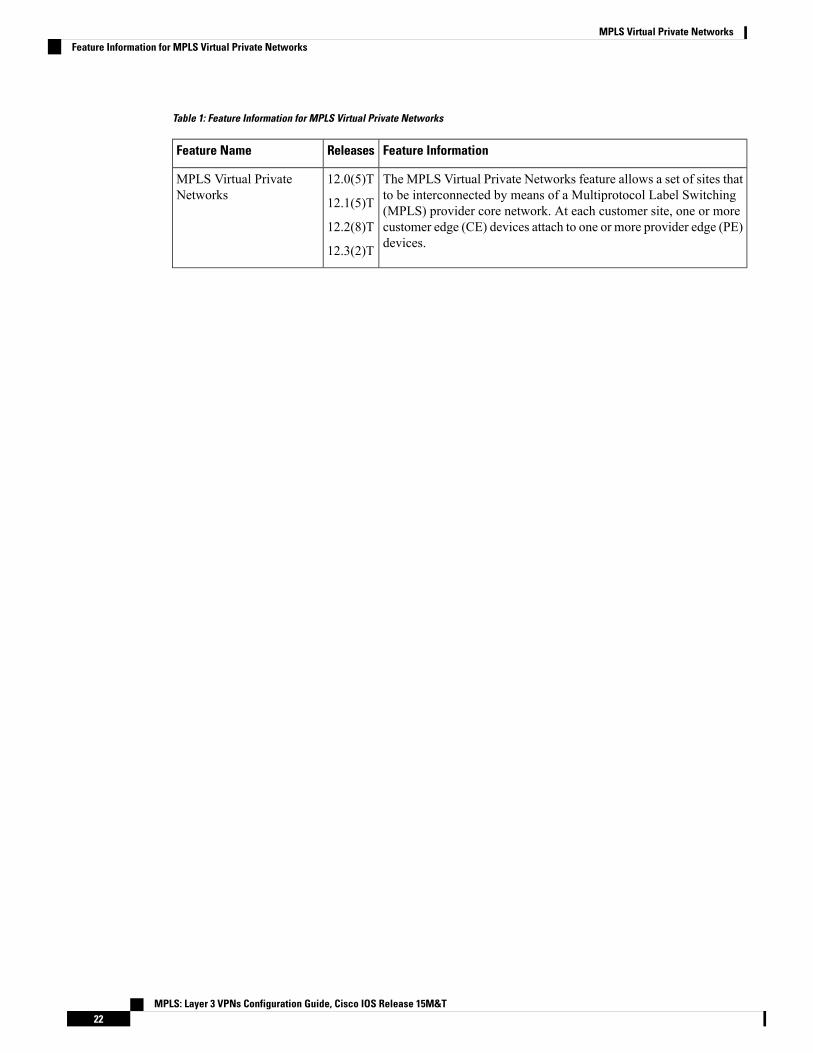
Table 1: Feature Information for MPLS Virtual Private Networks
Feature InformationReleasesFeature Name
The MPLS Virtual Private Networks feature allows a set of sites thatto be interconnected by means of a Multiprotocol Label Switching(MPLS) provider core network. At each customer site, one or morecustomer edge (CE) devices attach to one or more provider edge (PE)devices.
12.0(5)T
12.1(5)T
12.2(8)T
12.3(2)T
MPLS Virtual PrivateNetworks
MPLS: Layer 3 VPNs Configuration Guide, Cisco IOS Release 15M&T22
MPLS Virtual Private NetworksFeature Information for MPLS Virtual Private Networks
C H A P T E R 2Multiprotocol BGP MPLS VPN
A Multiprotocol Label Switching (MPLS) virtual private network (VPN) consists of a set of sites that areinterconnected by means of an MPLS provider core network. At each site, there are one or more customeredge (CE) devices, which attach to one or more provider edge (PE) devices. PEs use theMultiprotocol-BorderGateway Protocol (MP-BGP) to dynamically communicate with each other.
• Finding Feature Information, on page 23• Prerequisites for Multiprotocol BGP MPLS VPN, on page 23• Information About Multiprotocol BGP MPLS VPN, on page 24• How to Configure Multiprotocol BGP MPLS VPN, on page 27• Configuration Examples for Multiprotocol BGP MPLS VPN, on page 34• Additional References, on page 35• Feature Information for Multiprotocol BGP MPLS VPN, on page 35
Finding Feature InformationYour software release may not support all the features documented in this module. For the latest caveats andfeature information, see Bug Search Tool and the release notes for your platform and software release. Tofind information about the features documented in this module, and to see a list of the releases in which eachfeature is supported, see the feature information table.
Use Cisco Feature Navigator to find information about platform support and Cisco software image support.To access Cisco Feature Navigator, go to www.cisco.com/go/cfn. An account on Cisco.com is not required.
Prerequisites for Multiprotocol BGP MPLS VPNConfigure MPLS virtual private networks (VPNs) in the core.
MPLS: Layer 3 VPNs Configuration Guide, Cisco IOS Release 15M&T23
Information About Multiprotocol BGP MPLS VPN
MPLS Virtual Private Network DefinitionBefore defining a Multiprotocol Label Switching virtual private network (MPLS VPN), you must define aVPN in general. A VPN is:
• An IP-based network delivering private network services over a public infrastructure
• A set of sites that are allowed to communicate with each other privately over the Internet or other publicor private networks
Conventional VPNs are created by configuring a full mesh of tunnels or permanent virtual circuits (PVCs) toall sites in a VPN. This type of VPN is not easy to maintain or expand, because adding a new site requireschanging each edge device in the VPN.
MPLS-based VPNs are created in Layer 3 and are based on the peer model. The peer model enables the serviceprovider and the customer to exchange Layer 3 routing information. The service provider relays the databetween the customer sites without the customer’s involvement.
MPLSVPNs are easier to manage and expand than conventional VPNs.When a new site is added to anMPLSVPN, only the service provider’s edge device that provides services to the customer site needs to be updated.
The different parts of the MPLS VPN are described as follows:
• Provider (P) device—Device in the core of the provider network. P devices run MPLS switching, anddo not attach VPN labels to routed packets. The MPLS label in each route is assigned by the provideredge (PE) device. VPN labels are used to direct data packets to the correct egress device.
• PE device—Device that attaches the VPN label to incoming packets based on the interface or subinterfaceon which they are received. A PE device attaches directly to a customer edge (CE) device.
• Customer (C) device—Device in the ISP or enterprise network.
• CE device—Edge device on the network of the ISP that connects to the PE device on the network. A CEdevice must interface with a PE device.
The figure below shows a basic MPLS VPN.
MPLS: Layer 3 VPNs Configuration Guide, Cisco IOS Release 15M&T24
Multiprotocol BGP MPLS VPNInformation About Multiprotocol BGP MPLS VPN

Figure 2: Basic MPLS VPN Terminology
How an MPLS Virtual Private Network WorksMultiprotocol Label Switching virtual private network (MPLS VPN) functionality is enabled at the edge ofan MPLS network. The provider edge (PE) device performs the following:
• Exchanges routing updates with the customer edge (CE) device.
• Translates the CE routing information into VPNv4 routes.
• Exchanges VPNv4 routes with other PE devices through the Multiprotocol Border Gateway Protocol(MP-BGP).
The following sections describe how MPLS VPN works:
How Virtual Routing and Forwarding Tables Work in an MPLS Virtual Private NetworkEach virtual private network (VPN) is associated with one or more virtual routing and forwarding (VRF)instances. A VRF defines the VPN membership of a customer site attached to a PE device. A VRF consistsof the following components:
• An IP routing table
• A derived Cisco Express Forwarding table
• A set of interfaces that use the forwarding table
• A set of rules and routing protocol parameters that control the information that is included in the routingtable
A one-to-one relationship does not necessarily exist between customer sites and VPNs. A site can be a memberof multiple VPNs. However, a site can associate with only one VRF. A site’s VRF contains all the routesavailable to the site from the VPNs of which it is a member.
Packet forwarding information is stored in the IP routing table and the Cisco Express Forwarding table foreach VRF. A separate set of routing and Cisco Express Forwarding tables is maintained for each VRF. These
MPLS: Layer 3 VPNs Configuration Guide, Cisco IOS Release 15M&T25
Multiprotocol BGP MPLS VPNHow an MPLS Virtual Private Network Works
tables prevent information from being forwarded outside a VPN, and they also prevent packets that are outsidea VPN from being forwarded to a device within the VPN.
How VPN Routing Information Is Distributed in an MPLS Virtual Private NetworkThe distribution of virtual private network (VPN) routing information is controlled through the use of VPNroute target communities, implemented by Border Gateway Protocol (BGP) extended communities. VPNrouting information is distributed as follows:
• When a VPN route that is learned from a customer edge (CE) device is injected into BGP, a list of VPNroute target extended community attributes is associatedwith it. Typically the list of route target communityextended values is set from an export list of route targets associated with the virtual routing and forwarding(VRF) instance from which the route was learned.
• An import list of route target extended communities is associated with each VRF. The import list definesroute target extended community attributes that a route must have in order for the route to be importedinto the VRF. For example, if the import list for a particular VRF includes route target extendedcommunities A, B, and C, then any VPN route that carries any of those route target extendedcommunities—A, B, or C—is imported into the VRF.
MPLS ForwardingBased on routing information stored in the virtual routing and forwarding (VRF) IP routing table and VRFCisco Express Forwarding table, packets are forwarded to their destination usingMultiprotocol Label Switching(MPLS).
A provider edge (PE) device binds a label to each customer prefix learned from a customer edge (CE) deviceand includes the label in the network reachability information for the prefix that it advertises to other PEdevices. When a PE device forwards a packet received from a CE device across the provider network, it labelsthe packet with the label learned from the destination PE device. When the destination PE device receives thelabeled packet, it pops the label and uses it to direct the packet to the correct CE device. Label forwardingacross the provider backbone is based on either dynamic label switching or traffic engineered paths. A customerdata packet carries two levels of labels when traversing the backbone:
• The top label directs the packet to the correct PE device.
• The second label indicates how that PE device should forward the packet to the CE device.
BGP Distribution of VPN Routing InformationA provider edge (PE) device can learn an IP prefix from the following sources:
• A customer edge (CE) device by static configuration
• A Border Gateway Protocol (BGP) session with the CE device
• A Routing Information Protocol (RIP) exchange with the CE device
The IP prefix is a member of the IPv4 address family. After the PE device learns the IP prefix, the PE convertsit into a VPN-IPv4 prefix by combining it with an 8-byte route distinguisher (RD). The generated prefix is amember of the VPN-IPv4 address family. It uniquely identifies the customer address, even if the customersite is using globally nonunique (unregistered private) IP addresses. The route distinguisher used to generatethe VPN-IPv4 prefix is specified by a configuration command associatedwith the virtual routing and forwarding(VRF) instance on the PE device.
MPLS: Layer 3 VPNs Configuration Guide, Cisco IOS Release 15M&T26
Multiprotocol BGP MPLS VPNHow VPN Routing Information Is Distributed in an MPLS Virtual Private Network

BGP distributes reachability information for VPN-IPv4 prefixes for each VPN. BGP communication occursat two levels:
• Within an IP domains, known as an autonomous system (interior BGP [IBGP])
• Between autonomous systems (external BGP [EBGP])
PE-PE or PE-RR (route reflector) sessions are IBGP sessions, and PE-CE sessions are EBGP sessions. In anEnhanced Interior Gateway Routing Protocol (EIGRP) PE-CE environment, when an EIGRP internal routeis redistributed into BGP by one PE, and then back into EIGRP by another PE, the originating router ID forthe route is set to the router ID of the second PE, replacing the original internal router ID.
BGP propagates reachability information for VPN-IPv4 prefixes among PE devices by means of the BGPmultiprotocol extensions (refer to RFC 2283,Multiprotocol Extensions for BGP-4), which define support foraddress families other than IPv4. Using the extensions ensures that the routes for a given VPN are learnedonly by other members of that VPN, enabling members of the VPN to communicate with each other.
Major Components of an MPLS Virtual Private NetworkAnMultiprotocol Label Switching (MPLS)-based virtual private network (VPN) has three major components:
• VPN route target communities—A VPN route target community is a list of all members of a VPNcommunity. VPN route targets need to be configured for each VPN community member.
• Multiprotocol BGP (MP-BGP) peering of VPN community provider edge (PE) devices—MP-BGPpropagates virtual routing and forwarding (VRF) reachability information to all members of a VPNcommunity. MP-BGP peering must be configured on all PE devices within a VPN community.
• MPLS forwarding—MPLS transports all traffic between all VPN community members across a VPNservice-provider network.
A one-to-one relationship does not necessarily exist between customer sites and VPNs. A given site can be amember of multiple VPNs. However, a site can associate with only one VRF. A customer-site VRF containsall the routes available to the site from the VPNs of which it is a member.
How to Configure Multiprotocol BGP MPLS VPN
Configuring Multiprotocol BGP Connectivity on the PE Devices and RouteReflectors
SUMMARY STEPS
1. enable2. configure terminal3. router bgp as-number4. no bgp default ipv4-unicast5. neighbor {ip-address | peer-group-name} remote-as as-number6. neighbor {ip-address | peer-group-name} activate7. address-family vpnv4 [unicast]
MPLS: Layer 3 VPNs Configuration Guide, Cisco IOS Release 15M&T27
Multiprotocol BGP MPLS VPNMajor Components of an MPLS Virtual Private Network

8. neighbor {ip-address | peer-group-name} send-community extended9. neighbor {ip-address | peer-group-name} activate10. end
DETAILED STEPS
PurposeCommand or Action
Enables privileged EXEC mode.enableStep 1
Example: • Enter your password if prompted.
Device> enable
Enters global configuration mode.configure terminal
Example:
Step 2
Device# configure terminal
Configures a Border Gateway Protocol (BGP) routingprocess and enters router configuration mode.
router bgp as-number
Example:
Step 3
• The as-number argument indicates the number of anautonomous system that identifies the device to otherDevice(config)# router bgp 100
BGP devices and tags the routing information passedalong. The range is 0 to 65535. Private autonomoussystem numbers that can be used in internal networksare 64512 to 65535.
(Optional) Disables the IPv4 unicast address family on allneighbors.
no bgp default ipv4-unicast
Example:
Step 4
• Use the no bgp default ipv4-unicast command ifyou are using this neighbor for Multiprotocol LabelSwitching (MPLS) routes only.
Device(config-router)# no bgp default ipv4-unicast
Adds an entry to the BGP or multiprotocol BGP neighbortable.
neighbor {ip-address | peer-group-name} remote-asas-number
Step 5
Example: • The ip-address argument specifies the IP address ofthe neighbor.
Device(config-router)# neighbor 10.0.0.1 remote-as100 • The peer-group-name argument specifies the name
of a BGP peer group.
• The as-number argument specifies the autonomoussystem to which the neighbor belongs.
Enables the exchange of information with a neighboringBGP device.
neighbor {ip-address | peer-group-name} activate
Example:
Step 6
• The ip-address argument specifies the IP address ofthe neighbor.Device(config-router)# neighbor 10.0.0.1 activate
MPLS: Layer 3 VPNs Configuration Guide, Cisco IOS Release 15M&T28
Multiprotocol BGP MPLS VPNConfiguring Multiprotocol BGP Connectivity on the PE Devices and Route Reflectors

PurposeCommand or Action
• The peer-group-name argument specifies the nameof a BGP peer group.
Enters address family configuration mode for configuringrouting sessions, such as BGP, that use standard VPNv4address prefixes.
address-family vpnv4 [unicast]
Example:
Device(config-router)# address-family vpnv4
Step 7
• The optional unicast keyword specifies VPNv4unicast address prefixes.
Specifies that a communities attribute should be sent to aBGP neighbor.
neighbor {ip-address | peer-group-name}send-community extended
Step 8
Example: • The ip-address argument specifies the IP address ofthe BGP-speaking neighbor.
Device(config-router-af)# neighbor 10.0.0.1send-community extended • The peer-group-name argument specifies the name
of a BGP peer group.
Enables the exchange of information with a neighboringBGP device.
neighbor {ip-address | peer-group-name} activate
Example:
Step 9
• The ip-address argument specifies the IP address ofthe neighbor.Device(config-router-af)# neighbor 10.0.0.1
activate• The peer-group-name argument specifies the nameof a BGP peer group.
(Optional) Exits to privileged EXEC mode.end
Example:
Step 10
Device(config-router-af)# end
Troubleshooting TipsYou can enter a show ip bgp neighbor command to verify that the neighbors are up and running. If thiscommand is not successful, enter a debug ip bgp ip-address events command, where ip-address is the IPaddress of the neighbor.
Configuring BGP as the Routing Protocol Between the PE and CE Devices
SUMMARY STEPS
1. enable2. configure terminal3. router bgp as-number4. address-family ipv4 [multicast | unicast | vrf vrf-name]5. neighbor {ip-address | peer-group-name} remote-as as-number
MPLS: Layer 3 VPNs Configuration Guide, Cisco IOS Release 15M&T29
Multiprotocol BGP MPLS VPNTroubleshooting Tips
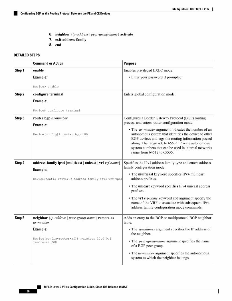
6. neighbor {ip-address | peer-group-name} activate7. exit-address-family8. end
DETAILED STEPS
PurposeCommand or Action
Enables privileged EXEC mode.enableStep 1
Example: • Enter your password if prompted.
Device> enable
Enters global configuration mode.configure terminal
Example:
Step 2
Device# configure terminal
Configures a Border Gateway Protocol (BGP) routingprocess and enters router configuration mode.
router bgp as-number
Example:
Step 3
• The as-number argument indicates the number of anautonomous system that identifies the device to otherDevice(config)# router bgp 100
BGP devices and tags the routing information passedalong. The range is 0 to 65535. Private autonomoussystem numbers that can be used in internal networksrange from 64512 to 65535.
Specifies the IPv4 address family type and enters addressfamily configuration mode.
address-family ipv4 [multicast | unicast | vrf vrf-name]
Example:
Step 4
• Themulticast keyword specifies IPv4 multicastaddress prefixes.Device(config-router)# address-family ipv4 vrf vpn1
• The unicast keyword specifies IPv4 unicast addressprefixes.
• The vrf vrf-name keyword and argument specify thename of the VRF to associate with subsequent IPv4address family configuration mode commands.
Adds an entry to the BGP or multiprotocol BGP neighbortable.
neighbor {ip-address | peer-group-name} remote-asas-number
Step 5
Example: • The ip-address argument specifies the IP address ofthe neighbor.
Device(config-router-af)# neighbor 10.0.0.1remote-as 200 • The peer-group-name argument specifies the name
of a BGP peer group.
• The as-number argument specifies the autonomoussystem to which the neighbor belongs.
MPLS: Layer 3 VPNs Configuration Guide, Cisco IOS Release 15M&T30
Multiprotocol BGP MPLS VPNConfiguring BGP as the Routing Protocol Between the PE and CE Devices

PurposeCommand or Action
Enables the exchange of information with a neighboringBGP device.
neighbor {ip-address | peer-group-name} activate
Example:
Step 6
• The ip-address argument specifies the IP address ofthe neighbor.Device(config-router-af)# neighbor 10.0.0.1
activate• The peer-group-name argument specifies the nameof a BGP peer group.
Exits address family configuration mode.exit-address-family
Example:
Step 7
Device(config-router-af)# exit-address-family
(Optional) Exits to privileged EXEC mode.end
Example:
Step 8
Device(config-router)# end
Verifying the Virtual Private Network ConfigurationA route distinguisher must be configured for the virtual routing and forwarding (VRF) instance, andMultiprotocol Label Switching (MPLS) must be configured on the interfaces that carry the VRF. Use theshow ip vrf command to verify the route distinguisher (RD) and interface that are configured for the VRF.
SUMMARY STEPS
1. show ip vrf
DETAILED STEPS
show ip vrf
Displays the set of defined VRF instances and associated interfaces. The output also maps the VRF instances to theconfigured route distinguisher.
Verifying Connectivity Between MPLS Virtual Private Network SitesTo verify that the local and remote customer edge (CE) devices can communicate across the MultiprotocolLabel Switching (MPLS) core, perform the following tasks:
MPLS: Layer 3 VPNs Configuration Guide, Cisco IOS Release 15M&T31
Multiprotocol BGP MPLS VPNVerifying the Virtual Private Network Configuration

Verifying IP Connectivity from CE Device to CE Device Across the MPLS Core
SUMMARY STEPS
1. enable2. ping [protocol] {host-name | system-address}3. trace [protocol] [destination]4. show ip route [ip-address [mask] [longer-prefixes]] | protocol [process-id]] | [list [access-list-name |
access-list-number]
DETAILED STEPS
Step 1 enable
Enables privileged EXEC mode.
Step 2 ping [protocol] {host-name | system-address}
Diagnoses basic network connectivity on AppleTalk, Connectionless-modeNetwork Service (CLNS), IP, Novell, Apollo,Virtual Integrated Network Service (VINES), DECnet, or Xerox Network Service (XNS) networks. Use the ping commandto verify the connectivity from one CE device to another.
Step 3 trace [protocol] [destination]
Discovers the routes that packets take when traveling to their destination. The trace command can help isolate a troublespot if two devices cannot communicate.
Step 4 show ip route [ip-address [mask] [longer-prefixes]] | protocol [process-id]] | [list [access-list-name | access-list-number]
Displays the current state of the routing table. Use the ip-address argument to verify that CE1 has a route to CE2. Verifythe routes learned by CE1. Make sure that the route for CE2 is listed.
Verifying That the Local and Remote CE Devices Are in the PE Routing Table
SUMMARY STEPS
1. enable2. show ip route vrf vrf-name [prefix]3. show ip cef vrf vrf-name [ip-prefix]
DETAILED STEPS
Step 1 enable
Enables privileged EXEC mode.
Step 2 show ip route vrf vrf-name [prefix]
Displays the IP routing table associated with a virtual routing and forwarding (VRF) instance. Check that the loopbackaddresses of the local and remote customer edge (CE) devices are in the routing table of the provider edge (PE) devices.
MPLS: Layer 3 VPNs Configuration Guide, Cisco IOS Release 15M&T32
Multiprotocol BGP MPLS VPNVerifying IP Connectivity from CE Device to CE Device Across the MPLS Core

Step 3 show ip cef vrf vrf-name [ip-prefix]
Displays the Cisco Express Forwarding forwarding table associated with a VRF. Check that the prefix of the remote CEdevice is in the Cisco Express Forwarding table.
MPLS: Layer 3 VPNs Configuration Guide, Cisco IOS Release 15M&T33
Multiprotocol BGP MPLS VPNVerifying That the Local and Remote CE Devices Are in the PE Routing Table
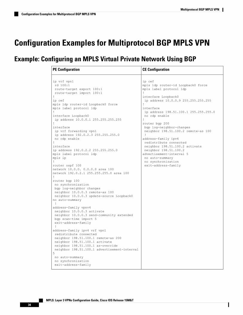
Configuration Examples for Multiprotocol BGP MPLS VPN
Example: Configuring an MPLS Virtual Private Network Using BGPCE ConfigurationPE Configuration
ip cefmpls ldp router-id Loopback0 forcempls label protocol ldp!interface Loopback0ip address 10.0.0.9 255.255.255.255!interfaceip address 198.51.100.1 255.255.255.0no cdp enable!router bgp 200bgp log-neighbor-changesneighbor 198.51.100.2 remote-as 100!address-family ipv4redistribute connectedneighbor 198.51.100.2 activateneighbor 198.51.100.2advertisement-interval 5no auto-summaryno synchronizationexit-address-family
ip vrf vpn1rd 100:1route-target export 100:1route-target import 100:1!ip cefmpls ldp router-id Loopback0 forcempls label protocol ldp!interface Loopback0ip address 10.0.0.1 255.255.255.255!interfaceip vrf forwarding vpn1ip address 192.0.2.3 255.255.255.0no cdp enable!interfaceip address 192.0.2.2 255.255.255.0mpls label protocol ldpmpls ip!router ospf 100network 10.0.0. 0.0.0.0 area 100network 192.0.2.1 255.255.255.0 area 100!router bgp 100no synchronizationbgp log-neighbor changesneighbor 10.0.0.3 remote-as 100neighbor 10.0.0.3 update-source Loopback0no auto-summary!address-family vpnv4neighbor 10.0.0.3 activateneighbor 10.0.0.3 send-community extendedbgp scan-time import 5exit-address-family!address-family ipv4 vrf vpn1redistribute connectedneighbor 198.51.100.1 remote-as 200neighbor 198.51.100.1 activateneighbor 198.51.100.1 as-overrideneighbor 198.51.100.1 advertisement-interval5no auto-summaryno synchronizationexit-address-family
MPLS: Layer 3 VPNs Configuration Guide, Cisco IOS Release 15M&T34
Multiprotocol BGP MPLS VPNConfiguration Examples for Multiprotocol BGP MPLS VPN
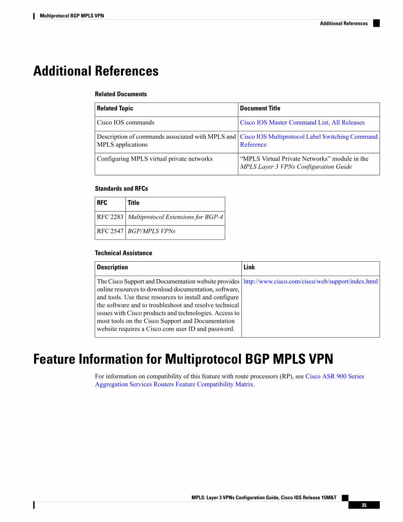
Additional ReferencesRelated Documents
Document TitleRelated Topic
Cisco IOS Master Command List, All ReleasesCisco IOS commands
Cisco IOSMultiprotocol Label Switching CommandReference
Description of commands associated with MPLS andMPLS applications
“MPLS Virtual Private Networks” module in theMPLS Layer 3 VPNs Configuration Guide
Configuring MPLS virtual private networks
Standards and RFCs
TitleRFC
Multiprotocol Extensions for BGP-4RFC2283
BGP/MPLS VPNsRFC2547
Technical Assistance
LinkDescription
http://www.cisco.com/cisco/web/support/index.htmlTheCisco Support andDocumentationwebsite providesonline resources to download documentation, software,and tools. Use these resources to install and configurethe software and to troubleshoot and resolve technicalissues with Cisco products and technologies. Access tomost tools on the Cisco Support and Documentationwebsite requires a Cisco.com user ID and password.
Feature Information for Multiprotocol BGP MPLS VPNFor information on compatibility of this feature with route processors (RP), see Cisco ASR 900 SeriesAggregation Services Routers Feature Compatibility Matrix.
MPLS: Layer 3 VPNs Configuration Guide, Cisco IOS Release 15M&T35
Multiprotocol BGP MPLS VPNAdditional References
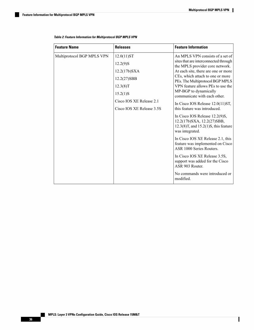
Table 2: Feature Information for Multiprotocol BGP MPLS VPN
Feature InformationReleasesFeature Name
An MPLS VPN consists of a set ofsites that are interconnected throughthe MPLS provider core network.At each site, there are one or moreCEs, which attach to one or morePEs. TheMultiprotocol BGPMPLSVPN feature allows PEs to use theMP-BGP to dynamicallycommunicate with each other.
In Cisco IOS Release 12.0(11)ST,this feature was introduced.
In Cisco IOS Release 12.2(9)S,12.2(17b)SXA, 12.2(27)SBB,12.3(8)T, and 15.2(1)S, this featurewas integrated.
In Cisco IOS XE Release 2.1, thisfeature was implemented on CiscoASR 1000 Series Routers.
In Cisco IOS XE Release 3.5S,support was added for the CiscoASR 903 Router.
No commands were introduced ormodified.
12.0(11)ST
12.2(9)S
12.2(17b)SXA
12.2(27)SBB
12.3(8)T
15.2(1)S
Cisco IOS XE Release 2.1
Cisco IOS XE Release 3.5S
Multiprotocol BGP MPLS VPN
MPLS: Layer 3 VPNs Configuration Guide, Cisco IOS Release 15M&T36
Multiprotocol BGP MPLS VPNFeature Information for Multiprotocol BGP MPLS VPN

C H A P T E R 3MPLS VPN OSPF PE and CE Support
The MPLS VPN OSPF PE and CE Support feature allows service providers to configure Open Shortest PathFirst (OSPF) between provider edge (PE) and customer edge (CE) devices in aMultiprotocol Label Switching(MPLS) virtual private network ( VPN). This feature increases flexibility when devices exchange routinginformation among sites because a separate router ID for each interface or subinterface is configured on a PEdevice attached to multiple CE devices within a VPN. An MPLS VPN consists of a set of sites that areinterconnected by means of an MPLS provider core network. At each customer site, one or more CE devicesattach to one or more PE devices.
• Finding Feature Information, on page 37• Prerequisites for MPLS VPN OSPF PE and CE Support, on page 37• Information About MPLS VPN OSPF PE and CE Support, on page 38• How to Configure MPLS VPN OSPF PE and CE Support, on page 38• Configuration Examples for MPLS VPN OSPF PE and CE Support, on page 42• Additional References, on page 43• Feature Information for MPLS VPN OSPF PE and CE Support, on page 43
Finding Feature InformationYour software release may not support all the features documented in this module. For the latest caveats andfeature information, see Bug Search Tool and the release notes for your platform and software release. Tofind information about the features documented in this module, and to see a list of the releases in which eachfeature is supported, see the feature information table.
Use Cisco Feature Navigator to find information about platform support and Cisco software image support.To access Cisco Feature Navigator, go to www.cisco.com/go/cfn. An account on Cisco.com is not required.
Prerequisites for MPLS VPN OSPF PE and CE Support• Configure MPLS Layer 3 VPNs.
• Configure the Border Gateway Protocol (BGP) in the core.
MPLS: Layer 3 VPNs Configuration Guide, Cisco IOS Release 15M&T37

Information About MPLS VPN OSPF PE and CE Support
Overview of MPLS VPN OSPF PE and CE SupportThis feature allows service providers to configure Open Shortest Path First (OSPF) between provider edge(PE) and customer edge (CE) devices in an MPLS VPN network.
This feature increases flexibility when devices exchange routing information among sites because a separaterouter ID for each interface or subinterface is configured on a PE device attached to multiple CE deviceswithin a VPN.
How to Configure MPLS VPN OSPF PE and CE Support
Configuring OSPF as the Routing Protocol Between the PE and CE DevicesPerform this task to configure PE-to-CE routing sessions that use Open Shortest Path First (OSPF).
The Cisco implementation of OSPF in an MPLS VPN PE-CE environment is compliant with RFC 4576.Note
Before you begin
Configure the PE device with the same routing protocol that the CE device uses.
SUMMARY STEPS
1. enable2. configure terminal3. router ospf process-id [vrf vpn-name]4. network ip-address wildcard-mask area area-id5. address-family ipv4 [multicast | unicast | vrf vrf-name]6. redistribute protocol | [process-id] | {level-1 | level-1-2 | level-2} [as-number] [metric metric-value]
[metric-type type-value] [match {internal | external 1 | external 2}] [tag tag-value] [route-mapmap-tag][subnets]
7. exit-address-family8. end
DETAILED STEPS
PurposeCommand or Action
Enables privileged EXEC mode.enableStep 1
Example: • Enter your password if prompted.
MPLS: Layer 3 VPNs Configuration Guide, Cisco IOS Release 15M&T38
MPLS VPN OSPF PE and CE SupportInformation About MPLS VPN OSPF PE and CE Support

PurposeCommand or Action
Device> enable
Enters global configuration mode.configure terminal
Example:
Step 2
Device# configure terminal
Enables OSPF routing and enters router configurationmode.router ospf process-id [vrf vpn-name]Step 3
Example: • The process-id argument identifies the OSPF process.
Device(config)# router ospf 1 vrf grc • The vrf vpn-name keyword and argument identify avirtual private network (VPN). Create a separate OSPFprocess for each virtual routing and forwarding (VRF)instance that will receive VPN routes.
Defines the interfaces on which OSPF runs and to definesthe area ID for those interfaces.
network ip-address wildcard-mask area area-id
Example:
Step 4
• The ip-address argument identifies the IP address.Device(config-router)# network 10.0.0.1 0.0.0.3area 20 • The wildcard-mask argument identifies the
IP-address-type mask that includes “don’t care” bits.
• The area-id argument identifies the area that is to beassociated with the OSPF address range. It can bespecified as either a decimal value or an IP address.To associate areas with IP subnets, specify a subnetaddress as the value of the area-id argument.
Specifies the IPv4 address family type and enters addressfamily configuration mode.
address-family ipv4 [multicast | unicast | vrf vrf-name]
Example:
Step 5
• Themulticast keyword specifies IPv4 multicastaddress prefixes.Device(config-router)# address-family ipv4 vrf vpn1
• The unicast keyword specifies IPv4 unicast addressprefixes.
• The vrf vrf-name keyword and argument specify thename of the VRF to associate with subsequent IPv4address family configuration mode commands.
Redistributes routes from one routing domain into anotherrouting domain.
redistribute protocol | [process-id] | {level-1 | level-1-2 |level-2} [as-number] [metric metric-value] [metric-type
Step 6
type-value] [match {internal | external 1 | external 2}][tag tag-value] [route-map map-tag] [subnets] You may need to include several protocols to ensure that
all interior Border Gateway Protocol (IBGP) routes aredistributed into the VRF.Example:
Device(config-router-af)# redistribute rip metric1 subnets
MPLS: Layer 3 VPNs Configuration Guide, Cisco IOS Release 15M&T39
MPLS VPN OSPF PE and CE SupportConfiguring OSPF as the Routing Protocol Between the PE and CE Devices

PurposeCommand or Action
Exits address family configuration mode.exit-address-family
Example:
Step 7
Device(config-router-af)# exit-address-family
(Optional) Exits to privileged EXEC mode.end
Example:
Step 8
Device(config-router)# end
Verifying Connectivity Between MPLS Virtual Private Network SitesTo verify that the local and remote customer edge (CE) devices can communicate across the MultiprotocolLabel Switching (MPLS) core, perform the following tasks:
Verifying IP Connectivity from CE Device to CE Device Across the MPLS Core
SUMMARY STEPS
1. enable2. ping [protocol] {host-name | system-address}3. trace [protocol] [destination]4. show ip route [ip-address [mask] [longer-prefixes]] | protocol [process-id]] | [list [access-list-name |
access-list-number]
DETAILED STEPS
Step 1 enable
Enables privileged EXEC mode.
Step 2 ping [protocol] {host-name | system-address}
Diagnoses basic network connectivity on AppleTalk, Connectionless-modeNetwork Service (CLNS), IP, Novell, Apollo,Virtual Integrated Network Service (VINES), DECnet, or Xerox Network Service (XNS) networks. Use the ping commandto verify the connectivity from one CE device to another.
Step 3 trace [protocol] [destination]
Discovers the routes that packets take when traveling to their destination. The trace command can help isolate a troublespot if two devices cannot communicate.
Step 4 show ip route [ip-address [mask] [longer-prefixes]] | protocol [process-id]] | [list [access-list-name | access-list-number]
Displays the current state of the routing table. Use the ip-address argument to verify that CE1 has a route to CE2. Verifythe routes learned by CE1. Make sure that the route for CE2 is listed.
MPLS: Layer 3 VPNs Configuration Guide, Cisco IOS Release 15M&T40
MPLS VPN OSPF PE and CE SupportVerifying Connectivity Between MPLS Virtual Private Network Sites
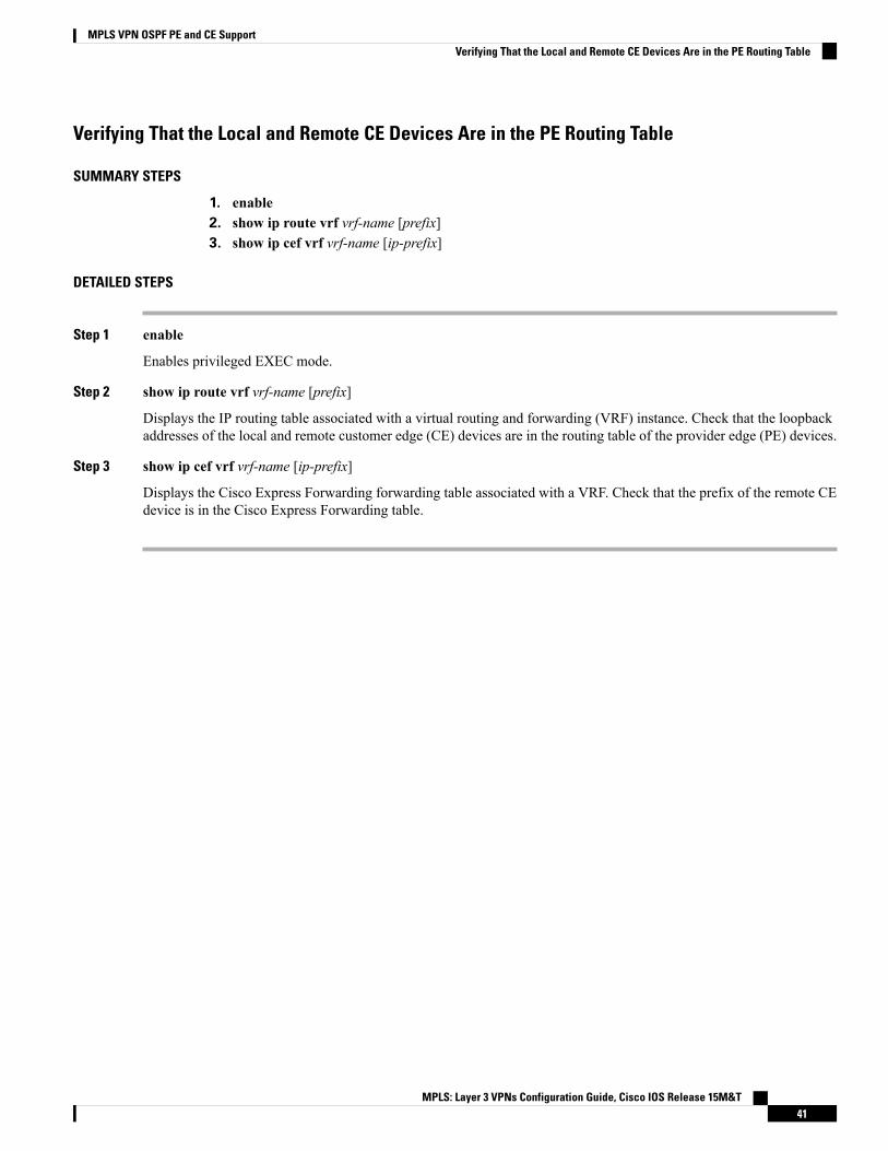
Verifying That the Local and Remote CE Devices Are in the PE Routing Table
SUMMARY STEPS
1. enable2. show ip route vrf vrf-name [prefix]3. show ip cef vrf vrf-name [ip-prefix]
DETAILED STEPS
Step 1 enable
Enables privileged EXEC mode.
Step 2 show ip route vrf vrf-name [prefix]
Displays the IP routing table associated with a virtual routing and forwarding (VRF) instance. Check that the loopbackaddresses of the local and remote customer edge (CE) devices are in the routing table of the provider edge (PE) devices.
Step 3 show ip cef vrf vrf-name [ip-prefix]
Displays the Cisco Express Forwarding forwarding table associated with a VRF. Check that the prefix of the remote CEdevice is in the Cisco Express Forwarding table.
MPLS: Layer 3 VPNs Configuration Guide, Cisco IOS Release 15M&T41
MPLS VPN OSPF PE and CE SupportVerifying That the Local and Remote CE Devices Are in the PE Routing Table

Configuration Examples for MPLS VPN OSPF PE and CE Support
Example: Configuring an MPLS VPN Using OSPFCE ConfigurationPE Configuration
ip cefmpls ldp router-id Loopback0 forcempls label protocol ldp!interface Loopback0ip address 10.0.0.9 255.255.255.255!interface FastEthernet0/0/0ip address 34.0.0.1 255.0.0.0no cdp enable!router ospf 1000log-adjacency-changesauto-cost reference-bandwidth 1000redistribute connected subnetsnetwork 34.0.0.0 0.255.255.255 area1000network 10.0.0.0 0.0.0.0 area 1000
ip vrf vpn1rd 100:1route-target export 100:1route-target import 100:1!ip cefmpls ldp router-id Loopback0 forcempls label protocol ldp!interface Loopback0ip address 10.0.0.1 255.255.255.255!interface FastEthernet0/0/0ip vrf forwarding vpn1ip address 34.0.0.2 255.0.0.0no cdp enable!router ospf 1000 vrf vpn1log-adjacency-changesredistribute bgp 100 metric-type 1 subnetsnetwork 10.0.0.13 0.0.0.0 area 10000network 34.0.0.0 0.255.255.255 area 10000!router bgp 100no synchronizationbgp log-neighbor changesneighbor 10.0.0.3 remote-as 100neighbor 10.0.0.3 update-source Loopback0no auto-summary!address-family vpnv4neighbor 10.0.0.3 activateneighbor 10.0.0.3 send-community extendedbgp scan-time import 5exit-address-family!address-family ipv4 vrf vpn1redistribute connectedredistribute ospf 1000 match internal external 1external 2no auto-summaryno synchronizationexit-address-family
MPLS: Layer 3 VPNs Configuration Guide, Cisco IOS Release 15M&T42
MPLS VPN OSPF PE and CE SupportConfiguration Examples for MPLS VPN OSPF PE and CE Support

Additional ReferencesRelated Documents
Document TitleRelated Topic
Cisco Master Command List, All ReleasesCisco IOS commands
Cisco IOSMultiprotocol Label Switching CommandReference
MPLS and MPLS applications commands
Standards and RFCs
TitleStandard/RFC
Using a Link State Advertisement (LSA) Options Bitto Prevent Looping in BGP/MPLS IP Virtual PrivateNetworks (VPNs)
RFC 4576
Technical Assistance
LinkDescription
http://www.cisco.com/cisco/web/support/index.htmlTheCisco Support andDocumentationwebsite providesonline resources to download documentation, software,and tools. Use these resources to install and configurethe software and to troubleshoot and resolve technicalissues with Cisco products and technologies. Access tomost tools on the Cisco Support and Documentationwebsite requires a Cisco.com user ID and password.
Feature Information for MPLS VPN OSPF PE and CE SupportThe following table provides release information about the feature or features described in this module. Thistable lists only the software release that introduced support for a given feature in a given software releasetrain. Unless noted otherwise, subsequent releases of that software release train also support that feature.
Use Cisco Feature Navigator to find information about platform support and Cisco software image support.To access Cisco Feature Navigator, go to www.cisco.com/go/cfn. An account on Cisco.com is not required.
MPLS: Layer 3 VPNs Configuration Guide, Cisco IOS Release 15M&T43
MPLS VPN OSPF PE and CE SupportAdditional References

Table 3: Feature Information for MPLS VPN OSPF PE and CE Support
Feature InformationReleasesFeature Name
The MPLS VPN OSPF PE and CESupport feature allows serviceproviders to configure OpenShortest Path First (OSPF) betweenprovider edge (PE) and customeredge (CE) devices in aMultiprotocol Label Switching(MPLS) virtual private network(VPN).
In Cisco IOS Release 12.0(5)T, thisfeature was introduced.
In Cisco IOS Release 12.0(11)ST,12.0(21)ST, 12.2(17b)SXA, and12.2(28)SB, this feature wasintegrated.
In Cisco IOS XE Release 2.1, thisfeature was implemented on CiscoASR 1000 Series Routers.
No commands were introduced ormodified.
12.0(5)T
12.0(11)ST
12.0(21)ST
12.2(17b)SXA
12.2(28)SB
Cisco IOS XE Release 2.1
MPLS VPN OSPF PE and CESupport
MPLS: Layer 3 VPNs Configuration Guide, Cisco IOS Release 15M&T44
MPLS VPN OSPF PE and CE SupportFeature Information for MPLS VPN OSPF PE and CE Support

C H A P T E R 4MPLS VPN Support for EIGRP Between PE andCE
The MPLS VPN Support for EIGRP Between PE and CE feature allows service providers to configure theEnhanced Interior Gateway Routing Protocol (EIGRP) between provider edge (PE) and customer edge (CE)devices in a Multiprotocol Label Switching (MPLS) virtual private network (VPN) and offer MPLS VPNservices to those customers that require native support for EIGRP. An MPLS VPN consists of a set of sitesthat are interconnected by an MPLS provider core network. At each customer site, one or more CE devicesattach to one or more PE devices.
• Finding Feature Information, on page 45• Prerequisites for MPLS VPN Support for EIGRP Between PE and CE, on page 45• Information About MPLS VPN Support for EIGRP Between PE and CE, on page 46• How to Configure MPLS VPN Support for EIGRP Between PE and CE, on page 46• Configuration Examples for MPLS VPN Support for EIGRP Between PE and CE, on page 52• Additional References, on page 54• Feature Information for MPLS VPN Support for EIGRP Between PE and CE, on page 54
Finding Feature InformationYour software release may not support all the features documented in this module. For the latest caveats andfeature information, see Bug Search Tool and the release notes for your platform and software release. Tofind information about the features documented in this module, and to see a list of the releases in which eachfeature is supported, see the feature information table.
Use Cisco Feature Navigator to find information about platform support and Cisco software image support.To access Cisco Feature Navigator, go to www.cisco.com/go/cfn. An account on Cisco.com is not required.
Prerequisites for MPLS VPN Support for EIGRP Between PE andCE
• Configure MPLS Layer 3 VPNs.
• Configure the Border Gateway Protocol (BGP) in the network core.
MPLS: Layer 3 VPNs Configuration Guide, Cisco IOS Release 15M&T45
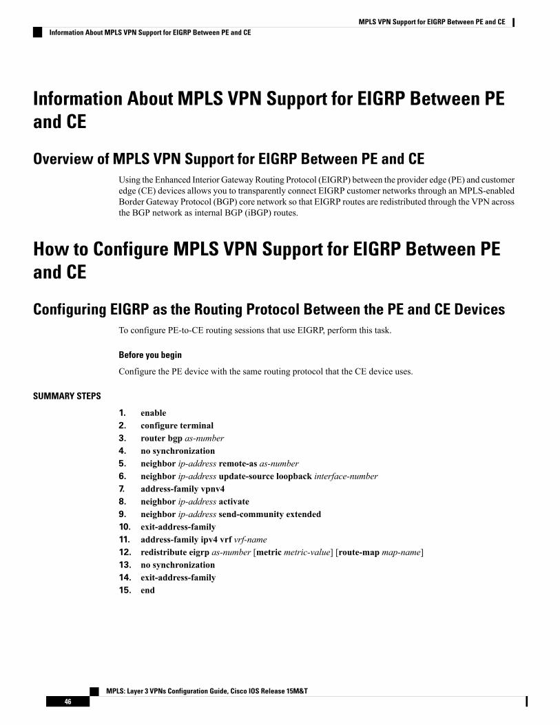
Information About MPLS VPN Support for EIGRP Between PEand CE
Overview of MPLS VPN Support for EIGRP Between PE and CEUsing the Enhanced Interior Gateway Routing Protocol (EIGRP) between the provider edge (PE) and customeredge (CE) devices allows you to transparently connect EIGRP customer networks through an MPLS-enabledBorder Gateway Protocol (BGP) core network so that EIGRP routes are redistributed through the VPN acrossthe BGP network as internal BGP (iBGP) routes.
How to Configure MPLS VPN Support for EIGRP Between PEand CE
Configuring EIGRP as the Routing Protocol Between the PE and CE DevicesTo configure PE-to-CE routing sessions that use EIGRP, perform this task.
Before you begin
Configure the PE device with the same routing protocol that the CE device uses.
SUMMARY STEPS
1. enable2. configure terminal3. router bgp as-number4. no synchronization5. neighbor ip-address remote-as as-number6. neighbor ip-address update-source loopback interface-number7. address-family vpnv48. neighbor ip-address activate9. neighbor ip-address send-community extended10. exit-address-family11. address-family ipv4 vrf vrf-name12. redistribute eigrp as-number [metric metric-value] [route-map map-name]13. no synchronization14. exit-address-family15. end
MPLS: Layer 3 VPNs Configuration Guide, Cisco IOS Release 15M&T46
MPLS VPN Support for EIGRP Between PE and CEInformation About MPLS VPN Support for EIGRP Between PE and CE

DETAILED STEPS
PurposeCommand or Action
Enables privileged EXEC mode.enableStep 1
Example: • Enter your password if prompted.
Device> enable
Enters global configuration mode.configure terminal
Example:
Step 2
Device# configure terminal
Enters router configuration mode, and creates a BGProuting process.
router bgp as-number
Example:
Step 3
Device(config)# router bgp 10
Configures BGP to send advertisements without waitingto synchronize with the IGP.
no synchronization
Example:
Step 4
Device(config-router)# no synchronization
Establishes peering with the specified neighbor or peergroup.
neighbor ip-address remote-as as-number
Example:
Step 5
• In this step, you are establishing an iBGP session withthe PE device that is connected to the CE device atthe other CE site.
Device(config-router)# neighbor 10.0.0.1 remote-as10
Configures BGP to use any operational interface for TCPconnections.
neighbor ip-address update-source loopbackinterface-number
Step 6
Example: • This configuration step is not required. However, theBGP routing process will be less susceptible to theeffects of interface or link flapping.Device(config-router)# neighbor 10.0.0.1
update-source loopback 0
Enters address family configuration mode for configuringrouting sessions that use standard IPv4 address prefixes,such as BGP, RIP, and static routing sessions.
address-family vpnv4
Example:
Device(config-router)# address-family vpnv4
Step 7
Establishes peering with the specified neighbor or peergroup.
neighbor ip-address activate
Example:
Step 8
• In this step, you are activating the exchange of VPNv4routing information between the PE devices.Device(config-router-af)# neighbor 10.0.0.1
activate
MPLS: Layer 3 VPNs Configuration Guide, Cisco IOS Release 15M&T47
MPLS VPN Support for EIGRP Between PE and CEConfiguring EIGRP as the Routing Protocol Between the PE and CE Devices

PurposeCommand or Action
Configures the local device to send extended communityattribute information to the specified neighbor.
neighbor ip-address send-community extended
Example:
Step 9
• This step is required for the exchange of EIGRPextended community attributes.Device(config-router-af)# neighbor 10.0.0.1
send-community extended
Exits address family configuration mode and enters routerconfiguration mode.
exit-address-family
Example:
Step 10
Device(config-router-af)# exit-address-family
Configures an IPv4 address family for the EIGRP VRFand enters address family configuration mode.
address-family ipv4 vrf vrf-name
Example:
Step 11
• An address-family VRF needs to be configured foreach EIGRP VRF that runs between the PE and CEdevices.
Device(config-router)# address-family ipv4 vrfRED
Redistributes the EIGRP VRF into BGP.redistribute eigrp as-number [metric metric-value][route-map map-name]
Step 12
• The autonomous system number from the CE networkis configured in this step.Example:
Device(config-router-af)# redistribute eigrp 101
Configures BGP to send advertisements without waitingto synchronize with the IGP.
no synchronization
Example:
Step 13
Device(config-router-af)# no synchronization
Exits address family configuration mode and enters routerconfiguration mode.
exit-address-family
Example:
Step 14
Device(config-router-af)# exit-address-family
Exits router configuration mode and enters privilegedEXEC mode.
end
Example:
Step 15
Device(config-router)# end
Configuring EIGRP Redistribution in the MPLS VPNPerform this task on every PE device that provides VPN services to enable EIGRP redistribution in the MPLSVPN.
MPLS: Layer 3 VPNs Configuration Guide, Cisco IOS Release 15M&T48
MPLS VPN Support for EIGRP Between PE and CEConfiguring EIGRP Redistribution in the MPLS VPN

Before you begin
Themetric must be configured for routes from external EIGRP autonomous systems and non-EIGRP networksbefore these routes can be redistributed into an EIGRP CE device. The metric can be configured in theredistribute statement using the redistribute (IP) command or can be configured with the default-metric(EIGRP) command. If an external route is received from another EIGRP autonomous system or a non-EIGRPnetwork without a configured metric, the route will not be advertised to the CE device.
Redistribution between native EIGRP VRFs is not supported. This is designed behavior.Note
SUMMARY STEPS
1. enable2. configure terminal3. router eigrp as-number4. address-family ipv4 [multicast | unicast | vrf vrf-name]5. network ip-address wildcard-mask6. redistribute bgp {as-number} [metric bandwidth delay reliability load mtu] [route-map map-name]7. autonomous-system as-number8. exit-address-family9. end
DETAILED STEPS
PurposeCommand or Action
Enables privileged EXEC mode.enableStep 1
Example: • Enter your password if prompted.
Device> enable
Enters global configuration mode.configure terminal
Example:
Step 2
Device# configure terminal
Enters router configuration mode and creates an EIGRProuting process.
router eigrp as-number
Example:
Step 3
• The EIGRP routing process for the PE device is createdin this step.Device(config)# router eigrp 1
Enters address-family configuration mode and creates aVRF.
address-family ipv4 [multicast | unicast | vrf vrf-name]
Example:
Step 4
• The VRF name must match the VRF name that wascreated in the previous section.Device(config-router)# address-family ipv4 vrf RED
Specifies the network for the VRF.network ip-address wildcard-maskStep 5
MPLS: Layer 3 VPNs Configuration Guide, Cisco IOS Release 15M&T49
MPLS VPN Support for EIGRP Between PE and CEConfiguring EIGRP Redistribution in the MPLS VPN

PurposeCommand or Action
Example: • The network statement is used to identify whichinterfaces to include in EIGRP. The VRF must be
Device(config-router-af)# network 172.16.0.00.0.255.255
configured with addresses that fall within thewildcard-mask range of the network statement.
Redistributes BGP into the EIGRP.redistribute bgp {as-number} [metric bandwidth delayreliability load mtu] [route-map map-name]
Step 6
• The autonomous system number and metric of theBGP network are configured in this step. BGP mustExample:be redistributed into EIGRP for the CE site to accept
Device(config-router-af)# redistribute bgp 10metric 10000 100 255 1 1500
the BGP routes that carry the EIGRP information. Ametric must also be specified for the BGP network andis configured in this step.
Specifies the autonomous system number of the EIGRPnetwork for the customer site.
autonomous-system as-number
Example:
Step 7
Device(config-router-af)# autonomous-system 101
Exits address family configuration mode and enters routerconfiguration mode.
exit-address-family
Example:
Step 8
Device(config-router-af)# exit-address-family
Exits router configurationmode and enters privileged EXECmode.
end
Example:
Step 9
Device(config-router)# end
Verifying Connectivity Between MPLS Virtual Private Network SitesTo verify that the local and remote customer edge (CE) devices can communicate across the MultiprotocolLabel Switching (MPLS) core, perform the following tasks:
Verifying IP Connectivity from CE Device to CE Device Across the MPLS Core
SUMMARY STEPS
1. enable2. ping [protocol] {host-name | system-address}3. trace [protocol] [destination]4. show ip route [ip-address [mask] [longer-prefixes]] | protocol [process-id]] | [list [access-list-name |
access-list-number]
MPLS: Layer 3 VPNs Configuration Guide, Cisco IOS Release 15M&T50
MPLS VPN Support for EIGRP Between PE and CEVerifying Connectivity Between MPLS Virtual Private Network Sites
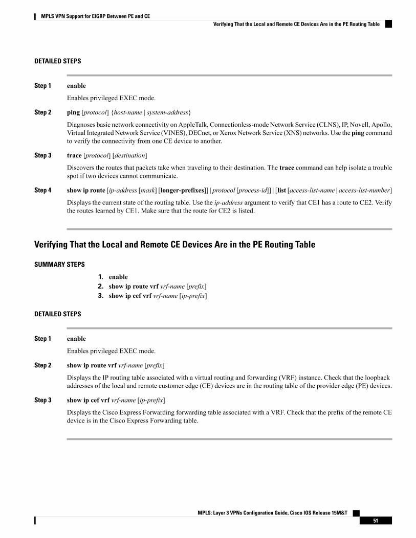
DETAILED STEPS
Step 1 enable
Enables privileged EXEC mode.
Step 2 ping [protocol] {host-name | system-address}
Diagnoses basic network connectivity on AppleTalk, Connectionless-modeNetwork Service (CLNS), IP, Novell, Apollo,Virtual Integrated Network Service (VINES), DECnet, or Xerox Network Service (XNS) networks. Use the ping commandto verify the connectivity from one CE device to another.
Step 3 trace [protocol] [destination]
Discovers the routes that packets take when traveling to their destination. The trace command can help isolate a troublespot if two devices cannot communicate.
Step 4 show ip route [ip-address [mask] [longer-prefixes]] | protocol [process-id]] | [list [access-list-name | access-list-number]
Displays the current state of the routing table. Use the ip-address argument to verify that CE1 has a route to CE2. Verifythe routes learned by CE1. Make sure that the route for CE2 is listed.
Verifying That the Local and Remote CE Devices Are in the PE Routing Table
SUMMARY STEPS
1. enable2. show ip route vrf vrf-name [prefix]3. show ip cef vrf vrf-name [ip-prefix]
DETAILED STEPS
Step 1 enable
Enables privileged EXEC mode.
Step 2 show ip route vrf vrf-name [prefix]
Displays the IP routing table associated with a virtual routing and forwarding (VRF) instance. Check that the loopbackaddresses of the local and remote customer edge (CE) devices are in the routing table of the provider edge (PE) devices.
Step 3 show ip cef vrf vrf-name [ip-prefix]
Displays the Cisco Express Forwarding forwarding table associated with a VRF. Check that the prefix of the remote CEdevice is in the Cisco Express Forwarding table.
MPLS: Layer 3 VPNs Configuration Guide, Cisco IOS Release 15M&T51
MPLS VPN Support for EIGRP Between PE and CEVerifying That the Local and Remote CE Devices Are in the PE Routing Table

Configuration Examples for MPLS VPN Support for EIGRPBetween PE and CE
Example: Configuring an MPLS VPN Using EIGRPCE ConfigurationPE Configuration
ip cef
mpls ldp router-id Loopback0 forcempls label protocol ldp!interface Loopback0ip address 10.0.0.9 255.255.255.255!interface FastEthernet0/0/0ip address 34.0.0.1 255.0.0.0no cdp enable!router eigrp 1000network 34.0.0.0auto-summary
MPLS: Layer 3 VPNs Configuration Guide, Cisco IOS Release 15M&T52
MPLS VPN Support for EIGRP Between PE and CEConfiguration Examples for MPLS VPN Support for EIGRP Between PE and CE
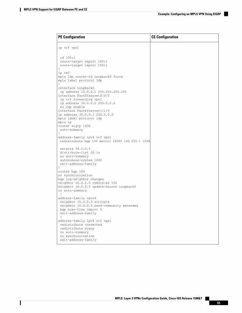
CE ConfigurationPE Configuration
ip vrf vpn1
rd 100:1route-target export 100:1route-target import 100:1!ip cefmpls ldp router-id Loopback0 forcempls label protocol ldp!interface Loopback0ip address 10.0.0.1 255.255.255.255interface FastEthernet0/0/0ip vrf forwarding vpn1ip address 34.0.0.2 255.0.0.0no cdp enableinterface FastEthernet1/1/0ip address 30.0.0.1 255.0.0.0mpls label protocol ldpmpls iprouter eigrp 1000auto-summary!address-family ipv4 vrf vpn1redistribute bgp 100 metric 10000 100 255 1 1500
network 34.0.0.0distribute-list 20 inno auto-summaryautonomous-system 1000exit-address-family!router bgp 100no synchronizationbgp log-neighbor changesneighbor 10.0.0.3 remote-as 100neighbor 10.0.0.3 update-source Loopback0no auto-summary!address-family vpnv4neighbor 10.0.0.3 activateneighbor 10.0.0.3 send-community extendedbgp scan-time import 5exit-address-family!address-family ipv4 vrf vpn1redistribute connectedredistribute eigrpno auto-summaryno synchronizationexit-address-family
MPLS: Layer 3 VPNs Configuration Guide, Cisco IOS Release 15M&T53
MPLS VPN Support for EIGRP Between PE and CEExample: Configuring an MPLS VPN Using EIGRP
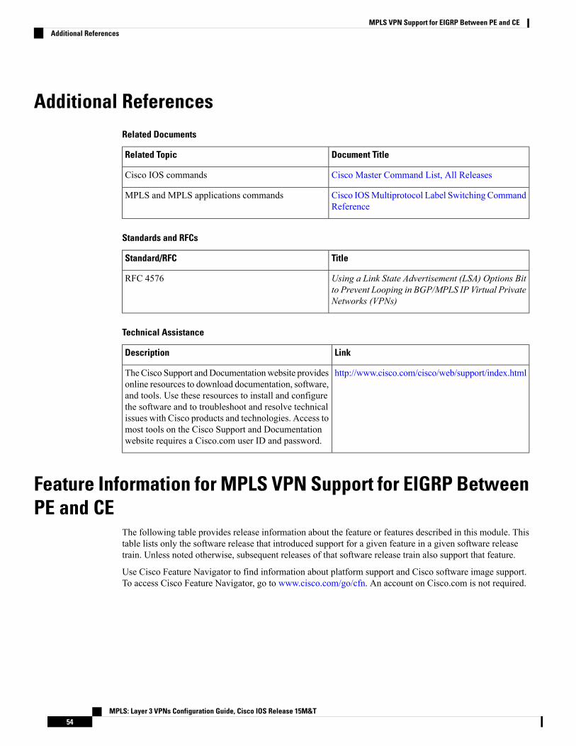
Additional ReferencesRelated Documents
Document TitleRelated Topic
Cisco Master Command List, All ReleasesCisco IOS commands
Cisco IOSMultiprotocol Label Switching CommandReference
MPLS and MPLS applications commands
Standards and RFCs
TitleStandard/RFC
Using a Link State Advertisement (LSA) Options Bitto Prevent Looping in BGP/MPLS IP Virtual PrivateNetworks (VPNs)
RFC 4576
Technical Assistance
LinkDescription
http://www.cisco.com/cisco/web/support/index.htmlTheCisco Support andDocumentationwebsite providesonline resources to download documentation, software,and tools. Use these resources to install and configurethe software and to troubleshoot and resolve technicalissues with Cisco products and technologies. Access tomost tools on the Cisco Support and Documentationwebsite requires a Cisco.com user ID and password.
Feature Information for MPLS VPN Support for EIGRP BetweenPE and CE
The following table provides release information about the feature or features described in this module. Thistable lists only the software release that introduced support for a given feature in a given software releasetrain. Unless noted otherwise, subsequent releases of that software release train also support that feature.
Use Cisco Feature Navigator to find information about platform support and Cisco software image support.To access Cisco Feature Navigator, go to www.cisco.com/go/cfn. An account on Cisco.com is not required.
MPLS: Layer 3 VPNs Configuration Guide, Cisco IOS Release 15M&T54
MPLS VPN Support for EIGRP Between PE and CEAdditional References

Table 4: Feature Information for MPLS VPN Support for EIGRP Between PE and CE
Feature InformationReleasesFeature Name
The MPLS VPN Support forEIGRPBetween PE and CE featureallows service providers toconfigure the Enhanced InteriorGatewayRouting Protocol (EIGRP)between provider edge (PE) andcustomer edge (CE) devices in aMultiprotocol Label Switching(MPLS) virtual private network(VPN) and offer MPLS VPNservices to those customers thatrequire native support for EIGRP.
In Cisco IOS Release 12.0(22)S,this feature was introduced.
In Cisco IOS Release 12.2(15)T,12.2(18)S, 12.2(18)SXD,12.2(27)SBB, and 12.3(2)T, thisfeature was integrated.
In Cisco IOS XE Release 2.1, thisfeature was implemented on CiscoASR 1000 Series Routers.
No commands were introduced ormodified.
12.0(22)S
12.2(15)T
12.2(18)S
12.2(18)SXD
12.2(27)SBB
12.3(2)T
Cisco IOS XE Release 2.1
MPLS VPN Support for EIGRPBetween PE and CE
MPLS: Layer 3 VPNs Configuration Guide, Cisco IOS Release 15M&T55
MPLS VPN Support for EIGRP Between PE and CEFeature Information for MPLS VPN Support for EIGRP Between PE and CE
MPLS: Layer 3 VPNs Configuration Guide, Cisco IOS Release 15M&T56
MPLS VPN Support for EIGRP Between PE and CEFeature Information for MPLS VPN Support for EIGRP Between PE and CE

C H A P T E R 5IPv6 VPN over MPLS
The Border Gateway Protocol over Multiprotocol Label Switching VPN feature is an implementation of theprovider edge (PE)-based Virtual Private Network (VPN) model. In principle, there is no difference betweenIPv4 and IPv6 VPNs. In both IPv4 and IPv6, multiprotocol Border Gateway Protocol (BGP) is the center ofthe Multiprotocol Label Switching (MPLS) VPN for IPv6 (VPNv6) architecture. It is used to distribute IPv6routes over the service provider backbone, using the same procedures to work with overlapping addresses,redistribution policies, and scalability issues.
• Finding Feature Information, on page 57• Prerequisites for IPv6 VPN over MPLS, on page 57• Restrictions for IPv6 VPN over MPLS, on page 58• Information About IPv6 VPN over MPLS, on page 58• How to Configure IPv6 VPN over MPLS, on page 64• Configuration Examples for IPv6 VPN over MPLS, on page 101• Additional References, on page 107• Glossary, on page 107
Finding Feature InformationYour software release may not support all the features documented in this module. For the latest caveats andfeature information, see Bug Search Tool and the release notes for your platform and software release. Tofind information about the features documented in this module, and to see a list of the releases in which eachfeature is supported, see the feature information table.
Use Cisco Feature Navigator to find information about platform support and Cisco software image support.To access Cisco Feature Navigator, go to www.cisco.com/go/cfn. An account on Cisco.com is not required.
Prerequisites for IPv6 VPN over MPLSYour network must be running the following services before you configure IPv6 VPN operation:
• Multiprotocol Label Switching (MPLS) in provider backbone devices
• MPLS with Virtual Private Network (VPN) code in provider devices with VPN provider edge (PE)devices
• Border Gateway Protocol (BGP) in all devices providing a VPN service
MPLS: Layer 3 VPNs Configuration Guide, Cisco IOS Release 15M&T57

• Cisco Express Forwarding switching in every MPLS-enabled device
• Class of Service (CoS) feature
Restrictions for IPv6 VPN over MPLSIPv6 VPN over MPLS (6VPE) supports a Multiprotocol Label Switching (MPLS) IPv4-signaled core. AnMPLS IPv6-signaled core is not supported.
Information About IPv6 VPN over MPLS
IPv6 VPN over MPLS OverviewMultiprotocol Border Gateway Protocol (BGP) is the center of the Multiprotocol Label Switching (MPLS)IPv6 Virtual Private Network (VPN) architecture in both IPv4 and IPv6. It is used to distribute IPv6 routesover the service provider backbone, using the same procedures to work with overlapping addresses,redistribution policies, and scalability issues.
Although IPv6 should not have overlapping address space, IPv6 addresses are prepended with a routedistinguisher (RD). A network layer reachability information (NLRI) 3-tuple format (which contains length,IPv6 prefix, and label) is defined to distribute these routes using multiprotocol BGP. The extended communityattribute (for example, the route target) is used to control redistribution of routing information by taggingexported routes and filtering imported ones.
For scalability, route reflectors can be used to concentrate routing paths and avoid a full provider edge (PE)mesh. BGP features in IPv6, such as route refresh, automatic route filtering, and outbound route filtering, helpreduce the number of routes held in each PE. This document focuses on the following differences betweenIPv6 and IPv4:
• Creation of a newmultiprotocol BGP IPv6 VPN address family and specification of a IPv6 VPN addressformat
• Specification of a new IPv6 VPN NLRI
• Specification of BGP next-hop encoding when the device has an IPv4-based MPLS core
Some IPv6 VPN features, such as interprovider and Carrier Supporting Carrier (CSC) topologies, are specificto BGP-MPLS IPv6 VPN. Others, such as the link between Autonomous SystemBoundary Routers (ASBRs),might support IPv4 only, IPv6 only, or both, regardless of the address family being transported.
Addressing Considerations for IPv6 VPN over MPLSRegardless of the Virtual Private Network (VPN) model deployed, an addressing plan must be defined forthe VPN that allows hosts to communicate with other sites using one site within one VPN, as well as withpublic resources.
VPN IPv4 sites often use private addressing for their addressing plan. These addresses do not need to beregistered, and they are not routable on the public network. Whenever a host within a private site needs to
MPLS: Layer 3 VPNs Configuration Guide, Cisco IOS Release 15M&T58
IPv6 VPN over MPLSRestrictions for IPv6 VPN over MPLS

access a public domain, it goes through a device that finds a public address on its behalf. With IPv4, this canbe a network address translator or an application proxy.
Given the larger address space available with IPv6, the easiest approach to IPv6 addressing is to use IPv6global addresses for the private addressing plan. Another approach is to use unique local addresses (ULAs).ULAs are easy to filter at site boundaries based on their scope. ULAs are also Internet service provider(ISP)-independent and can be used for communications inside a site without any permanent or intermittentInternet connectivity.
In IPv6 VPN over MPLS (6VPE), ULAs are treated as regular global addresses. The device configurationfilters ULA prefixes to prevent them from appearing in the public domain. Link-local addresses on the peerwill not be announced by Border Gateway Protocol (BGP) (IPv6 or IPv6 VPN) speakers.
A host within a private site that needs to access a public domain can do so through an IPv6 application proxy(such as a web proxy for accessing web pages), which accesses the public resource on the host’s behalf witha global routable address, or the host can use a public address of its own. In the latter case, if ULAs have beendeployed, the IPv6 host also is configured with a routable global address. A source address selection algorithmis used to select one or the other, based on the destination address.
Basic IPv6 VPN over MPLS FunctionalityIPv6 VPN over MPLS (6VPE) takes advantage of the coexistence between IPv6 and IPv4 by leveraging anexistent Multiprotocol Label Switching (MPLS) IPv4 core network:
IPv6 VPN Architecture OverviewThe figure below illustrates the important aspects of the IPv6 Virtual Private Network (VPN) architecture.Figure 3: Simple IPv6 VPN Architecture
The customer edge (CE) devices are connected to the provider’s backbone using provider edge (PE) devices.The PE devices are connected using provider (P1 and P2 in the figure above) devices. The provider (P) devicesare unaware of VPN routes, and, in the case of IPv6 over MPLS (6VPE), might support only IPv4. Only PEdevices perform VPN-specific tasks. For 6VPE, the PE devices are dual-stack (IPv4 and IPv6) devices.
The routing component of the VPN operation is divided into core routing and edge routing. Core routing,which involves PE devices and P devices, typically is performed by an IPv4 Interior Gateway Protocol (IGP)such as Open Shortest Path First (OSPF) or Intermediate System-to-Intermediate System (IS-IS). In the figureabove, the IGP distributes only routes internal to the provider’s autonomous system. The core routing enablesconnectivity among P and PE devices.
MPLS: Layer 3 VPNs Configuration Guide, Cisco IOS Release 15M&T59
IPv6 VPN over MPLSBasic IPv6 VPN over MPLS Functionality

Edge routing takes place in two directions: routing between PE pairs and routing between a PE and a CE.Routing between PE pairs is achieved using multiprotocol internal BGP (iBGP) using the IPv6 VPN addressfamily. This method distributes routes learned from CEs through PE-CE routing, using appropriate routeexport policies at the ingress PE device and appropriate route import policies at the egress PE device.
Routing between the CE and its PE is achieved using a routing protocol that is VPN routing and forwarding(VRF) aware. Static routes, external BGP (eBGP), and Enhanced Interior Gateway Routing Protocol (EIGRP)are VRF-instance aware. In the figure above, eBGP is used between the CE (CE1) and the PE (PE1). At thesame time, the CE runs an IPv6 IGP within the VPN site (site1 in the figure above). The CE redistributes IGProutes into multiprotocol-eBGP address family IPv6. At the PE, these routes are installed in the VRF namedvrf1, and forwarded to the remote PEs (PE2 in the figure above), according to export policies defined for thisVRF.
IPv6 VPN Next HopWhen the device announces a prefix using theMP_REACH_NLRI attribute, theMultiprotocol Border GatewayProtocol (MP-BGP) running on one provider edge (PE) inserts a BGP next hop in the update message sent toa remote PE. This next hop is either propagated from the received update (for instance, if the PE is a routereflector), or it is the address of the PE sending the update message (the egress PE).
For the IPv6 Virtual Private Network (VPN) address family, the next hop must be an IPv6 VPN address,regardless of the nature of the network between the PE speakers. Because the route distinguisher (RD) hasno significance (the address is not part of any VPN), it is set to 0. If the provider network is a native IPv6network, the remaining part of the next hop is the IPv6 address of the egress PE. Otherwise, it is an IPv4address used as an IPv6-mapped address (for example, ::FFFF:IPv4-address).
MPLS ForwardingWhen it receives IPv6 traffic from one customer site, the ingress provider edge (PE) device usesMultiprotocolLabel Switching (MPLS) to tunnel IPv6 Virtual Private Network (VPN) packets over the backbone towardthe egress PE device identified as the Border Gateway Protocol (BGP) next hop. The ingress PE deviceprepends the IPv6 packets with the outer and inner labels before putting the packet on the egress interface.
Under normal operation, a provider (P) device along the forwarding path does not look inside the frame beyondthe first label. The provider (P) device either swaps the incoming label with an outgoing one or removes theincoming label if the next device is a PE device. Removing the incoming label is called penultimate hoppopping. The remaining label (BGP label) is used to identify the egress PE interface toward the customer site.The label also hides the protocol version (IPv6) from the last P device, which it would otherwise need toforward an IPv6 packet.
A P device is ignorant of the IPv6 VPN routes. The IPv6 header remains hidden under one or more MPLSlabels. When the P device receives an MPLS-encapsulated IPv6 packet that cannot be delivered, it has twooptions. If the P device is IPv6 aware, it exposes the IPv6 header, builds an Internet Control Message Protocol(ICMP) for IPv6 message, and sends the message, which is MPLS encapsulated, to the source of the originalpacket. If the P device is not IPv6 aware, it drops the packet.
VRF ConceptsA virtual routing and forwarding (VRF) entity works with a private customer-specific Routing InformationBase (RIB) and Forwarding Information Base (FIB). Although IPv4 and IPv6 routing tables are distinct, it isconvenient for the two protocols to share the same VRF for a specific customer.
IPv6 VPN customers are likely to be existing VPNv4 customers that are either deploying dual-stack hostsand devices or shadowing some of their IPv4 infrastructure with IPv6 nodes. Several deployment models are
MPLS: Layer 3 VPNs Configuration Guide, Cisco IOS Release 15M&T60
IPv6 VPN over MPLSIPv6 VPN Next Hop

possible. Some customers use separate logical interfaces for IPv4 and IPv6 and define separate VRFs on each.Although this approach provides flexibility to configure separate policies for IPv4 and IPv6, it prevents sharingthe same policy. Another approach, the multiprotocol VRF, keeps a single VRF on the provider edge-customeredge (PE-CE) interface, and enables it for IPv4, IPv6, or both. It is then possible to define common or separatepolicies for each IP version. With this approach, a VRF is better defined as the set of tables, interfaces, andpolicies found at the PE, and is used by sites of a particular VPN connected to this PE.
The figure below illustrates the multiprotocol VRF, in which the VRF named vrf1is enabled for both IPv4and IPv6 and is associated with two interfaces (IF1, IF2), two sets of tables (IPv4 RIB and FIB and IPv6 RIBand FIB), and a set of common or distinct policies.Figure 4: Multiprotocol VRF
IPv6 VPN ScalabilityProvider edge (PE)-based Virtual Private Networks (VPNs) such as Border Gateway Protocol-MultiprotocolLabel Switching (BGP-MPLS) IPv6 VPN scale better than customer edge (CE)-based VPNs. A networkdesigner must consider scaling when designing the network. The following points need to be considered:
• Routing table size, which includes the size of virtual routing and forwarding (VRF) tables and BGP tables
• Number of BGP sessions, which grows as a square number of PEs
Routing table size concerns occur with PEs that handle many customer sites. Not only do these PEs have oneRouting Information Base (RIB) and Forwarding Information Base (FIB) per connected customer, but alsothe PEs’ BGP tables, which total all entries from individual VRFs, grow accordingly. Another scalabilityproblem occurs when the number of PEs in the provider network grows beyond a certain level. Assumingthat a significant number of sites belonging to the same VPN are spread over many PEs, the number ofmultiprotocol BGP sessions may rapidly become prohibitive: (n -1) x n /2, where n is the number of PEs.
The following features are included in IPv6 VPN over MPLS:
• Route refresh and automatic route filtering—Limits the size of routing tables, because only routes importedinto a VRF are kept locally. When the import policy changes, a route refresh can be sent to query aretransmission of routing updates.
• Outbound route filtering (ORF)—Allows the ingress PE to advertise filters to the egress PE so thatupdates are not sent unnecessarily over the network.
MPLS: Layer 3 VPNs Configuration Guide, Cisco IOS Release 15M&T61
IPv6 VPN over MPLSIPv6 VPN Scalability

• Route reflectors—Route reflectors (RRs) are internal BGP (iBGP) peers that propagate iBGP routeslearned from other iBGP peers. RRs are used to concentrate iBGP sessions.
Advanced IPv6 MPLS VPN FunctionalityAdvanced Multiprotocol Label Switching (MPLS) features such as accessing the Internet from a VirtualPrivate Network (VPN) for IPv4, multiautonomous-system backbones, and Carrier Supporting Carriers (CSCs)are generally the same for IPv6 as for IPv4. However, there are differences in addressing and in the way IPv6over MPLS (6VPE) operates over an IPv4 backbone.
The following sections describe concepts for advanced IPv6 MPLS VPN functionality:
Internet AccessMost Virtual Private Network (VPN) sites require access to the Internet. RFC 4364 describes a set of modelsfor enabling IPv4 and IPv6 VPN access to the Internet. In one model, one interface is used by the customeredge (CE) to connect to the Internet and a different one to connect to the virtual routing and forwarding (VRF)instance. Another model is in which all Internet routes are redistributed into the VRF; however, this approachhas the disadvantage of requiring the Internet routes be replicated in each VRF.
In one scenario, a static route is inserted into the VRF table, with a next hop that points to the Internet gatewayfound in the IPv6 default table. The figure below illustrates this scenario, in which Internet access is providedto the customer in the VRF named vrf1.Figure 5: Internet Access Topology
A customer site that has access public resources over the Internet must be known by a public prefix. UnlikeIPv4, IPv6 does not offer a Network Address Translation (NAT) mechanism that translates private addressesinto public addresses when leaving the site boundaries. This implies that hosts within the site speak withpublic addresses and appear in the public domain.
For outbound traffic, the default route configured in the VRF table at ingress provider edge (PE1) directstraffic for destinations outside the VPN to the Internet gateway.
For inbound traffic, a route must exist at the Internet gateway to direct the traffic for a customer site via itsPE of attachment (PE1 in the figure above). This route can be distributed by the ingress PE (PE1) usingmultiprotocol internal Border Gateway Protocol (iBGP) (with the IPv6 address family configuration), so nospecific configuration is needed on a per-VPN PE basis at the Internet gateway. Nevertheless, for inboundtraffic at PE1, a route must exist in the default table for the customer site global prefix pointing to the VRFof the site.
MPLS: Layer 3 VPNs Configuration Guide, Cisco IOS Release 15M&T62
IPv6 VPN over MPLSAdvanced IPv6 MPLS VPN Functionality

Multiautonomous-System BackbonesThe problem of interprovider Virtual Private Networks (VPNs) is similar for IPv6 and IPv4, assuming thatIPv6 was deployed everywhere IPv4 was deployed.
In IPv6 deployments that cross autonomous system boundaries, providers may have to obtain a peering model,or work with the peering model put in place for VPNv4.
The figure below illustrates interprovider scenarios in IPv6 VPN.Figure 6: Interprovider Scenarios
Depending on the network protocol used between Autonomous System Boundary Routers (ASBRs), the threescenarios shown in the figure above can have several implementation options. For instance, scenario B, whichsuggests a multiprotocol external Border Gateway Protocol (eBGP) IPv6 VPN peering between ASBRs, coulduse either an IPv6 or an IPv4 link.
In scenario C, multihop multiprotocol eBGP redistributes IPv6 VPN routes across route reflectors in differentautonomous systems. Labeled IPv4 routes to the provider edge (PE) devices (in the IPv6 over MPLS case)need to be advertised across ASBRs so that a complete labeled switch path is set up end to end.
MPLS: Layer 3 VPNs Configuration Guide, Cisco IOS Release 15M&T63
IPv6 VPN over MPLSMultiautonomous-System Backbones

Carrier Supporting CarriersThe Carrier Supporting Carrier (CSC) feature provides Virtual Private Network (VPN) access to a customerservice provider, so this service needs to exchange routes and send traffic over the Internet service provider(ISP) Multiprotocol Label Switching (MPLS) backbone. The only difference from a regular provider edge(PE) is that it provides MPLS-to-MPLS forwarding on the CSC-customer edge (CE) to CSC-PE interface,rather than IP-to-MPLS forwarding.
The figure below highlights the two ISPs’ interface.Figure 7: CSC IPv6 over MPLS Configuration Example
How to Configure IPv6 VPN over MPLS
Configuring a Virtual Routing and Forwarding Instance for IPv6A virtual routing and forwarding (VRF) instance is an address family-independent object that can be enabledand configured for each of the supported address families. Configuring a VRF consists of the following threesteps:
• Configuring the address-family-independent part of the VRF
• Enabling and configuring IPv4 for the VRF
• Enabling and configuring IPv6 for the VRF
AVRF is given a name and a route distinguisher (RD). The RD is configured outside the context of the addressfamily, although the RD is used to distinguish overlapping addresses within the context of a particular BorderGateway Protocol (BGP) address family. Having separate RDs for IPv4 VPN addresses and IPv6 VPNaddresses does not matter. On Cisco devices, the RDs are the same in order to simplify configuration andVPN management.
Users can configure policies in common between IPv4 and IPv6 when not using an address family context.This feature is shared route targets (import and export), and it is useful in a migration scenario, where IPv4policies already are configured and IPv6 policies should be the same as the IPv4 policies.
The IPv4 and IPv6 address family can each be enabled and configured separately. Note that the route-targetpolicies entered at this level override global policies that may have been specified during addressfamily-independent configuration.
SUMMARY STEPS
1. enable
MPLS: Layer 3 VPNs Configuration Guide, Cisco IOS Release 15M&T64
IPv6 VPN over MPLSCarrier Supporting Carriers

2. configure terminal3. vrf definition vrf-name4. rd route-distinguisher5. route-target {import | export | both} route-target-ext-community6. address-family ipv4 [mdt |multicast | tunnel | unicast [vrf vrf-name] | vrf vrf-name]7. route-target {import | export | both} route-target-ext-community8. exit9. address-family ipv6 [vrf vrf-name] [unicast |multicast]10. route-target {import | export | both} route-target-ext-community
DETAILED STEPS
PurposeCommand or Action
Enables privileged EXEC mode.enableStep 1
Example: • Enter your password if prompted.
Device> enable
Enters global configuration mode.configure terminal
Example:
Step 2
Device# configure terminal
Configures a VPN VRF routing table and enters VRFconfiguration mode.
vrf definition vrf-name
Example:
Step 3
Device(config)# vrf definition vrf1
Specifies the RD for a VRF.rd route-distinguisher
Example:
Step 4
Device(config-vrf)# rd 100:1
Specifies the route target VPN extended communities forboth IPv4 and IPv6.
route-target {import | export | both}route-target-ext-community
Example:
Step 5
Device(config-vrf)# route target import 100:10
Enters address family configuration mode to configure arouting session using standard IPv4 address prefixes.
address-family ipv4 [mdt |multicast | tunnel | unicast[vrf vrf-name] | vrf vrf-name]
Example:
Step 6
Device(config)# address-family ipv4
Specifies the route target VPN extended communitiesspecific to IPv4.
route-target {import | export | both}route-target-ext-community
Example:
Step 7
MPLS: Layer 3 VPNs Configuration Guide, Cisco IOS Release 15M&T65
IPv6 VPN over MPLSConfiguring a Virtual Routing and Forwarding Instance for IPv6

PurposeCommand or Action
Device(config-vrf-af)# route target import 100:11
Exits address family configuration mode on this VRF.exit
Example:
Step 8
Device(config-vrf-af)# exit
Enters address family configuration mode for configuringrouting sessions such as BGP that use standard IPv6address prefixes.
address-family ipv6 [vrf vrf-name] [unicast |multicast]
Example:
Device(config-vrf)# address-family ipv6
Step 9
Specifies the route target VPN extended communitiesspecific to IPv6.
route-target {import | export | both}route-target-ext-community
Example:
Step 10
Device(config-vrf-af)# route target import 100:12
Binding a VRF to an InterfaceIn order to specify which interface belongs to which virtual routing and forwarding (VRF) instance, use thevrf forwarding command for both IPv4 and IPv6. An interface cannot belong to more than one VRF. Whenthe interface is bound to a VRF, previously configured addresses (IPv4 and IPv6) are removed, and they mustbe reconfigured.
SUMMARY STEPS
1. enable2. configure terminal3. interface type number4. vrf forwarding vrf-name5. ip address ip-address mask [secondary]6. ipv6 address {ipv6-address / prefix-length | prefix-name sub-bits/prefix-length
DETAILED STEPS
PurposeCommand or Action
Enables privileged EXEC mode.enableStep 1
Example: • Enter your password if prompted.
Device> enable
Enters global configuration mode.configure terminal
Example:
Step 2
MPLS: Layer 3 VPNs Configuration Guide, Cisco IOS Release 15M&T66
IPv6 VPN over MPLSBinding a VRF to an Interface
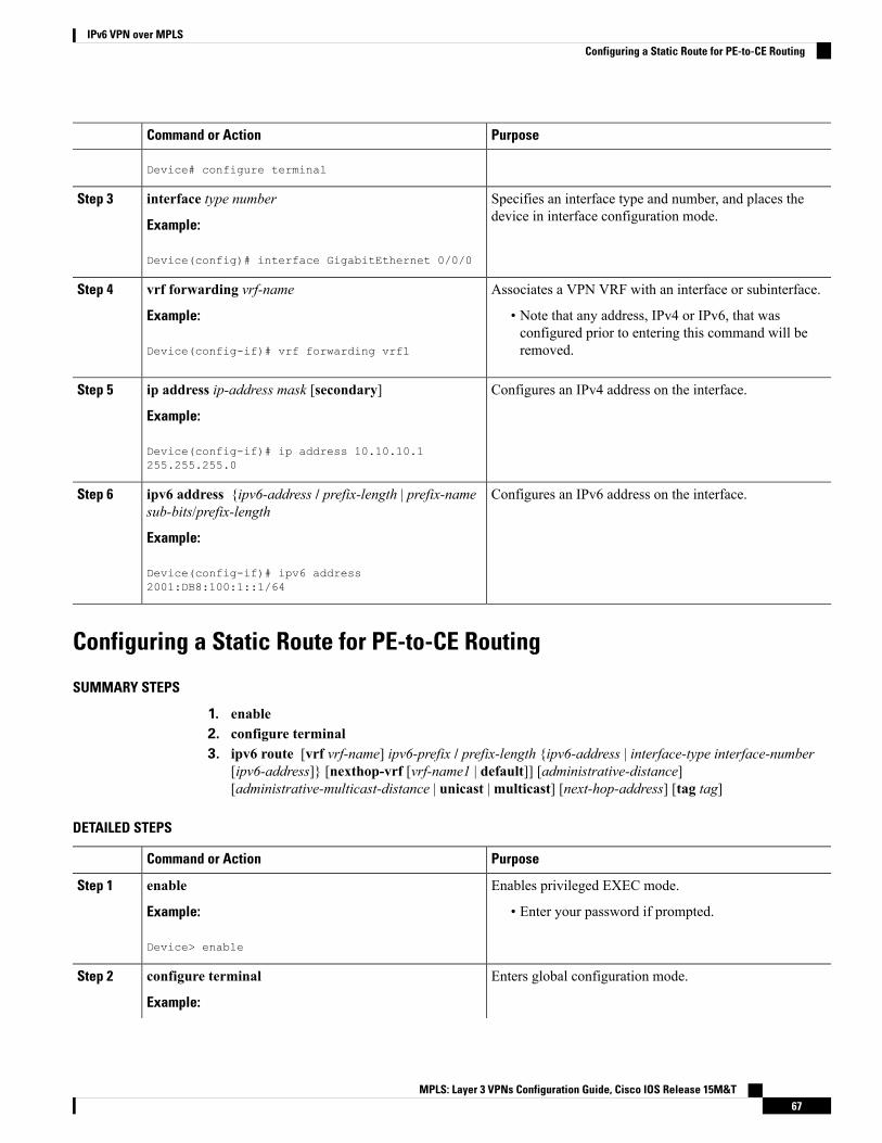
PurposeCommand or Action
Device# configure terminal
Specifies an interface type and number, and places thedevice in interface configuration mode.
interface type number
Example:
Step 3
Device(config)# interface GigabitEthernet 0/0/0
Associates a VPN VRF with an interface or subinterface.vrf forwarding vrf-nameStep 4
Example: • Note that any address, IPv4 or IPv6, that wasconfigured prior to entering this command will beremoved.Device(config-if)# vrf forwarding vrf1
Configures an IPv4 address on the interface.ip address ip-address mask [secondary]
Example:
Step 5
Device(config-if)# ip address 10.10.10.1255.255.255.0
Configures an IPv6 address on the interface.ipv6 address {ipv6-address / prefix-length | prefix-namesub-bits/prefix-length
Step 6
Example:
Device(config-if)# ipv6 address2001:DB8:100:1::1/64
Configuring a Static Route for PE-to-CE Routing
SUMMARY STEPS
1. enable2. configure terminal3. ipv6 route [vrf vrf-name] ipv6-prefix / prefix-length {ipv6-address | interface-type interface-number
[ipv6-address]} [nexthop-vrf [vrf-name1 | default]] [administrative-distance][administrative-multicast-distance | unicast |multicast] [next-hop-address] [tag tag]
DETAILED STEPS
PurposeCommand or Action
Enables privileged EXEC mode.enableStep 1
Example: • Enter your password if prompted.
Device> enable
Enters global configuration mode.configure terminal
Example:
Step 2
MPLS: Layer 3 VPNs Configuration Guide, Cisco IOS Release 15M&T67
IPv6 VPN over MPLSConfiguring a Static Route for PE-to-CE Routing

PurposeCommand or Action
Device# configure terminal
Installs the specified IPv6 static route using the specifiednext hop.
ipv6 route [vrf vrf-name] ipv6-prefix / prefix-length{ipv6-address | interface-type interface-number[ipv6-address]} [nexthop-vrf [vrf-name1 | default]]
Step 3
[administrative-distance] [administrative-multicast-distance| unicast |multicast] [next-hop-address] [tag tag]
Example:
Device(config)# ipv6 route vrf vrf1 ::/02001:DB8:200::1 nexthop-vrf default
Configuring eBGP PE-to-CE Routing Sessions
SUMMARY STEPS
1. enable2. configure terminal3. router bgp autonomous-system-number4. address-family ipv6 [vrf vrf-name] [unicast |multicast]5. neighbor {ip-address | ipv6-address | peer-group-name} remote-as as-number6. neighbor {ip-address | ipv6-address | peer-group-name} activate
DETAILED STEPS
PurposeCommand or Action
Enables privileged EXEC mode.enableStep 1
Example: • Enter your password if prompted.
Device> enable
Enters global configuration mode.configure terminal
Example:
Step 2
Device# configure terminal
Configures the Border Gateway Protocol (BGP) routingprocess.
router bgp autonomous-system-number
Example:
Step 3
Device(config)# router bgp 100
Enters address family configuration mode.address-family ipv6 [vrf vrf-name] [unicast |multicast]
Example:
Step 4
Device(config-router)# address-family ipv6 vrf vrf1
MPLS: Layer 3 VPNs Configuration Guide, Cisco IOS Release 15M&T68
IPv6 VPN over MPLSConfiguring eBGP PE-to-CE Routing Sessions

PurposeCommand or Action
Adds an entry to the multiprotocol BGP neighbor table.neighbor {ip-address | ipv6-address | peer-group-name}remote-as as-number
Step 5
Example:
Device(config-router-af)# neighbor2001:DB8:100:1::2 remote-as 200
Enables the exchange of information for this address familywith the specified BGP neighbor.
neighbor {ip-address | ipv6-address | peer-group-name}activate
Example:
Step 6
Device(config-router-af)# neighbor2001:DB8:100:1::2 activate
Configuring the IPv6 VPN Address Family for iBGP
SUMMARY STEPS
1. enable2. configure terminal3. router bgp autonomous-system-number4. neighbor {ip-address | ipv6-address | peer-group-name} remote-as as-number5. neighbor {ip-address | ipv6-address | peer-group-name} update-source interface-type interface-number6. address-family vpnv6 [unicast]7. neighbor {ip-address | ipv6-address | peer-group-name} activate8. neighbor {ip-address | ipv6-address | peer-group-name} send-community [both | standard | extended]9. extended] exit
DETAILED STEPS
PurposeCommand or Action
Enables privileged EXEC mode.enableStep 1
Example: • Enter your password if prompted.
Device> enable
Enters global configuration mode.configure terminal
Example:
Step 2
Device# configure terminal
Configures the BGP routing process.router bgp autonomous-system-number
Example:
Step 3
Device(config)# router bgp 100
MPLS: Layer 3 VPNs Configuration Guide, Cisco IOS Release 15M&T69
IPv6 VPN over MPLSConfiguring the IPv6 VPN Address Family for iBGP

PurposeCommand or Action
Adds an entry to themultiprotocol Border Gateway Protocol(BGP) neighbor table.
neighbor {ip-address | ipv6-address | peer-group-name}remote-as as-number
Step 4
Example: • In IPv6 VPN, the peer address typically is an IPv4address, in order to enable the BGP session to betransported over the IPv4-based core network.Device(config-router)# neighbor 192.168.2.11
remote-as 100
Enables the BGP session to use a source address on thespecified interface.
neighbor {ip-address | ipv6-address | peer-group-name}update-source interface-type interface-number
Example:
Step 5
Device(config-router)# neighbor 192.168.2.11update-source Loopback 0
Places the device in address family configuration mode forconfiguring routing sessions.
address-family vpnv6 [unicast]
Example:
Step 6
Device(config-router)# address-family vpnv6
Enables the exchange of information for this address familywith the specified BGP neighbor.
neighbor {ip-address | ipv6-address | peer-group-name}activate
Example:
Step 7
Device(config-router-af)# neighbor 192.168.2.11activate
Specifies that a communities attribute should be sent to theBGP neighbor.
neighbor {ip-address | ipv6-address | peer-group-name}send-community [both | standard | extended]
Example:
Step 8
Device(config-router-af)# neighbor 192.168.2.11send-community extended
Exits address family configuration mode.extended] exit
Example:
Step 9
Device(config-router-af)# exit
Configuring Route Reflectors for Improved ScalabilityIn this task, two route reflectors (RRs) are configured for redundancy reasons. Deploying RRs improvesscalability by drastically reducing the number of Border Gateway Protocol (BGP) sessions. One RR usuallypeers with many internal Border Gateway Protocol (iBGP) speakers, preventing a full mesh of BGP sessions.
In a Multiprotocol Label Switching (MPLS)-based core, RRs are not part of the label switch paths and canbe located anywhere in the network. For example, in a flat RR design, RRs can be deployed at Level 1 pointsof presence (POPs) and peer together in a full-mesh topology. In a hierarchical RR design, RRs could bedeployed at Level 1 and Level 2 POPs, with Level 1 POPs peering together and with Level 2 RRs.
MPLS: Layer 3 VPNs Configuration Guide, Cisco IOS Release 15M&T70
IPv6 VPN over MPLSConfiguring Route Reflectors for Improved Scalability

In a typical case where IPv6 over MPLS (6VPE) is deployed in a preexisting MPLS network (for example,providing VPNv4 services), it is likely that some RR design is already in place, and a similar RR infrastructurefor IPv6 Virtual Private Network (VPN) services can be deployed. The figure below illustrates the mainpeering points between the RR in the ISP POP and the set of its RR clients.Figure 8: Route Reflector Peering Design
The following list of BGP RR clients must be configured at each IPv6 RR (RR6 and RR6_1 in the figureabove) device, at each POP:
• Provider edge (PE) devices (PE-VPN) of the POP providing IPv6 VPN access to the ISP customers. Thisincludes both IPv6 VPN (6VPE) peering for interconnecting customer sites and IPv6 peering (6PE) forproviding Internet access to VPN customers (see the “Configuring Internet Access” section).
• Internet gateway (IGW) located in the POP in order to provide PE customers with access to the IPv6Internet (see the see the “Configuring Internet Access” section).
• RRs from other service providers. This feature is used to provide interautonomous-system connectivity,and it includes both IPv6 and IPv6 VPN peering. This service is described in the “Configuring aMultiautonomous-System Backbone for IPv6 VPN” section.
• RRs in other POPs. All RRs peer together, with both IPv6 and IPv6 VPN address families enabled.
SUMMARY STEPS
1. enable2. configure terminal3. router bgp autonomous-system-number4. neighbor {ip-address | ipv6-address | peer-group-name} remote-as as-number5. neighbor {ip-address | ipv6-address | peer-group-name} update-source interface-type interface-number6. neighbor {ip-address | ipv6-address | peer-group-name} remote-as as-number7. neighbor {ip-address | ipv6-address | peer-group-name} update-source interface-type interface-number8. neighbor {ip-address | ipv6-address | peer-group-name} remote-as as-number
MPLS: Layer 3 VPNs Configuration Guide, Cisco IOS Release 15M&T71
IPv6 VPN over MPLSConfiguring Route Reflectors for Improved Scalability

9. neighbor {ip-address | ipv6-address | peer-group-name} update-source interface-type interface-number10. neighbor {ip-address | ipv6-address | peer-group-name} remote-as as-number11. neighbor {ip-address | ipv6-address | peer-group-name} update-source interface-type interface-number12. neighbor {ip-address | ipv6-address | peer-group-name} ebgp-multihop [ttl]13. address-family ipv614. neighbor {ip-address | peer-group-name | ipv6-address} activate15. neighbor { ip-address | ipv6-address | peer-group-name} send-label16. neighbor {ip-address | ipv6-address | peer-group-name} route-reflector-client17. neighbor {ip-address | peer-group-name | ipv6-address} activate18. neighbor { ip-address | ipv6-address | peer-group-name} send-label19. neighbor {ip-address | ipv6-address | peer-group-name} route-reflector-client20. neighbor {ip-address | peer-group-name | ipv6-address} activate21. neighbor { ip-address | ipv6-address | peer-group-name} send-label22. neighbor {ip-address | ipv6-address | peer-group-name} route-reflector-client23. exit24. address-family vpnv6 [unicast25. neighbor {ip-address | peer-group-name | ipv6-address} activate26. neighbor {ip-address | ipv6-address | peer-group-name} send-community [both | standard | extended]27. neighbor {ip-address | ipv6-address | peer-group-name} route-reflector-client28. neighbor {ip-address | peer-group-name | ipv6-address} activate29. neighbor {ip-address | ipv6-address | peer-group-name} send-community [both | standard | extended]30. neighbor {ip-address | ipv6-address | peer-group-name} route-reflector-client31. neighbor {ip-address | peer-group-name | ipv6-address} activate32. neighbor {ip-address | ipv6-address | peer-group-name} send-community [both | standard | extended]33. neighbor {ip-address | ipv6-address | peer-group-name} route-reflector-client34. neighbor {ip-address | ipv6-address | peer-group-name} next-hop-unchanged [allpaths
DETAILED STEPS
PurposeCommand or Action
Enables privileged EXEC mode.enableStep 1
Example: • Enter your password if prompted.
Device> enable
Enters global configuration mode.configure terminal
Example:
Step 2
Device# configure terminal
Configures the BGP routing process.router bgp autonomous-system-number
Example:
Step 3
Device(config)# router bgp 100
MPLS: Layer 3 VPNs Configuration Guide, Cisco IOS Release 15M&T72
IPv6 VPN over MPLSConfiguring Route Reflectors for Improved Scalability

PurposeCommand or Action
Adds an entry to the multiprotocol BGP neighbor table,and provides peering with the Internet gateway in order toprovide Internet access.
neighbor {ip-address | ipv6-address | peer-group-name}remote-as as-number
Example:
Step 4
Device(config-router)# neighbor 192.168.2.101remote-as 100
Enables the BGP session to use a source address on thespecified interface.
neighbor {ip-address | ipv6-address | peer-group-name}update-source interface-type interface-number
Example:
Step 5
Device(config-router)# neighbor 192.168.2.101update-source Loopback 0
Adds an entry to the multiprotocol BGP neighbor table,and provides peering with the other POP’s RR.
neighbor {ip-address | ipv6-address | peer-group-name}remote-as as-number
Example:
Step 6
Device(config-router)# neighbor 192.168.2.121remote-as 100
Enables the BGP session to use a source address on thespecified interface.
neighbor {ip-address | ipv6-address | peer-group-name}update-source interface-type interface-number
Example:
Step 7
Device(config-router)# neighbor 192.168.2.121update-source Loopback 0
Adds an entry to the multiprotocol BGP neighbor table.neighbor {ip-address | ipv6-address | peer-group-name}remote-as as-number
Step 8
Example:
Device(config-router)# neighbor 192.168.2.127remote-as 100
Enables the BGP session to use a source address on thespecified interface.
neighbor {ip-address | ipv6-address | peer-group-name}update-source interface-type interface-number
Example:
Step 9
Device(config-router)# neighbor 192.168.2.127update-source Loopback 0
(Optional) Adds an entry to the multiprotocol BGPneighbor table, and provides peering with the RR of thepeer ISP in order to provide inter-VPN service.
neighbor {ip-address | ipv6-address | peer-group-name}remote-as as-number
Example:
Step 10
Device(config-router)# neighbor 192.168.2.1remote-as 200
MPLS: Layer 3 VPNs Configuration Guide, Cisco IOS Release 15M&T73
IPv6 VPN over MPLSConfiguring Route Reflectors for Improved Scalability

PurposeCommand or Action
(Optional) Enables the BGP session to use a source addresson the specified interface.
neighbor {ip-address | ipv6-address | peer-group-name}update-source interface-type interface-number
Example:
Step 11
Device(config-router)# neighbor 192.168.2.1update-source Loopback 0
(Optional) Accepts and attempts BGP connections toexternal peers residing on networks that are not directlyconnected.
neighbor {ip-address | ipv6-address | peer-group-name}ebgp-multihop [ttl]
Example:
Step 12
Device(config-router)# neighbor 192.168.2.1ebgp-multihop
(Optional) Enters address family configuration mode inorder to provide Internet access service.
address-family ipv6
Example:
Step 13
Device(config-router)# address-family ipv6
(Optional) Enables the exchange of information for thisaddress family with the specified neighbor.
neighbor {ip-address | peer-group-name | ipv6-address}activate
Example:
Step 14
Device(config-router-af)# neighbor 192.168.2.101activate
(Optional) Enables a BGP device to send MPLS labelswith BGP routes to a neighboring BGP device.
neighbor { ip-address | ipv6-address | peer-group-name}send-label
Example:
Step 15
Device(config-router-af)# neighbor 192.168.2.101send-label
(Optional) Configures the device as a BGP route reflectorand configures the specified neighbor as its client.
neighbor {ip-address | ipv6-address | peer-group-name}route-reflector-client
Example:
Step 16
Device(config-router-af)# neighbor 192.168.2.101route-reflector-client
(Optional) Enables the exchange of information for thisaddress family with the specified BGP neighbor.
neighbor {ip-address | peer-group-name | ipv6-address}activate
Example:
Step 17
Device(config-router-af)# neighbor 192.168.2.121activate
MPLS: Layer 3 VPNs Configuration Guide, Cisco IOS Release 15M&T74
IPv6 VPN over MPLSConfiguring Route Reflectors for Improved Scalability

PurposeCommand or Action
(Optional) Enables a BGP device to send MPLS labelswith BGP routes to a neighboring BGP device.
neighbor { ip-address | ipv6-address | peer-group-name}send-label
Example:
Step 18
Device(config-router-af)# neighbor 192.168.2.121send-label
(Optional) Configures the specified neighbor as a routereflector client.
neighbor {ip-address | ipv6-address | peer-group-name}route-reflector-client
Example:
Step 19
Device(config-router-af)# neighbor 192.168.2.121route-reflector-client
(Optional) Enables the exchange of information for thisaddress family with the specified BGP neighbor.
neighbor {ip-address | peer-group-name | ipv6-address}activate
Example:
Step 20
Device(config-router-af)# neighbor 192.168.2.127activate
(Optional) Enables a BGP device to send MPLS labelswith BGP routes to a neighboring BGP device.
neighbor { ip-address | ipv6-address | peer-group-name}send-label
Example:
Step 21
Device(config-router-af)# neighbor 192.168.2.127send-label
(Optional) Configures the specified neighbor as a routereflector client.
neighbor {ip-address | ipv6-address | peer-group-name}route-reflector-client
Example:
Step 22
Device(config-router-af)# neighbor 192.168.2.127route-reflector-client
(Optional) Exits address family configuration mode.exit
Example:
Step 23
Device(config-router-af)# exit
Places the device in address family configuration modefor configuring routing sessions.
address-family vpnv6 [unicast
Example:
Step 24
Device(config-router)# address-family vpnv6
Enables the exchange of information for this address familywith the specified BGP neighbor.
neighbor {ip-address | peer-group-name | ipv6-address}activate
Example:
Step 25
MPLS: Layer 3 VPNs Configuration Guide, Cisco IOS Release 15M&T75
IPv6 VPN over MPLSConfiguring Route Reflectors for Improved Scalability

PurposeCommand or Action
Device(config-router-af)# neighbor 192.168.2.121activate
Specifies that a communities attribute should be sent tothe BGP neighbor.
neighbor {ip-address | ipv6-address | peer-group-name}send-community [both | standard | extended]
Example:
Step 26
Device(config-router-af)# neighbor 192.168.2.21send-community extended
Configures the specified neighbor as a route reflector client.neighbor {ip-address | ipv6-address | peer-group-name}route-reflector-client
Step 27
Example:
Device(config-router-af)# neighbor 192.168.2.121route-reflector-client
Enables the exchange of information for this address familywith the specified BGP neighbor.
neighbor {ip-address | peer-group-name | ipv6-address}activate
Example:
Step 28
Device(config-router-af)# neighbor 192.168.2.127activate
Specifies that a communities attribute should be sent tothe BGP neighbor.
neighbor {ip-address | ipv6-address | peer-group-name}send-community [both | standard | extended]
Example:
Step 29
Device(config-router-af)# neighbor 192.168.2.127send-community extended
Configures the specified neighbor as a route reflector client.neighbor {ip-address | ipv6-address | peer-group-name}route-reflector-client
Step 30
Example:
Device(config-router-af)# neighbor 192.168.2.127route-reflector-client
Enables the exchange of information for this address familywith the specified BGP neighbor.
neighbor {ip-address | peer-group-name | ipv6-address}activate
Example:
Step 31
Device(config-router-af)# neighbor 192.168.2.1activate
Specifies that a communities attribute should be sent tothe BGP neighbor.
neighbor {ip-address | ipv6-address | peer-group-name}send-community [both | standard | extended]
Example:
Step 32
MPLS: Layer 3 VPNs Configuration Guide, Cisco IOS Release 15M&T76
IPv6 VPN over MPLSConfiguring Route Reflectors for Improved Scalability

PurposeCommand or Action
Device(config-router-af)# neighbor 192.168.2.1send-community extended
Configures the specified neighbor as a route reflector client.neighbor {ip-address | ipv6-address | peer-group-name}route-reflector-client
Step 33
Example:
Device(config-router-af)# neighbor 192.168.2.1route-reflector-client
Enables an EBGP multihop peer to propagate to the nexthop unchanged for paths.
neighbor {ip-address | ipv6-address | peer-group-name}next-hop-unchanged [allpaths
Example:
Step 34
Device(config-router-af)# neighbor 192.168.2.1next-hop-unchanged allpaths
Configuring Internet AccessCustomers with IPv6 Virtual Private Network (VPN) access need to have access to the Internet through IPv6.The design of this service is similar to a global Internet access service. IPv6 VPN over MPLS (6VPE) deviceslocated in a Level 1 point of presence (POP) (colocated with an IGW device) can access the Internet gateway(IGW) natively, whereas 6VPE devices located in Level 2 and Level 3 POPs with no direct access to the IGWcan access the IGW in their closest Level 1 POP over 6PE.
Configuring VPN Internet access in such a 6VPE device involves configuring Border Gateway Protocol (BGP)peering with the IGW (in most cases through the IPv6 RR, as described in the “Configuring Route Reflectorsfor Improved Scalability” section). Then the user must configure cross-table routing to enable communicationbetween the private domain (the VRF) and the public domain (the Internet).
The figure above illustrates the following configuration tasks:
Configuring the Internet Gateway
Configuring iBGP 6PE Peering to the VPN PE
SUMMARY STEPS
1. enable2. configure terminal3. router bgp autonomous-system-number4. neighbor {ip-address | ipv6-address | peer-group-name} remote-as as-number5. neighbor {ip-address | ipv6-address | peer-group-name} update-source interface-type interface-number6. address-family ipv67. neighbor {ip-address | ipv6-address | peer-group-name} activate8. neighbor {ip-address | ipv6-address | peer-group-name} send-label
MPLS: Layer 3 VPNs Configuration Guide, Cisco IOS Release 15M&T77
IPv6 VPN over MPLSConfiguring Internet Access

DETAILED STEPS
PurposeCommand or Action
Enables privileged EXEC mode.enableStep 1
Example: • Enter your password if prompted.
Device> enable
Enters global configuration mode.configure terminal
Example:
Step 2
Device# configure terminal
Configures the Border Gateway Protocol (BGP) routingprocess.
router bgp autonomous-system-number
Example:
Step 3
Device(config)# router bgp 100
Adds an entry to the multiprotocol BGP neighbor table toprovide peering with the Virtual Private Network (VPN)provider edge (PE).
neighbor {ip-address | ipv6-address | peer-group-name}remote-as as-number
Example:
Step 4
Device(config-router)# neighbor 192.168.2.127remote-as 100
Enables the BGP session to use a source address on thespecified interface.
neighbor {ip-address | ipv6-address | peer-group-name}update-source interface-type interface-number
Example:
Step 5
Device(config-router)# neighbor 192.168.2.127update-source Loopback 0
Enters address family configuration mode in order toexchange global table reachability.
address-family ipv6
Example:
Step 6
Device(config-router)# address-family ipv6
Enables the exchange of information for this address familywith the specified BGP neighbor.
neighbor {ip-address | ipv6-address | peer-group-name}activate
Example:
Step 7
Device(config-router-af)# neighbor 192.168.2.127activate
Enables a BGP device to send Multiprotocol LabelSwitching (MPLS) labels with BGP routes to a neighboring
neighbor {ip-address | ipv6-address | peer-group-name}send-label
Step 8
BGP device, and allows the PE VPN to reach the Internetgateway over MPLS.Example:
Device(config-router-af)# neighbor 192.168.2.127send-label
MPLS: Layer 3 VPNs Configuration Guide, Cisco IOS Release 15M&T78
IPv6 VPN over MPLSConfiguring iBGP 6PE Peering to the VPN PE

Configuring the Internet Gateway as the Gateway to the Public Domain
Use the 6PE peering configuration established in the “Configuring iBGP 6PE Peering to the VPN PE” section.
SUMMARY STEPS
1. enable2. configure terminal3. router bgp autonomous-system-number4. address-family ipv65. network ipv6-address/prefix-length6. exit
DETAILED STEPS
PurposeCommand or Action
Enables privileged EXEC mode.enableStep 1
Example: • Enter your password if prompted.
Device> enable
Enters global configuration mode.configure terminal
Example:
Step 2
Device# configure terminal
Configures the Border Gateway Protocol (BGP) routingprocess.
router bgp autonomous-system-number
Example:
Step 3
Device(config)# router bgp 100
Enters address family configuration mode in order toexchange global table reachability.
address-family ipv6
Example:
Step 4
Device(config-router)# address-family ipv6
Configures the network source of the next hop to be usedby the provider edge (PE) Virtual Private Network (VPN).
network ipv6-address/prefix-length
Example:
Step 5
Device(config-router-af)# network2001:DB8:100::1/128
Exits address family configuration mode.exit
Example:
Step 6
Device(config-router-af)# exit
MPLS: Layer 3 VPNs Configuration Guide, Cisco IOS Release 15M&T79
IPv6 VPN over MPLSConfiguring the Internet Gateway as the Gateway to the Public Domain

Configuring eBGP Peering to the Internet
SUMMARY STEPS
1. enable2. configure terminal3. router bgp autonomous-system-number4. neighbor {ip-address | ipv6-address | peer-group-name} remote-as as-number5. address-family ipv66. neighbor {ip-address | ipv6-address | peer-group-name} activate7. aggregate-address address mask [as-set] [summary-only] [suppress-mapmap-name] [advertise-map
map-name] [attribute-map map-name]
DETAILED STEPS
PurposeCommand or Action
Enables privileged EXEC mode.enableStep 1
Example: • Enter your password if prompted.
Device> enable
Enters global configuration mode.configure terminal
Example:
Step 2
Device# configure terminal
Configures the Border Gateway Protocol (BGP) routingprocess.
router bgp autonomous-system-number
Example:
Step 3
Device(config)# router bgp 100
Adds an entry to the multiprotocol BGP neighbor table, andprovides peering with PE (PE-VPN).
neighbor {ip-address | ipv6-address | peer-group-name}remote-as as-number
Step 4
Example: • Note that the peering is done over link-local addresses.
Device(config-router)# neighbor FE80::300::1GigabitEthernet0/0/0 remote-as 300
Enters address family configuration mode in order toexchange global table reachability.
address-family ipv6
Example:
Step 5
Device(config-router)# address-family ipv6
Enables the exchange of information for this address familywith the specified BGP neighbor.
neighbor {ip-address | ipv6-address | peer-group-name}activate
Example:
Step 6
Device(config-router-af)# neighbor FE80::300::1GigabitEthernet0/0/0 activate
MPLS: Layer 3 VPNs Configuration Guide, Cisco IOS Release 15M&T80
IPv6 VPN over MPLSConfiguring eBGP Peering to the Internet

PurposeCommand or Action
Creates an aggregate prefix before advertising it to theInternet.
aggregate-address address mask [as-set][summary-only] [suppress-map map-name][advertise-map map-name] [attribute-map map-name]
Step 7
Example:
Device(config-router-af)# aggregate-address2001:DB8::/32 summary-only
Configuring the IPv6 VPN PE
Configuring a Default Static Route from the VRF to the Internet Gateway
SUMMARY STEPS
1. enable2. configure terminal3. ipv6 route [vrf vrf-name] ipv6-prefix/prefix-length {ipv6-address | interface-type interface-number
[ipv6-address]} [nexthop-vrf [vrf-name1 | default]] [administrative-distance][administrative-multicast-distance | unicast |multicast] [next-hop-address] [tag tag]
DETAILED STEPS
PurposeCommand or Action
Enables privileged EXEC mode.enableStep 1
Example: • Enter your password if prompted.
Device> enable
Enters global configuration mode.configure terminal
Example:
Step 2
Device# configure terminal
Configures a default static route from the VRF to theInternet gateway to allow outbound traffic to leave the VRF.
ipv6 route [vrf vrf-name] ipv6-prefix/prefix-length{ipv6-address | interface-type interface-number[ipv6-address]} [nexthop-vrf [vrf-name1 | default]]
Step 3
[administrative-distance] [administrative-multicast-distance| unicast |multicast] [next-hop-address] [tag tag]
Example:
Device(config)# ipv6 route vrf vrf1 ::/02001:DB8:100::1 nexthop-vrf default
MPLS: Layer 3 VPNs Configuration Guide, Cisco IOS Release 15M&T81
IPv6 VPN over MPLSConfiguring the IPv6 VPN PE

Configuring a Static Route from the Default Table to the VRF
SUMMARY STEPS
1. enable2. configure terminal3. ipv6 route [vrf vrf-name] ipv6-prefix/prefix-length {ipv6-address | interface-type interface-number
[ipv6-address]} [nexthop-vrf [vrf-name1 | default]] [administrative-distance][administrative-multicast-distance | unicast |multicast] [next-hop-address] [tag tag]
DETAILED STEPS
PurposeCommand or Action
Enables privileged EXEC mode.enableStep 1
Example: • Enter your password if prompted.
Device> enable
Enters global configuration mode.configure terminal
Example:
Step 2
Device# configure terminal
Configures a static route from the default table to the VRFto allow inbound traffic to reach the VRF.
ipv6 route [vrf vrf-name] ipv6-prefix/prefix-length{ipv6-address | interface-type interface-number[ipv6-address]} [nexthop-vrf [vrf-name1 | default]]
Step 3
[administrative-distance] [administrative-multicast-distance| unicast |multicast] [next-hop-address] [tag tag]
Example:
Device(config)# ipv6 route 2001:DB8:100:2000::/64nexthop-vrf vrf1
Configuring iBGP 6PE Peering to the Internet Gateway
SUMMARY STEPS
1. enable2. configure terminal3. router bgp autonomous-system-number4. neighbor {ip-address | ipv6-address | peer-group-name} remote-as as-number5. neighbor {ip-address | ipv6-address | peer-group-name} update-source interface-type interface-number6. address-family ipv6 [vrf vrf-name] [unicast |multicast]7. neighbor {ip-address | ipv6-address | peer-group-name} activate8. neighbor {ip-address | ipv6-address | peer-group-name} send-label9. network ipv6-address/prefix-length
MPLS: Layer 3 VPNs Configuration Guide, Cisco IOS Release 15M&T82
IPv6 VPN over MPLSConfiguring a Static Route from the Default Table to the VRF

DETAILED STEPS
PurposeCommand or Action
Enables privileged EXEC mode.enableStep 1
Example: • Enter your password if prompted.
Device> enable
Enters global configuration mode.configure terminal
Example:
Step 2
Device# configure terminal
Configures the Border Gateway Protocol (BGP) routingprocess.
router bgp autonomous-system-number
Example:
Step 3
Device(config)# router bgp 100
Adds an entry to the multiprotocol BGP neighbor table forpeering with the Internet gateway.
neighbor {ip-address | ipv6-address | peer-group-name}remote-as as-number
Example:
Step 4
Device(config-router)# neighbor 192.168.2.101remote-as 100
Enables the BGP session to use a source address on thespecified interface.
neighbor {ip-address | ipv6-address | peer-group-name}update-source interface-type interface-number
Example:
Step 5
Device(config-router)# neighbor 192.168.2.101update-source Loopback 0
Enters address family configuration mode to exchangeglobal table reachability.
address-family ipv6 [vrf vrf-name] [unicast |multicast]
Example:
Step 6
Device(config-router)# address-family ipv6
Enables the exchange of information for this address familywith the specified BGP neighbor.
neighbor {ip-address | ipv6-address | peer-group-name}activate
Example:
Step 7
Device(config-router-af)# neighbor 192.168.2.101activate
Enables label exchange for this address family to thisneighbor to enable the Virtual Private Network (VPN)
neighbor {ip-address | ipv6-address | peer-group-name}send-label
Step 8
provider edge (PE) to reach the Internet gateway overMultiprotocol Label Switching (MPLS).Example:
Device(config-router-af)# neighbor 192.168.2.101send-label
MPLS: Layer 3 VPNs Configuration Guide, Cisco IOS Release 15M&T83
IPv6 VPN over MPLSConfiguring iBGP 6PE Peering to the Internet Gateway

PurposeCommand or Action
Provides the virtual routing and forwarding (VRF) prefixto the Internet gateway.
network ipv6-address/prefix-length
Example:
Step 9
Device(config-router-af)# network2001:DB8:100:2000::/64
Configuring a Multiautonomous-System Backbone for IPv6 VPNTwo Virtual Private Network (VPN) sites may be connected to different autonomous systems because thesites are connected to different service providers. The provider edge (PE) devices attached to that VPN is thenunable to maintain the internal Border Gateway Protocol (iBGP) connections with each other or with a commonroute reflector. In this situation, there must be some way to use external BGP (eBGP) to distribute VPN-IPv6addresses.
The following configuration example illustrates two scenarios, one in which a multiprotocol eBGP-IPv6 VPNpeering between autonomous system boundary routers (ASBRs) uses an IPv4 link, and the same scenariousing an IPv6 link. If the peering between ASBRs is performed over an IPv4 link, the BGP configuration onASBR1 is as follows:
router bgp 1001no bgp default ipv4-unicastno bgp default route-target filterneighbor 192.1.1.1 remote-as 1002neighbor 192.168.2.11 remote-as 1001neighbor 192.168.2.11 update-source Loopback1!address-family vpnv6!Peering to ASBR2 over an IPv4 linkneighbor 192.1.1.1 activateneighbor 192.1.1.1 send-community extended!Peering to PE1 over an IPv4 linkneighbor 192.168.2.11 activateneighbor 192.168.2.11 next-hop-selfneighbor 192.168.2.11 send-community extended
If the peering betweenASBRs is performed over an IPv6 link, the BGP configuration on ASBR1 is as follows:
router bgp 1001neighbor 2001:DB8:101::72d remote-as 1002!address-family vpnv6!Peering to ASBR2 over an IPv6 linkneighbor 2001:DB8:101::72d activateneighbor 2001:DB8:101::72d send-community extended
The next several tasks describe how to configure the PE VPN for a multiautonomous-system backbone usingmultihop multiprotocol eBGP to redistribute VPN routes across route reflectors (RRs) in different autonomoussystems. Labeled IPv4 routes to the PEs are advertised across ASBRs so that a complete label switch path(LSP) is set up end to end.
In this scenario, the ASBRs are not VPN aware; only the RRs are VPN aware. The following configurationshould be available and understood:
• The ASBRs are providing the PEs’ loopback addresses to service providers they peer with. That includes:
MPLS: Layer 3 VPNs Configuration Guide, Cisco IOS Release 15M&T84
IPv6 VPN over MPLSConfiguring a Multiautonomous-System Backbone for IPv6 VPN

The VPN PE’s IPv4 loopback address (/32) for enabling next-hop resolution at the remote serviceprovider location.
•
• The VPN RR’s IPv4 loopback address (/32) for enabling interprovider (inter-RR) eBGP peering.
• For the VPN PE’s IPv4 loopback address, the address providing is performed over multiprotocol BGP,with the label, up to the remote PEs, so that the label establishes an end-to-end LSP. Therefore, thefollowing MP-BGP peering was set up for VPNv4:
• VPN PEs are iBGP peering with VPN RRs.• ASBRs are iBGP peering with VPN RRs.• ASBRs are eBGP peering with the remote service provider ASBR.
• The VPN RRs of each service provider are peering together over eBGP and exchanging VPN routes.The next hop is forwarded unchanged, so that the end-to-end LSP is not via RRs.
To enable IPv6VPN interautonomous-system access in this scenario, the ISP needs tomodify the configurationsat the PE VPN and at the RR. The same RRs are set up to provide a similar service for VPNv4. In that context,because the peering between the RR and the ASBR and between ASBRs is solely to exchange labels for IPv4next hops used by both IPv4 VPN and IPv6 VPN, the ASBRs remain completely IPv6 unaware, and noconfiguration change is required there.
The figure below shows the BGP peering points required to enable IPv6 interprovider connectivity from thePE-VPN device (providing IPv6 VPN access) to the xxCom network.Figure 9: BGP Peering Points for Enabling Interautonomous System Scenario C
The following additional BGP peerings are necessary to enable interautonomous-system communication fromthe IPv6 VPN PE located in the Level 2 point of presence (POP):
• IPv4 with label peering from the PE VPN to the route reflector named RR1 (which is already configuredif VPNv4 interautonomous system is deployed on the same nodes, using the same LSP).
• IPv4 with label peering from RR1 to ASBR1.
• IPv4 with label peering between ASBR1 and ASBR2.
• IPv6 VPN peering between RR1 and RR2 (which is the route reflector in the other autonomous systems)to exchange IPv6 VPN routes.
MPLS: Layer 3 VPNs Configuration Guide, Cisco IOS Release 15M&T85
IPv6 VPN over MPLSConfiguring a Multiautonomous-System Backbone for IPv6 VPN

• IPv6 VPN peering with RR1. If the same route reflectors used to scale the IPv6 VPN service are usedfor interautonomous-system capability, then this function might also be already configured (see the“Configuring Route Reflectors for Improved Scalability” section ).
Configuring the multiautonomous-system backbone for IPv6 VPN consists of the following tasks:
Configuring the PE VPN for a Multiautonomous-System Backbone
Configuring iBGP IPv6 VPN Peering to a Route Reflector
Perform this task to configure internal Border Gateway Protocol (iBGP) IPv6 Virtual Private Network (VPN)peering to a route reflector named RR1.
SUMMARY STEPS
1. enable2. configure terminal3. router bgp autonomous-system-number4. neighbor {ip-address | ipv6-address | peer-group-name} remote-as as-number5. neighbor {ip-address | ipv6-address | peer-group-name} update-source interface-type interface-number6. address-family vpnv6 [unicast]7. neighbor {ip-address | ipv6-address | peer-group-name} activate8. neighbor {ip-address | ipv6-address | peer-group-name} send-community [both | standard | extended]9. exit
DETAILED STEPS
PurposeCommand or Action
Enables privileged EXEC mode.enableStep 1
Example: • Enter your password if prompted.
Device> enable
Enters global configuration mode.configure terminal
Example:
Step 2
Device# configure terminal
Configures the BGP routing process.router bgp autonomous-system-number
Example:
Step 3
Device(config)# router bgp 100
Adds an entry to the multiprotocol BGP neighbor table forpeering with the route reflector withinterautonomous-system functionality.
neighbor {ip-address | ipv6-address | peer-group-name}remote-as as-number
Example:
Step 4
Device(config-router)# neighbor 192.168.2.115remote-as 100
MPLS: Layer 3 VPNs Configuration Guide, Cisco IOS Release 15M&T86
IPv6 VPN over MPLSConfiguring the PE VPN for a Multiautonomous-System Backbone
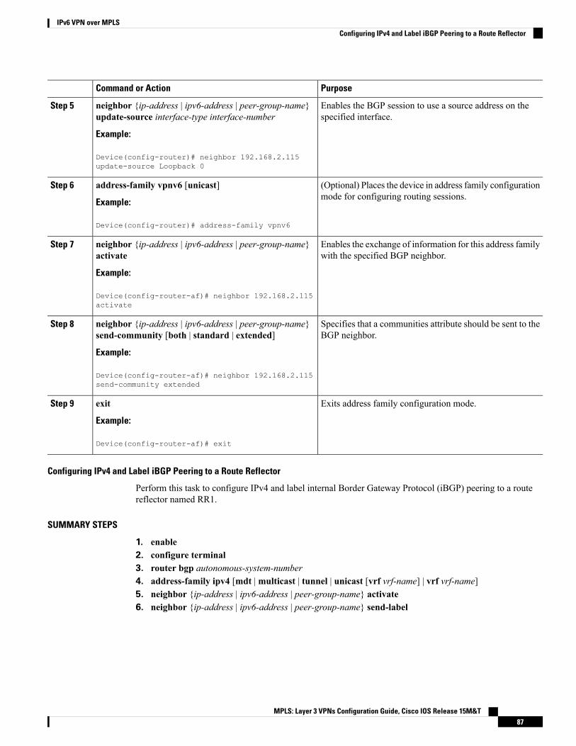
PurposeCommand or Action
Enables the BGP session to use a source address on thespecified interface.
neighbor {ip-address | ipv6-address | peer-group-name}update-source interface-type interface-number
Example:
Step 5
Device(config-router)# neighbor 192.168.2.115update-source Loopback 0
(Optional) Places the device in address family configurationmode for configuring routing sessions.
address-family vpnv6 [unicast]
Example:
Step 6
Device(config-router)# address-family vpnv6
Enables the exchange of information for this address familywith the specified BGP neighbor.
neighbor {ip-address | ipv6-address | peer-group-name}activate
Example:
Step 7
Device(config-router-af)# neighbor 192.168.2.115activate
Specifies that a communities attribute should be sent to theBGP neighbor.
neighbor {ip-address | ipv6-address | peer-group-name}send-community [both | standard | extended]
Example:
Step 8
Device(config-router-af)# neighbor 192.168.2.115send-community extended
Exits address family configuration mode.exit
Example:
Step 9
Device(config-router-af)# exit
Configuring IPv4 and Label iBGP Peering to a Route Reflector
Perform this task to configure IPv4 and label internal Border Gateway Protocol (iBGP) peering to a routereflector named RR1.
SUMMARY STEPS
1. enable2. configure terminal3. router bgp autonomous-system-number4. address-family ipv4 [mdt |multicast | tunnel | unicast [vrf vrf-name] | vrf vrf-name]5. neighbor {ip-address | ipv6-address | peer-group-name} activate6. neighbor {ip-address | ipv6-address | peer-group-name} send-label
MPLS: Layer 3 VPNs Configuration Guide, Cisco IOS Release 15M&T87
IPv6 VPN over MPLSConfiguring IPv4 and Label iBGP Peering to a Route Reflector

DETAILED STEPS
PurposeCommand or Action
Enables privileged EXEC mode.enableStep 1
Example: • Enter your password if prompted.
Device> enable
Enters global configuration mode.configure terminal
Example:
Step 2
Device# configure terminal
Configures the BGP routing process.router bgp autonomous-system-number
Example:
Step 3
Device(config)# router bgp 100
Enters address family configuration mode to configure arouting session using standard IPv4 address prefixes.
address-family ipv4 [mdt |multicast | tunnel | unicast[vrf vrf-name] | vrf vrf-name]
Example:
Step 4
Device(config-router)# address-family ipv4
Enables the exchange of information for this address familywith the specified BGP neighbor.
neighbor {ip-address | ipv6-address | peer-group-name}activate
Example:
Step 5
Device(config-router-af)# neighbor 192.168.2.115activate
Enables label exchange for this address family to thisneighbor in order to receive remote provider edge (PE) peer
neighbor {ip-address | ipv6-address | peer-group-name}send-label
Step 6
IPv4 loopback with label via RR1 in order to set up anend-to-end label switch path (LSP).Example:
Device(config-router-af)# neighbor 192.168.2.115send-label
Configuring the Route Reflector for a Multiautonomous-System Backbone
Configuring Peering to the PE VPN
SUMMARY STEPS
1. enable2. configure terminal3. router bgp autonomous-system-number4. neighbor {ip-address | ipv6-address | peer-group-name} remote-as as-number5. neighbor {ip-address | ipv6-address | peer-group-name} update-source interface-type interface-number
MPLS: Layer 3 VPNs Configuration Guide, Cisco IOS Release 15M&T88
IPv6 VPN over MPLSConfiguring the Route Reflector for a Multiautonomous-System Backbone

6. address-family vpnv6 [unicast]7. neighbor {ip-address | ipv6-address | peer-group-name} activate8. neighbor {ip-address | ipv6-address | peer-group-name} send-community [both | standard | extended]9. exit10. address-family ipv4 [mdt |multicast | tunnel | unicast [vrf vrf-name] | vrf vrf-name]11. neighbor {ip-address | ipv6-address | peer-group-name} activate12. neighbor {ip-address | ipv6-address | peer-group-name} send-label13. exit
DETAILED STEPS
PurposeCommand or Action
Enables privileged EXEC mode.enableStep 1
Example: • Enter your password if prompted.
Device> enable
Enters global configuration mode.configure terminal
Example:
Step 2
Device# configure terminal
Configures the Border Gateway Protocol (BGP) routingprocess.
router bgp autonomous-system-number
Example:
Step 3
Device(config)# router bgp 100
Adds an entry to the multiprotocol BGP neighbor table forpeering with the route reflector for InterAS.
neighbor {ip-address | ipv6-address | peer-group-name}remote-as as-number
Example:
Step 4
Device(config-router)# neighbor 192.168.2.115remote-as 100
Enables the BGP session to use a source address on thespecified interface.
neighbor {ip-address | ipv6-address | peer-group-name}update-source interface-type interface-number
Example:
Step 5
Device(config-router)# neighbor 192.168.2.115update-source Loopback 0
(Optional) Places the device in address familyconfiguration mode.
address-family vpnv6 [unicast]
Example:
Step 6
Device(config-router)# address-family vpnv6
MPLS: Layer 3 VPNs Configuration Guide, Cisco IOS Release 15M&T89
IPv6 VPN over MPLSConfiguring Peering to the PE VPN

PurposeCommand or Action
Enables the exchange of information for this address familywith the specified BGP neighbor.
neighbor {ip-address | ipv6-address | peer-group-name}activate
Example:
Step 7
Device(config-router-af)# neighbor 192.168.2.115activate
Specifies that a community attribute should be sent to theBGP neighbor.
neighbor {ip-address | ipv6-address | peer-group-name}send-community [both | standard | extended]
Example:
Step 8
Device(config-router-af)# neighbor 192.168.2.115send-community extended
Exits address family configuration mode.exit
Example:
Step 9
Device(config-router-af)# exit
Enters address family configuration mode to configure arouting session using standard IPv4 address prefixes.
address-family ipv4 [mdt |multicast | tunnel | unicast[vrf vrf-name] | vrf vrf-name]
Example:
Step 10
Device(config-router)# address-family ipv4
Enables the exchange of information for this address familywith the specified BGP neighbor.
neighbor {ip-address | ipv6-address | peer-group-name}activate
Example:
Step 11
Device(config-router-af)# neighbor 192.168.2.115activate
Enables label exchange for this address family to thisneighbor in order to send to the local provider edge (PE)
neighbor {ip-address | ipv6-address | peer-group-name}send-label
Step 12
the remote PE IPv4 loopback with a label in order to setup an end-to-end label switch path (LSP).Example:
Device(config-router-af)# neighbor 192.168.2.115send-label
Exits address family configuration mode.exit
Example:
Step 13
Device(config-router-af)# exit
MPLS: Layer 3 VPNs Configuration Guide, Cisco IOS Release 15M&T90
IPv6 VPN over MPLSConfiguring Peering to the PE VPN

Configuring the Route Reflector
SUMMARY STEPS
1. enable2. configure terminal3. router bgp autonomous-system-number4. neighbor {ip-address | ipv6-address | peer-group-name} remote-as as-number5. neighbor {ip-address | ipv6-address | peer-group-name} update-source interface-type interface-number6. address-family vpnv6 [unicast]7. neighbor {ip-address | ipv6-address | peer-group-name} activate8. neighbor {ip-address | ipv6-address | peer-group-name} send-community [both | standard | extended]9. neighbor {ip-address | ipv6-address | peer-group-name} route-reflector-client10. exit11. address-family ipv4 [mdt |multicast | tunnel | unicast [vrf vrf-name] | vrf vrf-name]12. neighbor {ip-address | ipv6-address | peer-group-name} activate13. neighbor {ip-address | ipv6-address | peer-group-name} send-label14. exit
DETAILED STEPS
PurposeCommand or Action
Enables privileged EXEC mode.enableStep 1
Example: • Enter your password if prompted.
Device> enable
Enters global configuration mode.configure terminal
Example:
Step 2
Device# configure terminal
Configures the Border Gateway Protocol (BGP) routingprocess.
router bgp autonomous-system-number
Example:
Step 3
Device(config)# router bgp 100
Adds an entry to the multiprotocol BGP neighbor table forpeering with the Virtual Private Network (VPN) provideredge (PE) for Interns.
neighbor {ip-address | ipv6-address | peer-group-name}remote-as as-number
Example:
Step 4
Device(config-router)# neighbor 192.168.2.127remote-as 100
Enables the BGP session to use a source address on thespecified interface.
neighbor {ip-address | ipv6-address | peer-group-name}update-source interface-type interface-number
Example:
Step 5
MPLS: Layer 3 VPNs Configuration Guide, Cisco IOS Release 15M&T91
IPv6 VPN over MPLSConfiguring the Route Reflector
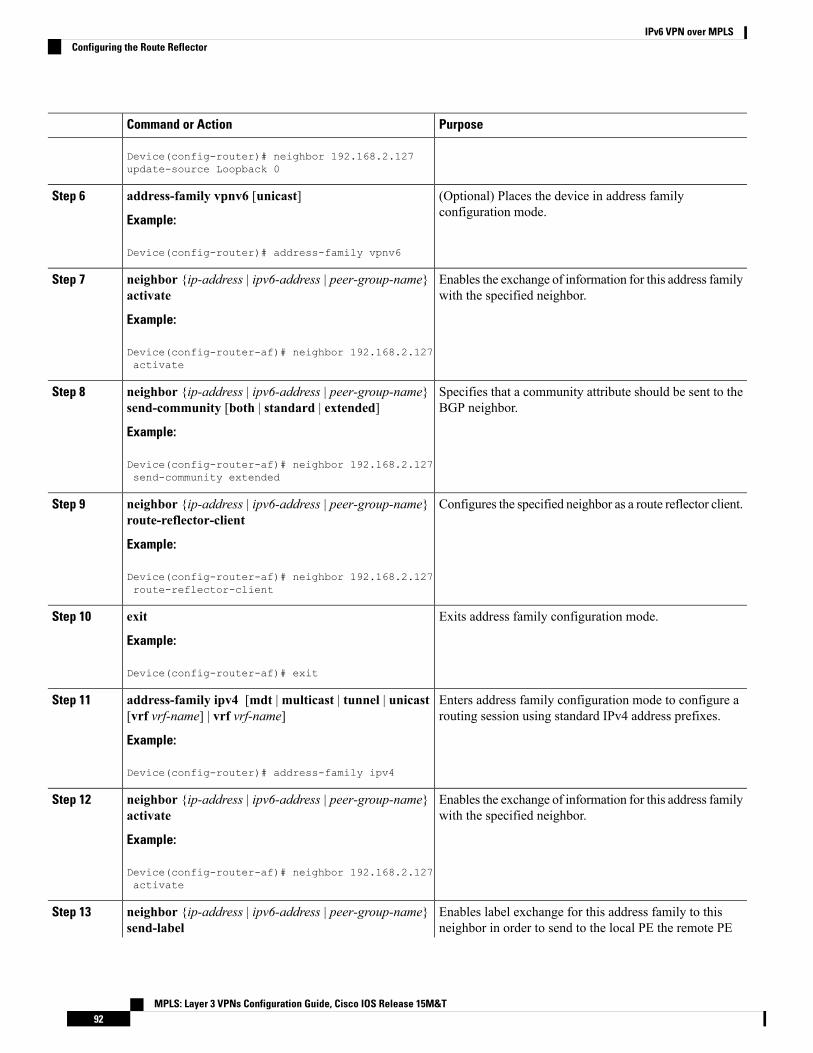
PurposeCommand or Action
Device(config-router)# neighbor 192.168.2.127update-source Loopback 0
(Optional) Places the device in address familyconfiguration mode.
address-family vpnv6 [unicast]
Example:
Step 6
Device(config-router)# address-family vpnv6
Enables the exchange of information for this address familywith the specified neighbor.
neighbor {ip-address | ipv6-address | peer-group-name}activate
Example:
Step 7
Device(config-router-af)# neighbor 192.168.2.127activate
Specifies that a community attribute should be sent to theBGP neighbor.
neighbor {ip-address | ipv6-address | peer-group-name}send-community [both | standard | extended]
Example:
Step 8
Device(config-router-af)# neighbor 192.168.2.127send-community extended
Configures the specified neighbor as a route reflector client.neighbor {ip-address | ipv6-address | peer-group-name}route-reflector-client
Step 9
Example:
Device(config-router-af)# neighbor 192.168.2.127route-reflector-client
Exits address family configuration mode.exit
Example:
Step 10
Device(config-router-af)# exit
Enters address family configuration mode to configure arouting session using standard IPv4 address prefixes.
address-family ipv4 [mdt |multicast | tunnel | unicast[vrf vrf-name] | vrf vrf-name]
Example:
Step 11
Device(config-router)# address-family ipv4
Enables the exchange of information for this address familywith the specified neighbor.
neighbor {ip-address | ipv6-address | peer-group-name}activate
Example:
Step 12
Device(config-router-af)# neighbor 192.168.2.127activate
Enables label exchange for this address family to thisneighbor in order to send to the local PE the remote PE
neighbor {ip-address | ipv6-address | peer-group-name}send-label
Step 13
MPLS: Layer 3 VPNs Configuration Guide, Cisco IOS Release 15M&T92
IPv6 VPN over MPLSConfiguring the Route Reflector

PurposeCommand or Action
IPv4 loopback with a label in order to set up an end-to-endLSP.
Example:
Device(config-router-af)# neighbor 192.168.2.127send-label
Exits address family configuration mode.exit
Example:
Step 14
Device(config-router-af)# exit
Configuring Peering to the Autonomous System Boundary Router
SUMMARY STEPS
1. enable2. configure terminal3. router bgp autonomous-system-number4. neighbor {ip-address | ipv6-address | peer-group-name} remote-as as-number5. neighbor {ip-address | ipv6-address | peer-group-name} update-source interface-type interface-number6. address-family ipv4 [mdt |multicast | tunnel | unicast [vrf vrf-name] | vrf vrf-name]7. neighbor {ip-address | ipv6-address | peer-group-name} activate8. neighbor {ip-address | ipv6-address | peer-group-name} send-label
DETAILED STEPS
PurposeCommand or Action
Enables privileged EXEC mode.enableStep 1
Example: • Enter your password if prompted.
Device> enable
Enters global configuration mode.configure terminal
Example:
Step 2
Device# configure terminal
Configures the Border Gateway Protocol (BGP) routingprocess.
router bgp autonomous-system-number
Example:
Step 3
Device(config)# router bgp 100
Adds an entry to the multiprotocol BGP neighbor table forpeering with the ASBR1.
neighbor {ip-address | ipv6-address | peer-group-name}remote-as as-number
Example:
Step 4
Device(config-router)# neighbor 192.168.2.102remote-as 100
MPLS: Layer 3 VPNs Configuration Guide, Cisco IOS Release 15M&T93
IPv6 VPN over MPLSConfiguring Peering to the Autonomous System Boundary Router

PurposeCommand or Action
Enables the BGP session to use a source address on thespecified interface.
neighbor {ip-address | ipv6-address | peer-group-name}update-source interface-type interface-number
Example:
Step 5
Device(config-router)# neighbor 192.168.2.102update-source Loopback 0
Enters address family configuration mode to configure arouting session using standard IPv4 address prefixes.
address-family ipv4 [mdt |multicast | tunnel | unicast[vrf vrf-name] | vrf vrf-name]
Example:
Step 6
Device(config-router)# address-family ipv4
Enables the exchange of information for this address familywith the specified BGP neighbor.
neighbor {ip-address | ipv6-address | peer-group-name}activate
Example:
Step 7
Device(config-router-af)# neighbor 192.168.2.102activate
Enables label exchange for this address family to thisneighbor in order to receive the remote PE IPv4 loopbackwith the label set to an end-to-end label switch path (LSP).
neighbor {ip-address | ipv6-address | peer-group-name}send-label
Example:
Step 8
Device(config-router-af)# neighbor 192.168.2.102send-label
Configuring Peering to Another ISP Route Reflector
Perform this task to configure peering to an Internet service provider (ISP) route reflector named RR2.
SUMMARY STEPS
1. enable2. configure terminal3. router bgp autonomous-system-number4. neighbor {ip-address | ipv6-address | peer-group-name} remote-as as-number5. neighbor {ip-address | ipv6-address | peer-group-name} update-source interface-type interface-number6. neighbor {ip-address | ipv6-address | peer-group-name} ebgp-multihop [ttl]7. address-family vpnv6 [unicast]8. neighbor {ip-address | ipv6-address | peer-group-name} activate9. neighbor {ip-address | ipv6-address | peer-group-name} send-community [both | standard | extended]10. neighbor {ip-address | ipv6-address | peer-group-name} next-hop-unchanged [allpaths]
MPLS: Layer 3 VPNs Configuration Guide, Cisco IOS Release 15M&T94
IPv6 VPN over MPLSConfiguring Peering to Another ISP Route Reflector
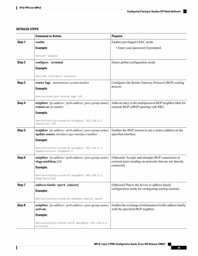
DETAILED STEPS
PurposeCommand or Action
Enables privileged EXEC mode.enableStep 1
Example: • Enter your password if prompted.
Device> enable
Enters global configuration mode.configure terminal
Example:
Step 2
Device# configure terminal
Configures the Border Gateway Protocol (BGP) routingprocess.
router bgp autonomous-system-number
Example:
Step 3
Device(config)# router bgp 100
Adds an entry to the multiprotocol BGP neighbor table forexternal BGP (eBGP) peering with RR2.
neighbor {ip-address | ipv6-address | peer-group-name}remote-as as-number
Example:
Step 4
Device(config-router)# neighbor 192.168.2.1remote-as 100
Enables the BGP session to use a source address on thespecified interface.
neighbor {ip-address | ipv6-address | peer-group-name}update-source interface-type interface-number
Example:
Step 5
Device(config-router)# neighbor 192.168.2.1update-source Loopback 0
(Optional) Accepts and attempts BGP connections toexternal peers residing on networks that are not directlyconnected.
neighbor {ip-address | ipv6-address | peer-group-name}ebgp-multihop [ttl]
Example:
Step 6
Device(config-router)# neighbor 192.168.2.1ebgp-multihop
(Optional) Places the device in address familyconfiguration mode for configuring routing sessions.
address-family vpnv6 [unicast]
Example:
Step 7
Device(config-router)# address-family vpnv6
Enables the exchange of information for this address familywith the specified BGP neighbor.
neighbor {ip-address | ipv6-address | peer-group-name}activate
Example:
Step 8
Device(config-router-af)# neighbor 192.168.2.1activate
MPLS: Layer 3 VPNs Configuration Guide, Cisco IOS Release 15M&T95
IPv6 VPN over MPLSConfiguring Peering to Another ISP Route Reflector

PurposeCommand or Action
Specifies that a communities attribute should be sent tothe BGP neighbor.
neighbor {ip-address | ipv6-address | peer-group-name}send-community [both | standard | extended]
Example:
Step 9
Device(config-router-af)# neighbor 192.168.2.1send-community extended
Enables an eBGP multihop peer to propagate to the nexthop unchanged for paths.
neighbor {ip-address | ipv6-address | peer-group-name}next-hop-unchanged [allpaths]
Example:
Step 10
Device(config-router-af)# neighbor 192.168.2.1next-hop-unchanged allpaths
Configuring the ASBR
Configuring Peering with Router Reflector RR1
SUMMARY STEPS
1. enable2. configure terminal3. router bgp autonomous-system-number4. neighbor {ip-address | ipv6-address | peer-group-name} remote-as as-number5. neighbor {ip-address | ipv6-address | peer-group-name} update-source interface-type interface-number6. address-family ipv4 [mdt |multicast | tunnel | unicast [vrf vrf-name] | vrf vrf-name7. neighbor {ip-address | ipv6-address | peer-group-name} activate8. neighbor {ip-address | ipv6-address | peer-group-name} send-label9. exit
DETAILED STEPS
PurposeCommand or Action
Enables privileged EXEC mode.enableStep 1
Example: • Enter your password if prompted.
Device> enable
Enters global configuration mode.configure terminal
Example:
Step 2
Device# configure terminal
Configures the Border Gateway Protocol (BGP) routingprocess.
router bgp autonomous-system-number
Example:
Step 3
MPLS: Layer 3 VPNs Configuration Guide, Cisco IOS Release 15M&T96
IPv6 VPN over MPLSConfiguring the ASBR

PurposeCommand or Action
Device(config)# router bgp 100
Adds an entry to the multiprotocol BGP neighbor table forpeering with RR1.
neighbor {ip-address | ipv6-address | peer-group-name}remote-as as-number
Example:
Step 4
Device(config-router)# neighbor 192.168.2.115remote-as 100
Enables the BGP session to use a source address on thespecified interface.
neighbor {ip-address | ipv6-address | peer-group-name}update-source interface-type interface-number
Example:
Step 5
Device(config-router)# neighbor 192.168.2.115update-source Loopback 0
Enters address family configuration mode to configure arouting session using standard IPv4 address prefixes.
address-family ipv4 [mdt |multicast | tunnel | unicast[vrf vrf-name] | vrf vrf-name
Example:
Step 6
Device(config-router)# address-family ipv4
Enables the exchange of information for this address familywith the specified BGP neighbor.
neighbor {ip-address | ipv6-address | peer-group-name}activate
Example:
Step 7
Device(config-router-af)# neighbor 192.168.2.115activate
Enables label exchange for this address family to thisneighbor in order to send to the local PE the remote PE IPv4
neighbor {ip-address | ipv6-address | peer-group-name}send-label
Step 8
loopback with a label in order to set up an end-to-end labelswitch path (LSP).Example:
Device(config-router-af)# neighbor 192.168.2.115send-label
Exits address family configuration mode.exit
Example:
Step 9
Device(config-router-af)# exit
Configuring Peering with the Other ISP ASBR2
SUMMARY STEPS
1. enable2. configure terminal3. router bgp autonomous-system-number
MPLS: Layer 3 VPNs Configuration Guide, Cisco IOS Release 15M&T97
IPv6 VPN over MPLSConfiguring Peering with the Other ISP ASBR2
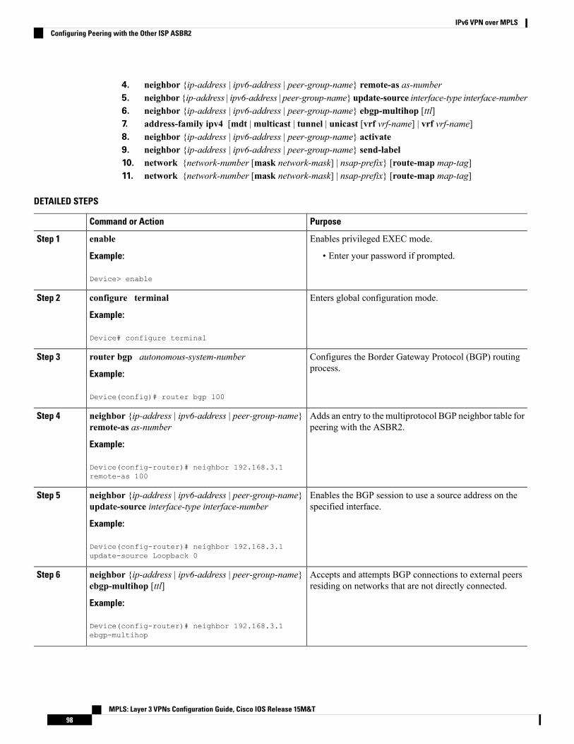
4. neighbor {ip-address | ipv6-address | peer-group-name} remote-as as-number5. neighbor {ip-address | ipv6-address | peer-group-name} update-source interface-type interface-number6. neighbor {ip-address | ipv6-address | peer-group-name} ebgp-multihop [ttl]7. address-family ipv4 [mdt |multicast | tunnel | unicast [vrf vrf-name] | vrf vrf-name]8. neighbor {ip-address | ipv6-address | peer-group-name} activate9. neighbor {ip-address | ipv6-address | peer-group-name} send-label10. network {network-number [mask network-mask] | nsap-prefix} [route-map map-tag]11. network {network-number [mask network-mask] | nsap-prefix} [route-map map-tag]
DETAILED STEPS
PurposeCommand or Action
Enables privileged EXEC mode.enableStep 1
Example: • Enter your password if prompted.
Device> enable
Enters global configuration mode.configure terminal
Example:
Step 2
Device# configure terminal
Configures the Border Gateway Protocol (BGP) routingprocess.
router bgp autonomous-system-number
Example:
Step 3
Device(config)# router bgp 100
Adds an entry to the multiprotocol BGP neighbor table forpeering with the ASBR2.
neighbor {ip-address | ipv6-address | peer-group-name}remote-as as-number
Example:
Step 4
Device(config-router)# neighbor 192.168.3.1remote-as 100
Enables the BGP session to use a source address on thespecified interface.
neighbor {ip-address | ipv6-address | peer-group-name}update-source interface-type interface-number
Example:
Step 5
Device(config-router)# neighbor 192.168.3.1update-source Loopback 0
Accepts and attempts BGP connections to external peersresiding on networks that are not directly connected.
neighbor {ip-address | ipv6-address | peer-group-name}ebgp-multihop [ttl]
Example:
Step 6
Device(config-router)# neighbor 192.168.3.1ebgp-multihop
MPLS: Layer 3 VPNs Configuration Guide, Cisco IOS Release 15M&T98
IPv6 VPN over MPLSConfiguring Peering with the Other ISP ASBR2

PurposeCommand or Action
Enters address family configuration mode to configure arouting session using standard IPv4 address prefixes.
address-family ipv4 [mdt |multicast | tunnel | unicast[vrf vrf-name] | vrf vrf-name]
Example:
Step 7
Device(config-router)# address-family ipv4
Enables the exchange of information for this address familywith the specified BGP neighbor.
neighbor {ip-address | ipv6-address | peer-group-name}activate
Example:
Step 8
Device(config-router-af)# neighbor 192.168.3.1activate
Enables label exchange for this address family to thisneighbor in order to receive the remote provider edge (PE)
neighbor {ip-address | ipv6-address | peer-group-name}send-label
Step 9
IPv4 loopback with a label in order to set up an end-to-endlabel switch path (LSP).Example:
Device(config-router-af)# neighbor 192.168.3.1send-label
Flags a network as local to this autonomous system andenters the network to the BGP table. This configuration isfor the PE VPN loopback.
network {network-number [mask network-mask] |nsap-prefix} [route-map map-tag]
Example:
Step 10
Device(config-router-af)# network 192.168.2.27mask 255.255.255.255
Flags a network as local to this autonomous system andenters the network to the BGP table. This configuration isfor the RR1 loopback.
network {network-number [mask network-mask] |nsap-prefix} [route-map map-tag]
Example:
Step 11
Device(config-router-af)# network 192.168.2.15mask 255.255.255.255
Configuring CSC for IPv6 VPNPerform this task to configure CsC-PE1 peering configuration with CsC-CE1.
SUMMARY STEPS
1. enable2. configure terminal3. hostname name4. router bgp autonomous-system-number5. address-family ipv6 [vrf vrf-name] [unicast |multicast]6. neighbor {ip-address | ipv6-address | peer-group-name} remote-as as-number7. neighbor {ip-address | ipv6-address | peer-group-name} activate
MPLS: Layer 3 VPNs Configuration Guide, Cisco IOS Release 15M&T99
IPv6 VPN over MPLSConfiguring CSC for IPv6 VPN
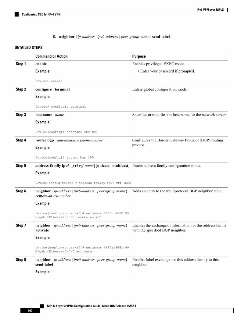
8. neighbor {ip-address | ipv6-address | peer-group-name} send-label
DETAILED STEPS
PurposeCommand or Action
Enables privileged EXEC mode.enableStep 1
Example: • Enter your password if prompted.
Device> enable
Enters global configuration mode.configure terminal
Example:
Step 2
Device# configure terminal
Specifies or modifies the host name for the network server.hostname name
Example:
Step 3
Device(config)# hostname CSC-PE1
Configures the Border Gateway Protocol (BGP) routingprocess.
router bgp autonomous-system-number
Example:
Step 4
Device(config)# router bgp 100
Enters address family configuration mode.address-family ipv6 [vrf vrf-name] [unicast |multicast]
Example:
Step 5
Device(config-router)# address-family ipv6 vrf ISP2
Adds an entry to the multiprotocol BGP neighbor table.neighbor {ip-address | ipv6-address | peer-group-name}remote-as as-number
Step 6
Example:
Device(config-router-af)# neighbor FE80::866C:99GigabitEthernet0/0/0 remote-as 200
Enables the exchange of information for this address familywith the specified BGP neighbor.
neighbor {ip-address | ipv6-address | peer-group-name}activate
Example:
Step 7
Device(config-router-af)# neighbor FE80::866C:99GigabitEthernet0/0/0 activate
Enables label exchange for this address family to thisneighbor.
neighbor {ip-address | ipv6-address | peer-group-name}send-label
Example:
Step 8
MPLS: Layer 3 VPNs Configuration Guide, Cisco IOS Release 15M&T100
IPv6 VPN over MPLSConfiguring CSC for IPv6 VPN

PurposeCommand or Action
Device(config-router-af)# neighbor FE80::866C:99GigabitEthernet0/0/0 send-label
Configuration Examples for IPv6 VPN over MPLS
Examples: IPv6 VPN over MPLS Routing
Example: BGP IPv6 Activity Summary
Device# show bgp ipv6 unicast summary
For address family: IPv6 UnicastBGP router identifier 192.168.2.126, local AS number 33751BGP table version is 15, main routing table version 1512 network entries using 1692 bytes of memory22 path entries using 1672 bytes of memory5/4 BGP path/bestpath attribute entries using 580 bytes of memory14 BGP rrinfo entries using 336 bytes of memory2 BGP AS-PATH entries using 48 bytes of memory0 BGP route-map cache entries using 0 bytes of memory0 BGP filter-list cache entries using 0 bytes of memoryBGP using 4328 total bytes of memoryDampening enabled. 0 history paths, 0 dampened pathsBGP activity 13/1 prefixes, 23/1 paths, scan interval 60 secsNeighbor V AS MsgRcvd MsgSent TblVer InQ OutQ Up/Down State/PfxRcd192.168.2.146 4 33751 991 983 15 0 0 16:26:21 10192.168.2.147 4 33751 991 983 15 0 0 16:26:22 10FE80::4F6B:44 GigabitEthernet1/0/0
4 20331 982 987 15 0 0 14:55:52 1
Example: Dumping the BGP IPv6 TablesEach table (for example, BGP IPv6, BGP IPv6 VPN) can be reviewed individually, as shown in the followingexample:
Device# show bgp ipv6 unicastBGP table version is 15, local router ID is 192.168.2.126Status codes: s suppressed, d damped, h history, * valid, > best, i - internal,
r RIB-failure, S StaleOrigin codes: i - IGP, e - EGP, ? - incomplete
Network Next Hop Metric LocPrf Weight Path* i2001:DB8:100::/48 ::FFFF:192.168.2.101 0 100 0 10000 ?*>i ::FFFF:192.168.2.101 0 100 0 10000 ?* i2001:DB8::1/128 ::FFFF:192.168.2.101 0 100 0 i*>i ::FFFF:192.168.2.101 0 100 0 i
Example: Dumping the IPv6 Routing TablesIPv6 routing tables identify each routing protocol contributor to routable entries, as shown in the followingexample:
MPLS: Layer 3 VPNs Configuration Guide, Cisco IOS Release 15M&T101
IPv6 VPN over MPLSConfiguration Examples for IPv6 VPN over MPLS

Device# show ipv6 routeIPv6 Routing Table - default - 13 entriesCodes: C - Connected, L - Local, S - Static, U - Per-user Static route
B - BGP, R - RIP, I1 - ISIS L1, I2 - ISIS L2IA - ISIS interarea, IS - ISIS summaryO - OSPF Intra, OI - OSPF Inter, OE1 - OSPF ext 1, OE2 - OSPF ext 2ON1 - OSPF NSSA ext 1, ON2 - OSPF NSSA ext 2
B 2001:DB8:100::/48 [200/0]via 192.168.2.101 Default-IP-Routing-Table, indirectly connected
B 2001:DB8::1/128 [200/0]via 192.168.2.101 Default-IP-Routing-Table, c
LC 2001:DB8::26/128 [0/0]via Loopback0, receive
From an IPv6 routing perspective, entries reachable over the MPLS backbone are listed as being indirectlyconnected, because MPLS is providing a Layer 2 tunnel mechanism.
Examples: IPv6 VPN over MPLS Forwarding
Example: PE-CE ConnectivityThe ipv6 ping and traceroute commands are useful to check connectivity from a provider edge (PE) to acustomer edge (CE), whether locally attached or remote over the Multiprotocol Label Switching (MPLS)backbone.
When a device is locally attached, one can use the ipv6 ping command with the CE link-local address (usedfor external BGP peering), as shown in the following example:
Device# ping FE80::4F6B:44%Loopback0Type escape sequence to abort.Sending 5, 100-byte ICMP Echos to FE80::4F6B:44, timeout is 2 seconds:!!!!!Success rate is 100 percent (5/5), round-trip min/avg/max = 28/33/48 ms
The ipv6 ping command also can be used to test remote PE or CE reachability, but only IPv6 global addressescan be used (link-local addresses are not advertised beyond the link):
Device# ping 2001:DB8:1120:1::44Type escape sequence to abort.Sending 5, 100-byte ICMP Echos to 2001:DB8:1120:1:44::1, timeout is 2 seconds:!!!!!Success rate is 100 percent (5/5), round-trip min/avg/max = 28/33/48 ms
Note that the ping ipv6 and traceroute command functions over MPLS require PEs and CEs to announceone IPv6 global prefix. Each 6PE device announces 2001:DB8::PE#/128, filtered at the autonomous systemedge. Each IPv6 CE configures 2001:DB8:prefix:CE#/128 and announces it as part as its less-specific prefix(2001:DB8:prefix::/n).
Reachability of remote PEs and CEs can be tested by using the traceroute command. If you have configuredall PEs with the no mpls ip propagate-ttl forwarded command, when the traceroute command is executedfrom a CE, its output will show only the IPv6 nodes:
Device# traceroute 2001:DB8::1Type escape sequence to abort.Tracing the route to 2001:DB8::11 2001:DB8::26 [AS 33751] 32 msec 32 msec 20 msec
MPLS: Layer 3 VPNs Configuration Guide, Cisco IOS Release 15M&T102
IPv6 VPN over MPLSExamples: IPv6 VPN over MPLS Forwarding

2 2001:DB8::1 [AS 33751] [MPLS: Label 73 Exp 0] 20 msec 20 msec 20 msec3 2001:DB8::1 [AS 33751] 28 msec 20 msec 20 msec
After the P devices have been upgraded with images that support ICMPv6, the traceroute command executedon the PE device (Time to Live [TTL] is then propagated) will also show P devices’ responses, as shown inthe following example:
Device# traceroute 2001:DB8::1
Type escape sequence to abort.Tracing the route to 2001:DB8::11 ::FFFF:172.20.25.1 [MPLS: Labels 38/73 Exp 0] 40 msec 32 msec 32 msec2 ::FFFF:172.20.10.1 [MPLS: Labels 30/73 Exp 0] 60 msec 32 msec 32 msec3 2001:DB8::1 [MPLS: Label 73 Exp 0] 32 msec 32 msec 16 msec
When run from a 6VPE device, both the ping ipv6 and traceroute commands accept a vrf argument, exactlyas in the case of VPNv4.
Note that the traceroute command is useful for evaluating the path across the MPLS backbone, but not fortroubleshooting data-plane failures. The P devices are IPv6 unaware (and are also VPNv4 unaware), so theICMPv6 messages that they generate in response to the traceroute command are forwarded to the egress PEusing the received label stack. The egress PE can route the ICMPv6 message to the source of the traceroute.When the MPLS path is broken, it is also broken from the ICMP message, which cannot reach the egress PE.
Examples: PE Imposition PathOn Cisco devices, the most useful tool for troubleshooting the imposition path for IPv6 is the show ipv6 cefcommand.
You can use the show ipv6 cef command to display the IPv6 forwarding table with label stacks used for eachdestination prefix, as shown in the following example:
Device# show ipv6 cef
2001:DB8:100::/48nexthop 172.20.25.1 GigabitEtherent0/0/0 label 38 72
2001:DB8::1/128nexthop 172.20.25.1 GigabitEtherent0/0/0 label 38 73
2001:DB8::26/128attached to Loopback0, receive
You can use the show ipv6 cef command to display details for a specific IPv6 entry in the forwarding tableand to analyze how the destination was resolved and the label stack computed, as shown in the followingexample:
Device# show ipv6 cef 2001:DB8:100::/48 internal
2001:DB8:100::/48, epoch 0, RIB[B], refcount 4sources: RIB
..recursive via 192.168.2.101[IPv4:Default] label 72, fib 0252B1F8, 1 terminal fibpath 024F56A8, path list 024F0BA8, share 0/1, type attached nexthopifnums: (none)path_list contains at least one resolved destination(s). HW IPv4 notified.nexthop 172.20.25.1 GigabitEtherent0/0/0 label 38, adjacency IP adj out of
GigabitEtherent0/0/0 0289BEF0output chain: label 72 label 38 TAG adj out of GigabitEtherent0/0/0 0289BD80
MPLS: Layer 3 VPNs Configuration Guide, Cisco IOS Release 15M&T103
IPv6 VPN over MPLSExamples: PE Imposition Path

The detailed output in the previous example shows that each label composing the label stack has a differentorigin that can be tracked down individually. The Border Gateway Protocol (BGP) table has the bottom label,as shown in the following example:
Device# show bgp ipv6 unicast 2001:DB8:100::/48
BGP routing table entry for 2001:DB8:100::/48, version 2Paths: (2 available, best #2, table default)Advertised to update-groups:
110000::FFFF:192.168.2.101 (metric 30) from 192.168.2.147 (192.168.2.147)Origin incomplete, metric 0, localpref 100, valid, internalOriginator: 192.168.2.101, Cluster list: 192.168.2.147,mpls labels in/out nolabel/72
10000::FFFF:192.168.2.101 (metric 30) from 192.168.2.146 (192.168.2.146)Origin incomplete, metric 0, localpref 100, valid, internal, bestOriginator: 192.168.2.101, Cluster list: 192.168.2.146,mpls labels in/out nolabel/72
Label Distribution Protocol (LDP), as shown in this example, displays the other labels:
Device# show mpls ldp bindings 192.168.2.101 32
lib entry: 192.168.2.101/32, rev 56local binding: label: 40remote binding: lsr: 192.168.2.119:0, label: 38
Device# show mpls ldp bindings 172.20.25.0 24lib entry: 172.20.25.0/24, rev 2
local binding: label: imp-nullremote binding: lsr: 192.168.2.119:0, label: imp-null
Examples: PE Disposition PathUse the following examples to troubleshoot the disposition path.
The following example shows the Multiprotocol Label Switching (MPLS) forwarding table information fortroubleshooting the disposition path.
Device# show mpls forwarding-table
Local Outgoing Prefix Bytes Label Outgoing Next HopLabel Label or VC or Tunnel Id Switched interface16 Pop Label 192.168.2.114/32 0 GE0/0/0 point2point17 26 192.168.2.146/32 0 GE0/0/0 point2point..72 No Label 2001:DB8:100::/48 63121 GE1/0/0 point2point73 Aggregate 2001:DB8::1/128 24123
The following example shows the label used for switching, which has been announced by iBGP (6PE in thisexample) and can be checked:
Device# show bgp ipv6 2001:DB8:100::/48
BGP routing table entry for 2001:DB8:100::/48, version 2Paths: (1 available, best #1, table default)Advertised to update-groups:
210000
MPLS: Layer 3 VPNs Configuration Guide, Cisco IOS Release 15M&T104
IPv6 VPN over MPLSExamples: PE Disposition Path

FE80::2710:2 (FE80::2710:2) from FE80::2710:2 GigabitEthernet1/0/0 (192.168.2.103)Origin incomplete, metric 0, localpref 100, valid, external, best,
Examples: Label Switch PathBecause the 6PE and 6VPE label switch path (LSP) endpoints are IPv4 addresses, the IPv4 tools fortroubleshooting LSPs are useful for detecting data-plane failures that would lead to IPv6 traffic black-holing.
The following example displays the LSP IPv4 end to analyze the LSP:
Device# show ipv6 route 2001:DB8::1/128
Routing entry for 2001:DB8::1/128Known via "bgp 33751", distance 200, metric 0, type internalRoute count is 1/1, share count 0Routing paths:192.168.2.101%Default-IP-Routing-Table indirectly connectedMPLS RequiredLast updated 02:42:12 ago
The following example shows the traceroute LSP:
Device# traceroute mpls ipv4 192.168.2.101/32 verbose
Tracing MPLS Label Switched Path to 192.168.2.101/32, timeout is 2 secondsCodes: '!' - success, 'Q' - request not transmitted,
'.' - timeout, 'U' - unreachable,'R' - downstream router but not target,'M' - malformed request
Type escape sequence to abort.0 172.20.25.2 0.0.0.0 MRU 1500 [Labels: 38 Exp: 0]
R 1 172.20.25.1 0.0.0.0 MRU 1500 [Labels: 30 Exp: 0] 40 ms, ret code 6R 2 172.20.10.1 0.0.0.0 MRU 1504 [Labels: implicit-null Exp: 0] 60 ms, ret code 6! 3 172.20.40.1 48 ms
Examples: IPv6 VPN over MPLS VRF
Examples: VRF InformationThe following entries show VRF information for 6VPE.
The following is sample output from a Cisco Express Forwarding FIB associated with a virtual routing andforwarding (VRF) instance named cisco1:
Device# show ipv6 cef vrf cisco1
2001:8::/64attached to GigabitEthernet0/0/12001:8::3/128receive2002:8::/64nexthop 10.1.1.2 GigabitEthernet0/1/0 label 22 192010::/64nexthop 2001:8::1 GigabitEthernet0/0/12012::/64attached to Loopback12012::1/128receive
MPLS: Layer 3 VPNs Configuration Guide, Cisco IOS Release 15M&T105
IPv6 VPN over MPLSExamples: Label Switch Path

The following is sample output regarding an IPv6 routing table associated with a VRF named cisco1:
Device# show ipv6 route vrf cisco1
IPv6 Routing Table cisco1 - 6 entriesCodes: C - Connected, L - Local, S - Static, R - RIP, B - BGP
U - Per-user Static routeI1 - ISIS L1, I2 - ISIS L2, IA - ISIS interareaO - OSPF intra, OI - OSPF inter, OE1 - OSPF ext 1, OE2 - OSPF ext 2
C 2001:8::/64 [0/0]via ::, GigabitEthernet0/0/1
L 2001:8::3/128 [0/0]via ::, GigabitEthernet0/0/1
B 2002:8::/64 [200/0]via ::FFFF:192.168.1.4,
B 2010::/64 [20/1]via 2001:8::1,
C 2012::/64 [0/0]via ::, Loopback1
L 2012::1/128 [0/0]via ::, Loopback1
Example: IPv6 VPN Configuration Using IPv4 Next HopThe following example illustrates a 6VPE next hop:
interface Loopback0ip address 192.168.2.11 255.255.255.255!router bgp 100neighbor 192.168.2.10 remote-as 100neighbor 192.168.2.10 update-source Loopback0!address-family vpnv6neighbor 192.168.2.10 activateneighbor 192.168.2.10 send-community extendedexit-address-family
By default, the next hop advertised will be the IPv6 Virtual Private Network (VPN) address:
[0:0]::FFFF:192.168.2.10
Note that it is a 192-bit address in the format of [RD]::FFFF:IPv4-address.
When the Border Gateway Protocol (BGP) IPv6 VPN peers share a common subnet, the MP_REACH_NLRIattribute contains a link-local address next hop in addition to the global address next hop. This situationtypically occurs in an interautonomous-system topology when autonomous system boundary routers (ASBRs)are facing each other. In that case, the link-local next hop is used locally, and the global next hop is readvertisedby BGP.
The BGP next hop is the keystone for building the label stack. The inner label is obtained from the BGPnetwork layer reachability information (NLRI), and the outer label is the Label Distribution Protocol (LDP)label to reach the IPv4 address embedded into the BGP next hop.
MPLS: Layer 3 VPNs Configuration Guide, Cisco IOS Release 15M&T106
IPv6 VPN over MPLSExample: IPv6 VPN Configuration Using IPv4 Next Hop

Additional ReferencesRelated Documents
Document TitleRelated Topic
Cisco Master Command List, AllReleases
Cisco IOS commands
IPv6 Configuration Guide LibraryIPv6 addressing and connectivity
Cisco IOS IPv6 CommandReference
IPv6 commands
IPv6 Feature MappingCisco IOS IPv6 features
"MPLS Virtual Private Networks"module in theMPLS Layer 3 VPNsConfiguration Guide
Configuring MPLS Layer 3 VPNs
Standards and RFCs
TitleStandard/RFC
IPv6RFCs
RFCs forIPv6
Technical Assistance
LinkDescription
http://www.cisco.com/cisco/web/support/index.htmlTheCisco Support andDocumentationwebsite providesonline resources to download documentation, software,and tools. Use these resources to install and configurethe software and to troubleshoot and resolve technicalissues with Cisco products and technologies. Access tomost tools on the Cisco Support and Documentationwebsite requires a Cisco.com user ID and password.
Glossary• 6VPE device—Provider edge device providing BGP-MPLS IPv6VPN service over an IPv4-basedMPLScore. It is a IPv6 VPN PE, dual-stack device that implements 6PE concepts on the core-facing interfaces.
• customer edge (CE) device—A service provider device that connects to VPN customer sites.
MPLS: Layer 3 VPNs Configuration Guide, Cisco IOS Release 15M&T107
IPv6 VPN over MPLSAdditional References

• Forwarding Information Base (FIB)—Table containing the information necessary to forward IPdatagrams. At a minimum, the FIB contains the interface identifier and next-hop information for eachreachable destination network prefix.
• inbound route filtering (IRF)—ABGP capability used for filtering incoming BGP updates that are notto be imported by the receiving PE device.
• IPv6 provider edge device (6PE device)—Device running a BGP-based mechanism to interconnectIPv6 islands over an MPLS-enabled IPv4 cloud.
• IPv6 VPN address—A IPv6 VPN address is a 24-byte identifier, beginning with an 8-byte routedistinguisher (RD) and ending with a 16-byte IPv6 address. Sometimes it is called an IPv6 VPN address.
• IPv6 VPN address family—The address-family identifier (AFI) identifies a particular network-layerprotocol and the subsequent AFI (SAFI) provides additional information. The AFI IPv6 SAFI VPN(AFI=2, SAFI=128) is called the IPv6 VPN address family. Sometimes it is called the IPv6 VPN addressfamily. Similarly AFI IPv4 SAFI VPN is the VPNv4 address family.
• network layer reachability information (NLRI)—BGP sends routing update messages containingNLRI to describe a route and how to get there. In this context, an NLRI is a prefix. A BGP update messagecarries one or more NLRI prefixes and the attributes of a route for the NLRI prefixes; the route attributesinclude a BGP next hop gateway address and community values.
• outbound route filtering (ORF)—A BGP capability used to filtering outgoing BGP routing updates.
• point of presence (POP)—Physical location where an interexchange carrier installed equipment tointerconnect with a local exchange carrier.
• provider edge (PE) device—A service provider device connected to VPN customer sites.
• route distinguisher (RD)—A 64-bit value prepended to an IPv6 prefix to create a globally unique IPv6VPN address.
• Routing Information Base (RIB)—Also called the routing table.
• Virtual routing and forwarding (VRF)—A VPN routing and forwarding instance in a PE.
• VRF table—A routing and a forwarding table associated to a VRF. This is a customer-specific tablethat enables the PE device to maintain independent routing states for each customer.
MPLS: Layer 3 VPNs Configuration Guide, Cisco IOS Release 15M&T108
IPv6 VPN over MPLSGlossary
C H A P T E R 6Configuring Route Maps to Control theDistribution of MPLS Labels Between Routers inan MPLS VPN
Route maps enable you to specify which routes are distributed with Multiprotocol Label Switching (MPLS)labels. Route maps also enable you to specify which routes with MPLS labels a router receives and adds toits Border Gateway Protocol (BGP) table.
• Finding Feature Information, on page 109• Restrictions for Using Route Maps with MPLS VPNs, on page 109• Prerequisites for Using Route Maps with MPLS VPNs, on page 110• Information About Route Maps in MPLS VPNs, on page 110• How to Configure Route Maps in an MPLS VPN, on page 110• Configuration Examples for Route Maps in MPLS VPNs, on page 116• Additional References, on page 118• Feature Information for Route Maps in MPLS VPNs, on page 120
Finding Feature InformationYour software release may not support all the features documented in this module. For the latest caveats andfeature information, see Bug Search Tool and the release notes for your platform and software release. Tofind information about the features documented in this module, and to see a list of the releases in which eachfeature is supported, see the feature information table.
Use Cisco Feature Navigator to find information about platform support and Cisco software image support.To access Cisco Feature Navigator, go to www.cisco.com/go/cfn. An account on Cisco.com is not required.
Restrictions for Using Route Maps with MPLS VPNsYou can use route maps with MPLS VPN Inter-AS with Autonomous System Boundary Routers (ASBRs)exchanging IPv4 routes withMPLS labels. You cannot use routemaps withMPLSVPN Inter-ASwith ASBRsexchanging VPN-IPv4 addresses.
MPLS: Layer 3 VPNs Configuration Guide, Cisco IOS Release 15M&T109

Prerequisites for Using Route Maps with MPLS VPNsBefore you configure and apply route maps, you need to create an access control list (ACL) and specify theroutes that the router should distribute with MPLS labels.
Information About Route Maps in MPLS VPNsWhen routers are configured to distribute routes with MPLS labels, all the routes are encoded with themultiprotocol extensions and contain MPLS labels. You can use a route map to control the distribution ofMPLS labels between routers.
Route maps enable you to specify which routes are distributed with MPLS labels. Route maps also enableyou to specify which routes with MPLS labels a router receives and adds to its BGP table. Route maps enableyou to specify the following:
• For a router distributing MPLS labels, you can specify which routes are distributed with an MPLS label.
• For a router receiving MPLS labels, you can specify which routes are accepted and installed in the BGPtable.
Route maps work with ACLs. You enter the routes into an ACL and then specify the ACLwhen you configurethe route map. You can configure a router to accept only routes that are specified in the route map. The routerchecks the routes listed in the BGP update message against the list of routes in the specified ACL. If a routein the BGP update message matches a route in the ACL, the route is accepted and added to the BGP table.
How to Configure Route Maps in an MPLS VPNPerform the following tasks to enable routers to sendMPLS labels with the routes specified in the route maps:
Configuring a Route Map for Incoming RoutesPerform this task to create a route map to filter arriving routes. You create an ACL and specify the routes thatthe router should accept and add to the BGP table.
SUMMARY STEPS
1. enable2. configure terminal3. router bgp as-number4. route-map map-name [permit | deny] sequence-number5. match ip address {access-list-number [access-list-number...| access-list-name...] access-list-name
[access-list-number...| access-list-name] | prefix-list prefix-list-name [prefix-list-name....]]6. match mpls-label7. exit
MPLS: Layer 3 VPNs Configuration Guide, Cisco IOS Release 15M&T110
Configuring Route Maps to Control the Distribution of MPLS Labels Between Routers in an MPLS VPNPrerequisites for Using Route Maps with MPLS VPNs
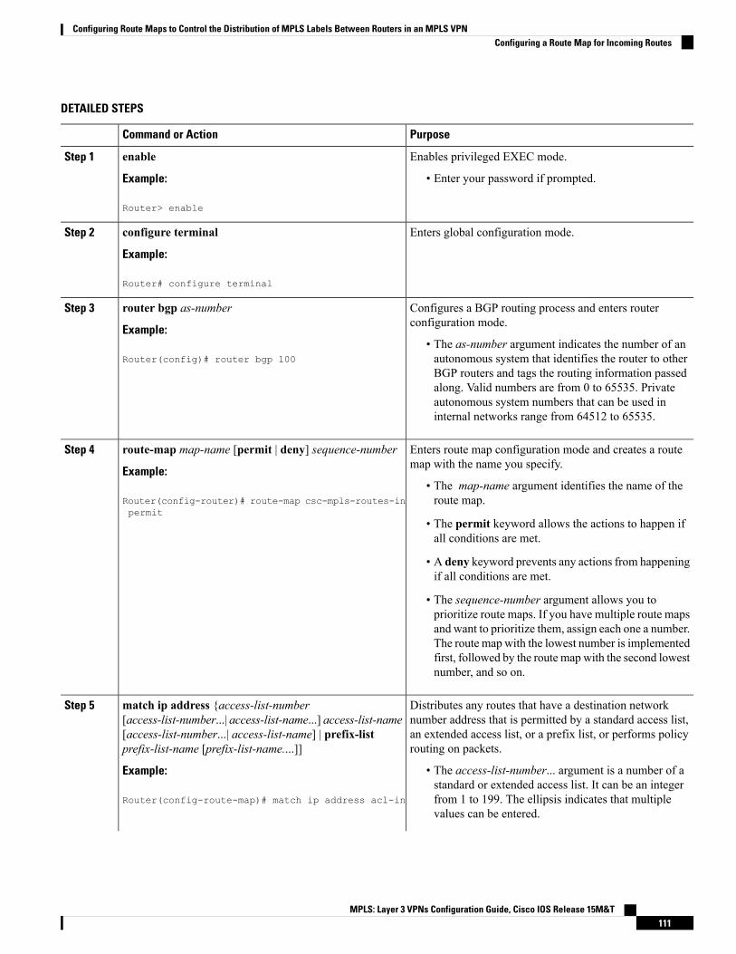
DETAILED STEPS
PurposeCommand or Action
Enables privileged EXEC mode.enableStep 1
Example: • Enter your password if prompted.
Router> enable
Enters global configuration mode.configure terminal
Example:
Step 2
Router# configure terminal
Configures a BGP routing process and enters routerconfiguration mode.
router bgp as-number
Example:
Step 3
• The as-number argument indicates the number of anautonomous system that identifies the router to otherRouter(config)# router bgp 100
BGP routers and tags the routing information passedalong. Valid numbers are from 0 to 65535. Privateautonomous system numbers that can be used ininternal networks range from 64512 to 65535.
Enters route map configuration mode and creates a routemap with the name you specify.
route-map map-name [permit | deny] sequence-number
Example:
Step 4
• The map-name argument identifies the name of theroute map.Router(config-router)# route-map csc-mpls-routes-in
permit• The permit keyword allows the actions to happen ifall conditions are met.
• A deny keyword prevents any actions from happeningif all conditions are met.
• The sequence-number argument allows you toprioritize route maps. If you have multiple route mapsand want to prioritize them, assign each one a number.The route map with the lowest number is implementedfirst, followed by the route map with the second lowestnumber, and so on.
Distributes any routes that have a destination networknumber address that is permitted by a standard access list,
match ip address {access-list-number[access-list-number...| access-list-name...] access-list-name
Step 5
an extended access list, or a prefix list, or performs policyrouting on packets.
[access-list-number...| access-list-name] | prefix-listprefix-list-name [prefix-list-name....]]
Example: • The access-list-number... argument is a number of astandard or extended access list. It can be an integer
Router(config-route-map)# match ip address acl-in from 1 to 199. The ellipsis indicates that multiplevalues can be entered.
MPLS: Layer 3 VPNs Configuration Guide, Cisco IOS Release 15M&T111
Configuring Route Maps to Control the Distribution of MPLS Labels Between Routers in an MPLS VPNConfiguring a Route Map for Incoming Routes
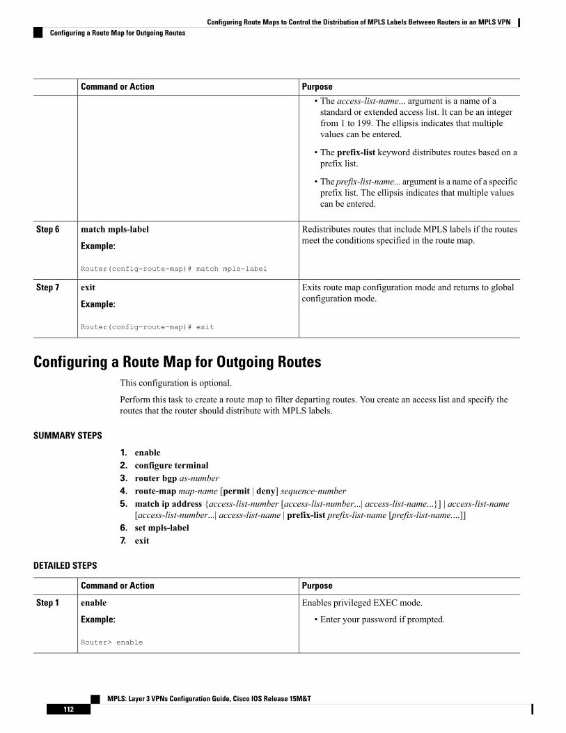
PurposeCommand or Action
• The access-list-name... argument is a name of astandard or extended access list. It can be an integerfrom 1 to 199. The ellipsis indicates that multiplevalues can be entered.
• The prefix-list keyword distributes routes based on aprefix list.
• The prefix-list-name... argument is a name of a specificprefix list. The ellipsis indicates that multiple valuescan be entered.
Redistributes routes that include MPLS labels if the routesmeet the conditions specified in the route map.
match mpls-label
Example:
Step 6
Router(config-route-map)# match mpls-label
Exits route map configuration mode and returns to globalconfiguration mode.
exit
Example:
Step 7
Router(config-route-map)# exit
Configuring a Route Map for Outgoing RoutesThis configuration is optional.
Perform this task to create a route map to filter departing routes. You create an access list and specify theroutes that the router should distribute with MPLS labels.
SUMMARY STEPS
1. enable2. configure terminal3. router bgp as-number4. route-map map-name [permit | deny] sequence-number5. match ip address {access-list-number [access-list-number...| access-list-name...}] | access-list-name
[access-list-number...| access-list-name | prefix-list prefix-list-name [prefix-list-name....]]6. set mpls-label7. exit
DETAILED STEPS
PurposeCommand or Action
Enables privileged EXEC mode.enableStep 1
Example: • Enter your password if prompted.
Router> enable
MPLS: Layer 3 VPNs Configuration Guide, Cisco IOS Release 15M&T112
Configuring Route Maps to Control the Distribution of MPLS Labels Between Routers in an MPLS VPNConfiguring a Route Map for Outgoing Routes
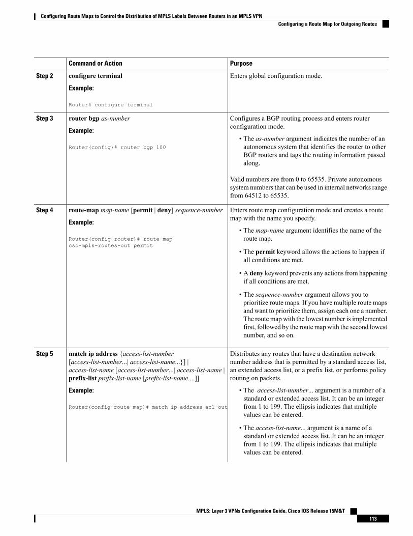
PurposeCommand or Action
Enters global configuration mode.configure terminal
Example:
Step 2
Router# configure terminal
Configures a BGP routing process and enters routerconfiguration mode.
router bgp as-number
Example:
Step 3
• The as-number argument indicates the number of anautonomous system that identifies the router to otherRouter(config)# router bgp 100
BGP routers and tags the routing information passedalong.
Valid numbers are from 0 to 65535. Private autonomoussystem numbers that can be used in internal networks rangefrom 64512 to 65535.
Enters route map configuration mode and creates a routemap with the name you specify.
route-map map-name [permit | deny] sequence-number
Example:
Step 4
• The map-name argument identifies the name of theroute map.Router(config-router)# route-map
csc-mpls-routes-out permit• The permit keyword allows the actions to happen ifall conditions are met.
• A deny keyword prevents any actions from happeningif all conditions are met.
• The sequence-number argument allows you toprioritize route maps. If you have multiple route mapsand want to prioritize them, assign each one a number.The route map with the lowest number is implementedfirst, followed by the route map with the second lowestnumber, and so on.
Distributes any routes that have a destination networknumber address that is permitted by a standard access list,
match ip address {access-list-number[access-list-number...| access-list-name...}] |
Step 5
an extended access list, or a prefix list, or performs policyrouting on packets.
access-list-name [access-list-number...| access-list-name |prefix-list prefix-list-name [prefix-list-name....]]
Example: • The access-list-number... argument is a number of astandard or extended access list. It can be an integer
Router(config-route-map)# match ip address acl-out from 1 to 199. The ellipsis indicates that multiplevalues can be entered.
• The access-list-name... argument is a name of astandard or extended access list. It can be an integerfrom 1 to 199. The ellipsis indicates that multiplevalues can be entered.
MPLS: Layer 3 VPNs Configuration Guide, Cisco IOS Release 15M&T113
Configuring Route Maps to Control the Distribution of MPLS Labels Between Routers in an MPLS VPNConfiguring a Route Map for Outgoing Routes

PurposeCommand or Action
• The prefix-list keyword distributes routes based ona prefix list.
• The prefix-list-name... argument is a name of a specificprefix list. The ellipsis indicates that multiple valuescan be entered.
Enables a route to be distributed with an MPLS label if theroute matches the conditions specified in the route map.
set mpls-label
Example:
Step 6
Router(config-route-map)# set mpls-label
Exits route map configuration mode and returns to globalconfiguration mode.
exit
Example:
Step 7
Router(config-route-map)# exit
Applying the Route Maps to the MPLS VPN Edge RoutersThis configuration is optional.
Perform this task to enable the edge routers to use the route maps.
SUMMARY STEPS
1. enable2. configure terminal3. router bgp as-number4. address-family ipv4 [multicast | unicast | vrf vrf-name]5. neighbor ip-address route-map map-name in6. neighbor ip-address route-map map-name out7. neighbor ip-address send-label8. exit-address-family9. end
DETAILED STEPS
PurposeCommand or Action
Enables privileged EXEC mode.enableStep 1
Example: • Enter your password if prompted.
Router> enable
Enters global configuration mode.configure terminal
Example:
Step 2
MPLS: Layer 3 VPNs Configuration Guide, Cisco IOS Release 15M&T114
Configuring Route Maps to Control the Distribution of MPLS Labels Between Routers in an MPLS VPNApplying the Route Maps to the MPLS VPN Edge Routers

PurposeCommand or Action
Router# configure terminal
Configures a BGP routing process and enters routerconfiguration mode.
router bgp as-number
Example:
Step 3
• The as-number argument indicates the number of anautonomous system that identifies the router to otherRouter(config)# router bgp 100
BGP routers and tags the routing information passedalong. Valid numbers are from 0 to 65535. Privateautonomous system numbers that can be used ininternal networks range from 64512 to 65535.
Specifies the IPv4 address family type and enters addressfamily configuration mode.
address-family ipv4 [multicast | unicast | vrf vrf-name]
Example:
Step 4
• Themulticast keyword specifies IPv4 multicastaddress prefixes.Router(config-router)# address-family ipv4 vrf vpn1
• The unicast keyword specifies IPv4 unicast addressprefixes.
• The vrf vrf-name keyword and argument specify thename of the VRF to associate with subsequent IPv4address family configuration mode commands.
Applies a route map to incoming routes.neighbor ip-address route-map map-name inStep 5
Example: • The ip-address argument specifies the router to whichthe route map is to be applied.
Router(config-router-af)# neighbor pp.0.0.1route-map csc-mpls-routes-in in • The map-name argument specifies the name of the
route map.
• The in keyword applies the route map to incomingroutes.
Applies a route map to outgoing routes.neighbor ip-address route-map map-name outStep 6
Example: • The ip-address argument specifies the router to whichthe route map is to be applied.
Router(config-router-af)# neighbor pp.0.0.1route-map csc-mpls-route-out out • The map-name argument specifies the name of the
route map.
• The out keyword applies the route map to outgoingroutes.
Enables a BGP router to sendMPLS labels with BGP routesto a neighboring BGP router.
neighbor ip-address send-label
Example:
Step 7
• The ip-address argument specifies the IP address ofthe neighboring router.Router(config-router-af)# neighbor pp.0.0.1
send-label
MPLS: Layer 3 VPNs Configuration Guide, Cisco IOS Release 15M&T115
Configuring Route Maps to Control the Distribution of MPLS Labels Between Routers in an MPLS VPNApplying the Route Maps to the MPLS VPN Edge Routers
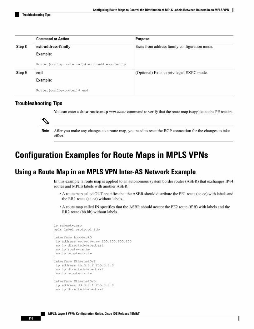
PurposeCommand or Action
Exits from address family configuration mode.exit-address-family
Example:
Step 8
Router(config-router-af)# exit-address-family
(Optional) Exits to privileged EXEC mode.end
Example:
Step 9
Router(config-router)# end
Troubleshooting TipsYou can enter a show route-mapmap-name command to verify that the route map is applied to the PE routers.
After you make any changes to a route map, you need to reset the BGP connection for the changes to takeeffect.
Note
Configuration Examples for Route Maps in MPLS VPNs
Using a Route Map in an MPLS VPN Inter-AS Network ExampleIn this example, a route map is applied to an autonomous system border router (ASBR) that exchanges IPv4routes and MPLS labels with another ASBR.
• A route map called OUT specifies that the ASBR should distribute the PE1 route (ee.ee) with labels andthe RR1 route (aa.aa) without labels.
• A route map called IN specifies that the ASBR should accept the PE2 route (ff.ff) with labels and theRR2 route (bb.bb) without labels.
ip subnet-zerompls label protocol tdp!interface Loopback0ip address ww.ww.ww.ww 255.255.255.255no ip directed-broadcastno ip route-cacheno ip mroute-cache!interface Ethernet0/2ip address hh.0.0.2 255.0.0.0no ip directed-broadcastno ip mroute-cache!interface Ethernet0/3ip address dd.0.0.1 255.0.0.0no ip directed-broadcast
MPLS: Layer 3 VPNs Configuration Guide, Cisco IOS Release 15M&T116
Configuring Route Maps to Control the Distribution of MPLS Labels Between Routers in an MPLS VPNTroubleshooting Tips

no ip mroute-cachempls label protocol ldptag-switching ip!router ospf 10log-adjacency-changesauto-cost reference-bandwidth 1000redistribute connected subnetspassive-interface Ethernet0/2network ww.ww.ww.ww 0.0.0.0 area 100network dd.0.0.0 0.255.255.255 area 100
router bgp 100bgp log-neighbor-changestimers bgp 10 30neighbor aa.aa.aa.aa remote-as 100neighbor aa.aa.aa.aa update-source Loopback0neighbor hh.0.0.1 remote-as 200no auto-summary!!address-family ipv4 ! Redistributing IGP into BGPredistribute ospf 10 ! so that PE1 & RR1 loopbacksneighbor aa.aa.aa.aa activate ! get into the BGP tableneighbor aa.aa.aa.aa send-labelneighbor hh.0.0.1 activateneighbor hh.0.0.1 advertisement-interval 5neighbor hh.0.0.1 send-labelneighbor hh.0.0.1 route-map IN in ! accepting routes in route map IN.neighbor hh.0.0.1 route-map OUT out ! distributing routes in route map OUT.neighbor kk.0.0.1 activateneighbor kk.0.0.1 advertisement-interval 5neighbor kk.0.0.1 send-labelneighbor kk.0.0.1 route-map IN in ! accepting routes in route map IN.neighbor kk.0.0.1 route-map OUT out ! distributing routes in route map OUT.no auto-summaryno synchronizationexit-address-family!ip default-gateway 3.3.0.1ip classless!access-list 1 permit ee.ee.ee.ee log !Setting up the access listsaccess-list 2 permit ff.ff.ff.ff logaccess-list 3 permit aa.aa.aa.aa logaccess-list 4 permit bb.bb.bb.bb logroute-map IN permit 10 !Setting up the route mapsmatch ip address 2match mpls-label!route-map IN permit 11match ip address 4!route-map OUT permit 12match ip address 3!route-map OUT permit 13match ip address 1set mpls-label!end
MPLS: Layer 3 VPNs Configuration Guide, Cisco IOS Release 15M&T117
Configuring Route Maps to Control the Distribution of MPLS Labels Between Routers in an MPLS VPNUsing a Route Map in an MPLS VPN Inter-AS Network Example

Using a Route Map in an MPLS VPN CSC Network ExampleThe following example creates two route maps, which are named:
• IN for incoming routes
• OUT for outgoing routes
The route maps specify the following:
• If an IP address in an incoming BGP update message matches an IP address in access list 99, the routeis added to the BGP table.
• If an IP address in an outbound BGP update message matches an IP address in access list 88, the routerdistributes that route.
The route maps are applied to the CSC-PE router with the address qq.0.0.1.
address-family ipv4 vrf vpn2neighbor qq.0.0.1 remote-as 200neighbor qq.0.0.1 activateneighbor qq.0.0.1 as-overrideneighbor qq.0.0.1 advertisement-interval 5neighbor qq.0.0.1 route-map IN inneighbor qq.0.0.1 route-map OUT outneighbor qq.0.0.1 send-label!access-list 88 permit rr.rr.rr.rraccess-list 88 permit ss.ss.ss.ssaccess-list 88 permit tt.tt.tt.ttaccess-list 99 permit uu.uu.uu.uuaccess-list 99 permit vv.vv.vv.vvaccess-list 99 permit ww.ww.ww.ww!route-map IN permit 1match ip address 99!route-map OUT permit 1match ip address 88set mpls-label!
Additional ReferencesRelated Documents
Document TitleRelated Topic
Configuring MPLS Layer 3 VPNsBasic MPLS VPNs
• MPLS VPN Carrier Supporting Carrier Using LDP and anIGP
• MPLS VPN Carrier Supporting Carrier with BGP
MPLS VPN Carrier Supporting Carrier
MPLS: Layer 3 VPNs Configuration Guide, Cisco IOS Release 15M&T118
Configuring Route Maps to Control the Distribution of MPLS Labels Between Routers in an MPLS VPNUsing a Route Map in an MPLS VPN CSC Network Example
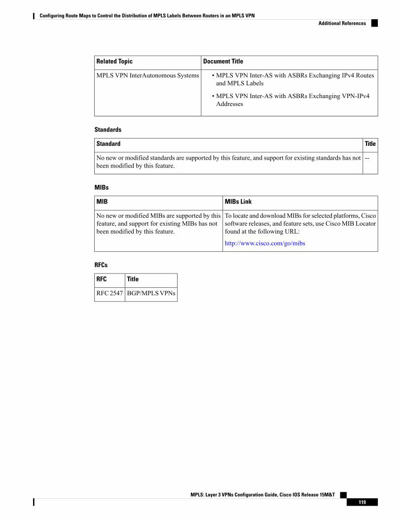
Document TitleRelated Topic
• MPLS VPN Inter-AS with ASBRs Exchanging IPv4 Routesand MPLS Labels
• MPLS VPN Inter-AS with ASBRs Exchanging VPN-IPv4Addresses
MPLS VPN InterAutonomous Systems
Standards
TitleStandard
--No new or modified standards are supported by this feature, and support for existing standards has notbeen modified by this feature.
MIBs
MIBs LinkMIB
To locate and downloadMIBs for selected platforms, Ciscosoftware releases, and feature sets, use CiscoMIB Locatorfound at the following URL:
http://www.cisco.com/go/mibs
No new or modified MIBs are supported by thisfeature, and support for existing MIBs has notbeen modified by this feature.
RFCs
TitleRFC
BGP/MPLSVPNsRFC2547
MPLS: Layer 3 VPNs Configuration Guide, Cisco IOS Release 15M&T119
Configuring Route Maps to Control the Distribution of MPLS Labels Between Routers in an MPLS VPNAdditional References

Technical Assistance
LinkDescription
http://www.cisco.com/techsupportThe Cisco Technical Support website contains thousands of pages ofsearchable technical content, including links to products, technologies,solutions, technical tips, and tools. Registered Cisco.com users can login from this page to access even more content.
The Cisco Technical Support website contains thousands of pages ofsearchable technical content, including links to products, technologies,solutions, technical tips, and tools. Registered Cisco.com users can login from this page to access even more content.
The Cisco Support website provides extensive online resources, includingdocumentation and tools for troubleshooting and resolving technical issueswith Cisco products and technologies.
To receive security and technical information about your products, youcan subscribe to various services, such as the Product Alert Tool (accessedfrom Field Notices), the Cisco Technical Services Newsletter, and ReallySimple Syndication (RSS) Feeds.
Access to most tools on the Cisco Support website requires a Cisco.comuser ID and password.
Feature Information for Route Maps in MPLS VPNsThe following table provides release information about the feature or features described in this module. Thistable lists only the software release that introduced support for a given feature in a given software releasetrain. Unless noted otherwise, subsequent releases of that software release train also support that feature.
Use Cisco Feature Navigator to find information about platform support and Cisco software image support.To access Cisco Feature Navigator, go to www.cisco.com/go/cfn. An account on Cisco.com is not required.
Table 5: Feature Information for Route Maps in MPLS VPNs
Feature Configuration InformationReleasesFeature Name
Route maps enable you to specify which routesare distributed with MPLS labels. Route mapsalso enable you to specify which routes withMPLS labels a router receives and adds to itsBGP table.
12.0(21)ST
12.0(22)S
12.0(23)S
12.2(13)T
12.0(24)S
12.2(14)S
12.0(27)S
12.0(29)S
This feature was included as part of thefollowing features:
• MPLS VPN Inter-Autonomous Systems- IPv4 BGP Label Distribution
• MPLS VPN Carrier Supporting Carrierwith IPv4 BGP Label Distribution
MPLS: Layer 3 VPNs Configuration Guide, Cisco IOS Release 15M&T120
Configuring Route Maps to Control the Distribution of MPLS Labels Between Routers in an MPLS VPNFeature Information for Route Maps in MPLS VPNs
C H A P T E R 7Assigning an ID Number to an MPLS VPN
You can identify Virtual Private Networks (VPNs) by a VPN identification number, as described in RFC2685. This implementation of the MPLS VPN ID feature is used for identifying a VPN.
• Finding Feature Information, on page 121• Restrictions for MPLS VPN ID, on page 121• Information About MPLS VPN ID, on page 122• How to Configure an MPLS VPN ID, on page 123• Configuration Examples for Assigning an ID Number to an MPLS VPN, on page 126• Additional References, on page 126• Feature Information for MPLS VPN ID, on page 127
Finding Feature InformationYour software release may not support all the features documented in this module. For the latest caveats andfeature information, see Bug Search Tool and the release notes for your platform and software release. Tofind information about the features documented in this module, and to see a list of the releases in which eachfeature is supported, see the feature information table.
Use Cisco Feature Navigator to find information about platform support and Cisco software image support.To access Cisco Feature Navigator, go to www.cisco.com/go/cfn. An account on Cisco.com is not required.
Restrictions for MPLS VPN IDThe MPLS VPN ID feature is not used to control the distribution of routing information or to associate IPaddresses with MPLS VPN ID numbers in the Multiprotocol Border Gateway Protocol (MP-BGP) VPNv4routing updates.
MPLS: Layer 3 VPNs Configuration Guide, Cisco IOS Release 15M&T121
Information About MPLS VPN ID
Introduction to MPLS VPN IDYou can identify Virtual Private Networks (VPNs) by a VPN identification number, as described in RFC2685. This implementation of the VPN ID feature is used for identifying a VPN. The VPN ID feature is notused to control the distribution of routing information or to associate IP addresses with VPN ID numbers inthe Multiprotocol Border Gateway Protocol (MP-BGP) VPNv4 routing updates.
Multiple VPNs can be configured in a device. A VPN is private and uses a private address space that mightalso be used by another VPN or by the Internet. The IP address used in a VPN is only significant to the VPNin which it exists. You can use a VPN name (a unique ASCII string) to reference a specific VPN configuredin the device. Alternately, you can use a VPN ID to identify a particular VPN in the device. The VPN IDfollows a standard specification (RFC 2685). To ensure that the VPN has a consistent VPN ID, assign thesame VPN ID to all the devices in the service provider network that services that VPN.
Configuration of a VPN ID for a VPN is optional. You can still use a VPN name to identify configured VPNsin the device. The VPN name is not affected by the VPN ID configuration. These are two independentmechanisms to identify VPNs.
Note
Components of the MPLS VPN IDEach MPLS VPN ID defined by RFC 2685 consists of the following elements:
• An Organizational Unique Identifier (OUI), a three-octet hex number: The IEEE Registration Authorityassigns OUIs to any company that manufactures components under the ISO/IEC 8802 standard. The OUIis used to generate universal LANMAC addresses and protocol identifiers for use in local andmetropolitanarea network applications. For example, an OUI for Cisco Systems is 00-03-6B (hex).
• A Virtual Private Network (VPN) index: a four-octet hex number, which identifies the VPN within thecompany.
Use the following vpn id command and specify the VPN ID:
vpn id oui:vpn-index
A colon separates the OUI from the VPN index.
Management Applications That Use MPLS VPN IDsYou can use several applications to manage Virtual Private Networks (VPNs) by MPLS VPN ID. Remoteaccess applications, such as the Remote Authentication Dial-In User Service (RADIUS) and Dynamic HostConfiguration Protocol (DHCP), can use the MPLS VPN ID feature to identify a VPN. RADIUS can use theMPLS VPN ID to assign dial-in users to the proper VPN, based on each user’s authentication information.
MPLS: Layer 3 VPNs Configuration Guide, Cisco IOS Release 15M&T122
Assigning an ID Number to an MPLS VPNInformation About MPLS VPN ID
Dynamic Host Configuration ProtocolUsing Dynamic Host Configuration Protocol (DHCP) network administrators can centrally manage andautomate the assignment of IP addresses in an organization’s network. The DHCP application uses the MPLSVPN ID as follows:
1. AVirtual Private Network (VPN) DHCP client requests a connection to a provider edge (PE) device froma virtual routing and forwarding (VRF) interface.
2. The PE device determines the VPN ID associated with that interface.
3. The PE device sends a request with the VPN ID and other information for assigning an IP address to theDHCP server.
4. The DHCP server uses the VPN ID and IP address information to process the request.
5. The DHCP server sends a response back to the PE device, allowing the VPN DHCP client access to theVPN.
Remote Authentication Dial-In User ServiceARADIUS server (or daemon) provides authentication and accounting services to one or more client networkaccess servers (NASs). RADIUS servers authenticate users and return all configuration information necessaryfor the client to deliver service to the users.
Typically, a user login consists of a query (Access-Request) from the NAS to the RADIUS server and acorresponding response (Access-Accept or Access-Reject) from the server.
• The Access-Request packet contains the username, encrypted password, NAS IP address, MPLS VPNID, and port. The format of the request also provides information on the type of session that the userwants to initiate.
• The RADIUS server returns an Access-Accept response if it finds the username and verifies the password.The response includes a list of attribute-value pairs that describe the parameters to be used for this session.If the user is not authenticated, an Access-Reject is sent by the RADIUS server and access is denied.
How to Configure an MPLS VPN ID
Specifying an MPLS VPN ID
Before you begin
Each virtual routing and forwarding (VRF) instance configured on a provider edge (PE) device can have anMPLS VPN ID configured. Configure all the PE devices that belong to the same Virtual Private Network(VPN) with the same VPN ID. Make sure the VPN ID is unique to the service provider network.
SUMMARY STEPS
1. enable2. configure terminal3. ip vrf vrf-name
MPLS: Layer 3 VPNs Configuration Guide, Cisco IOS Release 15M&T123
Assigning an ID Number to an MPLS VPNDynamic Host Configuration Protocol

4. vpn id oui:vpn-index :
DETAILED STEPS
PurposeCommand or Action
Enables privileged EXEC mode.enableStep 1
Example: • Enter your password if prompted.
Device> enable
Enters global configuration mode.configure terminal
Example:
Step 2
Device# configure terminal
Creates a VRF routing table and a Cisco ExpressForwarding forwarding table and enters VRF configurationmode.
ip vrf vrf-name
Example:
Device(config)# ip vrf vrf1
Step 3
• vrf-name—Name assigned to a VRF.
Assigns the VPN ID to the VRF.vpn id oui:vpn-index :Step 4
Example: • oui :—An organizationally unique identifier. The IEEEorganization assigns this identifier to companies. TheOUI is restricted to three octets.Device(config-vrf)# vpn id a1:3f6c
• vpn-index—This value identifies the VPN within thecompany. This VPN index is restricted to four octets.
Verifying the MPLS VPN ID Configuration
SUMMARY STEPS
1. enable2. show ip vrf3. show ip vrf id4. show ip vrf detail
DETAILED STEPS
Step 1 enable
Enables privileged EXEC mode.
Example:
Device> enableDevice#
MPLS: Layer 3 VPNs Configuration Guide, Cisco IOS Release 15M&T124
Assigning an ID Number to an MPLS VPNVerifying the MPLS VPN ID Configuration

Step 2 show ip vrf
Displays information about the virtual routing and forwarding (VRF) tables on the provider edge (PE) device. Thisexample displays three VRF tables called vpn1, vpn2, and vpn5.
Example:
Device# show ip vrf
Name Default RD Interfacesvpn1 100:1 FastEthernet1/1/1
FastEthernet1/0/0vpn2 <not set>vpn5 500:1 Loopback2
Step 3 show ip vrf id
Ensures that the PE device contains theMPLSVPN ID you specified. The following example shows that only VRF tablesvpn1 and vpn2 have VPN IDs assigned. The VRF table called vpn5 is not displayed, because it does not have a VPN ID.
Example:
Device# show ip vrf id
VPN Id Name RD2:3 vpn2 <not set>A1:3F6C vpn1 100:1
Step 4 show ip vrf detail
Displays all the VRFs on a PE device. This command displays all the MPLS VPN IDs that are configured on the device,their associated VRF names, and VRF route distinguishers (RDs). If a VRF table in the PE device has not been assignedan MPLS VPN ID, that VRF entry is not included in the output.
Example:
Device# show ip vrf detail
VRF vpn1; default RD 100:1; default VPNID A1:3F6CInterfaces:FastEthernet1/1/1 FastEthernet1/0/1
Connected addresses are not in global routing tableExport VPN route-target communitiesRT:100:1
Import VPN route-target communitiesRT:100:1 RT:500:1
No import route-mapNo export route-map
VRF vpn2; default RD <not set>; default VPNID 2:3No interfacesConnected addresses are not in global routing tableNo Export VPN route-target communitiesNo Import VPN route-target communitiesNo import route-mapNo export route-map
VRF vpn5; default RD 500:1; default VPNID <not set>Interfaces:
MPLS: Layer 3 VPNs Configuration Guide, Cisco IOS Release 15M&T125
Assigning an ID Number to an MPLS VPNVerifying the MPLS VPN ID Configuration

Configuration Examples for Assigning an ID Number to an MPLSVPN
Example: Specifying an MPLS VPN IDThe following example specifies the MPLS VPN ID assigned to the virtual routing and forwarding (VRF)table called vpn1:
Device# configure terminalDevice(config)# ip vrf vpn1Device(config-vrf)# vpn id a1:3f6c
Example: Verifying the MPLS VPN ID ConfigurationThe following is sample output of the show ip vrf detail command, one of the commands that can be usedto verify the MPLS VPN ID configuration. Use this command to see all the virtual routing and forwarding(VRF) instances on a provider edge (PE) device. This command displays all the MPLS VPN IDs that areconfigured on the device, their associated VRF names, and VRF route distinguishers (RDs). If a VRF tablein the PE device has not been assigned a VPN ID, that VRF entry is not included in the output.
Device# show ip vrf detail
VRF vpn1; default RD 100:1; default VPNID A1:3F6CInterfaces:FastEthernet1/1/1 FastEthernet1/0/1
Connected addresses are not in global routing tableExport VPN route-target communitiesRT:100:1
Import VPN route-target communitiesRT:100:1 RT:500:1
No import route-mapNo export route-map
VRF vpn2; default RD <not set>; default VPNID 2:3No interfacesConnected addresses are not in global routing tableNo Export VPN route-target communitiesNo Import VPN route-target communitiesNo import route-mapNo export route-map
VRF vpn5; default RD 500:1; default VPNID <not set>Interfaces:
Additional ReferencesRelated Documents
Document TitleRelated Topic
Cisco Master Command List, All ReleasesCisco IOS commands
MPLS: Layer 3 VPNs Configuration Guide, Cisco IOS Release 15M&T126
Assigning an ID Number to an MPLS VPNConfiguration Examples for Assigning an ID Number to an MPLS VPN
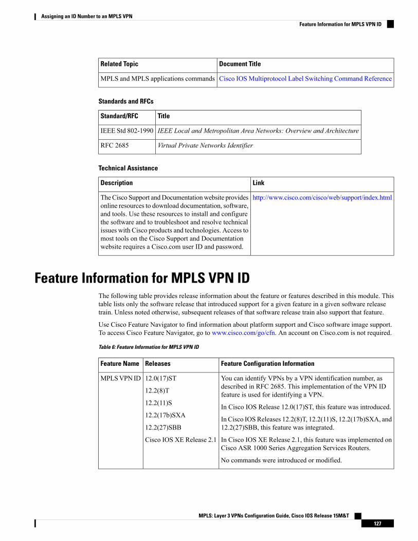
Document TitleRelated Topic
Cisco IOSMultiprotocol Label Switching Command ReferenceMPLS and MPLS applications commands
Standards and RFCs
TitleStandard/RFC
IEEE Local and Metropolitan Area Networks: Overview and ArchitectureIEEE Std 802-1990
Virtual Private Networks IdentifierRFC 2685
Technical Assistance
LinkDescription
http://www.cisco.com/cisco/web/support/index.htmlTheCisco Support andDocumentationwebsite providesonline resources to download documentation, software,and tools. Use these resources to install and configurethe software and to troubleshoot and resolve technicalissues with Cisco products and technologies. Access tomost tools on the Cisco Support and Documentationwebsite requires a Cisco.com user ID and password.
Feature Information for MPLS VPN IDThe following table provides release information about the feature or features described in this module. Thistable lists only the software release that introduced support for a given feature in a given software releasetrain. Unless noted otherwise, subsequent releases of that software release train also support that feature.
Use Cisco Feature Navigator to find information about platform support and Cisco software image support.To access Cisco Feature Navigator, go to www.cisco.com/go/cfn. An account on Cisco.com is not required.
Table 6: Feature Information for MPLS VPN ID
Feature Configuration InformationReleasesFeature Name
You can identify VPNs by a VPN identification number, asdescribed in RFC 2685. This implementation of the VPN IDfeature is used for identifying a VPN.
In Cisco IOS Release 12.0(17)ST, this feature was introduced.
In Cisco IOSReleases 12.2(8)T, 12.2(11)S, 12.2(17b)SXA, and12.2(27)SBB, this feature was integrated.
In Cisco IOS XE Release 2.1, this feature was implemented onCisco ASR 1000 Series Aggregation Services Routers.
No commands were introduced or modified.
12.0(17)ST
12.2(8)T
12.2(11)S
12.2(17b)SXA
12.2(27)SBB
Cisco IOS XE Release 2.1
MPLSVPN ID
MPLS: Layer 3 VPNs Configuration Guide, Cisco IOS Release 15M&T127
Assigning an ID Number to an MPLS VPNFeature Information for MPLS VPN ID

MPLS: Layer 3 VPNs Configuration Guide, Cisco IOS Release 15M&T128
Assigning an ID Number to an MPLS VPNFeature Information for MPLS VPN ID
C H A P T E R 8MPLS VPN Show Running VRF
The MPLS VPN Show Running VRF feature provides a Cisco IOS CLI option to display a subset of therunning configuration on a device that is linked to a Virtual Private Network (VPN) routing and forwarding(VRF) instance. You can display the configuration of a specific VRF or of all VRFs configured on a device.
On heavily loaded devices, the display of the configuration file might require several pages or screens. As theconfiguration increases in size and complexity, the possibility of misconfiguration also increases. You mightfind it difficult to trace a problem on a device where you have several VRFs configured. A command thatdisplays all the elements of the configuration linked to a VRF allows for easier troubleshooting on a per-VRFbasis and facilitates comparisons among configurations of different VRFs on the same device.
There are no configuration tasks for the MPLS VPN Show Running VRF feature.
• Finding Feature Information, on page 129• Prerequisites for MPLS VPN Show Running VRF, on page 129• Restrictions for MPLS VPN Show Running VRF, on page 130• Information About MPLS VPN Show Running VRF, on page 130• Additional References, on page 132• Feature Information for MPLS VPN Show Running VRF, on page 132• Glossary, on page 133
Finding Feature InformationYour software release may not support all the features documented in this module. For the latest caveats andfeature information, see Bug Search Tool and the release notes for your platform and software release. Tofind information about the features documented in this module, and to see a list of the releases in which eachfeature is supported, see the feature information table.
Use Cisco Feature Navigator to find information about platform support and Cisco software image support.To access Cisco Feature Navigator, go to www.cisco.com/go/cfn. An account on Cisco.com is not required.
Prerequisites for MPLS VPN Show Running VRF• A Cisco software image that supports virtual routing and forwarding (VRF) instances installed on thedevice
• At least one VRF configured on the device
MPLS: Layer 3 VPNs Configuration Guide, Cisco IOS Release 15M&T129

• Cisco Express Forwarding for Multiprotocol Label Switching (MPLS) Virtual Private Network (VPN)routing and forwarding
Restrictions for MPLS VPN Show Running VRFAny element of the running configuration of the device that is not linked directly to a virtual routing andforwarding (VRF) instance is not displayed. For example, a route map associated with a Border GatewayProtocol (BGP) neighbor in a VRF address-family configuration is not displayed. The VRF address-familyconfiguration under BGP is displayed, but the route-map configuration is not. An exception to this generalrule is the display of a controller configuration.
Information About MPLS VPN Show Running VRF
Configuration Elements Displayed for MPLS VPN Show Running VRFYou can display the running configuration associated with a specific virtual routing and forwarding (VRF)instance or all VRFs on the device by entering the show running-config vrf command. To display the runningconfiguration of a specific VRF, enter the name of the VRF as an argument to the show running-config vrfcommand. For example, for a VRF named vpn3, you enter:
Device# show running-config vrf vpn3
The show running-config vrf command displays the following elements of the running configuration on adevice:
• The VRF configuration (This includes any configuration that is applied in the VRF submode.)
• The configuration of each interface in the VRF
Entering a show run vrf vpn-name command is the same as executing a show running-config interface typenumber for each interface that you display by use of the show ip vrf vpn-name command. The interfacesdisplay in the same sorted order that you would expect from the show ip interface command.
For a channelized interface, the configuration of the controller is displayed (as shown by the show runcontroller controller-name command).
For a subinterface, the configuration of the main interface is displayed.
Display of VRF Routing Protocol ConfigurationOpen Shortest Path First (OSPF), Routing Information Protocol (RIP), Border Gateway Protocol (BGP),Enhanced Interior Gateway Routing Protocol (EIGRP), and static routing are routing protocols that supportthe virtual routing and forwarding (VRF) configuration.
OSPF has one process per VRF. The show running-config vrf command display includes the completeconfiguration of any OSPF process associated with the VRF. For example, the following shows the sampledisplay for OSPF process 101, which is associated with the VRF named vpn3:
router ospf 101 vrf vpn3
MPLS: Layer 3 VPNs Configuration Guide, Cisco IOS Release 15M&T130
MPLS VPN Show Running VRFRestrictions for MPLS VPN Show Running VRF

log-adjacency-changesarea 1 sham-link 10.43.43.43 10.23.23.23 cost 10network 172.17.0.0 0.255.255.255 area 1
RIP, BGP, and EIGRP support VRF address-family configuration. If a VRF address family for the VRF existsfor any of these routing protocols, a configuration in the following format is displayed:
routerprotocol{AS| PID}!address-family ipv4 vrfvrf-name...
Where the protocol argument is one of the following: rip, bgp or eigrp; the AS argument is an autonomoussystem number; the PID argument is a process identifier; and the vrf-name argument is the name of theassociated VRF.
The following shows a sample display for a BGPwith autonomous system number 100 associated with a VRFnamed vpn3:
!router bgp 100!address-family ipv4 vrf vpn3redistribute connectedredistribute ospf 101 match external 1 external 2no auto-summaryno synchronizationexit-address-family!
The show running-config vrf command also includes the configuration of any static routes configured inthe VRF. For example:
ip route vrf vpn1 10.1.1.0 255.255.255.0 10.30.1.1 globalip route vrf vpn1 10.1.2.0 255.255.255.0 10.125.1.2
Display of Configuration Not Directly Linked to a VRFAny element of a configuration that is not linked directly to a virtual routing and forwarding (VRF) instanceis not displayed. In some instances, the display of the configuration of an element that is not directly linkedto a VRF is required.
For example, the show running-config vrf command displays the configuration of an E1 controller whoseserial subinterfaces are in a VRF. The command displays the controller configuration and the subinterfaceconfiguration.
MPLS: Layer 3 VPNs Configuration Guide, Cisco IOS Release 15M&T131
MPLS VPN Show Running VRFDisplay of Configuration Not Directly Linked to a VRF

Additional ReferencesRelated Documents
Document TitleRelated Topic
Cisco Master Command List, All ReleasesCisco IOS commands
Cisco IOSMultiprotocol Label Switching Command ReferenceMPLS and MPLS applications commands
Technical Assistance
LinkDescription
http://www.cisco.com/cisco/web/support/index.htmlTheCisco Support andDocumentationwebsite providesonline resources to download documentation, software,and tools. Use these resources to install and configurethe software and to troubleshoot and resolve technicalissues with Cisco products and technologies. Access tomost tools on the Cisco Support and Documentationwebsite requires a Cisco.com user ID and password.
Feature Information for MPLS VPN Show Running VRFThe following table provides release information about the feature or features described in this module. Thistable lists only the software release that introduced support for a given feature in a given software releasetrain. Unless noted otherwise, subsequent releases of that software release train also support that feature.
Use Cisco Feature Navigator to find information about platform support and Cisco software image support.To access Cisco Feature Navigator, go to www.cisco.com/go/cfn. An account on Cisco.com is not required.
MPLS: Layer 3 VPNs Configuration Guide, Cisco IOS Release 15M&T132
MPLS VPN Show Running VRFAdditional References

Table 7: Feature Information for MPLS VPN Show Running VRF
Feature InformationReleasesFeature Name
The MPLS VPN Show Running VRF feature provides a CLI optionto display a subset of the running configuration on a device that islinked to a VRF. You can display the configuration of a specific VRFor of all VRFs configured on a device. A command that displays allthe elements of the configuration linked to a VRF allows for easiertroubleshooting on a per-VRF basis and facilitates comparisons amongconfigurations of different VRFs on the same device.
In 12.2(28)SB, this feature was introduced.
In 12.0(32)SY, support was added for a Cisco IOS 12.0SY release.
In 12.2(33)SRB, support was added for a Cisco IOS 12.2SR release.
In 122(33)SXH, support was added for a Cisco IOS 12.2SX release.
In 12.4(20)T, support was added for a Cisco IOS 12.4T release.
In Cisco IOS XE Release 2.5S, support was added for the Cisco ASR1000 Series Routers.
12.2(28)SB
12.0(32)SY
12.2(33)SRB
12.2(33)SXH
12.4(20)T
Cisco IOS XERelease 2.5
MPLS VPNShowRunningVRF
The following commands were introduced or modified: showpolicy-map interface brief, show running-config vrf.
GlossaryBGP—Border Gateway Protocol. An interdomain routing protocol that replaces External Gateway Protocol(EGP). BGP systems exchange reachability information with other BGP systems. BGP is defined by RFC1163.
EGP—External Gateway Protocol. An internet protocol for exchanging routing information betweenautonomous systems. EGP is documented in RFC 904. Not to be confused with the general term exteriorgateway protocol. EGP is an obsolete protocol that was replaced by Border Gateway Protocol (BGP).
EIGRP—Enhanced Interior Gateway Routing Protocol. Advanced version of Interior Gateway RoutingProtocol (IGRP) developed by Cisco. Provides superior convergence properties and operating efficiency, andcombines the advantages of link state protocols with those of distance vector protocols.
IGP—Interior Gateway Protocol. An internet protocol used to exchange routing information within anautonomous system. Examples of common Internet IGPs include Interior Gateway Routing Protocol (IGRP),Open Shortest Path First (OSPF), and Routing Information Protocol (RIP).
IGRP—Interior Gateway Routing Protocol. An Interior Gateway Protocol (IGP) developed by Cisco toaddress the issues associated with routing in large, heterogeneous networks.
MPLS—Multiprotocol Label Switching. A switching method that forwards IP traffic through the use of alabel. This label instructs the devices and the switches in the network where to forward each packet based onpreestablished IP routing information.
OSPF—Open Shortest Path First. A link-state, hierarchical, Interior Gateway Protocol (IGP) routing algorithmand routing protocol proposed as a successor to Routing Information Protocol (RIP) in the Internet community.
MPLS: Layer 3 VPNs Configuration Guide, Cisco IOS Release 15M&T133
MPLS VPN Show Running VRFGlossary

OSPF features include least-cost routing, multipath routing, and load balancing. OSPF was derived from anearly version of the Intermediate System-to-Intermediate System (IS-IS) protocol.
RIP—Routing Information Protocol. Internal Gateway Protocol (IGP) supplied with UNIXBerkeley SoftwareDistribution (BSD) systems. RIP is the most common IGP in the Internet. It uses hop count as a routing metric.
VPN—Virtual Private Network. The result of a device configuration that enables IP traffic to use tunnelingto travel securely over a public TCP/IP network.
MPLS: Layer 3 VPNs Configuration Guide, Cisco IOS Release 15M&T134
MPLS VPN Show Running VRFGlossary

C H A P T E R 9MPLS VPN Half-Duplex VRF
The MPLS VPN Half-Duplex VRF feature provides scalable hub-and-spoke connectivity for subscribers ofan Multiprotocol Label Switching (MPLS) Virtual Private Network (VPN) service. This feature addressesthe limitations of hub-and-spoke topologies by removing the requirement of one virtual routing and forwarding(VRF) instance per spoke. This feature also ensures that subscriber traffic always traverses the central linkbetween the wholesale service provider and the Internet service provider (ISP), whether the subscriber trafficis being routed to a remote network by way of the upstream ISP or to another locally or remotely connectedsubscriber.
• Finding Feature Information, on page 135• Prerequisites for MPLS VPN Half-Duplex VRF, on page 135• Restrictions for MPLS VPN Half-Duplex VRF, on page 136• Information About MPLS VPN Half-Duplex VRF, on page 136• How to Configure MPLS VPN Half-Duplex VRF, on page 138• Configuration Examples for MPLS VPN Half-Duplex VRF, on page 144• Additional References, on page 149• Feature Information for MPLS VPN Half-Duplex VRF, on page 150
Finding Feature InformationYour software release may not support all the features documented in this module. For the latest caveats andfeature information, see Bug Search Tool and the release notes for your platform and software release. Tofind information about the features documented in this module, and to see a list of the releases in which eachfeature is supported, see the feature information table.
Use Cisco Feature Navigator to find information about platform support and Cisco software image support.To access Cisco Feature Navigator, go to www.cisco.com/go/cfn. An account on Cisco.com is not required.
Prerequisites for MPLS VPN Half-Duplex VRFHalf-Duplex VRF is supported with either an MPLS core network or an IP core (VRF lite) network.
MPLS: Layer 3 VPNs Configuration Guide, Cisco IOS Release 15M&T135
Restrictions for MPLS VPN Half-Duplex VRFThe following features are not supported on interfaces configured with the MPLS VPN Half-Duplex VRFfeature:
• Multicast
• MPLS VPN Carrier Supporting Carrier
• MPLS VPN Interautonomous Systems
Information About MPLS VPN Half-Duplex VRF
MPLS VPN Half-Duplex VRF OverviewThe MPLS VPN Half-Duplex VRF feature provides:
• The MPLS VPN Half-Duplex VRF feature prevents local connectivity between subscribers at the spokeprovider edge (PE) device and ensures that a hub site provides subscriber connectivity. Any sites thatconnect to the same PE device must forward intersite traffic using the hub site. This ensures that therouting done at the spoke site moves from the access-side interface to the network-side interface or fromthe network-side interface to the access-side interface, but never from the access-side interface to theaccess-side interface.
• The MPLS VPN Half-Duplex VRF feature prevents situations where the PE device locally switches thespokes without passing the traffic through the upstream Internet service provider (ISP). This preventssubscribers from directly connecting to each other, which causes the wholesale service provider to loserevenue.
• The MPLS VPN Half-Duplex VRF feature improves scalability by removing the requirement of onevirtual routing and forwarding (VRF) instance per spoke. If the feature is not configured, when spokesare connected to the same PE device each spoke is configured in a separate VRF to ensure that the trafficbetween the spokes traverses the central link between the wholesale service provider and the ISP. However,this configuration is not scalable.When many spokes are connected to the same PE device, configurationof VRFs for each spoke becomes quite complex and greatly increases memory usage. This is especiallytrue in large-scale wholesale service provider environments that support high-density remote access toLayer 3 Virtual Private Networks (VPNs).
The figure below shows a sample hub-and-spoke topology.
MPLS: Layer 3 VPNs Configuration Guide, Cisco IOS Release 15M&T136
MPLS VPN Half-Duplex VRFRestrictions for MPLS VPN Half-Duplex VRF

Figure 10: Hub-and-Spoke Topology
Upstream and Downstream VRFsThe MPLS VPN Half-Duplex VRF feature uses two unidirectional virtual routing and forwarding (VRF)instances to forward IP traffic between the spokes and the hub PE device:
• The upstream VRF forwards IP traffic from the spokes toward the hub provider edge (PE) device. ThisVRF typically contains only a default route but might also contain summary routes and several defaultroutes. The default route points to the interface on the hub PE device that connects to the upstream Internetservice provider (ISP). The device dynamically learns about the default route from the routing updatesthat the hub PE device or home gateway sends.
Although the upstream VRF is typically populated from the hub, it is possible also to have a separate localupstream interface on the spoke PE for a different local service that would not be required to go through thehub: for example, a local Domain Name System (DNS) or game server service.
Note
• The downstreamVRF forwards traffic from the hub PE device back to the spokes. This VRF can contain:
• PPP peer routes for the spokes and per-user static routes received from the authentication,authorization, and accounting (AAA) server or from the Dynamic Host Control Protocol (DHCP)server
• Routes imported from the hub PE device
• Border Gateway Protocol (BGP), Open Shortest Path First (OSPF), Routing Information Protocol(RIP), or Enhanced Interior Gateway Routing Protocol (EIGRP) dynamic routes for the spokes
The spoke PE device redistributes routes from the downstream VRF into Multiprotocol Border GatewayProtocol (MP-BGP). That device typically advertises a summary route across theMultiprotocol Label Switching(MPLS) core for the connected spokes. The VRF configured on the hub PE device imports the advertisedsummary route.
A routing loop occurs when a per prefix label allocation mode is used, thereby not forwarding packets indownstream VRF. This can be prevented by using per VRF label allocation.
Reverse Path Forwarding CheckThe Reverse Path Forwarding (RPF) check ensures that an IP packet that enters a device uses the correctinbound interface. The MPLS VPN Half-Duplex VRF feature supports unicast RPF check on the spoke-side
MPLS: Layer 3 VPNs Configuration Guide, Cisco IOS Release 15M&T137
MPLS VPN Half-Duplex VRFUpstream and Downstream VRFs
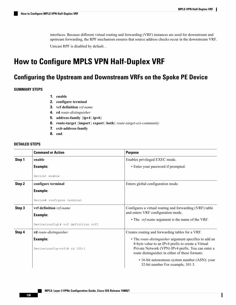
interfaces. Because different virtual routing and forwarding (VRF) instances are used for downstream andupstream forwarding, the RPF mechanism ensures that source address checks occur in the downstream VRF.
Unicast RPF is disabled by default. .
How to Configure MPLS VPN Half-Duplex VRF
Configuring the Upstream and Downstream VRFs on the Spoke PE Device
SUMMARY STEPS
1. enable2. configure terminal3. vrf definition vrf-name4. rd route-distinguisher5. address-family {ipv4 | ipv6}6. route-target {import | export | both} route-target-ext-community7. exit-address-family8. end
DETAILED STEPS
PurposeCommand or Action
Enables privileged EXEC mode.enableStep 1
Example: • Enter your password if prompted.
Device> enable
Enters global configuration mode.configure terminal
Example:
Step 2
Device# configure terminal
Configures a virtual routing and forwarding (VRF) tableand enters VRF configuration mode.
vrf definition vrf-name
Example:
Step 3
• The vrf-name argument is the name of the VRF.Device(config)# vrf definition vrf1
Creates routing and forwarding tables for a VRF.rd route-distinguisherStep 4
Example: • The route-distinguisher argument specifies to add an8-byte value to an IPv4 prefix to create a Virtual
Device(config-vrf)# rd 100:1 Private Network (VPN) IPv4 prefix. You can enter aroute distinguisher in either of these formats:
• 16-bit autonomous system number (ASN): your32-bit number For example, 101:3.
MPLS: Layer 3 VPNs Configuration Guide, Cisco IOS Release 15M&T138
MPLS VPN Half-Duplex VRFHow to Configure MPLS VPN Half-Duplex VRF
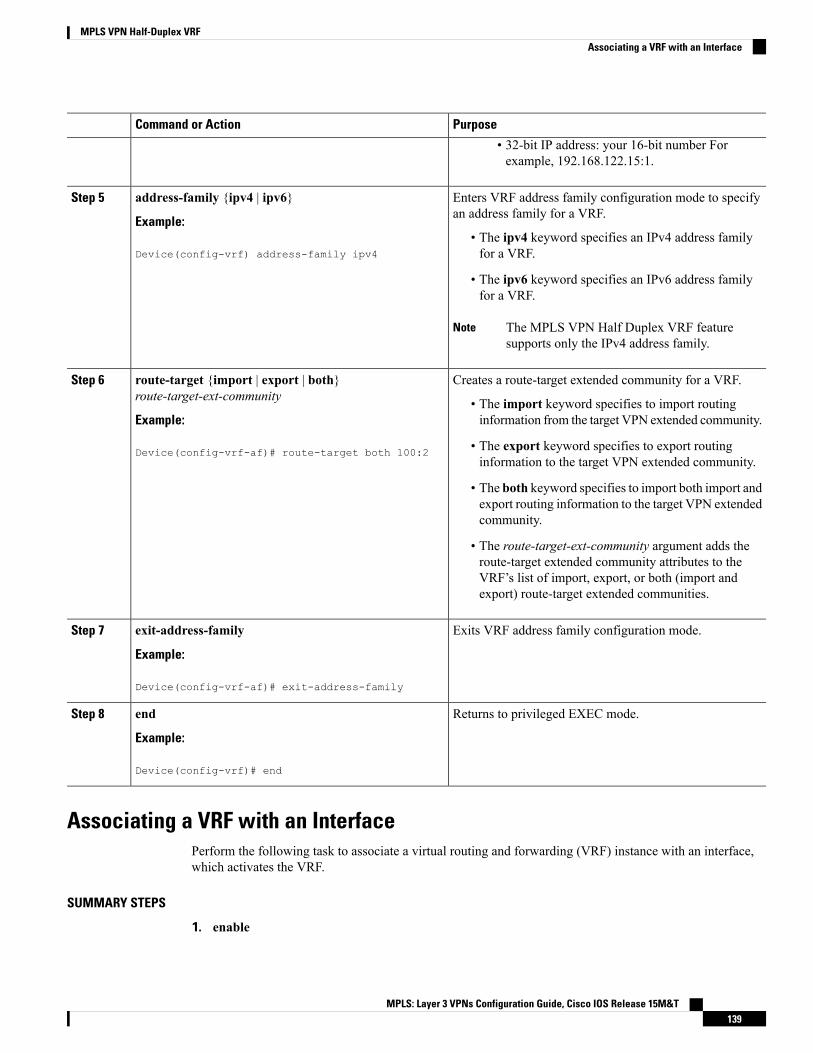
PurposeCommand or Action
• 32-bit IP address: your 16-bit number Forexample, 192.168.122.15:1.
Enters VRF address family configuration mode to specifyan address family for a VRF.
address-family {ipv4 | ipv6}
Example:
Step 5
• The ipv4 keyword specifies an IPv4 address familyfor a VRF.Device(config-vrf) address-family ipv4
• The ipv6 keyword specifies an IPv6 address familyfor a VRF.
The MPLS VPN Half Duplex VRF featuresupports only the IPv4 address family.
Note
Creates a route-target extended community for a VRF.route-target {import | export | both}route-target-ext-community
Step 6
• The import keyword specifies to import routinginformation from the target VPN extended community.Example:
Device(config-vrf-af)# route-target both 100:2 • The export keyword specifies to export routinginformation to the target VPN extended community.
• The both keyword specifies to import both import andexport routing information to the target VPN extendedcommunity.
• The route-target-ext-community argument adds theroute-target extended community attributes to theVRF’s list of import, export, or both (import andexport) route-target extended communities.
Exits VRF address family configuration mode.exit-address-family
Example:
Step 7
Device(config-vrf-af)# exit-address-family
Returns to privileged EXEC mode.end
Example:
Step 8
Device(config-vrf)# end
Associating a VRF with an InterfacePerform the following task to associate a virtual routing and forwarding (VRF) instance with an interface,which activates the VRF.
SUMMARY STEPS
1. enable
MPLS: Layer 3 VPNs Configuration Guide, Cisco IOS Release 15M&T139
MPLS VPN Half-Duplex VRFAssociating a VRF with an Interface

2. configure terminal3. interface type number4. vrf forwarding vrf-name [downstream vrf-name25. ip address ip-address mask [secondary]6. end
DETAILED STEPS
PurposeCommand or Action
Enables privileged EXEC mode.enableStep 1
Example: • Enter your password if prompted.
Device> enable
Enters global configuration mode.configure terminal
Example:
Step 2
Device# configure terminal
Configures an interface type and enters interfaceconfiguration mode.
interface type number
Example:
Step 3
• The type argument identifies the type of interface tobe configured.Device(config)# interface Ethernet 0/1
• The number argument identifies the port, connector,or interface card number.
Associates a VRF with an interface or subinterface.vrf forwarding vrf-name [downstream vrf-name2Step 4
Example: • The vrf-name argument is the name of the VRF.
Device(config-if)# vrf forwarding vrf1 • The downstream vrf-name2 keyword and argumentcombination is the name of the downstream VRF intowhich peer and per-user routes are installed.
Sets a primary or secondary IP address for an interface.ip address ip-address mask [secondary]Step 5
Example: • The ip-address argument is the IP address.
Device(config-if)# ip address 10.24.24.24255.255.255.255
• The mask argument is the mask of the associated IPsubnet.
• The secondary keyword specifies that the configuredaddress is a secondary IP address. If this keyword isomitted, the configured address is the primary IPaddress.
Returns to privileged EXEC mode.end
Example:
Step 6
MPLS: Layer 3 VPNs Configuration Guide, Cisco IOS Release 15M&T140
MPLS VPN Half-Duplex VRFAssociating a VRF with an Interface

PurposeCommand or Action
Device(config-if) end
Configuring the Downstream VRF for an AAA ServerTo configure the downstream VRF for an AAA (RADIUS) server in broadband or remote access situations,enter the following Cisco attribute value:
lcp:interface-config=ip vrf forwarding U downstream D
In standard VPN situations, enter instead the following Cisco attribute value:
ip:vrf-id=U downstream D
Verifying the MPLS VPN Half-Duplex VRF Configuration
SUMMARY STEPS
1. show vrf [ipv4 | ipv6] [brief | detail | id | interfaces | lock | select] [vrf-name]2. show ip route vrf vrf-name3. show running-config [interface type number]
DETAILED STEPS
Step 1 show vrf [ipv4 | ipv6] [brief | detail | id | interfaces | lock | select] [vrf-name]
Displays information about all of the virtual routing and forwarding (VRF) instances configured on the device, includingthe downstream VRF for each associated interface or virtual access interface (VAI):
Example:
Device# show vrfName Default RD InterfacesDown 100:1 POS3/0/3 [D]
POS3/0/1 [D]100:3 Loopback2
Virtual-Access3 [D]Virtual-Access4 [D]
Up 100:2 POS3/0/3POS3/0/1
100:4 Virtual-Access3
Use the show vrf detail vrf-name command to display detailed information about the VRF you specify, including allinterfaces, subinterfaces, and VAIs associated with the VRF.
If you do not specify a value for the vrf-name argument, detailed information about all of the VRFs configured on thedevice appears.
The following example shows how to display detailed information for the VRF called vrf1, in a broadband or remoteaccess case:
Example:
MPLS: Layer 3 VPNs Configuration Guide, Cisco IOS Release 15M&T141
MPLS VPN Half-Duplex VRFConfiguring the Downstream VRF for an AAA Server

Device# show vrf detail vrf1VRF D; default RD 2:0; default VPNID <not set>Interfaces:
Loopback2 Virtual-Access3 [D] Virtual-Access4 [D]Connected addresses are not in global routing tableExport VPN route-target communitiesRT:2:0
Import VPN route-target communitiesRT:2:1
No import route-mapNo export route-map
VRF U; default RD 2:1; default VPNID <not set>Interfaces:Virtual-Access3 Virtual-Access4
Connected addresses are not in global routing tableNo Export VPN route-target communitiesImport VPN route-target communitiesRT:2:1
No import route-mapNo export route-map
The following example shows the VRF detail in a standard Virtual Private Network (VPN) situation:
Example:
Device# show vrf detailVRF Down; default RD 100:1; default VPNID <not set> VRF Table ID = 1Description: import only from hub-peInterfaces:Pos3/0/3 [D] Pos3/0/1:0.1 [D]
Connected addresses are not in global routing tableExport VPN route-target communitiesRT:100:0
Import VPN route-target communitiesRT:100:1
No import route-mapNo export route-mapVRF label distribution protocol: not configuredVRF Up; default RD 100:2; default VPNID <not set> VRF Table ID = 2Interfaces:Pos3/0/1 Pos3/0/3
Connected addresses are not in global routing tableNo Export VPN route-target communitiesImport VPN route-target communitiesRT:100:1
No import route-mapNo export route-mapVRF label distribution protocol: not configured
Step 2 show ip route vrf vrf-name
Displays the IP routing table for the VRF you specify, and information about the per-user routes installed in the downstreamVRF.
The following example shows how to display the routing table for the downstream VRF named D, in a broadband orremote access situation:
Example:
Device# show ip route vrf D
Routing Table: D
MPLS: Layer 3 VPNs Configuration Guide, Cisco IOS Release 15M&T142
MPLS VPN Half-Duplex VRFVerifying the MPLS VPN Half-Duplex VRF Configuration

Codes: C - connected, S - static, R - RIP, M - mobile, B - BGPD - EIGRP, EX - EIGRP external, O - OSPF, IA - OSPF inter areaN1 - OSPF NSSA external type 1, N2 - OSPF NSSA external type 2E1 - OSPF external type 1, E2 - OSPF external type 2I - IS-IS, L1 - IS-IS level-1, L2 - IS-IS level-2, ia - IS-IS interarea* - candidate default, U - per-user static route, o - ODRP - periodic downloaded static route
Gateway of last resort is not set10.0.0.0/8 is variably subnetted, 5 subnets, 2 masksU 10.0.0.2/32 [1/0] via 10.0.0.1S 10.0.0.0/8 is directly connected, Null0U 10.0.0.5/32 [1/0] via 10.0.0.2C 10.8.1.2/32 is directly connected, Virtual-Access4C 10.8.1.1/32 is directly connected, Virtual-Access3
The following example shows how to display the routing table for the downstreamVRF named Down, in a standard VPNsituation:
Example:
Device# show ip route vrf Down
Routing Table: DownCodes: C - connected, S - static, R - RIP, M - mobile, B - BGP
D - EIGRP, EX - EIGRP external, O - OSPF, IA - OSPF inter areaN1 - OSPF NSSA external type 1, N2 - OSPF NSSA external type 2E1 - OSPF external type 1, E2 - OSPF external type 2I - IS-IS, su - IS-IS summary, L1 - IS-IS level-1, L2 - IS-IS level-2ia - IS-IS inter area, * - candidate default, U - per-user static routeo - ODR, P - periodic downloaded static route
Gateway of last resort is 10.13.13.13 to network 0.0.0.0C 10.2.0.0/8 is directly connected, Pos3/0/3
10.3.0.0/32 is subnetted, 1 subnetsB 10.4.16.16 [200/0] via 10.13.13.13, 1w3dB 10.6.0.0/8 [200/0] via 10.13.13.13, 1w3dC 10.0.0.0/8 is directly connected, Pos3/0/110.7.0.0/16 is subnetted, 1 subnetsB 10.7.0.0 [20/0] via 10.0.0.2, 1w3d
10.0.6.0/32 is subnetted, 1 subnetsB 10.0.6.14 [20/0] via 10.0.0.2, 1w3d
10.8.0.0/32 is subnetted, 1 subnetsB 10.8.15.15 [20/0] via 10.0.0.2, 1w3dB* 0.0.0.0/0 [200/0] via 10.0.0.13, 1w3d
The following example shows how to display the routing table for the upstream VRF named U in a broadband or remoteaccess situation:
Example:
Device# show ip route vrf URouting Table: UCodes: C - connected, S - static, R - RIP, M - mobile, B - BGP
D - EIGRP, EX - EIGRP external, O - OSPF, IA - OSPF inter areaN1 - OSPF NSSA external type 1, N2 - OSPF NSSA external type 2E1 - OSPF external type 1, E2 - OSPF external type 2I - IS-IS, L1 - IS-IS level-1, L2 - IS-IS level-2, ia - IS-IS interarea* - candidate default, U - per-user static route, o - ODRP - periodic downloaded static route
Gateway of last resort is 192.168.0.20 to network 0.0.0.010.0.0.0/32 is subnetted, 1 subnetsC 10.0.0.8 is directly connected, Loopback2B* 0.0.0.0/0 [200/0] via 192.168.0.20, 1w5d
MPLS: Layer 3 VPNs Configuration Guide, Cisco IOS Release 15M&T143
MPLS VPN Half-Duplex VRFVerifying the MPLS VPN Half-Duplex VRF Configuration

The following example shows how to display the routing table for the upstream VRF named Up in a standard VPNsituation:
Example:
Device# show ip route vrf UpRouting Table: UpCodes: C - connected, S - static, R - RIP, M - mobile, B - BGP
D - EIGRP, EX - EIGRP external, O - OSPF, IA - OSPF inter areaN1 - OSPF NSSA external type 1, N2 - OSPF NSSA external type 2E1 - OSPF external type 1, E2 - OSPF external type 2I - IS-IS, su - IS-IS summary, L1 - IS-IS level-1, L2 - IS-IS level-2ia - IS-IS inter area, * - candidate default, U - per-user static routeo - ODR, P - periodic downloaded static route
Gateway of last resort is 10.13.13.13 to network 0.0.0.010.2.0.0/32 is subnetted, 1 subnetsC 10.2.0.1 is directly connected, Pos3/0/3
10.3.0.0/32 is subnetted, 1 subnetsB 10.3.16.16 [200/0] via 10.13.13.13, 1w3dB 10.6.0.0/8 [200/0] via 10.13.13.13, 1w3d10.0.0.0/32 is subnetted, 1 subnetsC 10.0.0.1 is directly connected, Pos3/0/1B* 0.0.0.0/0 [200/0] via 10.13.13.13, 1w3d
Step 3 show running-config [interface type number]
Displays information about the interface you specify, including information about the associated upstream and downstreamVRFs.
The following example shows how to display information about subinterface POS 3/0/1:
Example:
Device# show running-config interface POS 3/0/1Building configuration...Current configuration : 4261 bytes!interface POS3/0/1ip vrf forwarding Up downstream Downip address 10.0.0.1 255.0.0.0end
Configuration Examples for MPLS VPN Half-Duplex VRF
Examples: Configuring the Upstream and Downstream VRFs on the Spoke PEDevice
The following example configures an upstream virtual routing and forwarding (VRF) instance named Up:
Device> enableDevice# configure terminalDevice(config)# vrf definition UpDevice(config-vrf)# rd 1:0Device(config-vrf)# address-family ipv4
MPLS: Layer 3 VPNs Configuration Guide, Cisco IOS Release 15M&T144
MPLS VPN Half-Duplex VRFConfiguration Examples for MPLS VPN Half-Duplex VRF

Device(config-vrf-af)# route-target import 1:0Device(config-vrf-af)# exit-address-family
The following example configures a downstream VRF named Down:
Device> enableDevice# configure terminalDevice(config)# vrf definition DownDevice(config-vrf)# rd 1:8Device(config-vrf)# address-family ipv4Device(config-vrf-af)# route-target import 1:8Device(config-vrf-af)# exit-address-family
Example: Associating a VRF with an InterfaceThe following example associates the virtual routing and forwarding (VRF) instance named Up with POS3/0/1 subinterface and specifies the downstream VRF named Down:
Device> enableDevice# configure terminalDevice(config)# interface POS 3/0/1Device(config-if)# vrf forwarding Up downstream DownDevice(config-if)# ip address 10.0.0.1 255.0.0.0
Example Configuring MPLS VPN Half-Duplex VRF Using Static CE-PE RoutingThis example uses the hub-and-spoke topology shown in the figure below with local authentication (that is,the RADIUS server is not used):Figure 11: Sample Topology
vrf definition Drd 1:8address-family ipv4route-target export 1:100exit-address-family!vrf definition Urd 1:0address-family ipv4route-target import 1:0exit-address-family
MPLS: Layer 3 VPNs Configuration Guide, Cisco IOS Release 15M&T145
MPLS VPN Half-Duplex VRFExample: Associating a VRF with an Interface
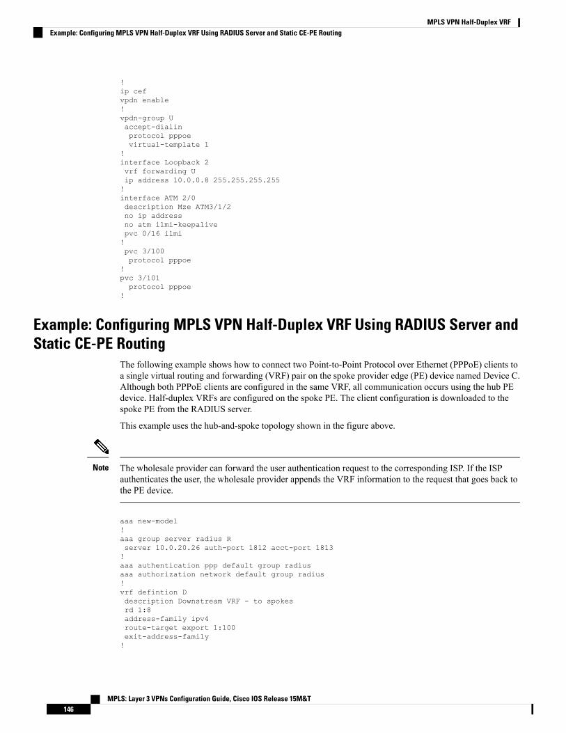
!ip cefvpdn enable!vpdn-group Uaccept-dialinprotocol pppoevirtual-template 1
!interface Loopback 2vrf forwarding Uip address 10.0.0.8 255.255.255.255!interface ATM 2/0description Mze ATM3/1/2no ip addressno atm ilmi-keepalivepvc 0/16 ilmi!pvc 3/100protocol pppoe
!pvc 3/101protocol pppoe
!
Example: Configuring MPLS VPN Half-Duplex VRF Using RADIUS Server andStatic CE-PE Routing
The following example shows how to connect two Point-to-Point Protocol over Ethernet (PPPoE) clients toa single virtual routing and forwarding (VRF) pair on the spoke provider edge (PE) device named Device C.Although both PPPoE clients are configured in the same VRF, all communication occurs using the hub PEdevice. Half-duplex VRFs are configured on the spoke PE. The client configuration is downloaded to thespoke PE from the RADIUS server.
This example uses the hub-and-spoke topology shown in the figure above.
The wholesale provider can forward the user authentication request to the corresponding ISP. If the ISPauthenticates the user, the wholesale provider appends the VRF information to the request that goes back tothe PE device.
Note
aaa new-model!aaa group server radius Rserver 10.0.20.26 auth-port 1812 acct-port 1813!aaa authentication ppp default group radiusaaa authorization network default group radius!vrf defintion Ddescription Downstream VRF - to spokesrd 1:8address-family ipv4route-target export 1:100exit-address-family!
MPLS: Layer 3 VPNs Configuration Guide, Cisco IOS Release 15M&T146
MPLS VPN Half-Duplex VRFExample: Configuring MPLS VPN Half-Duplex VRF Using RADIUS Server and Static CE-PE Routing

vrf definition Udescription Upstream VRF - to hubrd 1:0address-family ipv4route-target import 1:0exit-address-family!ip cefvpdn enable!vpdn-group Uaccept-dialinprotocol pppoevirtual-template 1
!interface Loopback2vrf forwarding Uip address 10.0.0.8 255.255.255.255!interface ATM2/0pvc 3/100protocol pppoe!pvc 3/101protocol pppoe!interface virtual-template 1no ip addressppp authentication chap!router bgp 1no synchronizationneighbor 172.16.0.34 remote-as 1neighbor 172.16.0.34 update-source Loopback0no auto-summary!address-family vpnv4neighbor 172.16.0.34 activateneighbor 172.16.0.34 send-community extendedauto-summaryexit-address-family!address-family ipv4 vrf Uno auto-summaryno synchronizationexit-address-family
!address-family ipv4 vrf Dredistribute staticno auto-summaryno synchronizationexit-address-family
!ip local pool U-pool 10.8.1.1 2.8.1.100ip route vrf D 10.0.0.0 255.0.0.0 Null0!radius-server host 10.0.20.26 auth-port 1812 acct-port 1813radius-server key cisco
MPLS: Layer 3 VPNs Configuration Guide, Cisco IOS Release 15M&T147
MPLS VPN Half-Duplex VRFExample: Configuring MPLS VPN Half-Duplex VRF Using RADIUS Server and Static CE-PE Routing

Example: Configuring MPLS VPN Half-Duplex VRF Using Dynamic CE-PERouting
The following example shows how to use Open Shortest Path First (OSPF) to dynamically advertise the routeson the spoke sites.
This example uses the hub-and-spoke topology shown in the figure above.
Creating the VRFs
vrf definition Downrd 100:1address-family ipv4route-target export 100:0exit-address-family!vrf definition Uprd 100:2address-family ipv4route-target import 100:1exit-address-family
Enabling MPLS
mpls ldp graceful-restartmpls ldp router-id Loopback0 forcempls label protocol ldp
Configuring BGP Toward Core
router bgp 100no bgp default ipv4-unicastbgp log-neighbor-changesbgp graceful-restart restart-time 120bgp graceful-restart stalepath-time 360bgp graceful-restartneighbor 10.13.13.13 remote-as 100neighbor 10.13.13.13 update-source Loopback0!address-family vpnv4neighbor 10.13.13.13 activateneighbor 10.13.13.13 send-community extendedbgp scan-time import 5exit-address-family
Configuring BGP Toward Edge
address-family ipv4 vrf Upno auto-summaryno synchronizationexit-address-family!address-family ipv4 vrf Downredistribute ospf 1000 vrf Downno auto-summary
MPLS: Layer 3 VPNs Configuration Guide, Cisco IOS Release 15M&T148
MPLS VPN Half-Duplex VRFExample: Configuring MPLS VPN Half-Duplex VRF Using Dynamic CE-PE Routing
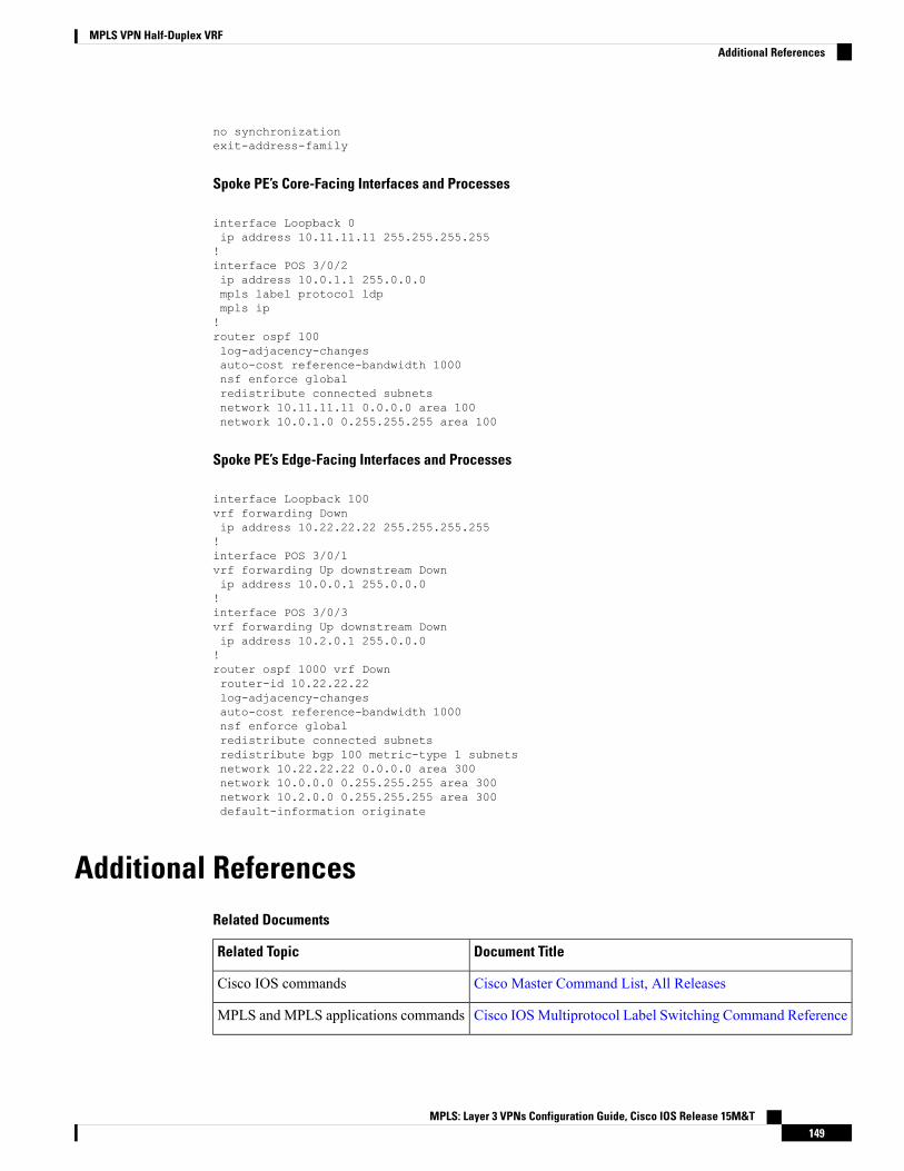
no synchronizationexit-address-family
Spoke PE’s Core-Facing Interfaces and Processes
interface Loopback 0ip address 10.11.11.11 255.255.255.255!interface POS 3/0/2ip address 10.0.1.1 255.0.0.0mpls label protocol ldpmpls ip!router ospf 100log-adjacency-changesauto-cost reference-bandwidth 1000nsf enforce globalredistribute connected subnetsnetwork 10.11.11.11 0.0.0.0 area 100network 10.0.1.0 0.255.255.255 area 100
Spoke PE’s Edge-Facing Interfaces and Processes
interface Loopback 100vrf forwarding Downip address 10.22.22.22 255.255.255.255!interface POS 3/0/1vrf forwarding Up downstream Downip address 10.0.0.1 255.0.0.0!interface POS 3/0/3vrf forwarding Up downstream Downip address 10.2.0.1 255.0.0.0!router ospf 1000 vrf Downrouter-id 10.22.22.22log-adjacency-changesauto-cost reference-bandwidth 1000nsf enforce globalredistribute connected subnetsredistribute bgp 100 metric-type 1 subnetsnetwork 10.22.22.22 0.0.0.0 area 300network 10.0.0.0 0.255.255.255 area 300network 10.2.0.0 0.255.255.255 area 300default-information originate
Additional ReferencesRelated Documents
Document TitleRelated Topic
Cisco Master Command List, All ReleasesCisco IOS commands
Cisco IOSMultiprotocol Label Switching Command ReferenceMPLS and MPLS applications commands
MPLS: Layer 3 VPNs Configuration Guide, Cisco IOS Release 15M&T149
MPLS VPN Half-Duplex VRFAdditional References

Document TitleRelated Topic
“MPLS Virtual Private Networks” moduleMPLS VPNs
“MPLS VPN VRF CLI for IPv4 and IPv6 VPNs” moduleConfiguring IPv4 and IPv6 VRFs
Standards and RFCs
TitleStandard/RFC
BGP/MPLSVPNsRFC 2547
Technical Assistance
LinkDescription
http://www.cisco.com/cisco/web/support/index.htmlTheCisco Support andDocumentationwebsite providesonline resources to download documentation, software,and tools. Use these resources to install and configurethe software and to troubleshoot and resolve technicalissues with Cisco products and technologies. Access tomost tools on the Cisco Support and Documentationwebsite requires a Cisco.com user ID and password.
Feature Information for MPLS VPN Half-Duplex VRFThe following table provides release information about the feature or features described in this module. Thistable lists only the software release that introduced support for a given feature in a given software releasetrain. Unless noted otherwise, subsequent releases of that software release train also support that feature.
Use Cisco Feature Navigator to find information about platform support and Cisco software image support.To access Cisco Feature Navigator, go to www.cisco.com/go/cfn. An account on Cisco.com is not required.
Table 8: Feature Information for MPLS VPN Half-Duplex VRF
Feature InformationReleasesFeature Name
This feature ensures that VPN clients that connect to thesame PE device at the edge of the MPLS VPN use the hubsite to communicate.
In Cisco IOS Release 12.3(6), this feature was introduced.
In Cisco IOS Release 12.4(20)T, this feature was integrated.
In Cisco IOS Release 12.2(28)SB, this feature was integrated
In Cisco IOS XE Release 2.5, this feature was implementedon the CiscoASR 1000 Series Aggregation Services Routers.
12.3(6)
12.3(11)T
12.2(28)SB
Cisco IOS XE Release2.5
MPLS VPN - HalfDuplex VRF(HDVRF) Supportwith Static Routing
MPLS: Layer 3 VPNs Configuration Guide, Cisco IOS Release 15M&T150
MPLS VPN Half-Duplex VRFFeature Information for MPLS VPN Half-Duplex VRF
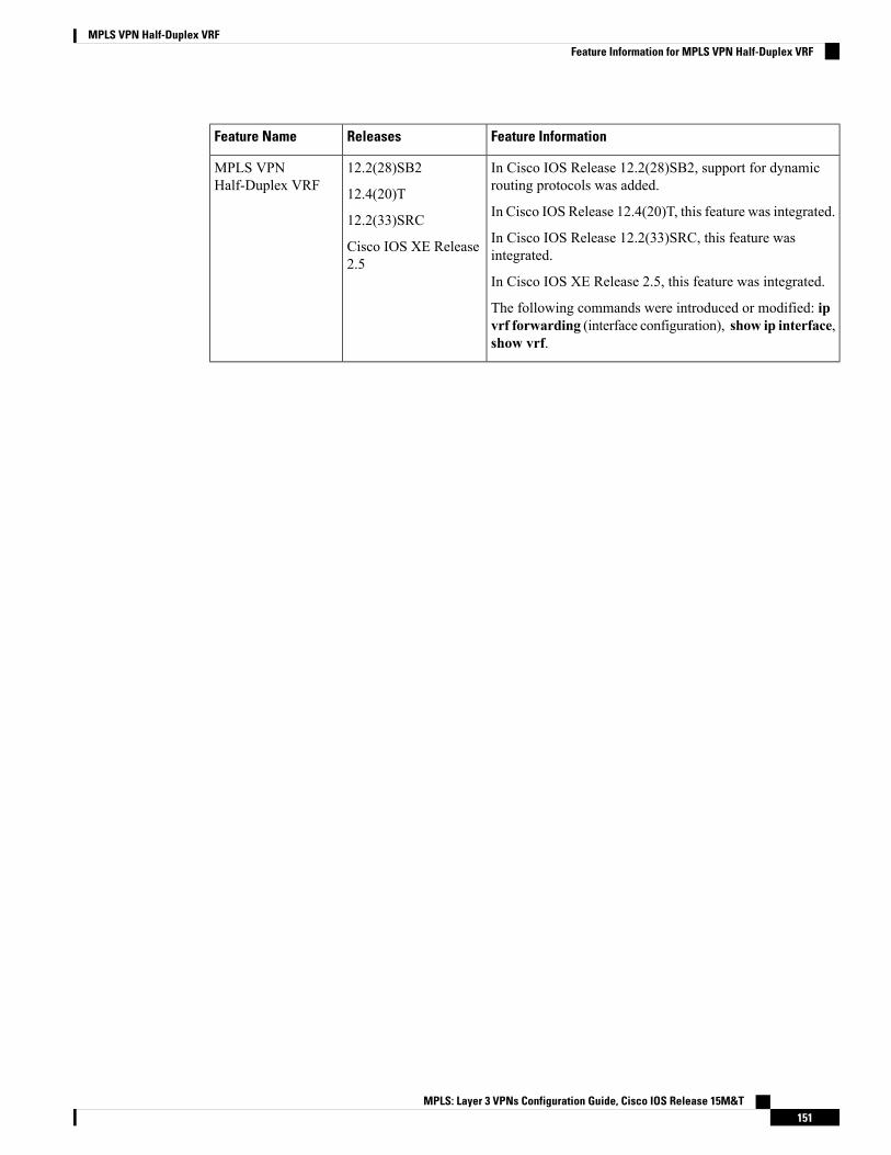
Feature InformationReleasesFeature Name
In Cisco IOS Release 12.2(28)SB2, support for dynamicrouting protocols was added.
In Cisco IOS Release 12.4(20)T, this feature was integrated.
In Cisco IOS Release 12.2(33)SRC, this feature wasintegrated.
In Cisco IOS XE Release 2.5, this feature was integrated.
The following commands were introduced or modified: ipvrf forwarding (interface configuration), show ip interface,show vrf.
12.2(28)SB2
12.4(20)T
12.2(33)SRC
Cisco IOS XE Release2.5
MPLS VPNHalf-Duplex VRF
MPLS: Layer 3 VPNs Configuration Guide, Cisco IOS Release 15M&T151
MPLS VPN Half-Duplex VRFFeature Information for MPLS VPN Half-Duplex VRF

MPLS: Layer 3 VPNs Configuration Guide, Cisco IOS Release 15M&T152
MPLS VPN Half-Duplex VRFFeature Information for MPLS VPN Half-Duplex VRF
C H A P T E R 10MPLS VPN VRF CLI for IPv4 and IPv6 VPNs
The MPLS VPN VRF CLI for IPv4 and IPv6 VPNs feature introduces Cisco commands that allow you toenable an IPv4 and IPv6 VPN in the same VRF instance and to simplify the migration from a single-protocolVRF configuration to a multiprotocol VRF configuration. A multiprotocol VRF allows you to share routetargets policies (import and export) between IPv4 and IPv6 or to configure separate route-target policies forIPv4 and IPv6 VPNs.
This document describes how to configure a Virtual Private Network (VPN) routing and forwarding (VRF)instance for IPv4 and IPv6 VPNs and describes how to upgrade your existing single-protocol IPv4-only VRFto a multiprotocol VRF configuration.
• Finding Feature Information, on page 153• Prerequisites for MPLS VPN VRF CLI for IPv4 and IPv6 VPNs, on page 153• Restrictions for MPLS VPN VRF CLI for IPv4 and IPv6 VPNs, on page 154• Information About MPLS VPN VRF CLI for IPv4 and IPv6 VPNs, on page 154• How to Configure MPLS VPN VRF CLI for IPv4 and IPv6 VPNs, on page 156• Configuration Examples for MPLS VPN VRF CLI for IPv4 and IPv6 VPNs, on page 165• Additional References, on page 169• Feature Information for MPLS VPN VRF CLI for IPv4 and IPv6 VPNs, on page 169• Glossary, on page 170
Finding Feature InformationYour software release may not support all the features documented in this module. For the latest caveats andfeature information, see Bug Search Tool and the release notes for your platform and software release. Tofind information about the features documented in this module, and to see a list of the releases in which eachfeature is supported, see the feature information table.
Use Cisco Feature Navigator to find information about platform support and Cisco software image support.To access Cisco Feature Navigator, go to www.cisco.com/go/cfn. An account on Cisco.com is not required.
Prerequisites for MPLS VPN VRF CLI for IPv4 and IPv6 VPNs• For migration—An IPv4 Multiprotocol Label Switching (MPLS) Virtual Private Network (VPN) virtualrouting and forwarding (VRF) instance must exist.
MPLS: Layer 3 VPNs Configuration Guide, Cisco IOS Release 15M&T153

• For a newVRF configuration—Cisco Express Forwarding and anMPLS label distribution method, eitherLabel Distribution Protocol (LDP) or MPLS traffic engineering (TE), must be enabled on all devices inthe core, including the provider edge (PE) devices.
Restrictions for MPLS VPN VRF CLI for IPv4 and IPv6 VPNs• Once you have converted to a multiprotocol virtual routing and forwarding (VRF) instance, you cannotconvert the VRF back to an IPv4-only single-protocol VRF.
• You can associate an interface with only one VRF. You cannot configure a VRF for IPv4 and a differentVRF for IPv6 on the same interface.
• You can configure only IPv4 and IPv6 address families in a multiprotocol VRF. Other protocols (IPX,AppleTalk, and the like) are not supported.
Information About MPLS VPN VRF CLI for IPv4 and IPv6 VPNs
VRF Concepts Similar for IPv4 and IPv6 MPLS VPNsVirtual Private Networks (VPNs) for IPv6 use the same virtual routing and forwarding (VRF) concepts thatIPv4 Multiprotocol Label Switching (MPLS) VPNs use, such as address families, route distinguishers, routetargets, and VRF identifiers. Customers that use both IPv4 and IPv6 VPNs might want to share VRF policiesbetween address families. They might want a way to define applicable VRF policies for all address families,instead of defining VRF policies for an address family individually as they do for or a single-protocol IPv4-onlyVRF.
Prior to the introduction of the MPLS VPN VRF CLI for IPv4 and IPv6 VPNs feature, a VRF applied onlyto an IPv4 address family. A one-to-one relationship existed between the VRF name and a routing andforwarding table identifier, between a VRF name and a route distinguisher (RD), and between a VRF nameand a VPN ID. This configuration is called a single-protocol VRF.
The MPLS VPN VRF CLI for IPv4 and IPv6 VPNs feature introduces support for a multiple address-family(multi-AF) VRF structure. The multi-AF VRF allows you to define multiple address families under the sameVRF. A given VRF, identified by its name and a set of policies, can apply to both an IPv4 VPN and an IPv6VPN at the same time. This VRF can be activated on a given interface, even though the routing and forwardingtables are different for the IPv4 and IPv6 protocols. This configuration is called a multiprotocol VRF.
Single-Protocol VRF to Multiprotocol VRF MigrationPrior to the introduction of the MPLS VPN VRF CLI for IPv4 and IPv6 VPNs feature, you could create asingle-protocol IPv4-only virtual routing and forwarding (VRF) instance. You created a single-protocol VRFby entering the ip vrf command. To activate the single-protocol VRF on an interface, you entered the ip vrfforwarding (interface configuration) command.
After the introduction of theMPLSVPNVRFCLI for IPv4 and IPv6 VPNs feature, you create a multiprotocolVRF by entering the vrf definition command. To activate the multiprotocol VRF on an interface, you enterthe vrf forwarding command.
MPLS: Layer 3 VPNs Configuration Guide, Cisco IOS Release 15M&T154
MPLS VPN VRF CLI for IPv4 and IPv6 VPNsRestrictions for MPLS VPN VRF CLI for IPv4 and IPv6 VPNs
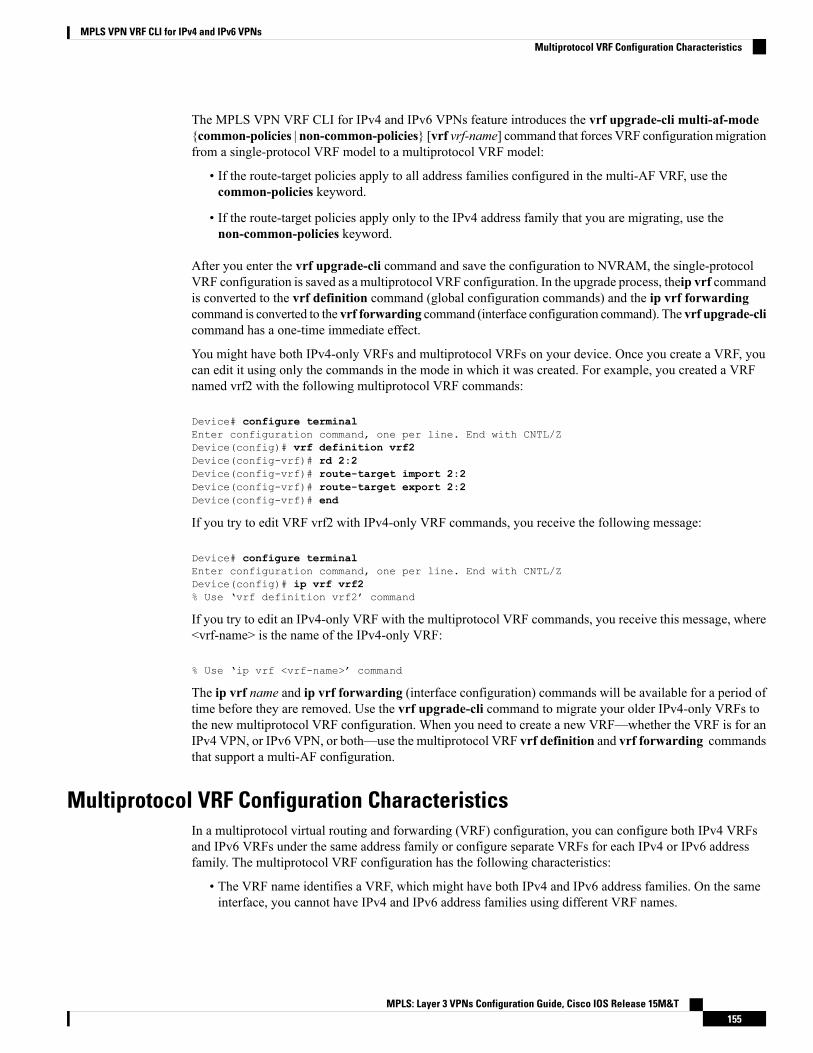
The MPLS VPN VRF CLI for IPv4 and IPv6 VPNs feature introduces the vrf upgrade-cli multi-af-mode{common-policies | non-common-policies} [vrf vrf-name] command that forces VRF configurationmigrationfrom a single-protocol VRF model to a multiprotocol VRF model:
• If the route-target policies apply to all address families configured in the multi-AF VRF, use thecommon-policies keyword.
• If the route-target policies apply only to the IPv4 address family that you are migrating, use thenon-common-policies keyword.
After you enter the vrf upgrade-cli command and save the configuration to NVRAM, the single-protocolVRF configuration is saved as a multiprotocol VRF configuration. In the upgrade process, theip vrf commandis converted to the vrf definition command (global configuration commands) and the ip vrf forwardingcommand is converted to the vrf forwarding command (interface configuration command). The vrf upgrade-clicommand has a one-time immediate effect.
You might have both IPv4-only VRFs and multiprotocol VRFs on your device. Once you create a VRF, youcan edit it using only the commands in the mode in which it was created. For example, you created a VRFnamed vrf2 with the following multiprotocol VRF commands:
Device# configure terminalEnter configuration command, one per line. End with CNTL/ZDevice(config)# vrf definition vrf2Device(config-vrf)# rd 2:2Device(config-vrf)# route-target import 2:2Device(config-vrf)# route-target export 2:2Device(config-vrf)# end
If you try to edit VRF vrf2 with IPv4-only VRF commands, you receive the following message:
Device# configure terminalEnter configuration command, one per line. End with CNTL/ZDevice(config)# ip vrf vrf2% Use ‘vrf definition vrf2’ command
If you try to edit an IPv4-only VRF with the multiprotocol VRF commands, you receive this message, where<vrf-name> is the name of the IPv4-only VRF:
% Use ‘ip vrf <vrf-name>’ command
The ip vrf name and ip vrf forwarding (interface configuration) commands will be available for a period oftime before they are removed. Use the vrf upgrade-cli command to migrate your older IPv4-only VRFs tothe new multiprotocol VRF configuration. When you need to create a new VRF—whether the VRF is for anIPv4 VPN, or IPv6 VPN, or both—use the multiprotocol VRF vrf definition and vrf forwarding commandsthat support a multi-AF configuration.
Multiprotocol VRF Configuration CharacteristicsIn a multiprotocol virtual routing and forwarding (VRF) configuration, you can configure both IPv4 VRFsand IPv6 VRFs under the same address family or configure separate VRFs for each IPv4 or IPv6 addressfamily. The multiprotocol VRF configuration has the following characteristics:
• The VRF name identifies a VRF, which might have both IPv4 and IPv6 address families. On the sameinterface, you cannot have IPv4 and IPv6 address families using different VRF names.
MPLS: Layer 3 VPNs Configuration Guide, Cisco IOS Release 15M&T155
MPLS VPN VRF CLI for IPv4 and IPv6 VPNsMultiprotocol VRF Configuration Characteristics

• The route distinguisher (RD), VPN ID, and Simple Network Management Protocol (SNMP) context areshared by both IPv4 and IPv6 address families for a given VRF.
• The policies (route target, for example) specified in multi-AF VRF mode, outside the address-familyconfiguration, are defaults to be applied to each address family. Route targets are the only VRFcharacteristics that can be defined inside and outside an address family.
The following is also true when you associate a multiprotocol VRF with an interface:
• Binding an interface to a VRF (vrf forwarding vrf-name command) removes all IPv4 and IPv6 addressesconfigured on that interface.
• Once you associate a VRF with a given interface, all active address families belong to that VRF. Theexception is when no address of the address-family type is configured, in which case the protocol isdisabled.
• Configuring an address on an interface that is bound to a VRF requires that the address familycorresponding to the address type is active for that VRF. Otherwise, an error message is issued statingthat the address family must be activated first in the VRF.
Backward compatibility with the single-protocol VRF CLI is supported in with the introduction of the MPLSVPN VRF CLI for IPv4 and IPv6 VPNs feature. This means that you might have single-protocol andmultiprotocol CLI on the same device, but not in the same VRF configuration.
The single-protocol CLI continues to allow you to define an IPv4 address within a VRF and an IPv6 addressin the global routing table on the same interface.
How to Configure MPLS VPN VRF CLI for IPv4 and IPv6 VPNs
Configuring a VRF for IPv4 and IPv6 MPLS VPNsPerform the following task to configure a virtual routing and forwarding (VRF) instance for IPv4 and IPv6Multiprotocol Label Switching (MPLS) Virtual Private Networks (VPNs). When you configure a VRF forboth IPv4 and IPv6 VPNs (a multiprotocol VRF), you can choose to configure route-target policies that applyto all address families in the VRF, or you can configure route-target policies that apply to individual addressfamilies in the VRF.
The following task shows how to configure a VRF that has that has route-target policies defined for IPv4 andIPv6 VPNs in separate VRF address families.
SUMMARY STEPS
1. enable2. configure terminal3. vrf definition vrf-name4. rd route-distinguisher5. address-family {ipv4 | ipv6}6. route-target {import | export | both} route-target-ext-community7. exit-address-family8. address-family {ipv4 | ipv6}
MPLS: Layer 3 VPNs Configuration Guide, Cisco IOS Release 15M&T156
MPLS VPN VRF CLI for IPv4 and IPv6 VPNsHow to Configure MPLS VPN VRF CLI for IPv4 and IPv6 VPNs

9. route-target {import | export | both} route-target-ext-community10. end
DETAILED STEPS
PurposeCommand or Action
Enables privileged EXEC mode.enableStep 1
Example: • Enter your password if prompted.
Device> enable
Enters global configuration mode.configure terminal
Example:
Step 2
Device# configure terminal
Configures a VRF routing table and enters VRFconfiguration mode.
vrf definition vrf-name
Example:
Step 3
• The vrf-name argument is the name of the VRF.Device(config)# vrf definition vrf1
Creates routing and forwarding tables for a VRF.rd route-distinguisherStep 4
Example: • The route-distinguisher argument specifies to add an8-byte value to an IPv4 prefix to create a VPN IPv4
Device(config-vrf)# rd 100:1 prefix. You can enter a route distinguisher in eitherof these formats:
• 16-bit autonomous system number (ASN): your32-bit number For example, 101:3.
• 32-bit IP address: your 16-bit number Forexample, 192.168.122.15:1.
Enters VRF address family configuration mode to specifyan address family for a VRF.
address-family {ipv4 | ipv6}
Example:
Step 5
• The ipv4 keyword specifies an IPv4 address familyfor a VRF.Device(config-vrf) address-family ipv4
• The ipv6 keyword specifies an IPv6 address familyfor a VRF.
Creates a route-target extended community for a VRF.route-target {import | export | both}route-target-ext-community
Step 6
• The import keyword specifies to import routinginformation from the target VPN extendedcommunity.
Example:
Device(config-vrf-af)# route-target both 100:2• The export keyword specifies to export routinginformation to the target VPN extended community.
MPLS: Layer 3 VPNs Configuration Guide, Cisco IOS Release 15M&T157
MPLS VPN VRF CLI for IPv4 and IPv6 VPNsConfiguring a VRF for IPv4 and IPv6 MPLS VPNs
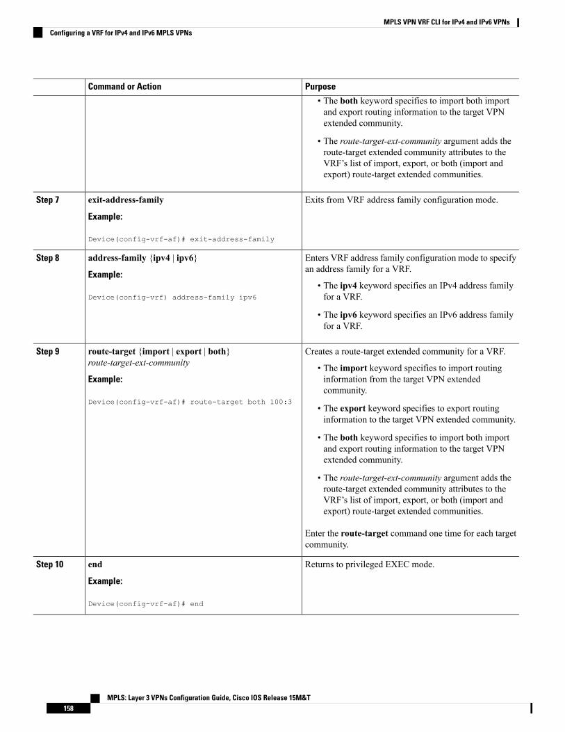
PurposeCommand or Action
• The both keyword specifies to import both importand export routing information to the target VPNextended community.
• The route-target-ext-community argument adds theroute-target extended community attributes to theVRF’s list of import, export, or both (import andexport) route-target extended communities.
Exits from VRF address family configuration mode.exit-address-family
Example:
Step 7
Device(config-vrf-af)# exit-address-family
Enters VRF address family configuration mode to specifyan address family for a VRF.
address-family {ipv4 | ipv6}
Example:
Step 8
• The ipv4 keyword specifies an IPv4 address familyfor a VRF.Device(config-vrf) address-family ipv6
• The ipv6 keyword specifies an IPv6 address familyfor a VRF.
Creates a route-target extended community for a VRF.route-target {import | export | both}route-target-ext-community
Step 9
• The import keyword specifies to import routinginformation from the target VPN extendedcommunity.
Example:
Device(config-vrf-af)# route-target both 100:3• The export keyword specifies to export routinginformation to the target VPN extended community.
• The both keyword specifies to import both importand export routing information to the target VPNextended community.
• The route-target-ext-community argument adds theroute-target extended community attributes to theVRF’s list of import, export, or both (import andexport) route-target extended communities.
Enter the route-target command one time for each targetcommunity.
Returns to privileged EXEC mode.end
Example:
Step 10
Device(config-vrf-af)# end
MPLS: Layer 3 VPNs Configuration Guide, Cisco IOS Release 15M&T158
MPLS VPN VRF CLI for IPv4 and IPv6 VPNsConfiguring a VRF for IPv4 and IPv6 MPLS VPNs

Associating a Multiprotocol VRF with an InterfacePerform the following task to associate a multiprotocol virtual routing and forwarding (VRF) instance withan interface. Associating the VRF with an interface activates the VRF.
SUMMARY STEPS
1. enable2. configure terminal3. interface type number4. vrf forwarding vrf-name5. ip address ip-address mask [ secondary]6. ipv6 address {ipv6-address/prefix-length | prefix-name sub-bits/prefix-length}7. end
DETAILED STEPS
PurposeCommand or Action
Enables privileged EXEC mode.enableStep 1
Example: • Enter your password if prompted.
Device> enable
Enters global configuration mode.configure terminal
Example:
Step 2
Device# configure terminal
Configures an interface type and enters interfaceconfiguration mode.
interface type number
Example:
Step 3
• The type argument identifies the type of interface tobe configured.Device(config)# interface Ethernet 0/1
• The number argument identifies the port, connector,or interface card number.
Associates a VRF with an interface or subinterface.vrf forwarding vrf-nameStep 4
Example: • The vrf-name argument is the name of the VRF.
Device(config-if)# vrf forwarding vrf1
Sets a primary or secondary IP address for an interface.ip address ip-address mask [ secondary]Step 5
Example: • The ip-address argument is the IP address.
Device(config-if)# ip address 10.24.24.24255.255.255.255
• The mask argument is the mask of the associated IPsubnet.
• The secondary keyword specifies that the configuredaddress is a secondary IP address. If this keyword is
MPLS: Layer 3 VPNs Configuration Guide, Cisco IOS Release 15M&T159
MPLS VPN VRF CLI for IPv4 and IPv6 VPNsAssociating a Multiprotocol VRF with an Interface

PurposeCommand or Action
omitted, the configured address is the primary IPaddress.
Configures an IPv6 address based on an IPv6 general prefixand enables IPv6 processing on an interface.
ipv6 address {ipv6-address/prefix-length | prefix-namesub-bits/prefix-length}
Step 6
Example: • The ipv6-address argument is the IPv6 address to beused.
Device(config-if)# ipv6 address2001:0DB8:0300:0201::/64 • The prefix-length argument is the length of the IPv6
prefix, which is a decimal value that indicates howmany of the high-order contiguous bits of the addresscomprise the prefix (the network portion of theaddress). A slashmarkmust precede the decimal value.
• The prefix-name argument is a general prefix thatspecifies the leading bits of the network to beconfigured on the interface.
• The sub-bits argument is the subprefix bits and hostbits of the address to be concatenated with the prefixesprovided by the general prefix specified with theprefix-name argument.
The sub-bits argument must be in the form documented inRFC 2373 where the address is specified in hexadecimalusing 16-bit values between colons.
Returns to privileged EXEC mode.end
Example:
Step 7
Device(config-if) end
Verifying the MPLS VPN VRF CLI for IPv4 and IPv6 VPNs ConfigurationPerform the following task to verify the MPLS VPNVRF CLI for IPv4 and IPv6 VPNs feature configuration,that is, to show that the virtual routing and forwarding (VRF) configuration is upgraded to a multi-AFmultiprotocol VRF.
SUMMARY STEPS
1. enable2. show running-config vrf [vrf-name]3. show vrf4. show vrf detail [vrf-name]5. exit
MPLS: Layer 3 VPNs Configuration Guide, Cisco IOS Release 15M&T160
MPLS VPN VRF CLI for IPv4 and IPv6 VPNsVerifying the MPLS VPN VRF CLI for IPv4 and IPv6 VPNs Configuration

DETAILED STEPS
Step 1 enable
Enables privileged EXEC mode. Enter your password, if prompted. For example:
Example:
Device> enableDevice#
Step 2 show running-config vrf [vrf-name]
Verifies that the upgrade to a multi-AFmultiprotocol VRF configuration was successful. The following is sample commandoutput before the upgrade to a multi-AF multiprotocol VRF:
Example:
Device# show running-config vrf vpn2
Building configuration...Current configuration : 604 bytesip vrf vpn2rd 1:1route-target both 1:1!!interface Loopback1ip vrf forwarding vpn2ip address 10.43.43.43 255.255.255.255!
The following is sample command output after you upgrade to a multi-AF multiprotocol VRF with common policies forall address families:
Example:
Device# show running-config vrf vpn1
Building configuration...Current configuration : 604 bytesvrf definition vpn1rd 1:1route-target both 1:1!address-family 1pv4exit-address-family!!interface Loopback1ip vrf forwarding vpn1ip address 10.43.43.43 255.255.255.255!
This configuration contains the vrf definition command. The vrf definition command replaces the ip vrf command inthe multi-AF multiprotocol VRF configuration.
Step 3 show vrf
MPLS: Layer 3 VPNs Configuration Guide, Cisco IOS Release 15M&T161
MPLS VPN VRF CLI for IPv4 and IPv6 VPNsVerifying the MPLS VPN VRF CLI for IPv4 and IPv6 VPNs Configuration

Verifies that the upgrade to a multi-AFmultiprotocol VRF configuration was successful. The show vrf command replacesthe show ip vrf command when a VRF configuration is updated to a multi-AF multiprotocol VRF configuration. Theshow vrf command displays the protocols defined for a VRF. The following command shows sample output after youupgrade a single-protocol VRF configuration to a multi-AF multiprotocol VRF configuration:
Example:
Device# show vrf vpn1
Name Default RD Protocols Interfacesvpn1 1:1 ipv4 Lo1/0
The following is sample output from the show ip vrf vp1 command. Compare this to the output of the show vrf vpn1command. The protocols under the VRF are not displayed.
Example:
Device# show ip vrf vrf1
Name Default RD Interfacevpn1 1:1 Loopback1
The following is sample output from the show vrf command for multiprotocol VRFs, one of which contains both IPv4and IPv6 protocols:
Example:
Device# show vrf
Name Default RD Protocols Interfacesvpn1 1:1 ipv4 Lo1/0vpn2 100:3 ipv4 Lo23 AT3/0/0.1vpn4 100:2 ipv4,ipv6
Step 4 show vrf detail [vrf-name]
Displays all characteristics of the defined VRF to verify that the configuration is as you expected. For example, if yourVRF configuration for VRF vpn1 is as follows:
Example:
vrf definition vpn1route-target both 100:1route-target import 100:2!address-family ipv4exit-address-family!address-family ipv6route-target both 100:1route-target import 100:3exit-address-family
This command displays the following:
Example:
Device# show vrf detail vpn1
VRF vpn1 (VRF Id = 3); default RD <not set>; default VPNID <not set>
MPLS: Layer 3 VPNs Configuration Guide, Cisco IOS Release 15M&T162
MPLS VPN VRF CLI for IPv4 and IPv6 VPNsVerifying the MPLS VPN VRF CLI for IPv4 and IPv6 VPNs Configuration

No interfacesAddress family ipv4 (Table ID = 3 (0x3)):Connected addresses are not in global routing tableExport VPN route-target communitiesRT:100:1
Import VPN route-target communitiesRT:100:1 RT:100:2
No import route-mapNo export route-mapVRF label distribution protocol: not configuredVRF label allocation mode: per-prefix
Address family ipv6 (Table ID = 503316483 (0x1E000003)):Connected addresses are not in global routing tableExport VPN route-target communitiesRT:100:1
Import VPN route-target communitiesRT:100:1 RT:100:3
No import route-mapNo export route-mapVRF label distribution protocol: not configuredVRF label allocation mode: per-prefix
Step 5 exit
Returns to user EXEC mode. For example:
Example:
Device# exitDevice>
Migrating from a Single-Protocol IPv4-Only VRF to a Multiprotocol VRFConfiguration
Perform the following task to force migration from a single-protocol IPv4-only virtual routing and forwarding(VRF) configuration to a multiprotocol VRF configuration.
The multiprotocol VRF configuration allows you to define multiple address families under the same VRF. Agiven VRF, identified by its name and a set of policies, can apply to both an IPv4 VPN and an IPv6 VPN atthe same time. This VRF can be activated on a given interface, even though the routing and forwarding tablesare different for the IPv4 and IPv6 protocols.
SUMMARY STEPS
1. enable2. configure terminal3. vrf upgrade-cli multi-af-mode {common-policies | non-common-policies} [vrf vrf-name]4. exit5. show running-config vrf [vrf-name]
MPLS: Layer 3 VPNs Configuration Guide, Cisco IOS Release 15M&T163
MPLS VPN VRF CLI for IPv4 and IPv6 VPNsMigrating from a Single-Protocol IPv4-Only VRF to a Multiprotocol VRF Configuration

DETAILED STEPS
PurposeCommand or Action
Enables privileged EXEC mode.enableStep 1
Example: • Enter your password if prompted.
Device> enable
Enters global configuration mode.configure terminal
Example:
Step 2
Device# configure terminal
Upgrades a VRF instance or all VRFs configured on thedevice to support multiple address families under the sameVRF.
vrf upgrade-cli multi-af-mode {common-policies |non-common-policies} [vrf vrf-name]
Example:
Step 3
• Themulti-af-mode keyword specifies an upgrade ofa single-protocol VRF or all VRFs to a multiprotocolVRF that supports multi-AFs configuration.
Device(config)# vrf upgrade-cli multi-af-modecommon-policies vrf vpn4
• The common-policies keyword specifies to copy theroute-target policies to the common part of the VRFconfiguration so that the policies apply to all addressfamilies configured in the multi-AF VRF.
• The non-common-policies keyword specifies to copythe route-target policies to the IPv4 address family partof the VRF configuration so that the policies applyonly to IPv4.
• The vrf keyword specifies a VRF for the upgrade toa multi-AF VRF configuration.
• The vrf-name argument is the name of thesingle-protocol VRF to upgrade to a multi-AF VRFconfiguration.
Exits to privileged EXEC mode.exit
Example:
Step 4
Device(config)# exit
Displays the subset of the running configuration of a devicethat is linked to a specific VRF instance or to all VRFsconfigured on the device.
show running-config vrf [vrf-name]
Example:
Device# show running-config vrf vpn4
Step 5
• The vrf-name argument is the name of the VRF ofwhich you want to display the configuration.
MPLS: Layer 3 VPNs Configuration Guide, Cisco IOS Release 15M&T164
MPLS VPN VRF CLI for IPv4 and IPv6 VPNsMigrating from a Single-Protocol IPv4-Only VRF to a Multiprotocol VRF Configuration

PurposeCommand or Action
The Cisco software image that supports themultiprotocol VRF commandsmight not supportthe show running-config vrf command. Youcan use the show running-config commandinstead.
Note
Configuration Examples for MPLS VPN VRF CLI for IPv4 and IPv6VPNs
Example: Multiprotocol VRF Configuration Single Protocol with NoncommonPolicies
The following is an example of a multiprotocol virtual routing and forwarding (VRF) configuration for asingle protocol (IPv4) with route-target policies in the address family configuration:
vrf definition vrf2rd 2:2!address-family ipv4route-target export 2:2route-target import 2:2exit-address-family
The RD (2:2) applies to all address families defined for VRF vrf2.
Example: Multiprotocol VRF Configuration Multiprotocol with NoncommonPolicies
The following is an example of a multiprotocol virtual routing and forwarding (VRF) configuration for IPv4and IPv6 Virtual Private Networks (VPNs) in which the route-target policies are defined in the separate addressfamily configurations:
vrf definition vrf2rd 2:2!address-family ipv4route-target export 2:2route-target import 2:2exit-address-family!address-family ipv6route-target export 3:3route-target import 3:3exit-address-family
MPLS: Layer 3 VPNs Configuration Guide, Cisco IOS Release 15M&T165
MPLS VPN VRF CLI for IPv4 and IPv6 VPNsConfiguration Examples for MPLS VPN VRF CLI for IPv4 and IPv6 VPNs

Example:MultiprotocolVRFConfigurationMultiprotocolwithCommonPoliciesThe following is an example of a multiprotocol virtual routing and forwarding (VRF) configuration for IPv4and IPv6 Virtual Private Networks (VPNs) with route-target policies defined in the global part of the VRF:
vrf definition vrf2rd 2:2route-target export 2:2route-target import 2:2!address-family ipv4exit-address-family!address-family ipv6exit-address-family
The route-target policies are defined outside the address family configurations. Therefore, the policies applyto all address families defined in VRF vrf2.
Example: Multiprotocol VRF Configuration Multiprotocol with Common andNoncommon Policies
The following is an example of a multiprotocol virtual routing and forwarding (VRF) configuration withroute-target policies defined in both global and address family areas:
• For IPv6, the route-target definitions are defined under the address family. These definitions are usedand the route-target definitions in the global area are ignored. Therefore, the IPv6 Virtual Private Network(VPN) ignores import 100:2.
• For IPv4, no route-target policies are defined under the address family, therefore, the global definitionsare used.
vrf definition vfr1route-target export 100:1route-target import 100:1route-target import 100:2!address-family ipv4exit-address-family!address-family ipv6route-target export 100:1route-target import 100:1route-target import 100:3exit-address-family
Examples: Configuring a VRF for IPv4 and IPv6 VPNsThe following example shows how to configure a virtual routing and forwarding (VRF) instance for IPv4 andIPv6 Virtual Private Networks (VPNs):
configure terminal!vrf definition vrf1rd 100:1
MPLS: Layer 3 VPNs Configuration Guide, Cisco IOS Release 15M&T166
MPLS VPN VRF CLI for IPv4 and IPv6 VPNsExample: Multiprotocol VRF Configuration Multiprotocol with Common Policies

!address-family ipv4route-target both 100:2exit-address-family!address-family ipv6route-target both 100:3exit-address-family
In this example, noncommon policies are defined in the address family configuration.
The following is an example of a VRF for IPv4 and IPv6 that has common policies defined in the global partof the VRF configuration:
configure terminal!vrf definition vrf2rd 200:1route-target both 200:2!address-family ipv4exit-address-family!address-family ipv6exit-address-familyend
Example: Associating a Multiprotocol VRF with an InterfaceThe following example shows how to associate a multiprotocol virtual routing and forwarding (VRF) instancewith an interface:
configure terminal!interface Ethernet 0/1vrf forwarding vrf1ip address 10.24.24.24 255.255.255.255ipv6 address 2001:0DB8:0300:0201::/64end
Examples: Migrating from a Single-Protocol IPv4-Only VRF Configuration to aMultiprotocol VRF Configuration
This section contains examples that show how to migrate from a single-protocol IPv4-only virtual routingand forwarding (VRF) configuration to a multiprotocol VRF configuration.
This example shows a single-protocol IPv4-only VRF before the VRF CLI for IPv4 and IPv6 is entered onthe device:
ip vrf vrf1rd 1:1route-target both 1:1interface Loopback1ip vrf forwarding V1ip address 10.3.3.3 255.255.255.255
MPLS: Layer 3 VPNs Configuration Guide, Cisco IOS Release 15M&T167
MPLS VPN VRF CLI for IPv4 and IPv6 VPNsExample: Associating a Multiprotocol VRF with an Interface

This example shows how to force the migration of the single-protocol VRF vrf1 to a multiprotocol VRFconfiguration:
Device# configure terminalEnter configuration commands, one per line. End with CNTL/Z.!Device(config)# vrf upgrade-cli multi-af-mode common-policies vrf vrf1You are about to upgrade to the multi-AF VRF syntax commands.You will loose any IPv6 address configured on interfacesbelonging to upgraded VRFs.Are you sure ? [yes]: yesNumber of VRFs upgraded: 1Device(config)# exit
This example shows the multiprotocol VRF configuration after the forced migration:
vrf definition vrf1rd 1:1route-target both 1:1!address-family ipv4exit-address-family!interface Loopback1vrf forwarding V1ip address 10.3.3.3 255.255.255.255
The following is another example of a multi-AF multiprotocol VRF configuration:
vrf definition vrf2rd 100:1address family ipv6route-target both 200:1exit-address-family!ip vrf vrf1rd 200:1route-target both 200:1!interface Ethernet0/0vrf forwarding vrf2ip address 10.50.1.2 255.255.255.0ipv6 address 2001:0DB8:0:1::/64!interface Ethernet0/1ip vrf forwarding vrf1ip address 10.60.1.2 255.255.255.0ipv6 address 2001:0DB8:1 :1::/64
In this example, all addresses (IPv4 and IPv6) defined for interface Ethernet0/0 are in VRF vrf2. For theinterface Ethernet0/1, the IPv4 address is defined in VRF vrf1 but the IPv6 address is in the global IPv6 routingtable.
MPLS: Layer 3 VPNs Configuration Guide, Cisco IOS Release 15M&T168
MPLS VPN VRF CLI for IPv4 and IPv6 VPNsExamples: Migrating from a Single-Protocol IPv4-Only VRF Configuration to a Multiprotocol VRF Configuration

Additional ReferencesRelated Documents
Document TitleRelated Topic
Cisco Master Command List, All ReleasesCisco IOS commands
Cisco IOSMultiprotocol Label Switching Command ReferenceMPLS and MPLS applications commands
Standards and RFCs
TitleStandard/RFC
A Border Gateway Protocol 4 (BGP-4)RFC 1771
BGP MPLS/IP Virtual Private Networks (VPNs)RFC 4364
Technical Assistance
LinkDescription
http://www.cisco.com/cisco/web/support/index.htmlTheCisco Support andDocumentationwebsite providesonline resources to download documentation, software,and tools. Use these resources to install and configurethe software and to troubleshoot and resolve technicalissues with Cisco products and technologies. Access tomost tools on the Cisco Support and Documentationwebsite requires a Cisco.com user ID and password.
Feature Information for MPLS VPN VRF CLI for IPv4 and IPv6VPNs
The following table provides release information about the feature or features described in this module. Thistable lists only the software release that introduced support for a given feature in a given software releasetrain. Unless noted otherwise, subsequent releases of that software release train also support that feature.
Use Cisco Feature Navigator to find information about platform support and Cisco software image support.To access Cisco Feature Navigator, go to www.cisco.com/go/cfn. An account on Cisco.com is not required.
MPLS: Layer 3 VPNs Configuration Guide, Cisco IOS Release 15M&T169
MPLS VPN VRF CLI for IPv4 and IPv6 VPNsAdditional References

Table 9: Feature Information for MPLS VPN VRF CLI for IPv4 and IPv6 VPNs
Feature InformationReleasesFeature Name
This document describes how to configure a multiprotocol VirtualPrivate Network (VPN) routing and forwarding (VRF) instance forIPv4 and IPv6 VPNs and describes how to upgrade your existingsingle-protocol IPv4-only VRF to a multiprotocol VRF configuration.
The MPLS VPN VRF CLI for IPv4 and IPv6 VPNs feature introducescommands that allow you to enable an IPv4 and IPv6 VPN in the sameMultiprotocol Label Switching (MPLS) VRF configuration and tosimplify the migration from a single-protocol VRF configuration to amultiprotocol VRF configuration.
In Cisco IOS Release 12.2(33)SB, this feature was introduced on theCisco 10000 series router.
In Cisco IOS Release 12.2(33)SRB, this feature was implemented onthe Cisco 7600 series router.
In Cisco IOS Release 12.2(33)SXI, this feature was integrated.
In Cisco IOS Release 12.4(2)T, this feature was integrated.
In Cisco IOS XE Release 3.1S, this feature was implemented on theCisco ASR 1000 Series Aggregation Services Routers.
12.2(33)SB
12.2(33)SRB
12.2(33)SXI
12.4(20)T
Cisco IOS XERelease 3.1S
MPLS VPNVRF CLI forIPv4 and IPv6VPNs
The following commands were introduced or modified: show vrf, vrfdefinition, vrf forwarding, vrf upgrade-cli.
Glossary6PE—IPv6 provider edge device or a Multiprotocol Label Switching (MPLS) label switch router (LSR) edgerouter using IPv6.
6VPE—IPv6 Virtual Private Network (VPN) provider edge device.
AF—address family. Set of related communication protocols in which all members use a common addressingmechanism to identify endpoints. Also called protocol family.
AFI—Address Family Identifier. Carries the identity of the network-layer protocol that is associated with thenetwork address.
BGP—Border Gateway Protocol. A routing protocol used between autonomous systems. It is the routingprotocol that makes the internet work. BGP is a distance-vector routing protocol that carries connectivityinformation and an additional set of BGP attributes. These attributes allow for a set of policies for decidingthe best route to use to reach a given destination. BGP is defined by RFC 1771.
CE—customer edge device. A service provider device that connects to Virtual Private Network (VPN)customer sites.
FIB—Forwarding Information Base. Database that stores information about switching of data packets. A FIBis based on information in the Routing Information Base (RIB). It is the optimal set of selected routes that areinstalled in the line cards for forwarding.
MPLS: Layer 3 VPNs Configuration Guide, Cisco IOS Release 15M&T170
MPLS VPN VRF CLI for IPv4 and IPv6 VPNsGlossary

HA—high availability. High availability is defined as the continuous operation of systems. For a system tobe available, all components--including application and database servers, storage devices, and the end-to-endnetwork--need to provide continuous service.
IP—Internet Protocol. Network-layer protocol in the TCP/IP stack offering a connectionless internetworkservice. IP provides features for addressing, type-of-service specification, fragmentation and reassembly, andsecurity.
IPv4—IP Version 4. Network layer for the TCP/IP protocol suite. IPv4 is a connectionless, best-effort packetswitching protocol.
IPv6—IPVersion 6. Replacement for IPv4. IPv6 is a next-generation IP protocol. IPv6 is backward compatiblewith and designed to fix the shortcomings of IPv4, such as data security and maximum number of useraddresses. IPv6 increases the address space from 32 to 128 bits, providing for an unlimited number of networksand systems. It also supports quality of service (QoS) parameters for real-time audio and video.
MFI—MPLS Forwarding Infrastructure. In the Cisco MPLS subsystem, the data structure for storinginformation about incoming and outgoing labels and associated equivalent packets suitable for labeling.
MPLS—Multiprotocol Label Switching.MPLS is amethod for forwarding packets (frames) through a network.It enables devices at the edge of a network to apply labels to packets (frames). ATM switches or existingdevices in the network core can switch packets according to the labels with minimal lookup overhead.
PE—provider edge device. A device that is part of a service provider’s network and that is connected to acustomer edge (CE) device. The PE device function is a combination of an MLS edge label switch router(LSR) function with some additional functions to support Virtual Private Networks (VPNs).
RD (IPv4)—route distinguisher. An 8-byte value that is concatenated with an IPv4 prefix to create a uniqueVPN IPv4 (VPNv4) prefix.
RD (IPv6)—route distinguisher. A 64-bit value that is prepended to an IPv6 prefix to create a globally uniqueVPN-IPv6 address.
RIB—Routing Information Base. The set of all available routes from which to choose the ForwardingInformation Base (FIB). The RIB essentially contains all routes available for selection. It is the sum of allroutes learned by dynamic routing protocols, all directly attached networks (that is-networks to which a givendevice has interfaces connected), and any additional configured routes, such as static routes.
RT—route target. Extended community attribute used to identify the Virtual Private Network (VPN) routingand forwarding (VRF) routing table into which a prefix is to be imported.
VPN—Virtual Private Network. Enables IP traffic to travel securely over a public TCP/IP network byencrypting all traffic from one network to another. A VPN uses “tunneling” to encrypt all information at theIP level.
VRF—Virtual Private Network (VPN) routing and forwarding instance. A VRF consists of an IP routingtable, a derived forwarding table, a set of interfaces that use the forwarding table, and a set of rules and routingprotocols that determine what goes into the forwarding table. In general, a VRF includes the routing informationthat defines a customer VPN site that is attached to a PE device.
VRF table—A routing and a forwarding table associated to a Virtual Private Network (VPN) routing andforwarding (VRF) instance. This is a customer-specific table, enabling the provider edge (PE) device tomaintain independent routing states for each customer.
MPLS: Layer 3 VPNs Configuration Guide, Cisco IOS Release 15M&T171
MPLS VPN VRF CLI for IPv4 and IPv6 VPNsGlossary

MPLS: Layer 3 VPNs Configuration Guide, Cisco IOS Release 15M&T172
MPLS VPN VRF CLI for IPv4 and IPv6 VPNsGlossary

C H A P T E R 11MPLS VPN Route Target Rewrite
The MPLS VPN Route Target Rewrite feature allows the replacement of route targets on incoming andoutgoing Border Gateway Protocol (BGP) updates. Typically, Autonomous System Border Routers (ASBRs)perform the replacement of route targets at autonomous system boundaries. Route Reflectors (RRs) andprovider edge (PE) devices can also perform route target replacement.
The main advantage of the MPLS VPN Route Target Rewrite feature is that it keeps the administration ofrouting policy local to the autonomous system.
• Finding Feature Information, on page 173• Prerequisites for MPLS VPN Route Target Rewrite, on page 173• Restrictions for MPLS VPN Route Target Rewrite, on page 174• Information About MPLS VPN Route Target Rewrite, on page 174• How to Configure MPLS VPN Route Target Rewrite, on page 176• Configuration Examples for MPLS VPN Route Target Rewrite, on page 187• Additional References, on page 189• Feature Information for MPLS VPN Route Target Rewrite, on page 189• Glossary, on page 191
Finding Feature InformationYour software release may not support all the features documented in this module. For the latest caveats andfeature information, see Bug Search Tool and the release notes for your platform and software release. Tofind information about the features documented in this module, and to see a list of the releases in which eachfeature is supported, see the feature information table.
Use Cisco Feature Navigator to find information about platform support and Cisco software image support.To access Cisco Feature Navigator, go to www.cisco.com/go/cfn. An account on Cisco.com is not required.
Prerequisites for MPLS VPN Route Target Rewrite• You should know how to configure Multiprotocol Label Switching (MPLS) Virtual Private Networks(VPNs).
• You need to configure your network to support interautonomous systems with different route target (RT)values in each autonomous system.
MPLS: Layer 3 VPNs Configuration Guide, Cisco IOS Release 15M&T173

• You need to identify the RT replacement policy and target device for each autonomous system.
Restrictions for MPLS VPN Route Target RewriteYou can apply multiple replacement rules using the route-map continue clause. The MPLS VPN Route TargetRewrite feature does not support the continue clause on outbound route maps.
Information About MPLS VPN Route Target Rewrite
Route Target Replacement PolicyRouting policies for a peer include all configurations that may impact inbound or outbound routing tableupdates. The MPLS VPN Route Target Rewrite feature can influence routing table updates by allowing thereplacement of route targets on inbound and outbound Border Gateway Protocol (BGP) updates. Route targetsare carried as extended community attributes in BGP Virtual Private Network IP Version 4 (VPNv4) updates.Route target extended community attributes are used to identify a set of sites and VPN routing and forwarding(VRF) instances that can receive routes with a configured route target.
In general, autonomous system border routers (ASBRs) perform route target replacement at autonomoussystem borders when the ASBRs exchange VPNv4 prefixes. You can also configure the MPLS VPN RouteTarget Rewrite feature on provider edge (PE) devices and Route Reflector (RR) devices.
The figure below shows an example of route target replacement on ASBRs in anMultiprotocol Label Switching(MPLS) VPN interautonomous system topology. This example includes the following configurations:
• PE1 is configured to import and export RT 100:1 for VRF VPN1.
• PE2 is configured to import and export RT 200:1 for VRF VPN2.
• ASBR1 is configured to rewrite all inbound VPNv4 prefixes with RT 200:1 to RT 100:1.
• ASBR2 is configured to rewrite all inbound VPNv4 prefixes with RT 100:1 to RT 200:1.
MPLS: Layer 3 VPNs Configuration Guide, Cisco IOS Release 15M&T174
MPLS VPN Route Target RewriteRestrictions for MPLS VPN Route Target Rewrite
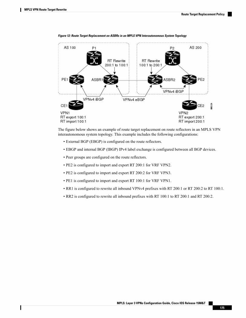
Figure 12: Route Target Replacement on ASBRs in an MPLS VPN Interautonomous System Topology
The figure below shows an example of route target replacement on route reflectors in an MPLS VPNinterautonomous system topology. This example includes the following configurations:
• External BGP (EBGP) is configured on the route reflectors.
• EBGP and internal BGP (IBGP) IPv4 label exchange is configured between all BGP devices.
• Peer groups are configured on the route reflectors.
• PE2 is configured to import and export RT 200:1 for VRF VPN2.
• PE2 is configured to import and export RT 200:2 for VRF VPN3.
• PE1 is configured to import and export RT 100:1 for VRF VPN1.
• RR1 is configured to rewrite all inbound VPNv4 prefixes with RT 200:1 or RT 200:2 to RT 100:1.
• RR2 is configured to rewrite all inbound prefixes with RT 100:1 to RT 200:1 and RT 200:2.
MPLS: Layer 3 VPNs Configuration Guide, Cisco IOS Release 15M&T175
MPLS VPN Route Target RewriteRoute Target Replacement Policy

Figure 13: Route Target Rewrite on Route Reflectors in an MPLS VPN Interautonomous System Topology
Route Maps and Route Target ReplacementTheMPLSVPNRoute Target Rewrite feature extends the Border Gateway Protocol (BGP) inbound/outboundroute map functionality to enable route target replacement. The set extcomm-list delete command entered inroute-map configuration mode allows the deletion of a route target extended community attribute based onan extended community list.
How to Configure MPLS VPN Route Target Rewrite
Configuring a Route Target Replacement PolicyPerform this task to configure a route target (RT) replacement policy for your internetwork.
If you configure a provider edge (PE) device to rewrite RT x to RT y and the PE has a virtual routing andforwarding (VRF) instance that imports RT x , you need to configure the VRF to import RT y in addition toRT x .
SUMMARY STEPS
1. enable2. configure terminal3. ip extcommunity-list {standard-list-number | expanded-list-number} {permit | deny} [regular-expression]
[rt | soo extended-community-value]4. route-map map-name [permit | deny] [sequence-number]
MPLS: Layer 3 VPNs Configuration Guide, Cisco IOS Release 15M&T176
MPLS VPN Route Target RewriteRoute Maps and Route Target Replacement
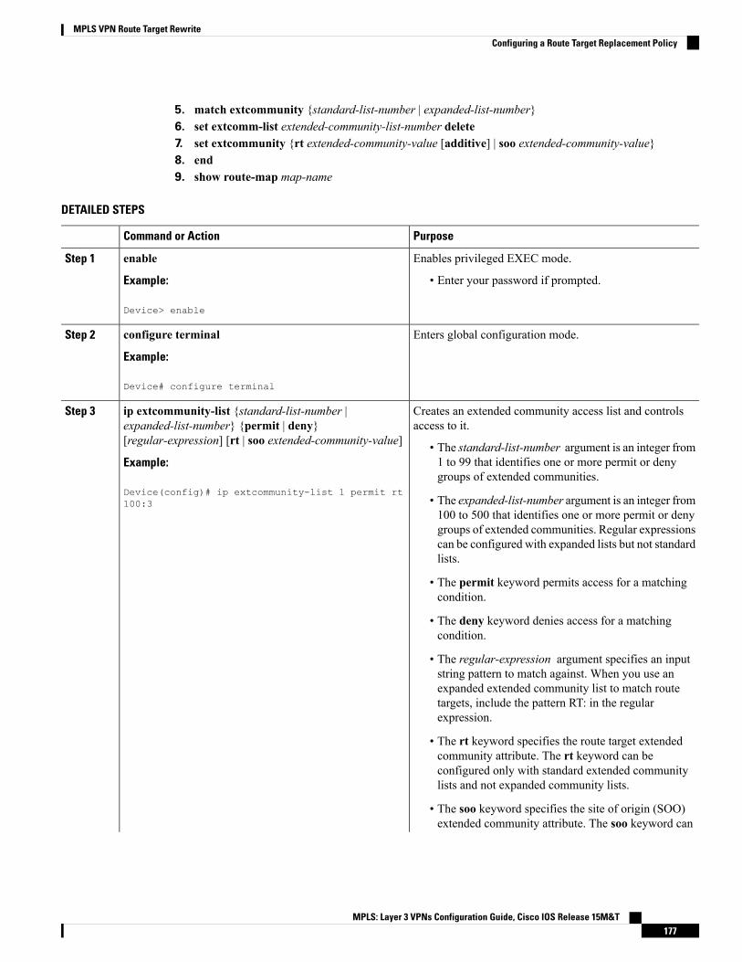
5. match extcommunity {standard-list-number | expanded-list-number}6. set extcomm-list extended-community-list-number delete7. set extcommunity {rt extended-community-value [additive] | soo extended-community-value}8. end9. show route-map map-name
DETAILED STEPS
PurposeCommand or Action
Enables privileged EXEC mode.enableStep 1
Example: • Enter your password if prompted.
Device> enable
Enters global configuration mode.configure terminal
Example:
Step 2
Device# configure terminal
Creates an extended community access list and controlsaccess to it.
ip extcommunity-list {standard-list-number |expanded-list-number} {permit | deny}[regular-expression] [rt | soo extended-community-value]
Step 3
• The standard-list-number argument is an integer from1 to 99 that identifies one or more permit or denygroups of extended communities.
Example:
Device(config)# ip extcommunity-list 1 permit rt100:3 • The expanded-list-number argument is an integer from
100 to 500 that identifies one or more permit or denygroups of extended communities. Regular expressionscan be configured with expanded lists but not standardlists.
• The permit keyword permits access for a matchingcondition.
• The deny keyword denies access for a matchingcondition.
• The regular-expression argument specifies an inputstring pattern to match against. When you use anexpanded extended community list to match routetargets, include the pattern RT: in the regularexpression.
• The rt keyword specifies the route target extendedcommunity attribute. The rt keyword can beconfigured only with standard extended communitylists and not expanded community lists.
• The soo keyword specifies the site of origin (SOO)extended community attribute. The soo keyword can
MPLS: Layer 3 VPNs Configuration Guide, Cisco IOS Release 15M&T177
MPLS VPN Route Target RewriteConfiguring a Route Target Replacement Policy
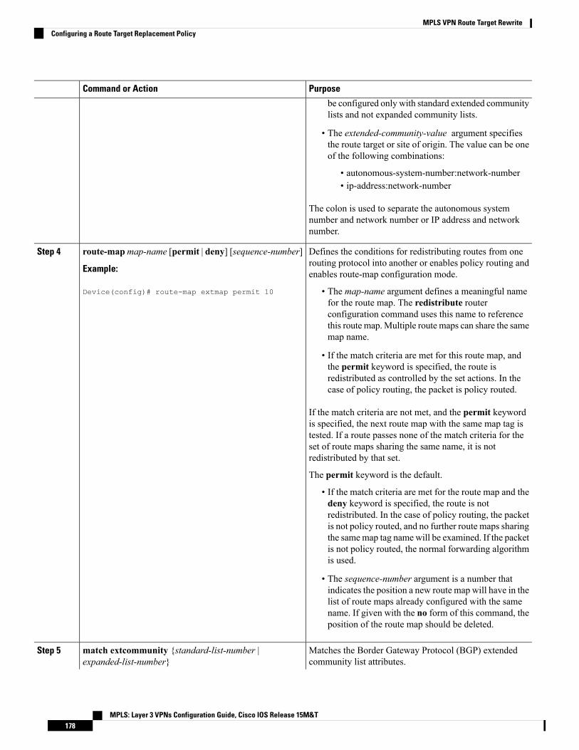
PurposeCommand or Action
be configured only with standard extended communitylists and not expanded community lists.
• The extended-community-value argument specifiesthe route target or site of origin. The value can be oneof the following combinations:
• autonomous-system-number:network-number• ip-address:network-number
The colon is used to separate the autonomous systemnumber and network number or IP address and networknumber.
Defines the conditions for redistributing routes from onerouting protocol into another or enables policy routing andenables route-map configuration mode.
route-mapmap-name [permit | deny] [sequence-number]
Example:
Device(config)# route-map extmap permit 10
Step 4
• The map-name argument defines a meaningful namefor the route map. The redistribute routerconfiguration command uses this name to referencethis route map.Multiple route maps can share the samemap name.
• If the match criteria are met for this route map, andthe permit keyword is specified, the route isredistributed as controlled by the set actions. In thecase of policy routing, the packet is policy routed.
If the match criteria are not met, and the permit keywordis specified, the next route map with the same map tag istested. If a route passes none of the match criteria for theset of route maps sharing the same name, it is notredistributed by that set.
The permit keyword is the default.
• If the match criteria are met for the route map and thedeny keyword is specified, the route is notredistributed. In the case of policy routing, the packetis not policy routed, and no further route maps sharingthe samemap tag name will be examined. If the packetis not policy routed, the normal forwarding algorithmis used.
• The sequence-number argument is a number thatindicates the position a new route map will have in thelist of route maps already configured with the samename. If given with the no form of this command, theposition of the route map should be deleted.
Matches the Border Gateway Protocol (BGP) extendedcommunity list attributes.
match extcommunity {standard-list-number |expanded-list-number}
Step 5
MPLS: Layer 3 VPNs Configuration Guide, Cisco IOS Release 15M&T178
MPLS VPN Route Target RewriteConfiguring a Route Target Replacement Policy

PurposeCommand or Action
Example: • The standard-list-number argument is a number from1 to 99 that identifies one or more permit or denygroups of extended community attributes.Device(config-route-map)# match extcommunity 1
Example: • The expanded-list-number argument is a number from100 to 500 that identifies one or more permit or denygroups of extended community attributes.Device(config-route-map)# match extcommunity 101
Removes a route target from an extended communityattribute of an inbound or outbound BGP Virtual PrivateNetwork Version 4 (VPNv4) update.
set extcomm-list extended-community-list-number delete
Example:
Device(config-route-map)# set extcomm-list 1 delete
Step 6
• The extended-community-list-number argumentspecifies the extended community list number.
Sets BGP extended community attributes.set extcommunity {rt extended-community-value[additive] | soo extended-community-value}
Step 7
• The rt keyword specifies the route target extendedcommunity attribute.Example:
Device(config-route-map)# set extcommunity rt 100:4additive
• The soo keyword specifies the site of origin extendedcommunity attribute.
• The extended-community-value argument specifies thevalue to be set. The value can be one of the followingcombinations:
• autonomous-system-number : network-number• ip-address : network-number
The colon is used to separate the autonomous systemnumber and network number or IP address and networknumber.
• The additive keyword adds a route target to theexisting route target list without replacing any existingroute targets.
(Optional) Returns to privileged EXEC mode.end
Example:
Step 8
Device(config-route-map)# end
(Optional) Verifies that the match and set entries are correct.show route-map map-nameStep 9
Example: • Themap-name argument is the name of a specific routemap.
Device# show route-map extmap
MPLS: Layer 3 VPNs Configuration Guide, Cisco IOS Release 15M&T179
MPLS VPN Route Target RewriteConfiguring a Route Target Replacement Policy

Applying the Route Target Replacement PolicyPerform the following tasks to apply the route target replacement policy to your internetwork:
Associating Route Maps with Specific BGP Neighbors
SUMMARY STEPS
1. enable2. configure terminal3. router bgp as-number4. neighbor {ip-address | peer-group-name} remote-as as-number5. address-family vpnv4 [unicast]6. neighbor {ip-address | peer-group-name} activate7. neighbor {ip-address | peer-group-name} send-community [both | extended | standard]8. neighbor {ip-address | peer-group-name} route-map map-name {in | out}9. end
DETAILED STEPS
PurposeCommand or Action
Enables privileged EXEC mode.enableStep 1
Example: • Enter your password if prompted.
Device> enable
Enters global configuration mode.configure terminal
Example:
Step 2
Device# configure terminal
Configures a Border Gateway Protocol (BGP) routingprocess and places the device in router configurationmode.
router bgp as-number
Example:
Step 3
• The as-number argument indicates the number of anautonomous system that identifies the device to otherDevice(config)# router bgp 100
BGP devices and tags the routing information passedalong.
The range is 0 to 65535. Private autonomous systemnumbers that can be used in internal networks range from64512 to 65535.
Adds an entry to the BGP or multiprotocol BGP neighbortable.
neighbor {ip-address | peer-group-name} remote-asas-number
Step 4
Example: • The ip-address argument specifies the IP address ofthe neighbor.
Device(config-router)# neighbor 172.10.0.2remote-as 200
MPLS: Layer 3 VPNs Configuration Guide, Cisco IOS Release 15M&T180
MPLS VPN Route Target RewriteApplying the Route Target Replacement Policy

PurposeCommand or Action
• The peer-group-name argument specifies the name ofa BGP peer group.
• The as-number argument specifies the autonomoussystem to which the neighbor belongs.
Enters address family configuration mode for configuringrouting sessions, such as BGP, that use standard VirtualPrivate Network Version 4 (VPNv4) address prefixes.
address-family vpnv4 [unicast]
Example:
Device(config-router)# address-family vpnv4
Step 5
• The optional unicast keyword specifies VPNv4 unicastaddress prefixes.
Enables the exchange of information with a neighboringBGP device.
neighbor {ip-address | peer-group-name} activate
Example:
Step 6
• The ip-address argument specifies the IP address ofthe neighbor.Device(config-router-af)# neighbor 172.16.0.2
activate• The peer-group-name argument specifies the name ofa BGP peer group.
Specifies that a communities attribute should be sent to aBGP neighbor.
neighbor {ip-address | peer-group-name} send-community[both | extended | standard]
Step 7
Example: • The ip-address argument specifies the IP address ofthe BGP-speaking neighbor.
Device(config-router-af)# neighbor 172.16.0.2send-community extended • The peer-group-name argument specifies the name of
a BGP peer group.
• The both keyword sends standard and extendedcommunity attributes.
• The extended keyword sends an extended communityattribute.
• The standard keyword sends a standard communityattribute.
Apply a route map to incoming or outgoing routesneighbor {ip-address | peer-group-name} route-mapmap-name {in | out}
Step 8
• The ip-address argument specifies the IP address ofthe neighbor.Example:
Device(config-router-af)# neighbor 172.16.0.2route-map extmap in
• The peer-group-name argument specifies the name ofa BGP or multiprotocol peer group.
• Themap-name argument specifies the name of a routemap.
• The in keyword applies route map to incoming routes.
• The out keyword applies route map to outgoing routes.
MPLS: Layer 3 VPNs Configuration Guide, Cisco IOS Release 15M&T181
MPLS VPN Route Target RewriteAssociating Route Maps with Specific BGP Neighbors

PurposeCommand or Action
(Optional) Returns to privileged EXEC mode.end
Example:
Step 9
Device(config-router-af)# end
Refreshing BGP Session to Apply Route Target Replacement PolicyAfter you have defined two devices to be Border Gateway Protocol (BGP) neighbors, the devices form a BGPconnection and exchange routing information. If you subsequently change a routing policy, you must resetBGP connections for the configuration change to take effect. After configuring the route target (RT) replacementpolicy and applying it to the target devices in your system, you must refresh the BGP session to put the policyinto operation.
SUMMARY STEPS
1. enable2. clear ip bgp {* | neighbor-address | peer-group-name [soft [in | out]} [ipv4 {multicast | unicast} | vpnv4
unicast {soft | {in | out}]3. disable
DETAILED STEPS
PurposeCommand or Action
Enables privileged EXEC mode.enableStep 1
Example: • Enter your password if prompted.
Device> enable
Resets a BGP connection using BGP soft reconfiguration.clear ip bgp {* | neighbor-address | peer-group-name [soft[in | out]} [ipv4 {multicast | unicast} | vpnv4 unicast{soft | {in | out}]
Step 2
• The * keyword resets all current BGP sessions.
Example: • The neighbor-address argument resets only theidentified BGP neighbor.
Device# clear ip bgp vpnv4 unicast 172.16.0.2 in • The peer-group-name argument resets the specifiedBGP peer group.
• The ipv4 keyword resets the specified IPv4 addressfamily neighbor or peer group. Themulticast orunicast keyword must be specified.
• The vpnv4 keyword resets the specified Virtual PrivateNetwork Version 4 (VPNv4) address family neighboror peer group. The unicast keywordmust be specified.
• The soft keyword indicates a soft reset. Does not resetthe session. The in or out keywords do not follow thesoft keyword when a connection is cleared under the
MPLS: Layer 3 VPNs Configuration Guide, Cisco IOS Release 15M&T182
MPLS VPN Route Target RewriteRefreshing BGP Session to Apply Route Target Replacement Policy

PurposeCommand or Action
VPNv4 or IPv4 address family because the softkeyword specifies both.
• The in and out keywords trigger inbound or outboundsoft reconfiguration, respectively. If the in or outkeyword is not specified, both inbound and outboundsoft reset are triggered.
(Optional) Returns to user EXEC mode.disable
Example:
Step 3
Device# disable
Troubleshooting TipsTo determine whether a BGP device supports the route refresh capability, use the show ip bgp neighborscommand. If a device supports the route refresh capability, the following message is displayed:
Received route refresh capability from peer.
You can issue the debug ip bgp updates command on the device where you entered the clear ip bgp commandto verify that the updates are occurring.
Issuing the debug ip bgp updates command could impair performance if the device sends or receives a largenumber of Border Gateway Protocol (BGP) updates.
Note
Verifying the Route Target Replacement Policy
SUMMARY STEPS
1. enable2. show ip bgp vpnv4 all network-address3. exit
DETAILED STEPS
Step 1 enable
Enables privileged EXEC mode. Enter your password if prompted.
Example:
Device> enableDevice#
Step 2 show ip bgp vpnv4 all network-address
MPLS: Layer 3 VPNs Configuration Guide, Cisco IOS Release 15M&T183
MPLS VPN Route Target RewriteTroubleshooting Tips

Verifies that all Virtual Private Network Versio9n 4 (VPNv4) prefixes with a specified route target (RT) extendedcommunity attribute are replaced with the proper RT extended community attribute at the autonomous system borderrouters (ASBRs) or route reflectors and to verify that the provider edge (PE) devices receive the rewritten RT extendedcommunity attributes from the ASBRs or route reflectors. The following examples verify route target replacement onABSR1 and ABSR2.
Verify route target replacement on ABSR1:
Example:
Device# show ip bgp vpnv4 all 172.16.17.17BGP routing table entry for 100:1:172.16.17.17/32, version 6Paths: (1 available, best #1, no table)Advertised to update-groups:
1300172.16.11.11 (metric 589) from 172.16.11.11 (172.16.11.11)Origin incomplete, metric 0, localpref 100, valid, internal, bestExtended Community: RT:200:1
Verify route target replacement on ABSR2:
Example:
Device# show ip bgp vpnv4 all 172.16.17.17BGP routing table entry for 100:1:172.16.17.17/32, version 6Paths: (1 available, best #1, no table)Advertised to update-groups:
1100 300192.168.1.1 from 192.168.1.1 (172.16.13.13)Origin incomplete, localpref 100, valid, external, bestExtended Community: RT:100:1
The following examples verify route target replacement on PE1 and PE2.
Verify route target on PE1:
Example:
Device# show ip bgp vpnv4 all 172.16.17.17BGP routing table entry for 100:1:172.16.17.17/32, version 13Paths: (1 available, best #1, table vpn1)Advertised to update-groups:
1300192.168.2.1 (via vpn1) from 192.168.2.1 (172.16.19.19)Origin incomplete, metric 0, localpref 100, valid, external, bestExtended Community: RT:200:1
Verify route target on PE2:
Example:
Device# show ip bgp vpnv4 all 172.16.17.17BGP routing table entry for 100:1:172.16.17.17/32, version 13Paths: (1 available, best #1, table vpn1)Advertised to update-groups:
3100 300192.168.1.1 (metric 20) from 172.16.16.16 (172.16.16.16)
MPLS: Layer 3 VPNs Configuration Guide, Cisco IOS Release 15M&T184
MPLS VPN Route Target RewriteVerifying the Route Target Replacement Policy

Origin incomplete, localpref 100, valid, internal, bestExtended Community: RT:100:1
Step 3 exit
Returns to user EXEC mode:
Example:
Device# exitDevice>
Troubleshooting Your Route Target Replacement Policy
SUMMARY STEPS
1. enable2. debug ip bgp updates3. show ip bgp vpnv4 all network-address4. exit
DETAILED STEPS
Step 1 enable
Enables privileged EXEC mode. Enter your password if prompted.
Example:
Device> enableDevice#
Step 2 debug ip bgp updates
Verifies that the Border Gateway Protocol (BGP) updates are occurring on the autonomous system border router (ASBR).The ASBR in this example has the IP address 172.16.16.16.
Example:
Device# debug ip bgp updatesBGP(2): no valid path for 100:1:172.16.20.20/32BGP(2): no valid path for 100:1:10.0.0.0/8%BGP-5-ADJCHANGE: neighbor 172.16.16.16 Down User resetBGP(2): nettable_walker 100:1:172.16.20.20/32 no RIBBGP(2): nettable_walker 100:1:192.168.3.0/8 no RIBBGP(2): 172.16.11.11 computing updates, afi 2, neighbor version 13,table version 15, starting at 0.0.0.0BGP(2): 172.16.11.11 send unreachable 100:1:172.16.20.20/32BGP(2): 172.16.11.11 send UPDATE 100:1:172.16.20.20/32 -- unreachableBGP(2): 172.16.11.11 send UPDATE 100:1:192.168.3.0/8 -- unreachableBGP(2): 1 updates (average = 58, maximum = 58)BGP(2): 172.16.11.11 updates replicated for neighbors: 172.16.11.11BGP(2): 172.16.11.11 update run completed, afi 2, ran for 0ms,neighbor version 15, start version 15, throttled to 15
MPLS: Layer 3 VPNs Configuration Guide, Cisco IOS Release 15M&T185
MPLS VPN Route Target RewriteTroubleshooting Your Route Target Replacement Policy

BGP: Import walker start version 13, end version 15BGP: ... start import cfg version = 30%BGP-5-ADJCHANGE: neighbor 172.16.16.16 UpBGP(2): 172.16.16.16 computing updates, afi 2, neighbor version 0,table version 15, starting at 0.0.0.0BGP(2): 172.16.16.16 send UPDATE (format) 100:1:172.16.0.0/16,next 172.16.11.11, metric 0, path 300, extended community RT:2:2RT:7777:222222222 RT:20000:111 RT:65535:999999999BGP(2): 172.16.16.16 send UPDATE (prepend, chgflags: 0x0)100:1:172.16.19.19/32, next 172.16.11.11, metric 0, path 300,extended community RT:2:2 RT:7777:222222222 RT:20000:111RT:65535:999999999BGP(2): 172.16.16.16 send UPDATE (format) 100:1:192.168.2.0/8,next 172.16.11.11, metric 0, path , extended communityRT:2:2 RT:7777:222222222 RT:20000:111 RT:65535:999999999BGP(2): 2 updates (average = 111, maximum = 121)BGP(2): 172.16.16.16 updates replicated for neighbors: 172.16.16.16BGP(2): 172.16.16.16 update run completed, afi 2, ran for 0ms,neighbor version 15, start version 15, throttled to 15BGP(2): 172.16.16.16 rcvd UPDATE w/ attr: nexthop 172.16.15.15,origin ?, path 200, extended community RT:100:1BGP(2): 172.16.16.16 rcvd 100:1:192.168.3.0/8BGP(2): 172.16.16.16 rcvd UPDATE w/ attr: nexthop 172.16.15.15,origin ?, path 200 400, extended community RT:100:1BGP(2): 172.16.16.16 rcvd 100:1:172.16.0.0/16BGP(2): 172.16.16.16 rcvd 100:1:172.16.20.20/32BGP(2): nettable_walker 100:1:172.16.20.20/32 no RIBBGP(2): nettable_walker 100:1:192.168.3.0/8 no RIBBGP: Import walker start version 15, end version 17BGP: ... start import cfg version = 30BGP(2): 172.16.11.11 computing updates, afi 2,neighbor version 15, table version 17,starting at 0.0.0.0BGP(2): 172.16.11.11 NEXT_HOP part 1 net 100:1:172.16.20.20/32,next 172.16.15.15BGP(2): 172.16.11.11 send UPDATE (format) 100:1:172.16.20.20/32,next 172.16.15.15,metric 0, path 200 400, extended communityRT:1:1 RT:10000:111 RT:33333:888888888RT:65535:999999999BGP(2): 172.16.11.11 NEXT_HOP part 1 net 100:1:10.0.0.0/8,next 172.16.15.15BGP(2): 172.16.11.11 send UPDATE (format) 100:1:192.168.3.0/8,next 172.16.15.15, metric 0, path 200, extended communityRT:1:1 RT:10000:111 RT:33333:888888888 RT:65535:999999999BGP(2): 2 updates (average = 118, maximum = 121)BGP(2): 172.16.11.11 updates replicated for neighbors: 172.16.11.11BGP(2): 172.16.11.11 update run completed, afi 2, ran for 0ms,neighbor version 17, start version 17, throttled to 17
You can also reset the BGP connection by using the clear ip bgp * command and enter the debug ip bgp updatescommand again to verify that BGP updates are occurring as shown in the output after the clear ip bgp command isentered.
Step 3 show ip bgp vpnv4 all network-address
Verifies that route target (RT) extended community attributes are replaced correctly.
Example:
Device# show ip bgp vpnv4 all 172.16.17.17BGP routing table entry for 100:1:172.16.17.17/32, version 6Paths: (1 available, best #1, no table)Advertised to update-groups:
MPLS: Layer 3 VPNs Configuration Guide, Cisco IOS Release 15M&T186
MPLS VPN Route Target RewriteTroubleshooting Your Route Target Replacement Policy

1100 300192.168.1.1 from 192.168.1.1 (172.16.13.13)Origin incomplete, localpref 100, valid, external, bestExtended Community: RT:100:1
This example shows Virtual Private Network (VPN) address information from the BGP table and verifies that RT extendedcommunity attributes are replaced correctly.
Step 4 exit
Returns to user EXEC mode:
Example:
Device# exitDevice>
Configuration Examples for MPLS VPN Route Target Rewrite
Examples: Configuring Route Target Replacement PoliciesThis example shows the route target (RT) replacement configuration of an autonomous system border router(ASBR1) that exchanges Virtual Private Network Version 4 (VPNv4) prefixes with another ASBR (ASBR2).The route map extmap is configured to replace RTs on inbound updates. Any incoming update with RT 100:3is replaced with RT 200:3. Any other prefixes with an RTwhose autonomous system number is 100 is rewrittento RT 200:4.
!ip extcommunity-list 1 permit rt 100:3ip extcommunity-list 101 permit RT:100:*!route-map extmap permit 10match extcommunity 1set extcomm-list 1 deleteset extcommunity rt 200:3 additive!route-map regexp permit 10match extcommunity 101set extcomm-list 101 deleteset extcommunity rt 200:4 additive!route-map regexp permit 20
This example shows the use of the route-map configuration continue command when you need to apply morethan one replacement rule on an update. In this example, an incoming update with RT 100:3 is replaced withRT 200:3. Without the continue 20 command, route-map evaluation would stop when a match on sequence10 is made. With the continue 20 command, route-map evaluation continues into sequence 20 even if a matchoccurs in sequence 10. If the incoming update has an RT 100:4, the device replaces it with RT 200:4.
!ip extcommunity-list 1 permit rt 100:3ip extcommunity-list 2 permit rt 100:4
MPLS: Layer 3 VPNs Configuration Guide, Cisco IOS Release 15M&T187
MPLS VPN Route Target RewriteConfiguration Examples for MPLS VPN Route Target Rewrite

!route-map extmap permit 10match extcommunity 1set extcomm-list 1 deleteset extcommunity rt 200:3 additivecontinue 20!route-map extmap permit 20match extcommunity 2set extcomm-list 2 deleteset extcommunity rt 200:4 additive!route-map extmap permit 30
The route-map configuration continue command is not supported on outbound route maps.Note
Examples: Applying Route Target Replacement PoliciesThis section contains the following examples:
Examples: Associating Route Maps with Specific BGP NeighborThis example shows the association of route map extmap with a Border Gateway Protocol (BGP) neighbor.The BGP inbound route map is configured to replace route targets (RTs) on incoming updates.
router bgp 100...neighbor 172.16.0.2 remote-as 100...!address family vpnv4neighbor 172.16.0.2 activateneighbor 172.16.0.2 send-community extendedneighbor 172.16.0.2 route-map extmap in
This example shows the association of the same route map with the outbound BGP neighbor. The route mapis configured to replace RTs on outgoing updates.
router bgp 100...neighbor 172.16.0.2 remote-as 100...!address family vpnv4neighbor 172.16.0.2 activateneighbor 172.16.0.2 send-community extendedneighbor 172.16.0.2 route-map extmap out
MPLS: Layer 3 VPNs Configuration Guide, Cisco IOS Release 15M&T188
MPLS VPN Route Target RewriteExamples: Applying Route Target Replacement Policies

Example: Refreshing the BGP Session to Apply the Route Target Replacement PolicyThe following example shows the clear ip bgp command used to initiate a dynamic reconfiguration in theBorder Gateway Protocol (BGP) peer 172.16.0.2. This command requires that the peer supports the routerefresh capability.
Device# clear ip bgp 172.16.0.2 vpnv4 unicast in
Additional ReferencesRelated Documents
Document TitleRelated Topic
Cisco Master Command List, All ReleasesCisco IOS commands
Cisco IOS Multiprotocol Label Switching CommandReference
MPLS and MPLS applications commands
MPLS Layer 3 Inter-AS and CSC Configuration GuideMPLS, MPLS VPN, and MPLS VPNinterautonomous systems configuration tasks
IP Routing: BGP Configuration GuideBGP configuration tasks
Cisco IOS IP Routing: BGP Command ReferenceCommands to configure and monitor BGP
Technical Assistance
LinkDescription
http://www.cisco.com/cisco/web/support/index.htmlTheCisco Support andDocumentationwebsite providesonline resources to download documentation, software,and tools. Use these resources to install and configurethe software and to troubleshoot and resolve technicalissues with Cisco products and technologies. Access tomost tools on the Cisco Support and Documentationwebsite requires a Cisco.com user ID and password.
Feature Information for MPLS VPN Route Target RewriteThe following table provides release information about the feature or features described in this module. Thistable lists only the software release that introduced support for a given feature in a given software releasetrain. Unless noted otherwise, subsequent releases of that software release train also support that feature.
Use Cisco Feature Navigator to find information about platform support and Cisco software image support.To access Cisco Feature Navigator, go to www.cisco.com/go/cfn. An account on Cisco.com is not required.
MPLS: Layer 3 VPNs Configuration Guide, Cisco IOS Release 15M&T189
MPLS VPN Route Target RewriteExample: Refreshing the BGP Session to Apply the Route Target Replacement Policy

Table 10: Feature Information for MPLS VPN Route Target Rewrite
Feature InformationReleasesFeature Name
The MPLS VPN Route TargetRewrite feature allows thereplacement of route targets onincoming and outgoing BorderGateway Protocol (BGP) updates.Typically, Autonomous SystemBorder Routers (ASBRs) performthe replacement of route targets atautonomous system boundaries.Route Reflectors (RRs) andprovider edge (PE) devices can alsoperform route target replacement.
The main advantage of the MPLSVPN Route Target Rewrite featureis that it keeps the administrationof routing policy local to theautonomous system.
In Cisco IOS Release 12.4(20)T,this feature was integrated.
The following command wasmodified: set extcomm-list delete.
12.4(20)TMPLS VPN Route Target Rewrite
Table 11: Feature Information for MPLS VPN Route Target Rewrite
Feature InformationReleasesFeature Name
The MPLS VPN Route Target Rewrite feature allows the replacement ofroute targets on incoming and outgoing Border Gateway Protocol (BGP)updates. Typically, Autonomous System Border Routers (ASBRs) performthe replacement of route targets at autonomous system boundaries. RouteReflectors (RRs) and provider edge (PE) devices can also perform routetarget replacement.
The main advantage of the MPLS VPN Route Target Rewrite feature is thatit keeps the administration of routing policy local to the autonomous system.
In Cisco IOS Release 12.0(26)S, this feature was introduced for the Cisco7200, 7500, and 12000 series routers.
In Cisco IOS Release 12.2(25)S, this feature was integrated to support Cisco7500 series routers.
In Cisco IOS Release 12.2(33)SRA, this feature was integrated.
In Cisco IOS Release 12.2(33)SXH, this feature was integrated to supportthe Catalyst 6500 series routers.
In Cisco IOS Release 12.4(20)T, this feature was integrated.
The following command was modified: set extcomm-list delete.
12.0(26)S
12.2(25)S
12.2(33)SRA
12.2(33)SXH
12.4(20)T
MPLS VPNRoute TargetRewrite
MPLS: Layer 3 VPNs Configuration Guide, Cisco IOS Release 15M&T190
MPLS VPN Route Target RewriteFeature Information for MPLS VPN Route Target Rewrite

Glossaryautonomous system—A collection of networks that share the same routing protocol and that are under thesame system administration.
ASBR—autonomous system border router. A device that connects and exchanges information between twoor more autonomous systems.
BGP—Border Gateway Protocol. The exterior border gateway protocol used to exchange routing informationbetween devices in separate autonomous systems. BGP uses Transmission Control Protocol (TCP). BecauseTCP is a reliable protocol, BGP does not experience problems with dropped or fragmented data packets.
CE device—customer edge device. The customer device that connects to the provider edge (PE) device.
EBGP—External Border Gateway Protocol. A BGP session between devices in different autonomous systems.When a pair of devices in different autonomous systems are more than one IP hop away from each other, anEBGP session between those two devices is called multihop EBGP.
IBGP—Internal Border Gateway Protocol. A BGP session between devices within the same autonomoussystem.
IGP—Interior Gateway Protocol. Internet protocol used to exchange routing informationwithin an autonomoussystem. Examples of common Internet IGPs include Internal Gateway Routing Protocol (IGRP), Open ShortestPath First (OSPF), and Routing Information Protocol (RIP).
LDP—Label Distribution Protocol. A standard protocol between MPLS-enabled devices to negotiate thelabels (addresses) used to forward packets. The Cisco proprietary version of this protocol is the Tag DistributionProtocol (TDP).
LER—label edge router. The edge device that performs label imposition and disposition.
LSR—label switch router. The role of an LSR is to forward packets in an MPLS network by looking only atthe fixed-length label.
MPLS—Multiprotocol Label Switching. A switching method that forwards IP traffic using a label. This labelinstructs the devices and the switches in the network where to forward the packets based on preestablishedIP routing information.
NLRI—Network Layer Reachability Information. BGP sends routing update messages containing NLRI,which describes the route. In this context, an NLRI is a prefix. A BGP update message carries one or moreNLRI prefixes and the attributes of a route for the NLRI prefixes. The route attributes include a BGP next-hopgateway address, community values, and other information.
P device—provider device. The core device in the service provider network that connects to provider edge(PE) devices. In a packet-switched star topology, a device that is part of the backbone and that serves as thesingle pipe through which all traffic from peripheral networks must pass on its way to other peripheral networks.
PE device—provider edge device. The label edge router (LER) in the service provider network that connectsto the customer edge (CE) device.
RD—route distinguisher. An 8-byte value that is concatenated with an IPv4 prefix to create a unique VPNIPv4 (VPNv4) prefix.
RR—route reflector. A device that advertises, or reflects, IBGP learned routes to other IBGP peers withoutrequiring a full network mesh.
RT—route target. Extended community attribute used to identify the VRF routing table into which a prefixis to be imported.
MPLS: Layer 3 VPNs Configuration Guide, Cisco IOS Release 15M&T191
MPLS VPN Route Target RewriteGlossary
VPN—Virtual Private Network. A group of sites that, as a result of a set of administrative policies, cancommunicate with each other over a shared backbone.
VPNv4 prefix—IPv4 prefix preceded by an 8-byte route distinguisher. The VPN addresses are made uniqueby adding a route distinguisher to the front of the address.
VRF—VPN routing and forwarding instance. A VRF consists of an IP routing table, a derived forwardingtable, a set of interfaces that use the forwarding table, and a set of rules and routing protocols that determinewhat goes into the forwarding table. In general, a VRF includes the routing information that defines a customerVPN site that is attached to a provider edge (PE) device.
MPLS: Layer 3 VPNs Configuration Guide, Cisco IOS Release 15M&T192
MPLS VPN Route Target RewriteGlossary

C H A P T E R 12MPLS VPN Per VRF Label
TheMPLS VPN Per VRF Label feature allows you to configure a single Virtual Private Network (VPN) labelfor all local routes in the entire VPN routing and forwarding (VRF) domain. This MPLS VPN Per VRF Labelfeature incorporates a single (per VRF) VPN label that for all local routes in the VRF table.
You can enable (or disable) the MPLS VPN Per VRF Label feature in global configuration mode.
• Finding Feature Information, on page 193• Prerequisites for MPLS VPN Per VRF Label, on page 193• Restrictions for MPLS VPN Per VRF Label, on page 194• Information About MPLS VPN Per VRF Label, on page 194• How to Configure MPLS VPN Per VRF Label, on page 195• Configuration Examples for MPLS VPN Per VRF Label, on page 197• Additional References, on page 202• Feature Information for MPLS VPN Per VRF Label, on page 202
Finding Feature InformationYour software release may not support all the features documented in this module. For the latest caveats andfeature information, see Bug Search Tool and the release notes for your platform and software release. Tofind information about the features documented in this module, and to see a list of the releases in which eachfeature is supported, see the feature information table.
Use Cisco Feature Navigator to find information about platform support and Cisco software image support.To access Cisco Feature Navigator, go to www.cisco.com/go/cfn. An account on Cisco.com is not required.
Prerequisites for MPLS VPN Per VRF Label• If your virtual routing and forwarding (VRF) domain has the external/internal Border Gateway Protocol(EIBGP) multipath feature or the Carrier Supporting Carrier (CSC) feature enabled, disable those featuresbefore you configure the MPLS VPN Per VRF Label feature.
• Before configuring Multiprotocol Label Switching (MPLS) Layer 3 Virtual Private Networks (VPNs),you must install MPLS, Label Distribution Protocol (LDP), and Cisco Express Forwarding in yournetwork. All devices in the core, including the provider edge (PE) devices, must be able to support CiscoExpress Forwarding and MPLS forwarding.
MPLS: Layer 3 VPNs Configuration Guide, Cisco IOS Release 15M&T193

Restrictions for MPLS VPN Per VRF Label• Enabling theMPLSVPN Per VRF Label feature causes Border Gateway Protocol (BGP) reconvergence,which can result in data loss for traffic coming from the Multiprotocol Label Switching (MPLS) VirtualPrivate Network (VPN) core.
You canminimize network disruption by enabling this feature during a scheduledMPLSmaintenance window.Also, if possible, avoid enabling this feature on a live device
Note
• There is no performance degradation when you configure up to 511 VRFs; however, when you add morethan 511 VRFs, your network might experience some minor performance degradation (similar to thenormal degradation experienced by any of the directly connected VRF prefixes present in the device).
• Per-prefix MPLS counters for VPN prefixes are lost when you enable the MPLS VPN Per VRF Labelfeature.
• You cannot use this feature with Carrier Supporting Carrier (CSC) and external/internal Border GatewayProtocol (EIBGP) multipath features.
Information About MPLS VPN Per VRF Label
MPLS VPN Per VRF Label FunctionalityThe provider edge (PE) stores both local and remote routes and includes a label entry for each route. Fordistributed platforms, the per-prefix labels consume memory. When there are many virtual routing andforwarding (VRF) domains and routes, the amount of memory that the per-prefix labels consume can becomean issue.
The MPLS VPN Per VRF Label feature allows the advertisement of a single Virtual Private Network (VPN)label for local routes throughout the entire VRF. The device uses a new VPN label for the VRF decoding andIP-based lookup to learn where to forward packets for the PE or customer edge (CE) interfaces.
The following conditions apply when you configure the Per VRF Label feature:
• The VRF uses one label for all local routes.
• When you enable the MPLS VPN Per VRF Label feature, any existing Per VRF Aggregate label is used.If no Per VRF Aggregate label is present, the software creates a new Per VRF label.
• When you enable the MPLS VPN Per VRF Label feature, the CE device’s learned local routes willexperience some data loss.
The CE does not lose data when you disable theMPLSVPN Per VRF Label feature because when you disablethe feature, the configuration reverts to the default labeling configuration, which uses the Per VRF Aggregatelabel from the local nonCE-sourced routes.
• When you disable the MPLS VPN Per VRF Label feature, the configuration reverts to the defaultconfiguration.
MPLS: Layer 3 VPNs Configuration Guide, Cisco IOS Release 15M&T194
MPLS VPN Per VRF LabelRestrictions for MPLS VPN Per VRF Label

• A Per VRF label forwarding entry is deleted only if the VRF or the Border Gateway Protocol (BGP)configuration is removed.
Summarization of Label Allocation Modes
The table below defines the label allocations used with various route types.
Table 12: Label Allocation Modes
Label Mode: Per VRF LabelFeature
Label Mode DefaultRoute Types
Per VRF labelPer VRF Aggregate labelLocal to the PE (connected, static route toNULL0, BGP aggregates), redistributed to BGP
Per VRF labelPer Prefix labelLocally learned fromCE (through EBGP or otherPE or CE protocols)
How to Configure MPLS VPN Per VRF Label
Configuring the Per VRF Label Feature
SUMMARY STEPS
1. enable2. configure terminal3. mpls label mode {vrf vrf-name | all-vrfs} protocol bgp-vpnv4 {per-prefix | per-vrf}4. end5. show ip vrf detail
DETAILED STEPS
PurposeCommand or Action
Enables privileged EXEC mode.enableStep 1
Example: • Enter your password if prompted.
Device> enable
Enters global configuration mode.configure terminal
Example:
Step 2
Device# configure terminal
Configures the MPLS VPN Per VRF Label feature.mpls label mode {vrf vrf-name | all-vrfs} protocolbgp-vpnv4 {per-prefix | per-vrf}
Step 3
Example:
MPLS: Layer 3 VPNs Configuration Guide, Cisco IOS Release 15M&T195
MPLS VPN Per VRF LabelHow to Configure MPLS VPN Per VRF Label
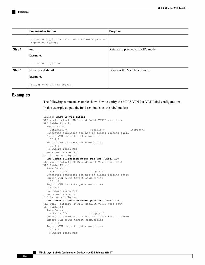
PurposeCommand or Action
Device(config)# mpls label mode all-vrfs protocolbgp-vpnv4 per-vrf
Returns to privileged EXEC mode.end
Example:
Step 4
Device(config)# end
Displays the VRF label mode.show ip vrf detail
Example:
Step 5
Device# show ip vrf detail
ExamplesThe following command example shows how to verify the MPLS VPN Per VRF Label configuration:
In this example output, the bold text indicates the label modes:
Device# show ip vrf detailVRF vpn1; default RD 1:1; default VPNID <not set>VRF Table ID = 1Interfaces:Ethernet0/0 Serial5/0 Loopback1
Connected addresses are not in global routing tableExport VPN route-target communitiesRT:1:1
Import VPN route-target communitiesRT:1:1
No import route-mapNo export route-map
CSC is not configured.VRF label allocation mode: per-vrf (Label 19)
VRF vpn2; default RD 2:1; default VPNID <not set>VRF Table ID = 2Interfaces:Ethernet2/0 Loopback2
Connected addresses are not in global routing tableExport VPN route-target communitiesRT:2:1
Import VPN route-target communitiesRT:2:1
No import route-mapNo export route-map
CSC is not configured.VRF label allocation mode: per-vrf (Label 20)
VRF vpn3; default RD 3:1; default VPNID <not set>VRF Table ID = 3Interfaces:Ethernet3/0 Loopback3
Connected addresses are not in global routing tableExport VPN route-target communitiesRT:3:1
Import VPN route-target communitiesRT:3:1
No import route-map
MPLS: Layer 3 VPNs Configuration Guide, Cisco IOS Release 15M&T196
MPLS VPN Per VRF LabelExamples

No export route-mapCSC is not configured.VRF label allocation mode: per-vrf (Label 23)
Device# show ip bgp vpnv4 all labelsNetwork Next Hop In label/Out label
Route Distinguisher: 1:1 (vpn1)127.0.0.1/32 192.168.1.1 IPv4 VRF Aggr:19/nolabel127.0.0.5/32 127.0.0.4 nolabel/19192.168.1.0/24 192.168.1.1 IPv4 VRF Aggr:19/nolabel
0.0.0.0 IPv4 VRF Aggr:19/aggregate(vpn1)192.168.4.0/24 127.0.0.4 nolabel/20172.16.0.0/16 0.0.0.0 IPv4 VRF Aggr:19/aggregate(vpn1)172.16.128.0/32 192.168.1.1 IPv4 VRF Aggr:19/nolabel
Route Distinguisher: 2:1 (vpn2)127.0.2.2/32 0.0.0.0 IPv4 VRF Aggr:20/aggregate(vpn2)127.0.0.6/32 192.168.5.1 IPv4 VRF Aggr:20/nolabel192.168.5.0/24 0.0.0.0 IPv4 VRF Aggr:20/aggregate(vpn2)172.17.128.0/32 192.168.5.1 IPv4 VRF Aggr:20/nolabel
Route Distinguisher: 3:1 (vpn3)127.0.3.2/32 0.0.0.0 IPv4 VRF Aggr:23/aggregate(vpn3)127.0.0.8/32 192.168.7.1 IPv4 VRF Aggr:23/nolabel192.168.7.0/24 0.0.0.0 IPv4 VRF Aggr:23/aggregate(vpn3)172.16.128.0/32 192.168.7.1 IPv4 VRF Aggr:23/nolabel
Device# show mpls forwarding-table
Local Outgoing Prefix Bytes tag Outgoing Next Hoptag tag or VC or Tunnel Id switched interface16 Pop tag 192.168.3.0/24 0 Et1/0 192.168.2.317 Pop tag 127.0.0.3/32 0 Et1/0 192.168.2.318 17 127.0.0.4/32 0 Et1/0 192.168.2.319 Pop Label IPv4 VRF[V] 0 aggregate/vpn120 Pop Label IPv4 VRF[V] 0 aggregate/vpn223 Pop Label IPv4 VRF[V] 0 aggregate/vpn3PE1#
Configuration Examples for MPLS VPN Per VRF Label
Example: No Label Mode Default ConfigurationThe following example shows the default label mode configuration (no label mode).
In this example output, the bold text indicates the label modes:
Device# show ip vrf detailVRF vpn1; default RD 1:1; default VPNID <not set>VRF Table ID = 1Interfaces:Ethernet0/0 Serial5/0 Loopback1
Connected addresses are not in global routing tableExport VPN route-target communitiesRT:1:1
Import VPN route-target communitiesRT:1:1
No import route-mapNo export route-map
CSC is not configured.VRF label allocation mode: per-prefixper-vrf-aggr for connected and BGP aggregates (Label 19)
MPLS: Layer 3 VPNs Configuration Guide, Cisco IOS Release 15M&T197
MPLS VPN Per VRF LabelConfiguration Examples for MPLS VPN Per VRF Label

VRF vpn2; default RD 2:1; default VPNID <not set>VRF Table ID = 2Interfaces:Ethernet2/0 Loopback2
Connected addresses are not in global routing tableExport VPN route-target communitiesRT:2:1
Import VPN route-target communitiesRT:2:1
No import route-mapNo export route-map
CSC is not configured.
VRF label allocation mode: per-prefix
per-vrf-aggr for connected and BGP aggregates (Label 20)VRF vpn3; default RD 3:1; default VPNID <not set>VRF Table ID = 3Interfaces:Ethernet3/0 Loopback3
Connected addresses are not in global routing tableExport VPN route-target communitiesRT:3:1
Import VPN route-target communitiesRT:3:1
No import route-mapNo export route-map
CSC is not configured.VRF label allocation mode: per-prefixper-vrf-aggr for connected and BGP aggregates (Label 23)
Device# show ip bgp vpnv4 all labelsNetwork Next Hop In label/Out label
Route Distinguisher: 1:1 (vpn1)127.0.0.1/32 192.168.1.1 27/nolabel127.0.0.5/32 127.0.0.4 nolabel/19192.168.1.0/24 192.168.1.1 IPv4 VRF Aggr:19/nolabel
0.0.0.0 IPv4 VRF Aggr:19/aggregate(vpn1)192.168.4.0/24 127.0.0.4 nolabel/20172.16.0.0/16 0.0.0.0 IPv4 VRF Aggr:19/aggregate(vpn1)172.16.128.0/32 192.168.1.1 28/nolabel
Route Distinguisher: 2:1 (vpn2)127.0.2.2/32 0.0.0.0 IPv4 VRF Aggr:20/aggregate(vpn2)127.0.0.6/32 192.168.5.1 21/nolabel192.168.5.0/24 0.0.0.0 IPv4 VRF Aggr:20/aggregate(vpn2)172.17.128.0/32 192.168.5.1 22/nolabel
Route Distinguisher: 3:1 (vpn3)127.0.3.2/32 0.0.0.0 IPv4 VRF Aggr:23/aggregate(vpn3)127.0.0.8/32 192.168.7.1 24/nolabel192.168.7.0/24 0.0.0.0 IPv4 VRF Aggr:23/aggregate(vpn3)172.16.128.0/32 192.168.7.1 25/nolabel
Device# show mpls forwarding-tableLocal Outgoing Prefix Bytes tag Outgoing Next Hoptag tag or VC or Tunnel Id switched interface16 Pop tag 192.168.3.0/24 0 Et1/0 192.168.2.317 Pop tag 127.0.0.3/32 0 Et1/0 192.168.2.318 17 127.0.0.4/32 0 Et1/0 192.168.2.319 Pop Label IPv4 VRF[V] 0 aggregate/vpn120 Pop Label IPv4 VRF[V] 0 aggregate/vpn221 Untagged 127.0.0.6/32[V] 0 Et2/0 192.168.5.122 Untagged 172.17.128.0/32[V]0 Et2/0 192.168.5.123 Pop Label IPv4 VRF[V] 0 aggregate/vpn324 Untagged 127.0.0.8/32[V] 0 Et3/0 192.168.7.125 Untagged 172.16.128.0/32[V]0 Et3/0 192.168.7.1
MPLS: Layer 3 VPNs Configuration Guide, Cisco IOS Release 15M&T198
MPLS VPN Per VRF LabelExample: No Label Mode Default Configuration
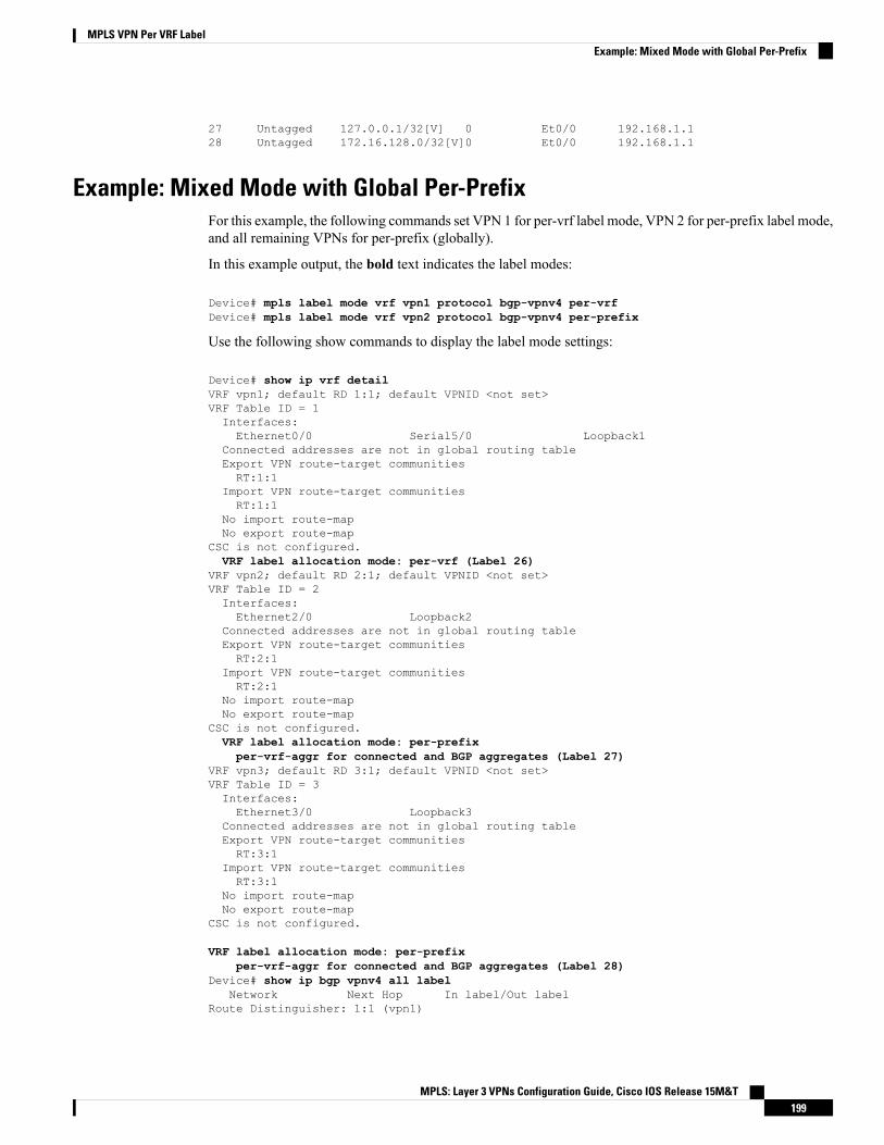
27 Untagged 127.0.0.1/32[V] 0 Et0/0 192.168.1.128 Untagged 172.16.128.0/32[V]0 Et0/0 192.168.1.1
Example: Mixed Mode with Global Per-PrefixFor this example, the following commands set VPN 1 for per-vrf label mode, VPN 2 for per-prefix label mode,and all remaining VPNs for per-prefix (globally).
In this example output, the bold text indicates the label modes:
Device# mpls label mode vrf vpn1 protocol bgp-vpnv4 per-vrfDevice# mpls label mode vrf vpn2 protocol bgp-vpnv4 per-prefix
Use the following show commands to display the label mode settings:
Device# show ip vrf detailVRF vpn1; default RD 1:1; default VPNID <not set>VRF Table ID = 1Interfaces:Ethernet0/0 Serial5/0 Loopback1
Connected addresses are not in global routing tableExport VPN route-target communitiesRT:1:1
Import VPN route-target communitiesRT:1:1
No import route-mapNo export route-map
CSC is not configured.VRF label allocation mode: per-vrf (Label 26)
VRF vpn2; default RD 2:1; default VPNID <not set>VRF Table ID = 2Interfaces:Ethernet2/0 Loopback2
Connected addresses are not in global routing tableExport VPN route-target communitiesRT:2:1
Import VPN route-target communitiesRT:2:1
No import route-mapNo export route-map
CSC is not configured.VRF label allocation mode: per-prefixper-vrf-aggr for connected and BGP aggregates (Label 27)
VRF vpn3; default RD 3:1; default VPNID <not set>VRF Table ID = 3Interfaces:Ethernet3/0 Loopback3
Connected addresses are not in global routing tableExport VPN route-target communitiesRT:3:1
Import VPN route-target communitiesRT:3:1
No import route-mapNo export route-map
CSC is not configured.
VRF label allocation mode: per-prefixper-vrf-aggr for connected and BGP aggregates (Label 28)
Device# show ip bgp vpnv4 all labelNetwork Next Hop In label/Out label
Route Distinguisher: 1:1 (vpn1)
MPLS: Layer 3 VPNs Configuration Guide, Cisco IOS Release 15M&T199
MPLS VPN Per VRF LabelExample: Mixed Mode with Global Per-Prefix

127.0.0.1/32 192.168.1.1 IPv4 VRF Aggr:26/nolabel127.0.0.5/32 127.0.0.4 nolabel/19192.168.1.0/24 0.0.0.0 IPv4 VRF Aggr:26/aggregate(vpn1)
192.168.1.1 IPv4 VRF Aggr:26/nolabel192.168.4.0/24 127.0.0.4 nolabel/20172.16.0.0/16 0.0.0.0 IPv4 VRF Aggr:26/aggregate(vpn1)172.16.128.0/32 192.168.1.1 IPv4 VRF Aggr:26/nolabel
Route Distinguisher: 2:1 (vpn2)127.0.2.2/32 0.0.0.0 IPv4 VRF Aggr:27/aggregate(vpn2)127.0.0.6/32 192.168.5.1 20/nolabel192.168.5.0/24 0.0.0.0 IPv4 VRF Aggr:27/aggregate(vpn2)172.17.128.0/32 192.168.5.1 21/nolabel
Route Distinguisher: 3:1 (vpn3)127.0.3.2/32 0.0.0.0 IPv4 VRF Aggr:28/aggregate(vpn3)127.0.0.8/32 192.168.7.1 22/nolabel192.168.7.0/24 0.0.0.0 IPv4 VRF Aggr:28/aggregate(vpn3)172.16.128.0/32 192.168.7.1 23/nolabel
Device# show mpls forwarding-table
Local Outgoing Prefix Bytes tag Outgoing Next Hoptag tag or VC or Tunnel Id switched interface16 Pop tag 192.168.3.0/24 0 Et1/0 192.168.2.317 Pop tag 127.0.0.3/32 0 Et1/0 192.168.2.318 17 127.0.0.4/32 0 Et1/0 192.168.2.320 Untagged 127.0.0.6/32[V] 0 Et2/0 192.168.5.121 Untagged 172.17.128.0/32[V]0 Et2/0 192.168.5.122 Untagged 127.0.0.8/32[V] 0 Et3/0 192.168.7.123 Untagged 172.16.128.0/32[V]0 Et3/0 192.168.7.126 Pop Label IPv4 VRF[V] 0 aggregate/vpn127 Pop Label IPv4 VRF[V] 0 aggregate/vpn128 Pop Label IPv4 VRF[V] 0 aggregate/vpn1
Example: Mixed Mode with Global Per-VRFFor this example, the following commands set VPN 1 for per-vrf label mode, VPN 2 for per-prefix label mode,and all remaining VPNs for per-vrf (globally).
In this example output, the bold text indicates the label modes:
Device# mpls label mode vrf vpn1 protocol bgp-vpnv4 per-vrfDevice# mpls label mode vrf vpn2 protocol bgp-vpnv4 per-prefixDevice# mpls label mode all-vrfs protocol bgp-vpnv4 per-vrfDevice# show ip vrf detailVRF vpn1; default RD 1:1; default VPNID <not set>VRF Table ID = 1Interfaces:Ethernet0/0 Serial5/0 Loopback1
Connected addresses are not in global routing tableExport VPN route-target communitiesRT:1:1
Import VPN route-target communitiesRT:1:1
No import route-mapNo export route-map
CSC is not configured.VRF label allocation mode: per-vrf (Label 26)
VRF vpn2; default RD 2:1; default VPNID <not set>VRF Table ID = 2Interfaces:Ethernet2/0 Loopback2
Connected addresses are not in global routing table
MPLS: Layer 3 VPNs Configuration Guide, Cisco IOS Release 15M&T200
MPLS VPN Per VRF LabelExample: Mixed Mode with Global Per-VRF
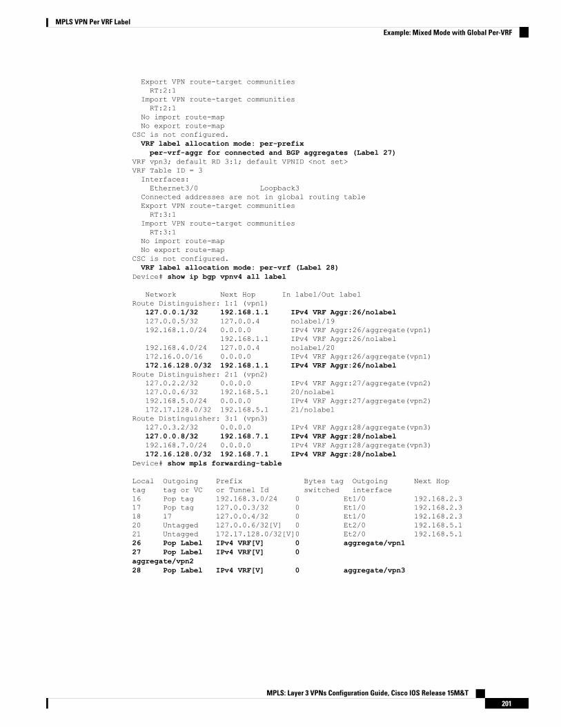
Export VPN route-target communitiesRT:2:1
Import VPN route-target communitiesRT:2:1
No import route-mapNo export route-map
CSC is not configured.VRF label allocation mode: per-prefixper-vrf-aggr for connected and BGP aggregates (Label 27)
VRF vpn3; default RD 3:1; default VPNID <not set>VRF Table ID = 3Interfaces:Ethernet3/0 Loopback3
Connected addresses are not in global routing tableExport VPN route-target communitiesRT:3:1
Import VPN route-target communitiesRT:3:1
No import route-mapNo export route-map
CSC is not configured.VRF label allocation mode: per-vrf (Label 28)
Device# show ip bgp vpnv4 all label
Network Next Hop In label/Out labelRoute Distinguisher: 1:1 (vpn1)
127.0.0.1/32 192.168.1.1 IPv4 VRF Aggr:26/nolabel127.0.0.5/32 127.0.0.4 nolabel/19192.168.1.0/24 0.0.0.0 IPv4 VRF Aggr:26/aggregate(vpn1)
192.168.1.1 IPv4 VRF Aggr:26/nolabel192.168.4.0/24 127.0.0.4 nolabel/20172.16.0.0/16 0.0.0.0 IPv4 VRF Aggr:26/aggregate(vpn1)172.16.128.0/32 192.168.1.1 IPv4 VRF Aggr:26/nolabel
Route Distinguisher: 2:1 (vpn2)127.0.2.2/32 0.0.0.0 IPv4 VRF Aggr:27/aggregate(vpn2)127.0.0.6/32 192.168.5.1 20/nolabel192.168.5.0/24 0.0.0.0 IPv4 VRF Aggr:27/aggregate(vpn2)172.17.128.0/32 192.168.5.1 21/nolabel
Route Distinguisher: 3:1 (vpn3)127.0.3.2/32 0.0.0.0 IPv4 VRF Aggr:28/aggregate(vpn3)127.0.0.8/32 192.168.7.1 IPv4 VRF Aggr:28/nolabel192.168.7.0/24 0.0.0.0 IPv4 VRF Aggr:28/aggregate(vpn3)172.16.128.0/32 192.168.7.1 IPv4 VRF Aggr:28/nolabel
Device# show mpls forwarding-table
Local Outgoing Prefix Bytes tag Outgoing Next Hoptag tag or VC or Tunnel Id switched interface16 Pop tag 192.168.3.0/24 0 Et1/0 192.168.2.317 Pop tag 127.0.0.3/32 0 Et1/0 192.168.2.318 17 127.0.0.4/32 0 Et1/0 192.168.2.320 Untagged 127.0.0.6/32[V] 0 Et2/0 192.168.5.121 Untagged 172.17.128.0/32[V]0 Et2/0 192.168.5.126 Pop Label IPv4 VRF[V] 0 aggregate/vpn127 Pop Label IPv4 VRF[V] 0aggregate/vpn228 Pop Label IPv4 VRF[V] 0 aggregate/vpn3
MPLS: Layer 3 VPNs Configuration Guide, Cisco IOS Release 15M&T201
MPLS VPN Per VRF LabelExample: Mixed Mode with Global Per-VRF
Additional ReferencesRelated Documents
Document TitleRelated Topic
Cisco Master Command List, All ReleasesCisco IOS commands
Cisco IOSMultiprotocol Label Switching Command ReferenceMPLS and MPLS applications commands
MPLS Layer 3 VPNs Configuration GuideMPLS VPNs
Standards and RFCs
TitleStandard/RFC
BGP/MPLSRFC 2547
Technical Assistance
LinkDescription
http://www.cisco.com/cisco/web/support/index.htmlTheCisco Support andDocumentationwebsite providesonline resources to download documentation, software,and tools. Use these resources to install and configurethe software and to troubleshoot and resolve technicalissues with Cisco products and technologies. Access tomost tools on the Cisco Support and Documentationwebsite requires a Cisco.com user ID and password.
Feature Information for MPLS VPN Per VRF LabelThe following table provides release information about the feature or features described in this module. Thistable lists only the software release that introduced support for a given feature in a given software releasetrain. Unless noted otherwise, subsequent releases of that software release train also support that feature.
Use Cisco Feature Navigator to find information about platform support and Cisco software image support.To access Cisco Feature Navigator, go to www.cisco.com/go/cfn. An account on Cisco.com is not required.
MPLS: Layer 3 VPNs Configuration Guide, Cisco IOS Release 15M&T202
MPLS VPN Per VRF LabelAdditional References

Table 13: Feature Information for MPLS VPN Per VRF Label
Feature InformationReleasesFeature Name
TheMPLSVPN Per VRF Label feature allows a user to configurea single VPN label for all local routes in the entire VPN routingand forwarding (VRF) domain. The feature incorporates a single(per VRF) VPN label for all local routes in the VRF table.
In Cisco IOS Release 12.2(18)SXF2, this feature was introduced.
In Cisco IOS Releases 12.2(33)SRA, 12.2(33)SRD, and 12.4(6)T,this feature was integrated.
In Cisco IOS XE Release 2.2, support was added for the CiscoASR 1000 Series Routers.
The following commands were introduced or modified:
debug ip bgp vpnv4 unicast, mpls label mode.
12.2(18)SXF2
12.2(33)SRA
12.2(33)SXH
12.4(6)T
Cisco IOS XE Release2.2
MPLS VPN PerVRF Label
MPLS: Layer 3 VPNs Configuration Guide, Cisco IOS Release 15M&T203
MPLS VPN Per VRF LabelFeature Information for MPLS VPN Per VRF Label

MPLS: Layer 3 VPNs Configuration Guide, Cisco IOS Release 15M&T204
MPLS VPN Per VRF LabelFeature Information for MPLS VPN Per VRF Label
C H A P T E R 13MPLS VPN SNMP Notifications
This document describes the Simple Network Management Protocol (SNMP) agent support in Cisco IOS forMultiprotocol Label Switching (MPLS) Virtual Private Network (VPN) event notifications as implementedin the notifications section of the draftMPLS/BGP Virtual Private Network Management Information BaseUsing SMIv2 (draft-ietf-ppvpn-mpls-vpn-mib-03.txt).
The MPLS VPN technology allows service providers to offer intranet and extranet VPN services that directlyconnect their customers' remote offices to a public network with the same security and service levels that aprivate network offers. The Provider-Provisioned VPN (PPVPN)-MPLS-VPN MIB notifications provideSNMP notification for critical MPLS VPN events.
The MPLS VPN SNMP Notifications feature provides the following benefits:
• A standards-based SNMP interface for retrieving information about critical MPLS VPN events.
• The generation and queuing of notifications that call attention to major changes in the operational statusof MPLS VPN enabled interfaces; the forwarding of notification messages to a designated NMS forevaluation and action by network administrators.
• Advanced warning when VPN routing tables are approaching or exceed their capacity.
• Warnings about the reception of illegal labels on a VRF enabled interface. Such receptions may indicatemisconfiguration or an attempt to violate security.
• Finding Feature Information, on page 205• Prerequisites for MPLS VPN SNMP Notifications , on page 206• Restrictions for MPLS VPN SNMP Notifications , on page 206• Information About MPLS VPN SNMP Notifications, on page 206• How to Configure the MPLS VPN SNMP Notifications, on page 209• Configuration Examples for MPLS VPN SNMP Notifications, on page 214• Additional References, on page 215• Feature Information for MPLS VPN SNMP Notifications, on page 216• Glossary, on page 217
Finding Feature InformationYour software release may not support all the features documented in this module. For the latest caveats andfeature information, see Bug Search Tool and the release notes for your platform and software release. To
MPLS: Layer 3 VPNs Configuration Guide, Cisco IOS Release 15M&T205
find information about the features documented in this module, and to see a list of the releases in which eachfeature is supported, see the feature information table.
Use Cisco Feature Navigator to find information about platform support and Cisco software image support.To access Cisco Feature Navigator, go to www.cisco.com/go/cfn. An account on Cisco.com is not required.
Prerequisites for MPLS VPN SNMP NotificationsThe MPLS VPN SNMP Notifications feature requires the following:
• SNMP is installed and enabled on the label switching routers.
• Multiprotocol Label Switching (MPLS) is enabled on the label switching routers.
• Multiprotocol Border Gateway Protocol (BGP) is enabled on the label switching routers.
• Cisco Express Forwarding is enabled on the label switching routers.
Restrictions for MPLS VPN SNMP Notifications• The MPLS-VPN-MIB agent is not implemented in this release.
• Configuration of the MIB using the SNMP SET command is not supported in this release.
• The retrieval of MPLS-VPN-MIB objects using SNMP GET is not supported in this release.
Information About MPLS VPN SNMP Notifications
Cisco Implementation of MPLS VPN MIBSNMP agent code operating with the notifications of the MPLS VPN SNMP Notifications feature enables astandardized, SNMP-based approach to monitoring the MPLS VPN MIB notifications that aid in themanagement of Multiprotocol Label Switching (MPLS) Virtual Private Networks (VPNs) in Cisco software.
The MPLS VPN SNMP Notifications feature is based on the IETF draft specificationdraft-ietf-ppvpn-mpls-vpn-mib-02.txt, which includes notification objects that support MPLSVPN notificationevents. This IETF draft MIB, which undergoes revisions from time to time, is being evolved toward becominga standard. Accordingly, the Cisco implementation of features of the MPLS VPN MIB is expected to trackthe evolution of the IETF draft MIB, and may change accordingly.
Some slight differences between the IETF draft MIB and the actual implementation of MPLS VPNs withinCisco software require some minor translations between the MPLS VPNMIB and the internal data structuresof Cisco software. These translations are accomplished bymeans of the SNMP agent code. Also, while runningas a low priority process, the SNMP agent provides a management interface to Cisco software. SNMP addslittle overhead on the normal functions of the device.
The SNMP objects defined in theMPLSVPNMIB notifications can be viewed by any standard SNMP utility.The network administrator can retrieve information in the MPLS VPN MIB using standard SNMP get andgetnext operations for SNMP v1, v2, and v3.
MPLS: Layer 3 VPNs Configuration Guide, Cisco IOS Release 15M&T206
MPLS VPN SNMP NotificationsPrerequisites for MPLS VPN SNMP Notifications
All MPLS VPN MIB objects are based on the IETF draft MIB; thus, no specific Cisco SNMP application isrequired to support the functions and operations pertaining to the MPLS VPN SNMP Notifications feature.
This section contains the following information about the Cisco implementation of the MPLS VPN MIB:
Capabilities Supported by MPLS VPN SNMP NotificationsThe following functionality is supported in this release for the MPLS VPN SNMP Notifications feature. Thisfeature provides you with the ability to do the following:
• Create and send notification messages that signal changes when critical Multiprotocol Label Switching(MPLS) Virtual Private Network (VPN) events occur.
• Enable, disable, and configure notification messages for MPLS VPN events by using extensions toexisting SNMP CLI commands.
• Specify the IP address of a network management system (NMS) in the operating environment to whichnotification messages are sent.
• Write notification configurations into nonvolatile memory.
Notification Generation Events for the MPLS VPN MIBThe following notifications of the MPLS VPN MIB are implemented for this release:
• mplsVrfIfUp—Sent to an NMS when an interface comes up and is assigned a VPN routing/forwardingtable instance (VRF).
• mplsVrfIfDown—Generated and sent to the NMS when a VRF is removed from an interface or theinterface transitions from an operationally “up” state to a “down” state.
For the mplsVrfIfUp or mplsVrfIfDown notifications to be issued on ATM or Frame Relay subinterfaces,you must configure the snmp-server traps atm subif command or the snmp-server traps frame-relay subifcommand on the subinterfaces, respectively.
Note
• mplsNumVrfRouteMidThreshExceeded—Generated and sent when the middle (warning) thresholdis crossed. You can configure this threshold in the CLI by using the following commands:
Router(config)# ip vrf vrf-nameRouter(config-vrf)# maximum routes max-threshmid-thresh (% of max)
This notification is sent to the NMS only at the time the threshold is exceeded.Whenever the number of routesfalls below this threshold and exceeds the threshold again, a notification is sent to the NMS. (See the figurebelow for a comparison of the warning and maximum thresholds.)
• mplsNumVrfRouteMaxThreshExceeded—Generated and sent when you attempt to create a route ona VRF that already contains the maximum number of routes as defined by the following CLI commands:
Router(config)# ip vrf vrf-nameRouter(config-vrf)# maximum routes max-threshmid-thresh (% of max)
MPLS: Layer 3 VPNs Configuration Guide, Cisco IOS Release 15M&T207
MPLS VPN SNMP NotificationsCapabilities Supported by MPLS VPN SNMP Notifications

A trap notification is sent to the NMSwhen you attempt to exceed themaximum threshold. Another notificationis not sent until the number of routes falls below the maximum threshold and reaches the maximum thresholdagain. (See the figure below for an example of how this notification works and for a comparison of themaximum and warning thresholds.)
Themaximum routes command sets the number of routes for a VRF. You cannot exceed the number ofroutes in the VRF that you set with themaximum routes max-thresh CLI command. Prior to thisimplementation of theMPLS-VPN-MIB, you were not notified when this threshold (or the warning threshold)was reached.
Note
• mplsNumVrfSecIllegalLabelThreshExceeded—Generated and sent when the amount of illegal labelsreceived on a VRF interface exceeds the thresholdmplsVpnVrfSecIllegalLabelRcvThresh. This thresholdis defined with a value of 0. Therefore, a notification is sent when the first illegal label is received on aVRF. Labels are considered illegal if they are outside of the valid label range, do not have a LabelForwarding Information Base (LFIB) entry, or the table ID of the message does not match the table IDfor the label in the LFIB.
Figure 14: Comparison of Warning and Maximum Thresholds
Notification Specification for MPLS-VPN-MIBIn an SNMPv1 notification, each VPN notification has a generic type identifier and an enterprise-specifictype identifier for identifying the notification type.
• The generic type for all VPN notifications is “enterpriseSpecific” as this is not one of the genericnotification types defined for SNMP.
MPLS: Layer 3 VPNs Configuration Guide, Cisco IOS Release 15M&T208
MPLS VPN SNMP NotificationsNotification Specification for MPLS-VPN-MIB

• The enterprise-specific type is identified as follows:
• 1 for mplsVrfIfUp• 2 for mplsVrfIfDown• 3 for mplsNumVrfRouteMidThreshExceeded• 4 for mplsNumVrfRouteMaxThreshExceeded• 5 for mplsNumVrfSecIllegalLabelThreshExceeded
In SNMPv2, the notification type is identified by an SnmpTrapOID varbind (variable binding consisting ofan object identifier (OID) type and value) included within the notification message.
Each notification also contains two additional objects from the MPLS-VPN-MIB. These objects provideadditional information about the event, as follows:
• The VRF interface up/down notifications provide additional variables--mplsVpnInterfaceConfIndex andmplsVpnVrfName-- in the notification. These variables describe the SNMP interface index and the VRFname, respectively.
• The mid and max threshold notifications include the mplsVpnVrfName variable (VRF name) as well asthemplsVpnVrfPerfCurrNumRoutes variable that indicates the current number of routes within the VRF.
• The illegal label notification includes the mplsVpnVrfName variable (VRF name) and themplsVpnVrfSecIllegalLabelViolations variable that maintains the current count of illegal labels on aVPN.
Monitoring the MPLS VPN SNMP NotificationsWhen MPLS-VPN-MIB notifications are enabled, notification messages relating to specific MultiprotocolLabel Switching (MPLS) Virtual Private Network (VPN) events within Cisco software are generated and sentto a specified network management system (NMS) in the network. Any utility that supports SNMPv1 orSNMPv2 notifications can receive notification messages.
To monitor MPLS-VPN-MIB notification messages, log in to an NMS that supports a utility that displaysSNMP notifications, and start the display utility.
How to Configure the MPLS VPN SNMP Notifications
Configuring an SNMP CommunityAnSNMP community string defines the relationship between the SNMPmanager and the agent. The communitystring acts like a password to regulate access to the agent on the device.
Perform this task to configure an SNMP community.
SUMMARY STEPS
1. enable2. show running-config3. configure terminal4. snmp-server community string [view view-name] [ro | rw] [acl-number]
MPLS: Layer 3 VPNs Configuration Guide, Cisco IOS Release 15M&T209
MPLS VPN SNMP NotificationsMonitoring the MPLS VPN SNMP Notifications

5. do copy running-config startup-config
DETAILED STEPS
PurposeCommand or Action
Enables privileged EXEC mode.enableStep 1
Example: • Enter your password if prompted.
Device> enable
Displays the running configuration to determine if an SNMPagent is already running.
show running-config
Example:
Step 2
If no SNMP information is displayed, continue with thenext step. If any SNMP information is displayed, you canmodify the information or change it as needed.
Device# show running-config
Enters global configuration mode.configure terminal
Example:
Step 3
Device# configure terminal
Sets up the community access string to permit access to theSimple Network Management Protocol (SNMP).
snmp-server community string [view view-name] [ro |rw] [acl-number]
Step 4
Example: • The string argument acts like a password and permitsaccess to the SNMP protocol.
Device(config)# snmp-server community comaccess ro• The viewview-name keyword and argument specifiesthe name of a previously defined view. The viewdefines the objects available to the community.
• The ro keyword specifies read-only access. Authorizedmanagement stations are only able to retrieve MIBobjects.
• The rw keyword specifies read-write access.Authorized management stations are able to bothretrieve and modify MIB objects.
• The acl-number argument is an integer from 1 to 99that specifies an access list of IP addresses that areallowed to use the community string to gain access tothe SNMP agent.
Saves the modified configuration to nonvolatile memory(NVRAM) as the startup configuration file. (The do
do copy running-config startup-config
Example:
Step 5
command allows you to perform Exec level commands inconfiguration mode.)
Device(config)# do copy running-configstartup-config
MPLS: Layer 3 VPNs Configuration Guide, Cisco IOS Release 15M&T210
MPLS VPN SNMP NotificationsConfiguring an SNMP Community

Configuring the Device to Send SNMP TrapsPerform this task to configure the device to send traps to a host.
The snmp-server host command specifies which hosts receive traps. The snmp-server enable traps commandglobally enables the trap production mechanism for the specified traps.
Although you can set the community-string argument using the snmp-server host command by itself, werecommend you define this string using the snmp-server community command prior to using the snmp-serverhost command.
Note
SUMMARY STEPS
1. enable2. configure terminal3. snmp-server host host-addr [traps | informs] [version {1 | 2c | 3 [auth | noauth | priv]}] community-string
[udp-port port] [notification-type]4. Do one of the following:
• snmp-server enable traps atm [pvc | subif]• snmp-server enable traps frame-relay [subif]
5. snmp-server enable traps mpls vpn6. end
DETAILED STEPS
PurposeCommand or Action
Enables privileged EXEC mode.enableStep 1
Example: • Enter your password if prompted.
Device> enable
Enters global configuration mode.configure terminal
Example:
Step 2
Device# configure terminal
Specifies the recipient of an SNMP notification operation.snmp-server host host-addr [traps | informs] [version {1| 2c | 3 [auth | noauth | priv]}] community-string [udp-portport] [notification-type]
Step 3
• The host-addr argument specifies the name or Internetaddress of the host (the targeted recipient).
Example:• The traps keyword sends SNMP traps to this host.This is the default.Device(config)# snmp-server host 172.20.2.160 traps
comaccess mpls-vpn • The informs keyword sends SNMP informs to thishost.
MPLS: Layer 3 VPNs Configuration Guide, Cisco IOS Release 15M&T211
MPLS VPN SNMP NotificationsConfiguring the Device to Send SNMP Traps

PurposeCommand or Action
• The version keyword specifies the version of theSNMP used to send the traps. Version 3 is the mostsecure model, as it allows packet encryption with thepriv keyword. If you use the version keyword, youmust specify one of the following:
• 1—SNMPv1. This option is not available withinforms.
• 2c—SNMPv2C.• 3—SNMPv3. The following three optionalkeywords can follow the version 3 keyword(auth, noauth, priv).
• The community-string argument is a password-likecommunity string sent with the notification operation.
• The udp-port port keyword and argument names theUDP port of the host to use. The default is 162.
• The notification-type argument specifies the type ofnotification to be sent to the host. If no type isspecified, all notifications are sent. MPLS VPNnotifications are specified with thempls-vpn keyword.
(For ATM subinterfaces only) Enables the sending of ATMSNMP notifications.
Do one of the following:Step 4
• snmp-server enable traps atm [pvc | subif]• The pvc keyword enables SNMP ATM permanentvirtual circuit (PVC) traps.
• snmp-server enable traps frame-relay [subif]
Example:• The subif keyword enables SNMP ATM subinterfacetraps.Device(config)# snmp-server enable traps atm subif
Example:or
Device(config)# snmp-server enable trapsframe-relay subif
(For Frame Relay subinterfaces only) Enables Frame RelayDLCI link status SNMP notifications.
• The subif keyword enables SNMP Frame Relaysubinterface traps.
FormplsVrfIfUp ormplsVrfIfDown notificationsto be issued on ATM or Frame Relaysubinterfaces, youmust configure the appropriatesnmp-server enable traps command with thesubif keyword.
Note
Enables the device to sendMPLSVPNSNMP notifications.snmp-server enable traps mpls vpn
Example:
Step 5
Device(config)# snmp-server enable traps mpls vpnvrf-up vrf-down
MPLS: Layer 3 VPNs Configuration Guide, Cisco IOS Release 15M&T212
MPLS VPN SNMP NotificationsConfiguring the Device to Send SNMP Traps

PurposeCommand or Action
(Optional) Returns to user EXEC mode.end
Example:
Step 6
Device(config)# end
Configuring Threshold Values for MPLS VPN SNMP NotificationsPerform this task to configure threshold values for MPLS VPN SNMP notifications.
The mplsNumVrfRouteMidThreshExceeded notification event is generated and sent when the middle(warning) threshold is crossed. You can configure this threshold in the CLI by using themaximum routescommand in VRF configuration mode. This notification is sent to the NMS only at the time the threshold isexceeded. Whenever the number of routes falls below this threshold and exceeds the threshold again, anotification is sent to the NMS.
ThemplsNumVrfRouteMaxThreshExceeded notification event is generated and sent when you attempt tocreate a route on a VRF that already contains the maximum number of routes as defined by themaximumroutes command in VRF configuration mode. A trap notification is sent to the NMS when you attempt toexceed the maximum threshold. Another notification is not sent until the number of routes falls below themaximum threshold and reaches the maximum threshold again.
(See the figure above for an example of how this notification works and for a comparison of the maximumand warning thresholds.)
Themaximum routes command sets the number of routes for a VRF. You cannot exceed the number ofroutes in the VRF that you set with themaximum routes max-thresh CLI command. Prior to thisimplementation of theMPLS-VPN-MIB, you were not notified when this threshold (or the warning threshold)was reached.
Note
SUMMARY STEPS
1. enable2. configure terminal3. ip vrf vrf-name4. maximum routes limit {warn-threshold | warning-only}5. end
DETAILED STEPS
PurposeCommand or Action
Enables privileged EXEC mode.enableStep 1
Example: • Enter your password if prompted.
Device> enable
MPLS: Layer 3 VPNs Configuration Guide, Cisco IOS Release 15M&T213
MPLS VPN SNMP NotificationsConfiguring Threshold Values for MPLS VPN SNMP Notifications

PurposeCommand or Action
Enters global configuration mode.configure terminal
Example:
Step 2
Device# configure terminal
Configures a VRF routing table.ip vrf vrf-nameStep 3
Example: • The vrf-name argument specifies the name assignedto a VRF.
Device(config)# ip vrf vpn1
Limits the maximum number of routes in a VRF to preventa PE device from importing too many routes.
maximum routes limit {warn-threshold | warning-only}
Example:
Step 4
• The limit argument specifies the maximum number ofroutes allowed in a VRF. You may select from 1 to4,294,967,295 routes to be allowed in a VRF.
Device(config-vrf)# maximum routes 10000 80
• The warn-threshold argument specifies when thethreshold limit is reached and routes are rejected. Thethreshold limit is a percentage of the limit specified,from 1 to 100 percent.
• Thewarning-only keyword specifies that a SYSLOGerror message is issued when the maximum numberof routes allowed for a VRF exceeds the threshold.However, additional routes are still allowed.
(Optional) Returns to privileged EXEC mode.end
Example:
Step 5
Device(config-vrf)# end
Configuration Examples for MPLS VPN SNMP Notifications
Example: Configuring the CommunityThe following example shows enabling a simple SNMP community group. This configuration permits anySNMP client to access all MPLS-VPN-MIB objects with read-only access using the community stringcomaccess.
Device# configure terminalDevice(config)# snmp-server community comaccess ro
Verify that the SNMP master agent is enabled for the MPLS VPN SNMP Notifications feature:
Device# show running-config | include snmp-serverBuilding configuration...
MPLS: Layer 3 VPNs Configuration Guide, Cisco IOS Release 15M&T214
MPLS VPN SNMP NotificationsConfiguration Examples for MPLS VPN SNMP Notifications

....snmp-server community comaccess RO....
If you do not see any “snmp-server” statements, SNMP has not been enabled on the device.Note
Example: Configuring the Device to Send SNMP TrapsThe following example shows you how to enable the device to send MPLS VPN notifications to host172.20.2.160 using the comaccess community string if a VRF transitions from a down state to an up state orfrom an up state to a down state.
Device# configure terminalDevice(config)# snmp-server host 172.20.2.160 traps comaccess mpls-vpnDevice(config)# snmp-server enable traps mpls vpn vrf-up vrf-down
Example: Configuring Threshold Values for MPLS VPN SNMP NotificationsThe following example shows how to set a maximum threshold or 10000 routes and a warning threshold thatis 80 percent of the maximum threshold for a VRF named vpn1 on a device:
Device(config)# ip vrf vpn1Device(config)# maximum routes 10000 80
Additional ReferencesRelated Documents
Document TitleRelated Topic
Cisco IOS Master Command List, All ReleasesCisco IOS commands
Cisco IOSMultiprotocol Label SwitchingCommandReferenceMPLS commands
“MPLSVirtual Private Networks” module in theMPLS Layer3 VPNs Configuration Guide
MPLS Virtual Private Network (VPN)configuration tasks
MIBs
MIBs LinkMIBs
To obtain lists of supported MIBs by platform and Cisco softwarerelease, and to download MIB modules, go to the Cisco MIBwebsite on Cisco.com at the following URL:
http://www.cisco.com/public/sw-center/netmgmt/cmtk/mibs.shtml
MPLS/BGP Virtual Private NetworkManagement Information Base UsingSMIv2(draft-ietf-ppvpn-mpls-vpn-mib-03.txt )
MPLS-VPN-MIB.my
MPLS: Layer 3 VPNs Configuration Guide, Cisco IOS Release 15M&T215
MPLS VPN SNMP NotificationsExample: Configuring the Device to Send SNMP Traps

RFCs
TitleRFCs
The Interfaces Group MIB using SMIv2RFC2233
Technical Assistance
LinkDescription
http://www.cisco.com/cisco/web/support/index.htmlTheCisco Support andDocumentationwebsite providesonline resources to download documentation, software,and tools. Use these resources to install and configurethe software and to troubleshoot and resolve technicalissues with Cisco products and technologies. Access tomost tools on the Cisco Support and Documentationwebsite requires a Cisco.com user ID and password.
Feature Information for MPLS VPN SNMP NotificationsThe following table provides release information about the feature or features described in this module. Thistable lists only the software release that introduced support for a given feature in a given software releasetrain. Unless noted otherwise, subsequent releases of that software release train also support that feature.
Use Cisco Feature Navigator to find information about platform support and Cisco software image support.To access Cisco Feature Navigator, go to www.cisco.com/go/cfn. An account on Cisco.com is not required.
MPLS: Layer 3 VPNs Configuration Guide, Cisco IOS Release 15M&T216
MPLS VPN SNMP NotificationsFeature Information for MPLS VPN SNMP Notifications

Table 14: Feature Information for MPLS VPN SNMP Notifications
Feature InformationReleasesFeature Name
The MPLS VPN SNMPNotifications feature providesSimple Network ManagementProtocol (SNMP) agent support inCisco software for MultiprotocolLabel Switching (MPLS) VirtualPrivate Network (VPN) eventnotifications.
In Cisco IOS Release 12.0(21)ST,this feature was introduced.
In Cisco IOS Release 12.0(22)S,this feature was integrated.
In Cisco IOS Release 12.2(13)T,this feature was integrated.
Supported platforms:
• Cisco IOS 12.0 S and STReleases: Cisco 7500 series,Cisco 12000 series.
• Cisco IOS 12.2 T Releases:Cisco 3620, Cisco 3640, Cisco7200 series, Cisco 7500 series,Cisco MGX 8850-RPM.
In Cisco IOS Releases12.0(21)ST and12.0(22)S, the PPVPNMPLS-VPN-MIBnotifications aredescribed in theMPLSVPN--SNMP MIBSupport feature module.
Note
The following commands wereintroduced or modified:snmp-server enable traps mplsvpn, snmp-server host.
12.0(21)ST
12.0(22)S
12.2(13)T
MPLS VPN SNMP Notifications
GlossaryASN.1—Abstract Syntax Notation One. OSI language for describing data types independent of particularcomputer structures and representation techniques. Described by ISO International Standard 8824.
MPLS: Layer 3 VPNs Configuration Guide, Cisco IOS Release 15M&T217
MPLS VPN SNMP NotificationsGlossary

BGP—Border Gateway Protocol. The exterior Border Gateway Protocol used to exchange routing informationbetween routers in separate autonomous systems. BGP uses Transmission Control Protocol (TCP). BecauseTCP is a reliable protocol, BGP does not experience problems with dropped or fragmented data packets.
CEF—Cisco Express Forwarding. An advanced Layer 3 IP switching technology. CEF optimizes networkperformance and scalability for networks with large and dynamic traffic patterns.
CE device—customer edge router. A router on the border between a VPN provider and a VPN customer thatbelongs to the customer.
community—In SNMP, a logical group of managed devices and NMSs in the same administrative domain.
community name—See community string.
community string—Text string that acts as a password and is used to authenticate messages sent between amanaged station and a router containing an SNMP agent. The community string is sent in every packet betweenthe manager and the client. Also called a community name.
IETF—Internet Engineering Task Force. Task force consisting of over 80 working groups responsible fordeveloping Internet standards. The IETF operates under the auspices of ISOC. See also ISOC.
informs—A type of notification message that is more reliable than a conventional trap notification message,because the informs message notification requires acknowledgment, and a trap notification does not.
ISOC—Internet Society. International nonprofit organization, founded in 1992, that coordinates the evolutionand use of the Internet. In addition, ISOC delegates authority to other groups related to the Internet, such asthe IAB. ISOC is headquartered in Reston, Virginia (United States).
label—A short, fixed-length data construct that tells switching nodes how to forward data (packets or cells).
label distribution protocol—See LDP.
label forwarding information base—See LFIB.
label switch router—See LSR.
LDP—label distribution protocol. A standard protocol between MPLS-enabled routers that is used for thenegotiation of the labels (addresses) used to forward packets.
LFIB—label forwarding information base. In the Cisco Label Switching system, the data structure for storinginformation about incoming and outgoing tags (labels) and associated equivalent packets suitable for labeling.
LSR—label switch router. A device that forwards MPLS packets based on the value of a fixed-length labelencapsulated in each packet.
MIB—Management Information Base. Database of network management information that is used andmaintained by a network management protocol such as SNMP or CMIP. The value of a MIB object can bechanged or retrieved using SNMP or CMIP commands, usually through a GUI network management system.MIB objects are organized in a tree structure that includes public (standard) and private (proprietary) branches.
MPLS—Multiprotocol Label Switching. A method for forwarding packets (frames) through a network. Itenables routers at the edge of a network to apply labels to packets (frames). ATM switches or existing routersin the network core can switch packets according to the labels with minimal lookup overhead.
MPLS interface—An interface on which MPLS traffic is enabled.
MPLSVPN—Multiprotocol Label Switching Virtual Private Network. UsingMPLSVPNs in a Cisco networkprovide the capability to deploy and administer scalable Layer 3 VPN backbone services including applications,data hosting network commerce, and telephony services, to business customers. A VPN is a secure IP-basednetwork that shares resources on one or more physical networks. A VPN contains geographically dispersedsites that can communicate securely over a shared backbone.
MPLS: Layer 3 VPNs Configuration Guide, Cisco IOS Release 15M&T218
MPLS VPN SNMP NotificationsGlossary

For an MPLS VPN Solution, an MPLS VPN is a set of PEs that are connected by means of a common“backbone” network to supply private IP interconnectivity between two or more customer sites for a givencustomer. Each VPN has a set of provisioning templates and policies and can span multiple provideradministrative domains (PADs).
Multiprotocol label Switching—SeeMPLS.
notification—A message sent by an SNMP agent to a network management station, console, or terminal toindicate that a significant event within Cisco software has occurred. See also trap.
NMS—network management system. A powerful, well-equipped computer (typically an engineeringworkstation) that is used by a network administrator to communicate with other devices in the network. AnNMS is typically used to manage network resources, gather statistics, and perform a variety of networkadministration and configuration tasks.
PE device—provider edge router. A router on the border between a VPN provider and a VPN customer thatbelongs to the provider.
PPVPN—Provider-Provisioned VPN. The name of the IETF working group that is developing thePPVPN-MPLS-VPN MIB (MPLS-VPN-MIB).
QoS—quality of service. Measure of performance for a transmission system that reflects its transmissionquality and service availability.
RSVP—Resource Reservation Protocol. Protocol for reserving network resources to provide Quality ofService guarantees to application flows.
Simple Network Management Protocol—See SNMP.
SNMP—Simple Network Management Protocol. Network management protocol used almost exclusively inTCP/IP networks. SNMP provides a means to monitor and control network devices, and to manageconfigurations, statistics collection, performance, and security. See also SNMP2.
SNMP2—SNMP Version 2. Version 2 of the popular network management protocol. SNMP2 supportscentralized as well as distributed network management strategies, and includes improvements in the SMI,protocol operations, management architecture, and security. See also SNMP.
traffic engineering—The techniques and processes used to cause routed traffic to travel through the networkon a path other than the one that would have been chosen if standard routing methods had been used.
trap—Amessage sent by an SNMP agent to a network management station, console, or terminal, indicatingthat a significant event occurred. Traps (notifications) are less reliable than inform requests, because thereceiver does not send an acknowledgment when it receives a trap. The sender cannot determine if the trapwas received. See also notification.
VPN—Virtual Private Network. A group of sites that, as the result of a set of administrative policies, areable to communicate with each other over a shared backbone network. SeeMPLS VPN.
VRF—VPN routing/forwarding instance. A VRF consists of an IP routing table, a derived forwarding table,a set of interfaces that use the forwarding table, and a set of rules and routing protocols that determine whatgoes into the forwarding table. In general, a VRF includes the routing information that defines a customerVPN site that is attached to a PE device.
MPLS: Layer 3 VPNs Configuration Guide, Cisco IOS Release 15M&T219
MPLS VPN SNMP NotificationsGlossary

MPLS: Layer 3 VPNs Configuration Guide, Cisco IOS Release 15M&T220
MPLS VPN SNMP NotificationsGlossary
C H A P T E R 14Multi-VRF Selection Using Policy-Based Routing
TheMulti-VRF Selection Using Policy-Based Routing (PBR) feature allows a specified interface on a provideredge (PE) device to route packets to Virtual Private Networks (VPNs) based on packet length or match criteriadefined in an IP access list.
You can enable VPN routing and forwarding (VRF) selection by policy routing packets through a route map,through the global routing table, or to a specified VRF.
You can enable policy-routing packets for VRF instances by using route map commands with set commands.
On supported hardware, you can configure both theMulti-VRF Selection Using Policy-Based Routing featureand the MPLS VPN VRF Selection Based on a Source IP Address feature on the same interface.
• Finding Feature Information, on page 221• Prerequisites for Multi-VRF Selection Using Policy-Based Routing, on page 222• Restrictions for Multi-VRF Selection Using Policy-Based Routing, on page 222• Information About Multi-VRF Selection Using Policy-Based Routing, on page 223• How to Configure Multi-VRF Selection Using Policy-Based Routing, on page 226• Configuration Examples for Multi-VRF Selection Using Policy-Based Routing, on page 234• Additional References, on page 235• Feature Information for Multi-VRF Selection Using Policy-Based Routing, on page 235• Glossary, on page 236
Finding Feature InformationYour software release may not support all the features documented in this module. For the latest caveats andfeature information, see Bug Search Tool and the release notes for your platform and software release. Tofind information about the features documented in this module, and to see a list of the releases in which eachfeature is supported, see the feature information table.
Use Cisco Feature Navigator to find information about platform support and Cisco software image support.To access Cisco Feature Navigator, go to www.cisco.com/go/cfn. An account on Cisco.com is not required.
MPLS: Layer 3 VPNs Configuration Guide, Cisco IOS Release 15M&T221
Prerequisites for Multi-VRF Selection Using Policy-BasedRouting
• The device must support policy-based routing (PBR) in order for you to configure this feature. Forplatforms that do not support PBR, use the MPLS VPN VRF Selection Based on a Source IP Addressfeature.
• A Virtual Private Network (VPN) virtual routing and forwarding (VRF) instance must be defined beforeyou configure this feature. An error message is displayed on the console if no VRF exists.
RestrictionsforMulti-VRFSelectionUsingPolicy-BasedRouting• All commands that aid in routing also support hardware switching, except for the set ip next-hop verifyavailability command because Cisco Discovery Protocol information is not available in the line cards.
• Protocol Independent Multicast (PIM) and multicast packets do not support policy-based routing (PBR)and cannot be configured for a source IP address that is a match criterion for this feature.
• The set vrf and set ip global next-hop commands can be configured with the set default interface, setinterface , set ip default next-hop, and set ip next-hop commands. But the set vrf and set ip globalnext-hop commands take precedence over the set default interface, set interface , set ip defaultnext-hop, and set ip next-hop commands. No error message is displayed if you attempt to configure theset vrf command with any of these three set commands.
• The Multi-VRF Selection Using Policy-Based Routing feature cannot be configured with IP prefix lists.
• The set global and set vrf commands cannot be simultaneously applied to a route map.
• TheMulti-VRF Selection Using Policy-Based Routing feature supports VRF-lite; that is, only IP routingprotocols run on the device.Multiprotocol Label Switching (MPLS) and Virtual Private Networks (VPNs)cannot be configured. However, the set vrf command will work in MPLS VPN scenarios.
• If you delete one VRF using no vrf definition vrf-name command, then other VRFs in the VRF routingtable are also removed unexpectedly; when ip vrf receive command is configured with receive entriesabove 400, and IPv4 and IPv6 routes above 2000. This is applicable only for Cisco ASR 1000 platform.
• In a VRF receive scenario, the memory requirements are proportional to the number of VRF receivesthat are configuredmultiplied by the number of directly connected neighbours (Cisco Express Forwardingadjacencies). When the ip vrf receive command is configured, Cisco Express Forwarding adjacencyprefixes are copied to the VRF. Network resources might be exhausted based on number of bytes pereach adjacency prefix, number of adjacency prefixes, number of VRF receives configured, and theplatform-specific route processor memory restrictions applicable to Cisco Express Forwarding entries.
MPLS: Layer 3 VPNs Configuration Guide, Cisco IOS Release 15M&T222
Multi-VRF Selection Using Policy-Based RoutingPrerequisites for Multi-VRF Selection Using Policy-Based Routing

Information About Multi-VRF Selection Using Policy-BasedRouting
Policy Routing of VPN Traffic Based on Match CriteriaTheMulti-VRF SelectionUsing Policy-Based Routing feature is an extension of theMPLSVPNVRF SelectionBased on a Source IP Address feature. The Multi-VRF Selection Using Policy-Based Routing feature allowsyou to policy route Virtual Private Network (VPN) traffic based on match criteria. Match criteria are definedin an IP access list and/or are based on packet length. The following match criteria are supported in Ciscosoftware:
• IP access lists—Define match criteria based on IP addresses, IP address ranges, and other IP packetaccess list filtering options. Named, numbered, standard, and extended access lists are supported. All IPaccess list configuration options in Cisco software can be used to define match criteria.
• Packet lengths—Define match criteria based on the length of a packet, in bytes. The packet length filteris defined in a route map with thematch length route-map configuration command.
Policy routing is defined in the route map. The route map is applied to the incoming interface with the ippolicy route-map interface configuration command. An IP access list is applied to the route map with thematch ip address route-map configuration command. Packet length match criteria are applied to the routemap with thematch length route-map configuration command. The set action is defined with the set vrfroute-map configuration command. The match criteria are evaluated, and the appropriate VRF is selected bythe set command. This combination allows you to define match criteria for incoming VPN traffic and policyroute VPN packets out to the appropriate virtual routing and forwarding (VRF) instance.
Policy-Based Routing set Commands
Policy-routing Packets for VRF InstancesTo enable policy-routing packets for virtual routing and forwarding (VRF) instances, you can use route mapcommands with the following set commands. They are listed in the order in which the device uses them duringthe routing of packets.
• set tos—Sets the Type of Service (TOS) bits in the header of an IP packet.
• set df—Sets the Don’t Fragment (DF) bit in the header of an IP packet.
• set vrf—Routes packets through the specified interface. The destination interface can belong only to aVRF instance.
• set global—Routes packets through the global routing table. This command is useful for routing ingresspackets belonging to a specific VRF through the global routing table.
• set ip vrf next-hop—Indicates where to output IPv4 packets that pass a match criteria of a route mapfor policy routing when the IPv4 next hop must be under a specified VRF.
• set ipv6 vrf next-hop—Indicates where to output IPv6 packets that pass a match criteria of a route mapfor policy routing when the IPv6 next hop must be under a specified VRF.
MPLS: Layer 3 VPNs Configuration Guide, Cisco IOS Release 15M&T223
Multi-VRF Selection Using Policy-Based RoutingInformation About Multi-VRF Selection Using Policy-Based Routing

• set ip global next-hop—Indicates where to forward IPv4 packets that pass a match criterion of a routemap for policy routing and for which the Cisco software uses the global routing table. The global keywordexplicitly defines that IPv4 next-hops are under the global routing table.
• set ipv6 global next-hop—Indicates where to forward IPv6 packets that pass a match criterion of a routemap for policy routing and for which the Cisco software uses the global routing table. The global keywordexplicitly defines that IPv6 next-hops are under the global routing table.
• set interface—When packets enter a VRF, routes the packets out of the egress interface under the sameVRF according to the set interface policy, provided that the Layer 2 rewrite information is available.
• set ip default vrf—Provides IPv4 inherit-VRF and inter-VRF routing. With inherit-VRF routing, IPv4packets arriving at a VRF interface are routed by the same outgoing VRF interface. With inter-VRFrouting, IPv4 packets arriving at a VRF interface are routed through any other outgoing VRF interface.
• set ipv6 default vrf—Provides IPv6 inherit-VRF and inter-VRF routing.With inherit-VRF routing, IPv6packets arriving at a VRF interface are routed by the same outgoing VRF interface. With inter-VRFrouting, IPv6 packets arriving at a VRF interface are routed through any other outgoing VRF interface.
• set ip default global—Provides IPv4 VRF to global routing.
• set ipv6 default global—Provides IPv6 VRF to global routing.
• set default interface—Indicates where to output packets that pass a match criterion of a route map forpolicy routing and have no explicit route to the destination. The interface can belong to any VRF.
• set ip default next-hop—Indicates where to output IPv4 packets that pass a match criterion of a routemap for policy routing and for which the Cisco software has no explicit route to a destination.
• set ipv6 default next-hop—Indicates where to IPv6 output packets that pass a match criterion of a routemap for policy routing and for which the Cisco software has no explicit route to a destination.
Change of Normal Routing and Forwarding BehaviorWhen you configure policy-based routing (PBR), you can use the following six set commands to changenormal routing and forwarding behavior. Configuring any of these set commands, with the potential exceptionof the set ip next-hop command, overrides the routing behavior of packets entering the interface if the packetsdo not belong to a virtual routing and forwarding (VRF) instance. The packets are routed from the egressinterface across the global routing table.
• set default interface—Indicates where to output packets that pass a match criterion of a route map forpolicy routing and have no explicit route to the destination.
• set interface—When packets enter a VRF interface, routes the packets out of the egress interface underthe same VRF according to the set interface policy, provided that the Layer 2 rewrite information isavailable.
The interface must be a peer-to-peer (P2P) interface.Note
• set ip default next-hop—Indicates where to output IPv4 packets that pass a match criterion of a routemap for policy routing and for which the Cisco software has no explicit route to a destination.
MPLS: Layer 3 VPNs Configuration Guide, Cisco IOS Release 15M&T224
Multi-VRF Selection Using Policy-Based RoutingChange of Normal Routing and Forwarding Behavior
• set ipv6 default next-hop—Indicates where to output IPv6 packets that pass a match criterion of a routemap for policy routing and for which the Cisco software has no explicit route to a destination.
• set ip next-hop—Indicates where to output IPv4 packets that pass a match criterion of a route map forpolicy routing. If an IPv4 packet is received on a VRF interface and is transmitted from another interfacewithin the same VPN, the VRF context of the incoming packet is inherited from the interface.
• set ipv6 next-hop—Indicates where to output IPv6 packets that pass a match criterion of a route mapfor policy routing. If an IPv6 packet is received on a VRF interface and is transmitted from anotherinterface within the same Virtual Private Network (VPN), the VRF context of the incoming packet isinherited from the interface.
Support of Inherit-VRF Inter-VRF and VRF-to-Global RoutingThe Multi-VRF Selection Using Policy-Based Routing (PBR) feature supports inherit-VRF and inter-VRF.With inherit-VRF routing, packets arriving at a virtual routing and forwarding (VRF) interface are routed bythe same outgoing VRF interface. With inter-VRF routing, packets arriving at a VRF interface are routedthrough any other outgoing VRF interface.
VRF-to-global routing causes packets that enter any VRF interface to be routed through the global routingtable. When a packet arrives on a VRF interface, the destination lookup normally is done only in thecorresponding VRF table. If a packet arrives on a global interface, the destination lookup is done in the globalrouting table.
TheMulti-VRF Selection Using Policy-Based Routing feature modifies the following set commands to supportinherit-VRF, inter-VRF, and VRF-to-global routing. The commands are listed in the order in which the deviceuses them during the routing of packets.
• set global—Routes packets through the global routing table. This command is useful for routing ingresspackets belonging to a specific VRF through the global routing table.
• set ip global next-hop—Indicates where to forward IPv4 packets that pass a match criterion of a routemap for policy routing and for which the Cisco software uses the global routing table.
• set ipv6 global next-hop—Indicates where to forward IPv6 packets that pass a match criterion of a routemap for policy routing and for which the Cisco software uses the global routing table.
• set ip vrf next-hop—Causes the device to look up the IPv4 next hop in the VRF table. If an IPv4 packetarrives on an interface that belongs to a VRF and the packet needs to be routed through a different VRF,you can use the set ip vrf next-hop command.
• set ipv6 vrf next-hop—Causes the device to look up the IPv6 next hop in the VRF table. If an IPv6packet arrives on an interface that belongs to a VRF and the packet needs to be routed through a differentVRF, you can use the set ipv6 vrf next-hop command.
• set ip default vrf—Provides IPv4 inherit-VRF and inter-VRF routing. With IPv4 inherit-VRF routing,IPv4 packets arriving at a VRF interface are routed by the same outgoing VRF interface. With inter-VRFrouting, IPv4 packets arriving at a VRF interface are routed through any other outgoing VRF interface.
• set ipv6 default vrf—Provides IPv6 inherit-VRF and inter-VRF routing.With IPv6 inherit-VRF routing,IPv6 packets arriving at a VRF interface are routed by the same outgoing VRF interface. With inter-VRFrouting, IPv6 packets arriving at a VRF interface are routed through any other outgoing VRF interface.
• set interface—When packets enter a VRF, routes the packets out of the egress interface under the sameVRF, according to the set interface policy, provided that the Layer 2 rewrite information is available.
MPLS: Layer 3 VPNs Configuration Guide, Cisco IOS Release 15M&T225
Multi-VRF Selection Using Policy-Based RoutingSupport of Inherit-VRF Inter-VRF and VRF-to-Global Routing
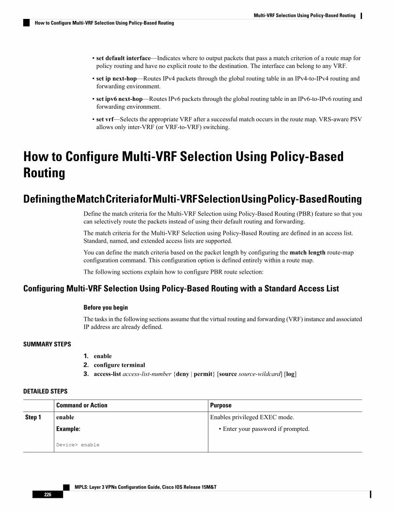
• set default interface—Indicates where to output packets that pass a match criterion of a route map forpolicy routing and have no explicit route to the destination. The interface can belong to any VRF.
• set ip next-hop—Routes IPv4 packets through the global routing table in an IPv4-to-IPv4 routing andforwarding environment.
• set ipv6 next-hop—Routes IPv6 packets through the global routing table in an IPv6-to-IPv6 routing andforwarding environment.
• set vrf—Selects the appropriate VRF after a successful match occurs in the route map. VRS-aware PSVallows only inter-VRF (or VRF-to-VRF) switching.
How to Configure Multi-VRF Selection Using Policy-BasedRouting
DefiningtheMatchCriteriaforMulti-VRFSelectionUsingPolicy-BasedRoutingDefine the match criteria for the Multi-VRF Selection using Policy-Based Routing (PBR) feature so that youcan selectively route the packets instead of using their default routing and forwarding.
The match criteria for the Multi-VRF Selection using Policy-Based Routing are defined in an access list.Standard, named, and extended access lists are supported.
You can define the match criteria based on the packet length by configuring thematch length route-mapconfiguration command. This configuration option is defined entirely within a route map.
The following sections explain how to configure PBR route selection:
Configuring Multi-VRF Selection Using Policy-Based Routing with a Standard Access List
Before you begin
The tasks in the following sections assume that the virtual routing and forwarding (VRF) instance and associatedIP address are already defined.
SUMMARY STEPS
1. enable2. configure terminal3. access-list access-list-number {deny | permit} [source source-wildcard] [log]
DETAILED STEPS
PurposeCommand or Action
Enables privileged EXEC mode.enableStep 1
Example: • Enter your password if prompted.
Device> enable
MPLS: Layer 3 VPNs Configuration Guide, Cisco IOS Release 15M&T226
Multi-VRF Selection Using Policy-Based RoutingHow to Configure Multi-VRF Selection Using Policy-Based Routing

PurposeCommand or Action
Enters global configuration mode.configure terminal
Example:
Step 2
Device# configure terminal
Creates an access list and defines the match criteria for theroute map.
access-list access-list-number {deny | permit} [sourcesource-wildcard] [log]
Step 3
Example: • Match criteria can be defined based on IP addresses,IP address ranges, and other IP packet access list
Device(config)# access-list 40 permit source10.1.1.0/24 0.0.0.255
filtering options. Named, numbered, standard, andextended access lists are supported. You can use allIP access list configuration options to define matchcriteria.
• The example creates a standard access list numbered40. This filter permits traffic from any host with an IPaddress in the 10.1.1.0/24 subnet.
Configuring Multi-VRF Selection Using Policy-Based Routing with a Named Extended Access ListTo configure Multi-VRF Selection using Policy-Based Routing (PBR) with a named extended access list,complete the following steps.
Before you begin
The tasks in the following sections assume that the virtual routing and forwarding (VRF) instance and associatedIP address are already defined.
SUMMARY STEPS
1. enable2. configure terminal3. ip access-list {standard | extended} [access-list-name | access-list-number]4. [sequence-number] {permit | deny} protocol source source-wildcard destination destination-wildcard
[option option-value] [precedence precedence] [tostos] [ttl operator-vaue] [log] [time-rangetime-range-name] [fragments]
DETAILED STEPS
PurposeCommand or Action
Enables privileged EXEC mode.enableStep 1
Example: • Enter your password if prompted.
Device> enable
Enters global configuration mode.configure terminal
Example:
Step 2
MPLS: Layer 3 VPNs Configuration Guide, Cisco IOS Release 15M&T227
Multi-VRF Selection Using Policy-Based RoutingConfiguring Multi-VRF Selection Using Policy-Based Routing with a Named Extended Access List

PurposeCommand or Action
Device# configure terminal
Specifies the IP access list type and enters the correspondingaccess list configuration mode.
ip access-list {standard | extended} [access-list-name |access-list-number]
Step 3
Example: • You can specify a standard, extended, or named accesslist.
Device(config)# ip access-list extended NAMEDACL
Defines the criteria for which the access list will permit ordeny packets.
[sequence-number] {permit | deny} protocol sourcesource-wildcard destination destination-wildcard [option
Step 4
option-value] [precedence precedence] [tostos] [ttl • Match criteria can be defined based on IP addresses,IP address ranges, and other IP packet access listoperator-vaue] [log] [time-range time-range-name]
[fragments] filtering options. Named, numbered, standard, andExample: extended access lists are supported. You can use all
IP access list configuration options to define matchcriteria.Device(config-ext-nacl)# permit ip any any option
any-options• The example creates a named access list that permitsany configured IP option.
Configuring Multi-VRF Selection in a Route MapIncoming packets are filtered through the match criteria that are defined in the route map. After a successfulmatch occurs, the set command configuration determines the VRF through which the outbound Virtual PrivateNetwork (VPN) packets will be policy routed.
Before you begin
You must define the virtual routing and forwarding (VRF) instance before you configure the route map;otherwise an error message appears on the console.
A receive entry must be added to the VRF selection table with the ip vrf receive command. If a match andset operation occurs in the route map but there is no receive entry in the local VRF table, the packet will bedropped if the packet destination is local.
SUMMARY STEPS
1. enable2. configure terminal3. named-ordering-route-map enable ]4. route-map map-tag [permit | deny] [sequence-number] [5. Do one of the following :
• set ip vrf vrf-name next-hop global-ipv4-address [...global-ipv4-address]• set ipv6 vrf vrf-name next-hop global-ipv6-address [...global-ipv6-address]• set ip next-hop recursive vrf global-ipv4-address [...global-ipv4-address]• set ip global next-hop global-ipv4-address [...global-ipv4-address]• set ipv6 global next-hop global-ipv6-address [...global-ipv6-address]
MPLS: Layer 3 VPNs Configuration Guide, Cisco IOS Release 15M&T228
Multi-VRF Selection Using Policy-Based RoutingConfiguring Multi-VRF Selection in a Route Map

6. Do one of the following:
• match ip address {acl-number [acl-name | acl-number]}• match length minimum-lengthmaximum-length
7. end
DETAILED STEPS
PurposeCommand or Action
Enables privileged EXEC mode.enableStep 1
Example: • Enter your password if prompted.
Device> enable
Enters global configuration mode.configure terminal
Example:
Step 2
Device# configure terminal
Enables ordering of route-maps based on a string providedby the user.
named-ordering-route-map enable ]
Example:
Step 3
Device(config)# named-ordering-route-map enable
Configures a route map and specifies how the packets areto be distributed. .
route-map map-tag [permit | deny] [sequence-number][
Example:
Step 4
Device(config)# route-map alpha permit ordering-seq
Indicates where to forward packets that pass a matchcriterion of a route map for policy routing when the IPv4next hop must be under a specified VRF.
Do one of the following :Step 5
• set ip vrf vrf-name next-hop global-ipv4-address[...global-ipv4-address]
Indicates where to forward packets that pass a matchcriterion of a route map for policy routing when the IPv6next hop must be under a specified VRF.
• set ipv6 vrf vrf-name next-hop global-ipv6-address[...global-ipv6-address]
• set ip next-hop recursive vrf global-ipv4-address[...global-ipv4-address] Indicates the IPv4 address to which destination or next hop
is used for packets that pass the match criterion configuredin the route map.
• set ip global next-hop global-ipv4-address[...global-ipv4-address]
• set ipv6 global next-hop global-ipv6-address[...global-ipv6-address] Indicates the IPv4 address to forward packets that pass a
match criterion of a route map for policy routing and forwhich the software uses the global routing table.Example:
Device(config-route-map)# set ip vrf myvrf next-hop10.0.0.0
Indicates the IPv6 address to forward packets that pass amatch criterion of a route map for policy routing and forwhich the software uses the global routing table.
Example:
MPLS: Layer 3 VPNs Configuration Guide, Cisco IOS Release 15M&T229
Multi-VRF Selection Using Policy-Based RoutingConfiguring Multi-VRF Selection in a Route Map
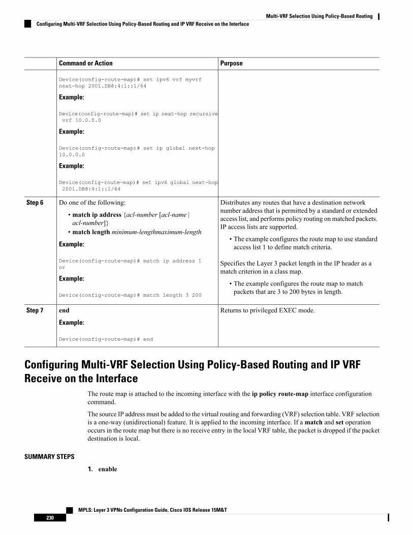
PurposeCommand or Action
Device(config-route-map)# set ipv6 vrf myvrfnext-hop 2001.DB8:4:1::1/64
Example:
Device(config-route-map)# set ip next-hop recursivevrf 10.0.0.0
Example:
Device(config-route-map)# set ip global next-hop10.0.0.0
Example:
Device(config-route-map)# set ipv6 global next-hop2001.DB8:4:1::1/64
Distributes any routes that have a destination networknumber address that is permitted by a standard or extended
Do one of the following:Step 6
• match ip address {acl-number [acl-name |acl-number]} access list, and performs policy routing onmatched packets.
IP access lists are supported.• match length minimum-lengthmaximum-length
• The example configures the route map to use standardaccess list 1 to define match criteria.Example:
Device(config-route-map)# match ip address 1or
Specifies the Layer 3 packet length in the IP header as amatch criterion in a class map.
Example:• The example configures the route map to matchpackets that are 3 to 200 bytes in length.Device(config-route-map)# match length 3 200
Returns to privileged EXEC mode.end
Example:
Step 7
Device(config-route-map)# end
Configuring Multi-VRF Selection Using Policy-Based Routing and IP VRFReceive on the Interface
The route map is attached to the incoming interface with the ip policy route-map interface configurationcommand.
The source IP address must be added to the virtual routing and forwarding (VRF) selection table. VRF selectionis a one-way (unidirectional) feature. It is applied to the incoming interface. If amatch and set operationoccurs in the route map but there is no receive entry in the local VRF table, the packet is dropped if the packetdestination is local.
SUMMARY STEPS
1. enable
MPLS: Layer 3 VPNs Configuration Guide, Cisco IOS Release 15M&T230
Multi-VRF Selection Using Policy-Based RoutingConfiguring Multi-VRF Selection Using Policy-Based Routing and IP VRF Receive on the Interface

2. configure terminal3. interface type number [name-tag]4. ip policy route-map map-tag5. ip vrf receive vrf-name6. end
DETAILED STEPS
PurposeCommand or Action
Enables privileged EXEC mode.enableStep 1
Example: • Enter your password if prompted.
Device> enable
Enters global configuration mode.configure terminal
Example:
Step 2
Device# configure terminal
Configures an interface and enters interface configurationmode.
interface type number [name-tag]
Example:
Step 3
Device(config)# interface FastEthernet 0/1/0
Identifies a route map to use for policy routing on aninterface.
ip policy route-map map-tag
Example:
Step 4
• The configuration example attaches the route mapnamed map1 to the interface.Device(config-if)# ip policy route-map map1
Adds the IP addresses that are associated with an interfaceinto the VRF table.
ip vrf receive vrf-name
Example:
Step 5
• This command must be configured for each VRF thatwill be used for VRF selection.Device(config-if)# ip vrf receive VRF-1
Returns to privileged EXEC mode.end
Example:
Step 6
Device(config-if)# end
Verifying theConfiguration ofMulti-VRF Selection UsingPolicy-Based RoutingTo verify the configuration of the Multi-VRF Selection Using Policy-Based Routing (PBR) feature, performthe following steps. You can enter the commands in any order.
MPLS: Layer 3 VPNs Configuration Guide, Cisco IOS Release 15M&T231
Multi-VRF Selection Using Policy-Based RoutingVerifying the Configuration of Multi-VRF Selection Using Policy-Based Routing

SUMMARY STEPS
1. show ip access-list [access-list-number | access-list-name]2. show route-map [map-name]3. show ip policy
DETAILED STEPS
Step 1 show ip access-list [access-list-number | access-list-name]
Verifies the configuration of match criteria for Multi-VRF Selection Using Policy-Based Routing. The command outputdisplays three subnet ranges defined as match criteria in three standard access lists:
Example:
Device# show ip access-list
Standard IP access list 4010 permit 10.1.0.0, wildcard bits 0.0.255.255Standard IP access list 5010 permit 10.2.0.0, wildcard bits 0.0.255.255Standard IP access list 6010 permit 10.3.0.0, wildcard bits 0.0.255.255
Step 2 show route-map [map-name]
Verifiesmatch and set commands within the route map:
Example:
Device# show route-map
The output displays the match criteria and set action for each route-map sequence. The output also displays the numberof packets and bytes that have been policy routed per each route-map sequence.
Example:
Device# show route-map map1
route-map map1, permit, sequence 10Match clauses:Set clauses:ip next-hop vrf myvrf 10.5.5.5 10.6.6.6 10.7.7.7ip next-hop global 10.8.8.8 10.9.9.9Policy routing matches: 0 packets, 0 bytesDevice# show route-map map2route-map map2, permit, sequence 10Match clauses:Set clauses:vrf myvrfPolicy routing matches: 0 packets, 0 bytesDevice# show route-map map3route-map map3, permit, sequence 10Match clauses:Set clauses:globalPolicy routing matches: 0 packets, 0 bytes
The following show route-map command displays output from the set ip vrf next-hop command:
MPLS: Layer 3 VPNs Configuration Guide, Cisco IOS Release 15M&T232
Multi-VRF Selection Using Policy-Based RoutingVerifying the Configuration of Multi-VRF Selection Using Policy-Based Routing

Example:
Device(config)# route-map test
Device(config-route-map)# set ip vrf myvrf next-hopDevice(config-route-map)# set ip vrf myvrf next-hop 192.168.3.2Device(config-route-map)# match ip address 255 101Device(config-route-map)# endDevice# show route-map
route-map test, permit, sequence 10Match clauses:ip address (access-lists): 101Set clauses:ip vrf myvrf next-hop 192.168.3.2Policy routing matches: 0 packets, 0 bytes
The following show route-map command displays output from the set ip global command:
Example:
Device(config)# route-map testDevice(config-route-map)# match ip address 255 101Device(config-route-map)# set ip global next-hop 192.168.4.2Device(config-route-map)# endDevice# show route-map
*May 25 13:45:55.551: %SYS-5-CONFIG_I: Configured from console by consoleout-maproute-map test, permit, sequence 10Match clauses:ip address (access-lists): 101Set clauses:ip global next-hop 192.168.4.2Policy routing matches: 0 packets, 0 bytes
Step 3 show ip policy
Verifies the Multi-VRF Selection Using Policy-Based Routing policy.
Example:
Device# show ip policy
The following show ip policy command output displays the interface and associated route map that is configured forpolicy routing:
Example:
Device# show ip policy
Interface Route mapFastEthernet0/1/0 PBR-VRF-Selection
MPLS: Layer 3 VPNs Configuration Guide, Cisco IOS Release 15M&T233
Multi-VRF Selection Using Policy-Based RoutingVerifying the Configuration of Multi-VRF Selection Using Policy-Based Routing

Configuration Examples for Multi-VRF Selection UsingPolicy-Based Routing
Example: Defining the Match Criteria for Multi-VRF Selection UsingPolicy-Based Routing
In the following example, three standard access lists are created to define match criteria for three differentsubnetworks. Any packets received on FastEthernet interface 0/1/0 will be policy routed through thePBR-VRF-Selection route map to the virtual routing and forwarding (VRF) that is matched in the sameroute-map sequence. If the source IP address of the packet is part of the 10.1.0.0/24 subnet, VRF1 will beused for routing and forwarding.
access-list 40 permit source 10.1.0.0 0.0.255.255access-list 50 permit source 10.2.0.0 0.0.255.255access-list 60 permit source 10.3.0.0 0.0.255.255route-map PBR-VRF-Selection permit 10match ip address 40set vrf VRF1!route-map PBR-VRF-Selection permit 20match ip address 50set vrf VRF2!route-map PBR-VRF-Selection permit 30match ip address 60set vrf VRF3!interface FastEthernet 0/1/0ip address 192.168.1.6 255.255.255.252ip policy route-map PBR-VRF-Selectionip vrf receive VRF1ip vrf receive VRF2ip vrf receive VRF3
Example: Configuring Multi-VRF Selection in a Route MapThe following example shows a set ip vrf next-hop command that applies policy-based routing to the virtualrouting and forwarding (VRF) interface named myvrf and specifies that the IP address of the next hop is10.0.0.2:
Device(config)# route-map map1 permitDevice(config)# set vrf myvrfDevice(config-route-map)# set ip vrf myvrf next-hop 10.0.0.2Device(config-route-map)# match ip address 101Device(config-route-map)# end
The following example shows a set ip global command that specifies that the device should use the next hopaddress 10.0.0.1 in the global routing table:
Device(config-route-map)# set ip global next-hop 10.0.0.1
MPLS: Layer 3 VPNs Configuration Guide, Cisco IOS Release 15M&T234
Multi-VRF Selection Using Policy-Based RoutingConfiguration Examples for Multi-VRF Selection Using Policy-Based Routing
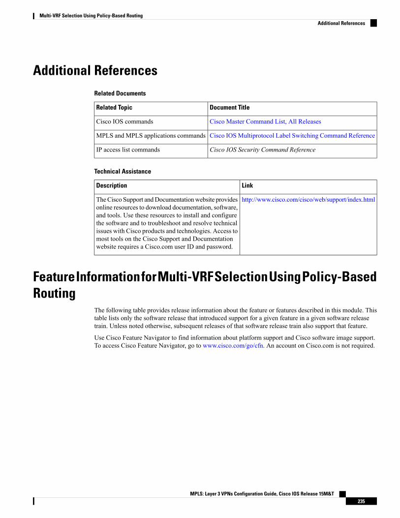
Additional ReferencesRelated Documents
Document TitleRelated Topic
Cisco Master Command List, All ReleasesCisco IOS commands
Cisco IOSMultiprotocol Label Switching Command ReferenceMPLS and MPLS applications commands
Cisco IOS Security Command ReferenceIP access list commands
Technical Assistance
LinkDescription
http://www.cisco.com/cisco/web/support/index.htmlTheCisco Support andDocumentationwebsite providesonline resources to download documentation, software,and tools. Use these resources to install and configurethe software and to troubleshoot and resolve technicalissues with Cisco products and technologies. Access tomost tools on the Cisco Support and Documentationwebsite requires a Cisco.com user ID and password.
FeatureInformationforMulti-VRFSelectionUsingPolicy-BasedRouting
The following table provides release information about the feature or features described in this module. Thistable lists only the software release that introduced support for a given feature in a given software releasetrain. Unless noted otherwise, subsequent releases of that software release train also support that feature.
Use Cisco Feature Navigator to find information about platform support and Cisco software image support.To access Cisco Feature Navigator, go to www.cisco.com/go/cfn. An account on Cisco.com is not required.
MPLS: Layer 3 VPNs Configuration Guide, Cisco IOS Release 15M&T235
Multi-VRF Selection Using Policy-Based RoutingAdditional References
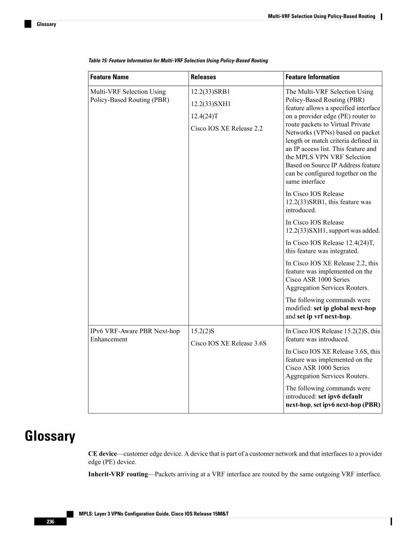
Table 15: Feature Information for Multi-VRF Selection Using Policy-Based Routing
Feature InformationReleasesFeature Name
The Multi-VRF Selection UsingPolicy-Based Routing (PBR)feature allows a specified interfaceon a provider edge (PE) router toroute packets to Virtual PrivateNetworks (VPNs) based on packetlength or match criteria defined inan IP access list. This feature andthe MPLS VPN VRF SelectionBased on Source IP Address featurecan be configured together on thesame interface
In Cisco IOS Release12.2(33)SRB1, this feature wasintroduced.
In Cisco IOS Release12.2(33)SXH1, support was added.
In Cisco IOS Release 12.4(24)T,this feature was integrated.
In Cisco IOS XE Release 2.2, thisfeature was implemented on theCisco ASR 1000 SeriesAggregation Services Routers.
The following commands weremodified: set ip global next-hopand set ip vrf next-hop.
12.2(33)SRB1
12.2(33)SXH1
12.4(24)T
Cisco IOS XE Release 2.2
Multi-VRF Selection UsingPolicy-Based Routing (PBR)
In Cisco IOS Release 15.2(2)S, thisfeature was introduced.
In Cisco IOS XE Release 3.6S, thisfeature was implemented on theCisco ASR 1000 SeriesAggregation Services Routers.
The following commands wereintroduced: set ipv6 defaultnext-hop, set ipv6 next-hop (PBR)
15.2(2)S
Cisco IOS XE Release 3.6S
IPv6 VRF-Aware PBR Next-hopEnhancement
GlossaryCE device—customer edge device. A device that is part of a customer network and that interfaces to a provideredge (PE) device.
Inherit-VRF routing—Packets arriving at a VRF interface are routed by the same outgoing VRF interface.
MPLS: Layer 3 VPNs Configuration Guide, Cisco IOS Release 15M&T236
Multi-VRF Selection Using Policy-Based RoutingGlossary
Inter-VRF routing—Packets arriving at a VRF interface are routed via any other outgoing VRF interface.
IP—Internet Protocol. Network layer protocol in the TCP/IP stack offering a connectionless internetworkservice. IP provides features for addressing, type-of-service specification, fragmentation and reassembly, andsecurity. Defined in RFC 791.
PBR—policy-based routing. PBR allows a user to manually configure how received packets should be routed.
PE device—provider edge device. A device that is part of a service provider’s network and that is connectedto a CE device. It exchanges routing information with CE devices by using static routing or a routing protocolsuch as BGP, RIPv1, or RIPv2.
VPN—Virtual Private Network. A collection of sites sharing a common routing table. A VPN provides asecure way for customers to share bandwidth over an ISP backbone network.
VRF—AVPN routing and forwarding instance. A VRF consists of an IP routing table, a derived forwardingtable, a set of interfaces that use the forwarding table, and a set of rules and routing protocols that determinewhat goes into the forwarding table.
VRF-lite—A feature that enables a service provider to support two or more VPNs, where IP addresses canbe overlapped among the VPNs.
MPLS: Layer 3 VPNs Configuration Guide, Cisco IOS Release 15M&T237
Multi-VRF Selection Using Policy-Based RoutingGlossary

MPLS: Layer 3 VPNs Configuration Guide, Cisco IOS Release 15M&T238
Multi-VRF Selection Using Policy-Based RoutingGlossary

C H A P T E R 15MPLS VPN VRF Selection Based on a Source IPAddress
The MPLS VPN VRF Selection Based on a Source IP Address feature allows a specified interface on aprovider edge (PE) device to route packets to different Virtual Private Networks (VPNs) based on the sourceIP address of the packet. This feature is an improvement over using a policy-based device to route packets todifferent VPNs.
The MPLS VPN VRF Selection Based on a Source IP Address feature allows packets arriving on an interfaceto be switched into the appropriate virtual routing and forwarding (VRF) table based upon the source IPaddress of the packets. Once the packets have been “selected” into the correct VRF routing table, they areprocessed normally, based on the destination address and forwarded through the rest of the MultiprotocolLabel Switching (MPLS) VPN.
In most cases, this feature is a "one way" feature; it works on packets coming from the end users to the PEdevice
• Finding Feature Information, on page 239• Prerequisites for MPLS VPN VRF Selection Based on a Source IP Address, on page 240• Restrictions for MPLS VPN VRF Selection Based on a Source IP Address, on page 241• Information About MPLS VPN VRF Selection Based on a Source IP Address, on page 241• How to Configure MPLS VPN VRF Selection Based on a Source IP Address, on page 246• Configuration Examples for MPLS VPN VRF Selection Based on a Source IP Address, on page 249• Additional References, on page 251• Feature Information for MPLS VPN VRF Selection Based on a Source IP Address, on page 251
Finding Feature InformationYour software release may not support all the features documented in this module. For the latest caveats andfeature information, see Bug Search Tool and the release notes for your platform and software release. Tofind information about the features documented in this module, and to see a list of the releases in which eachfeature is supported, see the feature information table.
Use Cisco Feature Navigator to find information about platform support and Cisco software image support.To access Cisco Feature Navigator, go to www.cisco.com/go/cfn. An account on Cisco.com is not required.
MPLS: Layer 3 VPNs Configuration Guide, Cisco IOS Release 15M&T239
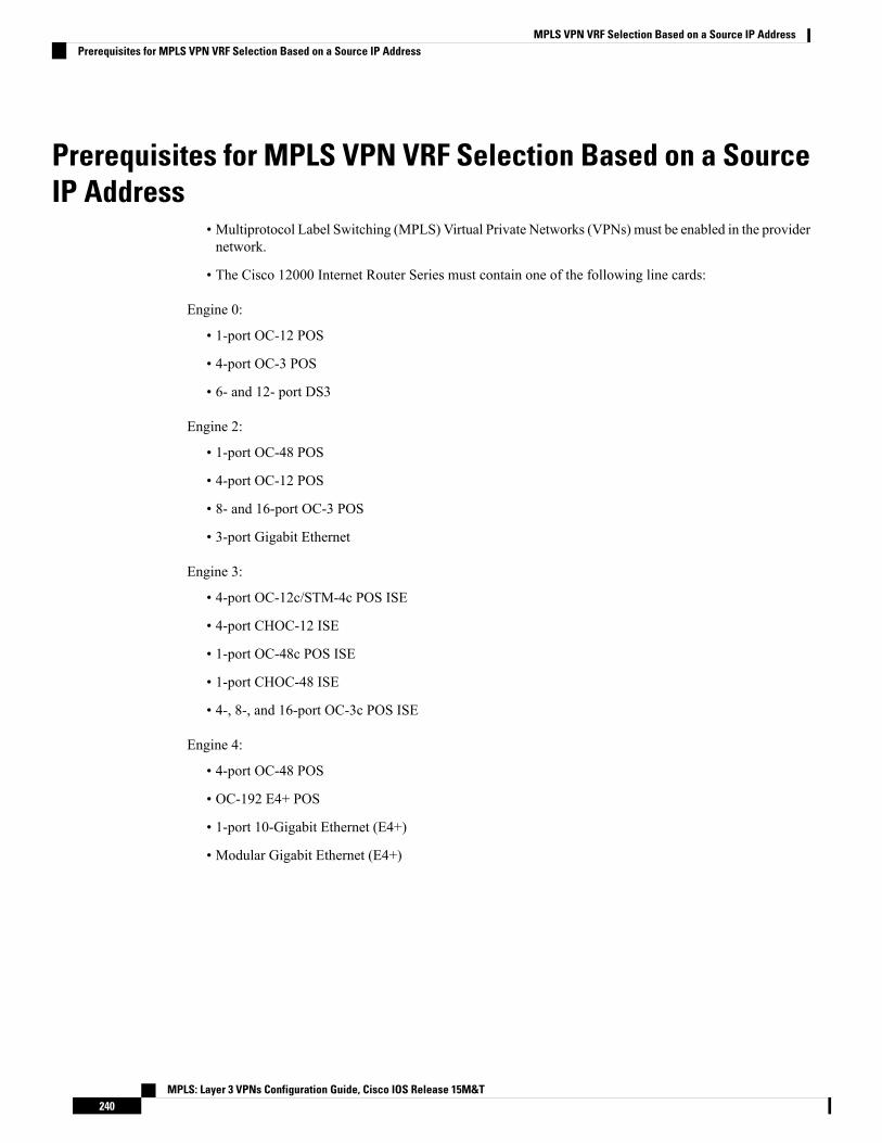
Prerequisites for MPLS VPN VRF Selection Based on a SourceIP Address
• Multiprotocol Label Switching (MPLS) Virtual Private Networks (VPNs) must be enabled in the providernetwork.
• The Cisco 12000 Internet Router Series must contain one of the following line cards:
Engine 0:
• 1-port OC-12 POS
• 4-port OC-3 POS
• 6- and 12- port DS3
Engine 2:
• 1-port OC-48 POS
• 4-port OC-12 POS
• 8- and 16-port OC-3 POS
• 3-port Gigabit Ethernet
Engine 3:
• 4-port OC-12c/STM-4c POS ISE
• 4-port CHOC-12 ISE
• 1-port OC-48c POS ISE
• 1-port CHOC-48 ISE
• 4-, 8-, and 16-port OC-3c POS ISE
Engine 4:
• 4-port OC-48 POS
• OC-192 E4+ POS
• 1-port 10-Gigabit Ethernet (E4+)
• Modular Gigabit Ethernet (E4+)
MPLS: Layer 3 VPNs Configuration Guide, Cisco IOS Release 15M&T240
MPLS VPN VRF Selection Based on a Source IP AddressPrerequisites for MPLS VPN VRF Selection Based on a Source IP Address

Restrictions for MPLS VPN VRF Selection Based on a SourceIP Address
• The MPLS VPN VRF Selection Based on a Source IP Address feature is supported only in ServiceProvider (-p-) images.
• The Cisco software must support Multiprotocol Label Switching (MPLS) Virtual Private Networks(VPNs), and the provider network must have MPLS Label Distribution Protocol (LDP) installed andrunning.
• The MPLS VPN VRF Selection Based on a Source IP Address feature is a unidirectional feature andcan only be used from a customer (IP-based) network for a connection to a provider (MPLS-based)network and cannot be used from a provider network to a customer network.
• Subnet masks should be kept as short as possible for the MPLS VPN VRF Selection Based on a SourceIP Address criteria for Engine 2 line cards. The performance of this feature can degrade with longersubnet masks (/24 or /32, for example).
• Cisco Express Forwarding must be enabled on any interfaces that have the MPLS VPN VRF SelectionBased on a Source IP Address feature enabled. Distributed Cisco Express Forwarding is enabled bydefault on Cisco 12000 Series Internet routers.
• An IP traceroute command from an MPLS VPN VRF Selection customer edge (CE) device to a typicalMPLS VPN VRF CE device works as expected. However, an IP traceroute command from a typicalMPLS VPN VRF CE device to an MPLS VPN VRF Selection CE device might fail to show all therelevant hop information across the core.
Information About MPLS VPN VRF Selection Based on a SourceIP Address
VRF Selection ProcessThe MPLS VPN VRF Selection Based on a Source IP Address feature uses the process described in thissection to route packets from the customer networks to the provider edge (PE) device and into the providernetwork.
A two-table lookup mechanism is used at the ingress interface of the PE device to determine the routing andforwarding of packets coming from the customer networks, which use IP protocols, to theMultiprotocol LabelSwitching (MPLS) Virtual Private Networks (VPNs), which use MPLS protocols.
• The first table, the VRF Selection table, is used to compare the source IP address of the packet with alist of IP addresses in the table. Each IP address in the table is associated with an MPLS VPN. If a matchis found between the source IP address of the packet and an IP address in the VRF Selection table, thepacket is routed to the second table (the VRF table) or the routing table for the appropriate VPN.
If no match is found in the table for the source IP address of the packet, the packet is either routed viathe global routing table used by the PE device (this is the default behavior), or is dropped.
MPLS: Layer 3 VPNs Configuration Guide, Cisco IOS Release 15M&T241
MPLS VPN VRF Selection Based on a Source IP AddressRestrictions for MPLS VPN VRF Selection Based on a Source IP Address

• The second table, the VRF table (also known as the VPN routing table), contains the virtual routing andforwarding information for the specified VPN and is used to forward the selected VPN traffic to thecorrect MPLS label switched path (LSP) based upon the destination IP address of the packet.
The VRF Selection process removes the association between the VPN and the interface and allows more thanone MPLS VPN to be associated with the interface.
VRF Selection ExamplesHere is an example of the MPLS VPN VRF Selection Based on a Source IP Address feature. It is based on anetwork carrier that allows subscribers to the carrier to choose frommultiple Internet service providers (ISPs)for Internet access. The figure below provides an example of the MPLS VPN VRF Selection Based on aSource IP Address feature with an IP-based host network, an Multiprotocol Label Switching (MPLS) VirtualPrivate Network (VPN) , and three ISPs connected to the MPLS VPN network.Figure 15: VRF Selection Implementation Example
MPLS: Layer 3 VPNs Configuration Guide, Cisco IOS Release 15M&T242
MPLS VPN VRF Selection Based on a Source IP AddressVRF Selection Examples

ISPs 1 to 3 provide a list of IP addresses to Carrier X so thateach host in the “POOL” network can be properly addressed.This host addressing would most likely be done by means ofthe DHCP or DNS services of Carrier X.
2PE2 is acting as a VRF selector and asa typicalMPLSVPNPE device to CE2and CE3.
1
In the figure above, Carrier X represents the network carrier; Host A, Host B and Host C represent the carriersubscribers; and ISP 1, ISP 2 and ISP 3 represent the ISPs.
The figure illustrates a packet traveling from Host A to ISP 1. The dashed line represents the travel of thepacket.
Host A chooses ISP 1 to use as its ISP. Carrier X will provide an IP address to Host A that falls within therange of the ISP 1 registered network addresses. Based upon this IP address allocation, the VRF Selectioncriteria are set.
The POOL network, by using default routes, forwards traffic from the Carrier X IP-based (POOL) networkto the Carrier XMPLS-based VPN network. TheMPLS VPN network forwards (shunts) the traffic from HostA into the correct VPN, which is VPN 1 (ISP 1), by using the VRF Selection-enabled device PE2.
To enable the MPLS VPN VRF Selection Based on a Source IP Address feature on the devices PE1 and PE2,enter the following commands:
Device(config)# vrf selection source 10.1.0.0 255.255.0.0 vrf vpn1Device(config)# vrf selection source 172.16.0.0 255.255.0.0 vrf vpn2Device(config)# interface POS1/0Device(config-if)# description Link to CE POS1/0Device(config-if)# ip vrf select source
Traffic coming from the ISPs to the hosts (in the example, traffic traveling from the ISPs on the right to thehosts on the left) is not affected by the MPLS VPN VRF Selection Based on a Source IP Address feature anddoes not have to be returned via an MPLS path. This traffic can return via the shortest available IP path.
Another example of MPLS VPN VRF Selection Based on a Source IP Address feature in use might involvea cable modem termination system (CMTS). If the owner of the CMTSwants to allow cablemodem subscribersto choose their ISP from a group of ISPs, theMPLSVPNVRF Selection Based on a Source IP Address featureprovides a fast and scalable solution.
VRF Selection is a Unidirectional FeatureIn the figure above, the end users are typical Internet home users. If the MPLS VPN VRF Selection Basedon a Source IP Address feature were a two-way (bidirectional) feature, traffic coming from the Internet serviceproviders (ISPs) to the hosts would be required to use only the provider edge (PE) devices that have MPLSVPN VRF Selection Based on a Source IP Address feature enabled, which might cause performance issues.
When traffic from the POOL network goes through the carrier network to the ISP networks for Internet access,the traffic in the carrier network must be forwarded by means of Multiprotocol Label Switching (MPLS)Virtual Private Network (VPN) paths, because the VRF Selection-enabled device has “selected” the trafficinto the correct MPLS VPN.
Traffic from the ISP networks to the POOL network does not have to use MPLS VPN paths in the carriernetwork and can use the path that seems most efficient to return to the POOL network. This traffic can use apath that uses either MPLS or IP for routing and forwarding and does not have to travel via an MPLS VPN.
Traffic from the ISP networks to the POOL networks can be forwarded by the global routing table used byevery interface. One way to accomplish this is to enter virtual routing and forwarding (VRF) static routes on
MPLS: Layer 3 VPNs Configuration Guide, Cisco IOS Release 15M&T243
MPLS VPN VRF Selection Based on a Source IP AddressVRF Selection is a Unidirectional Feature

the PE device interfaces connected to the ISPs. The VRF static routes would route traffic from the ISPs to thecarrier network.
Establishing static VRF routes allows traffic from the ISPs to enter the carrier network as traffic that can onlybe routed by using the global routing table toward the POOL network.
If the ISPs are not providing global host address space, or the MPLS VPN VRF Selection Based on a SourceIP Address feature is not being used to route Internet traffic, the PE interfaces connected to the ISPs must beplaced into a VRF. If the PE interfaces are using VRFs for routing traffic from the ISPs, all traffic from theISPs to the hosts through the carrier network would be forwarded by MPLS VPN paths, and performancewould not be as good as if IP forwarding were used.
Normal IP-based VPN operations, such as populating the routing information base (RIB) and forwardinginformation base (FIB) from a routing protocol such as Border Gateway Protocol (BGP), are used to routeand forward packets within the various VPNs in the customer networks. The provider network usesMPLS-basedrouting protocols to perform VPN routing and forwarding inside the provider network.
Conditions Under Which VRF Selection Becomes BidirectionalForwarding of traffic from the carrier network to the POOL network by using the global routing table ispossible only if the Internet service providers (ISPs) have provided registered IP address space for all of thesubscribed users within the POOL network.
If the POOL network uses IP addresses that are not globally routeable and are designed for a nonconnectedenterprise (defined by RFC1918), the MPLS VPN VRF Selection Based on a Source IP Address featurebecomes bidirectional. All traffic being sent and received by the host would have to travel via a device thathas theMPLSVPNVRF Selection Based on a Source IP Address feature enabled. The POOL network cannotbe addressed with overlapping address space, regardless of the type of address space being used.
Advantages of VRF Selection over Per-Interface IP VPN ConfigurationThe MPLS VPN VRF Selection Based on a Source IP Address feature removes the association between aVirtual Private Network (VPN) and an interface. Before the MPLS VPN VRF Selection Based on a SourceIP Address feature was introduced, the following implementation was used to route outgoing MultiprotocolLabel Switching (MPLS) VPN packets to different destinations:
• A policy-based device (PBR) is attached to the customer edge (CE) device.
• The egress side of the PBR device side has VLANs connected to a provider edge (PE) device.
• The PBR device uses a policy-based route map to select the correct output (VLAN) interface, and eachVLAN is under a specific VRF. The figure below illustrates a sample configuration in which a PBRdevice is used for routing MPLS packets to different destinations.
MPLS: Layer 3 VPNs Configuration Guide, Cisco IOS Release 15M&T244
MPLS VPN VRF Selection Based on a Source IP AddressConditions Under Which VRF Selection Becomes Bidirectional

Figure 16: Implementation of Multiple VPNs Before VRF Selection
The following limitations apply to PBR-based solutions that use this implementation:
• Policy routing and MPLS VPN functions cannot be performed on the same platform. Integration into asingle platform is critical for manageability and support.
• Each VRF is limited to one VPN per interface, which limits scalability.
• There is no network redundancy.
• The PBR is the only point of connection for all the networks attached to the PBR. The capacity and theperformance capabilities of the PBR device are critical.
• There is no diversity in the connectivity to the networks.
• Every network is required to connect to every PBR. If every network is not connected to every PBR,packets from the end user to the PBR are dropped because the PBR has no way of switching the IP trafficproperly.
• Adding multiple PBRs that are interconnected introduces more network policy-routed hops.
TheMPLSVPNVRF Selection Based on a Source IP Address feature addresses the limitations of and problemswith using a PBR for packet routing and forwarding.
Benefits of MPLS VPN VRF Selection Based on a Source IP AddressThe following are benefits to using the MPLS VPN VRF Selection Based on a Source IP Address method ofVPN routing and forwarding.
• Association of VPN to interface is removed—The MPLS VPN VRF Selection Based on a Source IPAddress feature removes the association between a Virtual Private Network (VPN) and an interface, thusallowing packets from the host network to the provider network to have more than one VPN availableper interface.
• Access to every customer network is possible from every provider edge (PE) device in the providernetwork-Access points to each network can be established at any MPLS PE device and can be maderedundant by connections to multiple PE devices (for example, the CE2 device in the figure above).
MPLS: Layer 3 VPNs Configuration Guide, Cisco IOS Release 15M&T245
MPLS VPN VRF Selection Based on a Source IP AddressBenefits of MPLS VPN VRF Selection Based on a Source IP Address
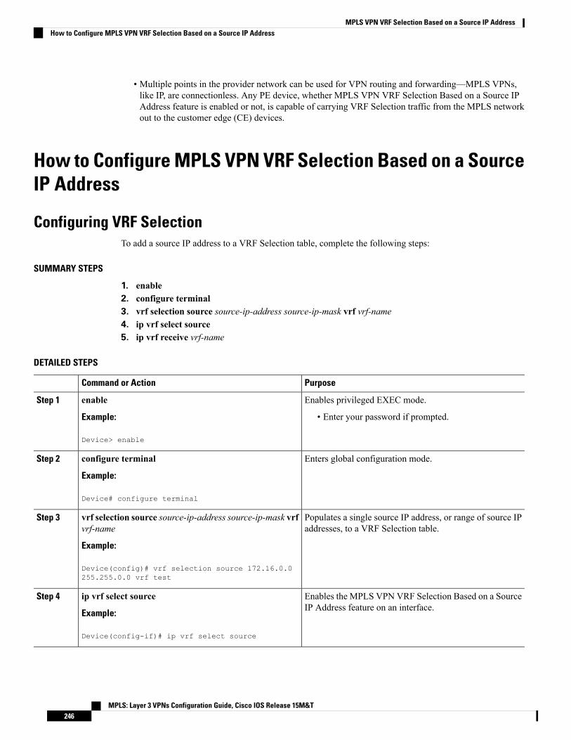
• Multiple points in the provider network can be used for VPN routing and forwarding—MPLS VPNs,like IP, are connectionless. Any PE device, whether MPLS VPN VRF Selection Based on a Source IPAddress feature is enabled or not, is capable of carrying VRF Selection traffic from the MPLS networkout to the customer edge (CE) devices.
How to Configure MPLS VPN VRF Selection Based on a SourceIP Address
Configuring VRF SelectionTo add a source IP address to a VRF Selection table, complete the following steps:
SUMMARY STEPS
1. enable2. configure terminal3. vrf selection source source-ip-address source-ip-mask vrf vrf-name4. ip vrf select source5. ip vrf receive vrf-name
DETAILED STEPS
PurposeCommand or Action
Enables privileged EXEC mode.enableStep 1
Example: • Enter your password if prompted.
Device> enable
Enters global configuration mode.configure terminal
Example:
Step 2
Device# configure terminal
Populates a single source IP address, or range of source IPaddresses, to a VRF Selection table.
vrf selection source source-ip-address source-ip-mask vrfvrf-name
Example:
Step 3
Device(config)# vrf selection source 172.16.0.0255.255.0.0 vrf test
Enables the MPLS VPN VRF Selection Based on a SourceIP Address feature on an interface.
ip vrf select source
Example:
Step 4
Device(config-if)# ip vrf select source
MPLS: Layer 3 VPNs Configuration Guide, Cisco IOS Release 15M&T246
MPLS VPN VRF Selection Based on a Source IP AddressHow to Configure MPLS VPN VRF Selection Based on a Source IP Address

PurposeCommand or Action
Adds all the IP addresses that are associated with aninterface into a VRF table.
ip vrf receive vrf-name
Example:
Step 5
Device(config-if)# ip vrf receive red
Establishing IP Static Routes for a VRF InstanceTraffic coming from the Internet service providers (ISPs) to the hosts does not require the use of theMultiprotocol Label Switching (MPLS) Virtual Private Network (VPN) paths; this traffic can use the shortestIP route back to the host.
VPN static routes for traffic returning to the customer networks are only necessary if VPN traffic returningto the customer networks is being forwarded from the MPLS VPN VRF Selection Based on a Source IPAddress interface. The remote provider edge (PE) device could also be configured to route return traffic tothe customer networks directly by using the global routing table.
SUMMARY STEPS
1. enable2. configure terminal3. ip route vrf vrf-name prefix mask [next-hop-address] {[interface interface-number}] [global] [distance]
[permanent] [tag]
DETAILED STEPS
PurposeCommand or Action
Enables privileged EXEC mode.enableStep 1
Example: • Enter your password if prompted.
Device> enable
Enters global configuration mode.configure terminal
Example:
Step 2
Device# configure terminal
Establishes static routes for a VRF.ip route vrf vrf-name prefix mask [next-hop-address]{[interface interface-number}] [global] [distance][permanent] [tag]
Step 3
Example:
Device(config-if)# ip route vrf vpn1 172.16.0.0255.255.0.0 POS1/0
MPLS: Layer 3 VPNs Configuration Guide, Cisco IOS Release 15M&T247
MPLS VPN VRF Selection Based on a Source IP AddressEstablishing IP Static Routes for a VRF Instance
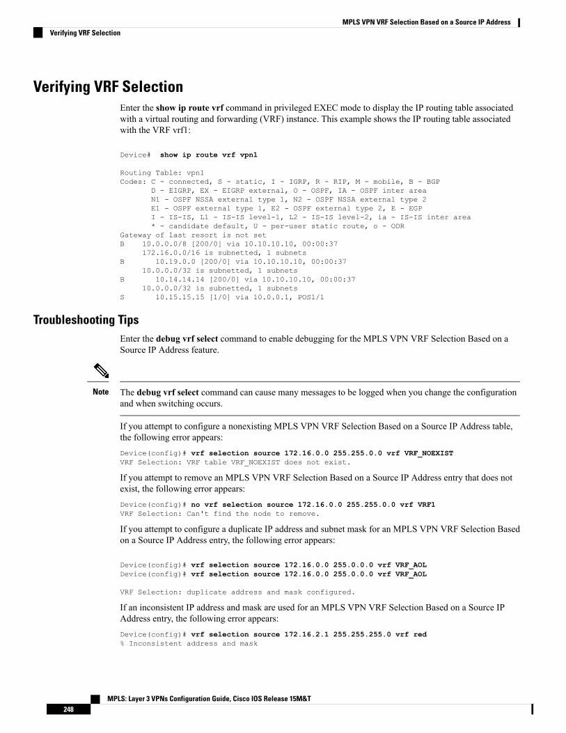
Verifying VRF SelectionEnter the show ip route vrf command in privileged EXEC mode to display the IP routing table associatedwith a virtual routing and forwarding (VRF) instance. This example shows the IP routing table associatedwith the VRF vrf1:
Device# show ip route vrf vpn1
Routing Table: vpn1Codes: C - connected, S - static, I - IGRP, R - RIP, M - mobile, B - BGP
D - EIGRP, EX - EIGRP external, O - OSPF, IA - OSPF inter areaN1 - OSPF NSSA external type 1, N2 - OSPF NSSA external type 2E1 - OSPF external type 1, E2 - OSPF external type 2, E - EGPI - IS-IS, L1 - IS-IS level-1, L2 - IS-IS level-2, ia - IS-IS inter area* - candidate default, U - per-user static route, o - ODR
Gateway of last resort is not setB 10.0.0.0/8 [200/0] via 10.10.10.10, 00:00:37
172.16.0.0/16 is subnetted, 1 subnetsB 10.19.0.0 [200/0] via 10.10.10.10, 00:00:37
10.0.0.0/32 is subnetted, 1 subnetsB 10.14.14.14 [200/0] via 10.10.10.10, 00:00:37
10.0.0.0/32 is subnetted, 1 subnetsS 10.15.15.15 [1/0] via 10.0.0.1, POS1/1
Troubleshooting TipsEnter the debug vrf select command to enable debugging for the MPLS VPN VRF Selection Based on aSource IP Address feature.
The debug vrf select command can cause many messages to be logged when you change the configurationand when switching occurs.
Note
If you attempt to configure a nonexisting MPLS VPN VRF Selection Based on a Source IP Address table,the following error appears:Device(config)# vrf selection source 172.16.0.0 255.255.0.0 vrf VRF_NOEXISTVRF Selection: VRF table VRF_NOEXIST does not exist.
If you attempt to remove an MPLS VPN VRF Selection Based on a Source IP Address entry that does notexist, the following error appears:Device(config)# no vrf selection source 172.16.0.0 255.255.0.0 vrf VRF1VRF Selection: Can't find the node to remove.
If you attempt to configure a duplicate IP address and subnet mask for an MPLS VPN VRF Selection Basedon a Source IP Address entry, the following error appears:
Device(config)# vrf selection source 172.16.0.0 255.0.0.0 vrf VRF_AOLDevice(config)# vrf selection source 172.16.0.0 255.0.0.0 vrf VRF_AOL
VRF Selection: duplicate address and mask configured.
If an inconsistent IP address and mask are used for an MPLS VPN VRF Selection Based on a Source IPAddress entry, the following error appears:Device(config)# vrf selection source 172.16.2.1 255.255.255.0 vrf red% Inconsistent address and mask
MPLS: Layer 3 VPNs Configuration Guide, Cisco IOS Release 15M&T248
MPLS VPN VRF Selection Based on a Source IP AddressVerifying VRF Selection
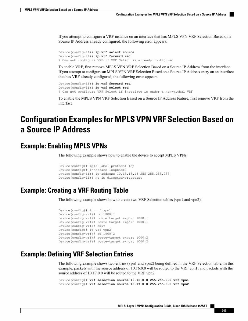
If you attempt to configure a VRF instance on an interface that has MPLS VPN VRF Selection Based on aSource IP Address already configured, the following error appears:
Device(config-if)# ip vrf select sourceDevice(config-if)# ip vrf forward red% Can not configure VRF if VRF Select is already configured
To enable VRF, first remove MPLS VPN VRF Selection Based on a Source IP Address from the interface.If you attempt to configure an MPLS VPNVRF Selection Based on a Source IP Address entry on an interfacethat has VRF already configured, the following error appears:Device(config-if)# ip vrf forward redDevice(config-if)# ip vrf select red% Can not configure VRF Select if interface is under a non-global VRF
To enable the MPLS VPN VRF Selection Based on a Source IP Address feature, first remove VRF from theinterface
Configuration Examples for MPLS VPN VRF Selection Based ona Source IP Address
Example: Enabling MPLS VPNsThe following example shows how to enable the device to accept MPLS VPNs:
Device(config)# mpls label protocol ldpDevice(config)# interface loopback0Device(config-if)# ip address 10.13.13.13 255.255.255.255Device(config-if)# no ip directed-broadcast
Example: Creating a VRF Routing TableThe following example shows how to create two VRF Selection tables (vpn1 and vpn2):
Device(config)# ip vrf vpn1Device(config-vrf)# rd 1000:1Device(config-vrf)# route-target export 1000:1Device(config-vrf)# route-target import 1000:1Device(config-vrf)# exitDevice(config)# ip vrf vpn2Device(config-vrf)# rd 1000:2Device(config-vrf)# route-target export 1000:2Device(config-vrf)# route-target export 1000:2
Example: Defining VRF Selection EntriesThe following example shows two entries (vpn1 and vpn2) being defined in the VRF Selection table. In thisexample, packets with the source address of 10.16.0.0 will be routed to the VRF vpn1, and packets with thesource address of 10.17.0.0 will be routed to the VRF vpn2:Device(config)# vrf selection source 10.16.0.0 255.255.0.0 vrf vpn1Device(config)# vrf selection source 10.17.0.0 255.255.0.0 vrf vpn2
MPLS: Layer 3 VPNs Configuration Guide, Cisco IOS Release 15M&T249
MPLS VPN VRF Selection Based on a Source IP AddressConfiguration Examples for MPLS VPN VRF Selection Based on a Source IP Address

Example: Defining IP Static Routes for a VRFThe following example shows IP static routes being created for two VRFs (vpn1 and vpn2) for the POS1/0interface:Device(config)# ip route vrf vpn1 10.16.0.0 255.255.0.0 POS1/0Device(config)# ip route vrf vpn2 10.17.0.0 255.255.0.0 POS1/0
Example: Configuring an Interface for VRF SelectionThe following example shows the POS1/0 interface being configured for the MPLS VPN VRF SelectionBased on a Source IP Address feature and the configured IP address (31.0.0.1) being added to the VRFs vpn1and vpn2 as connected routes:
Device(config)# interface POS1/0Device(config-if)# description Link to CE1 POS1/0 (eng2)Device(config-if)# ip vrf select sourceDevice(config-if)# ip vrf receive vpn1Device(config-if)# ip vrf receive vpn2Device(config-if)# ip address 10.0.0.1 255.0.0.0Device(config-if)# no ip directed-broadcastDevice(config-if)# load-interval 30Device(config-if)# crc 32Device(config-if)# end
Example: Configuring a BGP Device for VRF SelectionA device that is enable with the MPLS VPN VRF Selection Based on a Source IP Address feature requiresan MPLS VPN BGP configuration. The following example configures a device that is using BGP for theMPLS VPN VRF Selection Based on a Source IP Address feature:
Device(config)# router bgp 1000Device(config-router)# no bgp default ipv4-unicastDevice(config-router)# bgp log-neighbor-changesDevice(config-router)# timers bgp 10 30Device(config-router)# neighbor 10.11.11.11 remote-as 1000Device(config-router)# neighbor 10.11.11.11 update-source Loopback0Device(config-router)# no auto-summaryDevice(config-router)# address-family vpnv4Device(config-router-af)# neighbor 10.11.11.11 activateDevice(config-router-af)# neighbor 10.11.11.11 send-community extendedDevice(config-router-af)# exit-address-familyDevice(config-router)# address-family ipv4 vrf vpn2Device(config-router-af)# redistribute staticDevice(config-router-af)# no auto-summaryDevice(config-router-af)# no synchronizationDevice(config-router-af)# exit-address-familyDevice(config-router)# address-family ipv4 vrf vpn1Device(config-router-af)# redistribute staticDevice(config-router-af)# no auto-summaryDevice(config-router-af)# no synchronizationDevice(config-router-af)# exit-address-family
MPLS: Layer 3 VPNs Configuration Guide, Cisco IOS Release 15M&T250
MPLS VPN VRF Selection Based on a Source IP AddressExample: Defining IP Static Routes for a VRF

Example: Configuring a VRF to Eliminate Unnecessary Packet ForwardingIf a packet arrives at an interface that has theMPLSVPNVRF Selection Based on a Source IP Address featureenabled, and the packet source IP address does not match any VRF selection definition, that packet will beforwarded by means of the global routing table. This default behavior could cause problems if IP addressspoofing is being implemented. Unnecessary traffic could be forwarded by the global routing table. To eliminatethis unnecessary routing of packets, create a VRF selection definition that will forward all unknown incomingtraffic to a null interface.
The following configuration causes all traffic not matching a more specific VRF selection definition to berouted to the Null0 interface, thus causing the packets to be dropped.
Device(config)# ip vrf VRF_DROPDevice(config-vrf)# rd 999:99Device(config-vrf)# route-target export 999:99Device(config-vrf)# route-target import 999:99Device(config-vrf)# exitDevice(config)# vrf selection source 0.0.0.0 0.0.0.0 vrf VRF_DROPDevice(config)# ip route vrf VRF_DROP 0.0.0.0 0.0.0.0 Null0
Additional ReferencesRelated Documents
Document TitleRelated Topic
Cisco Master Command List, All ReleasesCisco IOS commands
Cisco IOSMultiprotocol Label Switching Command ReferenceMPLS and MPLS applications commands
Technical Assistance
LinkDescription
http://www.cisco.com/cisco/web/support/index.htmlTheCisco Support andDocumentationwebsite providesonline resources to download documentation, software,and tools. Use these resources to install and configurethe software and to troubleshoot and resolve technicalissues with Cisco products and technologies. Access tomost tools on the Cisco Support and Documentationwebsite requires a Cisco.com user ID and password.
Feature Information for MPLS VPN VRF Selection Based on aSource IP Address
The following table provides release information about the feature or features described in this module. Thistable lists only the software release that introduced support for a given feature in a given software releasetrain. Unless noted otherwise, subsequent releases of that software release train also support that feature.
MPLS: Layer 3 VPNs Configuration Guide, Cisco IOS Release 15M&T251
MPLS VPN VRF Selection Based on a Source IP AddressExample: Configuring a VRF to Eliminate Unnecessary Packet Forwarding

Use Cisco Feature Navigator to find information about platform support and Cisco software image support.To access Cisco Feature Navigator, go to www.cisco.com/go/cfn. An account on Cisco.com is not required.
Table 16: Feature Information for MPLS VPN VRF Selection Based on a Source IP Address
Feature InformationReleasesFeature Name
The MPLS VPN VRF SelectionBased on a Source IP Addressfeature allows a specified interfaceon a provider edge (PE) device toroute packets to different VirtualPrivate Networks (VPNs) based onthe source IP address of the packet.This feature is an improvementover using a policy-based device toroute packets to different VPNs.
In Cisco IOS Release 12.0(22)S,this feature was introduced on theCisco 12000 Series Internet Router.
In Cisco IOS Release 12.0(23)S,this feature was updated to supportthe 1-port 10-Gigabit Ethernet(E4+), 3-port Gigabit Ethernet , andtheModular Gigabit Ethernet (E4+)line cards.
In Cisco IOS Release 12.0(24)S,support for the Cisco 12000 SeriesInternet Router engine 3was added.
In Cisco IOS Release 12.0(26)S,this feature was implemented onthe Cisco 7200 and 7500 seriesrouters.
In Cisco IOS Release 12.2(18)S,this feature was implemented onthe Cisco 7304 router.
In Cisco IOSRelease 12.2(27)SBC,this feature was integrated.
The following commands wereintroduced or modified: ip vrfreceive, ip vrf select source, vrfselection source.
12.0(22)S
12.0(23)S
12.0(24)S
12.0(26)S
12.2(18)S
12.2(27)SBC
MPLS VPN VRF Selection Basedon a Source IP Address
MPLS: Layer 3 VPNs Configuration Guide, Cisco IOS Release 15M&T252
MPLS VPN VRF Selection Based on a Source IP AddressFeature Information for MPLS VPN VRF Selection Based on a Source IP Address

C H A P T E R 16MPLS VPN VRF Selection Using Policy-BasedRouting
The MPLS VPN VRF Selection Using Policy-Based Routing feature is an extension of the MPLS VPN VRFSelection Based on Source IP Address feature. This feature introduces a policy-based routing (PBR)mechanismto classify and forward Virtual Private Network (VPN) traffic based on multiple VPN routing and forwarding(VRF) selection match criteria.
• Finding Feature Information, on page 253• Prerequisites for MPLS VPN VRF Selection Using Policy-Based Routing, on page 253• Restrictions for MPLS VPN VRF Selection Using Policy-Based Routing, on page 254• Information About MPLS VPN VRF Selection Using Policy-Based Routing, on page 254• How to Configure MPLS VPN VRF Selection Using Policy-Based Routing, on page 255• Configuration Examples for MPLS VPN VRF Selection Using Policy-Based Routing, on page 262• Additional References, on page 264• Feature Information for MPLS VPN VRF Selection Using Policy-Based Routing, on page 264
Finding Feature InformationYour software release may not support all the features documented in this module. For the latest caveats andfeature information, see Bug Search Tool and the release notes for your platform and software release. Tofind information about the features documented in this module, and to see a list of the releases in which eachfeature is supported, see the feature information table.
Use Cisco Feature Navigator to find information about platform support and Cisco software image support.To access Cisco Feature Navigator, go to www.cisco.com/go/cfn. An account on Cisco.com is not required.
Prerequisites for MPLS VPN VRF Selection Using Policy-BasedRouting
• The device must support policy-based routing (PBR). For platforms that do not support PBR, use the“MPLS VPN VRF Selection Based on Source IP Address” feature.
• A virtual routing and forwarding (VRF) instance must be defined prior to the configuration of this feature.An error message is displayed on the console if no VRF exists.
MPLS: Layer 3 VPNs Configuration Guide, Cisco IOS Release 15M&T253

• Before you configure the MPLS VPN VRF Selection Using Policy-Based Routing feature, make surethat the VRF and associated IP address are already defined.
• This document assumes that multiprotocol Border Gateway Protocol (mBGP), Multiprotocol LabelSwitching (MPLS), and Cisco Express Forwarding are enabled in your network.
Restrictions for MPLS VPN VRF Selection Using Policy-BasedRouting
• TheMPLSVPNVRF Selection Using Policy-Based Routing feature is supported only in service provider(-p-) images.
• The MPLS VPN VRF Selection Using Policy-Based Routing feature can coexist with the MPLS VPNVRF Selection Based on Source IP address feature on the same device, but these features cannot beconfigured together on the same interface. This is designed behavior to prevent virtual routing andforwarding (VRF) table selection conflicts that could occur if these features were misconfigured together.An error message is displayed on the console if you attempt to configure the ip vrf select source andthe ip policy route-map commands on the same interface.
• Protocol Independent Multicast (PIM) and multicast packets do not support policy-based routing (PBR)and cannot be configured for a source IP address that is a match criterion for this feature.
• TheMPLSVPNVRF Selection Using Policy-Based Routing feature cannot be configured with IP prefixlists.
InformationAboutMPLSVPNVRFSelectionUsingPolicy-BasedRouting
Introduction to MPLS VPN VRF Selection Using Policy-Based RoutingThe MPLS VPN VRF Selection Using Policy-Based Routing feature is an extension of the MPLS VPN VRFSelection Based on Source IP Address feature. The policy-based routing (PBR) implementation of the virtualrouting and forwarding (VRF) selection feature allows you to policy route Virtual Private Network (VPN)traffic based on match criteria. Match criteria are defined in an IP access list or based on packet length. Thefollowing match criteria are supported in Cisco software:
• IP access lists—Define match criteria based on IP addresses, IP address ranges, and other IP packetaccess list filtering options. Named, numbered, standard, and extended access lists are supported. All IPaccess-list configuration options in Cisco software can be used to define match criteria.
• Packet lengths—Define match criteria based on the length of a packet in bytes. The packet length filteris defined in a route map with thematch length route-map configuration command.
Policy routing is defined in the route map. The route map is applied to the incoming interface with the ippolicy route-map interface configuration command. An IP access list is applied to the route map with thematch ip address route-map configuration command. Packet length match criteria are applied to the route
MPLS: Layer 3 VPNs Configuration Guide, Cisco IOS Release 15M&T254
MPLS VPN VRF Selection Using Policy-Based RoutingRestrictions for MPLS VPN VRF Selection Using Policy-Based Routing

map with thematch length route-map configuration command. The set action is defined with the set vrfroute-map configuration command. The match criteria are evaluated, and the appropriate VRF is selected bythe set clause. This combination allows you to define match criteria for incoming VPN traffic and policy routeVPN packets out to the appropriate VRF.
Policy-Based Routing Set Clauses OverviewWhen you are configuring policy-based routing (PBR), the following four set clauses can be used to changenormal routing and forwarding behavior:
• set default interface
• set interface
• set ip default next-hop
• set ip next-hop
Configuring any of the set clauses will overwrite normal routing forwarding behavior of a packet.
The MPLS VPN VRF Selection Using Policy-Based Routing feature introduces the fifth set clause that canbe used to change normal routing and forwarding behavior. The set vrf command is used to select theappropriate virtual routing and forwarding (VRF) instance after the successful match occurs in the route map.
MatchCriteriaforPolicy-BasedRoutingVRFSelectionBasedonPacketLengthThe match criteria for policy-based routing (PBR) virtual routing and forwarding (VRF) route selection aredefined in an access list. Standard and named access lists are supported. Match criteria can also be definedbased on the packet length using thematch length route-map configuration command. This configurationoption is defined entirely within a route map.
How to Configure MPLS VPN VRF Selection Using Policy-BasedRouting
Configuring Policy-Based Routing VRF Selection with a Standard Access ListUse the following commands to create a standard access list and define the policy-based routing (PBR) virtualrouting and forwarding (VRF) route selection match criteria in it in order to permit or deny the transmissionof VPN traffic data packets.
SUMMARY STEPS
1. enable2. configure terminal3. access-list access-list-number {deny | permit} source-addr [source-wildcard] [log]
MPLS: Layer 3 VPNs Configuration Guide, Cisco IOS Release 15M&T255
MPLS VPN VRF Selection Using Policy-Based RoutingPolicy-Based Routing Set Clauses Overview

DETAILED STEPS
PurposeCommand or Action
Enables privileged EXEC mode.enableStep 1
Example: • Enter your password if prompted.
Device> enable
Enters global configuration mode.configure terminal
Example:
Step 2
Device# configure terminal
Creates an access list and defines the match criteria for theroute map.
access-list access-list-number {deny | permit} source-addr[source-wildcard] [log]
Step 3
Example: • Match criteria can be defined based on IP addresses,IP address ranges, and other IP packet access-list
Device(config)# access-list 40 permit 10.1.0.0/240.0.0.255
filtering options. Named, numbered, standard, andextended access lists are supported. All IP access listconfiguration options in Cisco software can be usedto define match criteria.
• The example creates a standard access list numbered40. This filter will permit traffic from any host withan IP address in the 10.1.0.0/24 subnet.
Configuring Policy-Based Routing VRF Selection with a Named Access ListUse the following commands to define the policy-based routing (PBR) virtual routing and forwarding (VRF)route selection match criteria in a named access list in order to permit or deny the transmission of VirtualPrivate Network (VPN) traffic data packets.
SUMMARY STEPS
1. enable2. configure terminal3. ip access-list {standard | extended} [access-list-name | access-list-number]4. [sequence-number] {permit | deny} protocol source-addr source-wildcard destination-addr
destination-wildcard [option option-value] [precedence precedence] [tos tos] [log] [time-rangetime-range-name] [fragments]
DETAILED STEPS
PurposeCommand or Action
Enables privileged EXEC mode.enableStep 1
Example: • Enter your password if prompted.
MPLS: Layer 3 VPNs Configuration Guide, Cisco IOS Release 15M&T256
MPLS VPN VRF Selection Using Policy-Based RoutingConfiguring Policy-Based Routing VRF Selection with a Named Access List
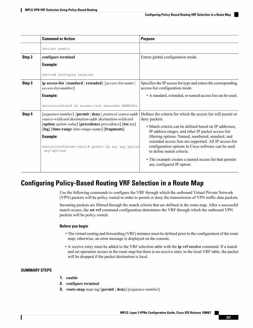
PurposeCommand or Action
Device> enable
Enters global configuration mode.configure terminal
Example:
Step 2
Device# configure terminal
Specifies the IP access list type and enters the correspondingaccess-list configuration mode.
ip access-list {standard | extended} [access-list-name |access-list-number]
Step 3
Example: • A standard, extended, or named access list can be used.
Device(config)# ip access-list extended NAMEDACL
Defines the criteria for which the access list will permit ordeny packets.
[sequence-number] {permit | deny} protocol source-addrsource-wildcard destination-addr destination-wildcard
Step 4
[option option-value] [precedence precedence] [tos tos][log] [time-range time-range-name] [fragments] • Match criteria can be defined based on IP addresses,
IP address ranges, and other IP packet access-listExample: filtering options. Named, numbered, standard, and
extended access lists are supported. All IP access-listDevice(config-ext-nacl)# permit ip any any optionany-options
configuration options in Cisco software can be usedto define match criteria.
• The example creates a named access list that permitsany configured IP option.
Configuring Policy-Based Routing VRF Selection in a Route MapUse the following commands to configure the VRF through which the outbound Virtual Private Network(VPN) packets will be policy routed in order to permit or deny the transmission of VPN traffic data packets.
Incoming packets are filtered through the match criteria that are defined in the route map. After a successfulmatch occurs, the set vrf command configuration determines the VRF through which the outbound VPNpackets will be policy routed.
Before you begin
• The virtual routing and forwarding (VRF) instance must be defined prior to the configuration of the routemap; otherwise, an error message is displayed on the console.
• A receive entry must be added to the VRF selection table with the ip vrf receive command. If a matchand set operation occurs in the route map but there is no receive entry in the local VRF table, the packetwill be dropped if the packet destination is local.
SUMMARY STEPS
1. enable2. configure terminal3. route-map map-tag [permit | deny] [sequence-number]
MPLS: Layer 3 VPNs Configuration Guide, Cisco IOS Release 15M&T257
MPLS VPN VRF Selection Using Policy-Based RoutingConfiguring Policy-Based Routing VRF Selection in a Route Map

4. Do one of the following:
• match ip address {acl-number [acl-number ... | acl-name ...] | acl-name [acl-name ... | acl-number...]}
•• match length minimum-length maximum-length
5. set vrf vrf-name6. exit
DETAILED STEPS
PurposeCommand or Action
Enables privileged EXEC mode.enableStep 1
Example: • Enter your password if prompted.
Device> enable
Enters global configuration mode.configure terminal
Example:
Step 2
Device# configure terminal
Enters route map configuration mode.route-map map-tag [permit | deny] [sequence-number]Step 3
Example: Defines the conditions for redistributing routes from onerouting protocol into another, or enables policy routing.
Device(config)# route-map map1 permit 10
Distributes any routes that have a destination networknumber address that is permitted by a standard or extendedaccess list, and performs policy routing onmatched packets.
Do one of the following:Step 4
• match ip address {acl-number [acl-number ... |acl-name ...] | acl-name [acl-name ... | acl-number ...]}
• IP access lists are supported.•• match length minimum-length maximum-length • The example configures the route map to use standard
access list 1 to define match criteria.Example:
Device(config-route-map)# match ip address 1 or
Specifies the Layer 3 packet length in the IP header as amatch criterion in a class map.
Example:
Device(config-route-map)# match length 3 200 • The example configures the route map to matchpackets that are 3 to 200 bytes in size.
Defines which VRF to route VPN packets that aresuccessfully matched in the same route map sequence forpolicy-based routing (PBR) VRF selection.
set vrf vrf-name
Example:
Device(config-route-map)# set vrf map1
Step 5
• The example policy routes matched packets out to theVRF named map1.
MPLS: Layer 3 VPNs Configuration Guide, Cisco IOS Release 15M&T258
MPLS VPN VRF Selection Using Policy-Based RoutingConfiguring Policy-Based Routing VRF Selection in a Route Map

PurposeCommand or Action
Returns to global configuration mode.exit
Example:
Step 6
Device(config-route-map)# exit
Configuring Policy-Based Routing on the InterfaceUse the following commands to filter incoming Virtual Private Network (VPN) traffic data packets. Incomingpackets are filtered through the match criteria that are defined in the route map.
The route map is applied to the incoming interface. The route map is attached to the incoming interface withthe ip policy route-map global configuration command.
• The MPLS VPN VRF Selection Using Policy-Based Routing feature can coexist with the MPLS VPNVRF Selection Based on Source IP address feature on the same device, but the two features cannot beconfigured together on the same interface. This is designed behavior to prevent virtual routing andforwarding (VRF) table selection conflicts that could occur if these features were misconfigured together.An error message is displayed on the console if you attempt to configure the ip vrf select source andthe ip policy route-map commands on the same interface.
>
Note
SUMMARY STEPS
1. enable2. configure terminal3. interface type number [name-tag]4. ip policy route-map map-tag5. ip vrf receive vrf-name6. exit
DETAILED STEPS
PurposeCommand or Action
Enables privileged EXEC mode.enableStep 1
Example: • Enter your password if prompted.
Device> enable
Enters global configuration mode.configure terminal
Example:
Step 2
Device# configure terminal
MPLS: Layer 3 VPNs Configuration Guide, Cisco IOS Release 15M&T259
MPLS VPN VRF Selection Using Policy-Based RoutingConfiguring Policy-Based Routing on the Interface

PurposeCommand or Action
Configures an interface and enters interface configurationmode.
interface type number [name-tag]
Example:
Step 3
Device(config)# interface FastEthernet 0/1/0
Identifies a route map to use for policy routing on aninterface.
ip policy route-map map-tag
Example:
Step 4
• The configuration example attaches the route mapnamed map1 to the interface.Device(config-if)# ip policy route-map map1
Adds the IP addresses that are associated with an interfaceinto the VRF table.
ip vrf receive vrf-name
Example:
Step 5
• This command must be configured for each VRF thatwill be used for VRF selection.Device(config-if)# ip vrf receive VRF1
Exits interface configuration mode and enters globalconfiguration mode.
exit
Example:
Step 6
Device(config-if)# exit
Configuring IP VRF Receive on the InterfaceUse the following commands to insert the IP address of an interface as a connected route entry in a virtualrouting and forwarding (VRF) routing table. This will prevent dropped packets.
The source IP address must be added to the VRF selection table. VRF selection is a one-way (unidirectional)feature. It is applied to the incoming interface. If a match and set operation occurs in the route map but thereis no VRF receive entry in the local VRF table, the packet will be dropped if the packet destination is local.
SUMMARY STEPS
1. enable2. configure terminal3. interface type number [name-tag]4. ip policy route-map map-tag5. ip vrf receive vrf-name6. end
DETAILED STEPS
PurposeCommand or Action
Enables privileged EXEC mode.enableStep 1
Example: • Enter your password if prompted.
Device> enable
MPLS: Layer 3 VPNs Configuration Guide, Cisco IOS Release 15M&T260
MPLS VPN VRF Selection Using Policy-Based RoutingConfiguring IP VRF Receive on the Interface

PurposeCommand or Action
Enters global configuration mode.configure terminal
Example:
Step 2
Device# configure terminal
Configures an interface and enters interface configurationmode.
interface type number [name-tag]
Example:
Step 3
Device(config)# interface FastEthernet 0/1/0
Identifies a route map to use for policy routing on aninterface.
ip policy route-map map-tag
Example:
Step 4
• The configuration example attaches the route mapnamed map1 to the interface.Device(config-if)# ip policy route-map map1
Adds the IP addresses that are associated with an interfaceinto the VRF table.
ip vrf receive vrf-name
Example:
Step 5
• This command must be configured for each VRF thatwill be used for VRF selection.Device(config-if)# ip vrf receive VRF1
Returns to privileged EXEC mode.end
Example:
Step 6
Device(config-if)# end
VerifyingtheConfigurationof theMPLSVPNVRFSelectionUsingPolicy-BasedRouting
SUMMARY STEPS
1. enable2. show ip access-list [access-list-number | access-list-name]3. show route-map [map-name]4. show ip policy
DETAILED STEPS
PurposeCommand or Action
Enables privileged EXEC mode.enableStep 1
Example: • Enter your password if prompted.
Device> enable
Displays the contents of all current IP access lists.show ip access-list [access-list-number | access-list-name]Step 2
MPLS: Layer 3 VPNs Configuration Guide, Cisco IOS Release 15M&T261
MPLS VPN VRF Selection Using Policy-Based RoutingVerifying the Configuration of the MPLS VPN VRF Selection Using Policy-Based Routing

PurposeCommand or Action
Example: • This command is used to verify the match criteria thatare defined in the access list. Both named andnumbered access lists are supported.Device# show ip access-list
Displays all route maps configured or only the one specified.show route-map [map-name]Step 3
Example: • This command is used to verify match and set clauseswithin the route map.
Device# show route-map
Displays the route map used for policy routing.show ip policyStep 4
Example: • This command can be used to display the route mapand the associated interface.
Device# show ip policy
Configuration Examples for MPLS VPN VRF Selection UsingPolicy-Based Routing
Example: Defining Policy-Based Routing VRF Selection in an Access ListIn the following example, three standard access lists are created to define match criteria for three differentsubnets. Any packets received on the FastEthernet 0/1/0 interface will be policy routed through the policy-basedrouting (PBR) VRF selection route map to the virtual routing and forwarding (VRF) instancer that is matchedin the same route map sequence. If the source IP address of the packet is part of the 10.1.0.0/24 subnet, VRF1will be used for routing and forwarding.
access-list 40 permit 10.1.0.0 0.0.255.255access-list 50 permit 10.2.0.0 0.0.255.255access-list 60 permit 10.3.0.0 0.0.255.255route-map PBR-VRF-Selection permit 10match ip address 40set vrf VRF1!route-map PBR-VRF-Selection permit 20match ip address 50set vrf VRF2!route-map PBR-VRF-Selection permit 30match ip address 60set vrf VRF3!interface FastEthernet0/1/0ip address 10.1.0.0/24 255.255.255.252ip policy route-map PBR-VRF-Selectionip vrf receive VRF1ip vrf receive VRF2ip vrf receive VRF3
MPLS: Layer 3 VPNs Configuration Guide, Cisco IOS Release 15M&T262
MPLS VPN VRF Selection Using Policy-Based RoutingConfiguration Examples for MPLS VPN VRF Selection Using Policy-Based Routing

Examples: Verifying VRF Selection Using Policy-Based RoutingThe following verification examples show defined match criteria and route-map policy configuration.
Example: Verifying Match CriteriaTo verify the configuration of match criteria for policy-based routing (PBR) VRF selection, use the show ipaccess-list command.
The following show ip access-list command output displays three subnet ranges defined as match criteria inthree standard access lists:
Device# show ip access-list
Standard IP access list 4010 permit 10.1.0.0, wildcard bits 0.0.255.255
Standard IP access list 5010 permit 10.2.0.0, wildcard bits 0.0.255.255
Standard IP access list 6010 permit 10.3.0.0, wildcard bits 0.0.255.255
Example: Verifying Route-Map ConfigurationTo verify route-map configuration, use the show route-map command. The output displays the match criteriaand set action for each route-map sequence. The output also displays the number of packets and bytes thathave been policy routed per each route-map sequence.
Device# show route-map
route-map PBR-VRF-Selection, permit, sequence 10Match clauses:ip address (access-lists): 40
Set clauses:vrf VRF1
Policy routing matches: 0 packets, 0 bytesroute-map PBR-VRF-Selection, permit, sequence 20Match clauses:ip address (access-lists): 50
Set clauses:vrf VRF2
Policy routing matches: 0 packets, 0 bytesroute-map PBR-VRF-Selection, permit, sequence 30Match clauses:ip address (access-lists): 60
Set clauses:vrf VRF3
Policy routing matches: 0 packets, 0 bytes
Example: Verifying Policy-Based Routing VRF Selection PolicyThe following show ip policy command output displays the interface and associated routemap that is configuredfor policy routing:
Device# show ip policy
Interface Route mapFastEthernet0/1/0 PBR-VRF-Selection
MPLS: Layer 3 VPNs Configuration Guide, Cisco IOS Release 15M&T263
MPLS VPN VRF Selection Using Policy-Based RoutingExamples: Verifying VRF Selection Using Policy-Based Routing

Additional ReferencesRelated Documents
Document TitleRelated Topic
Cisco Master Command List, All ReleasesCisco IOS commands
Cisco IOSMultiprotocol Label Switching Command ReferenceMPLS and MPLS applications commands
Technical Assistance
LinkDescription
http://www.cisco.com/cisco/web/support/index.htmlTheCisco Support andDocumentationwebsite providesonline resources to download documentation, software,and tools. Use these resources to install and configurethe software and to troubleshoot and resolve technicalissues with Cisco products and technologies. Access tomost tools on the Cisco Support and Documentationwebsite requires a Cisco.com user ID and password.
Feature Information for MPLS VPN VRF Selection UsingPolicy-Based Routing
The following table provides release information about the feature or features described in this module. Thistable lists only the software release that introduced support for a given feature in a given software releasetrain. Unless noted otherwise, subsequent releases of that software release train also support that feature.
Use Cisco Feature Navigator to find information about platform support and Cisco software image support.To access Cisco Feature Navigator, go to www.cisco.com/go/cfn. An account on Cisco.com is not required.
MPLS: Layer 3 VPNs Configuration Guide, Cisco IOS Release 15M&T264
MPLS VPN VRF Selection Using Policy-Based RoutingAdditional References
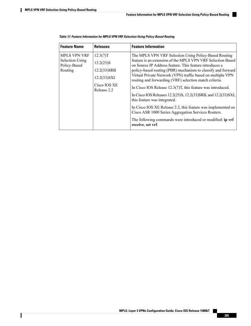
Table 17: Feature Information for MPLS VPN VRF Selection Using Policy-Based Routing
Feature InformationReleasesFeature Name
The MPLS VPN VRF Selection Using Policy-Based Routingfeature is an extension of the MPLS VPN VRF Selection Basedon Source IP Address feature. This feature introduces apolicy-based routing (PBR) mechanism to classify and forwardVirtual Private Network (VPN) traffic based on multiple VPNrouting and forwarding (VRF) selection match criteria.
In Cisco IOS Release 12.3(7)T, this feature was introduced.
In Cisco IOSReleases 12.2(25)S, 12.2(33)SRB, and 12.2(33)SXI,this feature was integrated.
In Cisco IOS XE Release 2.2, this feature was implemented onCisco ASR 1000 Series Aggregation Services Routers.
The following commands were introduced or modified: ip vrfreceive, set vrf.
12.3(7)T
12.2(25)S
12.2(33)SRB
12.2(33)SXI
Cisco IOS XERelease 2.2
MPLS VPN VRFSelection UsingPolicy-BasedRouting
MPLS: Layer 3 VPNs Configuration Guide, Cisco IOS Release 15M&T265
MPLS VPN VRF Selection Using Policy-Based RoutingFeature Information for MPLS VPN VRF Selection Using Policy-Based Routing

MPLS: Layer 3 VPNs Configuration Guide, Cisco IOS Release 15M&T266
MPLS VPN VRF Selection Using Policy-Based RoutingFeature Information for MPLS VPN VRF Selection Using Policy-Based Routing

C H A P T E R 17MPLS VPN BGP Local Convergence
This document provides information about reducing the downtime of a provider edge (PE) to customer edge(CE) link failure. It describes how to reroute PE-egress traffic onto a backup path to the CE before the BorderGateway Protocol (BGP) has reconverged. The MPLS VPN BGP Local Convergence feature is also referredto as “local protection.” This document explains how to use PE-CE local convergence.
The MPLS VPN BGP Local Convergence feature affects only traffic exiting the Virtual Private Network(VPN). Therefore, it cannot fully protect traffic end-to-end by itself.
Note
• Finding Feature Information, on page 267• Prerequisites for MPLS VPN BGP Local Convergence, on page 267• Restrictions for MPLS VPN BGP Local Convergence, on page 268• Information About MPLS VPN BGP Local Convergence, on page 269• How to Configure MPLS VPN BGP Local Convergence, on page 271• Configuration Examples for MPLS VPN BGP Local Convergence, on page 274• Additional References, on page 281• Feature Information for MPLS VPN BGP Local Convergence, on page 282
Finding Feature InformationYour software release may not support all the features documented in this module. For the latest caveats andfeature information, see Bug Search Tool and the release notes for your platform and software release. Tofind information about the features documented in this module, and to see a list of the releases in which eachfeature is supported, see the feature information table.
Use Cisco Feature Navigator to find information about platform support and Cisco software image support.To access Cisco Feature Navigator, go to www.cisco.com/go/cfn. An account on Cisco.com is not required.
Prerequisites for MPLS VPN BGP Local Convergence• Before MPLS VPN BGP Local Convergence link protection can be enabled, the customer site must beconnected to the provider site by more than one path.
MPLS: Layer 3 VPNs Configuration Guide, Cisco IOS Release 15M&T267

• Both the main forwarding path and the redundant backup path must have been installed within BorderGateway Protocol (BGP), and BGP must support lossless switchover between operational paths.
• Any of the supported routing protocols can be used between the provider edge (PE) and customer edge(CE) as long as the path is redistributed into BGP. The supported protocols for IPv4 are External BGP(eBGP), Routing Information Protocol (RIP), Enhanced Interior Gateway Routing Protocol (EIGRP),Open Shortest Path First (OSPF), and static routing. The supported protocols for IPv6 are eBGP andstatic routing.
• All PE devices that are serving as backup to the link must have assigned a unique route distinguisher toeach virtual routing and forwarding (VRF) table involved with the link to ensure that the route reflectorsadvertise all available paths.
• Although not required the backup PE (shown as “PE2” in the figure below) should run the same Ciscosoftware release that is running on the PE (“PE 1”) whose link with the CE is protected.
Restrictions for MPLS VPN BGP Local Convergence• The MPLS VPN BGP Local Convergence feature affects only traffic exiting the Virtual Private Network(VPN). Therefore, it cannot fully protect traffic end-to-end by itself.
• This link protection cannot be initiated during a high availability (HA) stateful switchover (SSO). Butlinks already configured with this protection before the switchover begins will remain protected afterthe switchover.
• If you perform an in-service software downgrade from an image that does include this link protection toan image that does not support this feature, active protection will be halted when Border Gateway Protocol(BGP) routes are refreshed.
• Any next-hop core tunneling technology that is supported by BGP is also supported for protection,including Multiprotocol Label Switching (MPLS), IP/Layer 2 Tunneling Protocol version 3 (L2TPv3),and IP/generic routing encapsulation (GRE). Enabling a Carrier Supporting Carrier (CSC) protocolbetween the provider edge (PE) and customer edge (CE) is also supported. Interautonomous systemoption A (back-to-back VRF) is supported because it is essentially the same as performing the PE-CElink protection in both autonomous systems. However, interautonomous system options B and C protectionare not supported.
• The MPLS VPN BGP Local Convergence feature for IPv4 supports the External BGP (eBGP), RoutingInformation Protocol (RIP), Enhanced Interior Gateway Routing Protocol (EIGRP), Open Shortest PathFirst (OSPF), and static routing protocols only.
• TheMPLSVPNBGP Local Convergence feature for IPv6 supports the eBGP and static routing protocolsonly.
MPLS: Layer 3 VPNs Configuration Guide, Cisco IOS Release 15M&T268
MPLS VPN BGP Local ConvergenceRestrictions for MPLS VPN BGP Local Convergence

Information About MPLS VPN BGP Local Convergence
How Link Failures Are Handled with BGPWithin a Layer 3 Virtual Private Network (VPN) network, the failure of a provider edge (PE)-customer edge(CE) link can cause a loss of connectivity (LoC) to a customer site, which is detrimental to time-sensitiveapplications. Several factors contribute to the duration of such an outage:
• The time to detect the failure
• The programming of the forwarding
• The convergence of the Border Gateway Protocol (BGP) (in large networks, the restored traffic arrivaltime at its destination varies according to the prefix)
When BGP detects a PE-CE link failure, it removes all of the BGP paths through the failing link. BGP runsthe best-path algorithm on the affected prefixes and selects alternate paths for each prefix. These new paths(which typically include a remote PE) are installed into forwarding. The local labels are removed and BGPwithdrawals are sent to all BGP neighbors. As each BGP neighbor receives the withdrawal messages (typicallyindirectly using route reflectors), the best-path algorithm is called and the prefixes are switched to an alternatepath. Only then is connectivity restored.
How Links Are Handled with the MPLS VPN BGP Local Convergence FeatureTheMPLS VPN BGP Local Convergence feature requires that the prefixes to be protected on a provider edge(PE)-customer edge (CE) link have at least one backup path that does not include that link. (See the figurebelow.) The customer site must have backup paths to the provider site.Figure 17: Network Configured with Primary and Backup Paths
The MPLS VPN BGP Local Convergence feature reduces loss of connectivity time by sending the brokenlink’s traffic over a backup path (as shown in the figure below) instead of waiting for total network convergence.The local label is maintained for 5 minutes while prefixes switch from the failing local path to the backuppath. Because the label is not freed as had been the usual practice, forwarding continues to take place.
MPLS: Layer 3 VPNs Configuration Guide, Cisco IOS Release 15M&T269
MPLS VPN BGP Local ConvergenceInformation About MPLS VPN BGP Local Convergence

The best-path algorithm selects the backup path. Thus, the local label has been applied in place of the failedBorder Gateway Protocol (BGP) best-path label (which is sometimes called “label swapping”). Traffic isrestored locally while the network propagation of the BGP withdrawal messages takes place. Eventually, theegress PE device converges and bypasses the local repair.Figure 18: Network Using the Backup Path After a PE-CE Link Failure on the Primary Path
After the 5-minute label preservation, the local labels are freed. Any BGP prefix that is remote and is not partof a Carrier Supporting Carrier (CSC) network does not have a local label and is removed. The delay in locallabel deletion does not modify normal BGP addition and deletion of BGP paths. Rather, BGP reprograms thenew backup best path into forwarding as usual.
Note
How Link Failures Are DetectedLocal protection relies on the Border Gateway Protocol (BGP) being notified of the interface failure. Detectioncan occur using either the interface drivers or the routing tables. If an interface or route goes down, thecorresponding path in the routing table is removed and BGP will be notified using the routing applicationprogramming interfaces (APIs).
However, when the routing table cannot detect the failure (as when a Layer 2 switch goes down), BGPdetermines that a neighbor is down through use of its hold-down timer. However, that determination can beextremely slow because of the 3-minute default for BGP session timeout.
You can reduce the detection delay by either reducing the BGP session timeout interval (as described in theConfiguring Internal BGP Features document) or by enabling the Bidirectional Forwarding Detection (BFD)protocol within External BGP (eBGP) between the provider edge (PE) and customer edge (CE).
MPLS: Layer 3 VPNs Configuration Guide, Cisco IOS Release 15M&T270
MPLS VPN BGP Local ConvergenceHow Link Failures Are Detected

How to Configure MPLS VPN BGP Local Convergence
To configure a VPN routing and forwarding (VRF) instance for IPv4 and IPv6 VPNs or to upgrade yourexisting single-protocol IPv4-only VRF to a multiprotocol VRF configuration, see the “MPLS VPN--VRFCLI for IPv4 and IPv6 VPNs” module.
Note
Configuring MPLS VPN BGP Local Convergence with IPv4
Before you begin
Ensure that the customer edge (CE) device is already connected to the provider edge (PE) device by a minimumof two paths.
SUMMARY STEPS
1. enable2. configure terminal3. ip vrf vrf-name4. rd route-distinguisher5. protection local-prefixes6. do show ip vrf detail
DETAILED STEPS
PurposeCommand or Action
Enables privileged EXEC mode.enableStep 1
Example: • Enter your password if prompted.
Device> enable
Enters global configuration mode.configure terminal
Example:
Step 2
Device# configure terminal
Enters VRF configuration mode.ip vrf vrf-nameStep 3
Example: • If no VRF routing table and Cisco Express Forwardingtable had been previously created for this named VRF,
Device(config)# ip vrf vpn1 then this command also creates them, giving bothtables the specified value for the vrf-name argument(in this example, the name is vpn1).
MPLS: Layer 3 VPNs Configuration Guide, Cisco IOS Release 15M&T271
MPLS VPN BGP Local ConvergenceHow to Configure MPLS VPN BGP Local Convergence

PurposeCommand or Action
(Optional) Establishes the route distinguisher for the namedVRF.
rd route-distinguisher
Example:
Step 4
• If no route distinguisher had been previouslyestablished for the named VRF, then you must enterthis command.
Device(config-vrf)# rd 100:3
• The route distinguisher value can be either an:
• Autonomous system number followed by a colonand an arbitrary number (for example, 100:3)
or
• • IP address followed by a colon and an arbitrarynumber (for example, 192.168.122.15:1)
Allows a preconfigured backup path to carry traffic if thePE-CE link breaks by preserving the local prefixes whileBGP reconverges.
protection local-prefixes
Example:
Device(config-vrf)# protection local-prefixes
Step 5
(Optional) Verifies that the MPLS VPN BGP LocalConvergence feature has been configured.
do show ip vrf detail
Example:
Step 6
Device(config-vrf)# do show ip vrf detail
Configuring MPLS VPNBGP Local Convergence with IPv6
Before you begin
Ensure that the customer edge (CE) device is already connected to the provider edge (PE) device by a minimumof two paths.
SUMMARY STEPS
1. enable2. configure terminal3. vrf definition vrf-name4. rd route-distinguisher5. address-family [ipv4 | ipv6]6. protection local-prefixes7. do show ip vrf detail
DETAILED STEPS
PurposeCommand or Action
Enables privileged EXEC mode.enableStep 1
MPLS: Layer 3 VPNs Configuration Guide, Cisco IOS Release 15M&T272
MPLS VPN BGP Local ConvergenceConfiguring MPLS VPNBGP Local Convergence with IPv6
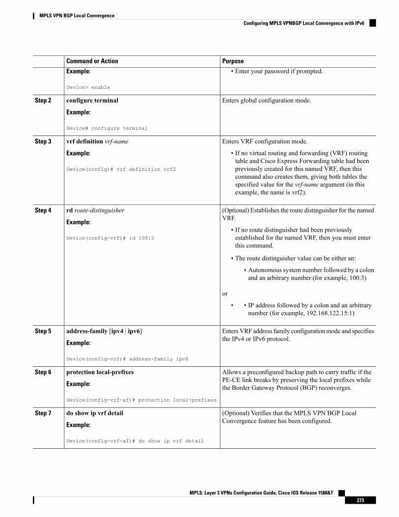
PurposeCommand or Action
Example: • Enter your password if prompted.
Device> enable
Enters global configuration mode.configure terminal
Example:
Step 2
Device# configure terminal
Enters VRF configuration mode.vrf definition vrf-nameStep 3
Example: • If no virtual routing and forwarding (VRF) routingtable and Cisco Express Forwarding table had been
Device(config)# vrf definition vrf2 previously created for this named VRF, then thiscommand also creates them, giving both tables thespecified value for the vrf-name argument (in thisexample, the name is vrf2).
(Optional) Establishes the route distinguisher for the namedVRF.
rd route-distinguisher
Example:
Step 4
• If no route distinguisher had been previouslyestablished for the named VRF, then you must enterthis command.
Device(config-vrf)# rd 100:3
• The route distinguisher value can be either an:
• Autonomous system number followed by a colonand an arbitrary number (for example, 100:3)
or
• • IP address followed by a colon and an arbitrarynumber (for example, 192.168.122.15:1)
Enters VRF address family configurationmode and specifiesthe IPv4 or IPv6 protocol.
address-family [ipv4 | ipv6]
Example:
Step 5
Device(config-vrf)# address-family ipv6
Allows a preconfigured backup path to carry traffic if thePE-CE link breaks by preserving the local prefixes whilethe Border Gateway Protocol (BGP) reconverges.
protection local-prefixes
Example:
Device(config-vrf-af)# protection local-prefixes
Step 6
(Optional) Verifies that the MPLS VPN BGP LocalConvergence feature has been configured.
do show ip vrf detail
Example:
Step 7
Device(config-vrf-af)# do show ip vrf detail
MPLS: Layer 3 VPNs Configuration Guide, Cisco IOS Release 15M&T273
MPLS VPN BGP Local ConvergenceConfiguring MPLS VPNBGP Local Convergence with IPv6

ExamplesTo verify that local link protection has been enabled, enter the show ip vrf detail command. If the protectionis enabled, the status message “Local prefix protection enabled” will be shown in the display:
Device# show ip vrf detail
VRF vpn1 (VRF Id = 1); default RD 100:1; default VPNID <not set>Interfaces:
AT1/0/1.1VRF Table ID = 1Export VPN route-target communitiesRT:100:1
Import VPN route-target communitiesRT:100:1 RT:100:2
No import route-mapNo export route-mapVRF label distribution protocol: not configuredVRF label allocation mode: per-prefix
Local prefix protection enabled
Troubleshooting Tips• Ensure that a minimum of two paths are present for the protected prefix in the Border Gateway Protocol(BGP) in steady state condition on the provider edge (PE) device. The path using the protected PE shouldbe the BGP best-path before failover occurs. To display the configuration, enter the show ip bgp vpnv4vrf vpn ip-prefix command.
• Ensure that local protection has been enabled in the protected PE by entering the show ip vrf detailcommand.
• When route reflectors exist in the topology, ensure that each virtual routing and forwarding (VRF) instancehas a unique route distinguisher.
Configuration Examples for MPLS VPN BGP Local Convergence
Examples: MPLS VPN BGP Local ConvergenceThe following examples show how MPLS VPN BGP local convergence can prevent traffic loss after a linkfailure. You can display a detailed view of local link protection before, during, and after the Border GatewayProtocol (BGP) convergence by using the show bgp vpnv4 and showmpls forwarding-table vrf commandsas shown in the following three-stage example.
The show bgp vpnv4 unicast command is equivalent to the show ip bgp vpnv4 command.Note
Example 1: Before the Link Failure
Both a primary path and a backup path have been configured:
MPLS: Layer 3 VPNs Configuration Guide, Cisco IOS Release 15M&T274
MPLS VPN BGP Local ConvergenceExamples

Device# show bgp vpnv4 unicast all 172.16.0.1BGP routing table entry for 100:1:172.16.0.1/32, version 2Paths: (2 available, best #2, table v1)Flag: 0x820Advertised to update-groups:
1100, imported path from 100:2:172.16.0.1/32172.16.0.6 (metric 21) from 172.16.0.7 (172.16.0.7)Origin incomplete, metric 0, localpref 100, valid, internalExtended Community: RT:100:0Originator: 172.16.0.6, Cluster list: 172.16.0.7mpls labels in/out 16/17
100172.16.1.1 from 172.16.1.1 (172.16.0.1)Origin incomplete, metric 0, localpref 100, valid, external, bestExtended Community: RT:100:0mpls labels in/out 16/nolabel
BGP routing table entry for 100:2:172.16.0.1/32, version 9Paths: (1 available, best #1, no table)Flag: 0x820Not advertised to any peer100172.16.0.6 (metric 21) from 172.16.0.7 (172.16.0.7)Origin incomplete, metric 0, localpref 100, valid, internal, bestExtended Community: RT:100:0Originator: 172.16.0.6, Cluster list: 172.16.0.7mpls labels in/out nolabel/17
Label information for both paths can be displayed:
Device# show bgp vpnv4 unicast all labelsNetwork Next Hop In label/Out labelRoute Distinguisher: 100:1 (v1)
172.16.0.1/32 172.16.0.6 16/17172.16.1.1 16/nolabel
172.16.0.5/32 172.16.0.4 nolabel/23172.16.0.22/32 0.0.0.0 17/nolabel(v1)172.16.0.44/32 172.16.0.4 nolabel/24172.16.0.66/32 172.16.0.6 nolabel/21172.16.1.0/24 172.16.1.1 18/nolabel
0.0.0.0 18/nolabel(v1)172.16.5.0/24 172.16.0.4 nolabel/25172.16.8.0/24 172.16.0.6 19/23
172.16.1.1 19/nolabelRoute Distinguisher: 100:2
172.16.0.1/32 172.16.0.6 nolabel/17172.16.0.66/32 172.16.0.6 nolabel/21172.16.8.0/24 172.16.0.6 nolabel/23
The PE1 (see the first figure above) forwarding table contains BGP best-path information:
Device# show mpls forwarding-table vrf v1 172.16.0.1 detailLocal Outgoing Prefix Bytes Label Outgoing Next HopLabel Label or Tunnel Id Switched interface16 No Label 172.16.0.1/32[V] 570 Et0/0 172.16.1.1
MAC/Encaps=14/14, MRU=1504, Label Stack{}AABBCC000B00AABBCC000C000800VPN route: v1No output feature configured
MPLS: Layer 3 VPNs Configuration Guide, Cisco IOS Release 15M&T275
MPLS VPN BGP Local ConvergenceExamples: MPLS VPN BGP Local Convergence

Example 2: After the Link Failure and Before BGP Convergence
After the link failure on only one path, the backup path remains available (see the second figure above):
Device# show bgp vpnv4 unicast all 172.16.0.1
BGP routing table entry for 100:1:172.16.0.1/32, version 19Paths: (1 available, best #1, table v1)Not advertised to any peer100, imported path from 100:2:172.16.0.1/32172.16.0.6 (metric 21) from 172.16.0.7 (172.16.0.7)Origin incomplete, metric 0, localpref 100, valid, internal, bestExtended Community: RT:100:0Originator: 172.16.0.6, Cluster list: 172.16.0.7mpls labels in/out 16/17
BGP routing table entry for 100:2:172.16.0.1/32, version 9Paths: (1 available, best #1, no table)Not advertised to any peer100172.16.0.6 (metric 21) from 172.16.0.7 (172.16.0.7)Origin incomplete, metric 0, localpref 100, valid, internal, bestExtended Community: RT:100:0Originator: 172.16.0.6, Cluster list: 172.16.0.7mpls labels in/out nolabel/17
The label information for the backup path label can be displayed:
Device# show bgp vpnv4 unicast all labels
Network Next Hop In label/Out labelRoute Distinguisher: 100:1 (v1)
172.16.0.1/32 172.16.0.6 16/17172.16.0.5/32 172.16.0.4 nolabel/23172.16.0.22/32 0.0.0.0 17/nolabel(v1)172.16.0.44/32 172.16.0.4 nolabel/24172.16.0.66/32 172.16.0.6 nolabel/21172.16.1.0/24 172.16.0.6 nolabel/22172.16.5.0/24 172.16.0.4 nolabel/25172.16.8.0/24 172.16.0.6 19/23
Route Distinguisher: 100:2172.16.0.1/32 172.16.0.6 nolabel/17172.16.0.66/32 172.16.0.6 nolabel/21172.16.1.0/24 172.16.0.6 nolabel/22172.16.8.0/24 172.16.0.6 nolabel/23
The PE 1 (see the first figure above) forwarding table contains new label and next-hop information to directtraffic onto the backup path:
Device# show mpls forwarding-table vrf v1 172.16.0.1 detail
Local Outgoing Prefix Bytes Label Outgoing Next HopLabel Label or Tunnel Id Switched interface16 17 172.16.0.1/32[V] 0 Et1/0 172.16.3.2
MAC/Encaps=14/22, MRU=1496, Label Stack{21 17}AABBCC000D00AABBCC000C018847 0001500000011000VPN route: v1No output feature configured
MPLS: Layer 3 VPNs Configuration Guide, Cisco IOS Release 15M&T276
MPLS VPN BGP Local ConvergenceExamples: MPLS VPN BGP Local Convergence

Example 3: After Local Label Expiration and BGP Reconvergence
Because the local label preservation window has expired, the replacement local label is now gone from thePE 1 forwarding table information:
Device# show mpls forwarding-table vrf v1 172.16.0.1 detailLocal Outgoing Prefix Bytes Label Outgoing Next HopLabel Label or Tunnel Id Switched interfaceNone 17 172.16.0.1/32[V] 0 Et1/0 172.16.3.2
MAC/Encaps=14/22, MRU=1496, Label Stack{21 17}AABBCC000D00AABBCC000C018847 0001500000011000VPN route: v1No output feature configured
The new BGP information reverts to the configuration shown in the first figure above:
Device# show bgp vpnv4 unicast all 172.16.0.1BGP routing table entry for 100:1:172.16.0.1/32, version 23Paths: (1 available, best #1, table v1)Not advertised to any peer100, imported path from 100:2:172.16.0.1/32172.16.0.6 (metric 21) from 172.16.0.7 (172.16.0.7)Origin incomplete, metric 0, localpref 100, valid, internal, bestExtended Community: RT:100:0Originator: 172.16.0.6, Cluster list: 172.16.0.7mpls labels in/out nolabel/17
BGP routing table entry for 100:2:172.16.0.1/32, version 9Paths: (1 available, best #1, no table)Not advertised to any peer100172.16.0.6 (metric 21) from 172.16.0.7 (172.16.0.7)Origin incomplete, metric 0, localpref 100, valid, internal, bestExtended Community: RT:100:0Originator: 172.16.0.6, Cluster list: 172.16.0.7mpls labels in/out nolabel/17
Device# show bgp vpnv4 unicast all labels
Network Next Hop In label/Out labelRoute Distinguisher: 100:1 (v1)
172.16.0.1/32 172.16.0.6 nolabel/17172.16.0.5/32 172.16.0.4 nolabel/23172.16.0.22/32 0.0.0.0 17/nolabel(v1)172.16.0.44/32 172.16.0.4 nolabel/24172.16.0.66/32 172.16.0.6 nolabel/21172.16.1.0/24 172.16.0.6 nolabel/22172.16.5.0/24 172.16.0.4 nolabel/25172.16.8.0/24 172.16.0.6 nolabel/23
Route Distinguisher: 100:2172.16.0.1/32 172.16.0.6 nolabel/17172.16.0.66/32 172.16.0.6 nolabel/21172.16.1.0/24 172.16.0.6 nolabel/22172.16.8.0/24 172.16.0.6 nolabel/23
Examples: MPLS VPN BGP Local Convergence for 6VPE 6PEYou can display a detailed view of local link protection before, during, and after the Border Gateway Protocol(BGP) local convergence for Cisco VPN IPv6 provider edge devices (6VPE) and Cisco IPv6 provider edgedevices (6PE) over Multiprotocol Label Switching (MPLS) by using the show bgp vpnv6 and show mplsforwarding-table vrf commands as shown in the following three-stage example.
MPLS: Layer 3 VPNs Configuration Guide, Cisco IOS Release 15M&T277
MPLS VPN BGP Local ConvergenceExamples: MPLS VPN BGP Local Convergence for 6VPE 6PE

The figure below shows an MPLS VPN with BGP local convergence configured. The PE-to-CE routingprotocol is External BGP (eBGP), and the PE to route reflector (RR) sessions are BGP VPNv6. The protectedprefix is the CE 1 loopback (2001:0DB8::/128). The primary path is from PE 1 to CE 1. The secondary pathis from PE 1, through P and PE3, to CE 1.
MPLS: Layer 3 VPNs Configuration Guide, Cisco IOS Release 15M&T278
MPLS VPN BGP Local ConvergenceExamples: MPLS VPN BGP Local Convergence for 6VPE 6PE

Figure 19: MPLS VPN BGP Local Convergence
MPLS: Layer 3 VPNs Configuration Guide, Cisco IOS Release 15M&T279
MPLS VPN BGP Local ConvergenceExamples: MPLS VPN BGP Local Convergence for 6VPE 6PE

Example 1: Before the Link Failure
Both a primary path and a backup path have been configured for the prefix 2001:0DB8::/128. Theinlabel/outlabel settings for the two paths are 28/28 and 28/nolabel.
Device# show bgp vpnv6 unicast all 2001:0DB8::/128BGP routing table entry for [1:1]2001:0DB8::/128, version 5Paths: (2 available, best #2, table v1)Advertised to update-groups:
2100, imported path from [2:2]2001:0DB8::/128::FFFF:10.6.6.6 (metric 21) from 10.7.7.7 (10.7.7.7)Origin incomplete, metric 0, localpref 100, valid, internalExtended Community: RT:1:1Originator: 10.6.6.6, Cluster list: 10.7.7.7mpls labels in/out 28/28
1002001:0DB8:0:ABCD::1 (FE80::A8BB:CCFF:FE00:B00) from 2001:0DB8:0:ABCD::1 (10.1.1.1)Origin incomplete, metric 0, localpref 100, valid, external, best
Extended Community: RT:1:1mpls labels in/out 28/nolabel
BGP routing table entry for [2:2]2001:0DB8::/128, version 11Paths: (1 available, best #1, no table)Not advertised to any peer100::FFFF:10.6.6.6 (metric 21) from 10.7.7.7 (10.7.7.7)Origin incomplete, metric 0, localpref 100, valid, internal, bestExtended Community: RT:1:1Originator: 10.6.6.6, Cluster list: 10.7.7.7mpls labels in/out nolabel/28
The PE 1 forwarding table contains new label and next-hop information to direct traffic onto the backup path:
Device#show mpls forwarding-table vrf v1 2001:0DB8::/128 detailLocal Outgoing Prefix Bytes Label Outgoing Next HopLabel Label or Tunnel Id Switched interface28 No Label 2001:0DB8::/128[V] 804 Et0/0 FE80::A8BB:CCFF:FE00:B00
MAC/Encaps=14/14, MRU=1504, Label Stack{}AABBCC000B00AABBCC000C0086DDVPN route: v1No output feature configured
Example 2: After the Link Failure
After the link failure, the backup path is still available, the original path is removed from BGP, and the backuppath is activated:
Device# show mpls forwarding-table vrf v1 2001:0DB8::/128 detailLocal Outgoing Prefix Bytes Label Outgoing Next HopLabel Label or Tunnel Id Switched interface28 28 2001:0DB8::/128[V] 0 Et1/0 10.3.0.2
MAC/Encaps=14/22, MRU=1496, Label Stack{23 28}AABBCC000D00AABBCC000C018847 000170000001C000VPN route: v1No output feature configured
After a configured length of time, the local label expires. The output from the show mplsforwarding-tablecommand also verifies that the local label has expired:
MPLS: Layer 3 VPNs Configuration Guide, Cisco IOS Release 15M&T280
MPLS VPN BGP Local ConvergenceExamples: MPLS VPN BGP Local Convergence for 6VPE 6PE

Device# show mpls forwarding-table vrf v1 2001:0DB8::/128 detailLocal Outgoing Prefix Bytes Label Outgoing Next HopLabel Label or Tunnel Id Switched interfaceNone 28 2001:0DB8::/128[V] 0 Et1/0 10.3.0.2
MAC/Encaps=14/22, MRU=1496, Label Stack{23 28}AABBCC000D00AABBCC000C018847 000170000001C000VPN route: v1No output feature configured
Example 3: After the Link Is Restored
When the link is restored the original path is added to BGP and the traffic switches back to this path:
Device# show bgp vpnv6 unicast all 2001:0DB8::/128BGP routing table entry for [1:1]2001:0DB8::/128, version 28Paths: (2 available, best #1, table v1)Advertised to update-groups:
21002001:0DB8:0:ABCD::1 (FE80::A8BB:CCFF:FE00:B00) from 2001:0DB8:0:ABCD::1 (10.1.1.1)Origin incomplete, metric 0, localpref 100, valid, external, bestExtended Community: RT:1:1mpls labels in/out 16/nolabel
100, imported path from [2:2]2001:0DB8::/128::FFFF:10.6.6.6 (metric 21) from 10.7.7.7 (10.7.7.7)Origin incomplete, metric 0, localpref 100, valid, internalExtended Community: RT:1:1Originator: 10.6.6.6, Cluster list: 10.7.7.7mpls labels in/out 16/28
BGP routing table entry for [2:2]2001:0DB8::/128, version 11Paths: (1 available, best #1, no table)Not advertised to any peer100::FFFF:10.6.6.6 (metric 21) from 10.7.7.7 (10.7.7.7)Origin incomplete, metric 0, localpref 100, valid, internal, bestExtended Community: RT:1:1Originator: 10.6.6.6, Cluster list: 10.7.7.7mpls labels in/out nolabel/28
Device# show mpls for vrf v1 2001:0DB8::/128 detailLocal Outgoing Prefix Bytes Label Outgoing Next HopLabel Label or Tunnel Id Switched interface16 No Label 2001:0DB8::/128[V] 0 Et0/0 FE80::A8BB:CCFF:FE00:B00
MAC/Encaps=14/14, MRU=1504, Label Stack{}AABBCC000B00AABBCC000C0086DDVPN route: v1No output feature configured
Additional ReferencesRelated Documents
Document TitleRelated Topic
Cisco Master Command List, All ReleasesCisco IOS commands
Cisco IOS Multiprotocol Label Switching CommandReference
MPLS and MPLS applications commands
MPLS: Layer 3 VPNs Configuration Guide, Cisco IOS Release 15M&T281
MPLS VPN BGP Local ConvergenceAdditional References

Document TitleRelated Topic
“Configuring a Basic BGP Network” module in the IPRouting: BGP Configuration Guide
BGP configuration
“Bidirectional Forwarding Detection” module in the IPRouting: BFD Configuration Guide
Protocol for quickly detecting failedforwarding paths
“BGP PIC Edge for IP andMPLSVPN”module in theMPLSLayer 3 VPNs Configuration Guide
Configuration of BGP PIC Edge for IP andMPLS-VPN
“Configuring Internal BGP Features” module in the IPRouting: BGP Configuration Guide
Configuration of internal BGP features
“MPLS VPN VRF CLI for IPv4 and IPv6 VPNs” module intheMPLS Layer 3 VPNs Configuration Guide
Configuration of VRF under the specific casesof IPv4 and IPv6 situations
Standards and RFCs
TitleStandard/RFC
BGP/MPLSVPNsRFC 2547
Technical Assistance
LinkDescription
http://www.cisco.com/cisco/web/support/index.htmlTheCisco Support andDocumentationwebsite providesonline resources to download documentation, software,and tools. Use these resources to install and configurethe software and to troubleshoot and resolve technicalissues with Cisco products and technologies. Access tomost tools on the Cisco Support and Documentationwebsite requires a Cisco.com user ID and password.
Feature Information for MPLS VPN BGP Local ConvergenceThe following table provides release information about the feature or features described in this module. Thistable lists only the software release that introduced support for a given feature in a given software releasetrain. Unless noted otherwise, subsequent releases of that software release train also support that feature.
Use Cisco Feature Navigator to find information about platform support and Cisco software image support.To access Cisco Feature Navigator, go to www.cisco.com/go/cfn. An account on Cisco.com is not required.
MPLS: Layer 3 VPNs Configuration Guide, Cisco IOS Release 15M&T282
MPLS VPN BGP Local ConvergenceFeature Information for MPLS VPN BGP Local Convergence

Table 18: Feature Information for MPLS VPN BGP Local Convergence
Feature InformationReleasesFeature Name
The MPLS VPN BGP Local Convergence feature reduces thedowntime of a PE-CE link failure by rerouting PE-egress trafficonto a backup path to the CE before BGP has reconverged.
In 12.2(33)SRC, this feature was introduced on the Cisco 7200and the Cisco 7600.
In 12.2(33)SB, this feature became available on the Cisco 7300series and the Cisco 10000 Series Routers.
This feature was integrated into Cisco IOS Release 15.0(1)M.
In Cisco IOS XE Release 3.1S, this feature was implemented onCisco ASR 1000 Series Routers.
The following commandwasmodified:protection local-prefixes.
12.2(33)SRC
12.2(33)SB
15.0(1)M
Cisco IOS XERelease 3.1S
MPLS VPN BGPLocal Convergence
TheMPLSVPNBGP Local Convergence for 6VPE/6PE featureimplements MPLS VPN BGP local convergence for Cisco VPNIPv6 provider edge devices (6VPE) and Cisco IPv6 provider edgedevices (6PE) over MPLS.
In 15.0(1)S, this feature was introduced.
In Cisco IOS XE Release, 3.1S, this feature was implemented onCisco ASR 1000 Series Routers.
The following commandwasmodified:protection local-prefixes.
15.0(1)S
Cisco IOS XERelease 3.1S
MPLS VPN BGPLocal Convergencefor 6VPE/6PE
MPLS: Layer 3 VPNs Configuration Guide, Cisco IOS Release 15M&T283
MPLS VPN BGP Local ConvergenceFeature Information for MPLS VPN BGP Local Convergence

MPLS: Layer 3 VPNs Configuration Guide, Cisco IOS Release 15M&T284
MPLS VPN BGP Local ConvergenceFeature Information for MPLS VPN BGP Local Convergence

C H A P T E R 18Multi-VRF Support
The Multi-VRF Support feature allows you to configure and maintain more than one instance of a routingand forwarding table within the same customer edge (CE) device.
• Finding Feature Information, on page 285• Prerequisites for Multi-VRF Support, on page 285• Restrictions for Multi-VRF Support, on page 285• Information About Multi-VRF Support, on page 286• How to Configure Multi-VRF Support, on page 288• Configuration Examples for Multi-VRF Support, on page 296• Additional References, on page 298• Feature Information for Multi-VRF Support, on page 298
Finding Feature InformationYour software release may not support all the features documented in this module. For the latest caveats andfeature information, see Bug Search Tool and the release notes for your platform and software release. Tofind information about the features documented in this module, and to see a list of the releases in which eachfeature is supported, see the feature information table.
Use Cisco Feature Navigator to find information about platform support and Cisco software image support.To access Cisco Feature Navigator, go to www.cisco.com/go/cfn. An account on Cisco.com is not required.
Prerequisites for Multi-VRF SupportThe network’s core and provider edge (PE) devices must be configured for Virtual Private Network (VPN)operation.
Restrictions for Multi-VRF Support• You can configure the Multi-VRF Support feature only on Layer 3 interfaces.
• The Multi-VRF Support feature is not supported by Interior Gateway Routing Protocol (IGRP) norIntermediate System to Intermediate System (IS-IS).
MPLS: Layer 3 VPNs Configuration Guide, Cisco IOS Release 15M&T285
• Label distribution for a given VPN routing and forwarding (VRF) instance on a given device can behandled by either Border Gateway Protocol (BGP) or Label Distribution Protocol (LDP), but not by bothprotocols at the same time.
• Multicast cannot operate on a Layer 3 interface that is configured with the Multi-VRF Support feature.
Information About Multi-VRF Support
How the Multi-VRF Support Feature WorksThe Multi-VRF Support feature enables a service provider to support two or more Virtual Private Networks(VPNs), where the IP addresses can overlap several VPNs. TheMulti-VRF Support feature uses input interfacesto distinguish routes for different VPNs and forms virtual packet-forwarding tables by associating one or moreLayer 3 interfaces with each virtual routing and forwarding (VRF) instance. Interfaces in a VRF can be eitherphysical, such as FastEthernet ports, or logical, such as VLAN , but a Layer 3 interface cannot belong to morethan one VRF at any one time. The Multi-VRF Support feature allows an operator to support two or morerouting domains on a customer edge (CE) device, with each routing domain having its own set of interfacesand its own set of routing and forwarding tables. The Multi-VRF Support feature makes it possible to extendthe label switched paths (LSPs) to the CE and into each routing domain that the CE supports.
The Multi-VRF Support feature works as follows:
• Each CE device advertises its site’s local routes to a provider edge (PE) device and learns the remoteVPN routes from that provider edge (PE) device.
• PE devices exchange routing information with CE devices by using static routing or a routing protocolsuch as the Border Gateway Protocol (BGP), Routing Information Protocol version 1 (RIPv1), or RIPv2.
• PE devices exchange MPLS label information with CE devices through Label Distribution Protocol(LDP) or BGP.
• The PE device needs to maintain VPN routes only for those VPNs to which it is directly attached,eliminating the requirement that the PEmaintain all of the service provider’s VPN routes. Each PE devicemaintains a VRF for each of its directly connected sites. Two or more interfaces on a PE device can beassociated with a single VRF if all the sites participate in the same VPN. Each VPN is mapped to aspecified VRF. After learning local VPN routes from CE devices, the PE device exchanges VPN routinginformation with other PE devices through internal BGP (iBGP).
With the Multi-VRF Support feature, two or more customers can share one CE device, and only one physicallink is used between the CE and the PE devices. The shared CE device maintains separate VRF tables foreach customer and routes packets for each customer based on that customer’s own routing table. TheMulti-VRFSupport feature extends limited PE device functionality to a CE device, giving it the ability, through themaintenance of separate VRF tables, to extend the privacy and security of a VPN to the branch office.
The figure below shows a configuration where each CE device acts as if it were two CE devices. Because theMulti-VRF Support feature is a Layer 3 feature, each interface associated with a VRF must be a Layer 3interface.
MPLS: Layer 3 VPNs Configuration Guide, Cisco IOS Release 15M&T286
Multi-VRF SupportInformation About Multi-VRF Support
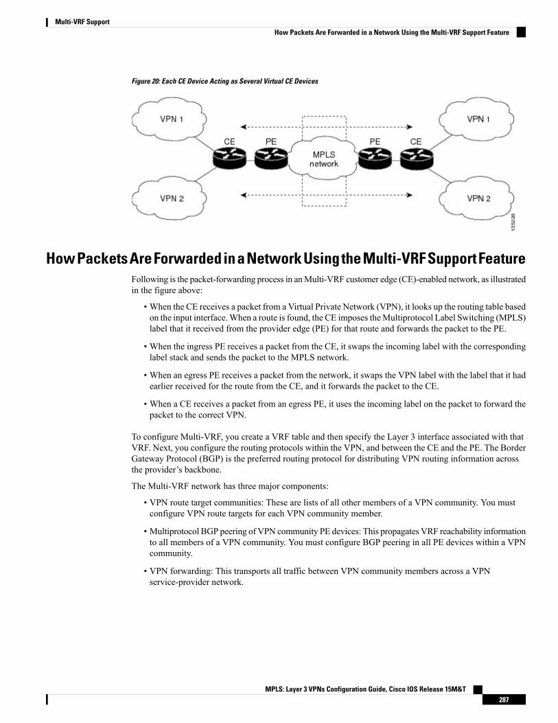
Figure 20: Each CE Device Acting as Several Virtual CE Devices
HowPacketsAreForwardedinaNetworkUsingtheMulti-VRFSupportFeatureFollowing is the packet-forwarding process in anMulti-VRF customer edge (CE)-enabled network, as illustratedin the figure above:
• When the CE receives a packet from a Virtual Private Network (VPN), it looks up the routing table basedon the input interface.When a route is found, the CE imposes theMultiprotocol Label Switching (MPLS)label that it received from the provider edge (PE) for that route and forwards the packet to the PE.
• When the ingress PE receives a packet from the CE, it swaps the incoming label with the correspondinglabel stack and sends the packet to the MPLS network.
• When an egress PE receives a packet from the network, it swaps the VPN label with the label that it hadearlier received for the route from the CE, and it forwards the packet to the CE.
• When a CE receives a packet from an egress PE, it uses the incoming label on the packet to forward thepacket to the correct VPN.
To configure Multi-VRF, you create a VRF table and then specify the Layer 3 interface associated with thatVRF. Next, you configure the routing protocols within the VPN, and between the CE and the PE. The BorderGateway Protocol (BGP) is the preferred routing protocol for distributing VPN routing information acrossthe provider’s backbone.
The Multi-VRF network has three major components:
• VPN route target communities: These are lists of all other members of a VPN community. You mustconfigure VPN route targets for each VPN community member.
• Multiprotocol BGP peering of VPN community PE devices: This propagates VRF reachability informationto all members of a VPN community. You must configure BGP peering in all PE devices within a VPNcommunity.
• VPN forwarding: This transports all traffic between VPN community members across a VPNservice-provider network.
MPLS: Layer 3 VPNs Configuration Guide, Cisco IOS Release 15M&T287
Multi-VRF SupportHow Packets Are Forwarded in a Network Using the Multi-VRF Support Feature
Considerations When Configuring the Multi-VRF Support Feature• A device with the Multi-VRF Support feature is shared by several customers, and each customer has itsown routing table.
• Because each customer uses a different virtual routing and forwarding (VRF) table, the same IP addressescan be reused. Overlapping IP addresses are allowed in different Virtual Private Networks (VPNs).
• TheMulti-VRF Support feature lets several customers share the same physical link between the provideredge (PE) and the customer edge (CE) devices. Trunk ports with several VLANs separate packets amongthe customers. Each customer has its own VLAN.
• For the PE device, there is no difference between using the Multi-VRF Support feature or using severalCE devices.
• The Multi-VRF Support feature does not affect the packet-switching rate.
How to Configure Multi-VRF Support
Configuring VRFsTo configure virtual routing and forwarding (VRF) instances, complete the following procedure. Be sure toconfigure VRFs on both the provider edge (PE) and customer edge (CE) devices.
If a VRF has not been configured, the device has the following default configuration:
• No VRFs have been defined.
• No import maps, export maps, or route maps have been defined.
• No VRF maximum routes exist.
• Only the global routing table exists on the interface.
The following are the supported flavors of multicast over VRF on Cisco ASR 920 RSP2 module:
• Multicast with multi-VRF (MPLS VPN/MLDP)
• Multicast with GRE tunnel (MVPN GRE)
• Multicast with VRF-lite
Multi-VRF/MVPN GRE configured layer-3 interface cannot participate in more than one VRF at the sametime.
Note
SUMMARY STEPS
1. enable2. configure terminal3. ip routing
MPLS: Layer 3 VPNs Configuration Guide, Cisco IOS Release 15M&T288
Multi-VRF SupportConsiderations When Configuring the Multi-VRF Support Feature
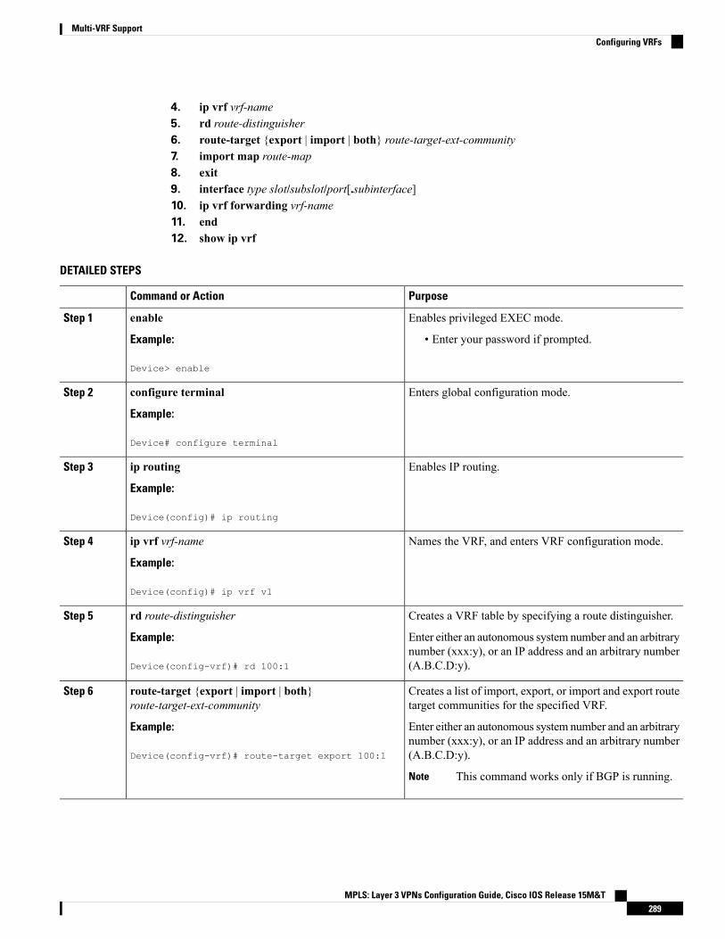
4. ip vrf vrf-name5. rd route-distinguisher6. route-target {export | import | both} route-target-ext-community7. import map route-map8. exit9. interface type slot/subslot/port[.subinterface]10. ip vrf forwarding vrf-name11. end12. show ip vrf
DETAILED STEPS
PurposeCommand or Action
Enables privileged EXEC mode.enableStep 1
Example: • Enter your password if prompted.
Device> enable
Enters global configuration mode.configure terminal
Example:
Step 2
Device# configure terminal
Enables IP routing.ip routing
Example:
Step 3
Device(config)# ip routing
Names the VRF, and enters VRF configuration mode.ip vrf vrf-name
Example:
Step 4
Device(config)# ip vrf v1
Creates a VRF table by specifying a route distinguisher.rd route-distinguisherStep 5
Example: Enter either an autonomous system number and an arbitrarynumber (xxx:y), or an IP address and an arbitrary number(A.B.C.D:y).Device(config-vrf)# rd 100:1
Creates a list of import, export, or import and export routetarget communities for the specified VRF.
route-target {export | import | both}route-target-ext-community
Step 6
Example: Enter either an autonomous system number and an arbitrarynumber (xxx:y), or an IP address and an arbitrary number(A.B.C.D:y).Device(config-vrf)# route-target export 100:1
This command works only if BGP is running.Note
MPLS: Layer 3 VPNs Configuration Guide, Cisco IOS Release 15M&T289
Multi-VRF SupportConfiguring VRFs
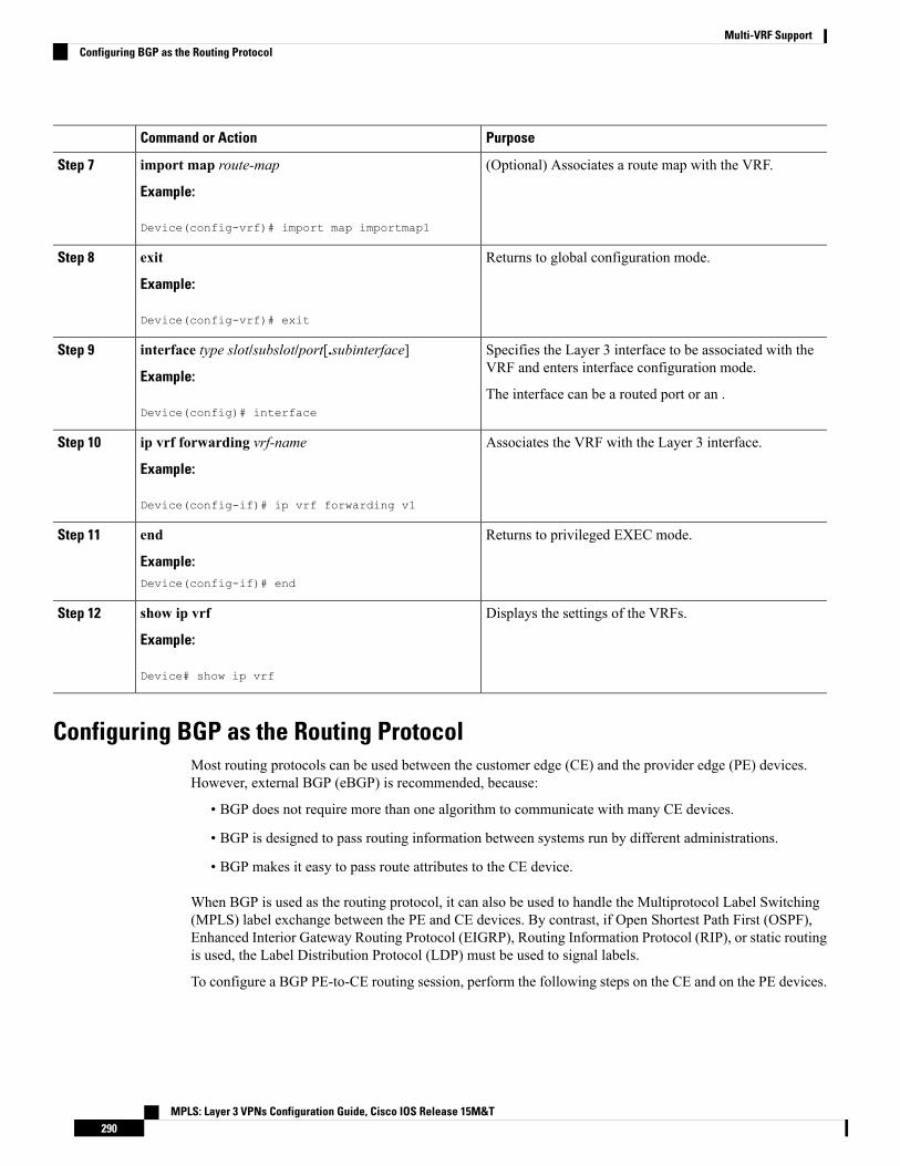
PurposeCommand or Action
(Optional) Associates a route map with the VRF.import map route-map
Example:
Step 7
Device(config-vrf)# import map importmap1
Returns to global configuration mode.exit
Example:
Step 8
Device(config-vrf)# exit
Specifies the Layer 3 interface to be associated with theVRF and enters interface configuration mode.
interface type slot/subslot/port[.subinterface]
Example:
Step 9
The interface can be a routed port or an .Device(config)# interface
Associates the VRF with the Layer 3 interface.ip vrf forwarding vrf-name
Example:
Step 10
Device(config-if)# ip vrf forwarding v1
Returns to privileged EXEC mode.end
Example:
Step 11
Device(config-if)# end
Displays the settings of the VRFs.show ip vrf
Example:
Step 12
Device# show ip vrf
Configuring BGP as the Routing ProtocolMost routing protocols can be used between the customer edge (CE) and the provider edge (PE) devices.However, external BGP (eBGP) is recommended, because:
• BGP does not require more than one algorithm to communicate with many CE devices.
• BGP is designed to pass routing information between systems run by different administrations.
• BGP makes it easy to pass route attributes to the CE device.
When BGP is used as the routing protocol, it can also be used to handle the Multiprotocol Label Switching(MPLS) label exchange between the PE and CE devices. By contrast, if Open Shortest Path First (OSPF),Enhanced Interior Gateway Routing Protocol (EIGRP), Routing Information Protocol (RIP), or static routingis used, the Label Distribution Protocol (LDP) must be used to signal labels.
To configure a BGP PE-to-CE routing session, perform the following steps on the CE and on the PE devices.
MPLS: Layer 3 VPNs Configuration Guide, Cisco IOS Release 15M&T290
Multi-VRF SupportConfiguring BGP as the Routing Protocol

SUMMARY STEPS
1. enable2. configure terminal3. router bgp autonomous-system-number4. network ip-addressmask network-mask5. redistribute ospf process-idmatch internal6. network ip-address wildcard-mask area area-id7. address-family ipv4 vrf vrf-name8. neighbor {ip-address | peer-group-name} remote-as as-number9. neighbor address activate
DETAILED STEPS
PurposeCommand or Action
Enables privileged EXEC mode.enableStep 1
Example: • Enter your password if prompted.
Device> enable
Enters global configuration mode.configure terminal
Example:
Step 2
Device# configure terminal
Configures the BGP routing process with the autonomoussystem number passed to other BGP devices, and entersrouter configuration mode.
router bgp autonomous-system-number
Example:
Device(config)# router bgp 100
Step 3
Specifies a network and mask to announce using BGP.network ip-addressmask network-mask
Example:
Step 4
Device(config-router)# network 10.0.0.0 mask255.255.255.0
Sets the device to redistribute OSPF internal routes.redistribute ospf process-idmatch internal
Example:
Step 5
Device(config-router)# redistribute ospf 2 matchinternal
Identifies the network address and mask on which OSPF isrunning, and the area ID of that network address.
network ip-address wildcard-mask area area-id
Example:
Step 6
Device(config-router)# network 10.0.0.0255.255.255.0 area 0
MPLS: Layer 3 VPNs Configuration Guide, Cisco IOS Release 15M&T291
Multi-VRF SupportConfiguring BGP as the Routing Protocol

PurposeCommand or Action
Identifies the name of the virtual routing and forwarding(VRF) instance that will be associated with the next twocommands, and enters VRF address-family mode.
address-family ipv4 vrf vrf-name
Example:
Device(config-router)# address-family ipv4 vrf v12
Step 7
Informs this device’s BGP neighbor table of the neighbor’saddress (or peer group name) and the neighbor’sautonomous system number.
neighbor {ip-address | peer-group-name} remote-asas-number
Example:
Step 8
Device(config-router-af)# neighbor 10.0.0.3remote-as 100
Activates the advertisement of the IPv4 address-familyneighbors.
neighbor address activate
Example:
Step 9
Device(config-router-af)# neighbor 10.0.0.3activate
Configuring PE-to-CE MPLS Forwarding and Signaling with BGPIf the Border Gateway Protocol (BGP) is used for routing between the provider edge (PE) and the customeredge (CE) devices, configure BGP to signal the labels on the virtual routing and forwarding (VRF) interfacesof both the CE and the PE devices. You must enable signalling globally at the router-configuration level andfor each interface:
• At the router-configuration level, to enable Multiprotocol Label Switching (MPLS) label signalling viaBGP, use the neighbor send-label command).
• At the interface level, to enable MPLS forwarding on the interface used for the PE-to-CE external BGP(eBGP) session, use thempls bgp forwarding command.
SUMMARY STEPS
1. enable2. configure terminal3. router bgp autonomous-system-number4. address-family ipv4 vrf vrf-name5. neighbor address send-label6. neighbor address activate7. end8. configure terminal9. interface type slot/subslot/port[.subinterface]10. mpls bgp forwarding
MPLS: Layer 3 VPNs Configuration Guide, Cisco IOS Release 15M&T292
Multi-VRF SupportConfiguring PE-to-CE MPLS Forwarding and Signaling with BGP
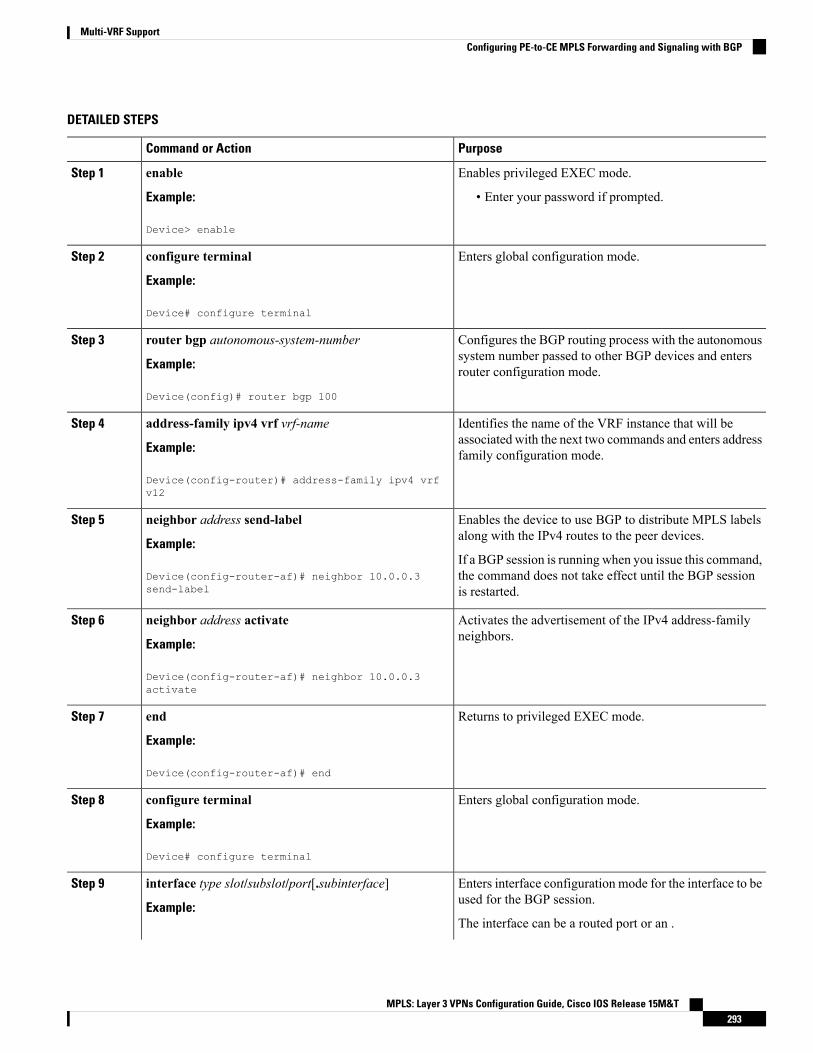
DETAILED STEPS
PurposeCommand or Action
Enables privileged EXEC mode.enableStep 1
Example: • Enter your password if prompted.
Device> enable
Enters global configuration mode.configure terminal
Example:
Step 2
Device# configure terminal
Configures the BGP routing process with the autonomoussystem number passed to other BGP devices and entersrouter configuration mode.
router bgp autonomous-system-number
Example:
Device(config)# router bgp 100
Step 3
Identifies the name of the VRF instance that will beassociated with the next two commands and enters addressfamily configuration mode.
address-family ipv4 vrf vrf-name
Example:
Device(config-router)# address-family ipv4 vrfv12
Step 4
Enables the device to use BGP to distribute MPLS labelsalong with the IPv4 routes to the peer devices.
neighbor address send-label
Example:
Step 5
If a BGP session is running when you issue this command,the command does not take effect until the BGP sessionis restarted.
Device(config-router-af)# neighbor 10.0.0.3send-label
Activates the advertisement of the IPv4 address-familyneighbors.
neighbor address activate
Example:
Step 6
Device(config-router-af)# neighbor 10.0.0.3activate
Returns to privileged EXEC mode.end
Example:
Step 7
Device(config-router-af)# end
Enters global configuration mode.configure terminal
Example:
Step 8
Device# configure terminal
Enters interface configuration mode for the interface to beused for the BGP session.
interface type slot/subslot/port[.subinterface]
Example:
Step 9
The interface can be a routed port or an .
MPLS: Layer 3 VPNs Configuration Guide, Cisco IOS Release 15M&T293
Multi-VRF SupportConfiguring PE-to-CE MPLS Forwarding and Signaling with BGP

PurposeCommand or Action
Device(config)# interface
Enables MPLS forwarding on the interface.mpls bgp forwarding
Example:
Step 10
Device(config-if)# mpls bgp forwarding
Configuring a Routing Protocol Other than BGPYou can use the Routing Information Protocol (RIP), Enhanced Interior Gateway Routing Protocol (EIGRP),Open Shortest Path First (OSPF), or static routing. This configuration uses OSPF, but the process is the samefor other protocols.
If you use OSPF as the routing protocol between the provider edge (PE) and the customer edge (CE) devices,issue the capability vrf-lite command in router configuration mode.
If RIP EIGRP, OSPF or static routing is used, the Label Distribution Protocol (LDP) must be used to signallabels.
TheMulti-VRF Support feature is not supported by Interior Gateway Routing Protocol (IGRP) or IntermediateSystem-to-Intermediate System (IS-IS).
Multicast cannot be configured on the same Layer 3 interface as theMulti-VRF Support feature is configured.
Note
SUMMARY STEPS
1. enable2. configure terminal3. router ospf process-id [vrf vpn-name]4. log-adjacency-changes5. redistribute bgp autonomous-system-number subnets6. network ip-address subnet-mask area area-id7. end8. show ip ospf
DETAILED STEPS
PurposeCommand or Action
Enables privileged EXEC mode.enableStep 1
Example: • Enter your password if prompted.
Device> enable
Enters global configuration mode.configure terminal
Example:
Step 2
MPLS: Layer 3 VPNs Configuration Guide, Cisco IOS Release 15M&T294
Multi-VRF SupportConfiguring a Routing Protocol Other than BGP

PurposeCommand or Action
Device# configure terminal
Enables OSPF routing, specifies a virtual routing andforwarding (VRF) table, and enters router configurationmode.
router ospf process-id [vrf vpn-name]
Example:
Device(config)# router ospf 100 vrf v1
Step 3
(Optional) Logs changes in the adjacency state.log-adjacency-changesStep 4
Example: This is the default state.
Device(config-router)# log-adjacency-changes
Sets the device to redistribute information from the BorderGateway Protocol (BGP) network to the OSPF network.
redistribute bgp autonomous-system-number subnets
Example:
Step 5
Device(config-router)# redistribute bgp 800 subnets
Indicates the network address and mask on which OSPFruns, and the area ID of that network address.
network ip-address subnet-mask area area-id
Example:
Step 6
Device(config-router)# network 10.0.0.0255.255.255.0 area 0
Returns to privileged EXEC mode.end
Example:
Step 7
Device(config-router)# end
Displays information about the OSPF routing processes.show ip ospf
Example:
Step 8
Device# show ip ospf
Configuring PE-to-CE MPLS Forwarding and Signaling with LDP
SUMMARY STEPS
1. enable2. configure terminal3. interface type slot /subslot/port[.subinterface]4. mpls ip
DETAILED STEPS
PurposeCommand or Action
Enables privileged EXEC mode.enableStep 1
MPLS: Layer 3 VPNs Configuration Guide, Cisco IOS Release 15M&T295
Multi-VRF SupportConfiguring PE-to-CE MPLS Forwarding and Signaling with LDP

PurposeCommand or Action
Example: • Enter your password if prompted.
Device> enable
Enters global configuration mode.configure terminal
Example:
Step 2
Device# configure terminal
Enters interface configuration mode for the interfaceassociated with the VRF. The interface can be a routed portor an .
interface type slot /subslot/port[.subinterface]
Example:
Device(config)# interface
Step 3
Enables MPLS forwarding of IPv4 packets along normallyrouted paths for this interface.
mpls ip
Example:
Step 4
Device(config-if)# mpls ip
Configuration Examples for Multi-VRF SupportThe figure below is an example of a Multi-VRF topology.
Example: Configuring Multi-VRF Support on the PE DeviceThe following example shows how to configure a VRF:
configure terminalip vrf v1rd 100:1route-target export 100:1route-target import 100:1exitip vrf v2rd 100:2route-target export 100:2route-target import 100:2exit
The following example shows how to configure on PE device, PE-to-CE connections using BGP for bothrouting and label exchange:
The following example shows how to configure on PE device, PE-to-CE connections using OSPF for routingand LDP for label exchange:
Example: Configuring Multi-VRF Support on the CE DeviceThe following example shows how to configure VRFs:
MPLS: Layer 3 VPNs Configuration Guide, Cisco IOS Release 15M&T296
Multi-VRF SupportConfiguration Examples for Multi-VRF Support

configure terminalip routingip vrf v11rd 800:1route-target export 800:1route-target import 800:1exitip vrf v12rd 800:2route-target export 800:2route-target import 800:2exit
The following example shows how to configure CE device VPN connections:
interfaceip vrf forwarding v11ip address 10.0.0.8 255.255.255.0exitinterfaceip vrf forwarding v12ip address 10.0.0.8 255.255.255.0exitrouter ospf 1 vrf v11network 10.0.0.0 255.255.255.0 area 0network 10.0.0.0 255.255.255.0 area 0exitrouter ospf 2 vrf v12network 10.0.0.0 255.255.255.0 area 0network 10.0.0.0 255.255.255.0 area 0exit
If BGP is used for routing between the PE and CE devices, the BGP-learned routes from the PE device canbe redistributed into OSPF using the commands in the following example.
Note
router ospf 1 vrf v11redistribute bgp 800 subnetsexitrouter ospf 2 vrf v12redistribute bgp 800 subnetsexit
The following example shows how to configure on CE devices, PE-to-CE connections using BGP for bothrouting and label exchange:
The following example shows how to configure on CE devices, PE-to-CE connections using OSPF for bothrouting and LDP for label exchange:
MPLS: Layer 3 VPNs Configuration Guide, Cisco IOS Release 15M&T297
Multi-VRF SupportExample: Configuring Multi-VRF Support on the CE Device
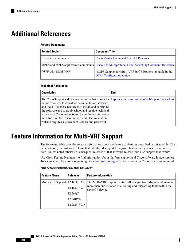
Additional ReferencesRelated Documents
Document TitleRelated Topic
Cisco Master Command List, All ReleasesCisco IOS commands
Cisco IOSMultiprotocol Label Switching Command ReferenceMPLS and MPLS applications commands
“OSPF Support for Multi-VRF in CE Routers” module in theOSPF Configuration Guide.
OSPF with Multi-VRF
Technical Assistance
LinkDescription
http://www.cisco.com/cisco/web/support/index.htmlTheCisco Support andDocumentationwebsite providesonline resources to download documentation, software,and tools. Use these resources to install and configurethe software and to troubleshoot and resolve technicalissues with Cisco products and technologies. Access tomost tools on the Cisco Support and Documentationwebsite requires a Cisco.com user ID and password.
Feature Information for Multi-VRF SupportThe following table provides release information about the feature or features described in this module. Thistable lists only the software release that introduced support for a given feature in a given software releasetrain. Unless noted otherwise, subsequent releases of that software release train also support that feature.
Use Cisco Feature Navigator to find information about platform support and Cisco software image support.To access Cisco Feature Navigator, go to www.cisco.com/go/cfn. An account on Cisco.com is not required.
Table 19: Feature Information for Multi-VRF Support
Feature InformationReleasesFeature Name
The Multi-VRF Support feature allows you to configure and maintainmore than one instance of a routing and forwarding table within thesame CE device.
12.1(11)EA1
12.1(20)EW
12.2(4)T
12.2(8)YN
12.2(25)EWA
Multi-VRF Support
MPLS: Layer 3 VPNs Configuration Guide, Cisco IOS Release 15M&T298
Multi-VRF SupportAdditional References

C H A P T E R 19MPLS VPN per Customer Edge (CE) Label
The MPLS VPN per Customer Edge (CE) Label feature allows you to configure a single VPN label at theprovider edge (PE) for every immediate next hop or set of next hops.
You can enable (or disable) the MPLS VPN per CE Label feature in global configuration mode.
• Finding Feature Information, on page 299• Prerequisites for MPLS VPN per CE Label, on page 299• Restrictions for MPLS VPN per CE Label, on page 300• Information About MPLS VPN per CE Label, on page 300• How to Configure MPLS VPN per CE Label, on page 301• Configuration Examples for MPLS VPN per CE Label, on page 302• Additional References, on page 303• Feature Information for MPLS VPN per CE Label, on page 303
Finding Feature InformationYour software release may not support all the features documented in this module. For the latest caveats andfeature information, see Bug Search Tool and the release notes for your platform and software release. Tofind information about the features documented in this module, and to see a list of the releases in which eachfeature is supported, see the feature information table.
Use Cisco Feature Navigator to find information about platform support and Cisco software image support.To access Cisco Feature Navigator, go to www.cisco.com/go/cfn. An account on Cisco.com is not required.
Prerequisites for MPLS VPN per CE Label• If your virtual routing and forwarding (VRF) domain has any of the following features enabled, disablethem before you configure the MPLS VPN per CE Label feature:
• External Border Gateway Protocol (EBGP) multipath feature
• Internal Border Gateway Protocol (IBGP) multipath feature
• Carrier Supporting Carrier (CSC) feature
• Before configuringMultiprotocol Label Switching (MPLS) Layer 3 VPNs, youmust install MPLS, LabelDistribution Protocol (LDP), and Cisco Express Forwarding in your network. All devices in the core,
MPLS: Layer 3 VPNs Configuration Guide, Cisco IOS Release 15M&T299

including the provider edge (PE) devices, must be able to support Cisco Express Forwarding and MPLSforwarding.
Restrictions for MPLS VPN per CE Label• Enabling the MPLS VPN per CE Label feature causes Border Gateway Protocol (BGP) reconvergence,which can result in data loss for traffic coming from the Multiprotocol Label Switching (MPLS) VPNcore.
You canminimize network disruption by enabling this feature during a scheduledMPLS maintenance window. Also, if possible, avoid enabling this feature on alive device.
Note
• IPv6 Provider Edge devices (6PE) are not supported.
• Prefix-Independent Convergence (PIC) is not supported. Per CE Label with only multipath is supported.You cannot use this feature with:
• Internal Border Gateway Protocol (IBGP) multipath feature
• Carrier Supporting Carrier (CSC) feature
• When per CE label is configured, MPLS Forwarding Infrastructure (MFI) has to back up key and labelinformation to a standby device. This will impact software downgrades.
• The BGP Best External feature provides the network with a backup external route to avoid loss ofconnectivity of the primary external route. This feature is not supported.
• Importing routes from protocols other than BGP on a PE device is not supported.
• Any network with a zero next hop is assigned one label per network, because the next hop cannot bereliably determined.
• Do not use per CE labels if there are multiple neighbors with the same address in a VRF domain.
• Only single hop EBGP is supported. Multihop EBGP is not supported.
• In high availability configurations, labels will be preserved after switchover from standby only if BGPGraceful Restart is configured before establishing BGP sessions.
Information About MPLS VPN per CE Label
MPLS VPN per CE Label FunctionalityThe provider edge (PE) devices store both local and remote routes and include a label entry for each route.For distributed platforms, the per-prefix labels consume memory. When there are many virtual routing andforwarding (VRF) domains and routes, the amount of memory that the per-prefix labels consume can become
MPLS: Layer 3 VPNs Configuration Guide, Cisco IOS Release 15M&T300
MPLS VPN per Customer Edge (CE) LabelRestrictions for MPLS VPN per CE Label

an issue. The purpose of using per CE label allocation is to avoid an additional lookup on the PE device'srouting table and to conserve label space.
The MPLS VPN per CE Label feature allows the same label to be used for all the routes advertised from aunique customer edge (CE) peer device. The PE device allocates one label for every immediate next hop (inmost cases, the next hop is a CE router). The label is directly mapped to the next hop so there is no VRF routelookup performed during data forwarding. However, the number of labels allocated is one for each CE ratherthan one for each prefix. As BGP is aware of all the next hops, it assigns a label for each next hop (not foreach PE-CE interface).
How to Configure MPLS VPN per CE Label
Configuring the per CE Label Feature
SUMMARY STEPS
1. enable2. configure terminal3. mpls label mode {vrf vrf-name | all-vrfs} protocol {bgp-vpnv4 | bgp-vpnv6 | all-afs} {per-ce}4. end5. show ip vrf detail6. show mpls forwarding-table
DETAILED STEPS
PurposeCommand or Action
Enters privileged EXEC mode.enableStep 1
Example: • Enter your password if prompted.
Device> enable
Enters global configuration mode.configure terminal
Example:
Step 2
Device# configure terminal
Configures the MPLS VPN per CE Label feature.mpls label mode {vrf vrf-name | all-vrfs} protocol{bgp-vpnv4 | bgp-vpnv6 | all-afs} {per-ce}
Step 3
Example:
Device(config)# mpls label mode all-vrfs protocolbgp-vpnv6 per-ce
Exits global configuration mode and returns to privilegedEXEC mode.
end
Example:
Step 4
Device(config)# end
MPLS: Layer 3 VPNs Configuration Guide, Cisco IOS Release 15M&T301
MPLS VPN per Customer Edge (CE) LabelHow to Configure MPLS VPN per CE Label

PurposeCommand or Action
Displays the VRF label mode.show ip vrf detail
Example:
Step 5
Device# show ip vrf detail
Displays the contents of theMultiprotocol Label Switching(MPLS) Label Forwarding Information Base (LFIB).
show mpls forwarding-table
Example:
Step 6
Device# show mpls forwarding-table
Configuration Examples for MPLS VPN per CE Label
Examples: MPLS VPN per CE LabelDevice> enableDevice# configure terminalDevice(config)# mpls label mode all-vrfs protocol bgp-vpnv6 per-ceDevice(config)# end
You can use show commands to view information about a per CE label configuration.
The following example shows how to display detailed information about the defined VPN routing andforwarding (VRF) instances and associated interfaces:PE1# show ip vrf detail
VRF red (VRF Id = 1); default RD 1:1; default VPNID <not set="">New CLI format, supports multiple address-familiesFlags: 0x180CInterfaces:Et1/0 Et2/0
VRF Table ID = 1Flags: 0x0Export VPN route-target communitiesRT:1:1
Import VPN route-target communitiesRT:1:1
No import route-mapNo global export route-mapNo export route-mapVRF label distribution protocol: not configuredVRF label allocation mode: per-ce
The following example shows how to display the contents of the MPLS Label Forwarding Information Base(LFIB):
PE1# show mpls forwarding-table
Local Outgoing Prefix Bytes Label Outgoing Next HopLabel Label or Tunnel Id Switched interface16 Pop Label 1.1.1.1/32 0 Et0/0 10.0.0.118 No Label nh-id(1) 0 Et2/0 10.0.2.219 No Label nh-id(2) 0 Et1/0 10.0.1.2
MPLS: Layer 3 VPNs Configuration Guide, Cisco IOS Release 15M&T302
MPLS VPN per Customer Edge (CE) LabelConfiguration Examples for MPLS VPN per CE Label

20 No Label nh-id(3) 0 Et1/0 10.0.1.222 No Label nh-id(5) 0 Et1/0 10.0.1.2
No Label nh-id(5) 0 Et2/0 10.0.2.2
Additional ReferencesRelated Documents
Document TitleRelated Topic
Cisco IOS Master Command List, All ReleasesCisco IOS commands
Cisco IOSMultiprotocol Label Switching Command ReferenceMPLS commands
Standards and RFCs
TitleStandard/RFC
BGP/MPLSRFC 2547
Technical Assistance
LinkDescription
http://www.cisco.com/cisco/web/support/index.htmlTheCisco Support andDocumentationwebsite providesonline resources to download documentation, software,and tools. Use these resources to install and configurethe software and to troubleshoot and resolve technicalissues with Cisco products and technologies. Access tomost tools on the Cisco Support and Documentationwebsite requires a Cisco.com user ID and password.
Feature Information for MPLS VPN per CE LabelThe following table provides release information about the feature or features described in this module. Thistable lists only the software release that introduced support for a given feature in a given software releasetrain. Unless noted otherwise, subsequent releases of that software release train also support that feature.
Use Cisco Feature Navigator to find information about platform support and Cisco software image support.To access Cisco Feature Navigator, go to www.cisco.com/go/cfn. An account on Cisco.com is not required.
MPLS: Layer 3 VPNs Configuration Guide, Cisco IOS Release 15M&T303
MPLS VPN per Customer Edge (CE) LabelAdditional References

Table 20: Feature Information for MPLS VPN per CE Label
Feature InformationReleasesFeature Name
TheMPLSVPN per CE Label feature allows you to configure a singleVPN label at the provider edge (PE) for every immediate next hop orset of next hops.
The following commands were introduced or modified: show mplsforwarding-table, mpls label mode.
15.4(1)TMPLS VPN per CE Label
MPLS: Layer 3 VPNs Configuration Guide, Cisco IOS Release 15M&T304
MPLS VPN per Customer Edge (CE) LabelFeature Information for MPLS VPN per CE Label

C H A P T E R 20IPv6 VRF Aware System Message Logging
The IPv6 VRF Aware System Message Logging feature enables a device to send system logging (syslog)messages to an IPv6-enabled syslog server connected through a VPN routing and forwarding (VRF) interface.You can use the logging information for network monitoring and troubleshooting. This feature extends thiscapability to network traffic connected through VRFs.
• Finding Feature Information, on page 305• Prerequisites for IPv6 VRF Aware System Message Logging, on page 305• Restrictions for IPv6 VRF Aware System Message Logging, on page 306• Information About IPv6 VRF Aware System Message Logging, on page 306• How to Configure IPv6 VRF Aware System Message Logging, on page 308• Configuration Examples for IPv6 VRF Aware System Message Logging, on page 312• Additional References for IPv6 VRF Aware System Message Logging, on page 313• Feature Information for IPv6 VRF Aware System Message Logging, on page 314
Finding Feature InformationYour software release may not support all the features documented in this module. For the latest caveats andfeature information, see Bug Search Tool and the release notes for your platform and software release. Tofind information about the features documented in this module, and to see a list of the releases in which eachfeature is supported, see the feature information table.
Use Cisco Feature Navigator to find information about platform support and Cisco software image support.To access Cisco Feature Navigator, go to www.cisco.com/go/cfn. An account on Cisco.com is not required.
Prerequisites for IPv6 VRF Aware System Message LoggingYou must configure a VPN routing and forwarding (VRF) instance on a routing device and associate the VRFwith an interface before you can configure the IPv6 VRF Aware System Message Logging feature.
MPLS: Layer 3 VPNs Configuration Guide, Cisco IOS Release 15M&T305

Restrictions for IPv6 VRF Aware System Message LoggingYou cannot specify a source address for virtual routing and forwarding (VRF) system logging messages. TheIPv6 VRF Aware System Message Logging feature uses the VRF interface address as the source address forall VRF aware system logging messages.
Information About IPv6 VRF Aware System Message Logging
Benefits of VRF Aware System Message LoggingA VPN routing and forwarding (VRF) instance is an extension of IP routing that provides multiple routinginstances. A VRF provides a separate IP routing and forwarding table to each VPN. You must configure aVRF on a routing device before you configure the VRF Aware System Message Logging feature.
After you configure the VRF Aware System Message Logging feature on a routing device, the device cansend system logging (syslog) messages to a syslog host through a VRF interface. Then you can use loggingmessages to monitor and troubleshoot network traffic connected through a VRF. If the VRF Aware SystemMessage Logging feature is not configured on a routing device, the routing device sends syslog messages tothe syslog host only through the global routing table.
You can receive system logging messages through a VRF interface on any device configured with a VRF,that is:
• On a provider edge (PE) device that is used withMultiprotocol Label Switching (MPLS) andmultiprotocolBorder Gateway Protocol (BGP) to provide a Layer 3 MPLS VPN network service.
• On a customer edge (CE) device that is configured for VRF-Lite, which is a VRF implementation withoutmultiprotocol BGP.
VRF Aware System Message Logging on a Provider Edge Device in an MPLSVPN Network
You can configure the VRF Aware System Message Logging feature on a provider edge (PE) device in aLayer 3 Multiprotocol Label Switching (MPLS) VPN network. The PE device can then send system logging(syslog) messages through a VPN routing and forwarding (VRF) interface to a syslog server located in theVPN.
The figure below shows an MPLS VPN network and the VRF Aware System Message Logging featureconfigured on a PE device associated with VRF VPN1. The PE device sends log messages through a VRFinterface to a syslog server located in VPN1. You can display the messages from the syslog server on aterminal.
MPLS: Layer 3 VPNs Configuration Guide, Cisco IOS Release 15M&T306
IPv6 VRF Aware System Message LoggingRestrictions for IPv6 VRF Aware System Message Logging
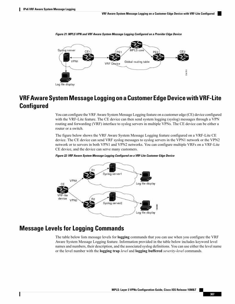
Figure 21: MPLS VPN and VRF Aware System Message Logging Configured on a Provider Edge Device
VRF Aware System Message Logging on a Customer Edge Device with VRF-LiteConfigured
You can configure the VRFAware SystemMessage Logging feature on a customer edge (CE) device configuredwith the VRF-Lite feature. The CE device can then send system logging (syslog) messages through a VPNrouting and forwarding (VRF) interface to syslog servers in multiple VPNs. The CE device can be either arouter or a switch.
The figure below shows the VRF Aware System Message Logging feature configured on a VRF-Lite CEdevice. The CE device can send VRF syslog messages to syslog servers in the VPN1 network or the VPN2network or to servers in both VPN1 and VPN2 networks. You can configure multiple VRFs on a VRF-LiteCE device, and the device can serve many customers.Figure 22: VRF Aware System Message Logging Configured on a VRF-Lite Customer Edge Device
Message Levels for Logging CommandsThe table below lists message levels for logging commands that you can use when you configure the VRFAware System Message Logging feature. Information provided in the table below includes keyword levelnames and numbers, their description, and the associated syslog definitions. You can use either the level nameor the level number with the logging trap level and logging buffered severity-level commands.
MPLS: Layer 3 VPNs Configuration Guide, Cisco IOS Release 15M&T307
IPv6 VRF Aware System Message LoggingVRF Aware System Message Logging on a Customer Edge Device with VRF-Lite Configured

Table 21: Message Levels for logging Commands
Syslog DefinitionDescriptionLevel NumberLevel Name
LOG_EMERGSystem unusable0emergencies
LOG_ALERTImmediate action needed1alerts
LOG_CRITCritical conditions2critical
LOG_ERRError conditions3errors
LOG_WARNINGWarning conditions4warnings
LOG_NOTICENormal but significant condition5notifications
LOG_INFOInformational messages only6informational
LOG_DEBUGDebugging messages7debugging
How to Configure IPv6 VRF Aware System Message Logging
Configuring VRF on a Routing DeviceConfiguring a VPN routing and forwarding (VRF) instance on a routing device helps provide customerconnectivity to a VPN. The routing device can be a provider edge (PE) device connected to a MultiprotocolLabel Switching (MPLS) VPN network or a customer edge (CE) device that is configured for VRF-Lite.
SUMMARY STEPS
1. enable2. configure terminal3. vrf definition vrf-name4. address-family ipv65. end
DETAILED STEPS
PurposeCommand or Action
Enables privileged EXEC mode.enableStep 1
Example: • Enter your password if prompted.Device> enable
Enters global configuration mode.configure terminal
Example:
Step 2
Device# configure terminal
Defines aVRF instance and enters VRF configurationmode.vrf definition vrf-nameStep 3
MPLS: Layer 3 VPNs Configuration Guide, Cisco IOS Release 15M&T308
IPv6 VRF Aware System Message LoggingHow to Configure IPv6 VRF Aware System Message Logging

PurposeCommand or Action
Example: • The vrf-name argument is a name assigned to the VRF.Device (config)# vrf definition vpn1
Enables IPv6 address-family for the defined VRF and entersaddress family configuration mode.
address-family ipv6
Example:
Step 4
Device(config-vrf)# address-family ipv6
Exits address family configuration mode and returns toprivileged EXEC mode.
end
Example:
Step 5
Device(config-vrf-af)# end
Associating a VRF with an InterfaceAfter configuring the VPN routing and forwarding (VRF) instance and associating it with an interface, youcan configure the VRF Aware System Message Logging feature on the routing device.
You cannot configure a source address for VRF system logging messages. The VRF Aware System MessageLogging feature uses the VRF interface address as the source address for all VRF-aware system loggingmessages.
Note
Before you begin
A VRF must be associated with an interface before you can forward VPN traffic.
SUMMARY STEPS
1. enable2. configure terminal3. interface type number4. vrf forwarding vrf-name5. no ipv6 address6. ipv6 address address.prefix7. end
DETAILED STEPS
PurposeCommand or Action
Enables privileged EXEC mode.enableStep 1
Example: • Enter your password if prompted.Device> enable
Enters global configuration mode.configure terminal
Example:
Step 2
MPLS: Layer 3 VPNs Configuration Guide, Cisco IOS Release 15M&T309
IPv6 VRF Aware System Message LoggingAssociating a VRF with an Interface

PurposeCommand or ActionDevice# configure terminal
Configures an interface type and enters interfaceconfiguration mode.
interface type number
Example:
Step 3
• The type argument is the type of interface to beconfigured.
Device (config)# interface FastEthernet 0/0/0
• The number argument is the port, connector, orinterface card number. The numbers are assigned atthe factory at the time of installation or when the port,connector, or interface card is added to a system. Usethe show interfaces command in privileged EXECmode to view the available interfaces.
Associates a VRF with an interface or subinterface.vrf forwarding vrf-nameStep 4
Example: • The vrf-name argument associates the interface withthe specified VRF.Device(config-if)# vrf forwarding vpn1
Removes the existing IPv6 address set for an interface.no ipv6 address
Example:
Step 5
Device(config-if)# no ipv6 address
Assigns an IPv6 address for the interface.ipv6 address address.prefix
Example:
Step 6
Device(config-if)# ipv6 address 2001:DB8::1/32
Exits interface configuration mode and returns to privilegedEXEC mode.
end
Example:
Step 7
Device(config-if)# end
Configuring VRF as a Source Interface for Logging on a Routing Device
Before you begin
You must perform the following tasks before you perform this task:
• Configure a virtual routing and forwarding (VRF) instance on a routing device.
• Associate a VRF with an interface.
SUMMARY STEPS
1. enable2. configure terminal3. logging source-interface interface-type interface-number vrf vrf-name4. logging host ipv6 ipv6-address vrf vrf-name
MPLS: Layer 3 VPNs Configuration Guide, Cisco IOS Release 15M&T310
IPv6 VRF Aware System Message LoggingConfiguring VRF as a Source Interface for Logging on a Routing Device

5. end
DETAILED STEPS
PurposeCommand or Action
Enables privileged EXEC mode.enableStep 1
Example: • Enter your password if prompted.Device> enable
Enters global configuration mode.configure terminal
Example:
Step 2
Device# configure terminal
Configures the VRF interface as the source interface forlogging.
logging source-interface interface-type interface-numbervrf vrf-name
Example:
Step 3
Device (config)# logging source-interfaceFastEthernet 0/0/0 vrf vpn1
Configures and associates the IPv6-enabled logging hostwith the VRF.
logging host ipv6 ipv6-address vrf vrf-name
Example:
Step 4
Device(config)# logging host ipv6 2001:DB8:: vrfvpn1
Exits global configuration mode and returns to privilegedEXEC mode.
end
Example:
Step 5
Device(config)# end
Verifying IPv6 VRF Aware System Message Logging
SUMMARY STEPS
1. enable2. show running-config | include logging3. show logging
DETAILED STEPS
Step 1 enable
Enables privileged EXEC mode.
• Enter your password if prompted.
Example:Device> enable
MPLS: Layer 3 VPNs Configuration Guide, Cisco IOS Release 15M&T311
IPv6 VRF Aware System Message LoggingVerifying IPv6 VRF Aware System Message Logging
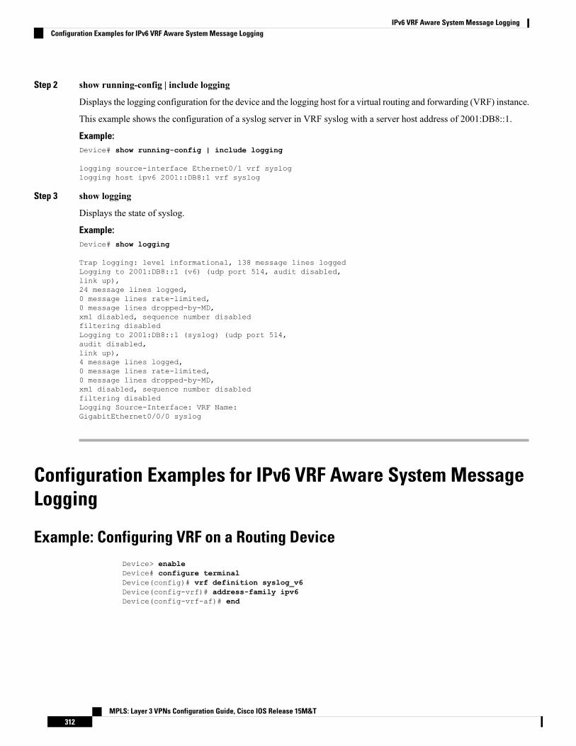
Step 2 show running-config | include logging
Displays the logging configuration for the device and the logging host for a virtual routing and forwarding (VRF) instance.
This example shows the configuration of a syslog server in VRF syslog with a server host address of 2001:DB8::1.
Example:Device# show running-config | include logging
logging source-interface Ethernet0/1 vrf sysloglogging host ipv6 2001::DB8:1 vrf syslog
Step 3 show logging
Displays the state of syslog.
Example:Device# show logging
Trap logging: level informational, 138 message lines loggedLogging to 2001:DB8::1 (v6) (udp port 514, audit disabled,link up),24 message lines logged,0 message lines rate-limited,0 message lines dropped-by-MD,xml disabled, sequence number disabledfiltering disabledLogging to 2001:DB8::1 (syslog) (udp port 514,audit disabled,link up),4 message lines logged,0 message lines rate-limited,0 message lines dropped-by-MD,xml disabled, sequence number disabledfiltering disabledLogging Source-Interface: VRF Name:GigabitEthernet0/0/0 syslog
Configuration Examples for IPv6 VRF Aware System MessageLogging
Example: Configuring VRF on a Routing DeviceDevice> enableDevice# configure terminalDevice(config)# vrf definition syslog_v6Device(config-vrf)# address-family ipv6Device(config-vrf-af)# end
MPLS: Layer 3 VPNs Configuration Guide, Cisco IOS Release 15M&T312
IPv6 VRF Aware System Message LoggingConfiguration Examples for IPv6 VRF Aware System Message Logging

Example: Associating a VRF with an InterfaceDevice> enableDevice# configure terminalDevice(config)# interface FastEthernet 0/0/0Device(config-if)# vrf forwarding vpn1Device(config-if)# no ipv6 addressDevice(config-if)# ipv6 address 2001:DB8::1/32Device(config-if)# end
Example: Configuring VRF as a Source Interface for Logging on a RoutingDevice
Device> enableDevice# configure terminalDevice(config)# logging source-interface FastEthernet 0/0/0 vrf vpn1Device(config)# logging host ipv6 address 2001:DB8::1 vrf vpn1Device(config)# end
Additional References for IPv6 VRF Aware System MessageLogging
Related Documents
Document TitleRelated Topic
Cisco IOS Master Commands List, All ReleasesCisco IOS commands
Cisco IOS Multiprotocol Label Switching CommandReference
MPLS and MPLS applications commands
“Configuring VRF-lite” chapter in the Catalyst 4500 SeriesSwitch Cisco IOS Software Configuration Guide
Concepts and tasks for configuring VRF-liteon a Catalyst 4500 switch
“ConfiguringVRF-lite” chapter in theEthernet Card SoftwareFeature and Configuration Guide for the Cisco ONS 15454SDH, ONS 15454, and ONS 15327
Concepts and tasks for configuring VRF Liteon ML-Series Ethernet cards
MPLS: Layer 3 VPNs Configuration Guide, Cisco IOS Release 15M&T313
IPv6 VRF Aware System Message LoggingExample: Associating a VRF with an Interface

Technical Assistance
LinkDescription
http://www.cisco.com/cisco/web/support/index.htmlThe Cisco Support website provides extensive onlineresources, including documentation and tools fortroubleshooting and resolving technical issues withCisco products and technologies.
To receive security and technical information aboutyour products, you can subscribe to various services,such as the Product Alert Tool (accessed from FieldNotices), the Cisco Technical Services Newsletter, andReally Simple Syndication (RSS) Feeds.
Access to most tools on the Cisco Support websiterequires a Cisco.com user ID and password.
Feature Information for IPv6 VRF Aware System MessageLogging
The following table provides release information about the feature or features described in this module. Thistable lists only the software release that introduced support for a given feature in a given software releasetrain. Unless noted otherwise, subsequent releases of that software release train also support that feature.
Use Cisco Feature Navigator to find information about platform support and Cisco software image support.To access Cisco Feature Navigator, go to www.cisco.com/go/cfn. An account on Cisco.com is not required.
Table 22: Feature Information for IPv6 VRF Aware System Message Logging
Feature InformationReleasesFeature Name
The IPv6 VRF Aware System Message Logging feature enablesa device to send system logging (syslog) messages to anIPv6-enabled syslog server connected through a VPN routing andforwarding (VRF) interface. You can use the logging informationfor network monitoring and troubleshooting. This feature extendsthis capability to network traffic connected through VRFs.
The following commandsweremodified: logging source-interfaceand logging host.
Cisco IOS15.4(3)M
IPv6 VRF AwareSystem MessageLogging
MPLS: Layer 3 VPNs Configuration Guide, Cisco IOS Release 15M&T314
IPv6 VRF Aware System Message LoggingFeature Information for IPv6 VRF Aware System Message Logging


![Clase 16 - VPNs[1]](https://img.dokumen.tips/doc/110x75/563dba78550346aa9aa5e53e/clase-16-vpns1.jpg)


![Juniper Advanced VPNs Update]](https://img.dokumen.tips/doc/110x75/5524d3364a7959c8488b48c6/juniper-advanced-vpns-update.jpg)