Embed Size (px)
Citation preview
© 2005 Microchip Technology Inc. DS51295F
MPLAB® C18C COMPILER
GETTING STARTED

Note the following details of the code protection feature on Microchip devices:
• Microchip products meet the specification contained in their particular Microchip Data Sheet.
• Microchip believes that its family of products is one of the most secure families of its kind on the market today, when used in the intended manner and under normal conditions.
• There are dishonest and possibly illegal methods used to breach the code protection feature. All of these methods, to our knowledge, require using the Microchip products in a manner outside the operating specifications contained in Microchip’s Data Sheets. Most likely, the person doing so is engaged in theft of intellectual property.
• Microchip is willing to work with the customer who is concerned about the integrity of their code.
• Neither Microchip nor any other semiconductor manufacturer can guarantee the security of their code. Code protection does not mean that we are guaranteeing the product as “unbreakable.”
Code protection is constantly evolving. We at Microchip are committed to continuously improving the code protection features of ourproducts. Attempts to break Microchip’s code protection feature may be a violation of the Digital Millennium Copyright Act. If such actsallow unauthorized access to your software or other copyrighted work, you may have a right to sue for relief under that Act.
Information contained in this publication regarding deviceapplications and the like is provided only for your convenienceand may be superseded by updates. It is your responsibility toensure that your application meets with your specifications.MICROCHIP MAKES NO REPRESENTATIONS OR WAR-RANTIES OF ANY KIND WHETHER EXPRESS OR IMPLIED,WRITTEN OR ORAL, STATUTORY OR OTHERWISE,RELATED TO THE INFORMATION, INCLUDING BUT NOTLIMITED TO ITS CONDITION, QUALITY, PERFORMANCE,MERCHANTABILITY OR FITNESS FOR PURPOSE.Microchip disclaims all liability arising from this information andits use. Use of Microchip’s products as critical components inlife support systems is not authorized except with expresswritten approval by Microchip. No licenses are conveyed,implicitly or otherwise, under any Microchip intellectual propertyrights.
DS51295F-page ii
Trademarks
The Microchip name and logo, the Microchip logo, Accuron, dsPIC, KEELOQ, microID, MPLAB, PIC, PICmicro, PICSTART, PRO MATE, PowerSmart, rfPIC, and SmartShunt are registered trademarks of Microchip Technology Incorporated in the U.S.A. and other countries.
AmpLab, FilterLab, Migratable Memory, MXDEV, MXLAB, PICMASTER, SEEVAL, SmartSensor and The Embedded Control Solutions Company are registered trademarks of Microchip Technology Incorporated in the U.S.A.
Analog-for-the-Digital Age, Application Maestro, dsPICDEM, dsPICDEM.net, dsPICworks, ECAN, ECONOMONITOR, FanSense, FlexROM, fuzzyLAB, In-Circuit Serial Programming, ICSP, ICEPIC, Linear Active Thermistor, MPASM, MPLIB, MPLINK, MPSIM, PICkit, PICDEM, PICDEM.net, PICLAB, PICtail, PowerCal, PowerInfo, PowerMate, PowerTool, rfLAB, rfPICDEM, Select Mode, Smart Serial, SmartTel, Total Endurance and WiperLock are trademarks of Microchip Technology Incorporated in the U.S.A. and other countries.
SQTP is a service mark of Microchip Technology Incorporated in the U.S.A.
All other trademarks mentioned herein are property of their respective companies.
© 2005, Microchip Technology Incorporated, Printed in the U.S.A., All Rights Reserved.
Printed on recycled paper.
© 2005 Microchip Technology Inc.
Microchip received ISO/TS-16949:2002 quality system certification for its worldwide headquarters, design and wafer fabrication facilities in Chandler and Tempe, Arizona and Mountain View, California in October 2003. The Company’s quality system processes and procedures are for its PICmicro® 8-bit MCUs, KEELOQ® code hopping devices, Serial EEPROMs, microperipherals, nonvolatile memory and analog products. In addition, Microchip’s quality system for the design and manufacture of development systems is ISO 9001:2000 certified.
MPLAB® C18 C COMPILERGETTING STARTED
Table of Contents
Preface ........................................................................................................................... 1
Chapter 1. Overview1.1 Introduction ..................................................................................................... 91.2 Tools for Embedded Systems Programming .................................................. 91.3 System Requirements .................................................................................. 111.4 Directories .................................................................................................... 121.5 About the Language Tools ........................................................................... 131.6 Execution Flow ............................................................................................. 14
Chapter 2. Installation2.1 Introduction ................................................................................................... 152.2 Installing MPLAB C18 .................................................................................. 152.3 Uninstalling MPLAB C18 .............................................................................. 24
Chapter 3. Project Basics and MPLAB IDE Configuration3.1 Introduction ................................................................................................... 253.2 Project Overview .......................................................................................... 253.3 Creating a File .............................................................................................. 263.4 Creating Projects .......................................................................................... 263.5 Using the Project Window ............................................................................ 303.6 Configuring Language Tool Locations .......................................................... 303.7 Verify Installation and Build Options ............................................................. 333.8 Building and Testing ..................................................................................... 35
Chapter 4. Beginning Programs4.1 Introduction ................................................................................................... 394.2 Program 1: “Hello, world!” ............................................................................ 394.3 Program 2: Light LED Using Simulator ........................................................ 444.4 Program 3: Flash LED Using Simulator ....................................................... 494.5 Using the Demo Board ................................................................................. 55
Chapter 5. Features5.1 Overview ...................................................................................................... 595.2 MPLAB Project Build Options ....................................................................... 595.3 Demonstration: Code Optimization .............................................................. 645.4 Demonstration: Displaying Data in Watch Windows .................................... 76
© 2005 Microchip Technology Inc. DS51295F-page iii
MPLAB® C18 C Compiler Getting Started
Chapter 6. Architecture6.1 Introduction ................................................................................................... 896.2 PIC18XXXX Architecture .............................................................................. 906.3 MPLAB C18 Start-up Code .......................................................................... 946.4 #pragma Directive ........................................................................................ 946.5 Sections ........................................................................................................ 966.6 SFRS, Timers SW/HW ................................................................................. 976.7 Interrupts ...................................................................................................... 986.8 Math and I/O Libraries .................................................................................. 98
Chapter 7. Troubleshooting7.1 Introduction ................................................................................................... 997.2 Error Messages .......................................................................................... 1007.3 Frequently Asked Questions (FAQs) .......................................................... 101
Glossary .....................................................................................................................107
Index ...........................................................................................................................121
Worldwide Sales and Service ...................................................................................124
DS51295F-page iv © 2005 Microchip Technology Inc.

MPLAB® C18 C COMPILER
GETTING STARTEDPreface
INTRODUCTION
This document is designed to help an embedded system engineer get started quickly using Microchip’s MPLAB® C18 C compiler. PICmicro® microcontroller applications can be developed rapidly using MPLAB C18 with PIC18 PICmicro MCUs, MPLINK™ linker and MPLAB IDE. Please refer to the MPLAB® C18 C Compiler User’s Guide (DS51288) for more details on the features of the compiler mentioned in this document.
The information in this guide is for the engineer or student who comes from a back-ground in microcontrollers, understands the basic concepts of an 8-bit microcontroller and has some familiarity with the C programming language.
Items discussed in this chapter are:
• Document Layout• Conventions Used in this Guide• Recommended Reading• The Microchip Web Site• Development Systems Customer Change Notification Service• Customer Support
NOTICE TO CUSTOMERS
All documentation becomes dated, and this manual is no exception. Microchip tools and documentation are constantly evolving to meet customer needs, so some actual dialogs and/or tool descriptions may differ from those in this document. Please refer to our web site (www.microchip.com) to obtain the latest documentation available.
Documents are identified with a “DS” number. This number is located on the bottom of each page, in front of the page number. The numbering convention for the DS number is “DSXXXXXA”, where “XXXXX” is the document number and “A” is the revision level of the document.
For the most up-to-date information on development tools, see the MPLAB® IDE on-line help. Select the Help menu, and then Topics to open a list of available on-line help files.
© 2005 Microchip Technology Inc. DS51295F-page 1
MPLAB® C18 C Compiler Getting Started
DOCUMENT LAYOUT
• Chapter 1. Overview – provides an overview of the MPLAB C18 compiler, its components and its integration with MPLAB Integrated Development Environment (IDE).
• Chapter 2. Installation – provides a step-by-step guide through the installation process of MPLAB C18 Compiler.
• Chapter 3. Project Basics and MPLAB IDE Configuration – covers the MPLAB IDE setup for use with MPLAB C18 using MPLAB projects and MPLAB SIM simu-lator, and references the basics of MPLAB IDE configuration for running the examples and applications in this guide.
• Chapter 4. Beginning Programs – contains simple examples, starting with a simple “Hello, world!” introductory program, followed by a program to flash LEDs connected to a PIC18 microcontroller.
• Chapter 5. Features – outlines the overall feature set of the MPLAB C18 com-piler and provides code demonstrations of optimization and illustrations of the use of MPLAB watch windows to view data elements and structures.
• Chapter 6. Architecture – explores the PIC18 architecture, with special features of the MPLAB C18 Compiler that may be different from other C compilers.
• Chapter 7. Troubleshooting – has a list of common error messages and frequently asked technical questions, along with answers and pointers for dealing with problems.
DS51295F-page 2 © 2005 Microchip Technology Inc.
Preface
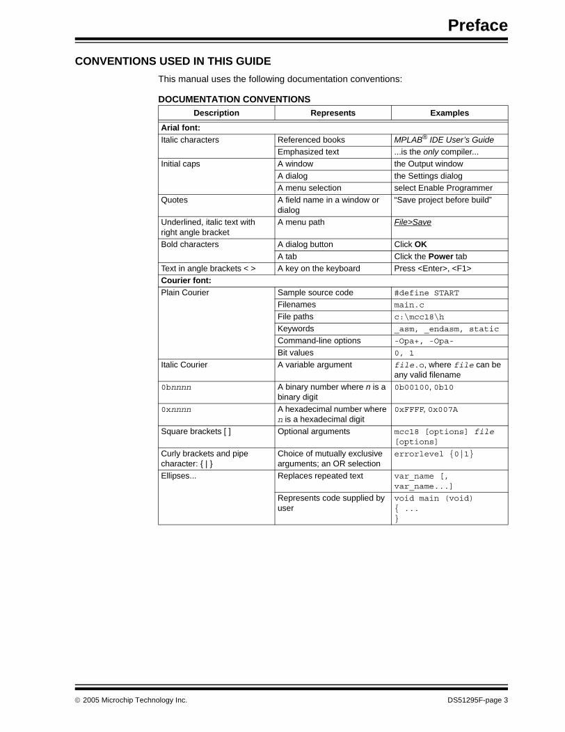
CONVENTIONS USED IN THIS GUIDE
This manual uses the following documentation conventions:
DOCUMENTATION CONVENTIONSDescription Represents Examples
Arial font:Italic characters Referenced books MPLAB® IDE User’s Guide
Emphasized text ...is the only compiler...Initial caps A window the Output window
A dialog the Settings dialogA menu selection select Enable Programmer
Quotes A field name in a window or dialog
“Save project before build”
Underlined, italic text with right angle bracket
A menu path File>Save
Bold characters A dialog button Click OKA tab Click the Power tab
Text in angle brackets < > A key on the keyboard Press <Enter>, <F1>Courier font:Plain Courier Sample source code #define START
Filenames main.c
File paths c:\mcc18\h
Keywords _asm, _endasm, static
Command-line options -Opa+, -Opa-
Bit values 0, 1
Italic Courier A variable argument file.o, where file can be any valid filename
0bnnnn A binary number where n is a binary digit
0b00100, 0b10
0xnnnn A hexadecimal number where n is a hexadecimal digit
0xFFFF, 0x007A
Square brackets [ ] Optional arguments mcc18 [options] file [options]
Curly brackets and pipe character: { | }
Choice of mutually exclusive arguments; an OR selection
errorlevel {0|1}
Ellipses... Replaces repeated text var_name [, var_name...]
Represents code supplied by user
void main (void){ ...}
© 2005 Microchip Technology Inc. DS51295F-page 3
MPLAB® C18 C Compiler Getting Started
RECOMMENDED READING
PIC18 DEVELOPMENT REFERENCES
For more information on included libraries and precompiled object files for the compilers, the operation of MPLAB IDE and the use of other tools, the following are recommended reading.
MPLAB-C18-README.txt
For the latest information on using MPLAB C18 C Compiler, read the MPLAB-C18-README.txt file (ASCII text) included with the software. This readme file contains updated information that may not be included in this document.
Readme for XXX.txt
For the latest information on other Microchip tools (MPLAB IDE, MPLINK linker, etc.), read the associated readme files (ASCII text file) included with the software.
MPLAB® C18 C Compiler User’s Guide (DS51288)
Comprehensive guide that describes the operation and features of Microchip’s MPLAB C18 C compiler for PIC18 devices.
PIC18 Configuration Settings Addendum (DS51537)
Lists the Configuration bit settings for the Microchip PIC18 devices supported by the MPLAB C18 C compiler’s #pragma config directive and the MPASM CONFIG directive.
MPLAB C18 C Compiler Libraries (DS51297)
References MPLAB C18 libraries and precompiled object files. Lists all library functions provided with the MPLAB C18 C Compiler with detailed descriptions of their use.
MPLAB® IDE User’s Guide (DS51519)
Describes how to set up the MPLAB IDE software and use it to create projects and program devices.
MPASM™ Assembler, MPLINK™ Object Linker, MPLIB™ Object Librarian User’s Guide (DS33014)
Describes how to use the Microchip PICmicro MCU assembler (MPASM), linker (MPLINK), and librarian (MPLIB).
PICmicro® 18C MCU Family Reference Manual (DS39500)
Focuses on the PIC18 family of devices. The operation of the PIC18 family architecture and peripheral modules is explained, but does not cover the specifics of each device.
PIC18 Device Data Sheets
Data sheets describe the operation and electrical specifications of PIC18 devices.
To obtain any of the above listed documents, visit the Microchip web site (www.microchip.com) to retrieve these documents in Adobe Acrobat (.pdf) format.
DS51295F-page 4 © 2005 Microchip Technology Inc.
Preface
C LANGUAGE AND OTHER TEXTBOOKS
There are many textbooks and specialized texts to help with C in general, some covering embedded application using Microchip microcontrollers,.
American National Standard for Information Systems – Programming Language – C. American National Standards Institute (ANSI), 11 West 42nd. Street, New York, New York, 10036.
This standard specifies the form and establishes the interpretation of programs expressed in the programming language C. Its purpose is to promote portability, reliability, maintainability, and efficient execution of C language programs on a variety of computing systems.
Harbison, Samuel P. and Steele, Guy L., C: A Reference Manual, Fourth Edition. Prentice-Hall, Englewood Cliffs, New Jersey 07632.
Covers the C programming language in great detail. This book is an authoritative reference manual that provides a complete description of the C language, the run-time libraries and a style of C programming that emphasizes correctness, portability and maintainability.
Huang, Han-Way. PIC® Microcontroller: An Introduction to Software & Hardware Interfacing. Thomson Delmar Learning, Clifton Park, New York 12065.
Presents a thorough introduction to the Microchip PIC18 microcontroller family, including all the PIC microcontroller (MCU) programming and interfacing for peripheral functions. Both PIC MCU assembly language and the MPLAB C18 C compiler are used in this college level textbook.
Kernighan, Brian W. and Ritchie, Dennis M. The C Programming Language, Second Edition. Prentice Hall, Englewood Cliffs, New Jersey 07632.
Presents a concise exposition of C as defined by the ANSI standard. This book is an excellent reference for C programmers.
Kochan, Steven G. Programming In ANSI C, Revised Edition. Hayden Books, Indianapolis, Indiana 46268.
Another excellent reference for learning ANSI C, used in colleges and universities.
Peatman, John B. Embedded Design with the PIC18F452 Microcontroller, First Edition. Pearson Education, Inc., Upper Saddle River, New Jersey 07458.
Focuses on Microchip Technology’s PIC18FXXX family and writing enhanced application code.
Van Sickle, Ted. Programming Microcontrollers in C, First Edition. LLH Technology Publishing, Eagle Rock, Virginia 24085.
Covers the basic principles of programming with C for microcontrollers.
Standards Committee of the IEEE Computer Society – IEEE Standard for Binary Floating-Point Arithmetic. The Institute of Electrical and Electronics Engineers, Inc., 345 East 47th Street, New York, New York 10017.
This standard describes the floating-point format used in MPLAB C18.
© 2005 Microchip Technology Inc. DS51295F-page 5
MPLAB® C18 C Compiler Getting Started
APPLICATION NOTES
Microchip provides a large library of application notes, many written to be compatible with the MPLAB C18 C compiler. Here are a few. Check the Microchip web site for recent additions.
• AN953 Data Encryption Routines for the PIC18• AN851 A FLASH Bootloader for PIC16 and PIC18 Devices• AN937 Implementing a PID Controller Using a PIC18 MCU• AN914 Dynamic Memory Allocation for the MPLAB C18 C Compiler• AN991 Using the C18 Compiler and the MSSP to Interface I2C™ EEPROMs with
PIC18 Devices• AN878 PIC18C ECAN C Routines• AN738 PIC18C CAN Routines in ‘C’• AN930 J1939 C LIbrary for CAN-Enabled PICmicro® MCUs
DESIGN CENTERS
The Microchip web site at www.microchip.com has many design centers with informa-tion to get started in a particular industry segment. These design centers include source code, application notes, web resources and recommended Microchip MCUs for particular applications.
These are some of the design centers available:
• Getting Started with Microchip• Automotive Solutions• High Pin Count/High Density Memory• KEELOQ® Authentication solutions• Battery Management Solutions• LCD Solutions• Connectivity Solutions
- Physical Protocols: CAN, LIN, USB- Wireless Protocols: ZigBee™, Infrared, rfPIC®
- Internet Protocols: TCP/IP• Low-Power Solutions• Designing for Mechatronics• Motor Control Solutions• Home Appliance Solutions• World’s Smallest Microcontrollers
DS51295F-page 6 © 2005 Microchip Technology Inc.

Preface
THE MICROCHIP WEB SITE
Microchip provides online support via our WWW site at www.microchip.com. This web site is used as a means to make files and information easily available to customers. Accessible by using Internet browsers, the web site contains the following information:
• Product Support – Data sheets and errata, application notes and sample pro-grams, design resources, user’s guides and hardware support documents, latest software releases and archived software
• General Technical Support – Frequently Asked Questions (FAQ), technical support requests, online discussion groups, Microchip consultant program member listing
• Business of Microchip – Product selector and ordering guides, latest Microchip press releases, listing of seminars and events, listings of Microchip sales offices, distributors and factory representatives
DEVELOPMENT SYSTEMS CUSTOMER CHANGE NOTIFICATION SERVICE
Microchip’s Customer Notification service helps keep customers current on Microchip products. Subscribers will receive e-mail notification whenever there are changes, updates, revisions or errata related to a specified product family or development tool of interest.
To register, access the Microchip web site at www.microchip.com, click on Customer Change Notification and follow the registration instructions.
The Development Systems product group categories are:
• Compilers – The latest information on Microchip C compilers and other language tools. These include the MPLAB C18 and MPLAB C30 C compilers, MPASM and MPLAB ASM30 assemblers, MPLINK and MPLAB LINK30 object linkers and MPLIB and MPLAB LIB30 object librarians.
• Emulators – The latest information on Microchip in-circuit emulators.This includes the MPLAB ICE 2000 and MPLAB ICE 4000.
• In-Circuit Debuggers – The latest information on the Microchip in-circuit debugger, MPLAB ICD 2.
• MPLAB IDE – The latest information on Microchip MPLAB IDE, the Windows® Integrated Development Environment for development systems tools. This list is focused on the MPLAB IDE and MPLAB SIM simulators, MPLAB Project Manager and general editing and debugging features.
• Programmers – The latest information on Microchip programmers. These include the MPLAB PM3 device programmer and the PICSTART® Plus development programmer.
CUSTOMER SUPPORT
Users of Microchip products can receive assistance through several channels:
• Distributor or Representative• Local Sales Office• Field Application Engineer (FAE)• Technical Support
Customers should contact their distributor, representative or field application engineer (FAE) for support. Local sales offices are also available to help customers. A listing of sales offices and locations is included in the back of this document.
Technical support is available through the web site at: http://support.microchip.com.
© 2005 Microchip Technology Inc. DS51295F-page 7

MPLAB® C18 C Compiler Getting Started
NOTES:
DS51295F-page 8 © 2005 Microchip Technology Inc.
MPLAB® C18 C COMPILER
GETTING STARTEDChapter 1. Overview
1.1 INTRODUCTION
This chapter introduces software tools used for embedded systems programming. It examines the functions and differences between compilers and assemblers, and the advantages of the C language. MPLAB C18 directory structures, the various language tool executables and the execution flow are also presented.
Included in this chapter are these topics:
• Tools for Embedded Systems Programming• System Requirements• Directories• About the Language Tools• Execution Flow
1.2 TOOLS FOR EMBEDDED SYSTEMS PROGRAMMING
1.2.1 MPLAB C18 C Compiler
MPLAB C18 C Compiler is a cross-compiler that runs on a PC and produces code that can be executed by the Microchip PIC18XXXX family of microcontrollers. Like an assembler, the MPLAB C18 compiler translates human-understandable statements into ones and zeros for the microcontroller to execute. Unlike an assembler, the compiler does not do a one-to-one translation of machine mnemonics into machine code.
MPLAB C18 takes standard C statements, such as “if(x==y)” and “temp=0x27”, and converts them into PIC18XXXX machine code. The compiler incorporates a good deal of intelligence in this process. It can optimize code using routines that were employed on one C function to be used by other C functions. The compiler can rearrange code, eliminate code that will never be executed, share common code fragments among multiple functions, and can identify data and registers that are used inefficiently, optimizing their access.
Code is written using standard ANSI C notation. Source code is compiled into blocks of program code and data which are then “linked” with other blocks of code and data, then placed into the various memory regions of the PIC18XXXX microcontroller. This process is called a “build,” and it is often executed many times in program development as code is written, tested and debugged. This process can be made more intelligent by using a “make” facility, which invokes the compiler only for those C source files in the project that have changed since the last build, resulting in faster project build times.
MPLAB C18 compiler and its associated tools, such as the linker and assembler, can be invoked from the command line to build a .HEX file that can be programmed into a PIC18XXXX device. MPLAB C18 and its other tools can also be invoked from within MPLAB IDE. The MPLAB graphical user interface serves as a single environment to write, compile and debug code for embedded applications.
The MPLAB dialogs and project manager handle most of the details of the compiler, assembler and linker, allowing the task of writing and debugging the application to remain the main focus.
© 2005 Microchip Technology Inc. DS51295F-page 9

MPLAB® C18 C Compiler Getting Started
MPLAB C18 compiler makes development of embedded systems applications easier because it uses the C standard language. There are many books that teach the C language, and some are referenced in the Preface “Recommended Reading”. This guide will assume an understanding of the fundamentals of programming in C. The advantage of the C language is that it is widely used, is portable across different archi-tectures, has many references and textbooks, and is easier to maintain and extend than assembly language. Additionally, MPLAB C18 can compile extremely efficient code for the PIC18XXXX microcontrollers.
1.2.2 MPASM Cross-Assembler and MPLINK Linker
Often, both a cross-assembler and a cross-compiler are used to write code for a project. MPASM is a component of the MPLAB IDE and it works in conjunction with MPLINK to link assembly language code sections with C code from the MPLAB C18 C Compiler.
Assembly language routines are practical for small sections of code that need to run very fast, or in a strictly defined time.
1.2.3 Other Tools
In this guide, examples will be written and built with MPLAB C18 Compiler through the graphical user interface and development environment of MPLAB IDE. The MPLAB IDE Getting Started guide has tutorials and walk-throughs to help understand MPLAB IDE. Additional assembly language and linker information can be referenced in the MPASM™ Assembler, MPLINK™ Object Linker, MPLIB™ Object Librarian User’s Guide.
Microchip’s PICDEM™ 2 Plus can use a PIC18F452 as its main microcontroller, and the examples here will work with this development board, flashing LEDs on this board.
Likewise, the MPLAB ICD 2 can be used to program the PIC18F452 for the PICDEM 2 Plus development board and debug the programs. These hardware tools are not required to run the examples in this guide. Debugging can be done within the free MPLAB IDE using MPLAB SIM, the PIC18XXXX simulator.
Note: While the execution time of code created by a compiler can become nearly as fast as code created using assembly language, it is constrained by the fact that it is a translation process, ending in machine code that could have been generated from assembly language, so it can never run faster than assembly language code.
DS51295F-page 10 © 2005 Microchip Technology Inc.

Overview
1.3 SYSTEM REQUIREMENTS
The suggested system requirements for using MPLAB C18 and the MPLAB IDE are:
• Intel® Pentium® class PC running Microsoft® 32-bit Windows operating system (Windows 2000, Windows XP Home or Windows XP Professional)
• Approximately 250 MB hard disk space• Optional hardware tools for some of the examples in this guide:
- PICDEM 2 Plus Development Board and power supply- MPLAB ICD 2 In-Circuit Debugger (requires serial or USB connection)
Although MPLAB C18 can be used without MPLAB IDE, this guide demonstrates its use within the MPLAB integrated development environment. MPLAB IDE should be installed before installing MPLAB C18. The default installation for MPLAB IDE may have preset selections. When installing MPLAB IDE for use with MPLAB C18, at a minimum, these components must be selected (see Figure 1-1):
• MPLAB IDE Device Support- 8-bit MCUs
• Microchip Applications- MPLAB IDE- MPLAB SIM- MPASM Suite (this is also installed with MPLAB C18, so it doesn’t need to be
installed with MPLAB IDE)
FIGURE 1-1: MPLAB® IDE INSTALLATION MENU
* Optional. If an MPLAB ICD 2 is available for programming and debugging, this should be selected.
© 2005 Microchip Technology Inc. DS51295F-page 11
MPLAB® C18 C Compiler Getting Started
1.4 DIRECTORIES
MPLAB C18 can be installed anywhere on the PC. Its default installation directory is the C:\mcc18 folder.
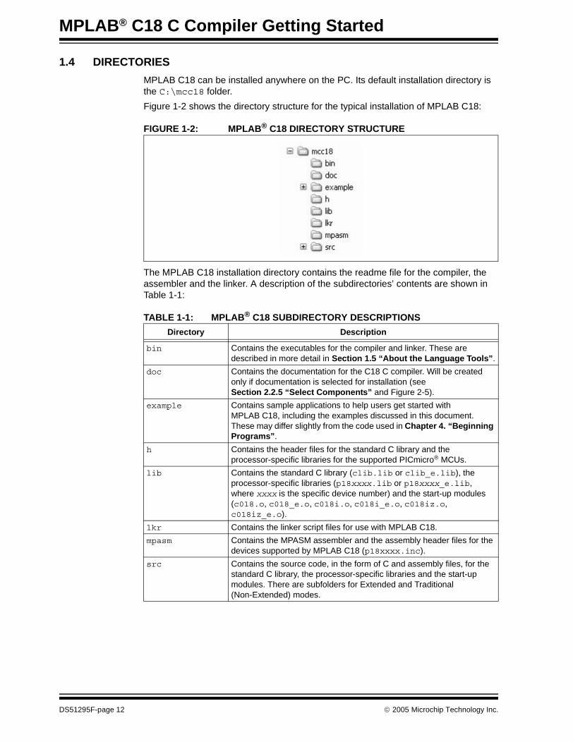
Figure 1-2 shows the directory structure for the typical installation of MPLAB C18:
FIGURE 1-2: MPLAB® C18 DIRECTORY STRUCTURE
The MPLAB C18 installation directory contains the readme file for the compiler, the assembler and the linker. A description of the subdirectories’ contents are shown in Table 1-1:
TABLE 1-1: MPLAB® C18 SUBDIRECTORY DESCRIPTIONS
Directory Description
bin Contains the executables for the compiler and linker. These are described in more detail in Section 1.5 “About the Language Tools”.
doc Contains the documentation for the C18 C compiler. Will be created only if documentation is selected for installation (see Section 2.2.5 “Select Components” and Figure 2-5).
example Contains sample applications to help users get started with MPLAB C18, including the examples discussed in this document. These may differ slightly from the code used in Chapter 4. “Beginning Programs”.
h Contains the header files for the standard C library and the processor-specific libraries for the supported PICmicro® MCUs.
lib Contains the standard C library (clib.lib or clib_e.lib), the processor-specific libraries (p18xxxx.lib or p18xxxx_e.lib, where xxxx is the specific device number) and the start-up modules (c018.o, c018_e.o, c018i.o, c018i_e.o, c018iz.o, c018iz_e.o).
lkr Contains the linker script files for use with MPLAB C18.
mpasm Contains the MPASM assembler and the assembly header files for the devices supported by MPLAB C18 (p18xxxx.inc).
src Contains the source code, in the form of C and assembly files, for the standard C library, the processor-specific libraries and the start-up modules. There are subfolders for Extended and Traditional (Non-Extended) modes.
DS51295F-page 12 © 2005 Microchip Technology Inc.
Overview
1.5 ABOUT THE LANGUAGE TOOLS
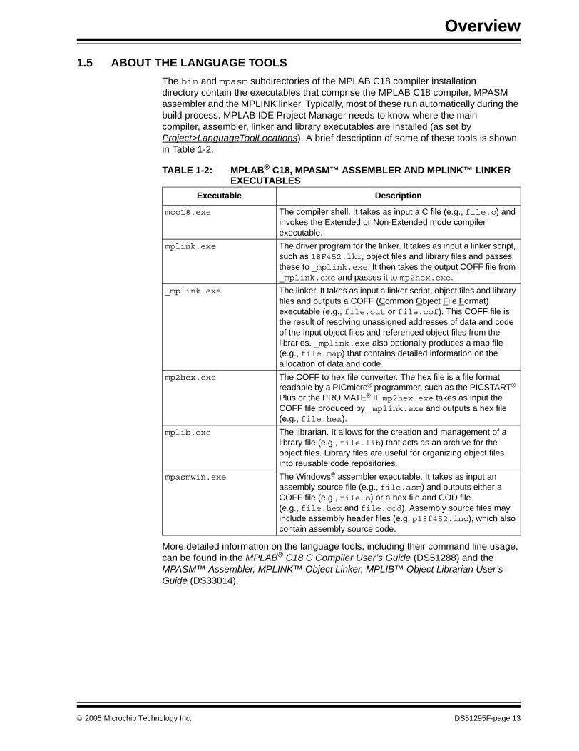
The bin and mpasm subdirectories of the MPLAB C18 compiler installation directory contain the executables that comprise the MPLAB C18 compiler, MPASM assembler and the MPLINK linker. Typically, most of these run automatically during the build process. MPLAB IDE Project Manager needs to know where the main compiler, assembler, linker and library executables are installed (as set by Project>LanguageToolLocations). A brief description of some of these tools is shown in Table 1-2.
More detailed information on the language tools, including their command line usage, can be found in the MPLAB® C18 C Compiler User’s Guide (DS51288) and the MPASM™ Assembler, MPLINK™ Object Linker, MPLIB™ Object Librarian User’s Guide (DS33014).
TABLE 1-2: MPLAB® C18, MPASM™ ASSEMBLER AND MPLINK™ LINKER EXECUTABLES
Executable Description
mcc18.exe The compiler shell. It takes as input a C file (e.g., file.c) and invokes the Extended or Non-Extended mode compiler executable.
mplink.exe The driver program for the linker. It takes as input a linker script, such as 18F452.lkr, object files and library files and passes these to _mplink.exe. It then takes the output COFF file from _mplink.exe and passes it to mp2hex.exe.
_mplink.exe The linker. It takes as input a linker script, object files and library files and outputs a COFF (Common Object File Format) executable (e.g., file.out or file.cof). This COFF file is the result of resolving unassigned addresses of data and code of the input object files and referenced object files from the libraries. _mplink.exe also optionally produces a map file (e.g., file.map) that contains detailed information on the allocation of data and code.
mp2hex.exe The COFF to hex file converter. The hex file is a file format readable by a PICmicro® programmer, such as the PICSTART® Plus or the PRO MATE® II. mp2hex.exe takes as input the COFF file produced by _mplink.exe and outputs a hex file (e.g., file.hex).
mplib.exe The librarian. It allows for the creation and management of a library file (e.g., file.lib) that acts as an archive for the object files. Library files are useful for organizing object files into reusable code repositories.
mpasmwin.exe The Windows® assembler executable. It takes as input an assembly source file (e.g., file.asm) and outputs either a COFF file (e.g., file.o) or a hex file and COD file (e.g., file.hex and file.cod). Assembly source files may include assembly header files (e.g, p18f452.inc), which also contain assembly source code.
© 2005 Microchip Technology Inc. DS51295F-page 13

MPLAB® C18 C Compiler Getting Started
1.6 EXECUTION FLOW
An example of the flow of execution of the language tools is illustrated in Figure 1-3.
FIGURE 1-3: LANGUAGE TOOLS EXECUTION FLOW
In the above example, two C files are compiled by MPLAB C18, file2.c and file3.c, and an assembly file, file1.asm, is assembled by MPASM. These result in object files, named file1.o, file2.o and file3.o.
A precompiled object file, file4.o, is used with file3.o to form a library called lib1.lib. Finally, the remaining object files are combined with the library file by the linker.
MPLINK also has as an input linker script, script.lkr. MPLINK produces the output files, output.cof and output.map, and the HEX file, output.hex.
MPASMWIN
MPLIB
MPLINK
MCC18 MCC18
InputSourceFiles
ObjectFiles
Libraryand
LinkerScriptFiles
OutputFiles
output.hexoutput.mapoutput.cof
lib1.lib script.lkr
file1.o file2.o file3.o file4.o
file1.asm file2.c file3.c
™
™
DS51295F-page 14 © 2005 Microchip Technology Inc.

MPLAB® C18 C COMPILER
GETTING STARTEDChapter 2. Installation
2.1 INTRODUCTION
MPLAB IDE should be installed on the PC prior to installing MPLAB C18. MPLAB IDE is provided on CD-ROM and is available from www.microchip.com at no charge. The project manager for MPLAB IDE and the MPLAB SIM simulator are both components of MPLAB IDE and, along with the built-in debugger, are used extensively in this guide (see Section 1.3 “System Requirements”).
This chapter discusses in detail the installation of MPLAB C18. Should it become necessary to remove the software, uninstall directions are provided.
2.2 INSTALLING MPLAB C18
To install MPLAB C18, run the installation program from the CD-ROM. If installing an MPLAB C18 upgrade, run the upgrade installation program downloaded from the Microchip web site. A series of dialogs step through the setup process.
2.2.1 Welcome
A welcome screen (Figure 2-1) displays the version number of MPLAB C18 that the installation program will install.
FIGURE 2-1: INSTALLATION: WELCOME SCREEN
Click Next> to continue.
Needs
Upd
ating
© 2005 Microchip Technology Inc. DS51295F-page 15
MPLAB® C18 C Compiler Getting Started
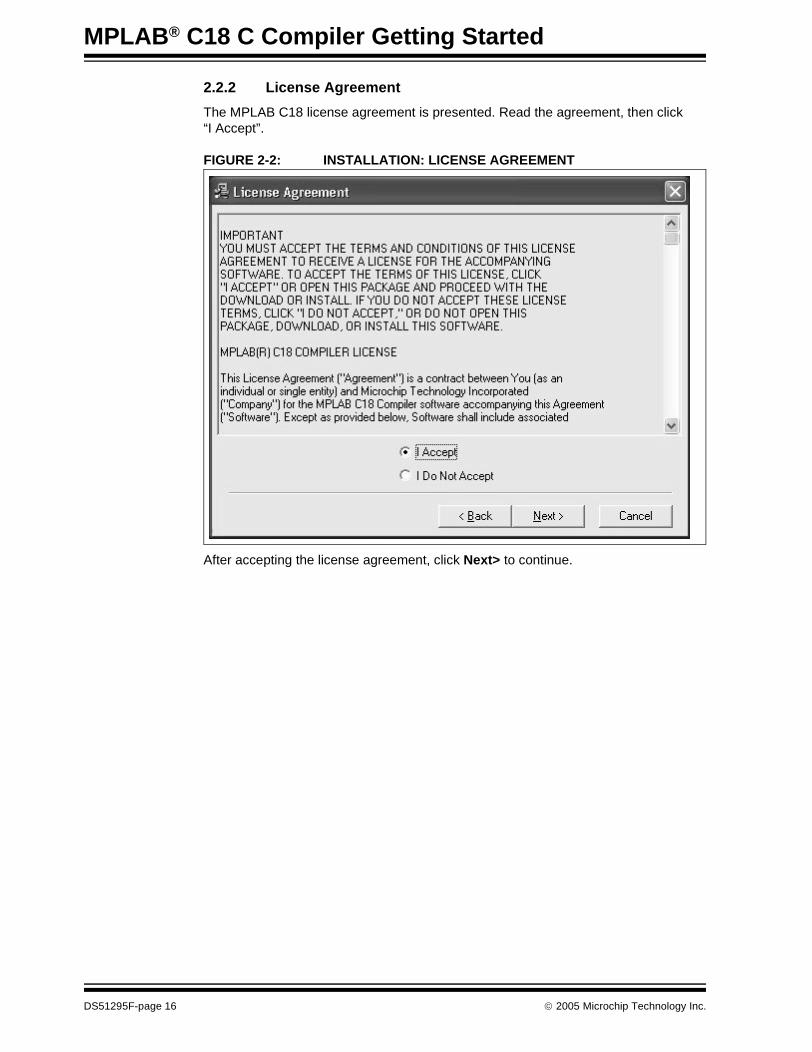
2.2.2 License Agreement
The MPLAB C18 license agreement is presented. Read the agreement, then click “I Accept”.
FIGURE 2-2: INSTALLATION: LICENSE AGREEMENT
After accepting the license agreement, click Next> to continue.
DS51295F-page 16 © 2005 Microchip Technology Inc.
Installation
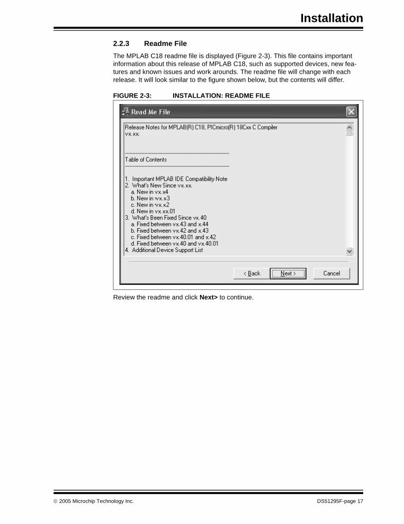
2.2.3 Readme File
The MPLAB C18 readme file is displayed (Figure 2-3). This file contains important information about this release of MPLAB C18, such as supported devices, new fea-tures and known issues and work arounds. The readme file will change with each release. It will look similar to the figure shown below, but the contents will differ.
FIGURE 2-3: INSTALLATION: README FILE
Review the readme and click Next> to continue.
© 2005 Microchip Technology Inc. DS51295F-page 17
MPLAB® C18 C Compiler Getting Started
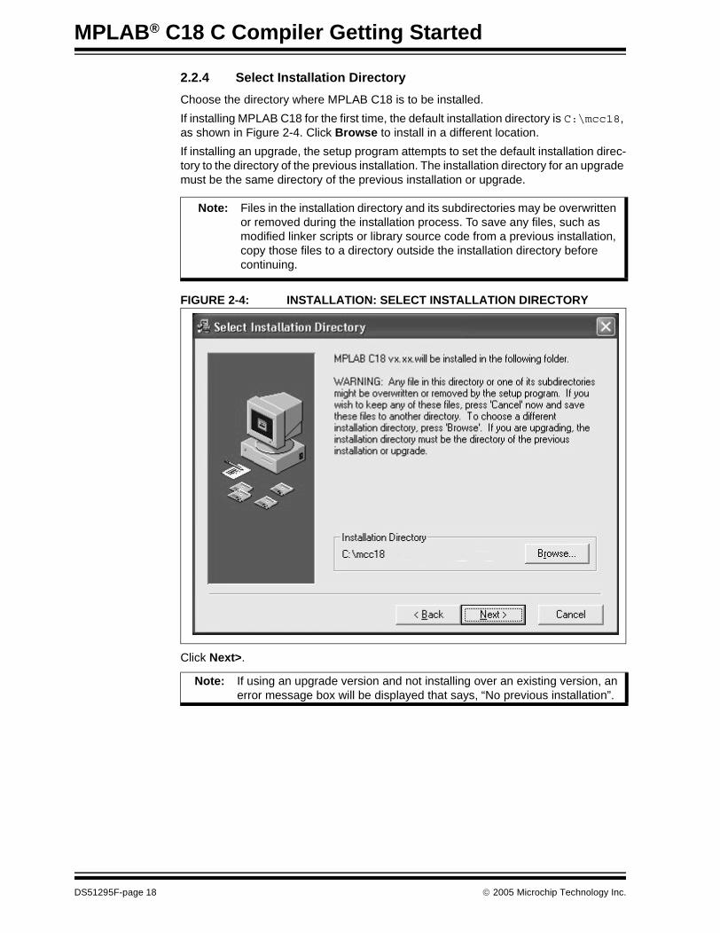
2.2.4 Select Installation Directory
Choose the directory where MPLAB C18 is to be installed.
If installing MPLAB C18 for the first time, the default installation directory is C:\mcc18, as shown in Figure 2-4. Click Browse to install in a different location.
If installing an upgrade, the setup program attempts to set the default installation direc-tory to the directory of the previous installation. The installation directory for an upgrade must be the same directory of the previous installation or upgrade.
FIGURE 2-4: INSTALLATION: SELECT INSTALLATION DIRECTORY
Click Next>.
Note: Files in the installation directory and its subdirectories may be overwritten or removed during the installation process. To save any files, such as modified linker scripts or library source code from a previous installation, copy those files to a directory outside the installation directory before continuing.
Note: If using an upgrade version and not installing over an existing version, an error message box will be displayed that says, “No previous installation”.
DS51295F-page 18 © 2005 Microchip Technology Inc.

Installation
2.2.5 Select Components
Choose the components to be installed by checking the appropriate boxes (Figure 2-5). Table 2-1 provides a detailed description of the available components.
There are linker scripts for MPASM provided with MPLAB IDE. Make sure to use the linker scripts that are installed with MPLAB C18, not those that were installed with MPLAB IDE when using the MPLAB C18 compiler. The linker scripts provided with MPLAB C18 have some special directives for the compiler.
FIGURE 2-5: INSTALLATION: SELECT COMPONENTS
Click Next> to continue.
Note: MPASM and MPLINK are provided free with MPLAB IDE. They are also included in the MPLAB C18 compiler installation. To ensure compatibility between all tools, the versions of MPASM and MPLINK provided with the MPLAB C18 compiler should be used.
Note: Not all installations include documentation. Upgrades and some web downloads have documentation distributed separately.
© 2005 Microchip Technology Inc. DS51295F-page 19
MPLAB® C18 C Compiler Getting Started
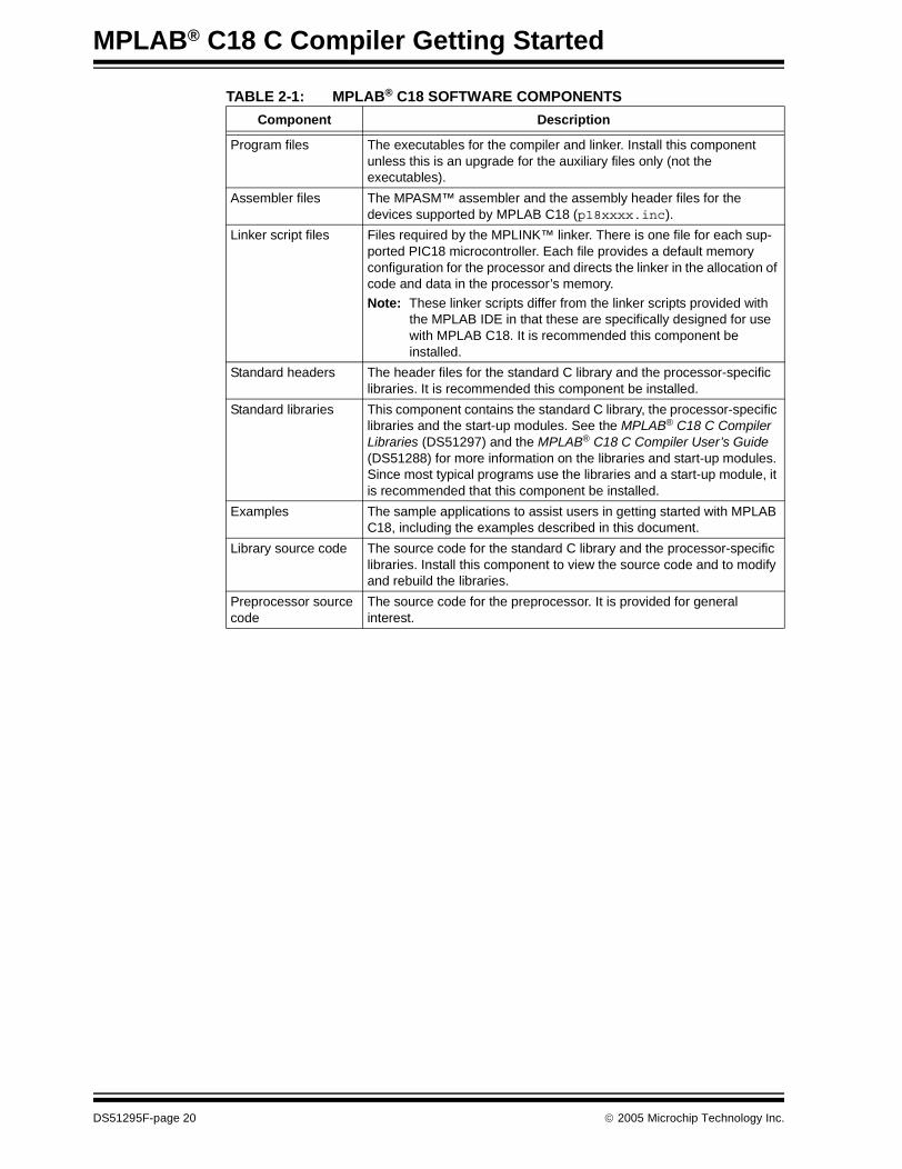
TABLE 2-1: MPLAB® C18 SOFTWARE COMPONENTS
Component Description
Program files The executables for the compiler and linker. Install this component unless this is an upgrade for the auxiliary files only (not the executables).
Assembler files The MPASM™ assembler and the assembly header files for the devices supported by MPLAB C18 (p18xxxx.inc).
Linker script files Files required by the MPLINK™ linker. There is one file for each sup-ported PIC18 microcontroller. Each file provides a default memory configuration for the processor and directs the linker in the allocation of code and data in the processor’s memory.
Note: These linker scripts differ from the linker scripts provided with the MPLAB IDE in that these are specifically designed for use with MPLAB C18. It is recommended this component be installed.
Standard headers The header files for the standard C library and the processor-specific libraries. It is recommended this component be installed.
Standard libraries This component contains the standard C library, the processor-specific libraries and the start-up modules. See the MPLAB® C18 C Compiler Libraries (DS51297) and the MPLAB® C18 C Compiler User’s Guide (DS51288) for more information on the libraries and start-up modules. Since most typical programs use the libraries and a start-up module, it is recommended that this component be installed.
Examples The sample applications to assist users in getting started with MPLAB C18, including the examples described in this document.
Library source code The source code for the standard C library and the processor-specific libraries. Install this component to view the source code and to modify and rebuild the libraries.
Preprocessor source code
The source code for the preprocessor. It is provided for general interest.
DS51295F-page 20 © 2005 Microchip Technology Inc.
Installation
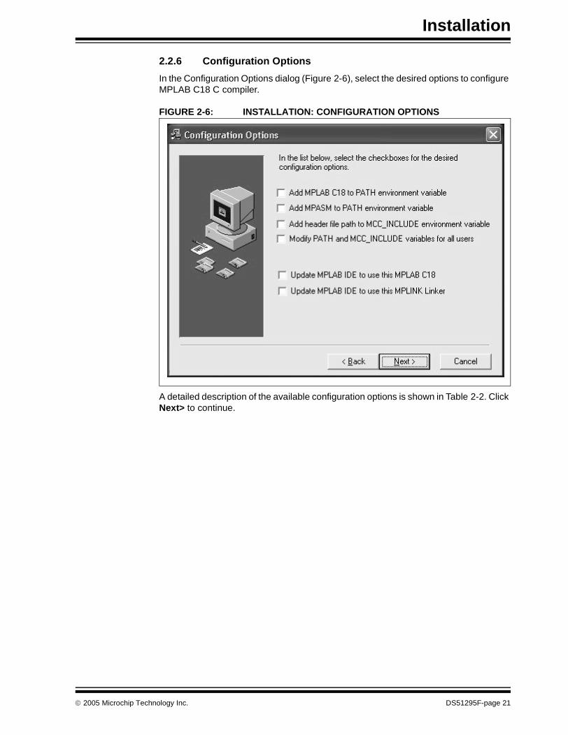
2.2.6 Configuration Options
In the Configuration Options dialog (Figure 2-6), select the desired options to configure MPLAB C18 C compiler.
FIGURE 2-6: INSTALLATION: CONFIGURATION OPTIONS
A detailed description of the available configuration options is shown in Table 2-2. Click Next> to continue.
© 2005 Microchip Technology Inc. DS51295F-page 21
MPLAB® C18 C Compiler Getting Started
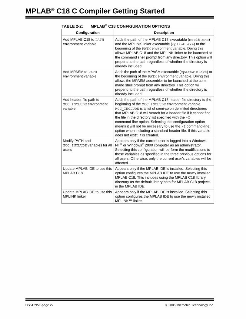
TABLE 2-2: MPLAB® C18 CONFIGURATION OPTIONS
Configuration Description
Add MPLAB C18 to PATH environment variable
Adds the path of the MPLAB C18 executable (mcc18.exe) and the MPLINK linker executable (mplink.exe) to the beginning of the PATH environment variable. Doing this allows MPLAB C18 and the MPLINK linker to be launched at the command shell prompt from any directory. This option will prepend to the path regardless of whether the directory is already included.
Add MPASM to PATHenvironment variable
Adds the path of the MPASM executable (mpasmwin.exe) to the beginning of the PATH environment variable. Doing this allows the MPASM assembler to be launched at the com-mand shell prompt from any directory. This option will prepend to the path regardless of whether the directory is already included.
Add header file path to MCC_INCLUDE environmentvariable
Adds the path of the MPLAB C18 header file directory to the beginning of the MCC_INCLUDE environment variable. MCC_INCLUDE is a list of semi-colon delimited directories that MPLAB C18 will search for a header file if it cannot find the file in the directory list specified with the -I command-line option. Selecting this configuration option means it will not be necessary to use the -I command-line option when including a standard header file. If this variable does not exist, it is created.
Modify PATH and MCC_INCLUDE variables for all users
Appears only if the current user is logged into a Windows NT® or Windows® 2000 computer as an administrator. Selecting this configuration will perform the modifications to these variables as specified in the three previous options for all users. Otherwise, only the current user’s variables will be affected.
Update MPLAB IDE to use this MPLAB C18
Appears only if the MPLAB IDE is installed. Selecting this option configures the MPLAB IDE to use the newly installed MPLAB C18. This includes using the MPLAB C18 library directory as the default library path for MPLAB C18 projects in the MPLAB IDE.
Update MPLAB IDE to use this MPLINK linker
Appears only if the MPLAB IDE is installed. Selecting this option configures the MPLAB IDE to use the newly installed MPLINK™ linker.
DS51295F-page 22 © 2005 Microchip Technology Inc.

Installation
2.2.7 Documentation Notice
If documentation is not included with the executables, a notification similar to Figure 2-7 will be displayed. Documentation is available on the MPLAB C18 Installation CD-ROM and the Microchip web site.
FIGURE 2-7: INSTALLATION: UPDATE DOCUMENTATION REMINDER
2.2.8 Start Installation
At the Start Installation screen (Figure 2-8), click Next> to install the files.
Note: To install documentation automatically using either the MPLAB C18 CD-ROM or an upgrade (with documentation) from the web site, select the Documentation option on the Select Components dialog (see Figure 2-5).
Note: Any files in the installation directory and its subdirectories will be overwritten or removed.
© 2005 Microchip Technology Inc. DS51295F-page 23

MPLAB® C18 C Compiler Getting Started
FIGURE 2-8: INSTALLATION: START INSTALLATION
2.2.9 Complete Installation
At the Installation Complete screen, click Finish. MPLAB C18 has been successfully installed.
It may be necessary to restart the computer for MPLAB C18 to operate properly. If the Restart Computer dialog displays, select Yes to restart immediately, or No to restart the computer at a later time.
2.3 UNINSTALLING MPLAB C18
To uninstall MPLAB C18, open the Windows control panel and launch Add/Remove Programs. Select the MPLAB C18 installation in the list of programs and follow the directions to remove the program. This will remove the MPLAB C18 directory and its contents from the computer.
Note: If uninstalling an upgraded version of MPLAB C18, the entire installation will be removed. MPLAB C18 cannot be downgraded to a previously installed version. Make sure that the original installation CD is available before choosing to remove an upgraded version so that MPLAB C18 may be re-installed at a later time.
DS51295F-page 24 © 2005 Microchip Technology Inc.

MPLAB® C18 C COMPILER
GETTING STARTEDChapter 3. Project Basics and MPLAB IDE Configuration
3.1 INTRODUCTION
This section covers the basics of MPLAB projects and configuration options for testing the examples and applications in this guide with MPLAB SIM. This is intended as an overview and covers a generic application. Details on such things as device selection and linker scripts will vary with applications. This chapter can be skipped if these basic operations are known.
Topics covered in this chapter are:
• Project Overview• Creating a File• Creating Projects• Using the Project Window• Configuring Language Tool Locations• Verify Installation and Build Options• Building and Testing
3.2 PROJECT OVERVIEW
Projects are groups of files associated with language tools, such as MPLAB C18, in the MPLAB IDE. A project consists of source files, header files, object files, library files and a linker script. Every project should have one or more source files and one linker script.
Typically, at least one header file is required to identify the register names of the target microcontroller. Header files are typically included by source files and are not explicitly added to the project.
The project’s output files consist of executable code to be loaded into the target micro-controller as firmware. Debugging files are generated to help MPLAB IDE correlate the symbols and function names from the source files with the executable code and memory used for variable storage.
Most examples and applications in this guide consist of a project with only one source file and one linker script.
For additional information, refer to the MPLAB® IDE Quick Start Guide (DS51281).
Note: This is not a step-by-step procedure to create and build a project, but an overview and a checklist to ensure that MPLAB IDE is set up correctly. The MPLAB IDE User’s Guide has a tutorial for creating projects.
© 2005 Microchip Technology Inc. DS51295F-page 25
MPLAB® C18 C Compiler Getting Started
3.3 CREATING A FILE
Start MPLAB IDE and select File>New to bring up a new empty source file. The examples and applications in this guide list source code that can be typed in, or copied and pasted into a text file using the MPLAB editor. Find example source in mcc18\example\getting started.
Type or copy the source text (as listed in each example in this manual) into this new file. (Text copied from examples in this document may not preserve white space.) Use File>Save As to save this file. Browse to or create a new folder location to store projects. Click Save.
3.4 CREATING PROJECTS
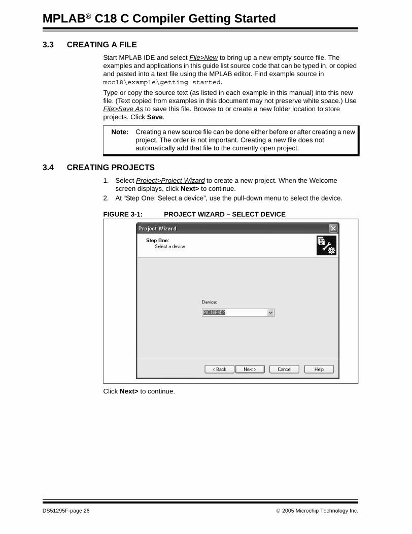
1. Select Project>Project Wizard to create a new project. When the Welcome screen displays, click Next> to continue.
2. At “Step One: Select a device”, use the pull-down menu to select the device.
FIGURE 3-1: PROJECT WIZARD – SELECT DEVICE
Click Next> to continue.
Note: Creating a new source file can be done either before or after creating a new project. The order is not important. Creating a new file does not automatically add that file to the currently open project.
DS51295F-page 26 © 2005 Microchip Technology Inc.

Project Basics and MPLAB IDE Configuration
3. At “Step Two: Select a language toolsuite”, choose “Microchip C18 Toolsuite” as the “Active Toolsuite”. Then click on each language tool in the toolsuite (under “Toolsuite Contents”) and check or set up its associated executable location (Figure 3-2).
FIGURE 3-2: PROJECT WIZARD – SELECT LANGUAGE TOOLSUITE
MPASM Assembler should point to the assembler executable, MPASMWIN.exe, under “Location”. If it does not, enter or browse to the executable location, which is by default: C:\mcc18\mpasm\MPASMWIN.exe
MPLAB C18 C Compiler should point to the compiler executable, mcc18.exe, under “Location”. If it does not, enter or browse to the executable location, which is by default:C:\mcc18\bin\mcc18.exe
MPLINK Object Linker should point to the linker executable, MPLink.exe, under “Location”. If it does not, enter or browse to the executable location, which is by default:C:\mcc18\bin\MPLink.exe
MPLIB Librarian should point to the library executable, MPLib.exe, under “Location”. If it does not, enter or browse to the executable location, which is by default:C:\mcc18\bin\MPLib.exe
Click Next> to continue.
© 2005 Microchip Technology Inc. DS51295F-page 27

MPLAB® C18 C Compiler Getting Started
4. At “Step Three: Name your project” (Figure 3-3), enter the name of the project and use Browse to select the folder where the project will be saved. Then click Next> to continue.
FIGURE 3-3: PROJECT WIZARD – PROJECT NAME AND DIRECTORY
5. At “Step Four: Add any existing files to your project”, navigate to the source file to be added to the project.
First, select the source file created earlier. If source files have not yet been created, they can be added later (see Figure 3-4). Click ADD>> to add it to the list of files to be used for this project (on the right).
FIGURE 3-4: PROJECT WIZARD – ADD C SOURCE FILE
DS51295F-page 28 © 2005 Microchip Technology Inc.
Project Basics and MPLAB IDE Configuration
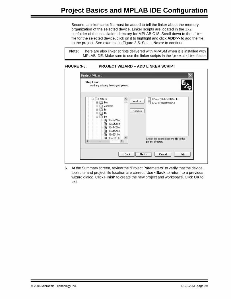
Second, a linker script file must be added to tell the linker about the memory organization of the selected device. Linker scripts are located in the lkr subfolder of the installation directory for MPLAB C18. Scroll down to the .lkr file for the selected device, click on it to highlight and click ADD>> to add the file to the project. See example in Figure 3-5. Select Next> to continue.
FIGURE 3-5: PROJECT WIZARD – ADD LINKER SCRIPT
6. At the Summary screen, review the “Project Parameters” to verify that the device, toolsuite and project file location are correct. Use <Back to return to a previous wizard dialog. Click Finish to create the new project and workspace. Click OK to exit.
Note: There are also linker scripts delivered with MPASM when it is installed with MPLAB IDE. Make sure to use the linker scripts in the \mcc18\lkr folder.
© 2005 Microchip Technology Inc. DS51295F-page 29

MPLAB® C18 C Compiler Getting Started
3.5 USING THE PROJECT WINDOW
Locate the project window on the MPLAB IDE workspace. The file name of the work-space should appear in the top title bar of the project window with the file name as the top node in the project. The project should look similar to Figure 3-6.
FIGURE 3-6: PROJECT WINDOW
3.6 CONFIGURING LANGUAGE TOOL LOCATIONS
This section shows how to set default locations for MPLAB projects. Creating defaults enables them to be easily applied to new projects. These defaults can also be selected or changed once a project is created.
Selecting the language tool locations is done through the MPLAB IDE program. Launch MPLAB IDE to begin.
Select Project>Set Language Tool Locations to open the Set Language Tool Locations dialog. Click the “plus” sign next to the Microchip C18 Toolsuite to expand it, then scroll down and expand the executables. Click on each of the executables in the expanded list to verify that it is properly installed as shown in the Location box.
Note: If an error was made, highlight a file name and press the Delete key or use the right mouse menu to delete a file. Place the cursor over “Source Files” or “Linker Scripts” and use the right mouse menu to add the proper files to the project.
DS51295F-page 30 © 2005 Microchip Technology Inc.

Project Basics and MPLAB IDE Configuration
For MPASM Assembler, verify its location is C:\mcc18\mpasm\MPASMWIN.exe as shown in Figure 3-7.
FIGURE 3-7: SET LANGUAGE TOOL LOCATIONS: MPASM™ ASSEMBLER
For MPLAB C18 compiler executable, verify its location is C:\mcc18\bin\mcc18.exe as shown in Figure 3-8.
FIGURE 3-8: SET LANGUAGE TOOL LOCATIONS: MPLAB® C18
© 2005 Microchip Technology Inc. DS51295F-page 31

MPLAB® C18 C Compiler Getting Started
For MPLIB Librarian (part of the compiler package executables), verify its location is C:\mcc18\bin\MPLib.exe as shown in Figure 3-9.
FIGURE 3-9: SET LANGUAGE TOOL LOCATIONS: MPLIB™ LIBRARIAN
And for the MPLINK Linker, ensure that its location is C:\mcc18\bin\MPLink.exe as shown in Figure 3-10.
FIGURE 3-10: SET LANGUAGE TOOL LOCATIONS: MPLINK™ LINKER
Click OK to save these settings and close this dialog.
DS51295F-page 32 © 2005 Microchip Technology Inc.

Project Basics and MPLAB IDE Configuration
3.7 VERIFY INSTALLATION AND BUILD OPTIONS
Before proceeding with compiling and testing programs, the installation and project settings should be verified.
The language tools should be installed correctly and the settings should be appropriate for these first examples of code, otherwise errors may result. Follow through with these checks:
1. Select the Project>Build Options...>Project, and click on the General tab. If the Include Path and the Library Path are not set as shown in Figure 3-11, use the Browse button to locate these folders in the MPLAB C18 installation folder.
FIGURE 3-11: BUILD OPTIONS: GENERAL
Note: Multiple paths can be entered for a single include or library search path by separating them with a semicolon: c:\myprojects\h;c:\mcc18\h.
© 2005 Microchip Technology Inc. DS51295F-page 33

MPLAB® C18 C Compiler Getting Started
2. One option may need to be changed from the default. Click on the MPLINK Linker tab. If it is not checked, click on the box labeled Suppress COD-file generation:
FIGURE 3-12: BUILD OPTIONS: MPLINK™ LINKER
Click OK to close this dialog.
Note: If this box is not checked, the linker will also generate an older .cod file type, which is no longer used by MPLAB IDE. This file format has a file/path length limitation of 62 characters which will cause this error: “name exceeds file format maximum of 62 characters”.
DS51295F-page 34 © 2005 Microchip Technology Inc.

Project Basics and MPLAB IDE Configuration
3.8 BUILDING AND TESTING
3.8.1 Build Project
If everything is installed as instructed, the project can be built using the menu selection Project>Build All or Project>Make.
Shortcut keys, Ctrl+F10 and F10, can be used instead of selecting items from the menu. There are icons on the toolbar for these functions as well, so either one function key or one mouse click will build the project:
FIGURE 3-13: BUILD ALL AND MAKE ICONS
The project should build correctly as seen in the Output window:
FIGURE 3-14: OUTPUT WINDOW AFTER SUCCESSFUL BUILD
If the message “Errors : 0” is not shown from both MPLINK (the Linker) and MP2HEX (the .hex file converter), something may have been mistyped. Expand the Output window and look for the first error. If it was a mistype, then double click on that error line in the Output window to edit the error in the file main.c. If there was some other error, see Chapter 7. “Troubleshooting”.
Note: Compiling and linking all the files in a project is called a “make” or a “build”. Build All will recompile all source files in a project, while Make will only recompile those that have changed since the last build, usually resulting in a faster build, especially if projects have many source files.
Note: By moving the cursor over these icons, a pop-up will identify their function.
© 2005 Microchip Technology Inc. DS51295F-page 35
MPLAB® C18 C Compiler Getting Started
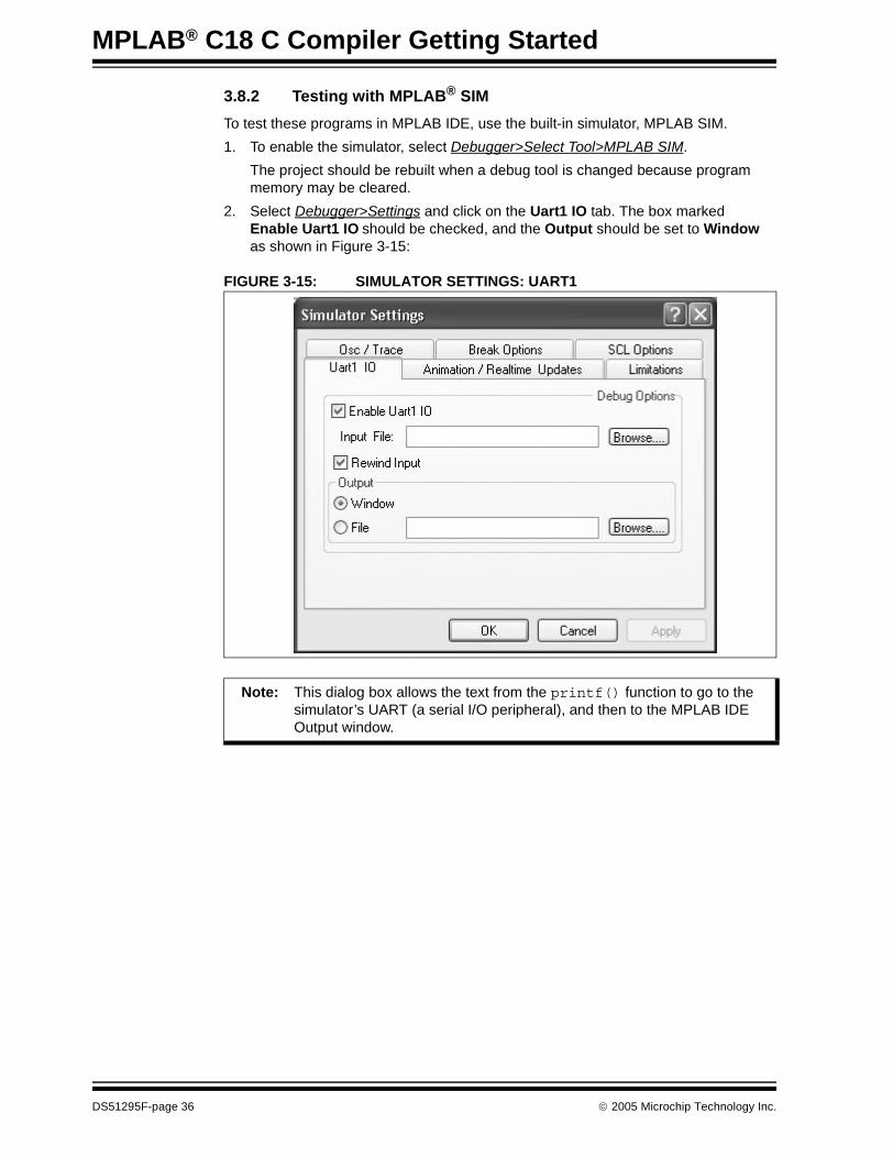
3.8.2 Testing with MPLAB® SIM
To test these programs in MPLAB IDE, use the built-in simulator, MPLAB SIM.
1. To enable the simulator, select Debugger>Select Tool>MPLAB SIM.
The project should be rebuilt when a debug tool is changed because program memory may be cleared.
2. Select Debugger>Settings and click on the Uart1 IO tab. The box marked Enable Uart1 IO should be checked, and the Output should be set to Window as shown in Figure 3-15:
FIGURE 3-15: SIMULATOR SETTINGS: UART1
Note: This dialog box allows the text from the printf() function to go to the simulator’s UART (a serial I/O peripheral), and then to the MPLAB IDE Output window.
DS51295F-page 36 © 2005 Microchip Technology Inc.

Project Basics and MPLAB IDE Configuration
After the simulator is selected, the Debug Toolbar (Figure 3-16) appears under the MPLAB menus.
FIGURE 3-16: DEBUG TOOLBAR
See the MPLAB® IDE User’s Guide for more information on projects, MPLAB configuration and extended debugging techniques.
Icon Function
Run Run program
Halt Halt program execution
Animate Continually step into instructions. To Halt, use Debugger>Halt or press the Halt icon.
Step Into Step into the next instruction
Step Over Step over the next instruction
Step Out Step out of the subroutine
Reset Perform a MCLR Reset
© 2005 Microchip Technology Inc. DS51295F-page 37

MPLAB® C18 C Compiler Getting Started
NOTES:
DS51295F-page 38 © 2005 Microchip Technology Inc.

MPLAB® C18 C COMPILER
GETTING STARTEDChapter 4. Beginning Programs
4.1 INTRODUCTION
It is assumed that the reader is familiar with MPLAB projects. A quick overview is available in Chapter 3. “Project Basics and MPLAB IDE Configuration”. A more thorough description is in the MPLAB® IDE User’s Guide.
The following sections present three beginning programs to familiarize the engineer or student with MPLAB C18 C Compiler using the MPLAB Integrated Development Environment.
• Program 1: “Hello, world!” – prints the text “Hello, world!”• Program 2: Light LED Using Simulator – writes to an I/O pin on a simulated PIC18
device to turn on an indicator light. • Program 3: Flash LED Using Simulator – extends the second program to flash the
light on and off.• Using the Demo Board – demonstrates how to test using a demo board.
If MPLAB ICD 2 and development hardware are available, the previous program will be compiled to be debugged under MPLAB ICD 2 with the development board to flash real LEDs.
4.2 PROGRAM 1: “HELLO, WORLD!”
4.2.1 Write the Source Code
The typical “Hello, world!” function contains this C statement to print out a message:
printf ("Hello, world!\n");
The function main() is written like Example 4-1:
EXAMPLE 4-1: HELLO, WORLD! main() CODEvoid main (void){ printf ("Hello, world!\n");
while (1) ;}
Note: Often, the final “while (1)” statement is not used for the “Hello, world!” program because the example compiles on a PC, executes, then returns back to the operating system and to other tasks. In the case of an embed-ded controller, however, the target microcontroller continues running and must do something, so in this example, an infinite loop keeps the microcontroller busy after doing its single task of printing out “Hello, world!”.
© 2005 Microchip Technology Inc. DS51295F-page 39
MPLAB® C18 C Compiler Getting Started
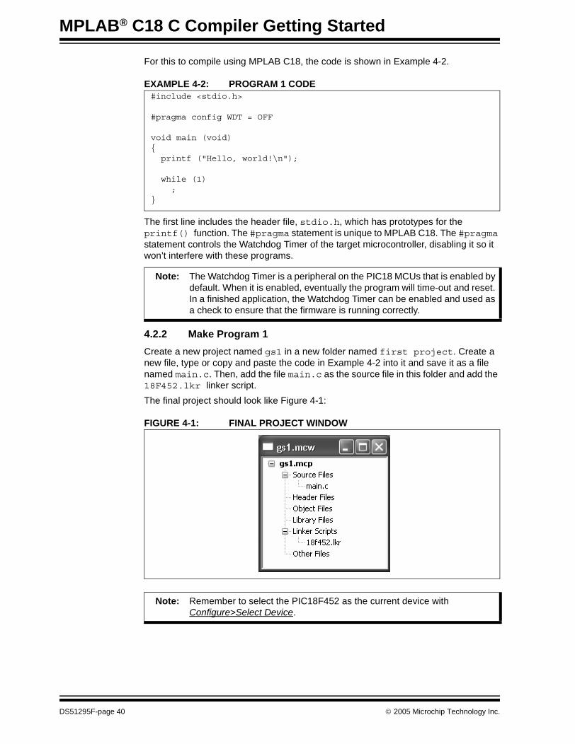
For this to compile using MPLAB C18, the code is shown in Example 4-2.
EXAMPLE 4-2: PROGRAM 1 CODE
The first line includes the header file, stdio.h, which has prototypes for the printf() function. The #pragma statement is unique to MPLAB C18. The #pragma statement controls the Watchdog Timer of the target microcontroller, disabling it so it won’t interfere with these programs.
4.2.2 Make Program 1
Create a new project named gs1 in a new folder named first project. Create a new file, type or copy and paste the code in Example 4-2 into it and save it as a file named main.c. Then, add the file main.c as the source file in this folder and add the 18F452.lkr linker script.
The final project should look like Figure 4-1:
FIGURE 4-1: FINAL PROJECT WINDOW
#include <stdio.h>
#pragma config WDT = OFF
void main (void){ printf ("Hello, world!\n");
while (1) ;}
Note: The Watchdog Timer is a peripheral on the PIC18 MCUs that is enabled by default. When it is enabled, eventually the program will time-out and reset. In a finished application, the Watchdog Timer can be enabled and used as a check to ensure that the firmware is running correctly.
Note: Remember to select the PIC18F452 as the current device with Configure>Select Device.
DS51295F-page 40 © 2005 Microchip Technology Inc.
Beginning Programs
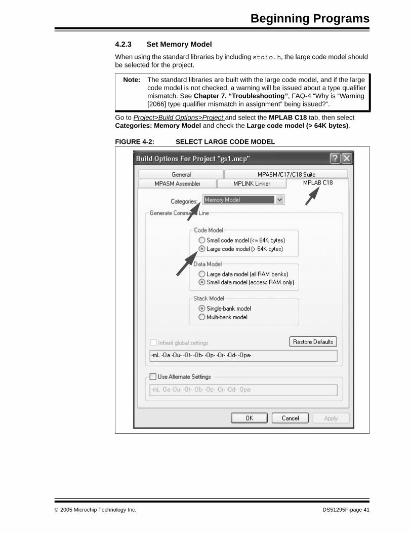
4.2.3 Set Memory Model
When using the standard libraries by including stdio.h, the large code model should be selected for the project.
Go to Project>Build Options>Project and select the MPLAB C18 tab, then select Categories: Memory Model and check the Large code model (> 64K bytes).
FIGURE 4-2: SELECT LARGE CODE MODEL
Note: The standard libraries are built with the large code model, and if the large code model is not checked, a warning will be issued about a type qualifier mismatch. See Chapter 7. “Troubleshooting”, FAQ-4 “Why is “Warning [2066] type qualifier mismatch in assignment” being issued?”.
© 2005 Microchip Technology Inc. DS51295F-page 41

MPLAB® C18 C Compiler Getting Started
4.2.4 Test Program 1
Use Project>Build All or the equivalent icon to build the project.
After a successful build, the Run icon becomes blue, indicating that the program is halted and ready to run. Select the Run icon and it turns gray, indicating it is running. The Halt icon turns blue, indicating the program is running and can be halted. In addi-tion, on the status bar at the bottom is a “Running...” indicator. Select the Halt icon and open the Output window if it is not already open (Figure 4-3).
FIGURE 4-3: OUTPUT WINDOW: “HELLO, WORLD!”
The text, “Hello, world!”, should appear in the SIM Uart1 tab of the Output window.
Select the Reset icon to reset the program, and then select the Run icon again to print the message a second time in the Output window.
Note: After “Hello, world!” prints out, the program continues executing, running in an endless while (1) loop until it is halted. If Run is executed immedi-ately after halting, the endless loop resumes running. In order to re-execute the program from the beginning, select the Reset icon after the program is halted.
DS51295F-page 42 © 2005 Microchip Technology Inc.

Beginning Programs
4.2.5 Resolve Problems
If a mistype caused an error when building the project, the last lines in the Output window may look like Figure 4-4:
FIGURE 4-4: OUTPUT WINDOW SYNTAX ERROR
Double click on the line with “syntax error” to bring up the MPLAB Editor window with the cursor on the line with the syntax error (Figure 4-4).
An error that reads “could not find stdio.h” usually means that the include path is not set up. Refer to Section 3.7 “Verify Installation and Build Options” for information on setting up the include path.
A warning that reads “type qualifier mismatch in assignment” may mean that the large memory model is not selected when using standard I/O. Refer to Section 4.2.3 “Set Memory Model”.
An error that “c018i.o is not found” could mean that the library path is not set up correctly. Refer to Section 3.7 “Verify Installation and Build Options” for information on setting up the library path
If a message says it can not find a definition of “main” in c018i.o, make sure “main” is spelled all lower case since C is case-sensitive.
An error that reads “could not find definition of symbol...” is usually caused by using the wrong linker script:
Make sure that the 18F452.lkr file in the mcc18\lkr directory is used. MPLAB IDE also has a linker script for assembler-only projects in one of its subdirectories. Always use the mcc18\lkr linker scripts for all projects using the MPLAB C18 compiler.
If “Hello, world!” does not appear in the Output window, try these steps:
1. Make sure that the simulator is selected (Debugger>Select Tool>MPLAB SIM).2. Make sure the Uart1 is enabled to send printf() text to the MPLAB IDE
Output window as shown in Figure 3-15.3. Select the Halt icon (Figure 3-16).4. Build All again. There should be no errors in the Output window, and the
message “Build Succeeded” should appear as the last line (Figure 3-13).5. Select the Reset icon on the Debug Toolbar (Figure 3-16).6. Select the Run icon on the Debug Toolbar (Figure 3-16).
Note: To clear the Output window, right click the mouse button and select the Clear Page option.
© 2005 Microchip Technology Inc. DS51295F-page 43

MPLAB® C18 C Compiler Getting Started
4.2.6 Summary for Program 1 “Hello, world!”
This completes the first program example. These topics were covered:
• Writing MPLAB C18 code• Building (compiling and linking) the project• Testing the project with MPLAB SIM• Troubleshooting beginner errors
4.3 PROGRAM 2: LIGHT LED USING SIMULATOR
The first example demonstrated the basics of creating, building and testing a project using MPLAB C18 with the MPLAB IDE. It did not go into the details of what the target processor would do with that code. In this next program, code will be generated to simulate turning on a Light Emitting Diode (LED) connected to a pin of the PIC18F452.
4.3.1 Create a New Project
Create a new project named “GS2” in a new folder named “Second Project.”
Make sure the language tools are set up and the Build Options properly configured as shown in Section 3.7 “Verify Installation and Build Options”.
4.3.2 Write the Source Code
Create a new file and type in the code shown in Example 4-3. Save it with the name main.c in the “Second Project” folder:
EXAMPLE 4-3: PROGRAM 2 CODE: main.c
The first line in this code includes the generic processor header file for all PIC18XXXX devices, named p18cxxx.h. This file chooses the appropriate header file as selected in MPLAB IDE; in this case, the file named p18f542.h (which could have been included explicitly instead). This file contains the definitions for the Special Function Registers in these devices.
“#pragma config WDT = OFF” is the same as in the first program.
#include <p18cxxx.h>
#pragma config WDT = OFF
void main (void){ TRISB = 0;
/* Reset the LEDs */ PORTB = 0;
/* Light the LEDs */ PORTB = 0x5A;
while (1) ;}
Note: In MPLAB C18, the main function is declared as returning void, since embedded applications do not return to another operating system or function.
DS51295F-page 44 © 2005 Microchip Technology Inc.
Beginning Programs
This example will use four pins on the 8-bit I/O port with the register name PORTB.
“TRISB = 0” sets the PIC18F452 register named TRISB to a value of zero. The TRIS registers control the direction of the I/O pins on the ports. Port pins can be either inputs or outputs. Setting them all to zero will make all eight pins function as outputs.
“PORTB = 0” sets all eight pins of the PORTB register to ‘0’ or to a low voltage.
“PORTB = 0x5A” sets four pins on PORTB to ‘1’ or to a high voltage (0x5A = 0b01011010).
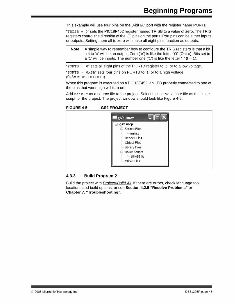
When this program is executed on a PIC18F452, an LED properly connected to one of the pins that went high will turn on.
Add main.c as a source file to the project. Select the 18F452.lkr file as the linker script for the project. The project window should look like Figure 4-5:
FIGURE 4-5: GS2 PROJECT
4.3.3 Build Program 2
Build the project with Project>Build All. If there are errors, check language tool locations and build options, or see Section 4.2.5 “Resolve Problems” or Chapter 7. “Troubleshooting”.
Note: A simple way to remember how to configure the TRIS registers is that a bit set to ‘0’ will be an output. Zero (‘0’) is like the letter “O” (O = 0). Bits set to a ‘1’ will be inputs. The number one (‘1’) is like the letter “I” (I = 1).
© 2005 Microchip Technology Inc. DS51295F-page 45

MPLAB® C18 C Compiler Getting Started
4.3.4 Test Program 2
Like in the first program, the simulator in MPLAB IDE will be used to test this code. Make sure that the simulator is enabled. The project may need to be built again if the simulator was not already selected.
To test the code, the state of the pins on PORTB must be monitored. In MPLAB IDE, there are a two ways to do this.
4.3.4.1 USING THE MOUSE OVER VARIABLE
After the project is successfully built, use the mouse to place the text editor cursor over a variable name in the editor window to show the current value of that variable. Before this program is run, a mouse over PORTB should show its value of zero (see Figure 4-6):
FIGURE 4-6: MOUSE OVER PORTB BEFORE PROGRAM EXECUTION
Click the Run icon (or select Debug>Run), then click the Halt icon and do the mouse over again. The value should now be 0x5A (Figure 4-7):
FIGURE 4-7: MOUSE OVER PORTB AFTER PROGRAM EXECUTION
DS51295F-page 46 © 2005 Microchip Technology Inc.

Beginning Programs
4.3.4.2 USING THE WATCH WINDOW
The second way to check the value of a variable is to put it into a Watch window. Select View>Watch to bring up a new Watch window (Figure 4-8).
FIGURE 4-8: NEW WATCH WINDOW
Now drag this Watch window away from the source file window so that it is not on top of any part of it. Highlight the word PORTB in main.c. When the word is highlighted, drag it to the empty area of the Watch window. The Watch window now looks like Figure 4-9.
FIGURE 4-9: WATCH WINDOW FOR PORTB
Note: If the value of PORTB shows 0x5A, the program was executed previously. Double click on the value in the Watch window and type zero to clear it.
© 2005 Microchip Technology Inc. DS51295F-page 47
MPLAB® C18 C Compiler Getting Started
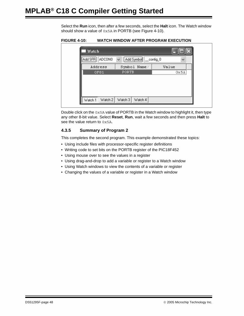
Select the Run icon, then after a few seconds, select the Halt icon. The Watch window should show a value of 0x5A in PORTB (see Figure 4-10).
FIGURE 4-10: WATCH WINDOW AFTER PROGRAM EXECUTION
Double click on the 0x5A value of PORTB in the Watch window to highlight it, then type any other 8-bit value. Select Reset, Run, wait a few seconds and then press Halt to see the value return to 0x5A.
4.3.5 Summary of Program 2
This completes the second program. This example demonstrated these topics:
• Using include files with processor-specific register definitions• Writing code to set bits on the PORTB register of the PIC18F452• Using mouse over to see the values in a register• Using drag-and-drop to add a variable or register to a Watch window• Using Watch windows to view the contents of a variable or register• Changing the values of a variable or register in a Watch window
DS51295F-page 48 © 2005 Microchip Technology Inc.

Beginning Programs
4.4 PROGRAM 3: FLASH LED USING SIMULATOR
4.4.1 Modify the Source Code
This program will build upon the last program to flash the LEDs on PORTB. The pro-gram will be modified to run in a loop to set the pins high and low, alternately. Modify the code from Program 2 to look like Example 4-4:
EXAMPLE 4-4: PROGRAM 3 CODE
Now the code within the infinite while() loop sets and resets the pins of PORTB continually.
Will this produce the effect of flashing LEDs?
PIC18F452 instructions execute very fast, typically in less than a microsecond, depending upon the clock speed. The LEDs are probably turning off and on, but very, very fast – maybe too fast for the human eye to perceive them as flashing. The simu-lator has control over the processor’s clock frequency. Select Debugger>Settings to display the Simulator Settings dialog (Figure 4-11):
FIGURE 4-11: SIMULATOR SETTINGS
#include <p18cxxx.h>#pragma config WDT = OFF
void main (void){ TRISB = 0;
while (1) { /* Reset the LEDs */ PORTB = 0; /* Light the LEDs */ PORTB = 0x5A; }}
© 2005 Microchip Technology Inc. DS51295F-page 49

MPLAB® C18 C Compiler Getting Started
4.4.2 Select the Stopwatch
On the Osc/Trace tab, the default setting for the Processor Frequency is 20 MHz. If it does not show 20 MHz, change it to match the settings in Figure 4-11. Then click OK.
The time between the pins going high and low can be measured with the MPLAB Stopwatch. Select Debugger>Stopwatch to view the MPLAB Stopwatch (Figure 4-12).
FIGURE 4-12: STOPWATCH
The Stopwatch also shows the current processor frequency setting of 20 MHz. To measure the time between the LEDs flashing off and on, breakpoints will be set at the appropriate places in the code. Use the right mouse button to set breakpoints.
Click on line 12 in the word PORTB and press the right mouse button. The debug menu will appear as shown in Figure 4-13.
FIGURE 4-13: RIGHT MOUSE MENU
Note: If the Stopwatch cannot be selected from the pull down menu, the simulator may not be set up (Debugger>Select Tool>MPLAB SIM).
DS51295F-page 50 © 2005 Microchip Technology Inc.

Beginning Programs
4.4.3 Set Breakpoints
Select “Set Breakpoint” from the menu, and the screen should now show a breakpoint on this line, signified by a red icon with a “B” in the left gutter (see Figure 4-14).
FIGURE 4-14: BREAKPOINT
Put a second breakpoint on line 15, the line to send a value of 0x5A to PORTB. The Editor window should have two breakpoints and look similar to Figure 4-15:
FIGURE 4-15: SECOND BREAKPOINT
Note: If a breakpoint cannot be set, it may be because the project has not been built. Select Project>Build All and try to set the breakpoint again.
© 2005 Microchip Technology Inc. DS51295F-page 51

MPLAB® C18 C Compiler Getting Started
4.4.4 Run Program 3
Select the Run icon and the program should execute, then will stop at a breakpoint indi-cated by a green arrow on the first breakpoint. Note that the Stopwatch has measured how much time it has taken to get to this point (see Figure 4-16).
FIGURE 4-16: RUN TO FIRST BREAKPOINT
The Stopwatch reading is 7.000000 microseconds, indicating it took seven microseconds to start from reset to run to this point in the program.
Select Run again to run to the second breakpoint (Figure 4-17):
FIGURE 4-17: RUN TO SECOND BREAKPOINT
The Stopwatch now reads 7.200000 microseconds, indicating it took 0.2 microseconds to get here from the last breakpoint. Select Run again to go around the loop back to the first breakpoint (Figure 4-18):
FIGURE 4-18: LOOP BACK TO FIRST BREAKPOINT
DS51295F-page 52 © 2005 Microchip Technology Inc.
Beginning Programs
4.4.5 Analyze Program 3
We can answer the question posed earlier. The Stopwatch is reading 8.000000 micro-seconds, so it took 8.0 – 7.2 = 0.8 microseconds to get around the loop. If the LEDs are flashing on and off faster than once per microsecond, that’s too fast for the human eye to see. To make the LEDs flash at a perceptible rate, either the processor frequency must be decreased or some time delays must be added.
If all the application needed to do is flash these LEDs, the processor frequency could be reduced. Doing that would make all code run very slowly, and any code added to do anything more than flash the LEDs would also run slowly. A better solution is to add a delay.
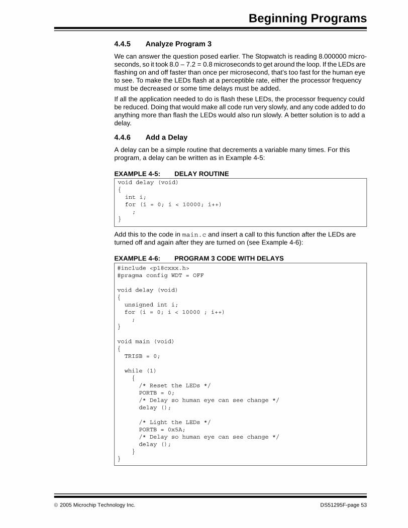
4.4.6 Add a Delay
A delay can be a simple routine that decrements a variable many times. For this program, a delay can be written as in Example 4-5:
EXAMPLE 4-5: DELAY ROUTINE
Add this to the code in main.c and insert a call to this function after the LEDs are turned off and again after they are turned on (see Example 4-6):
EXAMPLE 4-6: PROGRAM 3 CODE WITH DELAYS
void delay (void){ int i; for (i = 0; i < 10000; i++) ;}
#include <p18cxxx.h>#pragma config WDT = OFF
void delay (void){ unsigned int i; for (i = 0; i < 10000 ; i++) ;}
void main (void){ TRISB = 0;
while (1) { /* Reset the LEDs */ PORTB = 0; /* Delay so human eye can see change */ delay ();
/* Light the LEDs */ PORTB = 0x5A; /* Delay so human eye can see change */ delay (); }}
© 2005 Microchip Technology Inc. DS51295F-page 53

MPLAB® C18 C Compiler Getting Started
4.4.7 Build Program 3
Once again, select Project>Build All to rebuild everything after these changes are made to the source code, and add breakpoints on lines 18 and 23 where PORTB is written. Use the Stopwatch to measure the code.
The previously set breakpoints may also show up at different places in the code. Use the right mouse menu to Remove Breakpoint, leaving just the two desired breakpoints at lines 18 and 23.
Measure the time between breakpoints again. After stopping at the first breakpoint, press the Zero button on the Stopwatch to start measuring from this breakpoint.
With the variable i counting down from 10000, the measured time is about 36 millisec-onds. Remember that i is defined as an int, which has a range of -32768 to 32767 (MPLAB® C18 C Compiler User’s Guide). The largest value (32767) will make the delay about 3 times longer. If i is declared as unsigned int, its range can be extended to 65535 as shown in Figure 4-19. When set to this value, the measured delay is about 301 milliseconds, meaning that with both delays, it takes about 602 milli-seconds to go around the loop. This is just over a half second, so the lights will be flashing about twice a second. Refer to Figure 4-19.
FIGURE 4-19: FINAL CODE WITH 0.6 SECOND LED FLASH
4.4.8 Summary of Program 3
This completes the third program. In this example these topics were covered:
• Using processor-specific include files• Setting simulator processor frequency• Setting breakpoints• Using the MPLAB Stopwatch to measure time
DS51295F-page 54 © 2005 Microchip Technology Inc.

Beginning Programs
4.5 USING THE DEMO BOARD
This section demonstrates the previous program using hardware rather than simula-tion. If appropriate hardware is not available, skip this section. These hardware items are required in this section:
• MPLAB ICD 2 In-Circuit Debugger• PICDEM 2 Plus Demo Board with jumper J6 installed
4.5.1 Select MPLAB ICD 2
Install the MPLAB ICD 2 as instructed in the MPLAB IDE installation wizard. Connect the PICDEM 2 Plus board to a power supply and connect the ICD cable from MPLAB ICD 2 to the demo board.
Select MPLAB ICD 2 as the hardware debugger using Debugger>Select Tool>MPLAB ICD 2. Select Debugger>Connect to ensure that MPLAB ICD 2 has established communications with MPLAB IDE.
If everything is installed and connected properly, the Output window should look like Figure 4-20:
FIGURE 4-20: OUTPUT WINDOW FOR MPLAB® ICD 2
4.5.2 Program Code for Testing with MPLAB ICD 2
When debuggers are changed, the project must be rebuilt. Click the Build All icon.
Select Debugger>Program to download the program into the PICDEM 2 Plus demo board.
Note: If this operation failed because the MPLAB ICD 2 was not found or the USB port could not be opened, check the MPLAB IDE Document Viewer (in the Utilities folder in the MPLAB installed directory). It contains information on installing the USB drivers for MPLAB ICD 2.
Note: When using MPLAB ICD 2, special linker scripts are provided so that appli-cation code will not use the small areas in memory required for MPLAB ICD 2 debugging. The names of these linker scripts end in an “i” character. For the current project, use the linker script named 18f452i.lkr. Always use the “i” named linker scripts when debugging with MPLAB ICD 2.
© 2005 Microchip Technology Inc. DS51295F-page 55
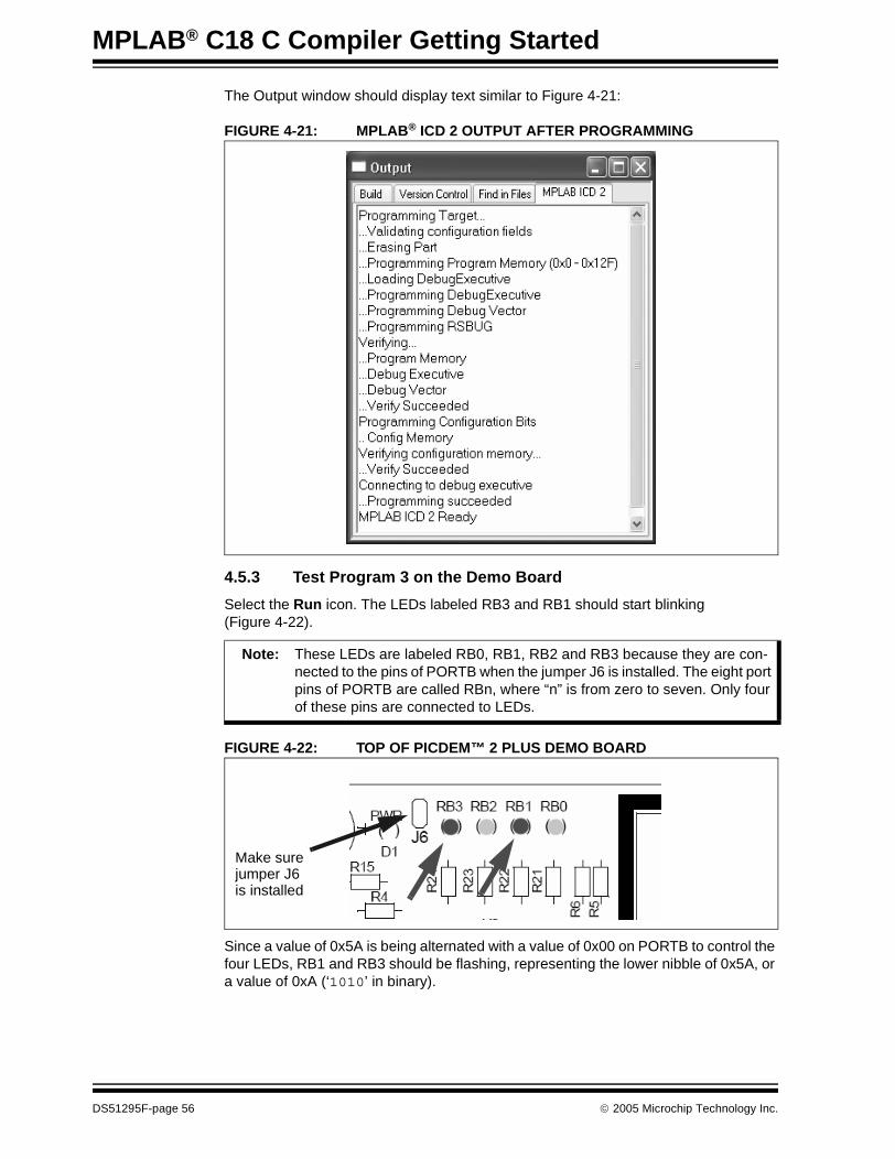
MPLAB® C18 C Compiler Getting Started
The Output window should display text similar to Figure 4-21:
FIGURE 4-21: MPLAB® ICD 2 OUTPUT AFTER PROGRAMMING
4.5.3 Test Program 3 on the Demo Board
Select the Run icon. The LEDs labeled RB3 and RB1 should start blinking (Figure 4-22).
FIGURE 4-22: TOP OF PICDEM™ 2 PLUS DEMO BOARD
Since a value of 0x5A is being alternated with a value of 0x00 on PORTB to control the four LEDs, RB1 and RB3 should be flashing, representing the lower nibble of 0x5A, or a value of 0xA (‘1010’ in binary).
Note: These LEDs are labeled RB0, RB1, RB2 and RB3 because they are con-nected to the pins of PORTB when the jumper J6 is installed. The eight port pins of PORTB are called RBn, where “n” is from zero to seven. Only four of these pins are connected to LEDs.
Make surejumper J6is installed
DS51295F-page 56 © 2005 Microchip Technology Inc.

Beginning Programs
They are probably blinking slower than was predicted when the Stopwatch in the simulator was used in Program 3. This is because the PICDEM 2 Plus demo board is shipped with a 4 MHz oscillator, and the simulator timings were done with a clock frequency of 20 MHz. The value of the delay loop can be reduced back to 10000 to blink faster.
4.5.4 Programming the Processor on the Demo Board
When MPLAB ICD 2 is operating as a debugger, the program can be single stepped, variables can be put into watch windows, and the program can be run and halted as in the simulator.
When the program is fully functional, it can be programmed into the target device so it can run without being connected to MPLAB ICD 2 and the PC.
4.5.5 Deselect MPLAB ICD 2 as Debugger
To disable MPLAB ICD 2 as a debugger, select Debugger>Select Tool>None.
4.5.6 Set MPLAB ICD 2 as Programmer
Select Programmer>Select Programmer>MPLAB ICD 2 to enable MPLAB ICD 2 as a programmer.
Note: The Stopwatch is a debugging function of the simulator. MPLAB ICD 2 does not have an equivalent function.
Note: When using MPLAB ICD 2 as a debugger, special code is downloaded into the target device and the device is put into the In-Circuit Debug mode. For the final application, these MPLAB ICD 2 functions need to be turned off.
© 2005 Microchip Technology Inc. DS51295F-page 57
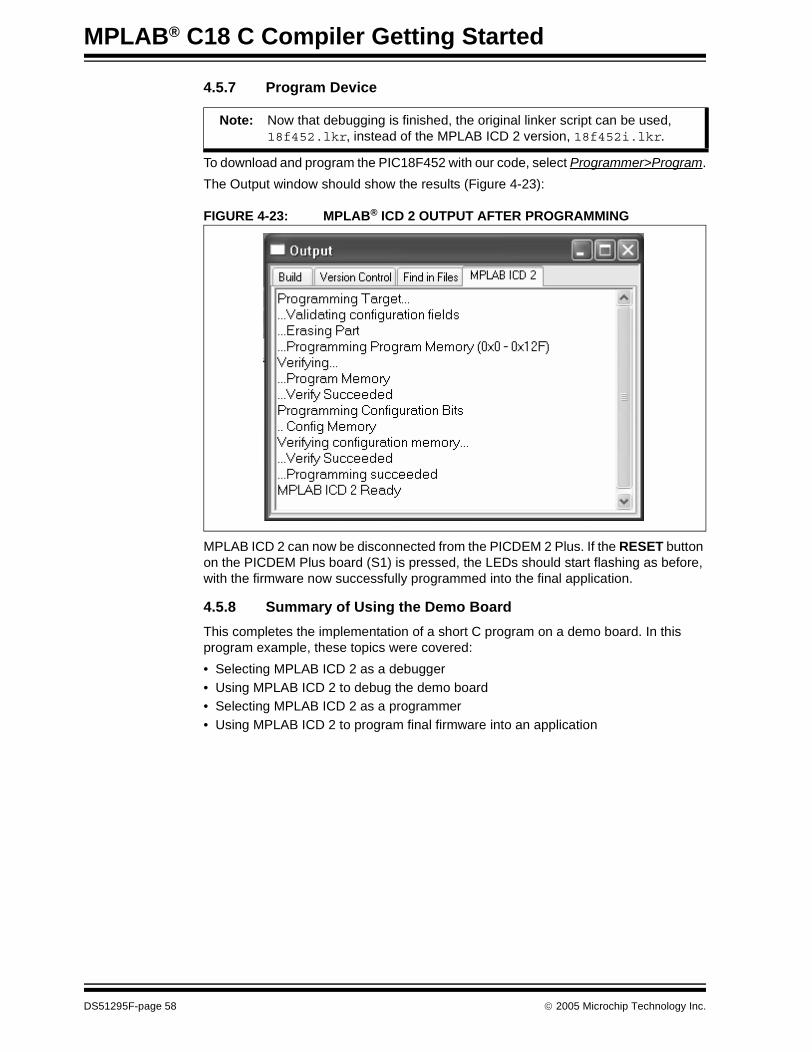
MPLAB® C18 C Compiler Getting Started
4.5.7 Program Device
To download and program the PIC18F452 with our code, select Programmer>Program.
The Output window should show the results (Figure 4-23):
FIGURE 4-23: MPLAB® ICD 2 OUTPUT AFTER PROGRAMMING
MPLAB ICD 2 can now be disconnected from the PICDEM 2 Plus. If the RESET button on the PICDEM Plus board (S1) is pressed, the LEDs should start flashing as before, with the firmware now successfully programmed into the final application.
4.5.8 Summary of Using the Demo Board
This completes the implementation of a short C program on a demo board. In this program example, these topics were covered:
• Selecting MPLAB ICD 2 as a debugger• Using MPLAB ICD 2 to debug the demo board• Selecting MPLAB ICD 2 as a programmer• Using MPLAB ICD 2 to program final firmware into an application
Note: Now that debugging is finished, the original linker script can be used, 18f452.lkr, instead of the MPLAB ICD 2 version, 18f452i.lkr.
DS51295F-page 58 © 2005 Microchip Technology Inc.

MPLAB® C18 C COMPILER
GETTING STARTEDChapter 5. Features
5.1 OVERVIEW
This chapter presents a description of many of the features of MPLAB C18 as controlled from the MPLAB user interface. Demonstration projects will show some of the features of MPLAB C18 and the MPLAB debugger. All of these projects can be built with source code copied from these demonstrations and pasted into the MPLAB editor.
This chapter covers these topics:
• MPLAB Project Build Options- General Options- Memory Model Options- Optimization Options
• Demonstration: Code Optimization• Demonstration: Displaying Data in Watch Windows
- Basic Data Types- Arrays- Structures- Pointers- Map Files
5.2 MPLAB PROJECT BUILD OPTIONS
The MPLAB Project Manager has settings that control the MPLAB C18 compiler, the MPASM assembler, and MPLINK linker. Project options can be set for the entire project and can be separately adjusted for each source file.
The project build options has these tabs to control the language tool options for the project:
• General – Set paths for the project.• MPASM/C17/C18 Suite – Sets normal or library as build target.• MPASM Assembler – Control MPASM switches, such as case sensitivity,
enabling the PIC18XXXX Extended mode, hex file format and warning and error messages.
• MPLINK Linker – Determine hex file format, map file and debugging output file generation.
• MPLAB C18 – Set general, memory model and optimization options.
Note: The build settings can be customized separately for each file. Select Project>Build Options...><file name> to display the options for each individual file in the project.
© 2005 Microchip Technology Inc. DS51295F-page 59
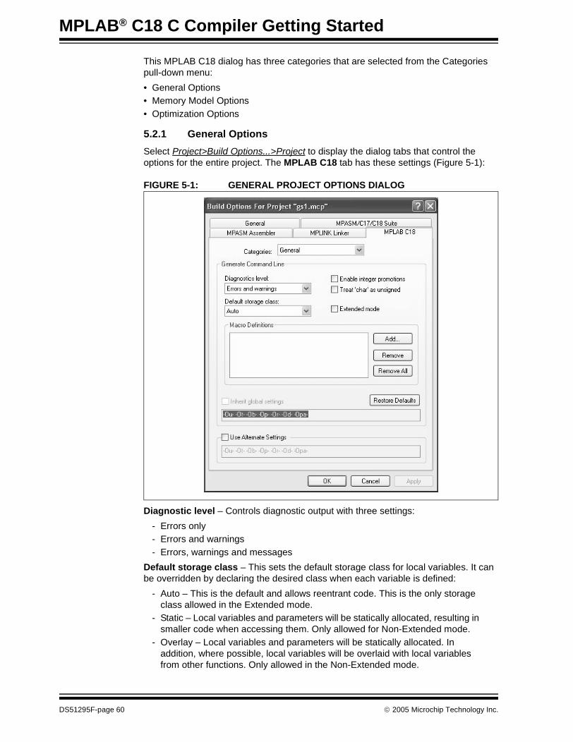
MPLAB® C18 C Compiler Getting Started
This MPLAB C18 dialog has three categories that are selected from the Categories pull-down menu:
• General Options• Memory Model Options• Optimization Options
5.2.1 General Options
Select Project>Build Options...>Project to display the dialog tabs that control the options for the entire project. The MPLAB C18 tab has these settings (Figure 5-1):
FIGURE 5-1: GENERAL PROJECT OPTIONS DIALOG
Diagnostic level – Controls diagnostic output with three settings:
- Errors only- Errors and warnings- Errors, warnings and messages
Default storage class – This sets the default storage class for local variables. It can be overridden by declaring the desired class when each variable is defined:
- Auto – This is the default and allows reentrant code. This is the only storage class allowed in the Extended mode.
- Static – Local variables and parameters will be statically allocated, resulting in smaller code when accessing them. Only allowed for Non-Extended mode.
- Overlay – Local variables and parameters will be statically allocated. In addition, where possible, local variables will be overlaid with local variables from other functions. Only allowed in the Non-Extended mode.
DS51295F-page 60 © 2005 Microchip Technology Inc.

Features
Enable integer promotions – The ANSI C standard requires that arithmetic operations be performed at the int precision level (16-bit) or higher. When this option is not enabled, the application may benefit from code size savings. This box should be checked if ANSI C compatibility is desired.
Treat ‘char’ as unsigned – Since the PIC18XXXX has a data path of 8 bits, often values from 0 to 255 (0xFF) are used in computation. Normally, char defines a variable that has a range from -128 to 127. Treating a plain char as unsigned allows only positive values from 0 to 255, and in some applications may be more suitable for computations when dealing with small variables in this 8-bit microcontroller.
Extended mode – Allows compilation for the PIC18XXXX Extended mode. When using PIC18XXXX devices that support the Extended mode, the appropriate linker script must be used. Extended mode linker scripts have names ending in ‘_e’, for example, 18f2520_e.lkr.
Macro Definitions – Macros can be added to the Macro Definitions section using the Add button. This is equivalent to using the -D command-line option as described in the “Introduction” of the MPLAB C18 C Compiler User’s Guide.
Inherit global settings – When this box is checked, the file will inherit all the settings from the project.
Use Alternate Settings – When this box is checked, settings are applied to this file only. This allows other compiler command-line options that are not supported by this MPLAB dialog. See the MPLAB C18 C Compiler User’s Guide for more information on compiler switches.
© 2005 Microchip Technology Inc. DS51295F-page 61

MPLAB® C18 C Compiler Getting Started
5.2.2 Memory Model Options
This dialog provides individual control over the compiler memory model (Figure 5-2).
FIGURE 5-2: MEMORY MODEL OPTIONS DIALOG
Code Model – This sets program memory pointer default size as 16 or 24 bits. This can be overridden for each variable by declaring the pointer as near (16 bits) or far (24 bits). Using 16-bit pointers (small code model) results in more efficient code, but if pointers are used for program memory data (romdata) in devices with more than 64 Kbytes of program data, 24-bit pointers (large code model) should be employed.
Data Model – Default data sections (idata and udata) are located in Access RAM (small data model) or banked RAM (large data model). The location of a particular variable can be overridden on each variable by declaring it near or far and creating a section in the correct memory region.
Stack Model – This sets the ability of the data stack to extend beyond one bank. The size and location of the stack is set in the linker script. If the linker script defines the stack as extending beyond a single bank, then the stack should be set to the “Multi-bank model.” If a larger stack is used, a slight performance penalty will result since the data Stack Pointer needs to be handled by 16-bit rather than 8-bit arithmetic.
Note: The small data model can only be used in the Non-Extended mode.
DS51295F-page 62 © 2005 Microchip Technology Inc.

Features
5.2.3 Optimization Options
This dialog provides individual control over each of the compiler optimizations (Figure 5-3). For details on each optimization, see the MPLAB® C18 C Compiler User’s Guide chapter on “Optimizations.”
Generally, while debugging code, it is recommended to use the Debug setting.
FIGURE 5-3: OPTIMIZATION OPTIONS DIALOG
Optimizations can be controlled with the buttons under Generate Command Line. See the MPLAB C18 C Compiler User’s Guide chapter on “Optimizations” for details on individual optimizations. There are four settings:
Disable – This disables all optimizations.
Debug – This enables most optimizations but disables those that adversely affect debugging, specifically, duplicate string merging, code straightening and WREG tracking.
Enable all – Enable all debugging.
Custom – Enable selected optimizations.
Procedural-abstraction passes – The procedural abstraction optimization can be performed more than once. By default, four passes are run. More passes can be used to try to further reduce code size, but this can produce too many functions being abstracted, resulting in an overflow of the return stack at run time. Fewer than four passes can be set to minimize the impact to the return stack.
© 2005 Microchip Technology Inc. DS51295F-page 63

MPLAB® C18 C Compiler Getting Started
5.3 DEMONSTRATION: CODE OPTIMIZATION
This section will present an example of how code optimizations can affect project debugging. Code will be created and built with no optimizations. Single stepping through the code will demonstrate expected behavior of the code.
Then, the code will be optimized and it will be shown that single stepping yields correct operation, but the code flow will be altered (optimized), making debugging more difficult.
5.3.1 Create Optimization Project
To duplicate this demonstration, create a new project in MPLAB IDE with Project>New... (see Figure 5-4). Name it “Optimizations” and create a new project directory named “More Projects”.
FIGURE 5-4: CREATE OPTIMIZATION PROJECT
DS51295F-page 64 © 2005 Microchip Technology Inc.

Features
Use File>New to create a new file and copy or type in the following code (Example 5-1). Use File>Save to save it in the More Projects directory with the file name, optimizations.c.
EXAMPLE 5-1: OPTIMIZATIONS CODE#include <stdio.h>
void main (void){ int j = 0; int i;
for (i = 0; i < 10; i++) { printf ("%d:\t", i);
if (i % 2) { printf ("ODD"); j += i; } else { printf ("EVEN"); j += i; }
printf ("\tj = %d\n", j); }
while (1) ;}
© 2005 Microchip Technology Inc. DS51295F-page 65
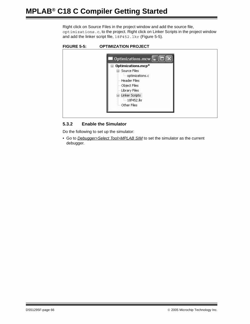
MPLAB® C18 C Compiler Getting Started
Right click on Source Files in the project window and add the source file, optimizations.c, to the project. Right click on Linker Scripts in the project window and add the linker script file, 18F452.lkr (Figure 5-5).
FIGURE 5-5: OPTIMIZATION PROJECT
5.3.2 Enable the Simulator
Do the following to set up the simulator:
• Go to Debugger>Select Tool>MPLAB SIM to set the simulator as the current debugger.
DS51295F-page 66 © 2005 Microchip Technology Inc.

Features
5.3.3 Turn Off Optimizations
Set the build options for debugging by doing these steps:
• Select Project>Build Options>Project to bring up the build dialogs. • Select the MPLAB C18 tab and select Categories: Optimizations to display the
dialog shown below.• Select Debug as shown in Figure 5-6 to suppress optimizations that adversely
affect debugging.
FIGURE 5-6: BUILD OPTIONS: OPTIMIZATIONS FOR DEBUGGING
© 2005 Microchip Technology Inc. DS51295F-page 67

MPLAB® C18 C Compiler Getting Started
5.3.4 Check Settings
• Double check the General tab to see that the Include path and the Library path are correctly set up as shown in Section 3.7 “Verify Installation and Build Options”.
• Also, check Debugger>Settings and click on the Uart1 IO settings. Make sure that the Enable Uart1 IO box is checked and that the Output is set to Window.
5.3.5 Build and Test the Project
Use Project>Build All or the Build All icon on the tool bar to build the project.
Click the Run icon and inspect the Output window to see that the code executed properly. The Output window should show:
0: EVEN j = 01: ODD j = 12: EVEN j = 33: ODD j = 64: EVEN j = 105: ODD j = 156: EVEN j = 217: ODD j = 288: EVEN j = 369: ODD j = 45
5.3.6 Single Step Through the Code
Click the Halt icon and then the Reset icon to ensure that the code is ready to start from the beginning.
Set a breakpoint on the “for” loop and click the Run icon to halt at the beginning of the main program loop as shown in Figure 5-7:
FIGURE 5-7: OPTIMIZATION EXAMPLE – OPTIMIZATION OFF STEP 1
Click the Step Over button to step through the code. Click Step Over again to get to the “if” statement (Figure 5-8).
FIGURE 5-8: OPTIMIZATION EXAMPLE – OPTIMIZATION OFF STEP 2
DS51295F-page 68 © 2005 Microchip Technology Inc.

Features
Click Step Over again to go to the “else” part of the statement. The modulus (%) operation is false the first time through this loop, so as seen from the Output window, the first line printed in the Output window is “Even” (Figure 5-9).
FIGURE 5-9: OPTIMIZATION EXAMPLE – OPTIMIZATION OFF STEP 3
Continue clicking Step Over to get back to the “if” statement (Figure 5-10, Figure 5-12, Figure 5-13 and Figure 5-14).
FIGURE 5-10: OPTIMIZATION EXAMPLE – OPTIMIZATION OFF STEP 4
© 2005 Microchip Technology Inc. DS51295F-page 69

MPLAB® C18 C Compiler Getting Started
FIGURE 5-11: OPTIMIZATION EXAMPLE – OPTIMIZATION OFF STEP 5
FIGURE 5-12: OPTIMIZATION EXAMPLE – OPTIMIZATION OFF STEP 6
FIGURE 5-13: OPTIMIZATION EXAMPLE – OPTIMIZATION OFF STEP 7
FIGURE 5-14: OPTIMIZATION EXAMPLE – OPTIMIZATION OFF STEP 8
DS51295F-page 70 © 2005 Microchip Technology Inc.

Features
Continuing the Step Over of code to get to line 15, the “j += i” statement in the “if” portion of the function (Figure 5-15 and Figure 5-16):
FIGURE 5-15: OPTIMIZATION EXAMPLE – OPTIMIZATION OFF STEP 9
FIGURE 5-16: OPTIMIZATION EXAMPLE – OPTIMIZATION OFF STEP 10
This section was presented to show the code running without optimizations. Single stepping through the code proceeded logically, as expected. The next section will show how the code behaves after it has been optimized.
© 2005 Microchip Technology Inc. DS51295F-page 71
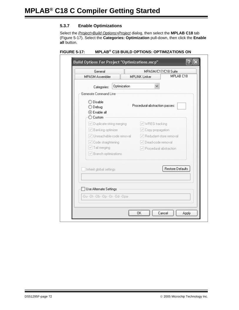
MPLAB® C18 C Compiler Getting Started
5.3.7 Enable Optimizations
Select the Project>Build Options>Project dialog, then select the MPLAB C18 tab (Figure 5-17). Select the Categories: Optimization pull-down, then click the Enable all button.
FIGURE 5-17: MPLAB® C18 BUILD OPTIONS: OPTIMIZATIONS ON
DS51295F-page 72 © 2005 Microchip Technology Inc.
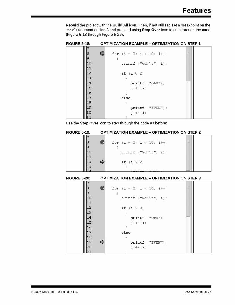
Features
Rebuild the project with the Build All icon. Then, if not still set, set a breakpoint on the “for” statement on line 8 and proceed using Step Over icon to step through the code (Figure 5-18 through Figure 5-26).
FIGURE 5-18: OPTIMIZATION EXAMPLE – OPTIMIZATION ON STEP 1
Use the Step Over icon to step through the code as before:
FIGURE 5-19: OPTIMIZATION EXAMPLE – OPTIMIZATION ON STEP 2
FIGURE 5-20: OPTIMIZATION EXAMPLE – OPTIMIZATION ON STEP 3
© 2005 Microchip Technology Inc. DS51295F-page 73

MPLAB® C18 C Compiler Getting Started
FIGURE 5-21: OPTIMIZATION EXAMPLE – OPTIMIZATION ON STEP 4
FIGURE 5-22: OPTIMIZATION EXAMPLE – OPTIMIZATION ON STEP 5
FIGURE 5-23: OPTIMIZATION EXAMPLE – OPTIMIZATION ON STEP 6
FIGURE 5-24: OPTIMIZATION EXAMPLE – OPTIMIZATION ON STEP 7
DS51295F-page 74 © 2005 Microchip Technology Inc.

Features
FIGURE 5-25: OPTIMIZATION EXAMPLE – OPTIMIZATION ON STEP 8
FIGURE 5-26: OPTIMIZATION EXAMPLE – OPTIMIZATION ON STEP 9
The next Step Over yields something surprising. In the figure above, the program counter arrow was in the “if” portion of the function. Now the program counter jumps to the “else” part of the function (Figure 5-27):
FIGURE 5-27: OPTIMIZATION EXAMPLE – OPTIMIZATION ON STEP 10
© 2005 Microchip Technology Inc. DS51295F-page 75

MPLAB® C18 C Compiler Getting Started
One more Step Over shows the “j += i” statement in the “else” portion of the code ready to be executed (Figure 5-28):
FIGURE 5-28: OPTIMIZATION EXAMPLE – OPTIMIZATION ON STEP 11
This section demonstrates that the code has been optimized using “tail merging” techniques. The “j += i” statement that is in both the “if” and the “else” section of the code has been optimized from two separate sets of code into one.
When single stepping, the code jumps to a portion of the “else” clause while actually executing the “if” portion of the code. The first “j += i” statement on line 15 in the figure above has been eliminated. This optimization can cause puzzling effects when debugging. The code is executing as designed, but the compiler has reorganized it to generate fewer instructions.
5.4 DEMONSTRATION: DISPLAYING DATA IN WATCH WINDOWS
5.4.1 Basic Data Types
Variables in MPLAB C18 can be added to Watch windows. MPLAB IDE can correctly show the values with the formatting appropriate for each data type.
This demonstration can be done using a new project. Select Project>New Project, set the project name to “Data Types” and set the project directory to the same directory used in the previous demonstration (Figure 5-29):
FIGURE 5-29: DEMONSTRATION: DATA TYPES
DS51295F-page 76 © 2005 Microchip Technology Inc.
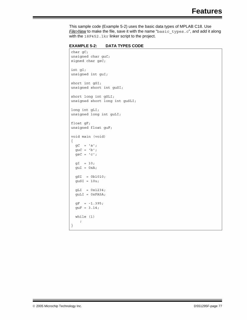
Features
This sample code (Example 5-2) uses the basic data types of MPLAB C18. Use File>New to make the file, save it with the name “basic_types.c”, and add it along with the 18F452.lkr linker script to the project.
EXAMPLE 5-2: DATA TYPES CODEchar gC;unsigned char guC;signed char gsC;
int gI;unsigned int guI;
short int gSI;unsigned short int guSI;
short long int gSLI;unsigned short long int guSLI;
long int gLI;unsigned long int guLI;
float gF;unsigned float guF;
void main (void){ gC = 'a'; guC = 'b'; gsC = 'c';
gI = 10; guI = 0xA;
gSI = 0b1010; guSI = 10u;
gLI = 0x1234; guLI = 0xFA5A;
gF = -1.395; guF = 3.14;
while (1) ;}
© 2005 Microchip Technology Inc. DS51295F-page 77
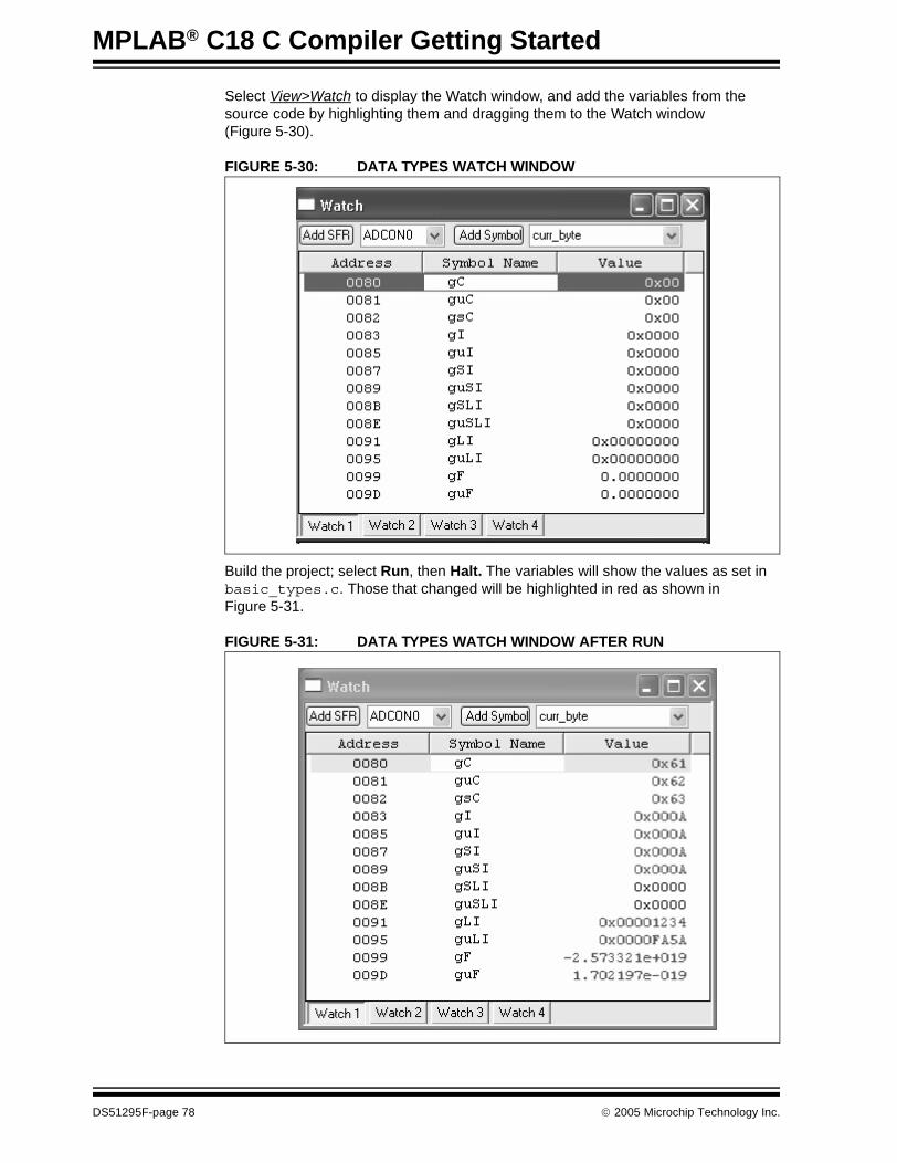
MPLAB® C18 C Compiler Getting Started
Select View>Watch to display the Watch window, and add the variables from the source code by highlighting them and dragging them to the Watch window (Figure 5-30).
FIGURE 5-30: DATA TYPES WATCH WINDOW
Build the project; select Run, then Halt. The variables will show the values as set in basic_types.c. Those that changed will be highlighted in red as shown in Figure 5-31.
FIGURE 5-31: DATA TYPES WATCH WINDOW AFTER RUN
DS51295F-page 78 © 2005 Microchip Technology Inc.

Features
5.4.2 Arrays
Arrays are displayed in MPLAB C18 Watch windows as collapsible items, allowing them to be expanded to be examined, then collapsed to make more room when watching other variables. To demonstrate, use the following code (Example 5-3) to make a new source file named arrays.c and a new project, also named “Arrays”.
EXAMPLE 5-3: ARRAYS CODE
Put the file named array.c into a project with the 18F452.lkr linker script (Figure 5-32).
FIGURE 5-32: ARRAYS PROJECT
Select View>Watch to open up a Watch window and drag the arrays named “x” and “i” into the Watch window (Figure 5-33).
FIGURE 5-33: WATCH ARRAYS
char x[] = "abc";int i[] = { 1, 2, 3, 4, 5};
void main (void){ while (1); ;
}
© 2005 Microchip Technology Inc. DS51295F-page 79

MPLAB® C18 C Compiler Getting Started
Make sure the simulator is selected as the debugger, Build the project and Run it. After clicking Halt, the arrays can be examined. In Figure 5-34, the “+” sign next to each array was expanded. Note the values in the arrays after the program was executed.
FIGURE 5-34: ARRAYS EXPANDED
5.4.3 Structures
Like arrays, structures in MPLAB C18 show up on Watch windows as expandable/ collapsible elements.
Example 5-4 demonstration code will be used to show how structures appear in MPLAB C18 Watch windows.
EXAMPLE 5-4: STRUCTURES CODE
struct { int x; char y[4];} s1 = { 0x5A, “abc” };
struct { int x[5]; int y;} s2 = { { 10, 22, 30, 40, 50 }, 0xA5 };
void main (void){ while (1) ;
}
DS51295F-page 80 © 2005 Microchip Technology Inc.

Features
Make a project (Figure 5-35) with this source file, add the 18F452.lkr linker script, then set up the simulator as the debugger and build it.
FIGURE 5-35: STRUCTURES: PROJECT
Before running, the Watch window should look like Figure 5-36 when every element is fully expanded:
FIGURE 5-36: STRUCTURES: WATCH WINDOW
© 2005 Microchip Technology Inc. DS51295F-page 81
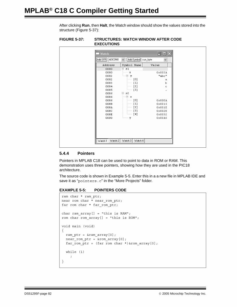
MPLAB® C18 C Compiler Getting Started
After clicking Run, then Halt, the Watch window should show the values stored into the structure (Figure 5-37):
FIGURE 5-37: STRUCTURES: WATCH WINDOW AFTER CODE EXECUTIONS
5.4.4 Pointers
Pointers in MPLAB C18 can be used to point to data in ROM or RAM. This demonstration uses three pointers, showing how they are used in the PIC18 architecture.
The source code is shown in Example 5-5. Enter this in a a new file in MPLAB IDE and save it as “pointers.c” in the “More Projects” folder.
EXAMPLE 5-5: POINTERS CODE
ram char * ram_ptr;near rom char * near_rom_ptr;far rom char * far_rom_ptr;
char ram_array[] = "this is RAM";rom char rom_array[] = "this is ROM";
void main (void){ ram_ptr = &ram_array[0]; near_rom_ptr = &rom_array[0]; far_rom_ptr = (far rom char *)&rom_array[0];
while (1) ;
}
DS51295F-page 82 © 2005 Microchip Technology Inc.
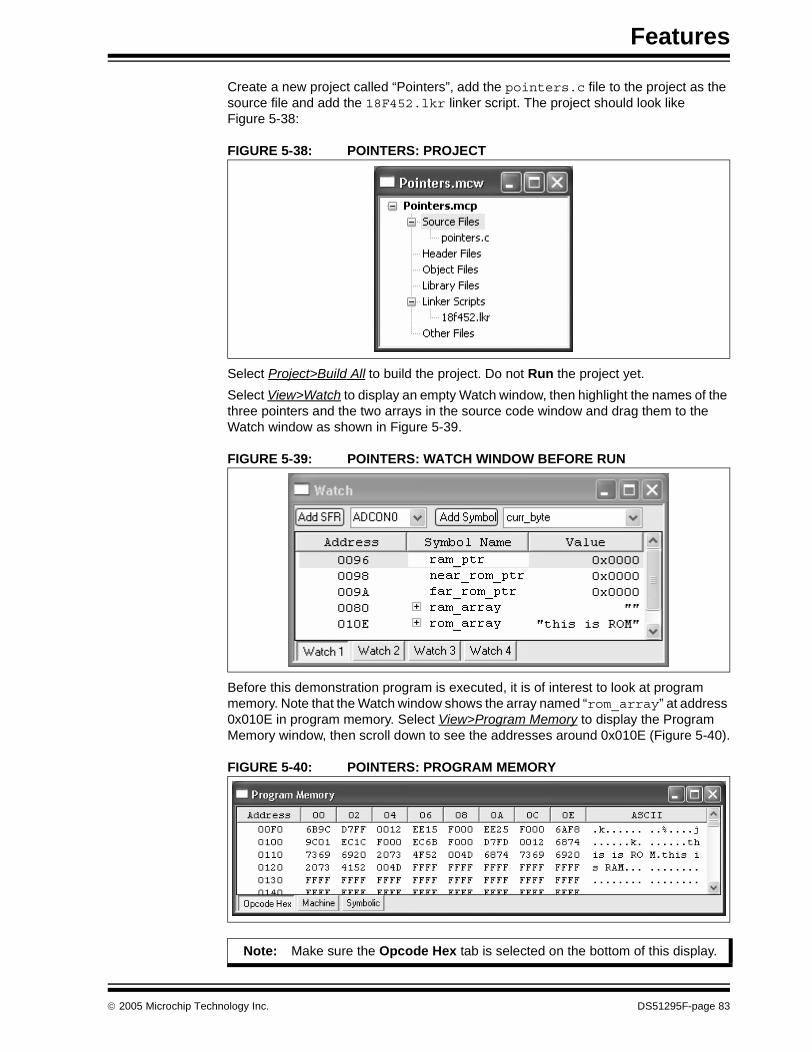
Features
Create a new project called “Pointers”, add the pointers.c file to the project as the source file and add the 18F452.lkr linker script. The project should look like Figure 5-38:
FIGURE 5-38: POINTERS: PROJECT
Select Project>Build All to build the project. Do not Run the project yet.
Select View>Watch to display an empty Watch window, then highlight the names of the three pointers and the two arrays in the source code window and drag them to the Watch window as shown in Figure 5-39.
FIGURE 5-39: POINTERS: WATCH WINDOW BEFORE RUN
Before this demonstration program is executed, it is of interest to look at program memory. Note that the Watch window shows the array named “rom_array” at address 0x010E in program memory. Select View>Program Memory to display the Program Memory window, then scroll down to see the addresses around 0x010E (Figure 5-40).
FIGURE 5-40: POINTERS: PROGRAM MEMORY
Note: Make sure the Opcode Hex tab is selected on the bottom of this display.
© 2005 Microchip Technology Inc. DS51295F-page 83

MPLAB® C18 C Compiler Getting Started
The text that was set in the ROM array named “rom_array” at 0x010E clearly has the text “this is ROM” stored in program memory.
Click the Run icon to execute the program, then click the Halt icon. The Watch window (Figure 5-41) should now show values for the three pointers, and the file register (RAM) area contains the “this is RAM” string.
FIGURE 5-41: POINTERS: WATCH WINDOW AFTER RUN
Note: The text for the RAM array, “this is RAM”, is also seen immediately after Figure 5-40. Why is this? This is an example of initialized data. The RAM array is defined in the source code, but when the PIC18 device is initially powered up, the contents of RAM are not set – they will have random values. In order to initialize this RAM when the program is run, the MPLAB C18 initialization code executes (c018i.o included as a precompiled library from the linker script), moving this text from program memory into RAM.
DS51295F-page 84 © 2005 Microchip Technology Inc.

Features
The arrays can be expanded to show the address of the individual elements (Figure 5-42):
FIGURE 5-42: POINTERS: WATCH WINDOW ARRAY EXPANDED
Select View>File Registers and scroll down to address 0x0080 to see the contents of the RAM array (see Figure 5-43).
FIGURE 5-43: POINTERS: FILE REGISTERS AFTER RUN
© 2005 Microchip Technology Inc. DS51295F-page 85
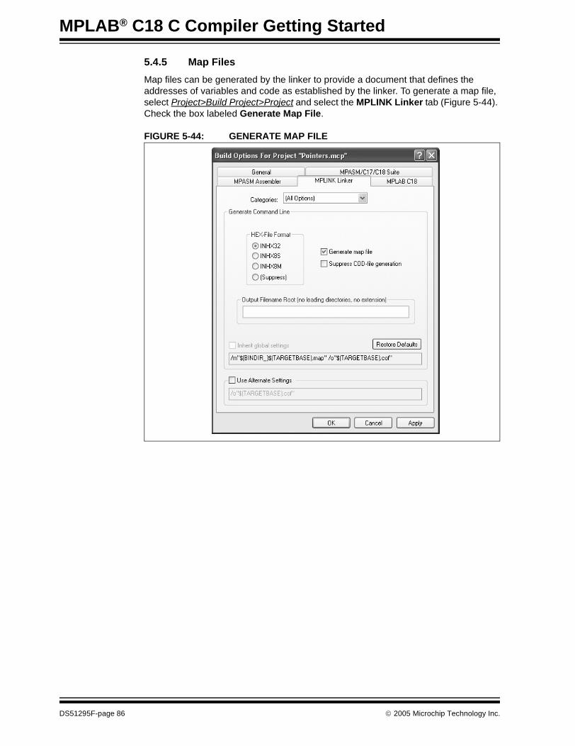
MPLAB® C18 C Compiler Getting Started
5.4.5 Map Files
Map files can be generated by the linker to provide a document that defines the addresses of variables and code as established by the linker. To generate a map file, select Project>Build Project>Project and select the MPLINK Linker tab (Figure 5-44). Check the box labeled Generate Map File.
FIGURE 5-44: GENERATE MAP FILE
DS51295F-page 86 © 2005 Microchip Technology Inc.
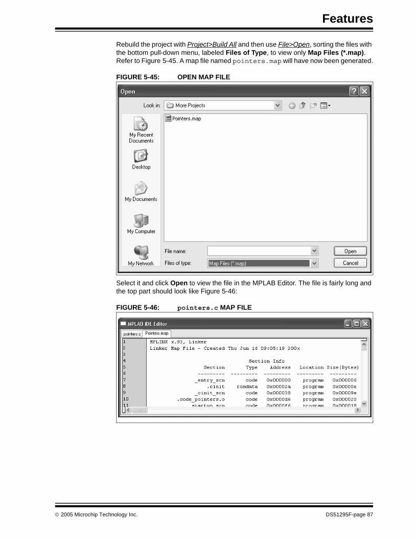
Features
Rebuild the project with Project>Build All and then use File>Open, sorting the files with the bottom pull-down menu, labeled Files of Type, to view only Map Files (*.map). Refer to Figure 5-45. A map file named pointers.map will have now been generated.
FIGURE 5-45: OPEN MAP FILE
Select it and click Open to view the file in the MPLAB Editor. The file is fairly long and the top part should look like Figure 5-46:
FIGURE 5-46: pointers.c MAP FILE
© 2005 Microchip Technology Inc. DS51295F-page 87
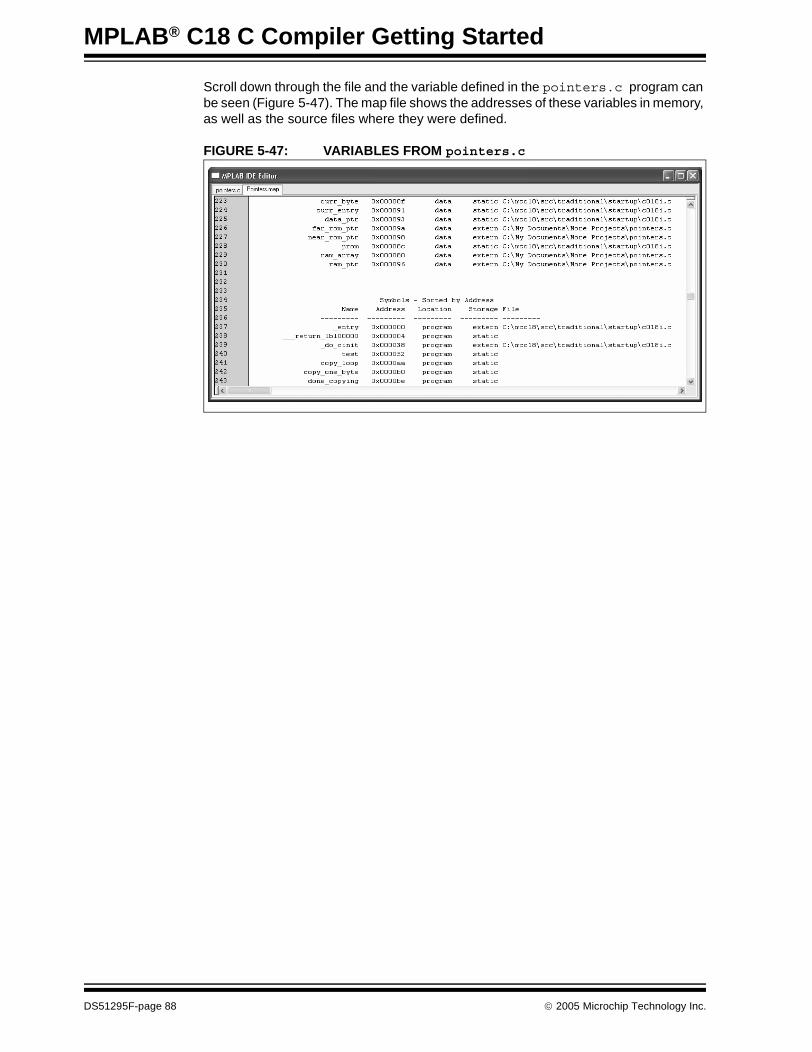
MPLAB® C18 C Compiler Getting Started
Scroll down through the file and the variable defined in the pointers.c program can be seen (Figure 5-47). The map file shows the addresses of these variables in memory, as well as the source files where they were defined.
FIGURE 5-47: VARIABLES FROM pointers.c
DS51295F-page 88 © 2005 Microchip Technology Inc.
MPLAB® C18 C COMPILER
GETTING STARTEDChapter 6. Architecture
6.1 INTRODUCTION
Every implementation of a C compiler must support specific features of the target processor. In the case of MPLAB C18, the unique characteristics of the PIC18XXXX require that consideration be given to the memory structure, interrupts, Special Function Registers and other details of the microcontroller core that are outside the scope of the standard C language. This chapter provides an overview of some of these PIC18XXXX specific issues that are covered in complete detail in the data sheets:
• PIC18XXXX Architecture• MPLAB C18 Start-up Code• #pragma Directive• Sections• SFRS, Timers SW/HW• Interrupts• Math and I/O Libraries
© 2005 Microchip Technology Inc. DS51295F-page 89

MPLAB® C18 C Compiler Getting Started
6.2 PIC18XXXX ARCHITECTURE
The PIC18XXXX MCUs are “Harvard architecture” microprocessors, meaning that program memory and data memory are in separate spaces. The return stack has its own dedicated memory and there is another nonvolatile memory space if the particular device has on-board data EEPROM memory.
6.2.1 Program Memory
The program memory space is addressed by a 21-bit Program Counter, allowing a 2 Mb program memory space (Figure 6-1). Typically, PIC18XXXX MCUs have on-chip program memory in the range of 16K to 128K. Some devices allow external memory expansion.
At Reset, the Program Counter is set to zero and the first instruction is fetched. Interrupt vectors are at locations 0x000008 and 0x000018, so a GOTO instruction is usually placed at address zero to jump over the interrupt vectors.
FIGURE 6-1: PIC18F452 PROGRAM MEMORY
Program memory contains 16-bit words. Most instructions are 16 bits, but some are double word 32-bit instructions. Instructions cannot be executed on odd numbered bytes.
PIC18F devices have Flash program memory and PIC18C devices have OTP (One-Time-Programmable) memory (or in some cases, UV erasable windowed devices). Usually, the OTP memory is written only when the firmware is programmed into the device. Flash memory can be erased and rewritten by the running program. Both OTP and Flash devices are programmed by a few interconnections to the device, allowing them to be programmed after they are soldered on to the target PC board.
PC<20:0>
Stack Level 1•
Stack Level 31
RESET Vector
Low Priority Interrupt Vector
••
CALL,RCALL,RETURNRETFIE,RETLW
21
0000h
0018h
8000h
7FFFh
On-ChipProgram Memory
High Priority Interrupt Vector 0008h
Use
r M
emor
y S
pace
Read ‘0’
1FFFFFh200000h
DS51295F-page 90 © 2005 Microchip Technology Inc.
Architecture
These are some important characteristics of the PIC18 architecture and MPLAB C18 capabilities with reference to program memory:
MPLAB C18 Implementation
Refer to the MPLAB C18 C Compiler User’s Guide for more information on these features.
• Instructions are typically stored in program memory with the section attribute code.
• Data can be stored in program memory with the section attribute romdata in conjunction with the rom keyword.
• MPLAB C18 can be configured to generate code for two memory models, small and large. When using the small memory model, pointers to program memory use 16 bits. The large model uses 24-bit pointers.
PIC18 Architecture
• The GOTO instruction and the CALL instruction are double word (32-bit) instructions and can jump anywhere in program memory.
• If the second word of a double word instruction is executed (by branching or jumping into the middle of the instruction with a GOTO instruction), it will always execute as a NOP.
• All instructions are aligned on even word boundaries.• In some PIC18XXXX devices, program memory or portions of program memory
can be code-protected. Code will execute properly but it cannot be read out or copied.
• Program memory can be read using table read instructions, and can be written through a special code sequence using the table write instruction.
© 2005 Microchip Technology Inc. DS51295F-page 91

MPLAB® C18 C Compiler Getting Started
6.2.2 Data Memory
Data memory is called “file register” memory in the PIC18XXXX family. It consists of up to 4096 bytes of 8-bit RAM. Upon power-up, the values in data memory are random. Data is organized in banks of 256 bytes. The PIC18 instructions read and write file registers using only 8 bits for the register address, requiring that a bank (the upper 4 bits of the register address) be selected with the Bank Select Register (BSR). Twelve-bit pointers allow indirect access to the full RAM space without banking. In addition, special areas in Bank 0 and in Bank 15 can be accessed directly without concern for banking and the contents of the BSR register. These special data areas are called Access RAM. The high Access RAM area is where most of the Special Function Registers are located (see Figure 6-2). This description applies to the Non-Extended mode only.
FIGURE 6-2: PIC18F452 DATA MEMORY
Uninitialized data memory variables, arrays and structures are usually stored in memory with the section attribute, udata.
Initialized data can be defined in MPLAB C18 so that variables will have correct values when the compiler initialization executes. This means that the values are stored in program memory, then moved to data memory on start-up. Depending upon how much initialized memory is required for the application, the use of initialized data (rather than simply setting the data values at run time) may adversely affect the efficient use of program memory.
Since file registers are 8 bits, when using variables, consideration should be made whether to define them as int or char. When a variable value is not expected to exceed 255, defining it as an unsigned char will result in smaller, faster code.
Bank 0
Bank 1
Bank 14
Bank 15
Data Memory Map
080h07Fh
F80hFFFh
00h
7Fh80h
FFh
Access BankBank 4
Bank 3
Bank 2
F7FhF00hEFFh
3FFh
300h2FFh
200h1FFh
100h0FFh
000hAccess RAM
FFh
00h
FFh
00h
FFh
00h
FFh
00h
FFh
00h
FFh
00h
GPR
GPR
GPR
GPR
SFR
Unused
Access RAM high
Access RAM lowBank 5
GPR
GPR
Bank 6to
4FFh
400h
5FFh
500h
600h
UnusedRead ‘00h’
(SFRs)
DS51295F-page 92 © 2005 Microchip Technology Inc.

Architecture
6.2.3 Special Function Registers
Special Function Registers (SFRs) are CPU core registers (such as the Stack Pointer, STATUS register and Program Counter) and include the registers for the peripheral modules on the microprocessor (refer to Figure 6-3). Most SFRs are located in Bank 15 and can be accessed directly without the use of the BSR unless the device has more peripheral registers than can fit in the 128-byte area of Bank 15. In that case, the BSR must be used to read and write those Special Function Registers.
FIGURE 6-3: PIC18F452 SPECIAL FUNCTION REGISTERS
6.2.4 Return Address StackCALL and RETURN instructions push and pop the Program Counter on the return address stack. The return stack is a separate area of memory, allowing 31 levels of subroutines.
Note: Some PIC18 devices reduce the amount of Access RAM in Bank 0 and increase the access area in Bank 15 if there are more than 128 bytes of Special Function Registers.
Address Name Address Name Address Name Address Name
FFFh TOSU FDFh INDF2(3) FBFh CCPR1H F9Fh IPR1
FFEh TOSH FDEh POSTINC2(3) FBEh CCPR1L F9Eh PIR1
FFDh TOSL FDDh POSTDEC2(3) FBDh CCP1CON F9Dh PIE1
FFCh STKPTR FDCh PREINC2(3) FBCh CCPR2H F9Ch —
FFBh PCLATU FDBh PLUSW2(3) FBBh CCPR2L F9Bh —
FFAh PCLATH FDAh FSR2H FBAh CCP2CON F9Ah —
FF9h PCL FD9h FSR2L FB9h — F99h —
FF8h TBLPTRU FD8h STATUS FB8h — F98h —
FF7h TBLPTRH FD7h TMR0H FB7h — F97h —
FF6h TBLPTRL FD6h TMR0L FB6h — F96h TRISE(2)
FF5h TABLAT FD5h T0CON FB5h — F95h TRISD(2)
FF4h PRODH FD4h — FB4h — F94h TRISC
FF3h PRODL FD3h OSCCON FB3h TMR3H F93h TRISB
FF2h INTCON FD2h LVDCON FB2h TMR3L F92h TRISA
FF1h INTCON2 FD1h WDTCON FB1h T3CON F91h —
FF0h INTCON3 FD0h RCON FB0h — F90h —
FEFh INDF0(3) FCFh TMR1H FAFh SPBRG F8Fh —
FEEh POSTINC0(3) FCEh TMR1L FAEh RCREG F8Eh —
FEDh POSTDEC0(3) FCDh T1CON FADh TXREG F8Dh LATE(2)
FECh PREINC0(3) FCCh TMR2 FACh TXSTA F8Ch LATD(2)
FEBh PLUSW0(3) FCBh PR2 FABh RCSTA F8Bh LATC
FEAh FSR0H FCAh T2CON FAAh — F8Ah LATB
FE9h FSR0L FC9h SSPBUF FA9h EEADR F89h LATA
FE8h WREG FC8h SSPADD FA8h EEDATA F88h —
FE7h INDF1(3) FC7h SSPSTAT FA7h EECON2 F87h —
FE6h POSTINC1(3) FC6h SSPCON1 FA6h EECON1 F86h —
FE5h POSTDEC1(3) FC5h SSPCON2 FA5h — F85h —
FE4h PREINC1(3) FC4h ADRESH FA4h — F84h PORTE(2)
FE3h PLUSW1(3) FC3h ADRESL FA3h — F83h PORTD(2)
FE2h FSR1H FC2h ADCON0 FA2h IPR2 F82h PORTC
FE1h FSR1L FC1h ADCON1 FA1h PIR2 F81h PORTB
FE0h BSR FC0h — FA0h PIE2 F80h PORTA
Note 1: Unimplemented registers are read as ’0’.2: This register is not available on PIC18F2X2 devices.3: This is not a physical register.
Note: When using MPLAB C18, this banking is usually transparent, but the use of the #pragma varlocate directive tells the compiler where variables are stored, resulting in more efficient code.
Note: The CALL/RETURN stack is distinct from the software stack maintained by MPLAB C18. The software stack is used for automatic parameters and local variables and resides in file register memory as defined in the linker script.
© 2005 Microchip Technology Inc. DS51295F-page 93
MPLAB® C18 C Compiler Getting Started
6.2.5 Data EEPROM Memory
Data EEPROM is nonvolatile memory in its own memory space. It can be used to store data while the chip is powered down. It is accessed through four Special Function Registers and requires special write sequences. In many PIC18XXXX devices, this area can also be protected so that data cannot be read out or copied. Refer to MPLAB® C18 C Compiler User’s Guide for an example of code to read and write data EEPROM memory.
6.2.6 Configuration Memory
Configuration bits control the various modes of the PIC18XXXX devices, including oscillator type, Watchdog Timers, code protection and other features. This memory is above the 21-bit address range of program memory, but can be accessed using table read and write instructions. Most Configuration bits are set to the desired state when the device is programmed (using MPLAB PM3, PICSTART Plus, MPLAB ICD 2 or other programming hardware). The MPLAB C18 #pragma config directive is used to set these bits for initial programming, and usually applications do not need to access this area of memory.
6.2.7 Extended Mode
Some PIC18XXXX devices have an alternate operating mode designed for improved re-entrant code efficiency. When these devices are programmed to use the Extended mode, Access RAM addressing is affected, some instructions act differently, and new instructions and addressing modes are available. Additionally, special linker scripts distributed with MPLAB C18, with a name ending in “_e”, are required for applications using the Extended mode.
See the relevant PIC18XXXX data sheet for information in this mode, especially if assembly language code is used in the application.
6.3 MPLAB C18 START-UP CODE
A precompiled block of code must be linked into every MPLAB C18 program to initialize registers and to set up the data stack for the compiler. This code executes when the application starts up, then jumps to main() in the application. There are different sets of start-up code to choose from, depending upon whether variables are required to be initialized to zero at start-up and whether the Extended mode is enabled. Refer to the MPLAB® C18 C Compiler User’s Guide section on start-up code.
6.4 #pragma DIRECTIVE
The ANSI C standard provides each C implementation a method for defining unique constructs, as required by the architecture of the target processor. This is done using the #pragma directive. The most common #pragma directive in the MPLAB C18 compiler identifies the section of memory to be used in the PIC18XXXX. For instance,
#pragma code
tells MPLAB 18 to compile the C language code following this directive into the “code” section of program memory. The code section is defined in the associated linker script for each PIC18XXXX device, specifying the program memory areas where instructions can be executed. This directive can be inserted as shown, or it can also be followed by an address in the code areas of the target processor, allowing full control over the location of code in memory. Usually, it doesn’t matter, but in some applications, such as bootloader, it is very important to have strict control over where certain blocks of code will be executed in the application.
DS51295F-page 94 © 2005 Microchip Technology Inc.

Architecture
When porting code from another compiler, the operation of its own #pragma directives must be identified and converted into similar directives for MPLAB C18. #pragma directives that MPLAB C18 does not understand will be ignored, allowing code to be ported from one architecture to another without encountering compilation errors. It is incumbent on the engineer to understand the function of the #pragma directives in the original, as well as the new target architecture, to effectively port code between different microcontrollers.
When allocating memory for variables, the other most common #pragma directive is
#pragma udata
Uninitialized variables defined after this declaration will use the General Purpose Registers for storage.
This differs from writing a C program on a device where variables and instructions exist within the same memory space. On a PIC18XXXX, program memory is very different from file register memory, and as a result, memory areas for data and program memory must be identified explicitly.
#pragma directives in MPLAB C18 are shown in Table 6-1:
TABLE 6-1: MPLAB® C18 #pragma DIRECTIVES
For full information on these #pragma directives and others, refer to the MPLAB® C18 C Compiler User’s Guide.
Directive Use
code Program memory instructions. Compile all subsequent instructions into the program memory section of the target PIC18XXXX.
romdata Data stored in program memory. Compile the subsequent static data into the program memory section of the target PIC18XXXX.
udata Uninitialized data. Use the file register (data) space of the PIC18XXXX for the uninitialized static variables required in the following source code. The values for these locations are uninitialized. For more information, see the section on “Start-up Code” in the MPLAB® C18 C Compiler User’s Guide.
idata Initialized data. Use the file register (data) space of the PIC18XXXX for the uninitialized variables required in the following source code. Unlike udata, however, these locations will be set to values defined in the source code. Note that this implies that these values will be placed somewhere in program memory, then moved by the compiler inititialization code into the file registers before the application begins execution.
config Define the state of the PIC18XXXX Configuration bits. These will be generated in the .HEX file output by the linker and will be programmed into the device along with the application firmware.
interrupt Compile the code from the named C function as a high priority Interrupt Service Routine. See the MPLAB® C18 C Compiler User’s Guide section on “Interrupt Service Routines”.
interruptlow Compile the code from the named C function as a low priority Interrupt Service Routine. See the MPLAB® C18 C Compiler User’s Guide section on “Interrupt Service Routines”.
varlocate Specify where variables will be located so the compiler won’t generate extraneous instructions to set the bank when accessing the variables. See the MPLAB® C18 C Compiler User’s Guide section on “#pragma varlocate”.
© 2005 Microchip Technology Inc. DS51295F-page 95
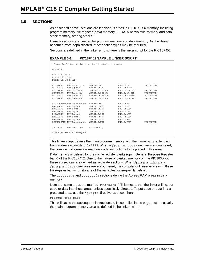
MPLAB® C18 C Compiler Getting Started
6.5 SECTIONS
As described above, sections are the various areas in PIC18XXXX memory, including program memory, file register (data) memory, EEDATA nonvolatile memory and data stack memory, among others.
Usually sections are needed for program memory and data memory. As the design becomes more sophisticated, other section types may be required.
Sections are defined in the linker scripts. Here is the linker script for the PIC18F452:
EXAMPLE 6-1: PIC18F452 SAMPLE LINKER SCRIPT
This linker script defines the main program memory with the name page extending from address 0x002A to 0x7FFF. When a #pragma code directive is encountered, the compiler will generate machine code instructions to be placed in this area.
Data memory is defined for the six file register banks (gpr = General Purpose Register bank) of the PIC18F452. Due to the nature of banked memory on the PIC18XXXX, these six regions are defined as separate sections. When #pragma udata and #pragma idata directives are encountered, the compiler will reserve areas in these file register banks for storage of the variables subsequently defined.
The accessram and accesssfr sections define the Access RAM areas in data memory.
Note that some areas are marked “PROTECTED”. This means that the linker will not put code or data into those areas unless specifically directed. To put code or data into a protected area, use the #pragma directive as shown here:
#pragma code page
This will cause the subsequent instructions to be compiled in the page section, usually the main program memory area as defined in the linker script.
// Sample linker script for the PIC18F452 processor
LIBPATH .
FILES c018i.oFILES clib.libFILES p18f452.lib
CODEPAGE NAME=vectors START=0x0 END=0x29 PROTECTEDCODEPAGE NAME=page START=0x2A END=0x7FFFCODEPAGE NAME=idlocs START=0x200000 END=0x200007 PROTECTEDCODEPAGE NAME=config START=0x300000 END=0x30000D PROTECTEDCODEPAGE NAME=devid START=0x3FFFFE END=0x3FFFFF PROTECTEDCODEPAGE NAME=eedata START=0xF00000 END=0xF000FF PROTECTED
ACCESSBANK NAME=accessram START=0x0 END=0x7FDATABANK NAME=gpr0 START=0x80 END=0xFFDATABANK NAME=gpr1 START=0x100 END=0x1FFDATABANK NAME=gpr2 START=0x200 END=0x2FFDATABANK NAME=gpr3 START=0x300 END=0x3FFDATABANK NAME=gpr4 START=0x400 END=0x4FFDATABANK NAME=gpr5 START=0x500 END=0x5FFACCESSBANK NAME=accesssfr START=0xF80 END=0xFFF PROTECTED
SECTION NAME=CONFIG ROM=config
STACK SIZE=0x100 RAM=gpr5
DS51295F-page 96 © 2005 Microchip Technology Inc.
Architecture
6.6 SFRS, TIMERS SW/HW
The PIC18XXXX Special Function Registers (SFRs) are special registers in the file register area of the microcontroller. These include the core registers, such as the Stack Pointer, STATUS register and Program Counter of the microprocessor core, as well as the registers to control the various peripherals. The peripherals include such things as input and output pins, timers, USARTs and registers to read and write the EEDATA areas of the device. MPLAB C18 can access these registers by name, and they can be read and written like a variable defined in the application. Use caution, though, because some of the Special Function Registers have characteristics different from variables. Some have only certain bits available, some are read-only and some may affect other registers or device operation when accessed.
6.6.1 I/O Registers
Input and output on the PIC18XXXX pins is accomplished by reading and writing the registers associated with the port pins on the device. Check the data sheet for available ports on the device. There are three Special Function Registers associated with each port. One called a TRIS register defines the direction of the port pin: input or output. A second register, called the PORT register, is used to read and write values to the port pin, and a third, named LAT, is a latch which allows reading and writing the values on the port without actually reading the current state of the pins on the port. This is important in the PIC18XXXX architecture because of read-modify-write considerations. The contents of I/O port registers should not be treated like variable storage – they operate quite differently. See the data sheets for more information.
Some pins are multiplexed and may need to be configured by other Special Function Registers before they can be used as digital I/O. Specifically, PORTA on many PIC18XXXX devices can also be used as analog inputs to the A/D converter.
To configure and use PORTB as 4 input pins and 4 output pins, the following code could be written in MPLAB C18:
6.6.2 Hardware Timers
PIC18XXXX timers are also configured and accessed through Special Function Registers. Most PIC18XXXX devices have at least three timers. For instance, Timer0 in the PIC18F452 is configured through the T0CON register, and its counter/timer values can be read from, and written to, using the two 8-bit registers, TMR0L and TMR0H. The INTCON register has bits which can be used to set Timer0 as an interrupt, and controls whether the timer counts from the oscillator or from an external signal, thereby acting as a counter.
6.6.3 Software Timers
As in any C program, delays and timing loops can be created in software. Consideration of the design will affect how software and hardware timers are employed. A typical software delay loop involves setting up a counter and decrementing until it reaches zero. The disadvantages of a software timer is that if interrupts are occurring, the delays of a software timer will be extended and possibly become unpredictable. Additionally, the program can do nothing except respond to interrupts while processing a software delay loop.
TRISB = 0xF0 /* configure PORTB as 4 input pins, bits 4-7 and 4 output pins, bits 0-3 */
PORTB = 0x0C /* set pins 0 and 1 low, pins 2 and 3 high */
© 2005 Microchip Technology Inc. DS51295F-page 97

MPLAB® C18 C Compiler Getting Started
6.7 INTERRUPTS
Interrupts are a feature of the PIC18XXXX core. Timers, I/O pins, USARTs, A/Ds and other peripherals can cause interrupts. When an interrupt occurs, the code in the application is suspended and code in the interrupt routine executes. When the Interrupt Service Routine finishes, it executes a “return from interrupt” instruction and the program returns to where it left off.
There are two kinds of interrupts in the PIC18XXXX, low priority and high priority. Which kind of interrupt to use is one of the decisions that go into the design of the application. MPLAB C18 can be used for both types of interrupts, but the designer must be aware of the details of the particular interrupt operation in order to retain the contents of some of the critical internal registers. Careful consideration of variable usage and libraries (especially if used in the interrupt routine) is essential.
When an interrupt occurs, a low priority interrupt saves only the PC (Program Counter register). For high priority interrupts, the PIC18XXXX core automatically saves the PC, WREG, BSR and STATUS registers. See the MPLAB® C18 C Compiler User’s Guide section on “ISR Context Saving” for information on saving application variables during interrupts.
6.8 MATH AND I/O LIBRARIES
MPLAB C18 has libraries for control of peripherals, for software implementation of peripherals, for general data handling and for mathematical functions. See MPLAB® C18 C Compiler Libraries (DS51297) for a full description of these libraries.
The source code is provided for these libraries so they can be customized and rebuilt with modifications required by the application.
The use of the peripheral libraries usually requires an understanding of the operation of the peripherals as described in the device data sheets. Using C libraries results in reduced complexity when initializing and using the peripherals.
The MPLAB C18 math libraries include floating-point operations, trigonometric operations and other operations. When using floating-point and complex mathematical functions on 8-bit embedded controllers, care should be taken to evaluate whether the operations are an efficient choice for the particular design. Often, a table, a table with an interpolation, or an approximation using other methods will provide enough accuracy for the task. A 32-bit floating-point operation will typically take many hundreds of cycles to execute and may consume significant portions of program memory space.
DS51295F-page 98 © 2005 Microchip Technology Inc.
MPLAB® C18 C COMPILER
GETTING STARTEDChapter 7. Troubleshooting
7.1 INTRODUCTION
This chapter covers common error messages that might be encountered when getting started with MPLAB C18. It also provides answers to Frequently Asked Questions (FAQs).
Error Messages
• EM-1 Linker error: “name exceeds file format maximum of 62 characters”• EM-2 Linker error: “could not find file ‘c018i.o’”• EM-3 Compiler error: “Error [1027] unable to locate ‘p18cxxx.h’”• EM-4 Compiler error: “Error [1105] symbol ‘symbol-name’ has not been defined.”• EM-5 MPLAB IDE error: “Skipping link step. The project contains no linker script.”• EM-6 Compiler error: Syntax Error• EM-7 Linker error: “Could not find definition of symbol...”
Frequently Asked Questions (FAQs)
• FAQ-1 Are the proper MPLAB IDE components installed to use MPLAB C18?• FAQ-2 What needs to be set to show the printf() statements in the Output window?• FAQ-3 How can a global structure/union be declared in one place so ‘extern’
declarations don’t need to be added in all of the .c files that reference it?• FAQ-4 Why is “Warning [2066] type qualifier mismatch in assignment” being issued?• FAQ-5 When I dereference a pointer to a string, the result is not the first character of
that string. Why?• FAQ-6 Where are code examples on using a low priority interrupt?• FAQ-7 Can a 16-bit variable be used to access the 16-bit Timer SFRs (e.g., TMR1L
and TMR1H)?• FAQ-8 How do I fix “unable to fit section” error for data memory sections?• FAQ-9 How do I fix “unable to fit section” error for program memory sections?• FAQ-10 How do I create a large object in data memory (> 256 bytes)?• FAQ-11 How do I put data tables into program memory?• FAQ-12 How do I copy data from program memory to data memory?• FAQ-13 How do I set Configuration bits in C?• FAQ-14 What references exist for setting Configuration bits in C?• FAQ-15 How do I use printf with string literals?• FAQ-16 When I perform arithmetic on two characters and assign it to an integer, I do
not get the expected result. Why not?
© 2005 Microchip Technology Inc. DS51295F-page 99
MPLAB® C18 C Compiler Getting Started
7.2 ERROR MESSAGES
EM-1 Linker error: “name exceeds file format maximum of 62 characters”
Select Project>Build Options…>Project MPLINK tab and check the box, Suppress Cod-file generation. The COD file is an older format and is no longer needed.
EM-2 Linker error: “could not find file ‘c018i.o’”
Enter the proper directory path in Project>Build Options…>Project General tab. Set the Library Path box to “C:\mcc18\lib”. c018i.o is the start-up library for MPLAB C18. It sets up the stack, initializes variables, then jumps to main() in the application.
EM-3 Compiler error: “Error [1027] unable to locate ‘p18cxxx.h’”
Enter the proper directory path in Project>Build Options…>Project General tab. Set the Include Path box to “C:\mcc18\h”. p18cxxx.h is the generic header file that includes the selected processor’s processor-specific header file.
EM-4 Compiler error: “Error [1105] symbol ‘symbol-name’ has not been defined”
If the symbol-name is a Special Function Register (e.g., TRISB), make sure to include the generic processor header file (#include <p18cxxx.h>) or the processor-specific include file (e.g., #include <p18f452.h>). Special Function Registers are declared in the processor-specific header file. Also, ensure that the Special Function Register is in all capital letters (i.e., TRISB instead of trisb), as C language is case-sensitive and the Special Function Registers are declared with all capital letters.
If the symbol-name is not a Special Function Register, make sure to define the symbol previous to its use and that the symbol name is correctly typed.
EM-5 MPLAB IDE error: “Skipping link step. The project contains no linker script.”
Make sure a linker script is in the project. Linker scripts are in the lkr subdirectory of the MPLAB C18 install.
EM-6 Compiler error: Syntax Error
This is usually a typographical error in the source code. Double click on this error line in the Output window to bring up the MPLAB Editor with the cursor on the line that caused the error. Usually the color coded syntax will display the error.
EM-7 Linker error: “Could not find definition of symbol...”
This can be caused by using the wrong linker script. Linker scripts for MPLAB C18 include other library files. Make sure to use the linker scripts in the lkr subdirectory of the MPLAB C18 install.
The project builds OK but when the linker tries to link, the following error is displayed:
Error - could not find definition of symbol 'putsMYFILE' in file 'C:\My Projects\myfile.o'.Errors : 1
It may be that a C file has the same name as an assembly file, even though they have different extensions. Look carefully at the Output window to see if it’s trying to generate two “.o” files with the same name. This is effectively like omitting the first file from the project. Rename files so that they don’t share the same name.
DS51295F-page 100 © 2005 Microchip Technology Inc.
Troubleshooting
7.3 FREQUENTLY ASKED QUESTIONS (FAQS)
FAQ-1 Are the proper MPLAB IDE components installed to use MPLAB C18?
Here is how to check installed components:
Go to the Windows Start menu and browse to the Microchip folder and choose MPLAB>Set Up MPLAB Tools to verify the proper components are installed. See Figure 1-1 for the minimum IDE installation selections required for the MPLAB C18.
FAQ-2 What needs to be set to show the printf() statements in the Output window?
In the MPLAB IDE, select Debugger>Select Tool>MPLAB SIM to enable the simulator and access the debugger menu. Then select Debugger>Settings and click on the Uart1 I/O tab. Make sure that the “Enable Uart1 I/O” is selected and the Window option is selected for Output (see Figure 3-15).
FAQ-3 How can a global structure/union be declared in one place so ‘extern’ declarations don’t need to be added in all of the .c files that reference it?
Create a typedef in a header file:
typedef union { struct { unsigned char Outstanding_Comms_Req:1; }; unsigned char All_Flags;} RS485_t;
Then, in one of your .c files use:
RS485_t RS485_Flags;
to define your union, and in your other .c files you would use:
extern RS485_t RS485_Flags;
Additionally, you could place the extern in a header file, then include it in your .c files.
FAQ-4 Why is “Warning [2066] type qualifier mismatch in assignment” being issued?
The libraries distributed with MPLAB C18 are compiled using the large code model (-ml command-line option). By default, MPLAB IDE and the compiler compile applica-tions for the small code model. For example, the printf function distributed with the compiler expects to receive a “const far rom char *”, but the application is actually sending a “const near rom char *” to the printf function when the large code model is not selected for the application. This difference between far and near is causing the “type qualifier mismatch in assignment” warning. To get rid of these warnings, do one of three things:
1. Recompile the libraries distributed with MPLAB C18 using the small code model (only recommended if all applications will be using the small code model);
2. Enable the large code model in the IDE for the particular application (may increase code size); or
3. Cast the constant character string to a constant far rom character pointer, as in: printf ((const far rom char *)”This is a test\n\r”);
© 2005 Microchip Technology Inc. DS51295F-page 101

MPLAB® C18 C Compiler Getting Started
FAQ-5 When I dereference a pointer to a string, the result is not the first character of that string. Why?
const char *path = "file.txt";while(*path) // while end of string not found{ path++; length++;}
MPLAB C18 stores constant literal strings in program memory. However, path is a pointer to data memory. When path is dereferenced, it will access data memory instead of program memory. Add the rom keyword to make the pointer point to a ROM location instead of RAM.
const rom char *path = "file.txt";
FAQ-6 Where are code examples on using a low priority interrupt?
See the #pragma interruptlow and the “Examples” chapter in the MPLAB® C18 C Compiler User’s Guide.
FAQ-7 Can a 16-bit variable be used to access the 16-bit Timer SFRs (e.g., TMR1L and TMR1H)?
Do not combine TMR1H and TMR1L in a 16-bit variable to access the timer. The order in which the two Special Function Registers are read and written is critical because the full 16-bit timer is only read/written when the TMR1L register is read/written. If the com-piler happens to write TMR1L before TMR1H, the high byte of the timer will not be loaded with the data written to TMR1H. Similarly, which byte the compiler reads first is not controllable.
FAQ-8 How do I fix “unable to fit section” error for data memory sections?
MPLAB C18 provides two different section types for data memory:
• udata – contains statically allocated uninitialized user variables• idata – contains statically allocated initialized user variables
A default section exists for each section type in MPLAB C18 (e.g., .udata_foobar.o).
For example, given the following source code located in foobar.c:
unsigned char foo[255]; int bar; void main (void) { while (1) ; }
This code would result in the following error:
Error – section ‘.udata_foobar.o’ can not fit the section. Section ‘.udata_foobar.o’ length = 0x00000101.
DS51295F-page 102 © 2005 Microchip Technology Inc.

Troubleshooting
There are two ways to resolve this error:
1. Split foobar.c into multiple files: foo.c unsigned char foo[255]; void main (void) { while (1) ; }
bar.c int bar;
2. Use the #pragma udata directive to create a separate section to contain the variables foo and bar:
foobar.c #pragma udata foo unsigned char foo[255]; #pragma udata bar int bar; void main (void) { while (1) ; }
FAQ-9 How do I fix “unable to fit section” error for program memory sections?
MPLAB C18 provides two different section types for program memory:
• code – contains executable instructions• romdata – contains variables and constants
By default, MPLAB IDE only enables those optimizations that do not affect debugging. To reduce the amount of program memory used by the code sections, enable all opti-mizations. To enable in the MPLAB IDE, select Project>Build options…>Project, click the MPLAB C18 tab and set Categories: Optimization to enable all.
© 2005 Microchip Technology Inc. DS51295F-page 103

MPLAB® C18 C Compiler Getting Started
FAQ-10 How do I create a large object in data memory (> 256 bytes)?
By default, MPLAB C18 assumes that an object will not cross a bank boundary. The following steps are required to safely use an object that is larger than 256 bytes:
1. The object must be allocated into its own section using the #pragma idata or #pragma udata directive:
#pragma udata buffer_scn static char buffer[0x180]; #pragma udata
2. Accesses to the object must be done via a pointer: char * buf_ptr = &buffer[0]; ... // examples of use buf_ptr[5] = 10; if (buf_ptr[275] > 127) ...
3. A region that spans multiple banks must be created in the linker script:- Linker script before modification:
DATABANK NAME=gpr2 START=0x200 END=0x2FF DATABANK NAME=gpr3 START=0x300 END=0x3FF
- Linker script after modification: DATABANK NAME=big START=0x200 END=0x37F PROTECTED DATABANK NAME=gpr3 START=0x380 END=0x3FF
4. The object’s section (created in Step 1) must be assigned into the new region (created in Step 3) by adding a SECTION directive to the linker script:
SECTION NAME=buffer_scn RAM=big
FAQ-11 How do I put data tables into program memory?
By default, MPLAB C18 puts user variables in data memory. The rom qualifier is used to denote that the object is located in program memory:
rom int array_of_ints_in_rom[] = { 0, 1, 2, 3, 4, 5 }; rom int * q = &array_of_ints_in_rom[0];
In the above example, array_of_ints_in_rom is an array of integers located in pro-gram memory. The q is a pointer that can be used to loop through the elements of the array.
DS51295F-page 104 © 2005 Microchip Technology Inc.

Troubleshooting
FAQ-12 How do I copy data from program memory to data memory?
For pointer types, use one of the following standard library functions:
For non-pointer types, a direct assignment can be made.
Examples:
rom int rom_int = 0x1234; ram int ram_int; rom char * rom_ptr = “Hello, world!”; ram char ram_buffer[14]; void main(void) { ram_int = rom_int; strcpypgm2ram (ram_buffer, rom_ptr); }
FAQ-13 How do I set Configuration bits in C?
MPLAB C18 provides the #pragma config directive for setting Configuration bits in C.
Examples of use:
/* Oscillator Selection: HS */ #pragma config OSC = HS /* Enable watchdog timer and set postscaler to 1:128 */ #pragma config WDT = ON, WDTPS=128
FAQ-14 What references exist for setting Configuration bits in C?
• MPLAB® C18 C Compiler User’s Guide contains a general description of the #pragma config directive.
• PIC18 Configuration Settings Addendum contains all available Configuration settings and values for all PIC18 devices.
• MPLAB C18 --help-config command-line option lists the available Configuration settings and values of standard output for a specific device.
Function Description
memcpypgm2ram Copy a buffer from ROM to RAM
memmovepgm2ram Copy a buffer from ROM to RAM
strcatpgm2ram Append a copy of the source string located in ROM to the end of the destination string located in RAM
strcpypgm2ram Copy a string from RAM to ROM
strncatpgm2ram Append a specified number of characters from the source string located in ROM to the end of the destination string located in RAM
strncpypgm2ram Copy characters from the source string located in ROM to the destination string located in RAM
© 2005 Microchip Technology Inc. DS51295F-page 105
MPLAB® C18 C Compiler Getting Started
FAQ-15 How do I use printf with string literals?
Since string literals are stored in program memory, an MPLAB C18 specific conversion operator (%S) was added to handle output of characters from a program memory array (rom char []):
#include <stdio.h>rom char * foo = “Hello, world!”;void main (void){ printf (“%S\n”, foo); printf (“%S\n”, “Hello, world!”);}
When outputting a far program memory array (far rom char []), make sure to use the H size specifier (i.e., %HS):
#include <stdio.h>far rom char * foo = “Hello, world!”;void main (void){ printf (“%HS\n”, foo);}
FAQ-16 When I perform arithmetic on two characters and assign it to an integer, I do not get the expected result. Why not?
Given the following example:
unsigned char a, b;unsigned int i;a = b = 0x80;i = a + b;
ANSI/ISO expects i to be equal to 0x100, but MPLAB C18 sets i equal to 0x00.
By default, MPLAB C18 will perform arithmetic at the size of the largest operand, even if both operands are smaller than an int. To enable the ISO mandated behavior that all arithmetic be performed at int precision or greater, use the -Oi command-line option. To enable in the MPLAB IDE, select Project>Build options…>Project, click the MPLAB C18 tab and select Enable integer promotions.
DS51295F-page 106 © 2005 Microchip Technology Inc.
MPLAB® C18 C COMPILER
GETTING STARTEDGlossary
Absolute Section
A section with a fixed (absolute) address that cannot be changed by the linker.
Access Memory
Special registers on PIC18 devices that allow access regardless of the setting of the Bank Select Register (BSR).
Address
Value that identifies a location in memory.
Alphabetic Character
Alphabetic characters are those characters that are letters of the arabic alphabet(a, b, …, z, A, B, …, Z).
Alphanumeric
Alphanumeric characters are comprised of alphabetic characters and decimal digits (0, 1, …, 9).
Anonymous Structure
An unnamed structure that is a member of a C union. The members of an anonymous structure may be accessed as if they were members of the enclosing union. For exam-ple, in the following code, hi and lo are members of an anonymous structure inside the union caster:
union castaway int intval; struct { char lo; //accessible as caster.lo char hi; //accessible as caster.hi };} caster;
ANSI
American National Standards Institute is an organization responsible for formulating and approving standards in the United States.
Application
A set of software and hardware that may be controlled by a PICmicro microcontroller.
Archive
A collection of relocatable object modules. It is created by compiling/assembling multi-ple source files to object files, and then using the archiver to combine the object files into one library file. A library can be linked with object modules and other libraries to create executable code.
Archiver
A tool that creates and manipulates libraries.
© 2005 Microchip Technology Inc. DS51295F-page 107
MPLAB® C18 C Compiler Getting Started
ASCII
American Standard Code for Information Interchange is a character set encoding that uses 7 binary digits to represent each character. It includes upper and lower case letters, digits, symbols and control characters.
Assembler
A language tool that translates assembly language source code into machine code.
Assembly Language
A programming language that describes binary machine code in a symbolic form.
Assigned Section
A section which has been assigned to a target memory block in the linker command file.
Asynchronous Events
Multiple events that do not occur at the same time. This is generally used to refer to interrupts that may occur at any time during processor execution.
Asynchronous Stimulus
Data generated to simulate external inputs to a simulator device.
Binary
The base two numbering system that uses the digits 0-1. The right-most digit counts ones, the next counts multiples of 2, then 22 = 4, etc.
Breakpoint, Hardware
An event whose execution will cause a Halt.
Breakpoint, Software
An address where execution of the firmware will halt. Usually achieved by a special break instruction.
Build
Compile and link all the source files for an application.
C
A general-purpose programming language which features economy of expression, modern control flow, data structures and a rich set of operators.
Calibration Memory
A Special Function Register or Registers used to hold values for calibration of a PICmicro microcontroller on-board RC oscillator or other device peripherals.
Central Processing Unit
The part of a device that is responsible for fetching the correct instruction for execution, decoding that instruction and then executing that instruction. When necessary, it works in conjunction with the Arithmetic Logic Unit (ALU) to complete the execution of the instruction. It controls the program memory address bus, the data memory address bus and accesses to the stack.
COFF
Common Object File Format. An object file of this format contains machine code, debugging and other information.
Command Line Interface
A means of communication between a program and its user based solely on textual input and output.
DS51295F-page 108 © 2005 Microchip Technology Inc.

Glossary
Compiler
A program that translates a source file written in a high-level language into machine code.
Conditional Compilation
The act of compiling a program fragment only if a certain constant expression, specified by a preprocessor directive, is true.
Configuration Bits
Special purpose bits programmed to set PICmicro microcontroller modes of operation. A Configuration bit may or may not be preprogrammed.
Control Directives
Directives in assembly language code that cause code to be included or omitted based on the assembly time value of a specified expression.
CPU
See Central Processing Unit.
Cross Reference File
A file that references a table of symbols and a list of files that references the symbol. If the symbol is defined, the first file listed is the location of the definition. The remaining files contain references to the symbol.
Data Directives
Data directives are those that control the assembler’s allocation of program or data memory and provide a way to refer to data items symbolically; that is, by meaningful names.
Data Memory
On Microchip MCU and DSC devices, data memory (RAM) is comprised of General Purpose Registers (GPRs) and Special Function Registers (SFRs). Some devices also have EEPROM data memory.
Device Programmer
A tool used to program electrically programmable semiconductor devices, such as microcontrollers.
Digital Signal Controller
A microcontroller device with digital signal processing capability (i.e., Microchip dsPIC® devices).
Directives
Statements in source code that provide control of the language tool’s operation.
Download
Download is the process of sending data from a host to another device, such as an emulator, programmer or target board.
DSC
See Digital Signal Controller.
EEPROM
Electrically Erasable Programmable Read-Only Memory. A special type of PROM that can be erased electrically. Data is written or erased one byte at a time. EEPROM retains its contents even when power is turned off.
Emulation
The process of executing software loaded into emulation memory as if it were firmware residing on a microcontroller device.
© 2005 Microchip Technology Inc. DS51295F-page 109
MPLAB® C18 C Compiler Getting Started
Emulation Memory
Program memory contained within the emulator.
Emulator
Hardware that performs emulation.
Emulator System
The MPLAB ICE 2000 and 4000 emulator systems include the pod, processor module, device adapter, cables and MPLAB IDE software.
Endianess
Describes order of bytes in a multibyte object.
Environment – IDE
The particular layout of the desktop for application development.
Environment – MPLAB PM3
A folder containing files on how to program a device. This folder can be transferred to a SD™/MMC card.
EPROM
Erasable Programmable Read-Only Memory. A programmable read-only memory that can be erased, usually by exposure to ultraviolet radiation.
Error File
A file containing error messages and diagnostics generated by a language tool.
Event
A description of a bus cycle which may include address, data, pass count, external input, cycle type (fetch, R/W) and time-stamp. Events are used to describe triggers, breakpoints and interrupts.
Export
Send data out of the MPLAB IDE in a standardized format.
Extended Microcontroller Mode
In Extended Microcontroller mode, on-chip program memory, as well as external mem-ory, is available. Execution automatically switches to external if the program memory address is greater than the internal memory space of the PIC17 or PIC18 device.
Extended Mode
In Extended mode, the compiler will utilize the extended instructions (i.e., ADDFSR, ADDULNK, CALLW, MOVSF, MOVSS, PUSHL, SUBFSR and SUBULNK) and the Indexed with Literal Offset Addressing mode.
External Label
A label that has external linkage.
External Linkage
A function or variable has external linkage if it can be referenced from outside the module in which it is defined.
External Symbol
A symbol for an identifier which has external linkage. This may be a reference or a definition.
DS51295F-page 110 © 2005 Microchip Technology Inc.

Glossary
External Symbol Resolution
A process performed by the linker in which external symbol definitions from all input modules are collected in an attempt to resolve all external symbol references. Any external symbol references which do not have a corresponding definition cause a linker error to be reported.
External Input Line
An external input signal logic probe line (TRIGIN) for setting an event based upon external signals.
External RAM
Off-chip read/write memory.
Fatal Error
An error that will halt compilation immediately. No further messages will be produced.
File Registers
On-chip data memory, including General Purpose Registers (GPRs) and Special Function Registers (SFRs).
Filter
Determined by selection what data is included/excluded in a trace display or data file.
Flash
A type of EEPROM where data is written or erased in blocks instead of bytes.
FNOP
Forced No Operation. A forced NOP cycle is the second cycle of a two-cycle instruction. Since the PICmicro microcontroller architecture is pipelined, it prefetches the next instruction in the physical address space while it is executing the current instruction. However, if the current instruction changes the Program Counter, this prefetched instruction is explicitly ignored, causing a forced NOP cycle.
Frame Pointer
A pointer that references the location on the stack that separates the stack-based arguments from the stack-based local variables. Provides a convenient base from which to access local variables and other values for the current function.
Free-Standing
A C compiler implementation that accepts any strictly conforming program that does not use complex types and in which the use of the features specified in the ISO library clause is confined to the contents of the standard headers, <float.h>, <iso646.h>, <limits.h>, <stddef.h> and <stdint.h>.
GPR
General Purpose Register. The portion of device data memory (RAM) available for general use.
Halt
A stop of program execution. Executing Halt is the same as stopping at a breakpoint.
Hex Code
Executable instructions stored in a hexadecimal format code. Hex code is contained in a hex file.
Hex File
An ASCII file containing hexadecimal addresses and values (hex code) suitable for programming a device.
© 2005 Microchip Technology Inc. DS51295F-page 111

MPLAB® C18 C Compiler Getting Started
Hexadecimal
The base 16 numbering system that uses the digits 0-9 plus the letters A-F (or a-f). The digits A-F represent hexadecimal digits with values of (decimal) 10 to 15. The right-most digit counts ones, the next counts multiples of 16, then 162 = 256, etc.
High-Level Language
A language for writing programs that is further removed from the processor than assembly.
ICD
In-Circuit Debugger. MPLAB ICD 2 is Microchip’s in-circuit debugger.
ICE
In-Circuit Emulator. MPLAB ICE 2000 and 4000 are Microchip’s in-circuit emulators.
IDE
Integrated Development Environment. MPLAB IDE is Microchip’s integrated development environment.
IEEE
Institute of Electrical and Electronics Engineers.
Import
Bring data into the MPLAB IDE from an outside source, such as from a hex file.
Instruction Set
The collection of machine language instructions that a particular processor understands.
Instruction
A sequence of bits that tells a central processing unit to perform a particular operation and can contain data to be used in the operation.
Internal Linkage
A function or variable has internal linkage if it can not be accessed from outside the module in which it is defined.
International Organization for Standardization
An organization that sets standards in many businesses and technologies, including computing and communications.
Interrupt
A signal to the CPU that suspends the execution of a running application and transfers control to an Interrupt Service Routine (ISR) so that the event may be processed.
Interrupt Handler
A routine that processes special code when an interrupt occurs.
Interrupt Request
An event which causes the processor to temporarily suspend normal instruction execution and to start executing an interrupt handler routine. Some processors have several interrupt request events allowing different priority interrupts.
Interrupt Service Routine
User-generated code that is entered when an interrupt occurs. The location of the code in program memory will usually depend on the type of interrupt that has occurred.
IRQ
See Interrupt Request.
DS51295F-page 112 © 2005 Microchip Technology Inc.

Glossary
ISO
See International Organization for Standardization.
ISR
See Interrupt Service Routine.
Latency
The time between an event and its response.
Librarian
See Archiver.
Library
See Archive.
Linker
A language tool that combines object files and libraries to create executable code, resolving references from one module to another.
Linker Script Files
Linker script files are the command files of a linker. They define linker options and describe available memory on the target platform.
Listing Directives
Listing directives are those directives that control the assembler listing file format. They allow the specification of titles, pagination and other listing control.
Listing File
A listing file is an ASCII text file that shows the machine code generated for each C source statement, assembly instruction, assembler directive or macro encountered in a source file.
Little Endianess
A data ordering scheme for multibyte data, whereby the Least Significant Byte is stored at the lower addresses.
Local Label
A local label is one that is defined inside a macro with the LOCAL directive. These labels are particular to a given instance of a macro’s instantiation. In other words, the symbols and labels that are declared as local are no longer accessible after the ENDM macro is encountered.
Logic Probes
Up to 14 logic probes can be connected to some Microchip emulators. The logic probes provide external trace inputs, trigger output signal, +5V, and a common ground.
Machine Code
The representation of a computer program that is actually read and interpreted by the processor. A program in binary machine code consists of a sequence of machine instructions (possibly interspersed with data). The collection of all possible instructions for a particular processor is known as its “instruction set”.
Machine Language
A set of instructions for a specific central processing unit, designed to be usable by a processor without being translated.
Macro
Macro instruction. An instruction that represents a sequence of instructions in abbreviated form.
© 2005 Microchip Technology Inc. DS51295F-page 113

MPLAB® C18 C Compiler Getting Started
Macro Directives
Directives that control the execution and data allocation within macro body definitions.
Make Project
A command that rebuilds an application, recompiling only those source files that have changed since the last complete compilation.
MCU
Microcontroller Unit. An abbreviation for microcontroller; also μC.
Memory Models
A description that specifies the size of pointers that point to program memory.
Message
Text displayed to alert you to potential problems in language tool operation. A message will not stop operation.
Microcontroller
A highly integrated chip that contains a CPU, RAM, program memory, I/O ports and timers.
Microcontroller Mode
One of the possible program memory configurations of PIC17 and PIC18 micro-controllers. In Microcontroller mode, only internal execution is allowed. Thus, only the on-chip program memory is available in Microcontroller mode.
Microprocessor Mode
One of the possible program memory configurations of PIC17 and PIC18 micro-controllers. In Microprocessor mode, the on-chip program memory is not used. The entire program memory is mapped externally.
Mnemonics
Text instructions that can be translated directly into machine code. Also referred to as opcodes.
MPASM Assembler
Microchip Technology’s relocatable macro assembler for PICmicro microcontroller devices, KEELOQ® devices and Microchip memory devices.
MPLAB ICD 2
Microchip’s in-circuit debugger that works with MPLAB IDE. The ICD supports Flash devices with built-in debug circuitry. The main component of each ICD is the module. A complete system consists of a module, header, demo board, cables and MPLAB IDE software.
MPLAB ICE 2000/4000
Microchip’s in-circuit emulators that works with MPLAB IDE. MPLAB ICE 2000 sup-ports PICmicro MCUs. MPLAB ICE 4000 supports PIC18F MCUs and dsPIC30F DSCs. The main component of each ICE is the pod. A complete system consists of a pod, processor module, cables and MPLAB IDE software.
MPLAB IDE
Microchip’s Integrated Development Environment.
MPLAB PM3
A device programmer from Microchip. Programs PIC18 microcontrollers and dsPIC® digital signal controllers. Can be used with MPLAB IDE or stand-alone. Will obsolete PRO MATE® II.
DS51295F-page 114 © 2005 Microchip Technology Inc.

Glossary
MPLAB SIM
Microchip’s simulator that works with MPLAB IDE in support of PICmicro MCU and dsPIC DSC devices.
MPLIB Object Librarian
MPLIB librarian is an object librarian for use with COFF object modules created using either MPASM assembler (mpasm or mpasmwin v2.0) or MPLAB C1X C compilers.
MPLINK Object Linker
MPLINK linker is an object linker for the Microchip MPASM assembler and the Microchip MPLAB C17 or C18 C compilers. MPLINK linker also may be used with the Microchip MPLIB librarian. MPLINK linker is designed to be used with MPLAB IDE, though it does not have to be.
MRU
Most Recently Used. Refers to files and windows available to be selected from MPLAB IDE main pull-down menus.
Nesting Depth
The maximum level to which macros can include other macros.
Node
MPLAB IDE project component.
Non-Extended Mode
In Non-Extended mode, the compiler will not utilize the extended instructions nor the Indexed with Literal Offset Addressing mode; also referred to as “Traditional” mode.
Non Real Time
Refers to the processor at a breakpoint or executing single-step instructions or MPLAB IDE being run in Simulator mode.
Non-Volatile Storage
A storage device whose contents are preserved when its power is off.
NOP
No Operation. An instruction that has no effect when executed except to advance the Program Counter.
Object Code
The machine code generated by an assembler or compiler.
Object File
A file containing machine code and possibly debug information. It may be immediately executable or it may be relocatable, requiring linking with other object files (e.g., libraries) to produce a complete executable program.
Object File Directives
Directives that are used only when creating an object file.
Octal
The base 8 number system that only uses the digits 0-7. The right-most digit counts ones, the next digit counts multiples of 8, then 8^2 = 64, etc.
Off-Chip Memory
Off-chip memory refers to the memory selection option for the PIC17 or PIC18 device where memory may reside on the target board, or where all program memory may be supplied by the emulator.
© 2005 Microchip Technology Inc. DS51295F-page 115

MPLAB® C18 C Compiler Getting Started
Opcodes
Operational Codes. See Mnemonics.
Operators
Symbols, like the plus sign ‘+’ and the minus sign ‘-’, that are used when forming well-defined expressions. Each operator has an assigned precedence that is used to determine order of evaluation.
OTP
One-Time-Programmable. EPROM devices that are not in windowed packages. Since EPROM needs ultraviolet light to erase its memory, only windowed devices are erasable.
Pass Counter
A counter that decrements each time an event (such as the execution of an instruction at a particular address) occurs. When the pass count value reaches zero, the event is satisfied. You can assign the Pass Counter to break and trace logic, and to any sequential event in the complex trigger dialog.
PC
Personal Computer or Program Counter.
PC Host
Any IBM® or compatible personal computer running a supported Windows operating system.
PICmicro MCUs
PICmicro microcontrollers (MCUs) refers to all Microchip microcontroller families.
PICSTART Plus
A developmental device programmer from Microchip. Programs 8-, 14-, 28- and 40-pin PICmicro microcontrollers. Must be used with MPLAB IDE Software.
Pod, Emulator
The external emulator box that contains emulation memory, trace memory, event and cycle timers, and trace/breakpoint logic.
Power-on Reset Emulation
A software randomization process that writes random values in data RAM areas to simulate uninitialized values in RAM upon initial power application.
Pragma
A directive that has meaning to a specific compiler. Often a pragma is used to convey implementation-defined information to the compiler. MPLAB C30 uses attributes to convey this information.
PRO MATE II
A device programmer from Microchip. Programs most PICmicro microcontrollers as well as most memory and KEELOQ devices. Can be used with MPLAB IDE or stand-alone.
Profile
For MPLAB SIM simulator, a summary listing of executed stimulus by register.
Program Counter
The location that contains the address of the instruction that is currently executing.
Program Memory
The memory area in a device where instructions are stored. Also, the memory in the emulator or simulator containing the downloaded target application firmware.
DS51295F-page 116 © 2005 Microchip Technology Inc.

Glossary
Project
A set of source files and instructions to build the object and executable code for an application.
Prototype System
A term referring to a user’s target application or target board.
PWM Signals
Pulse-Width Modulation Signals. Certain PICmicro MCU devices have a PWM peripheral.
Qualifier
An address or an address range used by the Pass Counter or as an event before another operation in a complex trigger.
Radix
The number base, hex or decimal, used in specifying an address.
RAM
Random Access Memory (data memory). Memory in which information can be accessed in any order.
Raw Data
The binary representation of code or data associated with a section.
Real Time
When released from the Halt state in the Emulator or MPLAB ICD mode, the processor runs in Real-Time mode and behaves exactly as the normal chip would behave. In Real-Time mode, the real-time trace buffer of MPLAB ICE is enabled and constantly captures all selected cycles, and all break logic is enabled. In the emulator or MPLAB ICD, the processor executes in real time until a valid breakpoint causes a Halt, or until the user halts the emulator. In the simulator, real time simply means execution of the microcontroller instructions as fast as they can be simulated by the host CPU.
Recursive Calls
A function that calls itself, either directly or indirectly.
Recursion
The concept that a function or macro, having been defined, can call itself. Great care should be taken when writing recursive macros; it is easy to get caught in an infinite loop where there will be no exit from the recursion.
Reentrant
A function that may have multiple, simultaneously active instances. This may happen due to either direct, or indirect recursion, or through execution during interrupt processing.
Relocatable
An object file whose sections have not been assigned to a fixed location in memory.
ROM
Read-Only Memory (program memory). Memory that cannot be modified.
Run
The command that releases the emulator from Halt, allowing it to run the application code and change or respond to I/O in real time.
Runtime Model
Describes the use of target architecture resources.
© 2005 Microchip Technology Inc. DS51295F-page 117

MPLAB® C18 C Compiler Getting Started
Scenario
For MPLAB SIM simulator, a particular setup for stimulus control.
Section
A named sequence of code or data.
Section Attribute
A characteristic ascribed to a section (e.g., an access section).
SFR
See Special Function Registers.
Simulator
A software program that models the operation of devices.
Single Step
This command steps though code, one instruction at a time. After each instruction, MPLAB IDE updates register windows, watch variables and status displays, so you can analyze and debug instruction execution. You can also single step C compiler source code, but instead of executing single instructions, MPLAB IDE will execute all assembly level instructions generated by the line of the high-level C statement.
Skew
The information associated with the execution of an instruction appears on the processor bus at different times. For example, the executed opcodes appear on the bus as a fetch during the execution of the previous instruction. The source data address and value and the destination data address appear when the opcodes are actually exe-cuted, and the destination data value appears when the next instruction is executed. The trace buffer captures the information that is on the bus at one instance. Therefore, one trace buffer entry will contain execution information for three instructions. The number of captured cycles from one piece of information to another for a single instruction execution is referred to as the skew.
Skid
When a hardware breakpoint is used to Halt the processor, one or more additional instructions may be executed before the processor Halts. The number of extra instructions executed after the intended breakpoint is referred to as the skid.
Source Code
The form in which a computer program is written by the programmer. Source code is written in some formal programming language which can be translated into machine code or executed by an interpreter.
Source File
An ASCII text file containing source code.
Special Function Registers
The portion of data memory (RAM) dedicated to registers that control I/O processor functions, I/O status, timers or other modes or peripherals.
Stack, Hardware
Locations in PICmicro microcontroller where the return address is stored when a function call is made.
Stack, Software
Memory used by an application for storing return addresses, function parameters and local variables. This memory is typically managed by the compiler when developing code in a high-level language.
DS51295F-page 118 © 2005 Microchip Technology Inc.

Glossary
Static RAM or SRAM
Static Random Access Memory. Program memory you can read/write on the target board that does not need refreshing frequently.
Status Bar
The Status Bar is located on the bottom of the MPLAB IDE window and indicates such current information as cursor position, Development mode and device, and active toolbar.
Step Into
This command is the same as Single Step. Step Into (as opposed to Step Over) follows a CALL instruction into a subroutine.
Step Over
Step Over allows you to step over subroutines. This command executes the code in the subroutine and then stops execution at the return address to the subroutine.
When stepping over a CALL instruction, the next breakpoint will be set at the instruction after the CALL. If for some reason the subroutine gets into an endless loop, or does not return properly, the next breakpoint will never be reached. Select Halt to regain control of program execution.
Step Out
Step Out allows you to step out of a subroutine which you are currently stepping through. This command executes the rest of the code in the subroutine and then stops execution at the return address to the subroutine.
Stimulus
Input to the simulator (i.e., data generated to exercise the response of simulation to external signals). Often, the data is put into the form of a list of actions in a text file. Stimulus may be asynchronous, synchronous (pin), clocked and register.
Stopwatch
A counter for measuring execution cycles.
Storage Class
Determines the lifetime of an object.
Storage Qualifier
Indicates special properties of an object (e.g., volatile).
Symbol
A symbol is a general purpose mechanism for describing the various pieces which comprise a program. These pieces include function names, variable names, section names, file names, struct/enum/union tag names, etc. Symbols in MPLAB IDE refer mainly to variable names, function names and assembly labels. The value of a symbol after linking is its value in memory.
System Window Control
The system window control is located in the upper left corner of windows and some dialogs. Clicking on this control usually pops up a menu that has the items “Minimize”, “Maximize” and “Close”.
Target
Refers to user hardware.
Target Application
Software residing on the target board.
© 2005 Microchip Technology Inc. DS51295F-page 119

MPLAB® C18 C Compiler Getting Started
Target Board
The circuitry and programmable device that makes up the target application.
Target Processor
The microcontroller device on the target application board.
Template
Lines of text that you build for inserting into your files at a later time. The MPLAB Editor stores templates in template files.
Tool Bar
A row or column of icons that you can click on to execute MPLAB IDE functions.
Trace
An emulator or simulator function that logs program execution. The emulator logs program execution into its trace buffer which is uploaded to the MPLAB IDE Trace window.
Trace Memory
Trace memory contained within the emulator. Trace memory is sometimes called the trace buffer.
Trigger Output
Trigger output refers to an emulator output signal that can be generated at any address or address range, and is independent of the trace and breakpoint settings. Any number of trigger output points can be set.
Uninitialized Data
Data which is defined without an initial value. In C,int myVar; defines a variable which will reside in an uninitialized data section.
Upload
The upload function transfers data from a tool, such as an emulator or programmer, to the host PC or from the target board to the emulator.
Vector
The memory locations from which an application starts execution when a specific event occurs, such as a Reset or interrupt.
Warning
An alert that is provided to warn you of a situation that would cause physical damage to a device, software file or equipment.
Watch Variable
A variable that you may monitor during a debugging session in a Watch window.
Watch Window
Watch windows contain a list of watch variables that are updated at each breakpoint.
Watchdog Timer
A timer on a PICmicro microcontroller that resets the processor after a selectable length of time. The WDT is enabled or disabled and set up using Configuration bits.
WDT
See Watchdog Timer.
Workbook
For MPLAB SIM simulator, a setup for generation of SCL stimulus.
DS51295F-page 120 © 2005 Microchip Technology Inc.

MPLAB® C18 C COMPILERGETTING STARTED
Index
Symbols#pragma Directive.................................................... 94.HEX........................................................................... 9_mplink.exe ......................................................... 13
AAdd Files to Project .................................................. 28Application Notes ....................................................... 6Arrays....................................................................... 79
BBreakpoints .............................................................. 51Build ........................................................................... 9Build Options............................................................ 33Build Project ............................................................. 35
CConfiguration Bits................................................... 105Configuration Memory.............................................. 94Copy Data .............................................................. 105Could not find definition of symbol ......................... 100Could not find file 'c018i.o' ..................................... 100Customer Change Notification Service ...................... 7Customer Support ...................................................... 7
DData EEPROM Memory........................................... 94Data Memory ........................................................... 92Data Tables............................................................ 104Data Types............................................................... 76Debug Toolbar ......................................................... 37Default Storage Class .............................................. 60Demo Board............................................................. 55Design Centers .......................................................... 6Diagnostic Level....................................................... 60Documentation Conventions...................................... 3
EEnable Integer Promotions ...................................... 61Error Messages........................................................ 99
Could not find definition of symbol .................. 100Could not find file 'c018i.o' .............................. 100Name exceeds...62 characters ....................... 100Symbol 'symbol-name' has not been defined . 100Syntax Error ...............................................43, 100Unable to locate 'p18cxxx.h' ........................... 100
Examples ................................................................. 20Executables ..................................................12, 13, 20Execution Flow......................................................... 14Extended Mode.............................................13, 61, 94
FFrequently Asked Questions (FAQs) ....................... 99
GGeneral Options ....................................................... 60
HHardware Timers...................................................... 97Header Files
Assembly .................................................... 12, 20Standard C.................................................. 12, 20
Hex........................................................................... 13
II/O Registers ............................................................ 97Inherit Global Settings.............................................. 61Installation Directory................................................. 18Installing MPLAB C18 .............................................. 15Internet Address......................................................... 7Interrupts .................................................................. 98
LLanguage Tool Locations......................................... 30Language Tool Setup............................................... 27Language Tools ....................................................... 13Language Tools Execution
Flow .................................................................. 14Libraries ........................................................12, 20, 98License Agreement .................................................. 16Linker Scripts ..................................................... 12, 20Low Priority Interrupt .............................................. 102
MMacro Definitions ..................................................... 61Make .......................................................................... 9Map Files.................................................................. 86MCC_INCLUDE ......................................................... 22mcc18.exe .............................................................. 13Memory Model ......................................................... 62Microchip Web Site .................................................... 7Mouse Over Variable ............................................... 46mp2hex.exe............................................................ 13MPASM Assembler .................................................. 12MPASM Cross-Assembler ....................................... 10mpasmwin.exe ....................................................... 13MPLAB C18 Compiler Installation............................ 13MPLAB ICD 2........................................................... 55MPLAB IDE Components......................................... 11mplib.exe .............................................................. 13MPLINK Linker ................................................... 10, 13mplink.exe............................................................ 13
© 2005 Microchip Technology Inc. DS51295F-page 121

MPLAB® C18 C Compiler Getting Started
NName exceeds...maximum of 62 characters .......... 100Non-Extended Mode ................................................ 13
OOptimizations ........................................................... 63
PPATH Environment Variable .................................... 22PICDEM 2 Plus Demo Board ................................... 56Pointers .................................................................... 82printf .................................................................. 106Procedural Abstraction Passes ................................ 63Program Memory...................................................... 90Project ...................................................................... 25Project Build Options................................................ 59Project Window ........................................................ 30Project Wizard.......................................................... 26
RRecommended Reading............................................. 4Requirements ........................................................... 11Resolve Problems .................................................... 43Return Address Stack .............................................. 93Right Mouse Menu ................................................... 50
SSections ................................................................... 96Simulator Settings .................................................... 49Software Timers ....................................................... 97Source Code ............................................................ 12
Processor-Specific Libraries ............................. 20Standard C Libraries ......................................... 20
Special Function Registers....................................... 93Start-up Code........................................................... 94Stopwatch ................................................................ 50String...................................................................... 102Structures................................................................. 80Symbol 'symbol-name' has not been defined......... 100Syntax Error ..................................................... 43, 100System Requirements .............................................. 11
TTextbooks................................................................... 5Treat ’char’ as Unsigned......................................... 61Type Qualifier Mismatch in Assignment ........... 43, 101
UUnable to locate 'p18cxxx.h' ................................... 100Uninstalling MPLAB C18 .......................................... 24Use Alternate Settings.............................................. 61
WWarnings
Type Qualifier Mismatch in Assignment.... 43, 101Watch Window ......................................................... 47
DS51295F-page 122 © 2005 Microchip Technology Inc.

Index
NOTES:
© 2005 Microchip Technology Inc. DS51295F-page 123
DS51295F-page 124 © 2005 Microchip Technology Inc.
AMERICASCorporate Office2355 West Chandler Blvd.Chandler, AZ 85224-6199Tel: 480-792-7200 Fax: 480-792-7277Technical Support: http://support.microchip.comWeb Address: www.microchip.com
AtlantaAlpharetta, GA Tel: 770-640-0034 Fax: 770-640-0307
BostonWestborough, MA Tel: 774-760-0087 Fax: 774-760-0088
ChicagoItasca, IL Tel: 630-285-0071 Fax: 630-285-0075
DallasAddison, TX Tel: 972-818-7423 Fax: 972-818-2924
DetroitFarmington Hills, MI Tel: 248-538-2250Fax: 248-538-2260
KokomoKokomo, IN Tel: 765-864-8360Fax: 765-864-8387
Los AngelesMission Viejo, CA Tel: 949-462-9523 Fax: 949-462-9608
San JoseMountain View, CA Tel: 650-215-1444Fax: 650-961-0286
TorontoMississauga, Ontario, CanadaTel: 905-673-0699 Fax: 905-673-6509
ASIA/PACIFICAustralia - SydneyTel: 61-2-9868-6733 Fax: 61-2-9868-6755
China - BeijingTel: 86-10-8528-2100 Fax: 86-10-8528-2104
China - ChengduTel: 86-28-8676-6200 Fax: 86-28-8676-6599
China - FuzhouTel: 86-591-8750-3506 Fax: 86-591-8750-3521
China - Hong Kong SARTel: 852-2401-1200 Fax: 852-2401-3431
China - QingdaoTel: 86-532-8502-7355Fax: 86-532-8502-7205
China - ShanghaiTel: 86-21-5407-5533 Fax: 86-21-5407-5066China - ShenyangTel: 86-24-2334-2829Fax: 86-24-2334-2393
China - ShenzhenTel: 86-755-8203-2660 Fax: 86-755-8203-1760
China - ShundeTel: 86-757-2839-5507 Fax: 86-757-2839-5571
China - WuhanTel: 86-27-5980-5300Fax: 86-27-5980-5118
China - XianTel: 86-29-8833-7250Fax: 86-29-8833-7256
ASIA/PACIFICIndia - BangaloreTel: 91-80-2229-0061 Fax: 91-80-2229-0062
India - New DelhiTel: 91-11-5160-8631Fax: 91-11-5160-8632
India - PuneTel: 91-20-2566-1512Fax: 91-20-2566-1513
Japan - YokohamaTel: 81-45-471- 6166 Fax: 81-45-471-6122
Korea - GumiTel: 82-54-473-4301Fax: 82-54-473-4302
Korea - SeoulTel: 82-2-554-7200Fax: 82-2-558-5932 or 82-2-558-5934
Malaysia - PenangTel: 604-646-8870Fax: 604-646-5086
Philippines - ManilaTel: 632-634-9065Fax: 632-634-9069
SingaporeTel: 65-6334-8870Fax: 65-6334-8850
Taiwan - Hsin ChuTel: 886-3-572-9526Fax: 886-3-572-6459
Taiwan - KaohsiungTel: 886-7-536-4818Fax: 886-7-536-4803
Taiwan - TaipeiTel: 886-2-2500-6610 Fax: 886-2-2508-0102
Thailand - BangkokTel: 66-2-694-1351Fax: 66-2-694-1350
EUROPEAustria - WeisTel: 43-7242-2244-399Fax: 43-7242-2244-393Denmark - CopenhagenTel: 45-4450-2828 Fax: 45-4485-2829
France - ParisTel: 33-1-69-53-63-20 Fax: 33-1-69-30-90-79
Germany - MunichTel: 49-89-627-144-0 Fax: 49-89-627-144-44
Italy - Milan Tel: 39-0331-742611 Fax: 39-0331-466781
Netherlands - DrunenTel: 31-416-690399 Fax: 31-416-690340
Spain - MadridTel: 34-91-352-30-52Fax: 34-91-352-11-47
UK - WokinghamTel: 44-118-921-5869Fax: 44-118-921-5820
WORLDWIDE SALES AND SERVICE
08/24/05