Embed Size (px)
Citation preview

MPC-LS Platform Board User Guide
1. Introduction
This document is user guide for MPC-LS Platform Board. This board along with the MPC-LS Processor Module enables new gateway use cases and Service-oriented Gateways. The EVB is targeted at providing a platform for evaluation and development of the automotive MCU, facilitating hardware and software development and debug. For a complete development environment, a debugger, compiler and hardware interface is required. This board is fully supported by NXP. This Manual includes system setup and debugging, and provides detailed information on the overall design and usage of the platform board from a Hardware Systems perspective. Normal temperature specification components are used on the EVB (+70°C) to alleviate potential component availability problems and to keep the overall design cost down. ROHS compliant components and materials are used throughout the EVB.
1. Introduction ........................................................................ 1 2. Board Overview ................................................................. 2
2.1. Modular Concept & Interconnect............................ 2 2.2. MPC-LS Platform Board block diagram ................. 2 2.3. MPC-LS Platform Board features ........................... 4
3. MPC-LS Platform Board peripherals ................................. 4 3.1. MPC-LS Processor Module to MPC-LS Platform
Board Interface ..................................................................... 4 3.2. Power Supply .......................................................... 4 3.3. Debug...................................................................... 5 3.4. Ethernet ................................................................... 6
3.4.1. RGMII Ethernet Switch ................................... 6 3.4.2. RGMII Ethernet Card Connector ..................... 6 3.4.3. Additional RGMII Signals ............................... 6
3.5. SERDES PCIe & Ethernet ...................................... 6 3.5.1. SERDES 0 Lanes 0 & 1; .................................. 6 3.5.2. SERDES 1 Lane 0; Ethernet (SGMII) ............. 6 3.5.3. SERDES 0 Lane 1; PCIe End Point ................. 7
3.6. CAN-FD Physical Interfaces .................................. 7 3.7. FlexRay Physical Interfaces .................................... 7 3.8. LIN Physical Interfaces ........................................... 7 3.9. GPIO/ADC Breakout & Arduino Header Area ....... 8
3.9.1. Arduino Header Connections ........................... 8 3.9.2. GPIO Breakout ................................................ 9 3.9.3. ADC Breakout ................................................. 9

Error! No text of specified style in document., Error! No text of specified style in document., Error! No text of specified style in document., Error! No text of specified style in document.
2 NXP Semiconductors
COMPANY PROPRIETARY
INTERNAL USE ONLY
2. Board Overview
This MPC-LS Platform Board is a platform designed to enable new gateway use cases and service-oriented gateways. The modular design of the MPC-LS VNP EVB enables the processor module to be swapped out in the future to support future gateway solutions using the same platform board.
2.1. Modular Concept & Interconnect
A modular EVB hardware system is designed consisting of:
a. A common platform board that provides access to common communication interfaces and I/O.
b. A device specific processor board with memory and debug interfaces. The processor board also can be used in a standalone mode in addition to connection to the platform board.
Top and bottom connectors are used to connect processor board with platform board. These interconnects are used for signal/power connections between the boards. Any other processor board to be used with platform board must match interconnect.
An example is shown below.
Figure 1. Interconnect between MPC-LS Platform Board and MPC-LS Processor Module.
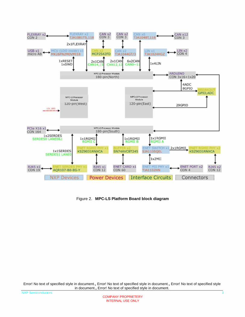
2.2. MPC-LS Platform Board block diagram
Error! No text of specified style in document., Error! No text of specified style in document., Error! No text of specified style in document., Error! No text of specified style in document.
NXP Semiconductors 3
COMPANY PROPRIETERY
INTERNAL USE ONLY
Figure 2. MPC-LS Platform Board block diagram

Error! No text of specified style in document., Error! No text of specified style in document., Error! No text of specified style in document., Error! No text of specified style in document.
4 NXP Semiconductors
COMPANY PROPRIETARY
INTERNAL USE ONLY
2.3. MPC-LS Platform Board features
Figure 3. MPC-LS Platform Board with MPC-LS Processor Module
3. MPC-LS Platform Board peripherals
3.1. MPC-LS Processor Module to MPC-LS Platform Board Interface
The signal and power are shared between MPC-LS Platform Board and MPC-LS Processor Module. Any processor board must follow requirements for the interface connector are covered.
3.2. Power Supply
A 12V barrel connector and switch is available on MPC-LS Platform Board and this supply is also routed to the MPC-LS Processor Module interconnector.

Error! No text of specified style in document., Error! No text of specified style in document., Error! No text of specified style in document., Error! No text of specified style in document.
NXP Semiconductors 5
COMPANY PROPRIETERY
INTERNAL USE ONLY
Figure 4. Power Tree
Switch SW1 is available to power the MPC-LS Platform Board using 12V input supply. There are two options to provide 12V input using P3 power connector and J50. Following power rails are generated on MPC-LS Platform Board, each power supply has an indicator LED
Power supply Regulator
LED indicator Jumper
Test Point
3.3V U15 J52 TP8
5V U14 D27 J51 TP14
0.85V U17 D34 J58 TP13
2.1V U18 D37 J57 TP12
1.8V U59 D516 J113 TP532
1.2V U16 D30 J53 TP10
3.3. Debug
An integrated “OpenSDA Interface” debug solution is provided on the MPC-LS Platform Board.

Error! No text of specified style in document., Error! No text of specified style in document., Error! No text of specified style in document., Error! No text of specified style in document.
6 NXP Semiconductors
COMPANY PROPRIETARY
INTERNAL USE ONLY
Zero ohm resistors are present to allow disconnection of the OpenSDA interface from the JTAG lines so that an external probe can be used on the MPC-LS Processor Module. This facility is also be added for the UART0 lines to allow the LIN0 transceiver to selected instead.
3.4. Ethernet
3.4.1. RGMII Ethernet Switch
The signals labelled RGMII_A on the interconnect from the MPU will connect to the RGMII interface on an NXP SJA1105R/S automotive Ethernet switch. Two of the ports on the switch will connect to automotive Ethernet PHYs using an NXP TJA1102. The other two ports are connected to KSZ9031RNXCAs to connect to RJ45 sockets
3.4.2. RGMII Ethernet Card Connector
An Ethernet MPC-LS Processor Module connector is planned for the signals labelled RGMII_B on the interconnect from the MPU board. Interface for this connector supports many NXP ethernet PHY card.
3.4.3. Additional RGMII Signals
Additional signals labelled RGMII_C are included on the interconnect, This Port is connected to KSZ9031 which further connects to RJ45 connector for extended ethernet connectivity.
3.5. SERDES PCIe & Ethernet
3.5.1. SERDES 0 Lanes 0 & 1;
SERDES0 lane 0 and 1 connections are routed to a standard (x16) PCIe host connector, however this connector might be used for SGMII functionality on SERDES0 lane 0, hence an additional sideband connector is also given to carry the additional control signals required to interface, for example, to an additional SJA1105R/S or the planned SJA1110 in the future.
3.5.2. SERDES 1 Lane 0; Ethernet (SGMII)
The SERDES1 lane 0 connections routed from the MPU will connect to a 2.5Gbps capable SGMII based physical interface.

Error! No text of specified style in document., Error! No text of specified style in document., Error! No text of specified style in document., Error! No text of specified style in document.
NXP Semiconductors 7
COMPANY PROPRIETERY
INTERNAL USE ONLY
3.5.3. SERDES 0 Lane 1; PCIe End Point
SERDES1 lane 1 is kept unconnected, as a usecase processor card will use this lane to connect card as Endpoint to any MCU.
3.6. CAN-FD Physical Interfaces
The MPC-LS Platform Board has 6 high speed CAN transceivers using NXP TJA1048 devices. Each device supports two channel, so 12 CAN channels are implemented on 6 TJA1048.TJA1048 implements the CAN physical layer as defined in ISO 11898-2:2016 and SAE J2284-1 to SAE J2284-5. This implementation enables reliable communication in the CAN FD fast phase at data rates up to 5 Mbit/s. CAN13 and CAN15 are using TJA1044 device, it is a single channel device and it is specified for data rates up to 1 Mbit/s. CAN14 and CAN15 signals will be connected to 8Mpbs capable physical interfaces, one potential device is the Microchip MPC2542. Outputs from the CAN transceivers (CANH, CANL and GND signals) are connected to a standard 3 pin 0.1” header. Jumpers are available to allow the MPU CANTX and CANRX signals to be isolated from the CAN driver if required. Jumpers also allows control of the standby inputs on the transceivers.
3.7. FlexRay Physical Interfaces
A FlexRay interface is included utilizing two TJA1081 devices, and connectors. Jumpers are available to allow the MPU FlexRay TXD, TXEN and RXD signals to be isolated from the FlexRay driver if required.
3.8. LIN Physical Interfaces
Four LIN interfaces are provided using the NXP TJA1024 transceiver with 2x2 Molex Connectors. Jumpers are also available to allow the MPU UART0/LIN0 signals to be isolated from the LIN driver if required, and also to allow the routing of LIN0 debug signals.

Error! No text of specified style in document., Error! No text of specified style in document., Error! No text of specified style in document., Error! No text of specified style in document.
8 NXP Semiconductors
COMPANY PROPRIETARY
INTERNAL USE ONLY
3.9. GPIO/ADC Breakout & Arduino Header Area
A GPIO/ADC breakout area and Arduino header connections is available to allow the user to access GPIO and ADC lines and connect additional hardware, for example a secure element to support encryption/decryption.
3.9.1. Arduino Header Connections
The Arduino compatible header will share the same layout as connectors J2, J3, J13 and J14 on the DEVKIT-MPC5748G board, as in the picture below. The signals labelled GPIO_Jxx-xx in the schematic are ruted to the corresponding signals on the Arduino compatible header. The UART signals on GPIO_J2-01 and GPIO_J2-03 are shared with the LIN1 signals via a jumper selector.
Power and GND should also be supplied to the Arduino header in the same way as the DEVKIT-MPC5748G and the graphic below. Note that the PER_HVA rail will be fixed at 3.3V in this case as the 16FFC devices do not support 5V IO.

Error! No text of specified style in document., Error! No text of specified style in document., Error! No text of specified style in document., Error! No text of specified style in document.
NXP Semiconductors 9
COMPANY PROPRIETERY
INTERNAL USE ONLY
3.9.1.1. Arduino Header Placement
Arduino header connectors can directly connect NCJ38A shield which provides the secure element can be connected. See picture below.
3.9.2. GPIO Breakout
An additional GPIO area consisting of 0.1” pitch headers will be provided for the signals labelled GPIO_Yxx in the schematic.
3.9.3. ADC Breakout
The pins labelled ADC_x in the schematic are connected to 0.1” pitch header in an ADC breakout area.
Error! No text of specified style in document., Error! No text of specified style in document., Error! No text of specified style in document., Error! No text of specified style in document.
10 NXP Semiconductors
COMPANY PROPRIETARY
INTERNAL USE ONLY
A variable resistor will be included and headers available such that this can be linked to any of the available ADC inputs. The VREFH and VREFL connections will also be connected to jumpers connecting them to 1.8V and GND respectively, but allowing an option to supply externally.


Error! No text of specified style in document. Error! No text of specified style in document. Error! No text of specified style in document.
How to Reach Us:
Home Page:
nxp.com
Web Support:
nxp.com/support
Information in this document is provided solely to enable system and software
implementers to use NXP products. There are no express or implied copyright licenses
granted hereunder to design or fabricate any integrated circuits based on the
information in this document. NXP reserves the right to make changes without further
notice to any products herein.
NXP makes no warranty, representation, or guarantee regarding the suitability of its
products for any particular purpose, nor does NXP assume any liability arising out of
the application or use of any product or circuit, and specifically disclaims any and all
liability, including without limitation consequential or incidental damages. “Typical”
parameters that may be provided in NXP data sheets and/or specifications can and do
vary in different applications, and actual performance may vary over time. All operating
parameters, including “typicals,” must be validated for each customer application by
customer’s technical experts. NXP does not convey any license under its patent rights
nor the rights of others. NXP sells products pursuant to standard terms and conditions
of sale, which can be found at the following address: nxp.com/SalesTermsandConditions.
NXP, the NXP logo, NXP SECURE CONNECTIONS FOR A SMARTER WORLD,
COOLFLUX, EMBRACE, GREENCHIP, HITAG, I2C BUS, ICODE, JCOP, LIFE VIBES,
MIFARE, MIFARE CLASSIC, MIFARE DESFire, MIFARE PLUS, MIFARE FLEX,
MANTIS, MIFARE ULTRALIGHT, MIFARE4MOBILE, MIGLO, NTAG, ROADLINK,
SMARTLX, SMARTMX, STARPLUG, TOPFET, TRENCHMOS, UCODE, Freescale, the
Freescale logo, AltiVec, C 5, CodeTEST, CodeWarrior, ColdFire, ColdFire+, C Ware,
the Energy Efficient Solutions logo, Kinetis, Layerscape, MagniV, mobileGT, PEG,
PowerQUICC, Processor Expert, QorIQ, QorIQ Qonverge, Ready Play, SafeAssure, the
SafeAssure logo, StarCore, Symphony, VortiQa, Vybrid, Airfast, BeeKit, BeeStack,
CoreNet, Flexis, MXC, Platform in a Package, QUICC Engine, SMARTMOS, Tower,
TurboLink, and UMEMS are trademarks of NXP B.V. All other product or service names
are the property of their respective owners. ARM, AMBA, ARM Powered, Artisan,
Cortex, Jazelle, Keil, SecurCore, Thumb, TrustZone, and μVision are registered
trademarks of ARM Limited (or its subsidiaries) in the EU and/or elsewhere. ARM7,
ARM9, ARM11, big.LITTLE, CoreLink, CoreSight, DesignStart, Mali, mbed, NEON,
POP, Sensinode, Socrates, ULINK and Versatile are trademarks of ARM Limited (or its
subsidiaries) in the EU and/or elsewhere. All rights reserved. Oracle and Java are
registered trademarks of Oracle and/or its affiliates. The Power Architecture and
Power.org word marks and the Power and Power.org logos and related marks are
trademarks and service marks licensed by Power.org.
© 2017 NXP B.V.
COMPANY PROPRIETARY INTERNAL USE ONLY