Embed Size (px)
Citation preview

MPC 75 MPCAIRCRAFT
SYSTEM DEFINITIO

MPCAIRCRAFT
MPC 75
SYSTEM DEFINITION
MPCAircraftGmbH ReleasedKreetslag 102103 Hamburg 95West-GermanyJET-E System EngineeringRef: EE-T-90/025September 1990

SYSTEM DEFINITION MPCAIRCRAFT
CONTENTS
21 -Airconditioning22-Autoflight23-Communication24 - Electrical power25 - Equipment/Furnishing26-Fireprotection27-Flight controls28 - Fuel29-Hydraulic power30 - Ice and rain protection
31 - Instrumentation/Recording32-Landinggear33-Lights34 - Navigation35 - Oxygen36 - Pneumatic38 - Water/Waste45 - On-board maintenance49-Airborne auxiliary power70-Engine controls

ABBREVIATIONS MPCAIRCRAFT
A
AC
ACARS
ACMS
ACP
ACU
ADF
ADMADS
AFT
Ah
AHRSALT
AMM
AOA
APU
ATC
B
BAT
BFE
BITEBMC
BRT
BSCU
CAA
GAB
CAPT
CAUTCDU
CFDSCIDS
CMC
CMS
CONDCPM
CSM/G
ASendantSeat
Altemaling CurrentARINCCommunicationAddressing
and Reporting SystemAircraft Condittonirtg Monitoring
System
Audio Control Panel
APU Control Unit
Automatic Direction Flndlng
Air Data Module
Air Data System
Afterward
Ampere-hour
Attitüde Headlng Reference System
Attitüde
Aircraft Maintenance ManualAngle of Attack
Auxiliary Power Unit
Air Trafflc Control
Blue
Battery
Buyer Furnlshed Equipment
Built-in Test Equipment
Bleed Air Monitoring Computer
Brighl
Brake and Steering Control Unit
Civil Aviation Authority
Cabin
Captain
CautionControl Display Unit
Centralized Fault Display System
Cabin Integrated Data System
Centralized Maintenance Computer
Centralized Maintenance SystemCondtöon
Computer Modules
Constant Speed Motor/Generator
CTL
CU
CuR
DC
DET
DEU
DFDR
DME
DMPDU
ECAM
ECS
ECU
EE(E/E)
EFCSEFIS
EISEIVMUEIUELACELEV
ELSE M ERG
ENG
ESS
E/WD
EXT
FAC
FADEC
FBW
FCGC
FCU
FDIU
FL
Control
Control Unit
Cubtc Feet
Dkect Current
Oatectlon
Decoder/Encoder
Digital Flight Data Recorder
Distance Measuring Equipment
Display Management Processor
Display Unit
Electronic Centralized Aircraft Monttoring
Environmental Control System
Engine Control Unit
Electconic/ElectricalElectronic Flight Control System
Electronic Flight Instrument System
Electronic Instrument System
Engine Interface Vibration Monitoring Unit
Engine Interface UnitElevator Alleren ComputerElevation
Electronic Library SystemEmergencyEngine
Essential
Engine/Warning Display
External
Flight Augmentation Computer
Füll Authority Digital Engine Control System
Fly-By-Wire
Ftight Control and Guidance Computer
Flight Control Unit
Flight Data Interface Unit
Flight
FMCFMGC
FMSF/0
FQCC
FOIC
FQMS
FSDUFWDFWS
GGGCUGLC
GPCUGPSGPWS
GRDGS
H
h
HF
HP
HS
HYDR
ICAO
DG
ILS
in
IOM
IPC
IRS
Flight Management ComputerFlight Management and
Guidance ComputerFlight Management SystemFirst OfffcerFuel Quantity ControlComputerFuel Quantity Indication ControlFuel Quantity MeasuringSystemFlre Source Detection UnitForwardFlight Warning System
GalleyGreenGenerator Control Unit
Generator Une ContactorGround Power Control UnitGlobal Positioning SystemGround Proximity WarningSystemGroundGlide Slope
Hfch
hour
High Frequertcy
High Pressure
High Speed
Hydraulic
International Civil Aviation
Organisation
Integrated Drive Generator
Instrument Landing System
inch
Input and Output Modulea
Illustrated Parts Catalog
Inertial Relerence System
Page:1

ABBREVIATIONS MPCAIRCRAFT
L Lavatofy
1
LA
b
LCD
LOG
LGCIU
LH
LOC
LP
LRU1 TLT
M
MAGN
MCDU
MCU
MDDU
MEL
MKR
MLI
MLS
MSU
MAI
NAV
ND
NCd
OMS
PCU
PFD
Ph
PSM
litre/liter
Linear Accelerometer
Pound
Liquid Crystal Display
Landing
Landing Gear Control Interface
Unit
LeftHand
Locallzer
Low Pressure
Une Replaceable Unit
Ught
Motor
Magnete
MuWpurpose Control Display Unit
Modular Concept Unit
Multipurpose Disk Drive Unit
Minimum Equipment List
Marker
Magnetic Level Indicator
Microwave Landing System
Mode Selector Unit
Nacelle Anti Ice
Navigation
Navigation Display
Nickel Cadmium
On-Board Maintenance System
Power Control Unit
Prima/v Flight Display
Phase
Power Supply Module
PSU
PWR
QAR
RA/RALT
RATRFRHRMCU
RMPRS-232
S
SATCOM
SD
SEC
SEL
SELCAL
SERV
SFCC
TAS
TAT
TDB
TCAS
TH3
TLA
TRU
US
USgal
VHP
Passenger Service Unit VOR VHF Omnidirectional Range
Power v/s Vertical Speed
Quick Access Recorder w Wardrobe
W WidthRadio Altimeter ,„ . . . ... _ . . .
WAG Waming Acquisition ConcentratorsRam Air TurbineRadio Frequency *AI Wing Anti Ice
Right Hand WXfl Weather Radar
Remote Magnetic Compensation
Unit Y YellowRadio Management Panel
Seviell Data Bus Standard
Stowage
Satellite Communicatkxi
System Display
Spoiler Elevator Computer
Setect
Selective Calling
Servo
Slat and Flap Control Computer
True Air Speed
Total Air Temperature
To-Be-Determtned
Traffic Collison Alert and
Avoidance System
Trimabto Horizontal Stabttlfzer
ThrotHe Lever Angle
Transformer Rectifier Unit
United States
United States gallon
Very High Frequency
Page :2

ENVIRONMENTAL CONTROL SYSTEM MPCAIRCRAFT
Contents
1- Air conditioning System
2 - Cabin pressure control System
21

ENVIRONMENTAL CONTROL SYSTEM MPCAIRCRAFT
Air conditioning pack schematic
MAIN HEAT
EXCHANGE
RAM AIR
OUTLET
NACA INLET
WATER
wirciim
WATER
EXIRACTOR
GROUND COOLING FAN + CHECK VALVE
21
Figure 21-2September 1990 Page: 21.03

ENVIRONMENTAL CONTROL SYSTEM MPCAIRCRAFT
Air distribution
MAIN SUPPLY DUCTS
RISER DUCTS
7 PER SIDE IN WING AREA
21INDIVIDUAL
AIR SUPPLY
COCKPIT SUPPLY
MAIN SUPPLY DUCTS
METERING RESTRICTOR
CABIN AMBIENT AIRTO UNDERFLOOR AREA
September 1990Figure21-3
Page:21.04

ENVIRONMENTAL CONTROL SYSTEM <§> MPCAIRCRAFT
21
2 - Cabin pressure control System
The cabin pressure control System controls the cabin pressure and the change rate to provide
maximum passenger comfort and safety.
The pressure control System consists of an automatic System and a manual standby System
to control the outflow valve.
Provision for an optional second pressure Controller isprovided (seefigure21-4). Excessive
positive or negative cabin overpressure is prevented by two pneumatically controlled safety valves.
Automatic prepressurisation to prevent sudden pressure fluctuation (bumps) on take off and
landing, is provided in AUTO mode.
September 1 990 Page :21 >05

ENVIRONMENTAL CONTROL SYSTEM MPCAIRCRAFT
Cabin pressurisation control schematic 21
AIR DATA
SYSTEM
PRESSURISATIONCONIROLLER 1
PRESSURISATIONCONTROLLER 2
(OPTION)
PRESSURISED AREA
GABMAN V/S CTL MODE SEL
lOU7FLOW VALVE
(BUT1EHFLY TYPE)
SAFET*VALVES
y HUIUU UUlVt(3RD MOfܫ OPTIONAL)
0 0 0 0 0 0 0 0 0 0 0 0 0 0 0 0 0 0 0 0 0 0 0 0 0 0 0 0 0 0 0
UNPRESSURISED AREA
September 1990Figure 21-4
Page: 21.06
AUTO FLIGHT MPCAIRCRAFT
22
Contents
- General
- Flight management
- Auto flight

AUTO FLIGHT €> MPCAIRCRAFT
Auto Flight Modes - General 22
• AP/FD can either be selected at the flight control unit (FCU)
or provided by the FMS according to active flightplan
• Basic Flight Control mode is always in accordance with the electrical flight control System (EFCS)
and always engaged

AUTO FLIGHT MPCAIRCRAFT
Autopilot / Flight Director Modes
Selectable upper modes
1. Longitudinal Modes
22
- altitude hold- altitude acquire-flight levelchange- profile- climb- descent-flight path angle
ALTALT ACQFLCHPROFCLBDESFPA
Lateral Modes
- heading- track- navigation (incl. VOR)
HDGTRKNAV
3. Approach Modes
- approach- go around- take-off- localiser
APPRGATOLOG

AUTO FLIGHT MPCAIRCRAFT
Autothrust Modes
• A/THR permanently armed
• Autothrust modes in association to autopilot / flight director mode
AP/FD
ALT, ALT ACQ, FPA
DES, CLB, PROF
FLCH
APPR -FINAL-G/S-FLARE
TO/GA
A/THR modes
SPD/MACH
SPD/MACH, THR
THR
SPDSPDRETARD
A/THR functionoverridden
SPD / MACH speed/mach mode selectable
THR thrust mode, limit thrust according to selected thrust rating
Alpha Floor Protection overrides all modes with GA limit thrust if A/C flight envelope is exceeded

AUTO Fl IfiHT W MPCM U l \J rLIvan l " AIRCRAFT
Flight Management System (FMS) 22• The aircraft is equipped with a single Flight Management System,
with a second Flight Management Computer available äs an option.
• The system is controlled via two Multipurpose Control and Display Units (MCDU). Many frequent
and complex tasks are performed by the Flight Management Computer to
increase safety and punctuality of the flights.
Flight Planning / Flight Plan Execution
Take-off and Landing Data/Cruise Speed Calculation
Radio tuning / Radio navigation
On-board Maintenance System (QMS) support
Data link function (ACARS)
In case of failure of the flight management Computer, the MCDUs have to perform
a back-up function for navigation tasks, such äs radio navigation.
September 1990 Page :22.01

AUTO FLIGHT MPCAIRCRAFT
Flight managementSystem architecture
,September 1990
FLIGHT MANAGEMENT
COMPUTER
ARINC 429 ARINC 429
basic
optional
Page :22.02

AUTO FLIGHT MPCAIRCRAFT
System architecturePilot controlsand other aircraft sensors
22
** Warnings, Indications,Maintenance, Recording
NoseWheelSteering,Auto Brake
Actuators
FADEC
FADEC
Actuators
NoseWheelSteering,Auto Brake
Wamings, Indications,Maintenance, Recording
Pilot controlsand other aircraft sensors
September 1990 Page:22.03

COMMUNICATION MPCAIRCRAFT
23
Contents
- RF communication
- Audio communication
- Cabin communication
- Antenna location
COMMUNICATION ^ MEß
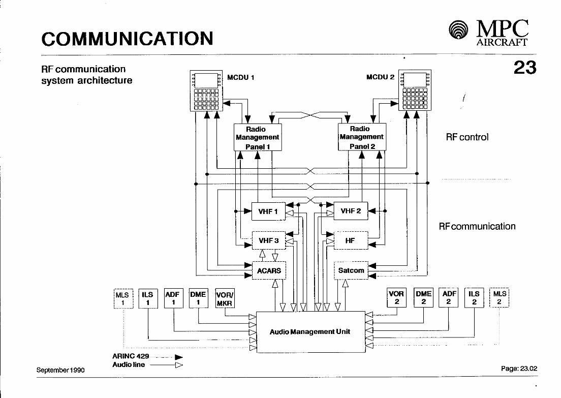
1 - RF communication: 23Main components are two VHF tranceivers and two Radio Management Panels (RMP). A third VHF transceiverand an HF transceiver are options, just äs the Aircraft Communication Addressing and Reporting System (ACARS)and a Satcom System. The ACARS uses only the third VHF.The Radios will be tuned via the two RMPs. Also tuning through the Flight Management System (CDU) ispossible.Bussystem is to the Standard ARINC 429 norm.
2 - Audio communication
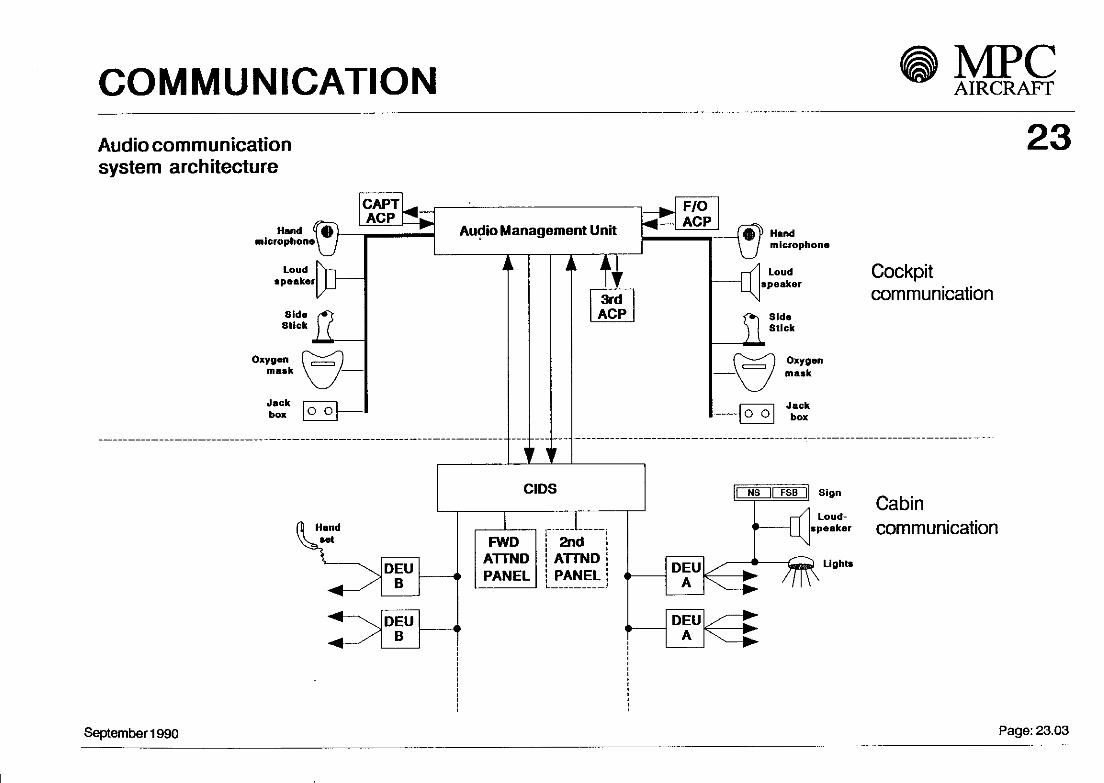
The audio management unit handles all audiosignals.The System is controlld by three Audio ControlPanels (ACP), where transceiver selection, volume control and other functions are possible. The Signalsfrom all microphones (except Cockpit Voice Recorder microphone) and from other sources are collectedin the Audio Management Unit and distributed to loudspeakers or, for cabin communication, to CIDS.
3 - Cabin communication
The cabin communication mainly is done through a Cabin Integrated Data System (CIDS). The signels aretransceived in a digitizform ed in a databus System between the Decoder/Encoder Units (DEU) and theCIDS director located in the avionic bay. The CIDS director also interfaces with the audio management unitsfor interphone functions.The System is controlled via the attendant panel. A second attendant panel is available äs an Option.
September 1990 Page: 23.01
COMMUNICATION MPCAIRCRAFT
RF communicationSystem architecture
MLS1
September 1990
ARINC 429Audio line
23
ADF1
DME1
VOR/MKR
LLt>t>t>-oo
OAudio Management Unit
RF control
RFcommunication
1
VOR2
1
DME2
1
ADF2
MLS2
Page: 23.02
COMMUNICATION MPCAIRCRAFT
Audio communicationSystem architecture
23
Handmicrophone^
LoudSpeaker
SideStick
Oxyganm äs k
Jackbox
CAPTAGP
Audio Management Unit
"
F/0ACP
rf
Handmicrophone
LoudSpeaker
SideStick
Oxygenmask
Cockpitcommunication
^ ^ JackO O box
Hand
DEUB
DEUB
— ( i
CIDS
...... . l __.FWD
ATTNDPANEL
2ndATTNDPANEL <
L J
i
1
>
NS || F S B ] | Sign
Loud-speaker
Cabincommunication
Lighta
September 1990 Page: 23.03

COMMUNICATION MPCAIRCRAFT
Antenna location MPC 75-10023
LOC #MLS t #TCAS VHF i # GPS 1/2 3 *SATCOM # HF VOR 1/2
0 0 0 0 0 0 0 0 0 0 0 0 0 0 0 0 0 0 0 0
* SPACEPROVISION
wx
# STRUCTURALPROVISION
GS # MLS 2 DME 1/2 # TCAS ATC 1/2 VHF 2 * OMEGA * FL. PHONE MKR RALT l RALT 2
September 1990 Page: 23.04/1

ELECTRICAL POWER MPCAIRCRAFT
24
Contents
1 - General
2 - Normal flight configuration
3 - Abnormal flight configuration
4 - Aircraft ground supply
5 - Electrical power generation control
September 1990
ELECTRICAL POWER AIRCRAFT
1. General: 24The electrical generation network consists of the following units:
AC Generation:
2 main integrated drive generators (IDG), one per engine, nominal 60 kVA. The IDG provides a 115 / 200 V,400 Hz AC supply. It consists of an oil spray cooled three states AC generator driven at constant speedby a hydromechanical constant speed drive.1 APU generator, nominal 60 kVA, to provide a seif contained source of ground power.This generator may also be used in flight to compensate the loss of main generators.1 ground power connector, nominal 60 kVA.1 emergency hydraulic driven generator (CSM/G), nominal 5 kVA.1 static inverter, nominal 350 VA, single phase 115V/ 400 Hz to provide a source of AC power from the batteries.
DC Generation:
3 transformer rectifier units (TRU), nominal 100 A at 28 V DC. Two of them are used to feed a DC maindistribution System. A third TRU supplies via the AC essential power the DC essential network.2 NiCd - batteries, nominal capacity 40 Ah each, provided for autonomous power for APU starting,DC equipment during transient switching of electrical power.
September 1990 Page: 24.01
J

ELECTRICAL POWER
2. Normal flight configuration: 24
In normal flight condition each IDG supplies an AG distribution network via generatorline contactors (GLC). These two networks are not parallel / isolated mode.
Under normal conditions:Distribution network No. 1 comprises:
- AC MAIN BUS 1- AC ESS BUS , which is supplied by AC MAIN BUS 1- GALLEY BUS 1-DC MAIN BUS 1 viaaTRU
Distribution network No. 2 comprises:- AC MAIN BUS 2- GALLEY BUS 2-DC MAIN BUS2viaaTRU
Two 40 Ah batteries are connected to the DC EMERGENCY BUS.
Each battery has its own busbar (BAT BUS 1 and BAT BUS 2) which are permanently connected.
September 1990 page. 24.02

ELECTRICAL POWER
3. Abnormal flight configuration: 24
Any one of the three generators is able to supply the total technical load and part of the commercialload. In case of total loss of all main AC power generation a hydraulic driven emergency generator( CSM/G ) with 5 kVA provides power for no limitation on usable time . ( CSM/G driven by the greenhydraulic circuit / engine driven pump or RAT ).
4. Aircraft ground supply:
On ground the complete network can be supplied either from the APU generator or fromthe ground power unit ( EXT - PWR ) up to a maximum of 60 kVAFor ground servicing Operation, it is possible to supply only the GND SERV AC / DC BUSdirectfrom the EXT - PWR connection.
5. Electrical power generation controls:
The electrical power generation and distribution control, indication and monitoringis operated through the Electronic Centralized Aircraft Monitoring System (ECAM) andthe overhead control panel.
September 1990 Page: 24.03

ELECTRICAL POWER MPCAIRCRAFT
System Architecture
i L
HYDR. =i CSM/G
< FUEL PUMPS)
AG MAIN BUSl
ELGALLEY BUS 1
AG ESS BUS
Tr1AC SHED ESS BUS
AC EMERG BUS
AC GND SERV BUS
GALLEY BUS 2Ur
AC MAIN BUS 2
TRU1
TRU2
24
DC MAIN BUS 1
DC SHED ESS BUSlr
DC ESS BUS
BAT BUS 1Lr
.BAT.1
HI-
DC EMERG BUS
rBAT BUS 2
.BAT.2
HI-DC GND SERV BUS
DC MAIN BUS 2
September 1990 Page: 24.04

Electrical Power MPCAIRCRAFT
Overhead-Panel
GCU1GEN1
September 1990
Emerg.Panel
ControlPanel
CMCMANAGEMENT
24System ManagementUttofabbravfation
CMC ConlraHzedMainleruuK« ComputerCSH/OCU ConMamSpMdMotor/GwieratorControlUnItECAM B«*onfc<^rrtraUzedAlrcnft MonitorOCU Generator Control UnitOPCU Qround Power Control UnitMCOU MuWpurpoMControl and Display Unlt
••M > Dtocroto Signal
AfllNC429databus
ECAM(Status Indication)
GCU2GEN2
GCU3APU
CSM/G CU
Page: 24.05

EQUIPMENT/FURNISHING MPCAIRCRAFT
Contents
1 - General
2 - Cockpit
3 - Cabin
4 - Underfloor cargo holds
25
September 1990 Page: 25.01

EQUIPMENT/FURNISHING
1. General
The MPC75 interior equipment/furnishings have been designed to provide a comfortable environmentfor the flight crew and passengers.This has been achieved by giving special attention to three main areas äs
- passenger comfort and cabin Styling
- carry-on baggage capacity
- underfloor compartment capability.
The major parts are provided within the pressurized section of the fuselage, äs follows:
- cockpit
- cabin
- underfloor cargo holds
25
September 1990 Page: 25.02

EQUIPMENT/FURNISHING
2. Cockpit 25The cockpit has been designed for two-man Operation with facilities for a third occupant.The flight compartment arrangement is shown in Fig. 25-1.The captain and first officer seats are seat rail mounted and fuliy adjustable in all directions.Each seat is fitted with an inertia-type five-point harness that allows a pilot to reach allaircraft controls without discomfort.
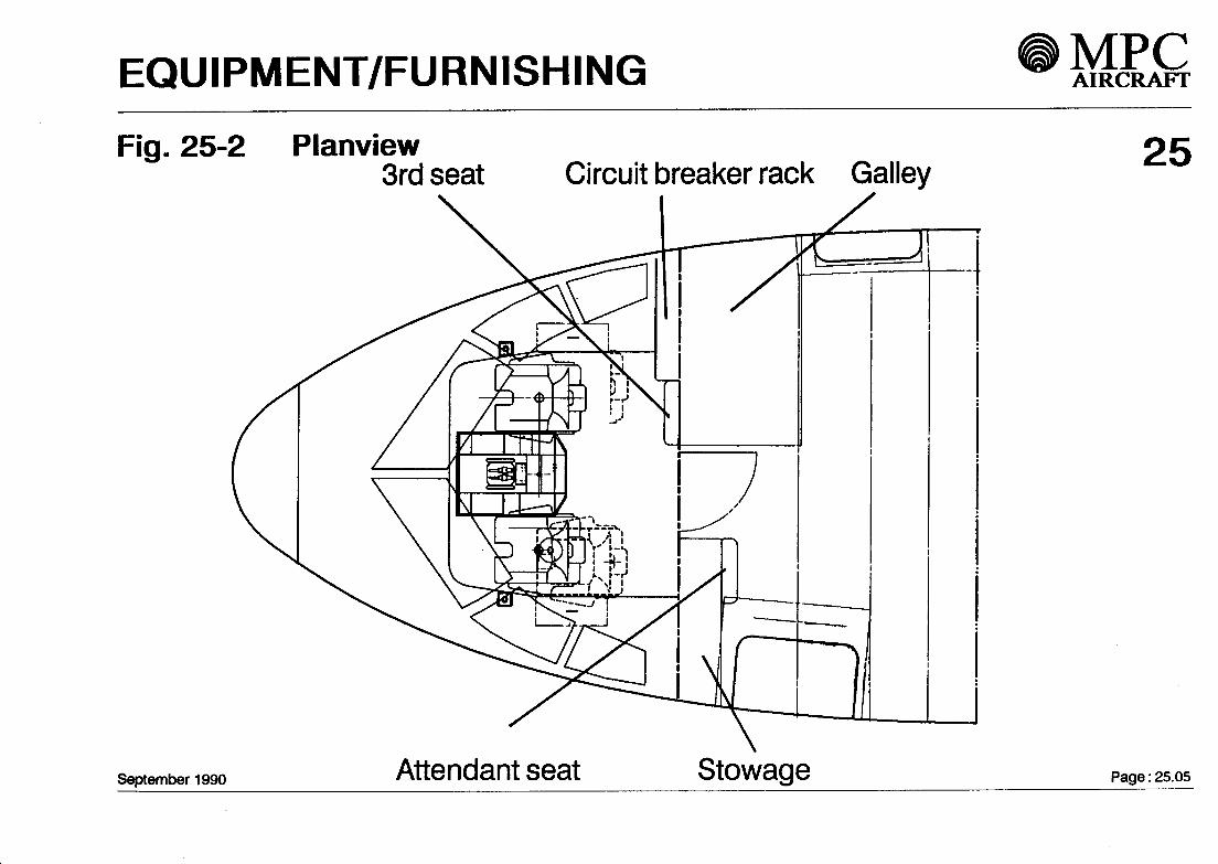
An observer seat is provided which occupies a position aft of the pedestal when in usebut is normally stowed against the right-hand aft wall of the flight compartment.The seat is provided with a fixed-type three-point harness.
The planview of the cockpit is shown in Fig. 25-2.For detail of the Instrument panels refer to chapter 31.
September 1990 Page: 25.03-1 /2

EQUIPMENT/FURNISHING
Cockpit Design 25
The main features:
- Sidestick Controllers leave the main Instrument panel unobstructed
- EFIS/ECAM/FWS Integration- Improved f lexibility through switching of six Fiat Panel Display Units- Standby Instrument display with similar Images
Most features evolved directly from A 320 such äs:
- "Lights out" philosophy on overhead panels
- "Need to know" concept for Information presentation- Monitoring of Systems through the ECAM-system
- Monitoring of Computers through Centralized Maintenance System (CMS, CFDS in A 320)
i
All control panels are within easy reach of the two crew members
A 3rd crew member seat aft of the pedestal offers maximum visibility over all panels
September 1 990 Page : 25.03-2/2

EQUIPMENT/FURNISHING MPCAIRCRAFT
Fig. 25-1 Forward view
September 1990
25
Page: 25.04
EQUIPMENT/FURNISHING MPCAIRCRAFT
Fig. 25-2 Planview3rd seat Circuit breaker rack Galley
September 1990 Attendant seat Stowage
25
Page: 25.05

EQUIPMENT/FURNISHING
3. Cabin 25The aim in the design of the Standard cabin has been to offer a higher Standard of comfortrelative to existing single-aisle aircraft in that class.This target, combined with the requirement to carry Iower and upper deck cargo either in bulkform or in Containers, results in the choice of a blended-double bubble fuselage cross-section havinga width of 3.45 m (1 35.8 in) and a height of 3.67 m (1 44.5 in).
The passenger cabin itself has a maximum width of 3.23 m (1 27 in) and a height of 2.1 0 m (82. in).
The MPC75 cabin interior has been designed according to the latest industrial design conceptswhich makes the cabin particularly spacious.All functional and decorative items such äs Windows, side-walls and ceiling panels and overheadstowage compartments have been longitudinally divided into two frame pitch (40 in) units. The factthat the cabin is parallel over most of its length and with a constant frame pitch, except around thewing box area, results in a minimum number of different furnishing panels.
September 1990 Page: 25.06
EQUIPMENT/FURNISHING AIRCRAFT
Standard Seat Layout 25
In its baseline configuration, the MPC75 provides single-class accommodation for 91 passengersat 32" pitch in a single-aisle, five-abreast, arrangement (see Fig. 25-3).
Other interior configurations are available for enhanced cabin flexibility.
The four seat rails running the length of the cabin allow 4 or 5 abreast seating (see Fig. 25-4).Standard and optional toilet and galley positions are provided at each end of the cabin either sideof the entrance areas (see Fig. 25-6 and Fig. 25-7).
The seat rails are spaced apart so äs to give approximately equal space under each seat, in5 abreast seating, for carry-on baggage (see Fig. 25-5).
Fixed galleys and lavatories are attached to the aircraft structure by bolts at hard points.
Lavatories are manufactured äs preassembled wet cells with an integrated floor panel designedäs a bowl for leakage protection.
September 1990 Page: 25.07

EQUIPMENT/FURNISHING MPCAIRCRAFT
Fig. 25-3 Standard seat layout 25
Baseline seat layout: 91 seats 32" pitch
A: Attendant seatG: GalleyL : LavatoryS: StowageW: Wardrobe
September 1990 Page: 25.08

EQUIPMENT/FURNISHING MPCAIRCRAFT
Fig. 25-4 Alternative seat layouts
Economy seat layout: 89seats 32"pitch
25
A: Anendant seatG: GalleyL : LavatoryS: StowageW: Wardrobe
September1990
Mixed class layout: 8 seats 36" pitch74 seats 32" pitch
Page: 25.09

EQUIPMENT/FURNISHING * MBQ
Cabin cross-section 25
Each seat is fitted with a two-point seat belt and gives a high degree of comfort with the followingfeatures:
- Lightweight aluminium structure- Reclineable back- Füll width table- Ashtray built into the armrest- Seat back pocket- Stowage for lifevest.
Passenger Service and information panels are provided above each seat row and are designed andinstalled with special consideration for passenger convenience.The panels are fully adjustable to match variations in seat pitch where optional cabin layouts arechosen. The features provided on each panel are:
- Readinglight- Individual air outlets- Attendant call buttons- Fasten seat belt/no smoking sign- Loudspeakers- Emergency oxygen.
September 1990 Page: 25.10

EQUIPMENT/FURNISHING MPCAIRCRAFT
Fig. 25-5 Cross-section
5 - abreast arrangement
all-economy class
63 " - 20 " - 42"
4 - abreast arrangement
first-class
50" - 23 " - 50"
September 1990 Page: 25.11

EQUIPMENT/FURNISHING MPCAIRCRAFT
Fig. 25-6 Location of galleys
The Standard aircraft is equipped with one galley in the forward cabin (G1).
Standard options are located in the forward cabin (G2) and in the aft cabin (G3, G4.).
25
September 1990
Standard - G1Option - G2, 63, G4
Page: 25.12

EQUIPMENT/FURNISHING MPCAIRCRAFT
Fig. 25-7 Location of lavatories
The Standard aircraft is equipped with two lavatories, both in the aft cabin.
Standard options are located in the forward and rear cabin areas.
25
Standard - E,FOption - A,C
September 1990 Page: 25.13

EQUIPMENT/FURNISHING MPCAIRCRAFT
Fig. 25-8 Location of cabin attendant seats
The Standard aircraft is equipped with two cabin attendant seats, one forward cabin (A1) and onein the aft cabin (A2).
Standard options are located in the aft cabin areas (A3.A4).
25
Standard - A1, A2Option - A3, A4
September 1990 Page: 25.14

EQUIPMENT/FURNISHING MPCAIRCRAFT
Overhead stowage compartments 25
For passengers' carry-on luggage the cabin is equipped with lateral overhead stowage compartments runningalong each side of the cabin above the passenger seating area. Each compartment is approximately 80"(2032 mm) and can carry a load of TBD Ib (TBD kg).
In the Standard all-economy seat layout with 91 passengers the total stowage volume is approximately 184 cu.ft.(5.2 m3). Thus there ist approximately 2 cu. ft. and TBD Ib (TBD kg) per seat.
A handrail is incorporated into each stowage compartment.
The optional overhead stowage bin has in the Standard all-economy seat layout with 91 passengers a total stowagevolume of approximately 217 cu. ft. (6.14 m3). Thus there is approximately 2.4 cu.ft. and TBD Ib (TBD kg) per seat.
Fig. 25-9 Standard bins Fig. 25-10 Optional bin
September 1990 Page: 25.15

EQUIPMENT/FURNISHING
Emergency equipment provisions 25The MPC 75 meets the JAR/FAR safety requirements for passenger emergency evacuation.The speed of evacuation is enhanced by:
- 20" wide aisle- 72" (H) x 34" (W) door fwd. left side and 55" (H) x 30" (W) door fwd. right side- 72" (H) x 30" (W) door aft left side and 55" (H) x 30" (W) door aft right side
The main doors are fitted with single lane slides. All slides are of inflatable type using cylinder compressed air.Escape slide illumination is achieved with lights integrated into the slides and powered from the aircraft emergencylighting System.
As an option, all passenger/service doors can be equipped with slide rafts instead of escape slides, which arefurnished with survival kits. The slide rafts can be disconnected from an inoperative door, moved to anotherdoor and mounted to the structural slide raft fittings.
In easily accessible positions in the passenger compartment, the following safety equipment is installed:- fire extinguishers,- protective breathing equipment,- portable oxygen units,- flashlights,- crash axe,- life vests,- megaphone,- first aid kits, etc.
September 1990 Page: 25.16

EQUIPMENT/FURNISHING MPCAIRCRAFT
Fig. 25-11 Escape slide arrangementType C door
30"x55"exitwithsingle lane slide orslide-raft.
Type C door
34"x72"exitwithsingie lane slide orslide-raft.September 1990
25Type C door
30"x55"exitwithsingle lane slide orslide-raft.
Type C door
3o"x72"exitwithsingle lane slide orslide-raft.
Page: 25.17

EQUIPMENT/FURNISHING
4. Underfloor cargo holds 25The forward and aft cargo holds are designed for bulk loading and to meet the requirements of"class D" regulations. Smoke warning System is available äs an Option, äs well äs a cargoVentilation System.
The basic doors are outward opening.
A semi automatic "sliding carpet" cargo loading System is available äs an Option.
September 1990 Page: 25.18

EQUIPMENT/FURNISHING MPCAIRCRAFT
Fig. 25-11 Location of cargo hold compartments 25
0 0 0 0 0 0 0 0 0 0 0 0 0 0 0 0 0 0 0 0 0 0 0 0 0 0 0 0
rrn
September 1990 Page: 25.19

FIRE PROTECTION MPCAIRCRAFT
Contents
2
3
4
5
6
General
Fire Protection Engines and APU
Smoke Detection Electronic Bay
Cargo Hold Smoke Detection
Portable Fire Extinguishers
Lavatory Fire Protection
26
September 1990 Page 26.01

FIRE PROTECTION
1. General 26Aircraft fire and smoke protection Systems are provided for:
- Engine and APU, fire detection and extinguishing Systems- Electronic bay smoke detection System- Automatic waste bin fire extinguishing System and smoke detectors in lavatories
Portable fire extinguishers are installed in the flight deck and the passenger cabin.
2. Fire Protection Engines and APU
2.1 DetectionThe detection loops for the engines and the APU are of pneumatic type. All detection loops are duplicated(Loops A and B). The Fire Source Detection Units (FSDU 1/2) 'acts' äs the 'central manager' between theSystems and the EIS äs well äs the overhead panel control and indication devices.
September1990 Page 26.02

FIRE PROTECTION
2.2 Extinguishing
The extinguishing System for each engine consists of two extinguisher bottles (APU one bottle), instaliedin the pylon area (engines). The APU extinguishing bottle Installation is close to the APU compartment.The bottles can be discharged by means of wired cärtridges.The APU fire extinguishing System is provided with an automatic sequence for fire extinguishing in anemergency case on ground if qualified personnel is not present in the cockpit.Extinguishing agent: HALON 1 301
3. Smpke Detection Electronic BaySmoke in the electronic bay is detected by Ionisation type smoke detectors, instalied in the air extractionduct. The smoke detector is connected to the FSDU and warnings are given on the Smoke Detection Panel(Overhead Panel) and associated Information will appear on the EIS.
4. Cargo Hold Smoke DetectionCan be provided äs an Option.
September1990 Page 26.03

FIRE PROTECTION • MEG
5. Portable Fire Extinguishers
Portable fire extinguishers are instalied at appropriate location in the flight and passenger compartment.Extinguishing agentwill be HALON 1211.
6. Lavatory Fire Protection
A smoke detector is instalied in the air extraction duct from each lavatory. The detectors are connectedto the FSDU. Audio and visual warnings of lavatory smoke are provided in flight compartment and at theattendants panel.Fire extinguishers will discharge automatically.
September 1990 Page 26.04

FIRE PROTECTION MPCAIRCRAFT
(OPTION)
ENGINE 1FIRE/OVERHEAT
DETECTION
ENGINE 2FIRE/OVERHEAT
DETECTION
APUFIRE/OVERHEAT
DETECTION
E.E.BAYSMOKEDETECTION
LAVATORYSMOKEDETECTION
CARGO HOLDSMOKEDETECTION
26
FIRE SOURCE DETECTION UNIT
(FSDU1)
l i iDISCRETE FIRE SIGNALS FIRE SOURCE DETECTION UNIT
( FSDU 2)
7\G
SYSTEM
CENTR.MAINTENANCESYSTEM
OVERHEAD PANELFIRE CONTROL PANELENGINE 1 APU ENGINE Z
FIREEXTINGUISHINGCONT.MONITORING
PRESSURE/SQUIBS
ENGINESAPU
CABINSMOKEWARNINGFACILITIES
September 1990 FIG. 26-00 Fire Protection Page 26.05

FLIGHT CONTROLS MPCAIRCRAFT
27
Contents
*
General
Architecture
Flight control and guidance Computers
Computer volume comparison
September 1990
L

FLIGHT CONTROLS
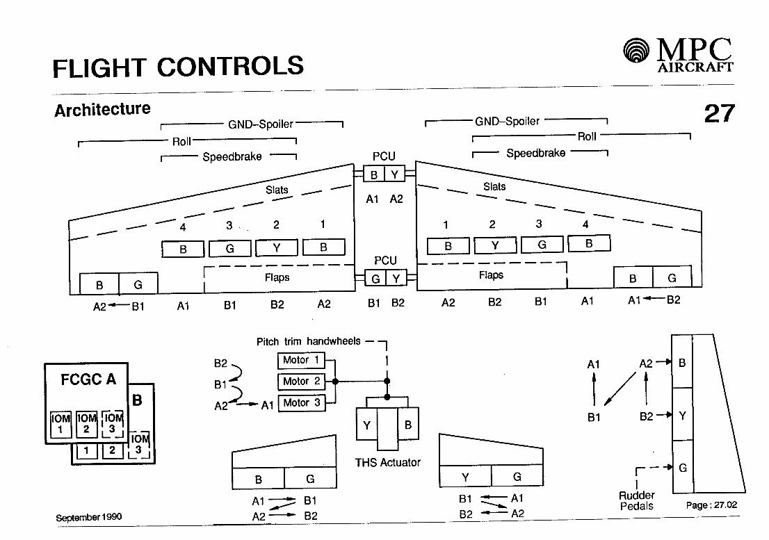
General 27M PC flight control is achieved by conventional surfaces which are f ully powered by hydraulic actuators. The flightcontrol System is designed äs a Fly-By-Wire (FBW) System based on two different types of digital Computers.
The aircraft' s primary flight control Systems - ailerons, roll spoilers, elevators, Trimmable Horizontal Stabilizer(THS) and rudder - control pitch, yaw, and roll flight attitudes. The secondary System comprises leading edgeslats and trailing edge flaps for high lift configuration, speed brakes for deceleration, and lift dumpers to improvebraking efficiency.
Some setected features of MPC flight control are:
• 3-axes FBW in pitch, roll, and yaw.
• Mechanical linkage to one rudder actuator and the THS
• Modern cockpit design with side stick Controller.
• Modern control laws for improved handling and safety.• Aircraft dispatchable after any single electrical flight control Computer failure or any single failure affecting
aileron, Spoiler or THS control.• No operational reduction after a single hydraulic failure in flight.
• Easy Identification of System failures with ECAM / Flight Warning System• High concentration of Computer tasks in each Computer module reduces EFCS-complexity. Flight control
Computer capacity can be reconfigured.
September 1 990 Pa9e : 27-01
FLIGHT CONTROLS MPCAIRCRAFT
Architecture
B
A2-—B1
GND-Spoiler
Roll"Speedbrake PCU
B B
r Flaps
A1 A2
PCU
A1 B1 B2 A2 B1 B2
•GND-Spoiler
•RollSpeedbrake
Flaps~I
A2 B2 B1 A1
27
B
B2
FCGCA
IOM1
l
IOM2
1
l 3 l
N
B
KflL_d_l
September 1990
Pitch trim handwheels —
B2
B1
A2
;>A1
Motor 1
Motor 2
Motor 3 i
B G
B
A1
B1
THS ActuatorG
A1A2
B1B2
B1B2
A1A2
A2
B2
r
B
G
RudderPedals Page: 27.02

FLIGHT CONTROLS MPCAIRCRAFT
Sidestick positionsRudder pedals positionPitch trim controlRudder trim controlSpeedbrake control lever positionSlat / flap control lever position
Air data moduls 1,2,3AHRS 1,2,3RA 1,2LGCIU 1,2Wheelspeed tachometersHydraulic pressure sensorsAccelerometersYaw rate gyrosEIUFCUFMCAutopilot sensors (ILS/VOR/DME ...)•Thrust lever position
Rudder pedalsPitch trim handwheels
ünks_
Flight ControlGuidance Computers
27. Nosewheel steering,
Auto brake. Warnings, Indications,
Maintenance, Recording
Elevators
Ailerons
r Rudder
rTrimmable Horizontal
Stabilizer
l| Tl ll L
Spoiler
l lJ l
l
Flaps/Slats
September 1990 Page: 27.02a
FLIGHT CONTROLS MPCAIRCRAFT
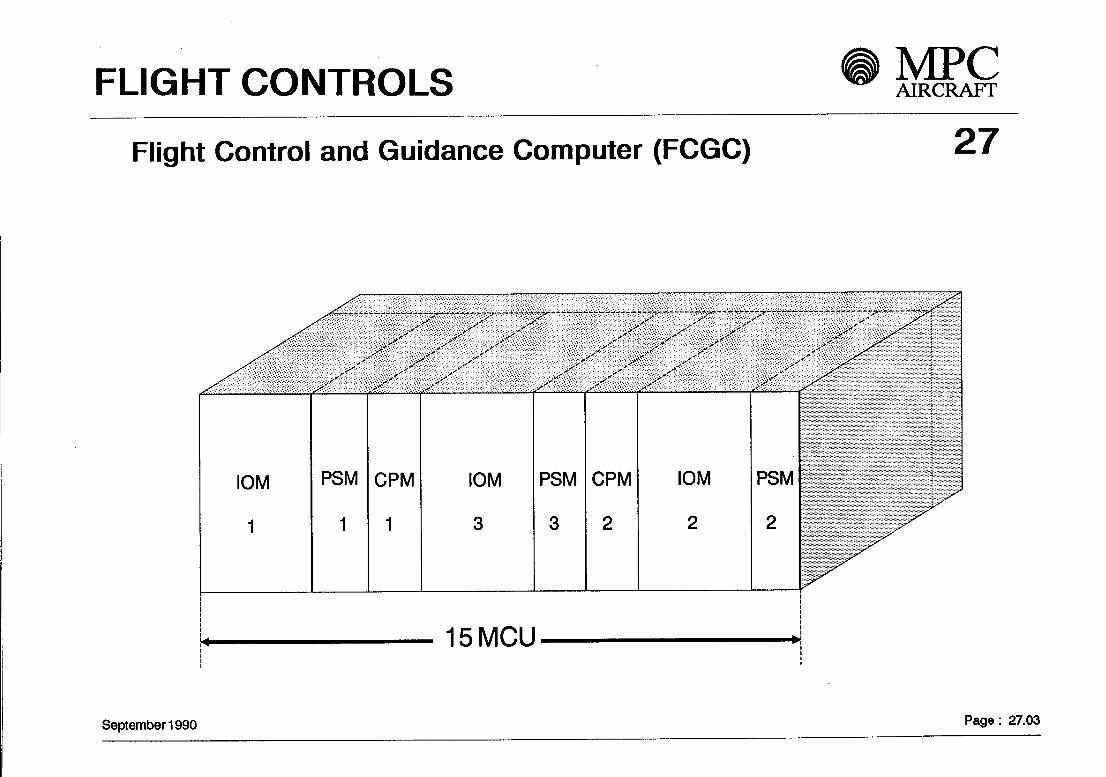
Flight Control and Guidance Computer (FCGC) 27
IOM
1
PSM
1
CPM
1
IOM
3
PSM
3
CPM
2
IOM
2
PSM
2
15MCU
September 1990 Page: 27.03

FLIGHT CONTROLS MPCAIRCRAFT
Flight control and guidance Computers
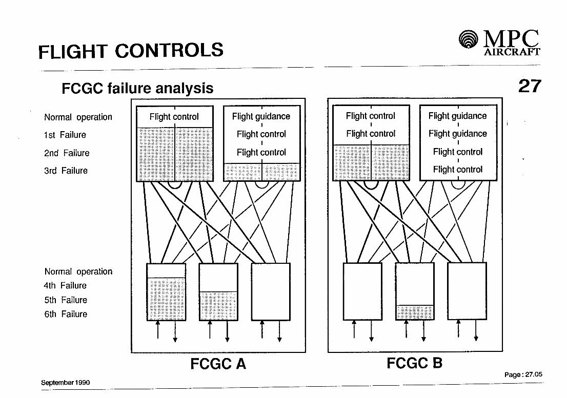
Flight control, envelope protectionand flight guidance cpmbutation isachieved by two dissimilarComputer Systems: FCGC A andFCGCB.
• Each FCGC comprises twoComputer Modules (CPM)each of them similar in hardwarebut dissiuiilar in Software, and threel/O-Modules (IOM) which connectthe FCGC to the pilot1 s controlsthe actuators, and the otheraircraft Systems and sensors.
Each CPM consists of twoComputing lanes which check eachother.
FCGC A
27
FCGCB
September 1990 Page: 27.04
FLIGHT CONTROLS MPCAIRCRAFT
FCGC failure analysis
Normal Operation
Ist Failure
2nd Failure
3rd Failure
Normal Operation
4th Failure
5th Failure
6th Failure
Flight control Flight guidance
Flight controli
Flight control
TTTIFCGC A
27Flight control
Flight control
Flight guidance
Flight guidancei
Flight control
T r TTFCGC B
September 1990Page: 27.05

FLIGHT CONTROLS MPCAIRCRAFT
Computer volume comparison
MCDU
FCU
32
Autoflight
ComputerVnli impMCU
FlightControl
September 1990 50
A320
2
1
FMGC-
2x8
FAC/V/Q«o
SFCC2x5
ELAC2x6
SEC3x8
FCDC2x2
27MPC75
2
1
12i FMC2
6FMC1
6
FCGCA/B2x15
30
Page : 27.06
FLIGHT CONTROLS
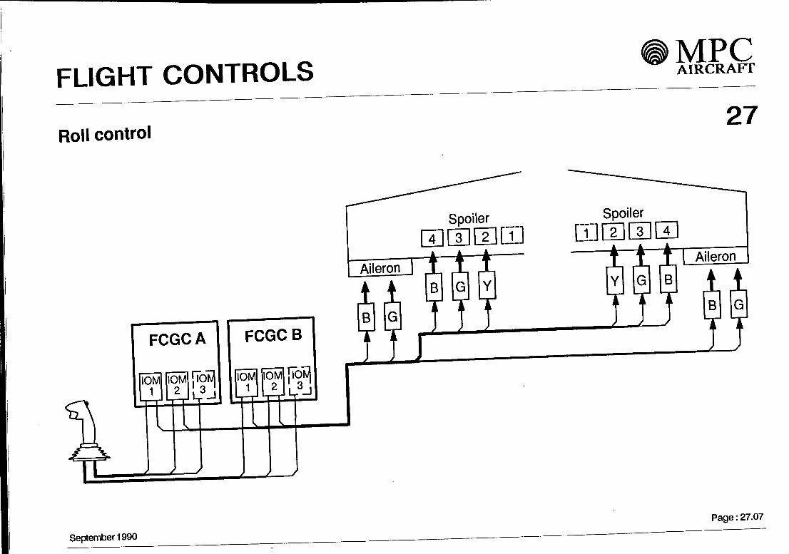
Roll control
MPCAIRCRAFT
27
FCGC A FCGC B
IOM| IOM ! lOtol IOM| IlOM ! ION/I1 1 o ' t ' 1 l l 9 *}1 2 1 J 1 ' 1 L _J— > h—rl l-r-rl LT — 1 L,— pl L,— rl h- — '
S\r ffAII f S S
Spoiler
Aileron
1B
t
G
1
4 3A A
t tB G
) )
2 LUt -
Y
t
Spoiler
[J] 2A
iY
J
3A
t
G
)
4
/B
)
Aileron
t tB GA i
) )
September 1990 Page: 27.07
FLIGHT CONTROLS MPCAIRCRAFT
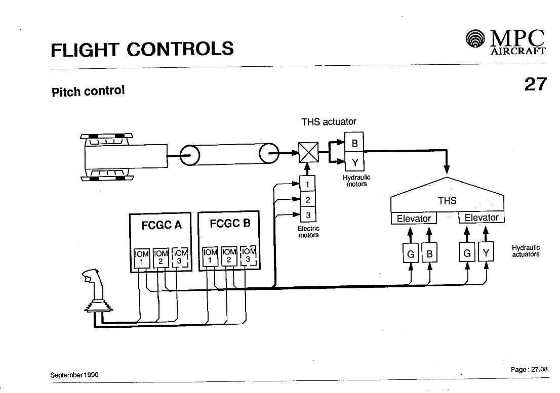
Pitch control 27
FCGCA
IOM IOM
f f_
I
FCGCB
[iöiüjl n \3_l
THS actuator
' S X
Electricmotors
Hydraulicmotors
THS
Elevator Elevator
fT TTHydraulicactuators
September 1990 Page: 27.08

FLIGHT CONTROLS MPCAIRCRAFT
Yaw control
Trim actuator Artificialfeel
C
27
September 1990 Page: 27.09

FLIGHT CONTROLS MPCAIRCRAFT
Ground spoiler control 27
SpeedBrakeLever
FCGCA
IOMI1
IOM2
L,-!
FCGCB
IOM1
X X
IOM2
X /
[iÖM|
Throttle
September 1990
Spoiler4 3 2 1
Weight On Wheels
Spoiler1 2 3 4
iiil IM lB
T T T T T T T T
Page: 27.10

FLIGHT CONTROLS
Speed brake control
MPCAIRCRAFT
27
Lever
Spoiler
a mm mt±l
Spoiler
["DOGGEttrt
FCGCj
IOM1
X
IOM |l<
2 !(
s X
A
DM!0 1AJ
FCGC
IOM1
IOM| !l<
2 1!
B
DM|
r
J J J J J T
September 1990 Page: 27.11
FLIGHT CONTROLS MPCAIRCRAFT
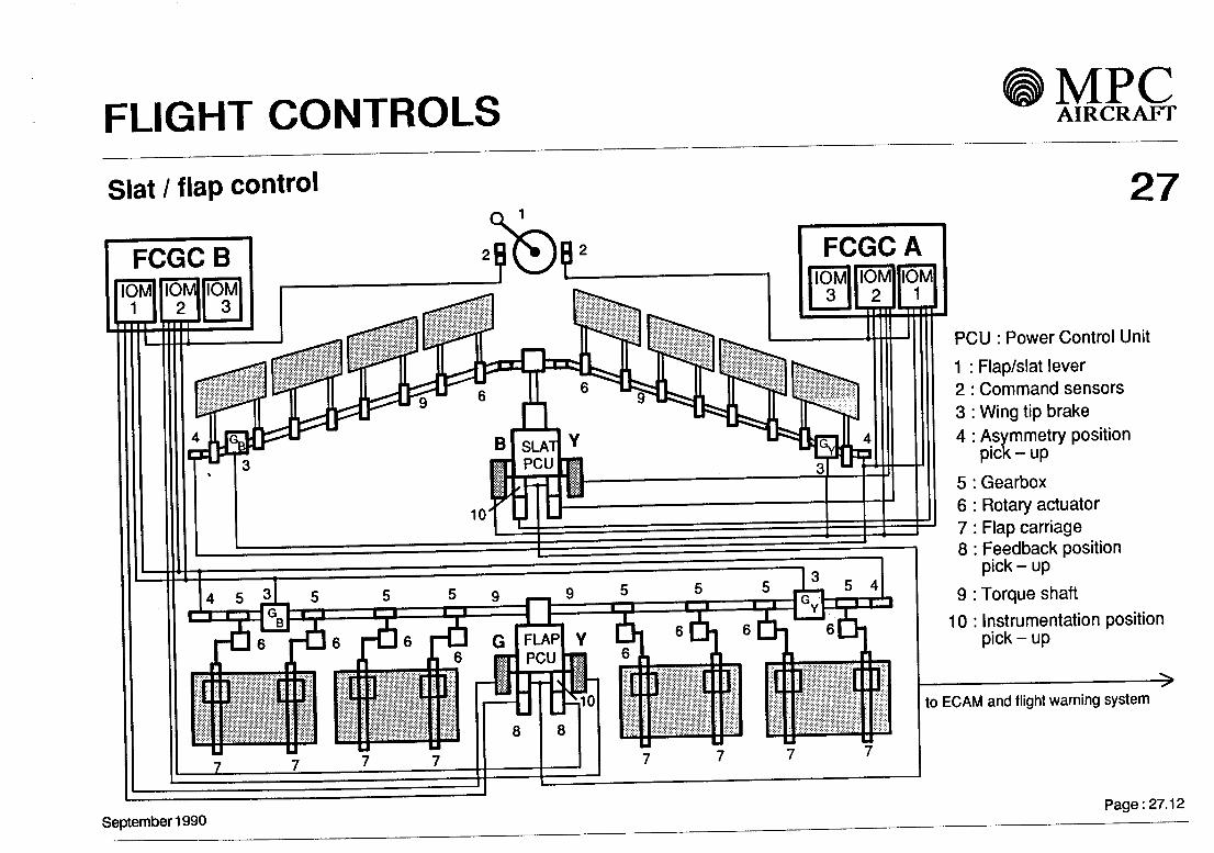
Slat / f lap control
FCGCB
27
PCU : Power Control Unit
1 : Flap/slat lever2: Command sensors3 : Wing tip brake4 : Asymmetry position
pick - up
5: Gearbox6 : Rotary actuator7: Flap carriage8: Feedback position
pick - up
9 : Torque shaft
10: Instrumentation positionpick - up
to ECAM and flight warning system
September 1990 Page: 27.12

FUEL MPCAIRCRAFT
28
Contents
1 - Storage
2 - Vent System
3 - Distribution
4 - Refuel / Defuel
5 - Quantity Indication
September 1990 Page 28.01

FUEL• VJE-L AIRCRAFT
281. Storage
Fuel is stored in two tanks, one in each outer wing spar box. The tanks are an integral part of the wing structure.2% expansion space is provided in each tank.The engines are fed from collector tanks between rib 1 and rib 2, which are protected by flapper valves.Water drain valves are installed at the Iowest points of each tank.A vent surge tank is located near each wing tip, which collects fuel spilled into the vent System.
Total wing fuel: 10,000 l (8,000 kg; density: 0.8 kg/l)
The centre wing box is free for a later capacity enlargement.
2. Vent System
Open vent System with non-icing NACA air inlet in outboard vent surge tank.Flame arrestors protects surge tanks against ground fire.Fuel spilled into the surge tanks is discharged back into the main tanks.
Optional centre tank vented via left hand vent surge tank.
September 1990 Page 28.02

AIRCRAFT
3. Distribution 28
Each engine is fed from two electrical bopster pumps (1 1 5 V AC 3-Ph.) located in the adjacent collector tank.Pumps are canister housed for removal without draining the tanks.One pump can supply one engine under all conditions.Pumps are controlled by pushbuttons on the overhead fuel control panel and monitored by pressure Switches,sensing at the outlet of each pump.Fuel shutoff valves with double electrical actuators are mounted at the front spars. The isolation of an engineis controlled by the engine master switch and the fire pushbutton.
A crossfeed valve with a double electrical actuator allows fuel supply from both tanks to one engine or fromone tank to both engines. The crossfeed valve is controlled by a pushbutton on the overhead fuel control panel.
Optional center tank with two pumps. Pumps identical to the wing tank pumps.
The APU is supplied from the LH supply System. On ground, a battery powered APU Starter pump can be used.The pump is canister housed. Pump control automatically by pressure switch.The APU fuel line is shrouded in pressurized areas of the fuselage and drained overboard.An APU shut-off valve with double actuator is mounted at the rear spar. Valve control is by the APU masterswitch and the APU fire pushbutton.
System control on overhead fuel control panel.System Status and failure indication on Electronic Instrument System (EIS) displays.
September 1990 Page 28.03

FUEL• UCL AIRCRAFT
4. Refuel / Defuel 28
Single pressure refuel coupling (2.5" Standard) under RH wing leading edge.Max. refuel rate 1200 l/min with 50 psig nominal pressure at the coupling.Refuel valves are solenoid actuated with manual override. Refuel valves canister housed.No fuel remaining in refuel pipe due to air inlet valve.
Automatic refuel distribution by use of Fuel Quantity Measuring System.Independent refuel shut-off by 'High Level' sensors.Refuelling possible by using battery power only.
Refuel panel located in RH wing fairing. It contains refuel and defuel valve control Switches, fuel preselector,digital indicators for preselected fuel, total fuel and fuel in each tank and 'High level' indication lights.
Cockpit refuel panel optional, allows preselection of required fuel quantity.
Defuel valve electrically actuated, manually controlled from refuel panel.Defuelling and fuel transfer from one tank to another possible by using the booster pumps.
Gravity filling point provided for each wing tank.
September 1990 Page 28.04

FUEL• i-lt- L AIRCRAFT
5. Quantity Indication 28
Fuel Quantity Indication
Capacitance type measuring System with linear probes.Computation by dual channel Fuel Quantity Control Computer (FQCC).Densitometer in each wing tank.Individual connection of all probes with FQCC for BITE function.ARINC 429 connection to Refuel Panel and aircraft Systems.Digital indication of fuel quantity on EIS and Refuel PanelDigital indication of fuel temperature on EIS, one temperature sensor located in each wing tank.
Level Sensing
'Low level' warning and 'high level' refuel shut-off controlled by independent level sensing stage, integratedin FQCC. One 'Iow level' sensor and one 'high level' sensor in each tank.Independent power supply.Sensor BITE control via FQCC.
Secondary Fuel Quantity Indication
Magnetic Level Indicators (MLI) can be used on ground in connection with an attitude monitor andcorrection charts.
Provision for centre tank equipment similar to wing tanks (except temperature measurement).
September 1990 Page 28.05

FUEL MPCAIRCRAFT
Fuel System Schematic
/ ENG \8
FLOATVENTVALVE
September 1990
SINGLE POINTPRESS. REFUELING
SURGETANK
NACA FLUSHAIR INTAKE
Page 28.06
HYDRAULIC SYSTEM MPCAIRCRAFT
29
Contents
2
3
4
5
General
Hydraulic System description
Installation and distribution
Indication and control
Ground handling
October1990 Page 29.01

HYDRAULIC SYSTEM AIRCRAFT
1 - General
The hydraulic System powers the hydraulic actuation for the flight control System, the landing gearand the braking system. It consists of three fully independent hydraulic circuits, äs there is no manualmode for the flight control.
The system failures including dormant failures shall not prevent continued safe flight andlanding unless they are extremely improbable.
3000 psi supply pressure is delivered from piston pumps with variable displacements. All pumps areof conventional types.
The fire-resistant hydraulic fluid is of phosphate ester type.
29
October1990 Page: 29.02

HYDRAULIC SYSTEM
OQ2- Hydraulic System description ^^
Three independet hydraulic circuits - called No.1 / green System, No.2 / blue System and No.3 /yellowSystem are continuously operating and supply power to their respective sub Systems äs shown on thepage 29.08.
No. 1 System / green derives primary power from one engine driven pump ( EDP ) mounted on theleft engine . Additional power is provided by an electric driven pump .
No. 3 System / yellow is similar, except that the EDP is mounted on the right engine . The Systemincludes also an electric driven pump .
No. 2 system / blue is powered from a continuously operating electric driven pump .
Each hydraulic System has an air pressurized reservoir .
In case of double engine failure,emergency hydraulic power will be provided via a ram air turbine ( RAT )to the blue system .
October1990 Page: 29.03

HYDRAULIC SYSTEM ^ME£AIRCRAFT
29The primary flight control servos are protected against high flow consumers by priority valves .
High pressure filters are installed in each pump delivery line providing a continuous cleaningof the hydraulic fluid The return and the case drain lines are equipped with Iow pressure filters .
The high pressure lines of all hydraulic circuits are protected against overpressure by relief valves
3- Installation and distribution
In order to meet the segregation requirements the three hydraulic circuits are separated insuch a manner that at least one System remains undamaged at any one failure .This consideration includes all components and the pipe routing located in the areasexposed to damage i.e. due to engine desintegration, tyre burst or accumulator burst.
The hydraulic consumers are distributed to the three hydraulic circuits in away to provide a well balanced and efficient System with adequate redundancy .
October1990 Page: 29.04

HYDRAULIC SYSTEM AIRCRAFT
29Provision is made for the Installation of manifolds in each hydraulic circuit . These manifoldsinclude hydraulic components which help to minimize the number of pipes and unions andprovide easy maintenance.
Different materials for the pipes are considered :- Titanium alloy for all high pressure pipes .- Aluminium alloy , corrosion protected , for all Iow pressure pipes such äs return , suctionand drain pipes.
- Stainless steel for all high and Iow pressure pipes installed in the fire exposed areasand for coiled pipes.
October1990 Page: 29.05

HYDRAULIC SYSTEM AIRCRAFT
4- Indication and control 29
Indication is provided on the ECAM displays and on the overhead panel for the followingParameters:
- Reservoir Iow pressure level- Reservoir quantity- Reservoir Iow air pressure- High System pump pressure- Low System pressure- Fluid temperature
The two engine driven pumps, the electric driven pumps , the deployment of the RATand the EDP-depressurizing valves are controlled by push buttons .The fire shut-off valves are controlled by the engine fire handles .
October1990 Page: 29.06

HYDRAULIC SYSTEM AIRCRAFT
5- Ground handling 29
Reservoir refilling is provided by means of a hand-pump and refilling selector valve which allowsto select the reservoir to be refilled .
External ground connections for the electric and hydraulic power supply are available .
The three hydraulic reservoirs can be externally air pressurized by means of a separatecentralized connection.
October1990 Page: 29.07

HYDRAULIC SYSTEM MPCAIRCRAFT
MAINSYSTEM MAINACC SYSTEM
ACC
PRIORITYVALVE
29
October 1990 Page: 29.08

IGE AND RAIN PROTECTION MPCAIRCRAFT
30
Contents
2
3
4
5
6
7
8
General
Wing Anti Ice (WAI) System
Nacelle Anti Ice (NAI) System
Ice Detection System
Cockpit Windows
Probe Hearing
Waste Water Drain MastHeating
Rain Removal System
SEPTEMBER 1990 Page 30.01

ICE AND RAIN PROTECTION AIRCRAFT
1. General 30Critical areas of the aircraft are protected against ice by hot air Systems or electrical heating.The ice protection System permits unrestricted aircraft Operation in ice and rain conditions.
1.1 Hot Air Systems- The slats outboard the engines of each wing- The engine air intakes
1.2 Electrical Heating Systems- The fligr^t compartment Windows- The air data probes and sensors- The waste water drain mast
1.3 Rain Removal- The front windshields by wipers- Rain repellent fluid System (Option)
SEPTEMBER 1990 Page 30.02

IGE AND RAIN PROTECTION
2. Wing Anti Ice (WAI) System 30
2.1 DescriptionThe slats outboard the engines are protected by means of hot air. The air is taken from the pneumatic Systemand the supply to each wing is controlled by shut-off/pressure reducing valves. A flow limiter (orifice) is fitteddownstream of the valve.A telescope duct feeds the piccolo tube in the slats. The hot air passes through slots and exhausts via holesalong the slat rear skin and discharges through gaps between the slat trailing edge and the fixed wing.
2.2 System OperationThe System will be controlled automatically by the IGE DETECTION CONTROL LOGIC, which is connected to twoice detectors. In case of one ice detector failure indication on the EIS is shown and manual System controlis possible (Pushbuttons on the overhead panel).
3. Nacelle Anti Ice (NAI) SystemDescription:The engine nacelles are anti-iced by hot air. The control valve (ON/OFF) is operated automatically from theIce Detection Control Logic or manually by the use of the pushbuttons on the overhead panel.
SEPTEMBER 1990 Page 30.03

ICE AND RAIN PROTECTION • MEß-
4. Ice Detection System 30The ice detection System is a primary System with 'AUTO'-control for WAI and NAI. Therefore two ice detectorsare installed and connected to the Ice Detection Control Logic.In case of one ice detector failure Information will be given on the EIS and System Operation control forWAI and/or NAI is manually possible.
5. Cockpit WindowsThe windshields and side Windows are protected against fogging and icing by electrical heating whereasthe windshields are additionally demisted by conditioned air.Control and monitoring units on each side monitor, control and regulate the System. On each side temperaturecontrol of front and lateral Windows are independent.Engine starting automatically initiates the System functioning.
6. Probe HeatingAir data probes and sensors (TAT) are electrically heated.In order to allow correct Operation of the aircraft after a major electrical power supply failure, one System issupplied from the emergency electrical supply.
SEPTEMBER 1990 Page 30.04

IGE AND RAIN PROTECTION AIRCRAFT
307. Waste Water Drain Mast Heating
The lavatory/galley waste water drain masts are electrically heated to prevent ice formation. The heatinglevel is automatically reduced when the main landing gear is extended. Heating is operative äs long äspower is avaiiable.
8. Rain Removal SystemEach front windshield is equipped with a two speed electric wiper. A rain repeilent System can be instaliedoptionally.
SEPTEMBER 1990 Page 30.05

IGE AND RAIN PROTECTION MPCAIRCRAFT
Wing Anti Ice
ENGINEBLEEDAIR
ECS1
APUBLEEDAIR
Control Volve
Restrictor
'Crossfeed-valve
11
ECS2
Supplyduct
Telescopic DuctFlexible InterconnectionPiccolo Tube
30
SEPTEMBER 1990 Page 30.06

IGE AND RAIN PROTECTION MPCAIRCRAFT
Nacelle Anti Ice and Ice Detection 30
WINQ
Engine 1
Ice Detector 1
ANTI IGE
ENG.2
ICE DETECTION
CONTROL LOGIC
l
l
Electr.Power l
TOEIS
Antiiced area
Engine 2
Valve, ON/OFF
Valve position indicating
Ice detector Signal ICE
Hot Airsupply duct
Valve positioncontrol
/ce Detector 2
SEPTEMBER 1990 Page 30.07

INDICATING / RECORDING MPCAIRCRAFT
Contents
1 - Cockpit panels
2 - Electronic instrument System
3 - Standby instrument
4 - Recording
I
31

INDICATING AND RECORDING
31
1 - Cockpit panels
iSeptember 1990 Page: 31.01

INDICATING AND RECORDING MPCAIRCRAFT
Main Instrument panelMaster warning/caution l
Flight control unit
EFIS control panel
t~~Side panel
EFISdisplays-
September 1990
Standby
Instrument
panel
ECAM displays Landinggear
L—and brake
panel
31
STANDBYINSTRUMENTDISPLAY
Side panel •
EFISdisplays
Page: 31.02

INDICATING AND RECORDING MPCAIRCRAFT
Pedestal
In addition to the thrust levers and engine controlfunctions the main features are:
- Pitch trim wheels- Flap/slat control lever- Airbrake control lever- Rudder trim panel- Multipurpose Control and Display Units (MCDU)for flight management, maintenance.data link, etc.
- Radio Management Panels (RMP) for communica-tion and navigation control function
- Audio Control Panel (ACP) for intercommunication,transmitting/receiving function
- Lighting Control Panel- Gravity landing gear control handle for emergencyfunction
SEPTEMBER 1990
0000000000
l©©©00000©0000000©0000000O0OEBQ0S
öooöööoO-H3
O O O O OOfi @E
0>l «• X >l
O ü O.T
rl£Ki' »W'lf.^
PITCH TRIM KHEELS
B B B E3 B HB 0 B B B B(jg) El B g)
HBfaDCaq 00000
1000000©©EI0000©0000000©0000000O0O0EKD0B
5 v*rt «t t t* l t*t Ml CM
O O O O O O
$ m-g O~Q0006 öS
_EL
31
Page:31.03

INDICATING AND RECORDING MPCAIRCRAFT
Overhead panel
The overhead panel has a
three-row arrangement with
the main engine related
Systems in the centre line.
The Iower section is for
frequently used Systems,
where the upper section is
reserved to handle any ab-normal situations.
dTTö> q
D cn. «• tarn ot int
CALLB IM
C3•CMll
RAIN RPLNT W1PER
HENT l
BJiovn •
B
4^E fft±L fZtl
PROVISION CENTER TAMf
PROOE/WMXJWICAT
ATJB.T,
OH3M iu <m «n
oooo oo
t VENTILATICSfT
g U> PBtSS
WH v/t nv. um n. „ »
RAIN WLNl WIPtB
31
SEPTEMBER 1990 Page: 31.04

INDICATING AND RECORDING
EIS components
Six identical flat panel Display Units (DU)Size 7.25" x 7.25", füll colour, high resolutionIntegrated graphic generatorInternal source switching (DMP)
Three Display Management Processors (DMP)Digital High Speed (HS) data link to display unitsNo.3 DMP may replace either No.1 or No. 2
- Flight Warning processing integrated in the DMP'sFully redundant warning/caution generation
Two Warning Acquisition Concentrators (WAG)Fully redundant System data acquisition
2 - Electronic Instrument System (EIS) 31
September 1990 Page: 31.05

INDICATING AND RECORDING MPCAIRCRAFT
EIS general arrangement
EFIScontrol panel
NavigationDisplay
Primary FlightDisplay ~~
SEPTEMBER 1990ECAM Transfercontrol panel switching panel
31
EFIScontrol panel
NavigationDisplay
Primary FlightDisplay
Page:31.06

INDICATING AND RECORDING MPCAIRCRAFT
Electronic Instrument and Flight Warning System
j_
WXR
SEPTEMBER 1990
fEFIS l FCU EFIS 2l
31
ECAMCONTROLPANEL
WXR
Page:31.07
INDICATING AND RECORDING ® MIESAIRCRAFT
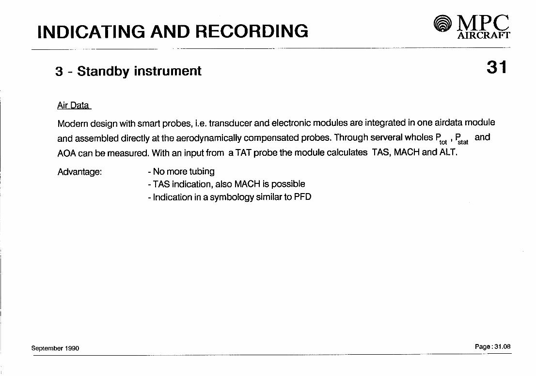
3 - Standby Instrument 31
Air Data
Modern design with smart probes, i.e. transducer and electronic modules are integrated in one airdata module
and assembled directly at the aerodynamically compensated probes. Through serveral wholes Ptot, Ptat and
AOA can be measured. With an input from a TAT probe the module calculates TAS, MACH and ALT.
Advantage: - No more tubing- TAS indication, also MACH is possible- Indication in a symbology similar to PFD
September 1990 Page: 31.08

INDICATING AND RECORDING MPCAIRCRAFT
StandbyLCD-Display
SEPTEMBER 1990
31
Page:31.09

rINDICATING AND RECORDING MPC
AIRCRAFT
Standby instruments
RADIAL LOC/GS BEARING
GCO
3S?
u.Q
31
MAGN.NORTH MAGN.NORTH TAS.MACHSTANGE ATTITÜDE ATTITÜDE ALTTTÜDE
W
z » » £ aUJ oc QC < 55 i i s iQ < < £ o
< 5
PROBEHEATER
SEPTEMBER 1990
BATTERY POWER BUS 24VDC
Page:31.10
INDICATING AND RECORDINGMPCAIRCRAFT
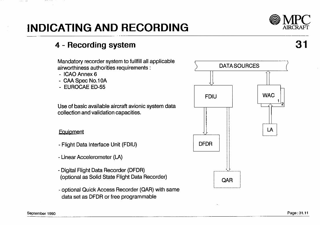
4 - Recording System 31Mandatory recorder System to fullfill all applicableairworthiness authorities requirements:- ICAOAnnexö- CAASpecNo.lOA- EUROCAEED-55
Use of basic available aircraft avionic System datacollection and validation capacities.
Equipment
- Flight Data Interface Unit (FDIU)
- Linear Accelerometer (LA)
- Digital Flight Data Recorder (DFDR)(optional äs Solid State Flight Data Recorder)
- optional Quick Access Recorder (QAR) with samedata set äs DFDR or free programmable
DATASOURCES
FDIU
\
QAR
September 1990 Page:31.11

LANDING GEAR MPCAIRCRAFT
32
Contents
General
Landing gear Operation
Braking System
Steering System
Landing gear arrangement
Main landing gear
Nose landing gear
September 1990

LANDING GEAR AIRCRAFT
General 32
The MPC 75 landing gear is of the conventional retractable tricycle type with direct action shock absorbers. The mainlanding gear is wingmounted and retracts sideways into the fuselage. The nose landing gear retracts forward into thefuselage.
All tires shall be of the radial type. The main gear tire size is H40x14-R19 and the nose gear tire size is 24x7.7-R10.Bias tires shall be also available in the same size äs an Option.
Landing gear Operation
The nose and main landing gears are operated by hydraulic actuating jacks. The landing gears are mechanically lockedin the fully extended and retracted positions.The sequence of the gears is electrically controlled by duplicated Systems incorporated in a Landing Gear Control andInterface Unit (LGCIU) which utilises proximity Switches to detect the various gear positions. An emergency extensionSystem shall be installed.There are conventional lighted annunciators on the centre Instrument panel and a second display on ECAM to providevisual monitoring of the gear Operation and position.
September 1990 Page: 32.01

LANDING GEAR
Braking System 32
The braking System incorporates four braking modes, besides an antiskid and an automatic braking System (autobrake). The main landing gears are equipped with carbon brakes. Steel brakes shall be optional available. The braketemperature is indicated on ECAM. Provisions are provided for Installation of optional brake cooling fans.
The normal braking mode is supplied by the green hydraulic System. The controi computation is done in a fully digitalBrake and Steering Controi Unit (BSCU) which Signals a servovalve for each wheel. For redundancy the BSCU hastwo identical channels with two separate electrical power supplies.
The alternate braking mode is supplied by the yellow hydraulic System. The pressure is controlled by a hydraulicmetering valve and antiskid function is provided through one alternate servovalve for each wheel (signalled by BSCU).The autobrake System is not available in this mode.
The alternate braking without antiskid mode is similar to the alternate mode with the exception that the antiskid functionis not available.
The parking brake mode is activated by an electrical switch. Switching on the parking brake deactivates all otherbraking modes. Hydraulic pressure is supplied from the yellow System or from the brake accumulator.
September 1990 Page: 32.02
LANDING GEAR MPCAIRCRAFT
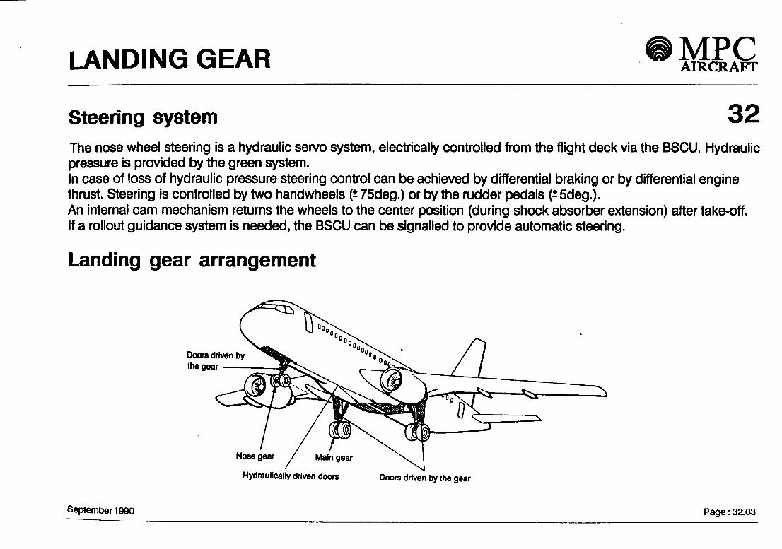
Steering System 32The nose wheel steering is a hydraulic servo System, electrically controlled from the flight deck via the BSCU. Hydraulicpressure is provided by the green System.In case of loss of hydraulic pressure steering control can be achieved by differential braking or by differential enginethrust. Steering is controlled by two handwheels (±75deg.) or by the rudder pedals (±5deg.).An infernal cam mechanism returns the wheels to the center position (during shock absorber extension) after take-off.If a rollout guidance System is needed, the BSCU can be signalled to provide automatic steering.
Landing gear arrangement
Doors driven bythe gear
Nose gear
Hydraulically driven doors Doors driven by the gear
September 1990 Page: 32.03

LANDING GEAR MPCAIRCRAFT
Main landing gear 32
VIEW X Pintle axis
Side sfay
fuüy extended
September 1990 Page: 32.04

LANDING GEAR MPCAIRCRAFT
Nose landing gear 32
Refracfion actuator
Steering aduator
\Torque links
Tire size 2^7.7-RW
Statte ground line
September 1990 Page: 32.05

LIGHTS MPCAIRCRAFT
33
Contents
1 - General
2- Cockpit
3- Cabin
4- Cargo and Service area
5- Exterior
6- Emergency lighting
September 1990

•••••• h l III i ^CH^ . TT"* /""1T"* A T~v-r<AIRCRAFT
l- General 33
- Sufficient illumination is provided to passengers, crew and ground Service.
- Lights System is designed to comply with requirements of JAR relevant items.
-White lighting is used for cockpit illumination. The cockpit lighting is designed to comply with the dark cockpitprinciple.
-The state-of-the-art technology is applied to lights System.
-The lights panel is located on the overhead panel in the cockpit.
2-Cockpit
-Two dorne lights with dimming control are installed to provide cockpit general illumination.
- Side consoles and its briefcase stowage and map holder lights are installed on each side console.
-Floor lights are located beside crew seats.
- Instrument and panel integral lighting with remote stepless dimming control are provided.
- Flood lights provide illumination for instrument panel and pedestal.
-Adjustable reading lights for the captain and first officer are installed in the ceiling. The pedestal floodlight isalso used for thethird occupant.
- Annunciator light dimming and test function are provided.
September 1990 Page: 33.01

LIGHTS MPCAIRCRAFT
Lights panel
FUXJO LT INTEO LT FUXD LT•MMPIt. »»m.«PlD
33
September 1990
EXT LTBTROBC BEACON HXNO NAV t LOGOON ON ON OH
TAXIoj
ON
M^RETRACf*
SIGNSSEAT KLTS K] 9WXIN9
ON ON
OMOWTOLTINT LT
Page: 33.02
LIGHTS ® MPCl—• ^ • • • ^^ A TT> rf-«r> A erAIRCRAFT
3-Cabin 33
- Four Strips of fluorescent tubes with dimming control are used for passenger compartment general Illumination.
- Two fluorescent tubes are installed in each entrance area ceiling.
- Call lights are prepared for passengers and crew.
- Fluorescent light is provided in each lavatory to illuminate the wash basin and mirror.
-A reading light is provided for every passenger seat onthePSUs.
- Lighted NO SMOKING, FASTEN SEAT BELT and EXIT signs are provided in the passenger cabin.A RETURN TO SEAT sign is provided in each lavatory. The TOILET OCCUPIED sign is located close tolavatories on the cabin visible wall.
- Special galley work lights form part of the fixed BFE galley equipment. The Illumination is provided at theattendant's seat.
- Passenger stairway lights are integrated in the stairway.
4-Cargo and Service area-A separate lighting System is installed in cargo hold. The lights are controlled by each cargo door.
- Loading area light is sufficient to permit reading of labels on the ground in front of the cargo door.
- Service lights and electrical outlets are provided in all Service bays.
September 1990 Page: 33.03

LIGHTS MPCAIRCRAFT
CABIN GENERAL FLUORESCENT LIGHTING
PASSENGERREADINGLIGHTS
PASSENGERREADINGLIGHTS
AISLE EMERGENCY LIGHTING
~7 ' ','',//'//'//////
33
September 1990 Page: 33.04

LIGHTS|_IV2I • • VJ AIRCRAFT
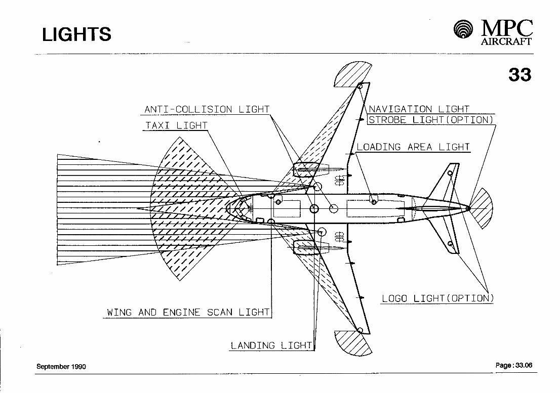
5-Exterior 33-Twoforward facing navigation Hghts are installed on both wing tips and a rearward facing navigation light is
installed in the tan cone.-Two retractable landing lights are installed on the fixed underwing panel.
-Two fixed taxi lights are installed on the nose landing gear to provide wide beam illumination for taxiing.
-Two anti-collision/strobe lights are installed on top and bottom of the fuselage along the centre line.
-Two wing and engine scan lights on each side of the fuselage are provided to illuminate the wing leading edgeand the engine intake.
- Logo lights are provided on both sides of the horizontal tail äs an Option to illuminate the airline's logo on bothsides of the vertical tail whenever the landing gear is extended.
-Strobe lights at wing tips and tail cone äs an Option are used äs a duplicated navigation lighting System.
6-Emergency lighting-Some of the cockpit lights are used for emergency lighting powered by essential busbars.
-Cabin emergency lights are provided to illuminate the aisle area.
- A dome light is provided in each lavatory powered from essential busbar.
- Evacuation path lights are installed in the stairway and slides.
- Floor proximity escape path marking consists of pathway lights and EXIT signs above floor.
-The Emergency Power Supply Units equipped with internal Ni/Cd batteries will provide sufficient power to allemergency lights and signs for at least 12 minutes.
September 1990 Page: 33.05
LIGHTS MPCAIRCRAFT
ANTI-COLLISION LIGHT
33
NAVIGATION LIGHTSTROBE LIGHT(OPTION)
LOADING AREA LIGHT
LOGO LIGHT(OPTION)WING AND ENGINE SCAN LIGHT
LANDING LIGHT
September 1990 Page: 33.06
NAVIGATION MPCAIRCRAFT
34
Contents
- General
- Radio navigation aids
- Air data / attitude / heading

NAVIGATION MPCAIRCRAFT
Air data and attitude SystemH WXR hf 1
-« .- r r n WARN «--, —i——*—3rdPitot.StaticAOA
TAS, ALTMach
CPT'sPitot.StaticAOA,TAS, ALTMach
TAT 1 =L
34
September 1990
f] F/O'S/ Pitot «Statics AOA,/ TAS, ALT
Mach
TAT 2
DATA BUSSESTO USER SYSTEMS
Page: 34.01

NAVIGATION ^ MEß
2 - Radio Navigation Aids 34
The aircraft is equipped with conventional navigation aids. They are automatic tuned through the Flight ManagementSystem (FMS), for DME, VOR and ADF, or manual via the Radio Management Panels (RMP).
ILS and MLS will be integrated in one LRU if ever MLS becomes operational.Global Positioning System( GPS) is a Standard Option, and will be integrated in the AHRS or IRS.The Traffic Collision Alert and Avoidance System (TCAS) is an optional Installation (for US operator mandantory1993)
3 - Air Data and Attitüde System
The aircraft offers a triple Installation of air data Systems and Attitüde and Heading Reference System (AHRS).All installed air data probes are smart probes, which are aerodynamically compensated. They supply theSystem with pitot, static and alpha air data. The data are converted to ARINC 429 format in the Air Data Modules(ADM) that are mounted directly to the probes. With an input of Total Air Temperature (TAT) the ADMscalculate the miscellaneous air data TAS, ALT and Mach.
Basically the aircraft is equipped with conventional strapdown AHRS updated by two manetic sense units.The installation of an optical gyro Inertial Reference System (IRS) is provided äs a Standard Option.Both sytems are of the same size (4 MCU) an can be upgraded by an optional GPS Integration.
September 1990 Page: 34.02

Navigation MPCAIRCRAFT
Radio Navigation
To DMPs
FCGC 1September 1990
FCGC 2Page: 34.03

OXYGEN SYSTEM MPCAIRCRAFT
35
Contents
1 - General
2 - Schematic
September 1990

OXYGEN SYSTEM
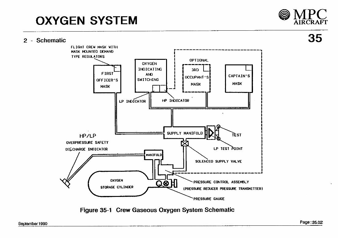
351 - General Description
Flight Crew Oxygen
The crew gaseous oxygen System is schematically shown in figure 35-1 . Each crew Station has a quick-donning mask with a demand regulator installed. The oxygen is supplied from a high pressure oxygencylinder to masks through a pressure regulator / transmitter assembly and distribution circuit.
The crew oxygen System is capable of supplying oxygen whenever the cabin pressurization fails at anyaltitude
The high-pressure portable oxygen cylinder assembly is used by crew members in case of emergencywhen fighting a fire , against the emission of smoke and noxious gas with füll mobility if there is a failureofthefixed crew oxygen System.
Passenger Oxygen Unit
The solid state chemical oxygen dispensing units are mounted above the passenger seats and in lava-tories (fig.35-2). Each mask isprovided with continuous flow of oxygen lasting at least 12 minutesafterflow Initiation.
Attendant Oxygen SystemAbove the attendants Station a two-mask chemical oxygen unit is installed to supply emergency oxygenin case of cabin decompression.Each attendant is equipped with a portable oxygen unit which can be used to provide emergency oxygenand first-aid treatment for passengers.
September 1 990 Pa9e: 35-01
OXYGEN SYSTEM MPCAIRCRAFT
2 - SchematicFLIGHT CREW MASK WITH
HP/LPOVERPRESSURE SAFETY
D&CHARGE INOICATOR
ATORS
H_FIRST
OFFICER'S
MASK
OXYGEN
INDICATINGANO
SW ITCHING
LP INOICATOR
,
p
\L
3RD LOCCUPANT'S CAPTAIN'S
MASK MASK._-!
HP INOICATOR
ri SUPPLY MANIFOLO fcr-»„
OXYGEN
STORAGE CYLINOER
LP TEST POINT
SOLENOID SUPPLY VALVE
PRESSURE CONTROL ASSEMBLY
(PRESSURE REOUCER PRESSURE TRANSMITTER)
'PRESSURE GAUGE
Figure 35-1 Crew Gaseous Oxygen System Schematic
35
September 1990 Page: 35.0Z

OXYGEN SYSTEM MPCAIRCRAFT
35
— key— 2mask units(15)3mask units(20)4mask units(5)
September 1990
Flgure35-2/1 Passenger Oxygen System Distribution
Page ;:35.03/1

OXYGEM SYSTEM MPCAIRCRAFT
- KEY - * = 2MASK UNITSC22)
O = 3MASK UNITS(24)
A = 4MASK UNITS(6)
35
September 1990
FJgure35-2/2 Crew Gaseous Oxygen System Schematic
Page: 35.03/2

PNEUMATIC SYSTEM MPCAIRCRAFT
36
Contents
- General
- Bleed air System
- Engine bleed air supply
- Additional sources of bleed air
September 1990
PNEUMATIC SYSTEM AIRCRAFT
General description 36
Bleed air System
The pneumatic (bleed air) System provides hot compressed air for the followingSystems / functions:
- Air conditioning- De-icing- Engine starting- Hydraulic and water Systems pressurisation
Engine bleed air supply (see figure 36.10)
Each engine has its own bleed air supply control System, normally isolatedfrom each other by the crössfeed valve.Bleed air is drawn from either an intermediate pressure (IP) stage or a highpressure (HP) stage of the engine compressor, depending on flight mode(power setting). In the climb and cruise modes, IP bleed air pressure is high enoughto satisfy system requirements and the HP control valve remains closed.
September 1990 Page : 36.01

PNEUMATIC SYSTEM
In descent mode ( Iow engine power setting ) the l P bleed air pressure is
inadequate for system requirements. The drop in pressure allows the HP
control valve to open. HP stage bleed air then supplies the bleed system,
while isolating the l P stage by ciosing the l P stage check valve.
IP or HP bleed air is consequently passed through the pressure regulator,
overpressure valve and finally the precooler heat exchanger to provide
user Systems with pressure and temperature controlled bleed air.
Additional sources of bleed air are :
- Ground supply unit - via HP ground connector
-TheAPU
Under normal flight conditions the bleed air system functions fully
automatically. A dedicated bleed air monitoring Computer (BMC)
monitors each engine bleed system, and provides indication for crew
action when system faults occur.
September 1990 Page : 36.02

PNEUMATIC SYSTEM MPCAIRCRAFT
ArchiteCture LEFT WING
ENGINt 1£~AN AIR BLEED
AND PYLON
CENTER FUSELAGEWING IGE PRO1ECTION |
s/
/ \
WING ..oln i".• i S
PACK("} lx\E
PRESSUREBLEED /-V-/KL
^-f^fy
NAGEL LEANTI-ICE
1
O*$HIGHPRESSUREBLEED
0
^—.5
l
*•
!
</
W
-\5
\x^
1
NO
'
V
VI
1>
\^RIGHTWING
RIGHT
ENGINt '2
36AND PYLUN
PACK r^"NO
'
l\
SYSTEMPRESSUR1 NATION
4^.
r-4-k>7
',
<^1
FAM ATD X
5^1 EXHAÜSTED (£)>* OVERBOARD ™
TO ^ GROUND STARTER CONNECTOR
i
^fVl PRESSURE CONTROL t.I/\ AND SHUTOFF VALVE
, <$6x-v ^r*> p- 'i A^ \Cx
>.
^>
2
>
e t
R^V>
^
\\^
1 i
\N AIR
EXHAÜSTED A.OVERBOARD V^
,0<
A
o
<fl
\R
1
J 1APU
FAN AIR BLEED]
^A__/^V_S/ N-
INTERMEDIATEPRESSUREBLEED
'ÄV-O^5/^_^
NACELLEANTI-ICE
r '
igK)HIGHPRESSUREBLEED
1t
. HIGH PRESSURE CONTROL VALVE
CONTROL OR SHUTOFF VALVE
CHECK VALVE
FIGURE 36.1ft BLEED AIR SUPPLY-SCHE.MATIC
September 1990
2. PRESSURE REGULATING AND SHUT OFF VALVE
3- OVERPRESSURE VALVE
4. FAN AIR CONTROL VALVE
5. HEAT EXCHANGER (PRECOOLER)
6. CROSSFEED VALVE
Page : 36.03
WATER / WASTE MPCAIRCRAFT
38r
i
Contents
1
2
3
4
5
- General
- Potable Water
- Waste Water
- Waste Disposal
- Air Supply
September 1990 Page: 38.01

WATER / WASTE MPCAIRCRAFT
1. GeneralThe aircraft is equipped with water and waste facilities. The System supplies potablewater for the galleys and lavatories, and the waste disposal Service allows wastewater from the galley and teilet wash basins to drain from the aircraft, via drainmastsfitted at the underside of the fuselage.The teilet waste contents are collected in tanks directiy connected to the teilet flushSystem.
38
2 . Potable WaterThe potable water is stored in a 60 liter (15.5 USgal) reservoir which is installed inthe pressurized underfloor area forward of the centre wing box.The tank is manufactured from glass fibre composite and pressurized from thebleed air System.
September 1990 Page: 38.02

WATER / WASTE
383 . Waste WaterWaste water from the basins in the lavatories and galleys is drained out of theaircraft via two electrical heated drain masts in the forward and aft fuselage.Additional provisions are provided for an optional lavatory and galley.
4. Waste DisposalThe toilet System collects the waste disposal in the waste tanksof the toilet units. The waste tanks are manufactured from glass fibrecompound and are equipped with a filter/pump and a drain valve assembly.During ground Service the tanks are emptied, cleaned and filled with aprescribed quantity of flush-fluid.A Ventilation System for the toilet units prevents odours from coming out ofthe units.
5. Air SupplyThe potable water supply tank is pressurized with pressure regulated andtemperature controlled air from the bleed air System. The air supply linesare equipped with non-return valves to protect against reverse fluid or airflow induction.
September 1990 Pagef 38.03

WATER / WASTE MPCAIRCRAFT
Fig. 38-01
September 1990
LÜ
11
CD
nIIllHHn
mi\
POTABLE WATERWASTE WATER
^^2; UAVATORY WASTELAVATORY FILLINGAND FLUSHING
ELECTRICAL SIGNALAIR PRESSURE
r-T DRAIN MASTWJ ELCTR HEATED
.. ^
>-
Oh-^^T
^^
nMi Ü
l|
i
FLOOR
nr?F°°i inr TPHMBLEED AIR SYSTEM
t
/^
1 '!' !1 i i! /i l —11 T'Hn,,
ii!- n /-LL^
§M
oLüZ
§
1H» M
II ö *SG!-J 3 *< o o; LÜSQQ: a. t-
ZH H Lü <<z in > x>- o < og gO * Lü
1- MLü Z < £0< _J_1 M 3 <> _J(D < Z j-< n< a < o-J U- O O 3! fl.
pn
£ 38O >-1- LÜ
^^ I
^^ ^^
_1 CD
H1 1
j li
1 —II 1
L ( \l SUSßALJ 1 ^]
=d
/^
IJS) i
1 11 i
;LO^X JU
Hn
II iII ''
Ü,Hi1 nnnn
HIIIIIIII
-^ !!
gM Z
O <
Ü! gCJ OZ LJ
_l< > O
S£_, ^tt S3 LÜ_I > o 01(0>M h- Z«
ü:ao:_j<M _JMU.a. LÜ LÜ oo: a o <
t-l-ttQZ CKttQ
£S2ZQ:H z°i fe< oo>- o>- <LüLüOt-H USU Z
ZcQrtiLJOt— UJl— M Z3«jMZ _!<_! nO 1— H- CQQ < (D > — 1 < m*
S 22553 53C ä Pa|e: 38.04

ON-BOARD MAINTENANCE SYSTEM MPCAIRCRAFT
Contents
- General
- Centralized maintenance
- Aircraft condition monitoring
45
ON-BOARD MAINTENANCE SYSTEM
General 45
The on-line maintenance of the electronic Systems is based on the use of the CMS(Centralized Maintenance System), comprising of one CMC (Centralized Maintenance Computer)and an optional printer.
The QMS provides for line- and shop-maintenance a central means to:
Display and interrogate the BITEs of the various Systems
andInitiale tests from the MCDUs (Multipurpose Control Display Units)
located on the centre pedestal (cockpit).
The intelligence required for:
detecting the failures
processing the corresponding maintenance data
formatting messages to be displayed on the MCDUs
is included in each BITE of the avionics Systems.
September 1990 PagöyJ5.01
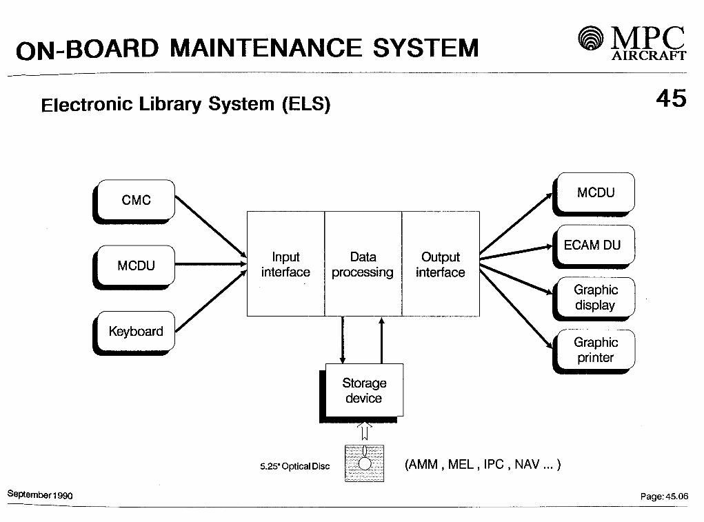
ON-BOARD MAINTENANCE SYSTEM MPCAIRCRAFT
Electronic Library System (ELS) 45
InputInterface
Dataprocessing
OutputInterface
Storagedevice
5.25" Optical Disc (AMM,MEL,IPC,NAV...)
September 1990 Page: 45.06

XIXILIARY POWER UNIT MPCAIRCRAFT
49
Contents
2
3
4
5
6
7
8
General
APU operating envelope
APU Installation
APU Subsystems
APU compartment cooling,Ventilation and drain System
Air intake
Exhaust
Control and monitoring
11990 Page :49.01

AUXILIARY POWER UNIT
1 General 49
The Auxiliary Power Unit (APU) instalied on the MPC 75 is designed to provide bleed air to the aircraftpneumatic System and to drive an oil spray cooled AC generator during ground and in flight Operation,thus increasing aircraft operational flexibility.
Independence of the MPC 75 from external sources on ground (up to 8000 ft) is assured by power availablefrom the APU to drive a 60 kVA generator and additionally to supply bleed air for main engine start or theair conditioning System. During flight Operation the APU is capable of providing electrical powerwithin the whole flight envelope.
This permits dispatch of the aircraft under certain MEL conditions, where together with the in flight restartcapability (up to TBD ft) a considerable increase in redundancy of electrical power is obtained.
Maximum Operation limit of the APU is aircraft ceiling altitude.
SEPTEMBER 1990 Page :49.02

APU MPCAIRCRAFT
APU Performance Comparison for MPC 75 (Sea Level Standard Day)MPC 75 electrical requirement 60 kVA
49
GTCP 36-150
(ATR 72)
(BAe 146-200)
(Fokker 100)
GTCP 36-250
GTCP 36-300(A320)
APIC APS2000(B 737-500)
KHDT218
150(AT) (16 kW)
150M (18.6kW)
150R(35.1 kW)
MPC 75 Bleed Air Requirements
2
(45kW)
(90 kW)
(60kW) (45 kW)
(60 kW)
0.1 0.2 0.3 0.4 0.5 0.6
Bleedairflow
0.7 0.8 0.9
[kg/s]SEPTEMBER 1990

Flight O
peration
O
(O8CD
X30T3Om

AUXILIARY POWER UNIT AIRCRAFT
3 APU Installation 49
The APU is located in the aft fuselage in the tail cone.The housing is arranged principally äs a support and aerodynamic fairing for the APU, air intake Systemand exhaust System.
In accordance with the construction regulations, the APU compartment is arranged äs a fireproof box and isrigidly attached to the fairing structure. The firewalls and the access doors are manufactured from titanium sheet.
There is a pressure relief door to limit the pressure in the APU compartment to a value acceptable for thestructure.
The Installation of the APU is designed for a rapid change, the time for 'quick engine change unit' removaland Installation, ready to start, will not exceed 1 h 15 min.
The APU support is designed according to fail safe principles covering the event of fire.
SEPTEMBER 1990 . Page: 49.06

AUXILIARY POWER UNIT
4 APU Subsystems 49Fuel supply and controlThe APU is supplied with fuel through a separate fuel line, drawing fuel from the LH main engine fuel System.A dedicated APU pump is installed in that line to permit fuel supply to the APU when the engine fuel System is notoperating. Opening of the cross feed valve permits fuel supply from the RH tank to the APU.
An LP valve installed on the tank boundary permits to isolate the APU fuel line when the APU is cut off, thusavoiding pressure on the fuel line across the pressurised zone.
The LP valve is controlled by the APU master switch and closes automatically in case of emergency shut downof the APU.
The fuel control System operates fully automatically controlled and monitored by the APU Control Unit (ACU).
The System provides metered fuel to the APU combustor according to the inputs received from the ACU fortimed acceleration and constant speed control (+ 0.5 per cent N).
SEPTEMBER 1990 Page: 49.08

AUXILIARY POWER UNIT MPCAIRCRAFT
Bleed air System
The bleed air flow is controlled according to aircraft System demand.
Sufficient APU bleed air power is available, while providing electrical power for equipment required for groundOperation, to meet the specified ground air conditioning requirement.
The System is protected against reverse bleed air flow.
A compressor surge control System prevents compressor surge for all operating modes. The surge air isconducted into the APU exhaust.
49
Lubrication and generator cooling
The integral lubrication System for engine, generator and gear box includes an internal gear box oil reservoir,an oil pump assembly and an oil cooler.
By design the oil cooler capacity is sufficient to permit cooling of the oil spray cooled generator with the samecircuit.
The APU operates with the same oil types äs approved for the main engines and their accessories.
SEPTEMBER 1990 Page: 49.10

AUXILIARY POWER UNIT
4Q5 APU compartment cooling/ventilation and drain System
The APU cooling air and Ventilation System provides air for cooling of the APU, equipment on the APU andVentilation of the APU compartment. Cooling air supply is the APU plenum chamber. Cooling air is deliveredto the oil cooler and the APU compartment. Air out of the oil cooler is led to the outside of the aircraft.
After APU shut down Ventilation of the APU compartment is achieved by a louvre in the upper side of theAPU compartment. Free convection provides efficient Ventilation of the APU compartment.
Drainage and leaks from various places are collected in a drain tank and discharged outboard via a drain mast.
SEPTEMBER1990 Page:49.12

AUXILIARY POWER UNIT
6 Air intake
The common air intake for power section, bleed air generation and cooling is designed äs a silencer providinghigh intake pressure recovery.
The air intake is located considering
noise restrictionsicing conditionsdust ingestionre-ingestion of APU exhaust gaseshigh Installation pressure ratio in flight
49
7 Exhaust
The exhaust System is installed in a fire proof compartment separated from the APU compartment.The exhaust System functions äs a silencer. It conducts the not APU exhaust gases to the outside of theaircraft at a location providing high Installation pressure recovery in flight.
SEPTEMBER 1990 Page: 49.14
AUXILIARY POWER UNIT
8 Control and monitoring 49
The central component of the control and monitoring System is the APU Control Unit (ACU). This unit isinstalled in the rear fuselage and is easily accessible.
It uses microprocessor/digital techniques to realise the following functions :
control the Start sequenceregulate the APU speed
- regulate the bleed air flowmonitor all important Operation parametersmonitor the sensor units on the APU to detect the development of a serious faultdrive indications and annunciation to the cockpit and provide adequate Signals to theECAM, FWS, QMSinitiale APU shut down in case of a fault
- control the APU surge System
An RS 232 Interface is provided on the ACU. This allows check out of the ACU circuits in the shop, äs well äsadjustment of the performance Outputs.
The controls to switch on or off the APU and to activate the APU starting sequence are located in the cockpit.The APU Operation is fully automatically controlled by the ACU.
APU monitoring for the flight crew is provided by indications on ECAM.
SEPTEMBER1990 Page:49.16

AUXILIARY POWER UNIT AIRCRAFT
Control and monitoring cont'd 49
For maintenance purposes APU Parameters are provided to the Onboard Maintenance System (OMS).A test button on the cockpit fire panel allows testing of the fire extinguisher circuit äs well äs functional integrityof the fire detection System
Besides the controls in the flight deck emergency shut down of the APU is possible :
- by pushing the APU fire handle- from the nose landing gear APU emergency shut down push-button- automatically on ground after an APU fire is detected
SEPTEMBER 1990 Pa9e: 49'16a
ENGINE CONTROLS MPCAIRCRAFT
73
Contents
General (FADEC)
Engine Control Unit
Engine Interface Vibration Monitoring Unit
September 1990
ENGINE CONTROLS AIRCRAFT
FÜLL AUTHORITY DIGITAL ENGINE CONTROL (FADEC)
G e n e r a l D e s c r i p t i o n
The MPC 75 engines are electronically controlled by the Füll Authority Digital Engine Control (FADEC). Each
engine is equipped with a fully redundant (dual) FADEC System which provides better engine protection and
permanent engine health monitoring.
The application of a FADEC provides advantages to the MPC 75 aircraft. It saves weight, reduces pilot workload
and maintenance cost, saves fuel by dimension free control of the gas generator and allows the Optimum
adaptation of thrust schedules to the aircraft needs.
FADEC is an electronic System which consists of a fully redundant (dual) Engine Control Unit (ECU) and an
(simplex) Engine Interface Vibration Monitoring Unit (EIVMU)) with built in failure .detection. In case of a FADEC,
malfunction, the System Switches to the other channel or an alternate control mode, the best working channel always
being in Charge of engine controls. This ensures engine performance and safety.
September 1990 Page: 73.01
ENGINE CONTROLS AIRCRAFT
FADEC cont. 73
Each engine is equipped with a FADEC which provides:
- gas generator control
- engine limit protection
- engine automatic starting
- fly-by-wire System compatibility
- power management
- failure Identification and indication
- condition monitoring
September1990 ; Page-.73.02
ENGINE CONTROLS
Engine Control Unit (ECU) 73One ECU is located on the engine with dual redundant channels (active and standby) each having separate
aircraft power sources to ensure engine starting on the ground and in flight. In addition dedicated ECU
alternators assure independent power supply.
Dual redundancy for electrical input devices ( Throttle Lever Angle (TLAs), engine sensor Signals, Air Data System
(ADS 1 +2) ).
Dual redundancy for electrical part of control actuator.
The Simplex hydromechanical unit includes:
- the metering valve and servo valves to control the variable Stator position
- the variable bleed valve control System
- the HP turbine active clearance control System actuators
- the fuel System
- the ignition System
- the thrust reverser System
Fault tolerance and fail operational capability.
High level of protection against electromagnetic disturbance.September1990 _ Page: 73.03

ENGINE CONTROLS AIRCRAFT
Engine Interface Vibration Monitoring Unit (EIVMU)
The Interface between the FADEC System and the other aircraft Systems is mainly performed by the EIVMU
through digital data buses.
One EIVMU per engine is located in the avionics bay.
Gare is taken to preserve Systems segregation for safety and integrity.
The EIVMU includes the necessary data processing Provision to make engine parameters available for a condition
monitoring System.
The compatibility with the aircraft fly-by-wire System and incorporation of power management function allows
significant aircraft weight saving and fuel burn reduction.
73
Septembof1990 Page: 73.04

ENGINE CONTROLS MPCAIRCRAFT
Systemsisplay
Engine / Warningsdisplay
Throttle lever angle
ADS 1 +2
ADS1+2 [
Throttle lever angle
Automatic/Manual starting
FMS
FCGC
ENGINEINTERFACEVIBRATION
MONITORINGUNIT
(EIVMU)
EngineControl
Unit(ECU)
CHANNEL A
EngineControl
Unlt(ECU)
CHANNEL* B
Engine sensor Signals
Ground / Flight
Bleed Status
iHydromechanicalfuel unit
Start valve
Thrust ReverserSystem
Ignition System
Engine sensor Signals
73
September 1990Page: 73.05