Embed Size (px)
Citation preview

MP260 Planer MoulderSafety, Operation,
Maintenance & Parts Manual
MP260 A1.00
Safety is our #1 concern! Read and understandall safety information and instructions before oper-ating, setting up or maintaining this machine.
April 2018
Form #2332

© 2019
Printed in the United States of America. All rights reserved. No part of this manual may be reproduced in any form by any photographic, electronic, mechanical or other means or
used in any information storage and retrieval system without written permission from
Wood-Mizer 8180 West 10th Street
Indianapolis, Indiana 46214

Table of Contents Section-Page
MP260 Planer Moulder
SECTION 1 INTRODUCTION 1-1
1.1 About this manual...................................................................................1-11.2 Getting service........................................................................................1-11.3 Warranty .................................................................................................1-3
SECTION 2 SAFETY 2-1
2.1 Safety instructions ..................................................................................2-1Owner’s Responsibility..........................................................2-1
2.2 Safety symbols........................................................................................2-12.3 Electrical lockout procedures .................................................................2-4
SECTION 3 SETUP 3-1
3.1 Site preparation.......................................................................................3-1Chip collection ......................................................................3-2Feed tables (optional) ...........................................................3-3Electrical .........................................................................3-5
3.2 Checking rotation direction ....................................................................3-83.3 Setup of upper and lower cutter heads .................................................3-10
Leveling lower cutter straight planer knives.......................3-12Initial setup of upper cutter.................................................3-15Leveling the upper cutter straight planer knives ................3-16Replacing cutter straight planer knives ..............................3-17Adjusting cutting depth of the lower cutter .........................3-17Adjusting upper cutter depth...............................................3-19Moulding knives in upper and lower cutters.......................3-20
3.4 Side cutter setup ...................................................................................3-21Setting the movable side cutter head...................................3-27
3.5 Feed rollers ...........................................................................................3-29Adjusting the feed roller pressure .......................................3-29Adjusting the feeding speed.................................................3-30
3.6 Leveling the machine table...................................................................3-303.7 Running the first test board ..................................................................3-32
Side cutter fence setup.........................................................3-33
SECTION 4 OPERATION 4-1
4.1 Operation ................................................................................................4-14.2 Planing tips .............................................................................................4-3
General recommendations ....................................................4-3Sizing stock .........................................................................4-4Planing narrow stock ............................................................4-5Planing stock thicker than 2 Inches ......................................4-5Saving a moulding pattern ....................................................4-5Tongue and groove ................................................................4-6
Table of Contents WMdoc072519 iii
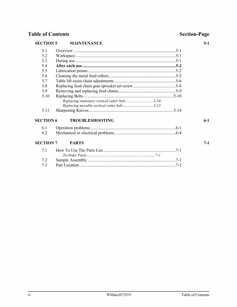
Table of Contents Section-Page
SECTION 5 MAINTENANCE 5-1
5.1 Overview ................................................................................................5-15.2 Workspace ..............................................................................................5-15.3 During use ..............................................................................................5-15.4 After each use........................................................................................5-25.5 Lubrication points...................................................................................5-25.6 Cleaning the metal feed rollers...............................................................5-55.7 Table lift assist chain adjustments..........................................................5-65.8 Replacing feed chain gear sprocket set screw ........................................5-85.9 Removing and replacing feed chains......................................................5-95.10 Replacing Belts.....................................................................................5-10
Replacing stationary vertical cutter belt.............................5-10Replacing movable vertical cutter belt ...............................5-12
5.11 Sharpening Knives................................................................................5-14
SECTION 6 TROUBLESHOOTING 6-1
6.1 Operation problems ................................................................................6-16.2 Mechanical or electrical problems..........................................................6-4
SECTION 7 PARTS 7-1
7.1 How To Use The Parts List ....................................................................7-1To Order Parts.......................................................................7-1
7.2 Sample Assembly ...................................................................................7-17.3 Part Location ..........................................................................................7-2
iv WMdoc072519 Table of Contents

IntroductionAbout this manual 1
SECTION 1 Introduction
1.1 About this manual
Congratulations on your purchase of a Wood-Mizer Planer Moulder! When properlymaintained and operated, your Planer Moulder should give you many years of depend-able service.
CAUTION! Read this entire manual beforeoperating the equipment. Take notice of all safetywarnings throughout this manual and thoseposted on the equipment. Keep this manual withthis equipment at all times, regardless of owner-ship.
Read all additional manufacturer’s manuals and observe anyapplicable safety instructions including dangers, warnings, andcautions.
Only persons who have read and understood the entire operator's manual should operatethe Wood-Mizer Planer Moulder. The Planer Moulder is not intended for use by or aroundchildren.
1.2 Getting service
Wood-Mizer is committed to providing you with the latest technology, highest qualityequipment, and strongest customer service available on the market today. We continuallyevaluate our customers’ needs to ensure we’re meeting current wood-processingdemands. Your comments and suggestions are welcome.
GENERAL CONTACT INFORMATION
Toll free phone numbers are listed below for the continental U.S. and Canada. See thenext page for contact information for more Wood-Mizer locations.
United States Canada
Sales 1-800-553-0182 1-877-866-0667
Service 1-800-525-8100 1-877-866-0667
Website www.woodmizer.com www.woodmizer.ca
E-mail [email protected] [email protected]
Introduction doc072519 1-1

IntroductionGetting service1
Office Hours: All times are Eastern Standard Time.
Please have equipment serial number and your customer number ready when you call.
Wood-Mizer will accept these methods of payment:
Visa, Mastercard, or Discover
COD
Prepayment
Net 15 (with approved credit)
Be aware that shipping and handling charges may apply. Handling charges are based onsize and quantity of order. In most cases, items will ship on the day they are ordered.Second Day and Next Day shipping are available at additional cost.
If your Planer Moulder was purchased outside of the United States or Canada, contact thedistributor for service.
WOOD-MIZER LOCATIONS
For a complete list of dealers, visit www.woodmizer.com.
Monday - Friday Saturday(Indianapolis Office Only)
Sunday
8 a.m. to 5 p.m. 8 a.m. to 12 p.m. Closed
USA World Headquarters Canadian Headquarters
Serving North & South America, Oceania, East Asia
Wood-Mizer LLC8180 West 10th StreetIndianapolis, IN 46214
Phone: 317.271.1542 or 800.553.0182Customer Service: 800.525.8100
Fax: 317.273.1011Email: [email protected]
Serving Canada
Wood-Mizer Canada396 County Road 36, Unit B
Lindsay, ON K9V 4R3
Phone: 705.878.5255 or 877.357.3373Fax: 705.878.5355
Email: [email protected]
1-2 doc072519 Introduction

IntroductionWarranty 1
1.3 Warranty
Wood-Mizer® LLCLimited Product Warranty
Wood-Mizer LLC (“Warrantor”), an Indiana corporation with its principal place of businessat 8180 West Tenth Street, Indianapolis, IN 46214-2400 USA, warrants to the purchaser(“Purchaser”) that for the time periods specifically stated herein and subject to the terms,conditions and limitations stated herein, the equipment manufactured by the Warrantorwill be free from defects in material and workmanship attributable to Warrantor so long as,during the warranty periods stated herein, the equipment is installed, operated and main-tained in accordance with the instructions provided by Warrantor.
Brazilian Headquarters European Headquarters
Serving BrazilWood-Mizer do Brasil
Rua Dom Pedro 1, No: 205 Bairro: Sao JoseIvoti/RS CEP:93.900-000
Tel: +55 51 9894-6461/ +55 21 8030-3338/ +55 513563-4784
Email: [email protected]
Serving Europe, Africa, West Asia
Wood-Mizer Industries Sp z o.o.Nagorna 114
62-600 Kolo, Poland
Phone: +48.63.26.26.000Fax: +48.63.27.22.327
PRODUCT MODEL CLASSLENGTH OF WARRANTY
EFFECTIVE DATEUSA & CANADA
NON USA & CANADA
Portable Sawmills, Resaws, Edgers
LT, HR, EG, LX Two years One year
Date of purchase Portable Sawmills with Chassis
LT28, LT35, LT40, LT50, LT70, LX450
Two years, excluding the chassis; chassis shall have a five year warranty
One year
Industrial Sawmills, Resaws, Edgers
WM, HR, EG, TVS, SVS, FS
One year One yearDate of purchase or date of installation / training (if applicable), whichever occurs first, not to exceed 6 months from date of purchase
Material HandlingTWC, IC, TD, LD, GC, CR, CB, CC
One year One year
Introduction doc072519 1-3

IntroductionWarranty1
EXCLUSIONS FROM 90 DAY, LIMITED ONE YEAR AND TWO YEAR WARRANTY
Warrantor shall have no responsibility under this warranty for any wear components,including, but not limited to: belts, blade guides, blades, electric motor brushes, drumswitches, filters, fuses, hoses, bearings (excluding cylindrical drive bearings), bushings,cable carriers, and spark plugs. All wear components are furnished “as is”, without anywarranty from Warrantor. This limited warranty does not cover any defects caused bymisuse, negligence, alterations, damage due to overload, abnormal conditions, excessiveoperation, accident, or lack of performance of normal maintenance services.
Several components which are used in the manufacture of the equipment but not manu-factured by Warrantor, such as cant hooks, power plants, laser sights, batteries, tires, andtrailer axles have warranties provided by the original equipment manufacturer (writtencopies available upon request). Warrantor does not separately warrant such items. Com-ponents or equipment manufactured by third parties are not covered by this warranty.Warrantor, however, will provide reasonable assistance to the Purchaser to make claimsagainst any warranties applicable to such component parts as provided by such originalequipment manufacturers. Components or equipment manufactured by third parties arenot covered by this Warranty.
FIVE YEAR LIMITED CHASSIS WARRANTY
The limited five year chassis warranty, described above, DOES NOT extend to (a) anydamage stemming from accident, improper towing, overload, abuse, misuse, abnormalconditions, negligence, excessive operation, or lack of maintenance, (b) rust caused byexposure to corrosive atmospheric conditions, or (c) the sawmill head, carriage, axle,brakes, or any hydraulic or electrical components attached to the chassis.
WARRANTOR’S OBLIGATIONS AS TO DEFECTS
In the event that the equipment fails to perform due to defective materials or workmanshipattributable to Warrantor under normal use and service within the established warrantyperiod, Purchaser’s sole and exclusive remedy and Warrantor’s sole liability shall be to
Planer Moulder PD One year One year
Date of purchase
Blade Maintenance Equipment BMS, BMT, BMST One year One year
Options and Accessories Various One year* One year 1
Moulders, Kilns MP, SD One year One year
Replacement Parts Various 90 days 90 days
1 Warranty on Options will match the warranty on the primary equipment when purchased on same invoice.
1-4 doc072519 Introduction

IntroductionWarranty 1
replace or repair, in Warrantor’s sole and subjective discretion, any defective part at War-rantor’s principal place of business without cost to the Purchaser if such defect exists.The determination of whether a product is defective shall be made by Warrantor in War-rantor’s sole and subjective discretion. The Purchaser must notify Warrantor prior to ship-ping any defective part. Warrantor, at its sole discretion, may cover expenses incurred inshipping the defective part to Warrantor for evaluation; provided, however, that Warrantorwill not be responsible for labor, travel time, mileage, removal, installation, and/or inciden-tal or consequential damages. However, any part in excess of 140 pounds must bereturned by the Purchaser to the Warrantor’s nearest authorized facility at the Pur-chaser’s expense, if return is requested by Warrantor. Warrantor shall have a reasonabletime within which to repair or replace the defective part. If Warrantor determines that theproduct is not defective under the terms of this warranty in Warrantor’s sole and subjec-tive discretion, then Purchaser shall be responsible for any expenses incurred by Warran-tor in returning the equipment to the Purchaser.
LIMITATIONS AND DISCLAIMERS OF OTHER WARRANTIES
EXCEPT FOR THE EXPRESS WARRANTY PROVISIONS STATED ABOVE, WARRAN-TOR DISCLAIMS ALL WARRANTIES, EXPRESS AND/OR IMPLIED, INCLUDING ANDWITHOUT LIMITATION, THE IMPLIED WARRANTIES OF MERCHANTABILITY, ANDFITNESS FOR A PARTICULAR PURPOSE, NONINFRINGEMENT AND TITLE. No rep-resentation or other affirmation of fact by representatives of Warrantor, whether verbal orin writing, including photographs, brochures, samples, models, or other sales aids, shallconstitute a warranty, or any other basis, for any legal action against Warrantor. There areno other representations, promises, agreements, covenants, warranties, guarantees, stip-ulations or conditions, expressed or implied, by Warrantor, except as expressly set forthherein. THE ORIGINAL PURCHASER AND ANY INTENDED USER OR BENEFICIARYOF THIS EQUIPMENT, SHALL NOT BE ENTITLED TO RECOVER ANY INDIRECT,SPECIAL, PUNITIVE, EXEMPLARY, CONSEQUENTIAL, SPECIAL, OR INCIDENTIALDAMAGES OR LOSES, INCLUDING BUT NOT LIMITED TO, DAMAGES OF LOSTPRODUCTION, LOST REVENUE, LOST PRODUCT, LOST PROFITS, LOST BUSI-NESS, LOSS OF USE, LOSS OF GOODWILL, OR BUSINESS INTERRUPTION, FROMWARRANTOR FOR ANY REASON WHATSOEVER INCLUDING, WITHOUT LIMITA-TION, WARRANTY OR DEFECT IN THE PRODUCT REGARDLESS OF THE SOLE,JOINT, AND/OR CONCURRENT NEGLIGENCE, BREACH OF CONTRACT, BREACHOF WARRANTY, STRICT LIABILITY IN TORT OR STATUTORY CLAIMS, OR OTHERLEGAL FAULT, OR RESPONSIBILITY OF EITHER WARRANTOR OR PURCHASER ORITS EMPLOYEES OR AGENTS. Warrantor does not warrant that its equipment meets orcomplies with the requirements of any particular safety code or governmental require-ments.
Defective items, replaced under the terms of this warranty, become the property of War-rantor.
Introduction doc072519 1-5

IntroductionWarranty1
DESIGN CHANGES
Warrantor reserves the right to change the design of its products from time to time withoutnotice and without obligation to make corresponding changes in or to its products previ-ously manufactured.
RIGHTS OF PURCHASERS
The validity and effect of this limited warranty, as well as its interpretation, operation andeffect, shall be determined exclusively by the principles of law and equity of the State ofIndiana, USA. This limited warranty gives Purchaser specific legal rights. Purchaser mayalso have other rights, which may vary from state to state. Some states may not allow lim-itations as to the duration of implied warranties or to the exclusion or limitation of inciden-tal or consequential damages, therefore some of the limitations and exclusions detailedset forth above may not apply. In the event that any one or more of the provisions of thiswarranty shall be or become invalid, illegal or unenforceable in any respect, the validity,legality and enforceability of the remaining provisions of this warranty shall not beaffected thereby.
INTERPRETATIONS
This Warranty constitutes the entire warranty agreement between Warrantor and Purchaser andsupersedes any prior understandings or agreements pertaining to the same subject matter. Thiswarranty cannot be amended, except in writing, which refers to this warranty that is signed by bothWarrantor and Purchaser.
Effective: January 1, 2018
© 2018 Wood-Mizer LLC – 8180 West 10th Street, Indianapolis, IN 46214
1-6 doc072519 Introduction

SafetySafety instructions 2
SECTION 2 Safety
2.1 Safety instructions
Owner’s Responsibility
IMPORTANT! It is always the owner's responsibility to comply withall applicable safety instructions, as well as federal, state and locallaws, rules and regulations regarding the ownership and operation ofyour Wood-Mizer Planer Moulder. All Wood-Mizer Planer Moulderowners should be thoroughly familiar with all applicable safety instruc-tions and laws and comply with them fully while using or towing thePlaner Moulder.
WARNING! Clean sawdust from all guards, vents, con-trol boxes, or any area where sawdust may gather afterevery shift. Failure to do so may result in fire, causingdeath or serious injury.
NOTE: ONLY safety instructions regarding personal injury are listed in this section. Safetyinstructions regarding only equipment damage appear where applicable throughout the manual.
2.2 Safety symbols
The following symbols and signal words call your attention to instructions concerning yourpersonal safety. Be sure to observe and follow these instructions.
DANGER! indicates an imminently hazardous situation which, if notavoided, will result in serious injury or death.
WARNING! suggests a potentially hazardous situation which, if notavoided, could result in serious injury or death.
CAUTION! refers to potentially hazardous situations which, if notavoided, may result in minor or moderate injury or damage to equip-ment.
Safety doc072519 2-1

SafetySafety symbols2
IMPORTANT! indicates vital information.
NOTE: gives helpful information.
OBSERVE SAFETY INSTRUCTIONS
IMPORTANT!
Keep children away from the area.
Read the entire operator's manual before operating the PlanerMoulder.
Take notice of all safety warnings throughout this manual andthose posted on the machine.
Keep this manual with this machine at all times, regardless of ownership.
Read all additional manufacturer’s manuals.
Obey all applicable safety instructions including dangers, warnings, and cautions.
Only persons who have read and understood the entire operator's manual shouldoperate the Planer Moulder.
WEAR SAFETY CLOTHING
WARNING! Secure all loose clothing and jewelry before operating thePlaner Moulder. Failure to follow this may result in serious injury ordeath.
WARNING! Always wear eye, ear, and footprotection when operating the PlanerMoulder. Failure to follow this may result inserious injury or death.
WARNING! Wear hand protection whileservicing the Planer Moulder knives. Failureto follow this may result in serious injury ordeath.
2-2 doc072519 Safety

SafetySafety symbols 2
PLANER MOULDER SETUP
DANGER! Do not operate the Planer Moulder without all covers andguards in place. Failure to follow this may result in serious injury ordeath.
WARNING! Set up the planer moulder on solid, level ground. Failure tofollow this may result in serious injury or death.
WARNING! Do not stand in line with the workpiece when it is being fedinto the machine; boards (kickbacks) or other objects may be thrownfrom the machine. Failure to follow this may result in serious injury ordeath.
KEEP HANDS AWAY
DANGER! Remove power before clearing debris or any other mainte-nance activity. Failure to follow this will result in serious injury or death.
DANGER! Never place your hands or tools above or beneath themachine table while the machine is running. Failure to follow this willresult in serious injury or death.
WARNING! Avoid contact with any hot parts (motors). Failure to followthis may result in serious injury or death.
Allow the system to cool sufficiently before beginning any ser-vice function, including debris removal.
WARNING! Avoid contact with sharp edges ofthe cutting knives. Failure to follow this mayresult in serious injury or death.
KEEP PLANER MOULDER AND AREA AROUND PLANER MOULDER CLEAN
DANGER! Maintain a clean and clear path forall necessary movement around the Planer Moulder and materialstacking areas. Failure to follow this will result in serious injury ordeath.
WARNING! Do not allow children in the area of the Planer Moulder.Failure to follow this may result in death or serious injury
Safety doc072519 2-3

SafetyElectrical lockout procedures2
DISPOSE OF WOOD BY-PRODUCTS PROPERLY
IMPORTANT! Properly dispose of all wood by-products, includingsawdust, chips, and other debris, including operation waste such asoil, filters, etc.
KEEP SAFETY LABELS IN GOOD CONDITION
IMPORTANT! Ensure that all safety decals are clean and readable.Replace all damaged safety decals to prevent personal injury or dam-age to the equipment. Contact your local distributor, or call your Cus-tomer Service Representative to order more decals.
IMPORTANT! If replacing a component that has a safety decal affixedto it, ensure the new component also has the safety decal affixed.
2.3 Electrical lockout procedures
RULES FOR USING LOCKOUT PROCEDURE
The equipment shall be locked out to protect against accidental or inadvertent operationwhen such operation could cause injury to personnel. Do not attempt to operate anyswitch or valve bearing a lock. Lockout procedures must be used during:
Changing or adjusting blades Electrical maintenance
Unjamming operations Retrieval of tools/parts from work area
Cleaning Activities where guards or electrical panel guard is open or removed
Mechanical repair
2-4 doc072519 Safety

SafetyElectrical lockout procedures 2
Maintenance hazards include:
Failure to lockout may result in:
To control maintenance dangers:
Lockout procedures must be followed (see OSHA regulation 1910.147).
Never rely on machine stop control for maintenance safety (emergency stops, on/offbuttons, interlocks).
Do not reach into moving blades or feed systems. Allow all coasting parts to cometo a complete stop.
Electrical power supply must be locked out.
Where established lockout procedures cannot be used (electrical troubleshooting ormechanical dynamic troubleshooting), alternative effective protective techniquesshall be employed which may require special skills and planning.
Always follow safe operations practices in the workplace.
LOCKOUT PROCEDURE
Lockout procedures per OSHA regulation 1910.147, appendix A:
GENERAL
The following simple lockout procedure is provided to assist owner/operators in develop-ing their procedures so they meet the requirements of OSHA regulation 1910.147. Whenthe energy isolating devices are not lockable, tagout may be used, provided theowner/operator complies with the provisions of the standard which require additional
Blade contact Missiles (thrown blades/wood chips)
Pinch points Electrical
Kickbacks
Cut Serious injury and death
Crush Amputation
Blindness Burn
Puncture Shock
Electrocution
Safety doc072519 2-5

SafetyElectrical lockout procedures2
training and more rigorous periodic inspections. When tagout is used and the energy iso-lating devices are lockable, the owner/operator must provide full operator protection (seeOSHA regulation 1910.147, paragraph (c)(3)) and additional training and more rigorousperiodic inspections are required. For more complex systems, more comprehensive pro-cedures may need to be developed, documented, and utilized.
PURPOSE
This procedure establishes the minimum requirements for the lockout of energy isolatingdevices whenever maintenance or servicing is done on machines or equipment. It shallbe used to ensure that the machine or equipment is stopped, isolated from all potentiallyhazardous energy sources and locked out before personnel perform any servicing ormaintenance where the unexpected energization or start-up of the machine or equipmentor release of stored energy could cause injury.
COMPLIANCE WITH THIS PROGRAM
All personnel are required to comply with the restrictions and limitations imposed uponthem during the use of lockout. The authorized personnel are required to perform thelockout in accordance with this procedure. All operators, upon observing a machine orpiece of equipment which is locked out to perform servicing or maintenance shall notattempt to start, energize, or use that machine or equipment.
SEQUENCE OF LOCKOUT
1. Notify all affected personnel that servicing or maintenance is required on a machine orequipment and that the machine or equipment must be shut down and locked out to per-form the servicing or maintenance.
2. The authorized employee shall refer to the company procedure to identify the type andmagnitude of the energy that the machine or equipment utilizes, shall understand the haz-ards of the energy, and shall know the methods to control the energy.
3. If the machine or equipment is operating, shut it down by the normal stopping procedure(depress the stop button, open switch, close valve, etc.).
4. De-activate the energy isolating device(s) so that the machine or equipment is isolatedfrom the energy source(s).
5. Lock out the energy isolating device(s) with assigned individual lock(s).
6. Stored or residual energy (such as that in capacitors, springs, elevated machine mem-bers, rotating flywheels, hydraulic systems, and air, gas, steam, or water pressure, etc.)must be dissipated or restrained by methods such as grounding, repositioning, blocking,bleeding down, etc.
2-6 doc072519 Safety

SafetyElectrical lockout procedures 2
7. Ensure that the equipment is disconnected from the energy source(s) by first checkingthat no personnel are exposed, then verify the isolation of the equipment by operating thepush button or other normal operating control(s) or by testing to make certain the equip-ment will not operate.
CAUTION! Return operating control(s) to neutral or "off" position afterverifying the isolation of the equipment.
8. The machine or equipment is now locked out.
RESTORING EQUIPMENT TO SERVICE
When the servicing or maintenance is completed and the machine or equipment is readyto return to normal operating condition, the following steps shall be taken.
1. Check the machine or equipment and the immediate area around the machine to ensurethat nonessential items have been removed and that the machine or equipment compo-nents are operationally intact.
2. Check the work area to ensure that all personnel have been safely positioned or removedfrom the area.
3. Verify that the controls are in neutral.
4. Remove the lockout devices and reenergize the machine or equipment.
NOTE: The removal of some forms of blocking may require re-energi-zation of the machine before safe removal.
5. Notify affected personnel that the servicing or maintenance is completed and the machineor equipment is ready for use.
PROCEDURE INVOLVING MORE THAN ONE PERSON
In the preceding steps, if more than one individual is required to lock out the equipment,each shall place his own personal lock on the energy isolating devices.
Safety doc072519 2-7

SetupSite preparation3
SECTION 3 SETUP
3.1 Site preparation
WARNING! Have a certified electrician install the power to your machine. Failure to follow this may result in serious injury or death.
WARNING! Be sure the power supply cables are not a trip hazard. Failure to follow this may result in serious injury or death.
CAUTION! Improper voltage will cause damage to the motor and elec-tronic components. Have a qualified electrician install the power supply to begin using your pallet dismantler.
IMPORTANT! The power supply must meet the motor specifications concerning wire size, fused disconnect, and voltage, which are pro-vided in the motor’s manual. The electrical installation must also meet local codes.
Your MP260 should be placed in a dry work area on a firm, level surface.
Ensure proper lighting is available, with attention to extra lighting directly over the planermoulder.
Allow room for the longest piece of material to run through and exit the machine with easeof movement.
Allow space for storing and handling the material that will be running through your planer.
The machine may not be used in temperatures below freezing [32°F (0°C)].
Do not allow the power cables or chip collection hoses to become trip hazards. Plan theroutes carefully.
For mounting, you can either bolt the planer moulder to the floor in place with 8-10 mmbolts (recommended) or mount the planer moulder on casters for ease of moving.
IMPORTANT! Only use casters that are approved for this model.
NOTE: If a caster set is fitted to the machine, ensure the floor is flat and level. Make reliable barriers between the machine and differences in floor level or inclined floor surfaces to prevent the machine from accidentally moving due to gravity.
3-1 doc072519 Setup

SetupChip collection 3
The safety distance for persons other than the operator is 10 ft (3 m) from the sides of themachine or 26 ft (8 m) from the in- and outfeed sides during operation. Use some kind ofdemarcation so that no one can unintentionally come within the risk area.
See Figure 3-1.
Onsite setup
DANGER! Maintain a clean and clear path for all necessary movement around the planer moulder and material stacking areas. Failure to fol-low this will result in serious injury or death.
WARNING! Do not allow children in the area of the planer moulder. Failure to follow this may result in serious injury or death.
WARNING! Set up the planer moulder on firm, level ground. Failure to follow this may result in serious injury or death.
Chip collection
The MP260 has 4 chip collection ports--one 5” and three 4” ports--sized to fit flexiblehose, one located at each cutter head. A strong vacuum or chip collection system rateapproximately 2500 CFM is recommended for use on standard materials less than 4”thick. For thicker material or extra-wide planks, size your collection system accordingly.Wood-Mizer sells chip extraction units specially made for this model.
When using a collection system, keep in mind:
Check your local waste disposal codes before designing your chip collection sys-tem.
Design access to your chip collection bins so that they can be easily emptied. Short hose runs and smooth-walled hoses reduce suction loss within the system.
FIG. 3-1
10 ft (3m)
26 ft (8m)
MMP001
MP260
10 ft (3m)
26 ft (8m)
Highest Risk Area Operator’s
Station
Non-operators safe distance area
Infeed Outfeed
Setup doc072519 3-2

SetupFeed tables (optional)3
Locate the chip collector controls near the planer moulder controls. Collection systems are loud; use ear protection. If you are operating this machine in a climate-controlled building and blowing the
chips outside, the vacuum created by the chip collector can quickly empty yourbuilding of its heated or cooled air.
If blowing the chips to an indoor bin, an air filter will be necessary to prevent wooddust from reducing the air quality inside of your building.
If selling chips for use with livestock, do not use harsh chemicals for cleaning orlubricating machinery.
Feed tables (optional)
The in- and out-feed tables are both mounted the same way. The instructions belowdescribe mounting of the in-feed table. This procedure is facilitated if you have someonethat helps you.
MOUNTING
1. Place a straight board in the machine and let it protrude over the in-feed table.
2. Secure the board by raising the machine table.
3. Loosen the screws and press the feed table up against the board.
4. Tighten.
5. Loosen the screws and adjust the angle of the table.
6. Fit the upper angle iron with screws in the threaded holes behind the front edge of themachine table (two M8 washers, two M8x20 screws).
7. Fit the feed table iron angle to the upper iron angle (four M8 washers, two M8x20 screws,two M8 nuts).
8. Fit the lower iron angle to the machine chassis, using the M6 Allen screws that alreadyare screwed in the holes in the chassis.
9. Fit the two forks in the lower angle iron’s oval holes (two M8 washers, two M8 nuts).
10. Fit the table support in the forks (four special nuts, two threaded bars).
11. Fit the struts to the outer sides of the table support (four special nuts, two M8 washers, two threaded bars).
3-3 doc072519 Setup

SetupFeed tables (optional) 3
12. Lift up the table support so that its rounded support surface comes on a level with themachine table.
NOTE: If you are mounting the feed tables single-handed: prop up the table support in a reliable way, e.g. with boards. Place the feed table on the table support and fold up the struts so that they reach the feed table angle iron on the inner side of the feed table. Fasten the struts and the feed table to the feed table iron angle (two special nuts, two M8 washers, two M8x12 screws).
SETTING THE FEED TABLES
1. Loosen the screws holding the feed table iron angle (in front of the machine table) just somuch that the feed table can move vertically.
2. Place a level object on the adjusting plates in front of the lower cutter, and adjust thewhole front edge of the feed table upwards until it is on a level with the adjusting plates,then tighten the screws. (When adjusting the out-feed table, measure against themachine table behind the upper cutter.)
3. Loosen the nuts holding the forks, so that the forks can move.
WARNING! Use cautions to avoid crushing fingers or hands when the screws are loosened. Failure to follow this may result in serious injury.
4. Remove the boards propping up the table support, if you have used such.
5. Move the forks outwards, from the machine chassis, until the outer edge of the feed tableis on a level with the machine table.
To facilitate this adjustment you can use wooden wedges, shims, or the like, between theforks and the machine chassis. This helps pushing the forks from the chassis until thedesired feed table height is obtained.
6. Ensure that the forks are aligned with the table support.
7. Tighten the nuts.
READJUSTING THE FEED TABLES
In some cases it can be of benefit that the outer ends of the feed tables are somewhathigher (1-10 mm or 0.04-0.4”) than the machine table, to diminish the occurrence of in-and out-feed snipes on the work pieces. This is especially important when thin or softwork pieces are processed. The outer ends of the feed table should never be lower thanthe machine table.
Setup doc072519 3-4

SetupElectrical3
The in-feed table has to be adjusted when the cutting depth of the lower cutter has beenchanged by adding or removing adjusting plates.
NOTE: The special nuts and screws that hold the feed table angle iron can be replaced by M10 nuts and M10 screws after you have adjusted the feed table. When these screws are tightened, the lateral play of the feed table will be reduced. This can be of interest if, for instance, a lon-ger (custom-made) fence for jointing operation with the first side cutter is to be mounted on the in-feed table.
Electrical
Depending on your model, the MP260 planer runs on:
The planer normally draws between 18 and 32 amps during operation.
If you need a 3-phase converter for your installation, size it for 60 Amp, 220 Volt, with a 20HP motor.
ELECTRICAL BREAKER BOX ON THE MP260
WARNING! Have a certified electrician install the power to your machine. Failure to follow this may result in serious injury or death.
The electric supply is routed into the electrical breaker box on the back of the MP260.This box has a protective cover, and inside there are four 3-pole 16-amp circuit breakers,one for each motor. Each one of the circuit breakers is shared between one motor and thesmall feed motor.
1. Attach three voltage leads to L1, L2, and L3.
2. Route the four wires (three power, one ground) through the access hole located on theside of the box.
3. Route the ground wire to the green ground bar found in the electric breaker box.
Route the four wires (three power, one ground) through the access hole located on theside of the box.
MP260EC 400-440V 3Ph 16-32A service
MP260EB 230V 3Ph 20-32A service
MP260EA 230V 1Ph 50A service
3-5 doc072519 Setup
SetupElectrical 3
SINGLE PHASE SCHEMATIC
L3 T3
L2 T2
L1 T1
A1 A2
3
4
4 345
L3 T3
L2 T2
L1 T1
A1 A2
4 345
L3 T3
L2 T2
L1 T1
A1 A2
4 345
5
6
MOTOR1
MOTOR2
MOTOR3
9
ELECTRICAL MAIN BOX MANOUVER BOX
WHITE LAMPVOLTAGE ON
ONON
GROUND
HORIZONTAL UNDER CUTTER
THERMO SWITCHCONT.
CONT.
CONT.YELLOW/GREEN
ON
THERMO SWITCHCONT.
CONT.
CONT.YELLOW/GREEN
ON
RIGHT VERTICAL CUTTER
A1 A2
2
1
L3 T3
L2 T2
L1 T1
A1 A2
4 345
MOTOR
8
5
L3 T3
L2 T2
L1 T1
4 345
MOTOR4
THERMO SWITCHCONT.
CONT.
CONT.YELLOW/GREEN
ON
LEFT VERTICAL CUTTER
WHITE LAMPON
WHITE LAMPON
WHITE LAMPON
THERMO SWITCHCONT.
CONT.
CONT.YELLOW/GREEN
ONWHITE LAMP
ON
HORIZONTAL UPPER CUTTER
THERMO SWITCHCONT.
CONT.
CONT.YELLOW/GREEN
OFF
EMERGENCY STOP
WHITE LAMP
7
TOP DOOR SWITCH
FEEDING MOTOR
L1N
2
1
2
1
2
1
2
1
2
1
FUSE 16
FUSE 1 A
FUSE 1 A
ELECTRICAL SCHEMATIC MP260, 230 VOLT 1-PHASE, UL
K1 18
K2 18
K3 18
K4 32
K5 9
Total power 10 kWConnect to 230 V, 1-phaseConnect the cable from the machine Fuse 50 Amp
A (x2)
FUSE 16 A (x2)
FUSE 16 A (x2)
FUSE 20 A (x2)
to a security main switch.
Setup doc072519 3-6

SetupElectrical3
3 PHASE SCHEMATIC
L3 T3
L2 T2
L1 T1
A1 A2
3
4
4 3
3
2
1
45
L3 T3
L2 T2
L1 T1
A1 A2
4 3
3
2
1
45
L3 T3
L2 T2
L1 T1
A1 A2
4 3
3
2
1
45
5
6
MOTOR1
MOTOR2
MOTOR3
9
K1 18
K2 18
K3 18
L1L2
L3 ELECTRICAL MAIN BOX MANOUVER BOX
WHITE LAMP
VOLTAGE ON
ONON
Ground
HORIZONTAL UNDER CUTTER
THERMO SWITCH
CONT.
CONT.
CONT.YELLOW/GREEN
ON
THERMO SWITCH
CONT.
CONT.
CONT.YELLOW/GREEN
ON
RIGHT VERTICAL CUTTER
A1 A2K4 25
2
1
L3 T3
L2 T2
L1 T1
A1 A2
4 3
3
2
1
45
MOTOR
K5 98
5
L3 T3
L2 T2
L1 T1
4 3
3
2
1
45
MOTOR4
THERMO SWITCH
CONT.
CONT.
CONT.YELLOW/GREEN
ON
LEFT VERTICAL CUTTER
WHITE LAMPON
WHITE LAMP
ON
WHITE LAMP
ON
THERMO SWITCH
CONT.
CONT.
CONT.YELLOW/GREEN
ON
WHITE LAMP
ON
HORIZONTAL UPPER CUTTER
THERMO SWITCH
CONT.
CONT.
CONT.YELLOW/GREEN
OFF
EMERGENCY STOP
WHITE LAMP
7
TOP DOOR SWITCH
FUSE 16 A (x3)
FUSE 16 A (x3)
FUSE 20 A (x3)
Total power 13.4 kWConnect to 230 V, 3-phaseConnect the cable from the machine to a security main switch.Fuse 50 Amp
ELECTRICAL DRAWING PH260, 230 VOLT 3-PHASE
FEED MOTOR
FUSE 16 A (x3)
FUSE 1 A
FUSE 1 A
3-7 doc072519 Setup

SetupChecking rotation direction 3
INSTALLATION FOR 3-PHASE POWER
WARNING! Have a certified electrician install the power to your machine. Failure to follow this may result in serious injury or death.
The MP260 Planer is designed to run on 230V 3-phase AC power. If you need a 3-phaseconverter for your installation, size it for 60 Amp, 220 Volt, with a 20 HP motor
The planer draws between 10 and 32 amps when a board is passing through it, depend-ing operating conditions. The planer needs 25-32 amp service.
The electrical connections are made inside the electrical control box on the side of themachine.
Remove the cover of the control box, and place it where it will not be damaged.
There is an attached label that reads L3 L2 L1 to help guide the installer to the correctlocation for this connection.
3.2 Checking rotation direction
The control power indicator light on the control console should illuminate, indicating thatpower is available for operation.
Setup doc072519 3-8

SetupChecking rotation direction3
See Figure 3-2.
Start the feed motor (button 5) on the planer and check for correct rotation direction.
CAUTION! Do not start cutter motors before rotation direction is checked!
FIG. 3-2
Power Availability IndicatorShown “On” (lighted)
Feed Motor StartShown “Off” (not lighted)
3-9 doc072519 Setup

SetupSetup of upper and lower cutter heads 3
See Figure 3-3.
Check the rotation of the rollers; if the direction is wrong, turn off the feed motor (red stopbutton), switch off the supply breaker, and reverse two of the three supply voltage leads.
Turn power back on and check rotation direction again.
3.3 Setup of upper and lower cutter heads
WARNING! Before adjusting the knives on this machine always turn off the electrical circuit supplying power to the machine. Failure to fol-low this may result in serious injury or death.
WARNING! Wear gloves when working with knives in the machine. Failure to follow this may result in serious injury or death.
WARNING! Check for tools used in the operation and remove from the machine before closing the lid. Failure to follow this may result in seri-ous injury or death.
CAUTION! Check for free rotation of cutter heads before closing the lid.
The cutter heads come shipped with two straight planer knives pre-installed. Check theseknives to ensure that the factory settings have not been altered during shipping.
FIG. 3-3
Board feed
Setup doc072519 3-10

SetupSetup of upper and lower cutter heads3
See Figure 3-4.
UPPER/LOWER CUTTER DESIGN
The cutter heads have the following specs:
The cutter heads are shipped with straight planer knives installed in two of the knife slots.The head can be fitted with 2 additional straight planer knives or moulding knives in thetwo empty slots.
FIG. 3-4
Lower Cutter Upper cutter
Diameter: 2 13/16" (72mm) Diameter: 2 13/16" (72mm)
Width: 11 13/16" (300mm) Width: 16 3/16" (410mm)
Rotation Speed: 7200 rpm Rotation Speed: 7200 rpm
4 slots for planer knives 4 slots for planer knives
Planing Depth: 0 - 5/32" (0-4mm) Planing Depth: Max 5/16" (8mm)Moulding Depth: Max. 3/4" (20mm)
TOP VIEW
Lower Cutter Upper cutter
3-11 doc072519 Setup

SetupLeveling lower cutter straight planer knives 3
See Figure 3-5.
Leveling lower cutter straight planer knives
TOOLS NEEDED:
10 mm open-end wrench (supplied) 4 mm hex key (supplied) A straight edge (a carpenter's square is shown) Gloves
The lower cutter straight planing knives should be adjusted so they lie level with and par-allel to the cast iron cutter table.
WARNING! Before adjusting the knives on this machine always turn off the electrical circuit supplying power to the machine. Failure to fol-low this may result in serious injury or death.
IMPORTANT! Do not put a straight edge through the machine across the nylon inserts to adjust these knives. Use the following procedure to set these knives accurately:
NOTE: You can use a short piece of straight wood block for this, just ensure that the part is straight and long enough to bridge across the planer opening as shown in pictures below.
FIG. 3-5
Moulding knife
Straight planer knife
Knife height adjusting screw
10 mm open end wrench (supplied)
Gib for moulding knife
GibNOTE: This item often goes by many names - wedge, chip breaker, block, knife lock bar, clamp, or gib. For this manual, it will be referred to as “gib.”
Setup doc072519 3-12

SetupLeveling lower cutter straight planer knives3
1. Place the straight edge across the corner of the cast iron table bed
2. Rotate the head so that the edge of the planer knife is directly under the straight woodblock.
If the knife is adjusted too high within the cutter head, the straight edge will be pushed outof position. If the knife it is positioned too low in the cutter head, the planer knife will notmake contact, and the straight edge will not move at all. The objective is to get thestraight edge to move slightly when the knife edge passes beneath it. You should seethe straight edge move about 1/16 - 1/8” in either direction, or if you hold it steady theknife will scratch the wooden part but not take a chip away.
3. Loosen (do not remove) the knife gib lock bolts.
4. Raised or lower the knife using a 4 mm hex key (supplied).
See Figure 3-6.
5. Insert the 10 mm wrench in the track between the gib and the cutter.
6. Loosen (do not remove) the gib lock bolts that hold the knife.
7. Set the knife height by adjusting the two recessed adjustment screws next to the cuttertrack.
FIG. 3-6
1. Loosen gib bolts
2. Adjust knife height
3-13 doc072519 Setup

SetupLeveling lower cutter straight planer knives 3
See Figure 3-7.
The knife sides have a recess that allows access to the adjustment screw heads.
Check that the knife is level in the cutter head by rotating the head to see if the knife bladebarely comes in contact with and moves the straight edge very slightly. (See Figure 3-8.)Adjust one side until correct, and then adjust the other side in similar fashion.
IMPORTANT! Adjusting the second side can cause the first side that you just adjusted to become a little bit off. Check the level of both sides of the knife again, and continue adjusting until the straight edge moves equally on both sides when the cutter head is rotated beneath it.
8. Securely tighten the gib lock bolts once the knife is adjusted correctly.
NOTE: Tighten all the bolts simultaneously, at the same rate, moving back and forth between both bolts. Continue repeating the procedure between both bolts until they are very tight.
9. When the gib lock bolts are tight, tighten the height adjusting screws until they touch bot-tom of the indentations of the knives.
CAUTION! If the height adjusting screws are screwed too tight, the knife will crack.
10. Repeat this procedure on all straight knives you have installed in the head.
11. Check that all knives are level with the cast iron table.
FIG. 3-7
2
Planer knifeAdjustment screw
Recess in knife for adjustment screw
head
NOTE: The adjust-ment screw is removed for illustration pur-poses. It remains in the cutter head for normal adjustments.
Setup doc072519 3-14

SetupInitial setup of upper cutter3
WARNING! Ensure that ALL of the gib lock bolts are very tight, and that all of the knives are secure in the cutter head and before using the machine! Rotate the cutter head completely to ensure it does not impact with anything when rotating. Failure to follow this may result in serious injury or death.
WARNING! Check that all parts and wrenches used to set the lower knives have been removed from the machine before closing the lid of the machine! Failure to follow this may result in serious injury or death.
Initial setup of upper cutter
WARNING! Before adjusting the upper cutter on this machine always turn off the electrical circuit supplying power to the machine. Failure to follow this may result in serious injury or death.
See Figure 3-8.
The upper horizontal cutter should be parallel to the machine table. This is set from fac-tory, but the setting can become maladjusted by rough handling during transport or by themachine being subject to impact.
1. Loosen the screws of the bearing housings a couple of turns (two M6, and two M8 oneach side).
2. Placing an absolutely level block on the machine table directly under the cutter head.
FIG. 3-8
TOP VIEW
Lower Cutter Upper cutter
3-15 doc072519 Setup

SetupLeveling the upper cutter straight planer knives 3
3. Turn the cutter head so that the block will not press against the knives or the knife slots.
4. Turn the crank that adjusts the machine table height (front, right corner of machine), sothat the block slightly lifts the cutter head.
5. Tighten the screws of the bearing housings.
IMPORTANT! When the bearing housings of the upper cutter have been adjusted, or when the takeoff of the planing knives has been changed, the position of the rotating scale must be calibrated. The height scale indicator on the front side of the machine may also need adjustment.
Leveling the upper cutter straight planer knives
The upper cutter knives are adjusted in a similar way to the lower cutter knives. However,there is an aluminum knife-setting block that is supplied with the machine for the purposeof setting the upper cutter knives. This setting block can be found in the parts box that isshipped with the machine.
1. Loosen (do not remove) the knife gib lock bolts.
2. Place the aluminum setting block (supplied) next to one of the knife adjustment screws.
See Figure 3-9.
FIG. 3-9
Setup doc072519 3-16

SetupReplacing cutter straight planer knives3
3. Adjust the knife up or down with the hex key until it just barely touches the underside ofthe setting block.
4. Securely tighten the gib lock bolts once the knife is adjusted correctly.
NOTE: Tighten all the bolts simultaneously, at the same rate, moving back and forth between both bolts. Continue repeating the procedure between both bolts until they are very tight.
5. When the gib lock bolts are tight, tighten the height adjusting screws until they touch bot-tom of the indentations of the knives.
CAUTION! If the height adjusting screws are screwed too tight, the knife will crack.
6. Repeat this procedure on all straight knives you have installed in the head.
Replacing cutter straight planer knives
This procedure is the same for upper and lower cutters.
1. Loosening the gib lock bolts.
2. Loosening the knife adjustment screws until the blade is free.
3. Clean any debris or residue from the cutter head, gibs, or knives, as needed.
4. Place the new knife in at the same orientation as the old knife.
NOTE: Always place the leading edge of the knife against the gib. This is true for both straight planing knives and moulding knives in all cutter heads.
5. Level the knives as described in Leveling lower cutter straight planer knives and Levelingthe upper cutter straight planer knives.
Adjusting cutting depth of the lower cutter
The cutting depth of the lower cutter is set by adding or removing the adjusting plateslocated on the cast iron planer table in front of the lower cutter.
There are three takeoff-adjusting plates available:
2 mm thick with beveled holes
3-17 doc072519 Setup
SetupAdjusting cutting depth of the lower cutter 3
1 mm thick with beveled holes 1 mm thick with flat holes
IMPORTANT! The 1mm plate with the flat holes should not be used alone. When used, it should be place on the bottom or sandwiched between plates.
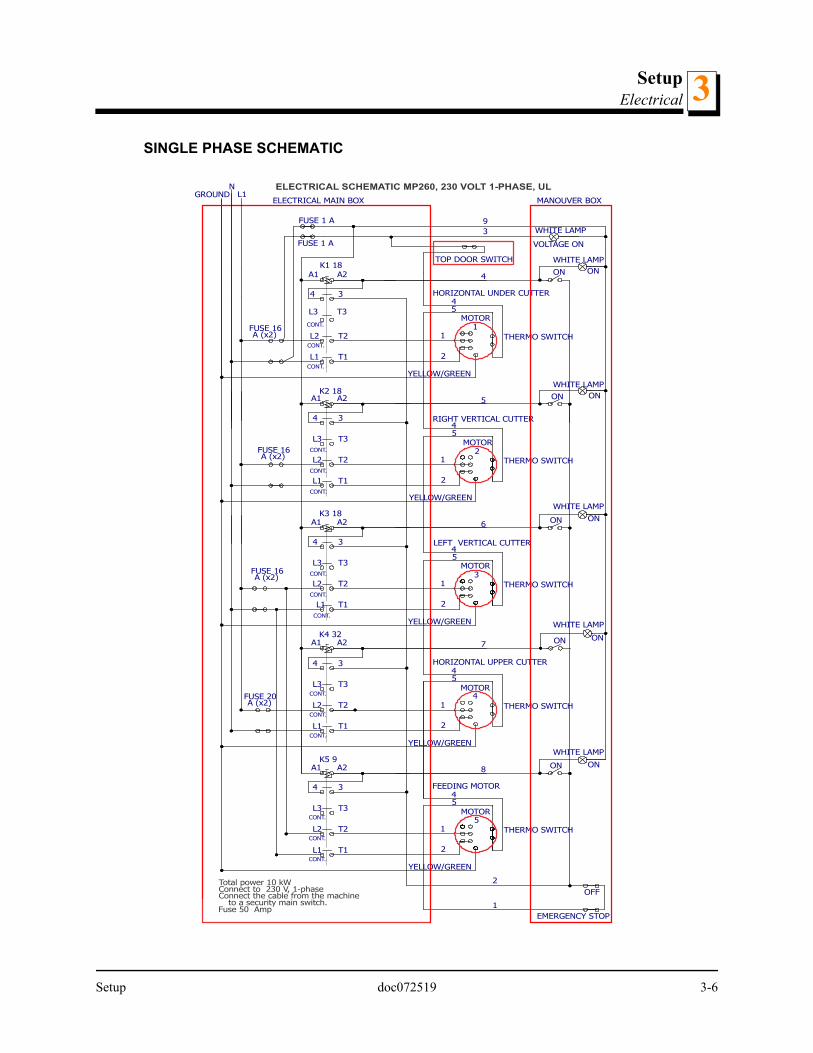
See Figure 3-10. The adjusting plates are held in place by countersunk screws.
The 2mm spacer is the most common setting.
NOTE: The spacer plates can be fitted in two ways. For normal plan-ing, fit the spacer so that the front plate edge is close to the lower cut-ter. This provides maximum support to the material while the lower cutter head is cutting it.
When profile knives are fitted to the lower cutter, the spacer is placed so that the tracks inthe planer table are visible. This allows longer knives, such as bottom relief knives usedfor making flooring, the ability to cut without impacting the spacer plate.
Various configurations used to remove wood:
4 mm (5/32”), do not use any takeoff adjustment plate. 3 mm (1/8”), use the 1 mm takeoff adjustment plate with beveled holes. 2 mm (5/64”), use the 2 mm takeoff adjustment plate. 1 mm (1/16”), use the 1 mm takeoff adjustment plate with flat holes (on the bottom)
AND the 2 mm takeoff adjustment plate.
FIG. 3-10
(Hidden)
No plate currently loaded: wood takeoff would be 5/32” (4mm).
Setup doc072519 3-18

SetupAdjusting upper cutter depth3
0 mm, use the 1 mm takeoff adjustment plate with beveled holes, the 1 mm takeoffadjustment plate with flat holes (sandwiched), and the 2 mm takeoff adjustmentplate.
Adjusting upper cutter depth
The cutting depth of the upper cutter is adjusted by turning the adjustment crank handlethat raises and lowers the cast iron table in the planer. Each turn of the crank raises orlowers the machine table 5/32” (4 mm).The scale on the front of the machine indicates thethickness of the finished material. The scale shows both metric and Imperial measure-ments.
By loosening the indicator screw and moving the indicator upwards or downwards, thescale can be calibrated to match the takeoff of the upper cutter.
See Figure 3-11.
The depth of cut is determined by the thickness of the rough board before it enters theplaner, less the amount of takeoff from the lower cutter, less the amount of the thicknessof the finished board.
FIG. 3-11
Scale
Adjustment handle
Scale Indicator
3-19 doc072519 Setup

SetupMoulding knives in upper and lower cutters 3
Examples:
Moulding knives in upper and lower cutters
Moulding knives can be mounted both in the lower and the upper cutter. The mouldingknives must always be mounted in pairs and in the same lateral position in the oppositeslots of the cutter head. A small degree of lateral deviation between the moulding knivescan be accepted, as long as the cutter head stays balanced.
The lower and the upper cutter have four knife slots each. As mentioned above, themachine comes with two mounted planing knives in each horizontal cutter. In the twoempty slots you can mount moulding knives of different sizes and profiles.
WARNING! Ensure the cutter head is balanced. Failure to follow this may result in serious injury or death.
IMPORTANT! If back relief knives are mounted in the lower cutter, these should be laterally positioned in such a way that they can pass through the tracks in the machine table.
IMPORTANT! Screwed to the chassis, above the machine table on the in-feed side, there is a limiting plate that, when it is turned up-side-down, limits the maximum takeoff of the upper cutter. This plate must be used when moulding knives are mounted in the upper cutter. If a work piece that is too thick is fed through the machine, the feed rollers can be pressed upwards so that they come in contact with the moulding knives.
1. Assemble the knife clamping gib and the moulder knife.
2. Insert the gib and the moulding knife in the wide end of the slot in the cutter head.
3. Push the knife and the gib along the slot, and then fasten them by turning the screw onthe back of the gib counterclockwise so that it presses against the side of the slot.
Imperial Metric
Rough lumber thickness 1-1/16 " Rough lumber thickness 26 mm
Takeoff of lower cutter 1/16" Takeoff of lower cutter 2 mm
Upper cutter head removes 1/8" Upper cutter head removes 3 mm
Resulting thickness 7/8" Resulting thickness 21 mm
Setup doc072519 3-20

SetupSide cutter setup3
IMPORTANT! The lock screw must be fixed in the narrow part of the slot. I must not be fixed in the wide end of the slot.
4. Measure the lateral position of the knife, and fit an identical knife in exactly the same posi-tion on the opposite side of the cutter head.
See Figure 3-12.
3.4 Side cutter setup
WARNING! Before adjusting the knives on this machine always turn off the electrical circuit supplying power to the machine. Failure to fol-low this may result in serious injury or death.
WARNING! Wear gloves when working with knives in the machine. Failure to follow this may result in serious injury or death.
CAUTION! Check for tools used in the operation and remove from the machine before closing the lid.
IMPORTANT! Check for free rotation of cutter heads before closing the lid.
FIG. 3-12
MMP002
3-21 doc072519 Setup

SetupSide cutter setup 3
TOOLS NEEDED:
12 mm open-end wrench. 30 mm open-end wrench (supplied). 4 mm hex key (supplied). Gloves.
SIDE CUTTER DESIGN
The side cutters have the following specifications:
Spindle Axle: Diameter 30 mm Cutting Height: Maximum 4" (100 mm) Rotation Speed: 7000 rpm Cutting Depth: Maximum 1 3/32" (28 mm)
Specifications of the side cutter heads shipped with the machine:
Diameter: Body 3 1/2" (90 mm) Height: Body 1 9/16" (40 mm) Planer Knives: HSS (High Speed Steel) Knives: Width 1 33/32" (50 mm)
See Figure 3-13. Anatomy of a side cutter head.
FIG. 3-13
Cutter head
Gib
Knife
Cutting edge
Direction of rotation
Setup doc072519 3-22

SetupSide cutter setup3
See Figure 3-14.
REMOVING RIGHT OR LEFT SIDE CUTTER
WARNING! Wear gloves when working with knives in the machine. Failure to follow this may result in serious injury or death.
See Figure 3-15. Location of the side cutters
FIG. 3-14
FIG. 3-15
Locking nut
Head
Spacers
Spacers (if needed)
Fixed side cutter head
Movable side cutter head
TOP VIEW
3-23 doc072519 Setup

SetupSide cutter setup 3
See Figure 3-16. Use the 30 mm and 12 mm open-end wrench in combination to loosenthe nut on the top of the shaft.
Loosen the nuts on the side cutters by screwing them in the same direction as theirrespective cutter rotate.
REPLACING KNIVES
1. Loosen the lock screw with a 4 mm hex key (supplied).
2. Remove the gib.
3. Remove the knife from the dowel pins.
4. Insert a new knife and gib.
5. Screw the lock screws tight.
IMPORTANT! Ensure the knives are mounted in the proper orienta-tions for the rotation of the head.
FIG. 3-16
NOTE: The lock nut and the spindle of the movable side cutter have left-hand threads.
Setup doc072519 3-24

SetupSide cutter setup3
See Figure 3-17.
Ensure that the chip deflector in front of the movable cutter does not get bent by theunplaned edge of the work piece coming in contact with the cutter. Be cautious process-ing work pieces of various widths.
Ensure that the cutter head can rotate freely, and that there is approximately 5 mm (0.2”)between the outermost cutting diameter of the cutter and the chip deflector that works asa chip barrier behind the movable cutter.
SETTING SIDE CUTTER KNIFE HEIGHT
Included with your planer is a package of shims/spacers of various thicknesses for theside cutter heads. These shims are packed in the parts box that is packed with yourplaner.
FIG. 3-17
Lock screw
Gib
Dowel pins
Rotation direction
3-25 doc072519 Setup

SetupSide cutter setup 3
See Figure 3-18.
Side cutter shims are used to raise the cutter head up and down on the cutter shaft. Usingshims allows the precise setting of the cutter head, and when locked in place, your settingwill not change. Also, shims provide you the ability to easily change your settings, as wellas the ability to return to specific settings, as long as you record the shims that are usedin that particular setup.
RAISING OR LOWERING THE CUTTER HEAD
Remove the cutter head and determine the amount of shims to place under the cutterhead to achieve the correct height of the head.
You may have to try several combinations of shims in order to achieve the correct heightsetting for the side cutter knives.
Replace the cutter in the same orientation as it came out.
IMPORTANT! Replaced the cutter heads back in the machine with the knives facing the correct direction. The leading edge of the knife should always turn into the wood. Ensure this knife is cutting into the wood when the head is rotating.
LOCK THE CUTTER HEAD IN POSITION
Place the large spacer rings above the cutter head. Only the treaded potion of the shaftshould be visible.
CAUTION! If the spacer rings are not stacked properly, the cutter head may spin on the shaft, causing the shaft to become scarred and dam-aged.
FIG. 3-18
40 mm Spacer20 mm Spacer10 mm Spacer5 mm SpacerSet of Spacers (0.1 - 2.0mm)
Setup doc072519 3-26

SetupSetting the movable side cutter head3
The top nut should then be replaced on the top of the shaft using two open-end wrenches– one to hold the shaft, and one to tighten the nut. (See figure 3-16.)
Setting the movable side cutter head
The movable side cutter head has a locking bolt under the table, on the output side anda locking screw accessed on the top of the table.
1. Loosen the movable side cutter locking bolt by the handle.
See Figure 3-19.
2. Use the crank on the front of the unit to move the side cutter in or out to the desired loca-tion to cut the left side of the board.
See Figure 3-20.
FIG. 3-19
FIG. 3-20
Movable cutter head locking bolt handle
OUTFEED VIEW
Movable cutter head adjustment handle
3-27 doc072519 Setup

SetupSetting the movable side cutter head 3
This initial setting will only be an approximation; for now, we are mainly setting the secondright side fence. Once this second right side fence is set, you will be able to accuratelymeasure the desired width.
SETTING THE LEFT SIDE PRESSURE ROLLERS
There are two pressure rollers on the infeed arm and one on the outfeed side of the mov-able cutter head. The pressure rollers hold the board against the side cutter fence.
The infeed pressure rollers are mounted on a bracket attached to the movable side cutter.It moves with the side cutter.
The pressure roller bracket fits into a groove just in front of the side cutter and can bemoved in or out as needed to allow for varying width boards. Where this bracket is placedalso determines the widest board the machine will accept. The pressure rollers should beset to approximately 1/8" less than the board width.
See Figure 3-21.
1. Set the pressure rollers by loosening the screw (6 mm hex key) that secures the rollerbracket on the movable cutter carriage.
2. Adjust the bracket so that the pressure rollers are pressed in approximately 0.2” (5 mm)when the work piece is fed into the machine. The pressure rollers do not need adjusting.
Behind the movable cutter there is an additional pressure roller, which presses the workpiece against the back fence.
FIG. 3-21
Setup doc072519 3-28

SetupFeed rollers3
3. Set the additional pressure roller so that it extends approximately 1/32 - 1/8” (1-3 mm)past the cutting diameter at the level of the pressure roller.
See Figure 3-22.
3.5 Feed rollers
The MP260 has five feed rollers, which feed the work pieces through the machine. Fourof these rollers are of ribbed metal and the last one has a rubber coating so that the sur-face of the work piece will not be marked when it exits the machine.
The feed rollers are run by a separate motor with a planetary gear. The rubber roller goesinto the planetary gear. On the rubber roller there is a sprocket, which drives the otherfour feed rollers via chain transmission.
Adjusting the feed roller pressure
On each end of the feeding rollers, there is a spring mounted bearing housing. Under thebearing housing there is a spring on a threaded bar. The pressure the feed rollers apply tothe work piece can be adjusted by turning the nut on the bottom of each threaded bar.Ensure the pressure is the same at both ends of the feed rollers.
Lubricate the bearing housings of the feed rollers with oil after each work session.
FIG. 3-22
MMP004
Adjustment bolt
1/32 - 1/8” (1-3 mm)
TOP VIEW
3-29 doc072519 Setup

SetupAdjusting the feeding speed 3
The rubber roller should also be adjusted so that it applies just the right pressure to thework piece. Remember that this feed roller should be set by the thickness the work piecehas when leaving the cutters.
IMPORTANT! Wood debris can accumulate under the feed roller spring mounted bearings. This impairs the feeding and increases the risk of the work piece being hurled out of the machine. Check these areas and, if necessary, remove the wood debris that has accumulated there.
Adjusting the feeding speed
The stepless feed speed can be adjusted by turning the knob on the planetary gear. If theknob is turned clockwise the feed speed is increased; if it is turned anticlockwise the feedspeed is lowered.
CAUTION! Do not adjust the feeding speed if the motor of the feed rollers is not running. Equipment damage may occur.
The optimum feeding speed varies depending on what sort of wood you are machining,the moisture content of the wood, and what type of moulding knives you have mounted inthe machine. The feeding speed can be adjusted from 2 m/min. to 12 m/min.
3.6 Leveling the machine table
IMPORTANT! Leveling the machine table is a complicated operation. Ensure that this operation is necessary before beginning any adjust-ments.
The machine table is already leveled from factory, but the table can have changed itsposition by rough handling during transport or by the machine being subject to impact.
INDICATIONS THAT THE MACHINE TABLE IS NOT LEVEL
The upper cutter cannot be adjusted so that it is parallel to the machine table The crank for raising and lowering the table is difficult or impossible to turn. The chain that connects the trapezoidal threaded bars that holds the machine table
has come off or has moved incorrectly on a sprocket.
Setup doc072519 3-30

SetupLeveling the machine table3
LEVELING THE MACHINE
1. Set the both bearing housings of the upper cutter in their lowest position. (See Initialsetup of upper cutter.)
2. Place an absolutely level block on the machine table directly head (not against the knivesor the knife slots).
3. Turn the machine table crank until the block comes very close to the cutter.
If it is impossible to raise the table, you need to take the measurement between the tableand the cutter head instead of using the block. This operation is slightly more difficult.
4. Loosen the chain for the machine table by opening the chain lock (take the opportunity toclean and lubricate the chain).
5. Turn each of the threaded bars until the cutter head touches the block along its entirelength (alternatively, measure between the table and the cutter head).
Each threaded bar has to be turned a little at a time to avoid the table getting locked dueto angular misalignment. Do not use force.
6. Check the table’s position lengthwise in the machine by measuring its height against theupper edge of machine frame, and level the table in this direction as well.
7. Ensure that all the threaded bars are easy to turn.
If a threaded bar is difficult to turn, it is due to angular misalignment of the table. Adjustthis by slightly turning the difficult bar, even if this results in the table being not completelylevel. This deviation is taken care of by fine-tuning the position of the upper cutter. (SeeInitial setup of upper cutter.)
8. Ensure that the table cannot be wobbled diagonally.
9. Place the chain on the sprockets and tension the chain using the chain tensioner on theout-feed side of the machine.
IMPORTANT! When the bearing housings of the upper cutter have been adjusted, or when the take-off of the planing knives has been altered, the rotating scale has to be calibrated. Possibly, the pointer on the height scale on the front side of the machine also has to be adjusted.
3-31 doc072519 Setup

SetupRunning the first test board 3
3.7 Running the first test board
WARNING! Check for tools used in the operation and remove from the machine before closing the lid. Failure to follow this may result in seri-ous injury or death.
IMPORTANT! Check for free rotation of cutter heads before closing the lid.
Use a board approximately 3 feet (1m) in length and uniform in dimension for the first runof the machine. In order to set the second right side cutter fence this board should bestopped before it runs completely through the machine. Specifically, the board should bestopped just in front of the pressure roller located just after the left side cutter.
See Figure 3-23.
1. Turn the machine on using the start button located on the control panel.
2. Start the cutter heads one at a time.
FIG. 3-23
Power AvailabilityIndicatorShown “On” (lighted)
Feed Motor On/Off
Power On/Off
Lower cutterOn/Off
Fixed side cutter On/Off
Movable side cutter On/Off
Upper cutter On/Off
Emergency Stop
Motor on/offindicators
Shown “Off” (notlighted)
Setup doc072519 3-32

SetupSide cutter fence setup3
3. Start the feed motor last.
A light above the start buttons should illuminate as the motors are started.
CAUTION! Do not adjust the feeding speed if the motor of the feed rollers is not running. Equipment damage may occur.
4. Slow the speed of the feed rollers down using he knob on the planetary gear. Turn theknob until you see the rollers slow down to their lowest speed.
5. Place the board on the infeed side of the table against the fence.
6. Slide the board into the machine, with the right side firmly against the fence, until you feelthe feed rollers begin to pull the board through the machine.
7. Watch the board feed through the planer through the observation window that is inte-grated into the lid.
8. Stop the machine with the stop button when the board gets just past the left side cutter,just before it comes in contact with the pressure roller next to the left side cutter.
Check the length of the fence. If needed, loosen the bolts holding the front of the fence tothe mounting brackets, sliding the fence to the correct position. Be sure and check rota-tion of the right cutter head before setting.
Side cutter fence setup
The right side cutter has two fences: the first and second side cutter fence. They are bothattached in similar fashion to the cast iron table.
3-33 doc072519 Setup

SetupSide cutter fence setup 3
See Figure 3-24. Here are their locations in the machine:
SETTING THE SECOND SIDE CUTTER FENCE
The second side cutter fence is located on the far side of the stationary cutter (see figure3-24). It is set back away from the path of the wood initially.
Pass a test board through the machine and then stop it in place.
Bring the second side cutter fence up to the wood and bolt it firmly against the wood.
FIG. 3-24
First side cutter fence Second side cutter fence
Setup doc072519 3-34

SetupSide cutter fence setup3
See Figure 3-25.
When your test boards are complete, and you are satisfied with your setup, you can beginrunning material through the machine.
FEEDING THE MACHINE
Ensure you have adequate room for the material that you will be putting in to and takingout of your planer. Your work area should be well lit, and clear of loose items on the floor,so there is little risk of tripping when handling long material. The paths to the infeed andoutfeed ends of the machine should be clear.
Material should be placed close to the infeed end of the machine for quick feeding into themachine and a stacking area should be prepared at the outfeed end.
Once the machine is started and boards are fed into the machine, it is recommended tokeep the material going through the machine one board after another, with the two boardstouching.
Place the straightest edge of the material against the right side fence. Ensure it is fed intothe machine with the edge against the first right side fence. Material that is fed into themachine at an angle will not straighten up in the machine and may cause problems withfences.
FIG. 3-25
Second side cutter fenceAdjustment bolts
3-35 doc072519 Setup

OperationOperation 4
SECTION 4 OPERATION
4.1 Operation
DANGER! Keep hands away from the knives. Failure to follow this willresult in serious injury or death.
DANGER! Do not operate the planer moulder without all covers andguards in place. Failure to follow this will result in serious injury ordeath.
WARNING! Do not operate the machine standing directly in front of theinput or output tables; kickbacks may occur. Failure to follow this willresult in serious injury or death.
WARNING! Minimum length of the work piece is 24” (600 mm). Do nottry to feed shorter pieces. Failure to follow this will result in seriousinjury or death.
Read and understand all information and warnings contained in theSafety section of this Operators Manual before starting theplaner.
CONTROL PANEL OPERATION
The MP260 is operated via the control panel located at the infeedend of the machine. The top right light on the control panel will illu-minate when power is being supplied to the machine. The bottomrow of buttons starts each motor independently of the others. Afteryou are certain the machine is correctly set up and clear of anytools or loose items, start only the motors you will be using.
NOTE: None of the motors will start if the planer’s observation/protec-tive lid is not securely closed, or if the Emergency Stop Button isdepressed.
The MP260 is equipped with a lid switch that must be engaged before the machine canbe started by the control panel buttons.
Operation doc072519 4-1

OperationOperation4
See Figure 4-1.
STARTING THE PLANER
IMPORTANT! Read and understand all information and warnings con-tained in the Safety section of this Operators Manual before startingthe planer.
NOTE: The best way to ensure that it is in the correct position is todepress the Emergency Stop Button in and then pull it out until youhere a click.
Check for rotation of all cutter heads before closing the lid and starting the machine. Eachcutter head should move freely and not impact any fences before starting.
Check that all tools used in the setup of the machine are removed from the machinebefore starting any of the motors.
The lid must be securely fastened down before the MP260 can be operated.
FIG. 4-1
Power AvailabilityIndicatorShown “On” (lighted)
Feed Motor On/Off
Power On/Off
Lower cutterOn/Off
Fixed side cutter On/Off
Movable side cutter On/Off
Upper cutter On/Off
Emergency Stop
Motor on/offindicators
Shown “Off” (notlighted)
4-2 doc072519 Operation

OperationPlaning tips 4
The Emergency Stop Button must be pulled out to allow motors to be started.
NOTE: The best way to ensure that it is in the correct position is todepress the Emergency Stop Button in and then pull it out until youhere a click.
STOPPING YOUR PLANER UNDER NORMAL OPERATING CONDITIONS
Under normal operating conditions, use the top left red button to stop the machine. Thisstops all motors at once. All of the motors can be restarted again after this stop button ispressed.
STOPPING YOUR PLANER IN AN EMERGENCY
The Emergency Stop button stops all motors. If an emergency occurs, and you need toquickly stop the machine, press the large red Emergency Stop button until you hear itclick. Once this button is pressed, the machine cannot be restarted until this button isturned 90° and pulled out to reset.
CAUTION! After every emergency stop wait at least 10 secondsbefore restarting the machine. If you do not wait, the fuse on the brakecard may blow or, if that fuse fails, you will damage the brake card.
4.2 Planing tips
General recommendations
If the knives in the upper cutter protrude too much, the last feed roller will not takehold of the workpiece. Recommended protrusion is 1 mm.
A planer/moulder is not a jointer; it only dimensions and moulds the workpiece. Forthis reason, the cutting parts in the machine should be as close to each other aspossible to avoid jointing operation. Paneling and other mouldings are normally notmachined in a jointer.
Keep the feed rollers clean from wood debris. The out-feed roller is especiallyimportant, since wood debris on this roller can make marks in the planed surface ofthe workpiece.
A certain degree of jointing operation is reached if the first feed roller is set so thatits pressure is somewhat lower than the pressure of the feed roller behind cutter 1.The board must then be positioned so that the convex side is turned upwards.
Be careful when adjusting the side fences. The back fence is to be level with theoutermost cutting diameter of the cutter. The two fences should be parallel with
Operation doc072519 4-3

OperationSizing stock4
each other and set so that the board is fed slightly diagonally (totally about 5 mmtowards the left) through the machine. By this the feed rollers will press the boardagainst the fences.
If you are going to produce a large amount of a moulding there is an additional lock-ing screw to secure cutter 3. The locking screw is recessed in a hole on the top ofthe carriage.
Use in- and out-feed tables. Ensure that they are mounted exactly at the sameheight as the machine table. Set the out-feed table so that it slants upwards a cou-ple of degrees. By this the board will be pressed down against the table whenreaching the last cutter, which reduces the risk of out-feed marks.
Reduce the air flow in the chip hose at cutter 2 when this cutter is to take off littlewood from the work piece. This will increase the air flow at the other cutters.
If you want to keep a roughly sawn surface on one side of the board, e.g. whenmaking outdoor siding that is to be painted, you let that side face the machine tableand do not start the lower cutter.
If you want to produce thinner three-sided mouldings than the machine is designedto make, you can place a flat board on the machine table which will make the work-piece come in a higher position in the machine.
The pressure springs of the feed rollers are to be set so that the feed rollers balanceon the workpiece. If the feed rollers lie diagonally over the workpiece they can pullaskew and, in addition, the grooves in the rollers will make deep marks in the work-piece. Balancing the feed rollers is extra important when thin workpieces aremachined. When changing from the 2-12 m/min. feeder to the 4-24 m/min. feeder,the pressure of the last feed roller has to be adjusted due to the weight of the plane-tary gear.
The chip extractor moves a large amount of air. If you blow the wood debris out of aheated room, the room will quickly become cold.
Sizing stock
This planer/moulder works best as a finishing planer/moulder. You can take rough lumberright out of the stack and plane it smooth. However, to achieve the best results with thismachine, it is best to have your stock as close to the size of the finished product as possi-ble. If you are planing with lumber that has a wide variance on thickness, it is best to runthis lumber through either this planer or another planer to size it to a uniform thicknessbefore finish planing and moulding it with this planer.
Some types of wood are prone to splintering. If you are taking too deep of a side cut, thewood can splinter and pull into the left side cutter. You can prevent this by reducing thedepth of cut that is taken off of that side of the stock.
4-4 doc072519 Operation

OperationPlaning narrow stock 4
For certain applications such as flooring, the lumber might need to have one side rippedto provide a straight edge. Your planer will not make a crooked board straight. If straightmaterial coming out of the planer is a requirement, then straight material will have to befed into the machine. Subjecting lumber to a straight-line rip will take the wane out of aboard. Place the ripped edge against the right side fence when feeding this ripped mate-rial through the machine.
Planing narrow stock
The MP260 can process very narrow stock. However, a motion-limiting block is posi-tioned in the machine between the two tubes that the left side vertical cutter head moveson. This limiting block is held in place by two bolts that are accessible underneath theblock. Take out the two bolts that hold the upper and lower halves of this block together,and remove the block.
Replace the motion-limiting block back into the machine when you are not planing narrowstock, as this block provides additional support to boards as they move through themachine, and across the width of the cast iron table.
Planing stock thicker than 2 Inches
The planer can mould and plane stock thicker than two inches with the side heads. Toaccomplish this two cutter heads must be stacked. When placing these cutter heads inthe machine, be sure to place the cutting knives on the second head halfway between thetwo knives on the first cutter head on that spindle.
Spacers can be used to add height to the upper cutter head; however, it is best if there issome overlap of the knives, especially with straight knives.
Cutter heads with a 4” height designed for this model can be ordered throughWood-Mizer.
Saving a moulding pattern
If you have produced a moulding that you know you will produce in the future, it can bewise to take some measures before removing the mounted knives. This will ensure thatyou can quickly set the machine for making the same moulding again.
1. Use a board that is approximately the same length as the moulder as your last run piece.
2. Stop the feed-in of this board as it is halfway through the cut.
3. Adjust the table and the moveable side cutter so that the board may be removed.
Operation doc072519 4-5

OperationTongue and groove4
4. Write down on the board the setting of the height scale of the table and the rotating scaleon the height adjusting crank, i.e. exactly note to what height the machine table is set.Also measure the machined moulding. Measure and note the spacers and the position ofprofile blades on the board.
Tongue and groove
When setting up this machine for tongue and groove material, start with several shortpieces of stock similar in size (width and thickness) to your finished product.
For tongue and groove that you have kept a sample from a previous run of this material,place the tongue and groove board from this previous run in the machine and match theknife height to match this original board.
1. Set the side cutters to the initial height by measuring with straight edges from the castiron table to the bottom of the groove.
2. Run a short test board through the planer.
3. Cut the test board in half and test the match.
4. To correct a mismatch, lay the two boards together on a flat surface. Slide a thicknessspacer ring(s) under the lower board until it is level. Use that spacer or combination ofspacers to level the cutting head.
4-6 doc072519 Operation

MaintenanceOverview 5
SECTION 5 MAINTENANCE
DANGER! Remove power before clearing debris or any other mainte-nance activity. Failure to follow this will result in serious injury or death.
Follow the OSHA lockout procedures reprinted in the safety section. (See LOCKOUT PROCEDURE in Safety.)
5.1 Overview
Your planer is a precision machine, and will provide you with professional results if kept ingood condition. Proper setup, alignment, cleaning, and lubrication are essential to thesuccessful operation of the machine. All knives must be kept sharp and uniform to ensurethe quality of cut and efficiency of operation. Operating your planer with dull knives willput undue stress on the machine, shortening its life.
5.2 Workspace
DANGER! Maintain a clean and clear path for all necessary movement around the planer moulder, tools, and material stacking areas. Failure to follow this will result in serious injury or death.
Having a clean and organized work area helps prevent most of the types of accidents that commonly occur in a workshop environment.
Your work space should have designated areas for tools, knives, shims, cleaning rags,scraps of material, or anything else that can either accidentally get placed/left in themachine. Constructing a tool board with designated spaces is an excellent way to alwaysknow where your planer tools and accessories are located. Locate you tool board closeby your planer. That way, before you start your machine, you can look at the tool boardand see if any tools are missing, and possibly left in your machine.
5.3 During use
Clean the machine from wood debris.
Ensure that wood debris has not accumulated under the machine. This can interfere withthe cooling of the motors and lead to a motor breakdown or, at worst, fire. Furthermore,the belt under cutter 4 can become slack if wood debris accumulates under its motor.
Ensure that all chip outlets are connected to the chip extractor.
Maintenance doc072519 5-1

MaintenanceAfter each use5
Ensure that all feed rollers can move.
The machine table should regularly be cleaned and treated with a lubricant, for examplelow-viscosity oil, silicon lubricants, or wax (3-1 oil, ChuteLube, silicon sprays, etc.).
5.4 After each use
1. Clean the machine from wood debris. Also check the chip outlets and the hoses. Removewood debris that has accumulated under the machine.
2. Clean the cutters and the feed rollers from resin and accumulated wood debris. Use min-eral spirits.
3. Ensure that wood debris has not accumulated behind the right side bearing housing ofthe upper cutter. If so, clean away the debris.
4. Ensure that wood debris has not accumulated in the springs under the bearing housingsof the feed rollers. If so, clean them. Sometimes the spring must be removed from thethreaded bar to be cleaned. Note the setting of the spring before removing it.
5. Clean the machine table and treat it with a lubricant (described above).
6. Clean and lubricate the three pressure rollers so that they can move easily.
7. Check belt tensions.
8. Make sure that all screws and bolts are tight.
9. Make sure that all cables and connections are in good condition.
10. Check the lamps by pressing down the emergency stop button and then the start buttonof the feeder.
IMPORTANT! Wood debris can accumulate under the spring mounted bearings of the feed rollers. This impairs the feeding and increases the risk of kickbacks.
5.5 Lubrication points
Ensure that following parts are well lubricated. Use a chain/gear oil with ISO ViscosityGrade 68.
5-2 doc072519 Maintenance

MaintenanceLubrication points 5
1. The bearing holders and springs of the feed rollers.
See Figure 5-1. Total of 10 - four steel rollers and one rubber
2. Lubricate the trapezoidal threaded bars.
See Figure 5-2. Located at all four corners
FIG. 5-1
FIG. 5-2
Maintenance doc072519 5-3

MaintenanceLubrication points5
3. Lubricate the chain and sprockets for height adjusting the table. Check the tension of thechain.)
See Figure 5-3. View from bottom, looking up; outfeed side; cover panel removed.
4. The carriage of the movable cutter.
See Figure 5-4. Lubricate position bars and the threaded rod.
If the movable cutter is set in the same position for a long time (e.g. when producing longseries of the same moulding) it can rust. Set the cutter so that it is in its outermost andinnermost position one or two times every month, and lubricate the threaded bar of thecrank and the position bars of the carriage.
FIG. 5-3
FIG. 5-4
5-4 doc072519 Maintenance

MaintenanceCleaning the metal feed rollers 5
5. The chain transmission of the feed rollers.
See Figure 5-5. Cover removed.
6. Knives, spacers, pressure rollers and side rollers.
See Figure 5-6.
5.6 Cleaning the metal feed rollers
Pitch may build up on the metal feed rollers if you are planing wood that has high resincontent.
FIG. 5-5
FIG. 5-6
Maintenance doc072519 5-5

MaintenanceTable lift assist chain adjustments5
1. Clean pitch buildup from the feed rollers with a soft wire brush (i.e. a brush with brassbristles) and some cleaning solvent to assist in loosening the pitch.
CAUTION! Do not spray/pour cleaning fluid directly on to the feed roll-ers. This may enter areas of the machine where it can cause damage or remove necessary lubricant.
2. Place the cleaning fluid on a high-nap cloth and wipe down the rollers with it.
3. Use a wire brush to assist in removing the pitch from the grooves on the roller.
4. When the rollers are completely clean, wipe them down again with a high nap cloth.
5. Finish by spraying a cloth with lubricant (high-quality silicone spray or WD-40) and wipingdown the rollers to prevent the future buildup of pitch.
DANGER! Dispose of cloths/rags used with flammable cleaning or lubricating fluid properly to avoid spontaneous combustion. Failure to follow this will result in serious injury or death.
IMPORTANT! If you are selling your shavings for livestock purposes, this may limit the type of cleaning fluid you can use for this purpose.
5.7 Table lift assist chain adjustments
The height of the cast iron table on your machine is adjusted by operating the removablecrank handle located on the infeed end of the machine. The crank handle is connected toa chain, which in turn is connected to the four threaded steel rods, which are threadedthrough the cast iron table. Eventually, through use, the chain will stretch slightly.
If this chain becomes stretched/slack, a sprocket (located at the bottom of the threadedrods) may skip a link during operation. When this occurs, the threaded rods will not besynchronized with each other and the cast iron table will not be level. Another way to sayit is that the “timing” of the four threaded rods is now out of synchronization, and the fourcorners of the cast iron table will not raise and lower at the same rate.
5-6 doc072519 Maintenance

MaintenanceTable lift assist chain adjustments 5
See Figure 5-7. Outfeed view, chain adjustment sprocket lock nut - use 17mm wrench
See Figure 5-8. View from bottom, looking up; outfeed side; cover panel removed.
1. Remove the cover panel by using a 5 mm hex key.
2. Loosen the sprocket nut by using a 17 mm wrench.
FIG. 5-7
FIG. 5-8
Maintenance doc072519 5-7

MaintenanceReplacing feed chain gear sprocket set screw5
3. Move the adjustment sprocket to take any slack out of the chain, and then retighten thesprocket nut.
5.8 Replacing feed chain gear sprocket set screw
The feed roller sprockets in the MP260 are equipped with set screws that are designed toshear off their heads if your planer gets in a bind. For example, if the size of the materialbeing fed into the machine is more than the machine can handle, the feed roller sprocketset screw will break off to protect the feed motor and drive train of the machine.
See Figure 5-9. Use a 4 mm hex key to remove set screws.
If sheared, remove these set screws and re-install new set screws in the feed rollersprocket.
1. Activate the feed mechanism until the set screw is opening downward.
2. Tap the front of the sprocket/gear with a piece of wood, causing the head of the shearedscrew to fall free.
3. Ensure the set screw hole is still aligned with the channel in the shaft.
NOTE: If the sprocket rotated on the shaft, it must be removed and re-aligned. Use a common automotive gear puller for this purpose. Ensure that you do not place the gear puller arms behind any of the sprocket/gear teeth, possibly bending or damaging them.
FIG. 5-9
Sprocket set screws
5-8 doc072519 Maintenance

MaintenanceRemoving and replacing feed chains 5
During the assembly process, a rust preventing varnish was applied to the feed sprocket and the feed roller shaft. Before replacing the feed sprocket, it is recommended that this varnish be removed to assist reassembly. Use emery cloth to lightly polish and remove the varnish that is on/around the shaft. Lightly polish and remove the varnish that is on the inside of the hole in the feed sprocket/gear. After this has been done, place the feed sprocket on the shaft. Pay close attention to lining up the set screw hole on the feed sprocket to the channel on the shaft.
4. Replace with a new set screw.
5.9 Removing and replacing feed chains
Each chain has a master link, which must be disassembled in order to remove the chain.The master links come from the factory facing outward, and they are easily recognizablebecause they look different from the rest of the links.
See Figure 5-10.
Remove the master link by placing a flat tip screwdriver behind the ends of the C-clip,apply pressure, and carefully push the C-clip off of its mounting points.
IMPORTANT! The C-clip is made from spring steel and can easily fly off, getting lost during the removal operation. Perform this operation in a clean, well-lit area.
FIG. 5-10
Master link
Maintenance doc072519 5-9

MaintenanceReplacing Belts5
5.10 Replacing Belts
The power to your machines vertical and horizontal cutters is transferred from electricmotors via multi-ribbed rubber belts. These belts will stretch and wear from a combinationof time and use, and may periodically require replacement.
Replacing stationary vertical cutter belt
1. Remove the collection hose and cover plate on the front of the MP260.
2. Loosen (do not remove) 4 cap head mounting screws holding the pulley of the stationaryvertical cutter. These screws pass through slots in the motor mount and fasten into thecast iron table.
See Figure 5-11. Use a 6 mm hex key to loosen mounting screws one turn
3. Use a 13mm open-end wrench to loosen the locking nut that secures the tension adjust-ing bolt in place.
4. Loosen (do not remove) the belt tension adjustment bolt to remove the tension from thedrive belt.
FIG. 5-11
Mounting screwsMotor mount
Motor
Motor pulley
Cutter pulley
Belt
5-10 doc072519 Maintenance

MaintenanceReplacing stationary vertical cutter belt 5
See Figure 5-12. Viewed from infeed side
5. Back out the tension adjusting bolt until the front of the bolt is flush with the front ofthe belt tension bolt bracket, but do not remove the bolt from the bracket.
6. From the front of the machine, pull the motor mount assembly towards you.
NOTE: The motor mount assembly’s movement towards you is limited to approximately ½ inch (13 mm) before the tension adjustment bolt bracket makes contact with the cast iron table.
NOTE: The belt must be finessed over the top of the drive (motor) pul-ley and under the bottom of the cutter pulley to come straight out. The clearances are tight but it will come out.
7. Replace the belt in the reverse order of how you removed it.
8. Ensure the belt is aligned on both pulleys.
9. Push the motor mount back until there is sufficient tension on the belt for operation.
10. Set the belt tension adjustment bolt to hold the tension.
11. Set the belt tension adjustment bolt locking nut to secure the adjustment bolt.
12. Retighten the 4 mounting screws holding the pulley of the stationary vertical cutter.
FIG. 5-12
Belt tension adjustment bolt
Belt tension adjustment boltlocking nut
Motor mount
Maintenance doc072519 5-11

MaintenanceReplacing movable vertical cutter belt5
13. Replace the cover plate and collection hose.
Replacing movable vertical cutter belt
This process is very similar to removing and replacing the stationary vertical cutter belt,but with a few minor differences related to the exterior parts of the machine you need toremove to gain access to the belt.
1. Remove the movable vertical cutter chip extractor hose mount.
See Figure 5-13.
2. Remove rear cover of the movable vertical cutter. The chip extractor hose mount andhose will come off with the cover.
3. Remove the outfeed side panel.
The remaining steps in this process are the same as those explained in the section“Replacing stationary vertical cutter belt” on page 10.
FIG. 5-13
Remove hose mount screws
5-12 doc072519 Maintenance

MaintenanceReplacing movable vertical cutter belt 5
See Figure 5-14. Use a 6 mm hex key to loosen mounting screws one turn
4. Loosen (do not remove) 4 cap head mounting screws holding the pulley of the stationaryvertical cutter. These screws pass through slots in the motor mount and fasten into thecast iron table.
5. Loosen (do not remove) the belt tension adjustment bolt to remove the tension from thedrive belt.
NOTE: The belt tension adjustment bolt on the movable vertical cutter is accessible from the top of the machine.
See Figure 5-15. Viewed from top of unit
FIG. 5-14
FIG. 5-15
Mounting screws
Motor pulley
Cutter pulley
Belt
Belt tension adjustment bolt
Belt tension adjustment boltlocking nut
Maintenance doc072519 5-13

MaintenanceSharpening Knives5
6. Use a 13mm open-end wrench to loosen the locking nut that secures the tension adjust-ing bolt in place.
7. Back out the tension adjusting bolt until the front of the bolt is flush with the front ofthe belt tension bolt bracket, but do not remove the bolt from the bracket.
8. From the front of the machine, pull the motor mount assembly towards you.
NOTE: The motor mount assembly’s movement towards you is limited to approximately ½ inch (13 mm) before the tension adjustment bolt bracket makes contact with the cast iron table.
NOTE: The belt must be finessed over the top of the drive (motor) pul-ley and under the bottom of the cutter pulley to come straight out. The clearances are tight but it will come out.
9. Replace the belt in the reverse order of how you removed it.
10. Ensure the belt is aligned on both pulleys.
11. Push the motor mount back until there is sufficient tension on the belt for operation.
12. Set the belt tension adjustment bolt to hold the tension.
13. Set the belt tension adjustment bolt locking nut to secure the adjustment bolt.
14. Retighten the 4 mounting screws holding the pulley of the vertical cutter.
15. Replace the cover plate and collection hose mount.
5.11 Sharpening Knives
The condition of your machine’s knives will affect the quality and precision of the cut. Payclose attention to the quality of the cut to get an idea about the condition of the machine’sknives. Dull knives will tear, not cut the wood fibers, producing a fuzzy appearance on thewood. A raised ridge (or ridges) running along the length of a wood plank can occur whena nicked knife impacts the wood.
On planer knives and moulding knives, it is possible to bring the knives back to a sharpcondition by sharpening the face of the knife. Running a diamond stone against theface will bring knives back to a sharp condition. This can be done about 3 times beforethe knives will need to be sharpened by a sharpening machine.
5-14 doc072519 Maintenance

MaintenanceSharpening Knives 5
If a raised ridge occurs the entire length of the plank that you are processing, then theknife/knives have been nicked. Sharpened the knife/knives to remove the nick.
Knives that are not sufficiently sharp will heat up when cutting. If you see blackenededges on moulding knives, this is an indication that the knives are not sharp. Continuingto use these knives will cause excessive wear on the machine, and will further degradethe knives themselves. Remove and sharpen the knives.
NOTE: The speed of the material that is being fed through the machine can have an affect on knife life. Ideally, with each revolution of the cut-ting head, the planer knife should be removing new material. The new material will absorb a portion of the heat created by the knife cutting the wood, and will cool the knife as it is cut away. However, if the knife is not cutting new material each time the cutting head makes a revolu-tion, the friction created will cause the knife to heat up. Excessive heat will dull your machines knives, and shorten their life.
Utilizing a test board, set the feeding speed of the machine so that chatter marks becomevisible, and then reduce the speed until a smooth finish is seen. This method will ensurethat the knives are cutting new wood on each revolution. The optimal feeding speed willvary between the type of wood being processed, and the type of moulding knives beingused.
Maintenance doc072519 5-15

TroubleshootingOperation problems6
SECTION 6 TROUBLESHOOTING
DANGER! Remove power before clearing debris or any other mainte-nance activity. Failure to follow this will result in serious injury or death.
Follow the OSHA lockout procedures reprinted in the safety section. (See LOCKOUT PROCEDURE in Safety.)
DANGER! Keep hands away from the knives. Failure to follow this will result in serious injury or death.
DANGER! Do not operate the planer moulder without all covers and guards in place. Failure to follow this will result in serious injury or death.
6.1 Operation problems
Problem Possible Cause Remedy
In-and out-feed marks. 1. Incorrectly adjusted in- and out-feed tables.
2. The workpieces are not butted when being fed into the machine.
3. The feeding pressure of the feed rollers is incorrectly adjusted.
4. The workpiece is bent or warped.
5. There is play in the suspension of the machine table.
1. Adjust the in- and out-feed tables so that they are set to the same height as the machine table. The tables must also be in line with the machine table or somewhat higher at the outer ends.
2. Butt the workpieces end to end when feeding them into the machine. This will eliminate the variations of the feeding pressure that can occur the moment the feed rollers grab the workpiece.
3. Make sure that the feeding pressure is sufficient and that the rollers are bal-ancing horizontally over the workpiece.
4. Slightly lift the back end of the work-piece when it is being fed into the machine. This will make it possible for the feed rollers to press the workpiece flat against the machine table.
5. By using little force, check if the machine table can be wobbled in any direction. If this is the case, see Leveling the machine.
6-1 doc072519 Troubleshooting

TroubleshootingOperation problems 6
The entire surface is fuzzy. 1. The workpiece has high moisturecontent.
2. The knives have lost theirsharpness.
1. Dry the timber before machining it.
2. Grind the knives. It is especially important that the knives are sharp when soft or moist wood is being machined.
Fuzzy surface around knots, where the direction of the fibers can vary.
1. The workpiece has high moisture content.
2. The knives have lost their sharp-ness.
3. The workpiece is of a too soft sort of wood.
1. Dry the timber before machining it.
2. Grind the knives. It is especially important that the knives are sharp when soft or moist wood is being machined.
3. Choose another material, or sand the workpiece after it has been machined.
The thickness of the board does not correspond to the setting of the scale.
1. The takeoff of the knives in the upper cutter are set incorrectly.
2. The pointer of the height scale is set incorrectly.
1. Set the takeoff of the planing knivesto 1 mm, using the setting block sup-plied, or a straightedge.
2. Machine a test board, measure it and set the pointer to this measurement. Fine-tuning of measurements should always be done using the rotating scale of the height-adjusting crank, which can easily be reset. The scale shows 1 mm every quarter of a turn.
The edges of the molding knives are visible in the machined moulding profile.
1. The planing knives do not cut away enough wood.
2. The moulding knives are ground incorrectly
1. Set the takeoff of the planing knives to 1 mm, using the setting block supplied, or a straightedge.
2. Regrind the moulding knives so that their edges do not protrude over the level of the planing knives, or use adjust-able, short knife clamping gibs to adjust the moulding knives correctly.
Problem Possible Cause Remedy
Troubleshooting doc072519 6-2

TroubleshootingOperation problems6
The width of the machined board differs.
1. The workpiece moves away from the side fences.
2. The locking handle of the mov-able cutter has not been tightened.
3. The pressure rollers are set incor-rectly.
4. The spring mechanism of the pressure rollers is stiff.
5. The workpiece is too small for the measurement the machine is set to.
6. The stationary side cutter cuts away too much wood.
1. The right-side fences are set incor-rectly. Adjust them according to the instructions.
2. Pull the handle tight before planing/ moulding.
3. Adjust the L bracket on which the first two pressure rollers are mounted and also adjust the pressure roller behind cutter 3. 4. Clean and lubricate the spring mecha-nisms of the three pressure rollers.
5. Choose a wider workpiece or set the machine to less width.
6. Decrease the feeding speed or the takeoff of the stationary cutter.
The surface of the workpiece’s right side is below par.
1. The locking handle of the mov-able side cutter has not been tight-ened.
Pull the handle tight before planing/ moulding.
Splinters are being battered out of the workpiece when it reaches the movable side cut-ter.
1. Too much takeoff.
2. The chip deflector is incorrectly mounted.
1. Plane the workpiece into size before the final machining.
2. Mount the chip deflector so that it presses against the workpiece in front of the cutter.
Problem Possible Cause Remedy
6-3 doc072519 Troubleshooting

TroubleshootingMechanical or electrical problems 6
6.2 Mechanical or electrical problems
Problem Possible Cause Remedy
None of the motors can be started.
1. The cover is not entirely closed. 2. The emergency stop button is pressed down.
3. No power is supplied to the machine.
4. One of the motors is overheated.
5. Fault in the electrical system of the machine.
6. A fuse has blown in the electric box of the machine.
7. Wood debris has accumulated in the cover’s safety switch.
1. Firmly tighten the locking knob on the cover. You can hear a soft click when the safety switch is activated.
2. Reset the emergency stop button by pulling it outwards.
3. Check the residual circuit breaker and the fuses in the building. Also check the connecting cable.
4. Wait until the overheating protection of the motor automatically resets (see the point, “The motor gets overheated.”).
5. The electrical system may only be opened by a qualified electrician: First of all, check the safety hold circuit. This cir-cuit includes, among other things, the emergency stop button and the over-heating protections in the connection block on each motor.
6. The machine has one or two auto-matic fuses. Reset the fuse that has blown. If the problem recurs, let a quali-fied electrician find the cause of the problem and, if necessary, replace the fuse.
7. The electrical system may only be opened by a qualified electrician: Open and clean the safety switch from wood debris.
Troubleshooting doc072519 6-4

TroubleshootingMechanical or electrical problems6
The workpiece is fed poorly or not at all through the machine.
1. The shear pin in the out-feed roller is broken.
2. Wood debris and resin have accumulated in the grooves of the feed rollers and on the out-feed roller.
3. The pressure of the feed rollers is too low.
4. The vertical movement of the feed rollers is obstructed by wood debris that has got stuck in the verti-cally movable bearing housings of the feed rollers or in the springs under these.
5. Wood debris has accumulated around the upper cutter.
6. The machine table is covered with resin or rust.
7. The sliding strips under the feed rollers are defect.
8. One (or several) of the sprockets in the chain transmission of the feeder has come loose from the shaft.
1. Remove the planetary gear and replace the broken shear pin.
2. Clean the feed rollers.
3. Increase the feeding pressure and make sure the feed rollers are balancing horizontally over the workpiece.
4. Clean the bearing housings of the feed rollers, especially check the mov-able part of the bearing housing. Remove wood debris that has got stuck in the springs of the feed rollers.
5. Remove the wood debris and increase the air flow in the chip extractor of the upper cutter.
6. Clean and lubricate the table.
7. Replace the sliding strips and fasten the new ones with double coated tape, if necessary in several layers, so that the the sliding strips are about 0.5 mm above the surface of the machine table.
8. Check the locking screws of the sprockets and tighten them against the flat part of the shaft.
The upper cutter rotates a long time after the machine has been shut off (the deceleration should be max. 10 seconds).
1. The fuse on the brake card has blown.
2. The brake card is defect.
1. Replace the glass fuse on the card.
2. Replace the defect brake card. On the new brake card there is a potentiometer that has to be adjusted (about 1/4 turn from 0).
One of the motors will not start. 1. Defect contact.
2. Defect motor.
3. A cable to the contact or to the motor is loose.
1. The electrical system may only be opened by a qualified electrician: Replace the defect contact.
2. The electrical system may only be opened by a qualified electrician: Replace the defect motor.
3. The electrical system may only be opened by a qualified electrician: Ensure that all cables are correctly connected.
Problem Possible Cause Remedy
6-5 doc072519 Troubleshooting

TroubleshootingMechanical or electrical problems 6
The workpiece is fed jerkily through the machine.
1. The machine table is covered with resin or rust.
2. One of the feed rollers has been bent.
1. Clean and lubricate the table.
2. Replace the bent feed roller.
The machine runs for a while but then stops.
1. One of the motors, in most cases the motor of the upper cutter, gets overheated.
1. See the next point, ‘‘The motor gets overheated.”
The motor gets overheated. 1. Wood debris has accumulated in the chassis of the machine or around the cooling fans of the motors.
2. Dull knives.
3. Too low voltage in the power sup-ply.
4. Loose or bad connection in the power supply to the machine or in the electrical system of the machine.
5. The upper cutter removes too much wood.
6. The feeding speed is too high.
1. Make sure that wood debris has not accumulated in the machine, and that the cooling fans of the motors have free flow. If the motors are kept clean they will be cooled more efficiently.
2. Grind or replace the knives.
3. The electrical system may only be opened by a qualified electrician: Check that you have the correct voltage on all phases.
4. The electrical system may only be opened by a qualified electrician: First of all, check that the connecting cable has the correct current and voltage during operation. Also check that all wires are correctly connected in the electrical sys-tem and motors of the machine.
5. If the workpiece is to wide, of a hard sort of wood or of varying oversizes: plane it into size before the final machin-ing.
6. Decrease the feeding speed.
Play in the adjusting crank of the movable side cutter.
1. The bronze bearing in the bearing housing of the crank is defect. One reason for this can be that the crank has been turned when the locking handle of the carriage is tightened.
1. Replace the bronze bearing and remember to open the locking handle under the table before adjusting the side cutter.
Problem Possible Cause Remedy
Troubleshooting doc072519 6-6

TroubleshootingMechanical or electrical problems6
Vibration or rumble in the side cutter.
1. The moulding knives are incor-rectly mounted.
2. The moulding knives are incor-rectly ground.
3. Defect bearing.
4. The spindle shaft has been bent due to overloading.
5. The belt transmission is defect.
1. Demount the cutter head, and clean and mount the knives and the chip breakers correctly. Identical knives should be mounted on opposite sides of the cutter.
2. Grind the knives in pairs so that they are identical on the opposite sides of the cutter.
3. Replace the bearing.
4. Replace the spindle shaft.
5. Clean the belt pulleys and replace the Poly V belt.
Rumbling or vibration in the upper or the lower cutter.
1. The moulding knives are incor-rectly mounted.
2. The moulding knives or the plan-ing knives are incorrectly ground.
3. The bearing is defect. This can be due to wood debris that has accu-mulated on the back of the bearing housing, which leads to overheat-ing.
4. The belt transmission is defect.
1. Clean the cutter and mount the knives and the chip breakers correctly. Identical knives should be mounted on opposite sides of the cutter without any, or with only slightly horizontal deviation.
2. Grind the knives in pairs so that they are identical on opposite sides of the cutter.
3. Clean the bearing housing and replace the ball bearing.
4. Clean the belt pulleys and replace the Poly V belt.
It is difficult to adjust the height of the machine table.
1. The trapezoidal thread bars, on hich the table is suspended, are dirty and not lubricated.
2. Faulty chain transmission.
3. The machine has been subject to impact which has spoiled the setting of the table.
1. Clean and lubricate the trapezoidal thread bars with oil.
2. Make sure that the chain runs cor-rectly on the sprockets. Clean and lubri-cate the chain.
3. Adjust the table. (See Leveling the machine of Setup)
Problem Possible Cause Remedy
6-7 doc072519 Troubleshooting

PartsHow To Use The Parts List 7
SECTION 7 PARTS
7.1 How To Use The Parts List
To Order Parts
From the continental US, call 1-800-525-8100 to order parts. Have your customernumber, machine serial number, and part reference numbers ready when you call.
From other international locations, contact the Wood-Mizer distributor in your areafor parts.
7.2 Sample Assembly
The Assemblies may contain more than one part.
REF DESCRIPTION QTY
1 SAMPLE PART 1
SAMPLE ASSEMBLY INCLUDES ALL INDENTED PARTS BELOW 1
3 Subassembly Sample Part 1
4 Subassembly Sample Part 1
Parts doc072519 7-1

PartsPart Location7
7.3 Part Location
6 7 9 3 10 11123 13
32
203334
36
37
1819202122
24
2526
28
29
38
39 40
2741
35
70
1 2
23 71
72
24
23
14
30
83 4 15
17
16
31
63
MMP005
7-2 doc072519 Parts

PartsPart Location 7
REF DESCRIPTION QTY
1 CRANK FOR MACHINE TABLE, COMPLETE ASSEMBLY 1
2 PROTECTIVE PLATE, IN-FEED 1
Feed roller, grooved, 2 long pieces, 2 short pieces 4
Bearing seat, complete 10
3 BEARING HOLDER 10
4 SWITCH INFEED SECURITY 1
5 SWITCH, COVER 1
6 COVER 1
Window 1
Handle 1
7 CUTTER 2
Vertical cutter spindle, right thread 1
Spindle nut, right thread 1
MMP0006
43 44 45 46 47 48
16
14
18
12
49
20
38
5051526162 5556
63
65666768
69
5354
5
58 57 425960
68 64
Parts doc072519 7-3

PartsPart Location7
Set of spacers 1
Universal cutter 1
Upper track bearing 1
Lower track bearing 1
Track ring, sga 30 1
8 LOCKING HANDLE 1
9 CHIP DEFLECTOR, CUTTER, LEFT AND RIGHT 2
10 CARRIAGE, CUTTER 1
11 CUTTER 1
Vertical cutter spindle, left thread 1
Spindle nut, right thread 1
Set of spacers 1
Universal cutter 1
Upper track bearing 1
Lower track bearing 1
Track ring, sga 30 1
12 CARRIAGE SHAFT 2
13 CHIP HOOD 1
14 UPPER HORIZONTAL CUTTER, 410 1
Planing knife, 410 1
Chip breaker, 410 1
Bearing 1
15 FEED ROLLER, RUBBER, PH 1
16 BEARING SEAT, COMPL FOR FEEDING ROLLER. 1
17 PROTECTIVE PLATE, EXIT 1
18 BEARING BRACKET 1
19 TRAPEZOIDAL THREAD BAR 1
20 TABLE 1
Plastic runners 4
21 CARRIAGE LOCKING HANDLE 1
22 BELT GEAR HOUSING, CUTTER 2 AND 3 2
23 BELT GEAR, CUTTER 2 AND 3 2
Poly V belt pulley, motor 2
Poly V belt pulley, spindle 2
Poly V belt 2
24 ELECTRIC MOTOR, CUTTER 2 AND 3 2
25 LOWER BEARING WASHER 4
Bronze bushing 4
Chain sprocket, trapezoidal 4
Thread bar 3
Chain lock 1
Chain, table 1
REF DESCRIPTION QTY
7-4 doc072519 Parts

PartsPart Location 7
26 CHAIN WHEEL FOR THREAD BAR 4
27 CHAIN FOR THREAD BAR, TABLE 1
28 ELECTRIC MOTOR, UPPER HORIZ. CUTTER 1
29 MOTOR SUPPORT 1
30 CONTROL PANEL 1
Control box 1
Control box cover lid 1
Emergency stop 1
Control button, ON, white 5
Lamp holder with cap 5
31 CONTROL BOX BRACKET 1
32 TRAPEZOIDAL THREAD BAR WITH CRANK 1
33 BEARING BRACKET LOWER CUTTER 1
34 LOWER HORIZONTAL CUTTER, 300 1
Planing knife, 300 2
Chip breaker, 300 2
Bearing 1
35 CHIP OUTLET, LOWER HORIZONTAL CUTTER 1
36 MOTOR SUPPORT BRACKET 1
Motor support 1
37 ELECTRIC MOTOR, LOWER HORIZ. CUTTER 1
38 FRAME 1
39 UPPER BEARING WASHER, CRANK 1
40 UPPER BEARING WASHER 3
41 CHAIN TENSIONER, COMPLETE 1
42 CRANK FOR CARRIAGE, CUTTER 3 1
Threaded bar, carriage, cutter 3 1
43 CHIP OUTLET, CUTTER 3 1
44 HOSE CLAMP 2
45 INNER CHIP OUTLET, CUTTER 3 1
46 PRESSURE ROLLER 1
47 COVER FOR BELT DRIVE 1
48 BELT PULLEY, UPPER HORIZONTAL CUTTER 1
49 SUPPORT, CARRIAGE OPENING 1
50 WORM GEAR, MOTOR 1
Strut, feeder motor 1
51 FEED CHAIN 4 1
52 FEED CHAIN SPROCKET 8
53 FEED CHAIN 3 1
54 FENCE 2 1
55 FENCE BRACKET 1
56 FENCE AXLE 1
REF DESCRIPTION QTY
Parts doc072519 7-5

PartsPart Location7
57 COVER FOR FEED ROLLER CHAIN 1
58 CHIP CHANNEL, CUTTER 2 1
59 FEED CHAIN 2 1
60 CHIP DEFLECTOR, CUTTER 2 1
61 FEED CHAIN 1 1
62 FENCE 1 1
63 POINTER, HEIGHT ADJUSTMENT SCALE 1
Scale 1
64 L BRACKET 1
65 FLEXI HOSE, CUTTER 3 1
66 BRACKET 1
67 ELECTRIC BOX 1
68 SIDE ROLLER 1
69 ADJUSTING PLATE 1 MM, TOP 1
Adjusting plate 1 mm 1
Adjusting plate 2 mm 1
70 70 BELT GEAR, LOWER CUTTER 1
Poly V belt pulley, motor 1
Poly V belt pulley, spindle 1
Poly V belt 1
71 SCREW FOR BELT TENSIONING 1
72 SCREW FOR LOCKING THE BELT TENSION 1
REF DESCRIPTION QTY
7-6 doc072519 Parts