Embed Size (px)
Citation preview
Publication 245-EN – November 2013
Setup and Operating Instructions
MP15 Jockey Pump Controller
This manual provides general information, installation, operation, maintenance,
and system setup information for Metron Model MP15 Jockey Pump
Controllers.
Section Page
Introduction 2
Installation 3
Operation of the Controller 5
Operator Interface Device (OID) Use and Navigation 7
System Set Point Definitions 12
Test Procedure 14
Alarm and Event Log Messages 15
Disposal 16
Replacement Parts & Technical Support 17

2 MP15 Jockey Pump Controller
Publication 245-EN – November 2013
Introduction Metron MP15 Jockey Pump Controllers are microprocessor based controllers
intended for use with the main fire pump system. The jockey pump's purpose is
to help maintain normal water pressure and prevent unnecessary cycling of the
main fire pump(s).
Approvals
Metron MP15 controllers are listed by Underwriter's Laboratories, Inc., in
accordance with UL508A, Standard for Industrial Controls; and CSA, Standard
for Industrial Control Equipment (cUL).
NOTICE Read these instructions thoroughly before
installing and operating the controller. If there
are still questions, contact your Metron factory
representative for assistance.

MP15 Jockey Pump Controller 3
Publication 245-EN – November 2013
Installation The controller has been assembled and wired at the factory with the highest
workmanship standards. All wiring and functions have been thoroughly tested to
ensure correct operation when properly installed.
Receiving, Handling, and Storage
1. Immediately upon receipt, carefully unpack and inspect the controller
for damage that may have occurred in shipment. If damage or rough
handling is evident, file a damage claim with the transportation carrier
immediately.
2. If the controller must be stored, cover it and then place it in a clean, dry
location. Avoid unheated locations, where condensation can result in
damage to the insulation or corrosion of metal parts.
Precautions
CAUTION To avoid risk of SERIOUS INJURY or DEATH, and to
avoid damage to the controller, READ THIS SECTION
CAREFULLY. If questions or concerns still exist,
contact the Metron factory for further
clarification.
If work must be carried out on the motor or controller, ensure the controller is
ISOLATED AND LOCKED OFF from the AC mains supply before work
commences. Lockout/Tag out procedures should be followed in accordance
with OSHA standard and any local standards that may apply.
During installation and maintenance, to prevent automatic starting of the motor
ensure the controller HOA Switch is in the Off position.
To avoid risk of serious electric shock, never energize the controller with the
access door open unless absolutely necessary.
If the access door to the interior of the panel has to be opened when the panel is
energized, take caution that high voltage is present.
Installation Instructions
Mounting The controller should be mounted using appropriate fixing methods:

4 MP15 Jockey Pump Controller
Publication 245-EN – November 2013
A. If the controller is mounted directly to the pump skid, anti-vibration
mounts should be used.
B. If the controller is mounted to a wall, it should use the four (4) external
mounting holes of the controller cabinet. Suitable fixings to the wall
should be used taking into consideration the weight of the controller. It
is recommended that the controller be mounted at least 12 inches
(300mm) above floor level.
Electrical Connections
DANGER
SHOCK HAZARD
Electric shock may result in SERIOUS INJURY
OR DEATH. Electrical connections should be
made by a qualified electrical engineer only.
Refer to Field Connection drawing supplied with the controller.
The installer is responsible for ensuring no metallic foreign objects
(such as drilling chips, etc.) fall inside the controller onto the electrical
circuit. Failure to observe this could result in damage to the controller
and will void the controller warranty.
The cabinet should be properly grounded per the requirements of
NFPA 70.
NOTE: It is highly recommended, although not essential, that the
following recommendations are considered:
o All signal wiring should be separated from power feeds and
supplies. Where the two must be in close proximity, it is
advisable that they are located at right angles to each other.
o Signal wiring will be less prone to disturbances if contained
within grounded conductive conduit or trunking. Avoid
passing signal cables in close proximity of known interference
sources, or high power electrical equipment where possible.
o Refer to the Field Connection diagram for wiring sizes.
MP15 Jockey Pump Controller 5
Publication 245-EN – November 2013
Operation of the Controller
General Information
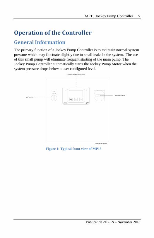
The primary function of a Jockey Pump Controller is to maintain normal system
pressure which may fluctuate slightly due to small leaks in the system. The use
of this small pump will eliminate frequent starting of the main pump. The
Jockey Pump Controller automatically starts the Jockey Pump Motor when the
system pressure drops below a user configured level.
1 2 3
Drawing not to scale
HOA Selector
OFF
HAND AUTO
Operator Interface Device (OID)
Disconnect Switch
Figure 1: Typical front view of MP15

6 MP15 Jockey Pump Controller
Publication 245-EN – November 2013
Functions
Disconnect switch - Controls jockey pump main power. Can be
padlocked in the "OFF" position.
Operator Interface Device (OID) — Provides visual indication of
system pressure, alarms, events, and system messages.
Hand-Off-Auto (HOA) Selector switch.
o Hand - Manually starts the jockey pump.
o Off - Manually stops the jockey pump.
o Auto - Jockey pump starts and stops automatically.
USB port for recording alarm and event data log records to a USB
memory stick.
Sequence of Operation
The explanation of the Sequence of Operation will start with the assumption that
the controller has been properly installed, all external connections have been
made, and the Motor Starter Protector is closed.
Manual Operation To manually start the jockey pump motor, turn the HOA Selector to the Hand
position. This will cause the Motor Contactor contact to close, thus starting the
motor.
To manually stop the motor, turn the HOA Selector to the Off position, thus
causing the Motor Contactor contact to open.
Automatic Operation For automatic operation of the jockey pump motor, turn the HOA Selector to the
Auto position. When the system pressure drops below the user configured Start Pressure, the Motor Contactor contact will close, thus starting the motor.
The controller will automatically open the Motor Contactor contact once the
system pressure rises to or above the user configured Stop Pressure, and the
Minimum Run Timer is either disabled or expired.

MP15 Jockey Pump Controller 7
Publication 245-EN – November 2013
Operator Interface Device (OID) Use and Navigation The Operator Interface Device (OID) provides visual indication of the alarms,
status of system parameters, and an interface for adjusting set points to
configure the MP15.
Using the OID Controls
There are three types of windows displayed on screen:
Informational, such as the home window.
Menus, which navigate to a sub-list of windows. They are denoted
onscreen with an arrow to the right of the text.
Set Points, which display the set point name and its current value.
Use the E N T E R , U P , and D O W N buttons to navigate through onscreen menus,
change set points, and view system information.
To Do this
Go to the next window Press the D O W N button.
Go to the previous window Press the U P button.
Choose a menu item Press the E N T E R button.
Go back to the previous menu Press the U P and D O W N buttons
simultaneously.
1 2 3
Power AvailableLED
Pump RunningLED
Enter Button
Up Button
Down Button
Drawing not to scale
Figure 2: Operator Interface Device (OID)
8 MP15 Jockey Pump Controller
Publication 245-EN – November 2013
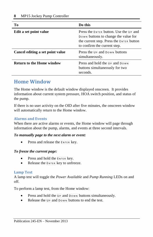
To Do this
Edit a set point value Press the E N T E R button. Use the U P and
D O W N buttons to change the value for
the current step. Press the E N T E R button
to confirm the current step.
Cancel editing a set point value Press the U P and D O W N buttons
simultaneously.
Return to the Home window Press and hold the U P and D O W N
buttons simultaneously for two
seconds.
Home Window
The Home window is the default window displayed onscreen. It provides
information about current system pressure, HOA switch position, and status of
the pump.
If there is no user activity on the OID after five minutes, the onscreen window
will automatically return to the Home window.
Alarms and Events When there are active alarms or events, the Home window will page through
information about the pump, alarms, and events at three second intervals.
To manually page to the next alarm or event:
Press and release the E N T E R key.
To freeze the current page:
Press and hold the E N T E R key.
Release the E N T E R key to unfreeze.
Lamp Test A lamp test will toggle the Power Available and Pump Running LEDs on and
off.
To perform a lamp test, from the Home window:
Press and hold the U P and D O W N buttons simultaneously.
Release the U P and D O W N buttons to end the test.

MP15 Jockey Pump Controller 9
Publication 245-EN – November 2013
User Log In
Navigating and viewing set point configurations is allowed at all times;
however, changing any set point configuration requires the user password. The
user password is shown below. This password is also on a label affixed to the
cabinet door on the inside.
When prompted for the user password, enter the following button sequence:
E N T E R — U P — D OW N — D OW N — D OW N
(1) (2) (3) (3) (3)
Logging Out If there is no user activity on the OID after five minutes, the login state is
automatically logged out.
To manually log out:
From the Home window, choose Log Out.
Note: The Log Out menu item will not be displayed if the current user login
status is not logged in.
Configuring System Set Points
WARNING To configure the system set points, place the HOA
Selector in the Off position.
WARNING Adjustments should be performed by qualified
personnel only.
Configuring a set point value consists of one or more steps, depending on the set
point. Use the U P and D O W N buttons to change the value of the current step.
Press the E N T E R button to confirm the value of the current step. Once the last step
has been complete, the set point value will be saved.
For example, the Start Pressure set point has three steps. The first step adjusts
the hundredths column, the second step adjusts the tenths column, and the third
step adjusts the ones column.

10 MP15 Jockey Pump Controller
Publication 245-EN – November 2013
Another example, the Pressure Unit set point has one step. Use the U P and D O W N
button to choose either PSI or BAR. Press the E N T E R button to confirm the step
and save the value.
Quick Start The quick start feature is used to sequentially configure the primary system set
points without having the navigate through the onscreen menu. The following
set points are configured: Pressure Unit, Start Pressure, Stop Pressure, Start Delay, and Min Run Time.
To perform a quick start:
1. From the home window, choose Quick Start.
2. Configure each set point one at a time:
a. Use the U P and D O W N buttons to change the value of the
current step.
b. Use the E N T E R button to confirm with current step.
3. When the current set point configuration is complete, the next set point
will be displayed until all Quick Start set points are configured.
Calibrate Pressure Sensor To calibrate the pressure sensor:
1. From the home window, choose Tech Screen → Calibrate Pressure
Sensor.
2. Follow the onscreen instructions, which are:
a. Confirm that you want to begin the calibration process. Press
the E N T E R button to continue.
b. Lower system pressure to zero and then press the E N T E R
button.
c. Raise system pressure to the desired nominal system pressure.
Press the E N T E R button.
d. Use the U P and D O W N buttons to set the value of the expected
pressure sensor reading. Press the E N T E R button.
e. Calibration is complete.
MP15 Jockey Pump Controller 11
Publication 245-EN – November 2013
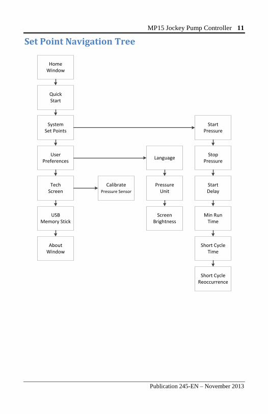
Set Point Navigation Tree
HomeWindow
SystemSet Points
UserPreferences
TechScreen
USBMemory Stick
AboutWindow
CalibratePressure Sensor
Language
PressureUnit
ScreenBrightness
StartPressure
StopPressure
StartDelay
Min RunTime
Short CycleTime
Short CycleReoccurrence
QuickStart
12 MP15 Jockey Pump Controller
Publication 245-EN – November 2013
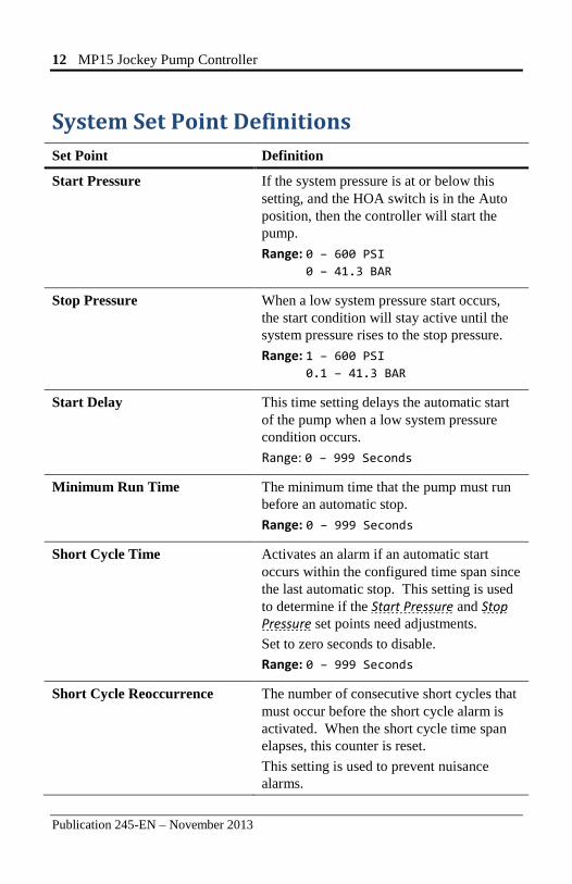
System Set Point Definitions
Set Point Definition
Start Pressure If the system pressure is at or below this
setting, and the HOA switch is in the Auto
position, then the controller will start the
pump.
Range: 0 – 600 PSI 0 – 41.3 BAR
Stop Pressure When a low system pressure start occurs,
the start condition will stay active until the
system pressure rises to the stop pressure.
Range: 1 – 600 PSI 0.1 – 41.3 BAR
Start Delay This time setting delays the automatic start
of the pump when a low system pressure
condition occurs.
Range: 0 – 999 Seconds
Minimum Run Time The minimum time that the pump must run
before an automatic stop.
Range: 0 – 999 Seconds
Short Cycle Time Activates an alarm if an automatic start
occurs within the configured time span since
the last automatic stop. This setting is used
to determine if the Start Pressure and Stop Pressure set points need adjustments.
Set to zero seconds to disable.
Range: 0 – 999 Seconds
Short Cycle Reoccurrence The number of consecutive short cycles that
must occur before the short cycle alarm is
activated. When the short cycle time span
elapses, this counter is reset.
This setting is used to prevent nuisance
alarms.
MP15 Jockey Pump Controller 13
Publication 245-EN – November 2013
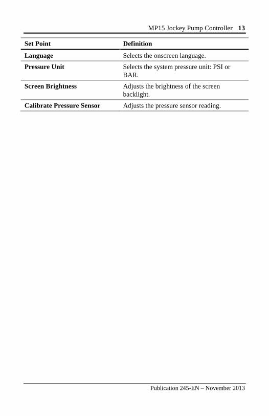
Set Point Definition
Language Selects the onscreen language.
Pressure Unit Selects the system pressure unit: PSI or
BAR.
Screen Brightness Adjusts the brightness of the screen
backlight.
Calibrate Pressure Sensor Adjusts the pressure sensor reading.

14 MP15 Jockey Pump Controller
Publication 245-EN – November 2013
Test Procedures Before beginning each test, verify system pressure is above the Start Pressure
setting. Turn the HOA switch to the Off position to clear all alarms.
Manual Start
1. Turn the HOA switch to the Hand position.
2. The pump should start immediately and the Pump Running LED should
turn on.
3. Turn the HOA switch to the Off position.
4. The pump should stop immediately and the Pump Running LED should
turn off.
Automatic Pressure Start
1. Turn the HOA switch to the Auto position.
2. Lower the system pressure below the configured Start Pressure.
3. The automatic start process will begin. Once the pump begins running,
it will continue to run until:
a. The HOA switch is set to the Off position, or
b. The system pressure rises above the configured Stop Pressure
and the Minimum Run Timer expires.

MP15 Jockey Pump Controller 15
Publication 245-EN – November 2013
Alarm and Event Log Messages The following lists all the possible messages that can be recorded within the data
log.
Message Description
Pump Running The pump has started running — manual
or automatic.
Pump Stopped The pump has stopped running — manual
or automatic.
Pressure Sensor Fault A pressure sensor fault alarm has occurred.
HOA Switch Fault An HOA Switch fault alarm has occurred.
Short Cycle Alarm A short cycle alarm has occurred.
Off Mode The HOA switch has been placed in the
Off position.
Auto Mode The HOA switch has been placed in the
Auto position.
Hand Mode The HOA switch has been placed in the
Hand position.
16 MP15 Jockey Pump Controller
Publication 245-EN – November 2013
Disposal Metron Eledyne is a member of a compliance scheme under the Waste Electrical
and Electronic Equipment regulations which is applicable in all EC countries. At
the end of the service life of the equipment the company offers to collect and
dispose of this equipment in accordance with regulations in force under the
Registration Number WEE/CF0105WV. (Equipment must be suitably packed
for collection by courier if outside the UK).
Contact:
Tel: +44 (0) 1476 516120
Fax: +44 (0) 1476 516121

MP-15 Jockey Pump Controller 17
www.metroninc.com www.metroneledyne.co.uk
Hubbell Industrial Controls, Inc. Metron Fire Pump Controls Division 4301 Cheyenne Drive, Archdale NC 27263 USA, Tel: (336) 434-2800, Fax: (336) 434-2803
Metron Eledyne a Division of Hubbell Ltd. 18 Autumn Park, Dysart Rd, Grantham Lincolnshire, NG31 7DD, United Kingdom Tel: +44 (0) 1476 516120, Fax: +44 (0) 1476 516121
Publication 245-EN – November 2013 Printed in USA.
Replacement Parts For replacement parts, contact your local Metron sales office or the Metron
factory at:
United States Telephone: +1 (336) 434-2800
FAX: +1 (336) 434-2809
Email: [email protected]
Europe Telephone: +44 (0) 1476 516130
Email: [email protected]
Technical Support
United States For 24-hour technical support:
Telephone: +1 (336) 434-2800 ext. 183
Email: [email protected]
Europe Service & Commissioning
Telephone: +44 (0) 1476 516129
Email: [email protected]
Emergency Contact:
Telephone: +44 (0) 7730 050100


![XT SERIES Jockey Pump Controllers 1-1 Features · MD05805161K/B For more information visit: Standard Enclosure - Type NEMA 2 - Jockey Pump Controller Dimensions in inches and [millimeters]](https://img.dokumen.tips/doc/110x75/60c4dcb1e6b67873120070de/xt-series-jockey-pump-controllers-1-1-features-md05805161kb-for-more-information.jpg)