Embed Size (px)
Citation preview
MMA, MRA;M20AP..., M24AP...;M50AP..., M55AP...; M54A...
Drehstrommotoren
AC motors
Moteurs triphasés
Motores trifásicos
Motoriftrifase
Ä.U1Pä
.U1P
Montageanleitung DE
EN
FR
ES
IT
Mounting Instructions
Instructions de montage
Instrucciones para el montaje
Istruzioni per il montaggio
M...
2
tab----(DUMMYSEITEVOR)---
Lenze • MA 33.0009 • 3.0
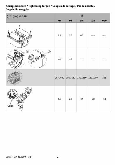
Anzugsmomente / Tightening torque / Couples de serrage / Par de apriete /Coppia di serraggio
[Nm] +/- 10%
M4 M5 M6 M8 M10
2.2 3.5 4.5 ----- -----
2.5 3.5 ----- ----- -----
063...080 090...112 132...160 180...200 225
CuZn
1.5 2.0 3.5 6.0 8.0
3
tab----(DUMMYSEITEVOR)---
Lenze • MA 33.0009 • 3.0
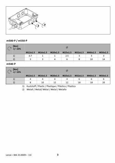
m500-P / m550-P
[Nm]+/- 10%
M12x1.5 M16x1.5 M20x1.5 M25x1.5 M32x1.5 M40x1.5 M50x1.5
1) 0.7 1 1 2.5 3 3 3
2) 3 3 4 6 8 10 14
m540-P
[Nm]+/- 10%
M12x1.5 M16x1.5 M20x1.5 M25x1.5 M32x1.5 M40x1.5 M50x1.5
1) 4 4 4 4 6 6 6
2) 8 10 12 12 18 18 20
1) Kuststoff / Plastic / Plastique / Plástico / Plastica2) Metall / Metal/ Métal / Metal / Metallo

4
tab----(DUMMYSEITEVOR)---
Lenze • MA 33.0009 • 3.0

5
tab----(DUMMYSEITEVOR)---
Lenze • MA 33.0009 • 3.0

6
tab----(DUMMYSEITEVOR)---
Lenze • MA 33.0009 • 3.0

7
tab----(DUMMYSEITEVOR)---
Lenze • MA 33.0009 • 3.0

8
tab----(DUMMYSEITEVOR)---
Lenze • MA 33.0009 • 3.0

Allgemeines
Lenze • MA 33.0009 • 3.0 9
H1_Allgemeines-UL-Warnings_DSMot
0 Allgemeines
Lesen Sie zuerst diese Anleitung, bevor Sie mit den Arbeiten beginnen!
Diese Anleitung ist nur gültig zusammen mit der Gesamtdokumentation desGrundgerätes und des Motors!
Für sicherheitsbewertete Anbauten ist die Betriebsanleitung des Herstellers zubeachten!
Tipp!Informationen und Hilfsmittel rund um die Lenze-Produkte finden Sie imDownload-Bereich unter
www.lenze.com
Gefahr!Wenn Sie die folgenden grundlegenden Sicherheitsmaßnahmenmissachten,kann dies zu schweren Personenschäden und Sachschäden führen:
Hinweis!Alle Farbenkennzeichnungen beziehen sich auf Lenze Systemleitungen!
Warnings!Wichtige Hinweise zur Montage von Motoren mit Flansch in UL-approbiertenAnlagen:
Im Motorgehäuse befinden sich Gewindelöcher oder Durchgangsbohrungen.ƒ Diese Löcher dürfen nicht für die Montage von Füßen benutzt werden.ƒ Diese Motoren dürfen Sie nur fest und ohne Füße montieren.

Sicherheitshinweise
Lenze • MA 33.0009 • 3.0 10
H1sic_DE-sicherheit-MA-mot
1 Sicherheitshinweise
ƒ Lenze-Antriebs- und Automatisierungskomponenten ...... ausschließlich bestimmungsgemäß verwenden.... niemals trotz erkennbarer Schäden in Betrieb nehmen.... niemals technisch verändern.... niemals unvollständig montiert in Betrieb nehmen.... niemals ohne erforderliche Abdeckungen betreiben.... könnenwährend und nach demBetrieb - ihrer Schutzart entsprechend - spannungs-führende, auchbeweglicheoder rotierendeTeilehaben.Oberflächenkönnenheiß sein.
ƒ Alle Vorgaben der beiliegenden und zugehörigen Dokumentation beachten.Dies ist Voraussetzung für einen sicheren und störungsfreien Betrieb sowie für das Er-reichen der angegebenen Produkteigenschaften.
ƒ Alle Arbeiten mit und an Lenze-Antriebs- und Automatisierungskomponenten darfnur qualifiziertes Fachpersonal ausführen.Nach IEC 60364 bzw. CENELEC HD 384 sind dies Personen, ...... die mit Aufstellung, Montage, Inbetriebsetzung und Betrieb des Produkts vertrautsind.... die über die entsprechenden Qualifikationen für ihre Tätigkeit verfügen.... die alle am Einsatzort geltenden Unfallverhütungsvorschriften, Richtlinien und Ge-setze kennen und anwenden können.
ƒ Lebensgefährliche Spannung an den Leistungsanschlüssen, auch bei abgezogenemStecker: Restspannung >60 V!
ƒ Vor Arbeiten an den Leistungsanschlüssen Motor und wenn vorhandenAntriebsregler unbedingt vom Netz trennen und warten, bis der Motor stillsteht(Spannung bei drehendemMotor an den Kontakten).
ƒ Verbrennungsgefahr!– Während des Betriebs heiße Oberflächen bis 140 °C! Berührschutz vorsehen.
ƒ Verletzungsgefahr durch drehendeWelle!– Vor Arbeiten amMotor warten bis Motor stillsteht.
ƒ Ausführung mit Stecker:– Stecker niemals unter Spannung ziehen! Der Stecker kann sonst zerstört werden.– Vor Abziehen des Steckers Spannungsvorsorgung abschalten bzw. Antriebsregler
sperren.

Installation
Lenze • MA 33.0009 • 3.0 11
H1inst-beidseitig-schirmanbindung
2 Installation
Montagehinweis
Stop!Maximal zulässige Anschraubtiefe bei B14-Flansch beachten,Betriebsanleitung!
ƒ Zum Transport Traghilfen benutzen!ƒ Nicht auf die Welle schlagen! Motor kann zerstört werden! Abtriebselemente nur
über Gewinde in der Motorwelle montieren, mit Abziehwerkzeug demontieren.Kupplung fest anziehen.
ƒ Motor sicher befestigen, für ungehinderte Belüftung sorgen.ƒ Überwurfmuttern der Stecker fest anziehen.ƒ Motor sorgfältig erden, Verdrahtung kontrollieren.ƒ Schirme der Motorleitung großflächig amMotor und am Antriebsregler auflegen.
Elektrischer Anschluss
Hinweis!Für den sicheren Betrieb sind die Anzugsmomente mit einer Toleranz von+- 10% einzuhalten (2).
Steckverbindung
Beim Zusammenstecken des Kabel-Steckverbindersmit demMotorstecker darauf achten,dass die Orientierungshilfe (Pos.1) gegenüberliegen. Nur so ist ein störungsfreier Betriebgewährleistet.ƒ Überwurfmutter der Kabel-Steckverbinder fest anziehen!ƒ Kabel-Steckverbinder niemals unter Spannung ziehen! Der Stecker kann sonst
zerstört werden! Vor dem Abziehen den Antriebsregler sperren!

Installation
Lenze • MA 33.0009 • 3.0 12
H1inst-beidseitig-schirmanbindung
Klemmenbrett
Eintourige Motoren Polumschaltbare Motoren MMA
PE
L1 L2 L3
(1)TB1 (1)TB2
W2 U2 V2
U1 V1 W1
L1 L2 L3
W2 U2 V2
U1 V1 W1
PE(1)TB1 (1)TB2
L1 L2 L3
U2 V2 W2
U1 V1 W1
L1 L2 L3
U1 V1 W1
U2 V2 W2
A B(1)TB1 (1)TB2 (1)TB1 (1)TB2
MT_MXXXX_001.iso/dms
Spannungsumschaltbare Motoren
M20AP, M24AP, M50AP, M55AP MMA, M54A
L1 L2 L3
V5
U1 V1 W1
U5 W5
U2 V2 W2
L1 L2 L3
U1 V1 W1
U5 W5
U2 V2 W2
V5
L1 L2 L3
V3
U1 V1 W1
U3 W3
U2 V2 W2
L1 L2 L3
U1 V1 W1
U3 W3
U2 V2 W2
V3
MT_MXXXX_001.iso/dms
Legende zu den Schaltbildern
L1/L2/L3 Leistungsanschluss
(1)TB1 / (1)TB2 Thermokontakt (TKO)
Niedrige Drehzahl
Hohe Drehzahl
Niedrige Spannung
Hohe Spannung
PE-Anschluss (optional)

Installation
Lenze • MA 33.0009 • 3.0 13
H1inst-beidseitig-schirmanbindung
Anschluss Fremdlüfter über Fremdlüfterklemmenkasten/Motorklemmenkasten
Fremdlüfter 3~
Klemmenbrett
Kontakt Bedeutung Hinweis
U1 Anschluss an L1 - NetzDrehrichtung beachten! Bei falscher Drehrichtung L1- L2 vertauschenV1 Anschluss an L2 - Netz
W1 Anschluss an L3 - Netz
Fremdlüfter 1~
Klemmenbrett
Kontakt Bedeutung Hinweis
U1 Anschluss an L1- Netz
V1 / U2 Anschluss an N - Netz
Anschluss Temperaturüberwachung
Klemmenleiste / Klemmenbrett
Kontakt Bedeutung Hinweis
(1)TB1 Thermokontakt TKO max. 250 V ~max. 1.6 A ~(1)TB2
(1)TP1 Kaltleiter PTC
(1)TP2
(1)R1 Temperatursensor +KTYPolarität beachten
(1)R2 Temperatursensor -KTY
Klemmenbrett oder Klemme für alle Thermofühler möglich.

Installation
Lenze • MA 33.0009 • 3.0 14
H1inst-beidseitig-schirmanbindung
Anschluss Bremse
Kontakt Bedeutung Zusatz
~ Bremse wechselstromerregt (Gleichrich-ter) Anschluss an L1 - Netz
~1 2 3 4 5 6
- ~ ~ +
Anschluss an N - Netz
+ Anschluss an Bremse
- Anschluss an Bremse
Schaltkontakt gleichstromseitigesSchalten
(1)BD1 Bremse gleichstromerregt Gleichstromanschluss
(1)BD2
MS1 / 2S1 Mikroschalter Bremse Lüftkontrolle Wechselkontakt
MS2 / 2S2 Öffner
MS4 / 2S3 Schließer
MS1 / 3S1 Mikroschalter Bremse Verschleißkon-trolle
Wechselkontakt
MS2 / 3S2 Öffner
MS4 / 3S3 Schließer
MS1 Mikroschalter Bremse Handlüftung Wechselkontakt
MS2 Öffner
MS4 Schließer

Installation
Lenze • MA 33.0009 • 3.0 15
H1inst-beidseitig-schirmanbindung
Anschluss Rückführsystem
Resolver
Kontakt Bezeichnung Bedeutung
B1B2
+ Ref- Ref
Transformatorwicklungen (Referen-zwicklungen)
B3 nicht belegt
B4B5
+ COS- COS
Ständerwicklung Cosinus
B6B7
+ SIN- SIN
Ständerwicklung Sinus
B8 nicht belegt
Inkrementalgeber / Sin-Cos-Absolutwertgeber mit Hiperface
Kontakt Bezeichnung Bedeutung
B1B2
+ UBGND
Versorgung +Masse
B3B4
A / + COSA / Ref cos
Spur A / ProzessdatenkanalSpur A invers / Prozessdatenkanal
B5B6
B / + SINB / Ref sin
Spur B / ProzessdatenkanalSpur B invers / Prozessdatenkanal
B7B8
Z / Daten +Z / Daten -
Nullspur / Pararmeterkanal + RS485Nullspur invers / Pararmeterkanal - RS485
B10 1) Schirm Geh. Inkrementalgeber Schirm
1) Der Kontakt ist nicht belegt bei Option B-seitig isoliertemMotorlager!
Hinweis!ƒ Signalleitung geschirmt ausführen.
ƒ Auf beidseitige Schirmanbindung achten.

General information
Lenze • MA 33.0009 • 3.0 16
H1_Allgemeines-UL-Warnings_DSMot
3 General Information
Please read these instructions before you start working!
These instructions are only valid with the overall documentation of thestandard device and the motor!
For safety-rated built-on accessories, the manufacturer’s operatinginstructions have to be observed!
Tip!Information and tools concerning the Lenze products can be found in thedownload area at
www.lenze.com
Danger!Disregarding the following basic safety measures may lead to severe personalinjury and damage to material assets!
Note!The colour coding scheme refers to Lenze system cables!
Warnings!Important installation instructions for flange-mounted motors
The operating instructions indicate that the motor housing has threaded holesor through holes.ƒ These holes may not be used to install feet.ƒ Motor mounting is only allowed as fixed installation without feet.
Safety instructions
Lenze • MA 33.0009 • 3.0 17
H1sic_EN-sicherheit-MA-mot
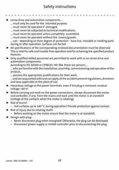
4 Safety instructions
ƒ Lenze drive and automation components ...... must only be used for the intended purpose.... must never be operated if damaged.... must never be subjected to technical modifications.... must never be operated unless completely assembled.... must never be operated without the covers/guards.... can - depending on their degree of protection - have live, movable or rotating partsduring or after operation. Surfaces can be hot.
ƒ All specifications of the corresponding enclosed documentation must be observed.This is vital for safe and trouble-free operation and for achieving the specified productfeatures.
ƒ Only qualified skilled personnel are permitted to work with or on Lenze drive andautomation components.According to IEC 60364 or CENELEC HD 384, these are persons ......whoare familiarwith the installation, assembly, commissioningandoperationof theproduct,... possess the appropriate qualifications for their work,... andareacquaintedwithandcanapplyall theaccidentprevent regulations, directivesand laws applicable at the place of use.
ƒ Hazardous voltage at the power terminals, even if the plug is removed: residualvoltage >60 V!
ƒ Before carrying out work on the power connections, always disconnect the motorand controller, if any, from the mains and wait until the motor is at standstill(voltage at the contacts when the motor is rotating).
ƒ Risk of burns!– Hot surfaces up to 140 °C during operation! Provide protection against contact.
ƒ Risk of injury due to rotating shaft!– Before working on the motor ensure that the motor is at standstill.
ƒ Design with plug:– Never disconnect plug when energised! Otherwise, the plug can be destroyed.– Disconnect power supply or inhibit controller prior to disconnecting the plug.
Installation
Lenze • MA 33.0009 • 3.0 18
H1inst-beidseitig-schirmanbindung
5 Installation
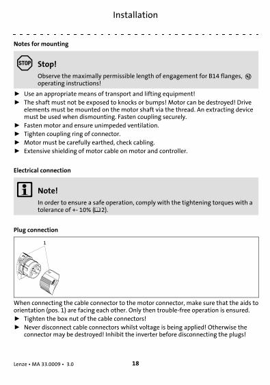
Notes for mounting
Stop!Observe the maximally permissible length of engagement for B14 flanges, operating instructions!
ƒ Use an appropriate means of transport and lifting equipment!ƒ The shaft must not be exposed to knocks or bumps! Motor can be destroyed! Drive
elements must be mounted on the motor shaft via the thread. An extracting devicemust be used when dismounting. Fasten coupling securely.
ƒ Fasten motor and ensure unimpeded ventilation.ƒ Tighten coupling ring of connector.ƒ Motor must be carefully earthed, check cabling.ƒ Extensive shielding of motor cable on motor and controller.
Electrical connection
Note!In order to ensure a safe operation, comply with the tightening torques with atolerance of +- 10% (2).
Plug connection
When connecting the cable connector to the motor connector, make sure that the aids toorientation (pos. 1) are facing each other. Only then trouble-free operation is ensured.ƒ Tighten the box nut of the cable connectors!ƒ Never disconnect cable connectors whilst voltage is being applied! Otherwise the
connector may be destroyed! Inhibit the inverter before disconnecting the plugs!
Installation
Lenze • MA 33.0009 • 3.0 19
H1inst-beidseitig-schirmanbindung
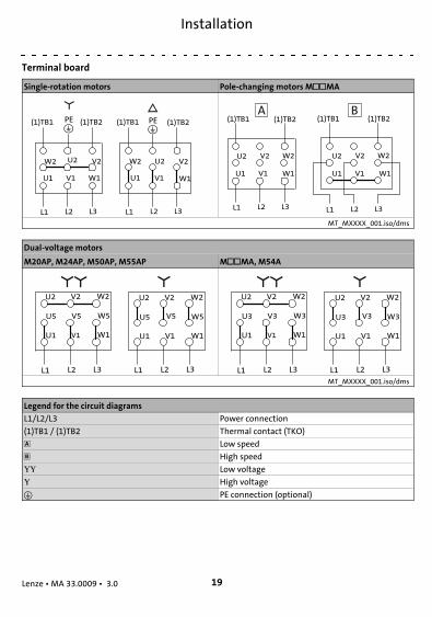
Terminal board
Single-rotation motors Pole-changing motors MMA
PE
L1 L2 L3
(1)TB1 (1)TB2
W2 U2 V2
U1 V1 W1
L1 L2 L3
W2 U2 V2
U1 V1 W1
PE(1)TB1 (1)TB2
L1 L2 L3
U2 V2 W2
U1 V1 W1
L1 L2 L3
U1 V1 W1
U2 V2 W2
A B(1)TB1 (1)TB2 (1)TB1 (1)TB2
MT_MXXXX_001.iso/dms
Dual-voltage motors
M20AP, M24AP, M50AP, M55AP MMA, M54A
L1 L2 L3
V5
U1 V1 W1
U5 W5
U2 V2 W2
L1 L2 L3
U1 V1 W1
U5 W5
U2 V2 W2
V5
L1 L2 L3
V3
U1 V1 W1
U3 W3
U2 V2 W2
L1 L2 L3
U1 V1 W1
U3 W3
U2 V2 W2
V3
MT_MXXXX_001.iso/dms
Legend for the circuit diagrams
L1/L2/L3 Power connection
(1)TB1 / (1)TB2 Thermal contact (TKO)
Low speed
High speed
Low voltage
High voltage
PE connection (optional)
Installation
Lenze • MA 33.0009 • 3.0 20
H1inst-beidseitig-schirmanbindung
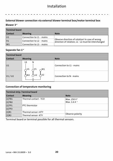
External blower connection via external blower terminal box/motor terminal box
Blower 3~
Terminal board
Contact Meaning Note
U1 Connection to L1 - mainsObserve direction of rotation! In case of wrongdirection of rotation, L1 - L2 must be interchangedV1 Connection to L2 - mains
W1 Connection to L3 - mains
Separate fan 1~
Terminal board
Contact Meaning Note
U1 Connection to L1 - mains
V1 / U2 Connection to N - mains
Connection of temperature monitoring
Terminal strip / terminal board
Contact Meaning Note
(1)TB1 Thermal contact - TCO Max. 250 V~Max. 1.6 A ~(1)TB2
(1)TP1 PTC thermistor
(1)TP2
(1)R1 Thermal sensor +KTYObserve polarity
(1)R2 Thermal sensor -KTY
Terminal board or terminal possible for all thermal sensors.

Installation
Lenze • MA 33.0009 • 3.0 21
H1inst-beidseitig-schirmanbindung
Brake connection
Contact Meaning Additional specifications
~ AC-excited brake (rectifier) Connection to L1 - mains
~1 2 3 4 5 6
- ~ ~ +
Connection to N - mains
+ Brake connection
- Brake connection
Switching contact, DC switching
(1)BD1 Brake, DC operated DC connection
(1)BD2
MS1 / 2S1 Brake microswitch, release control Two-way switch
MS2 / 2S2 NC contact
MS4 / 2S3 NO contact
MS1 / 3S1 Brake microswitch, wear control Two-way switch
MS2 / 3S2 NC contact
MS4 / 3S3 NO contact
MS1 Brake microswitch, manual release Two-way switch
MS2 NC contact
MS4 NO contact

Installation
Lenze • MA 33.0009 • 3.0 22
H1inst-beidseitig-schirmanbindung
Connection of feedback system
Resolver
Contact Name Meaning
B1B2
+ Ref- Ref
Transformer windings (referencewindings)
B3 Not assigned
B4B5
+COS-COS
Stator winding cosine
B6B7
+SIN-SIN
Stator winding sine
B8 Not assigned
Incremental encoder / sin/cos absolute value encoder with Hiperface
Contact Designation Meaning
B1B2
+ UBGND
Supply +Mass
B3B4
A / + COSA / Ref cos
Track A / process data channelTrack A inverse / process data channel
B5B6
B / + SINB / Ref sin
Track B / process data channelTrack B inverse / process data channel
B7B8
Z / data +Z / data -
Zero track / parameter channel + RS485Zero track inverse / parameter channel - RS485
B10 1) Shield - housing Shield - incremental encoder
1) The terminal is not assigned if insulation at N-end shield of the motor has been selected!
Note!ƒ Shield signal cable.ƒ Connect shield on both sides.

Généralités
Lenze • MA 33.0009 • 3.0 23
H1_Allgemeines-UL-Warnings_DSMot
6 Généralités
Veuillez lire attentivement cette documentation avant toute action !
Le présent fascicule n’est valable que conjointement avec la documentationcomplète de l’appareil de base et du moteur !
Pour les pièces assemblées de sécurité, tenir compte des instructions de miseen service du fabricant !
Conseil !Toutes les informations relatives aux produits Lenze peuvent être téléchargéessur notre site à l’adresse suivante :
www.Lenze.com
Danger !Le non-respect des consignes fondamentales de sécurité suivantes peutentraîner des blessures et des dommages matériels graves.
Remarque importante !Les désignations de couleur se rapportent aux câbles système Lenze !
Avertissements !Instructions de montage importantes pour moteurs à flasque-bride dans lesinstallations homologuées UL :
Les instructions de mise en service précisent que les flasques-brides desmoteurs sont percés de trous taraudés ou de trous lisses.ƒ Ces trous ne doivent pas être utilisés pour monter des pattes.ƒ Le montage du moteur n’est autorisé qu’en installation fixe et sans pattes.
Consignes de sécurité
Lenze • MA 33.0009 • 3.0 24
H1sic_FR-sicherheit-MA-mot
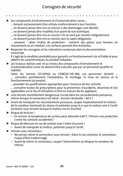
7 Consignes de sécurité
ƒ Les composants d’entraînement et d’automatisation Lenze ...... doivent exclusivement être utilisés conformément à leur fonction.... ne doivent jamais être mis en service si des dommages sont décelés.... ne doivent jamais être modifiés d’un point de vue technique.... ne doivent jamais être mis en service s’ils ne sont pas montés intégralement.... ne doivent jamais être mis en service sans le capot obligatoire.... peuvent - selon l’indice de protection - contenir des pièces sous tension, enmouvement ou en rotation. Les surfaces peuvent être brûlantes.
ƒ Respecter les consignes et les indications contenues dans la documentationconcernée.Il s’agit de la condition préalable pour garantir un fonctionnement sûr et fiable et pourobtenir les caractéristiques du produit indiquées.
ƒ Les travaux réalisés avec et au niveau des composants d’entraînement etd’automatisation Lenze ne doivent être exécutés que par un personnel qualifié ethabilité.Selon les normes CEI 60364 ou CENELEC HD 384, ces personnes doivent ...... connaître parfaitement l’installation, le montage, la mise en service et lefonctionnement du produit.... posséder les qualifications appropriées pour l’exercice de leur activité.... connaître toutes les prescriptions pour la prévention d’accidents, directives et loisapplicables sur le lieu d’utilisation et être en mesure de les appliquer.
ƒ Une tension mortellement dangereuse circule dans les raccordements puissance,même lorsque le connecteur est retiré : tension résiduelle > 60 V !
ƒ Avant de manipuler les raccordements puissance, couper impérativement le moteur(et le variateur éventuel) du réseau et patienter jusqu’à ce que le moteur soit à l’arrêt(contacts sous tension lorsque le moteur est en marche).
ƒ Risque de brûlure !– En service, la température de surface peut atteindre 140°C ! Prévoir une protection
contre les contacts accidentels !ƒ Risque de blessure en cas de contact avec l’arbre tournant !
– Avant de manipuler le moteur, patienter jusqu’à l’arrêt.ƒ Version avec connecteur :
– Ne jamais retirer le connecteur sous tension ! Dans le cas contraire, le connecteurrisque d’être endommagé.
– Avant de retirer le connecteur, couper l’alimentation ou bloquer le variateur devitesse.
Installation
Lenze • MA 33.0009 • 3.0 25
H1inst-beidseitig-schirmanbindung
8 Installation
Remarque concernant le montage
Stop !Tenir compte de la profondeur de serrage max. admissible pour les brides B14, Instructions de montage !
ƒ Utiliser les dispositifs d’aide au transport !ƒ Éviter tout choc sur l’arbre ! Le moteur pourrait être endommagé ! Monter les
éléments de transmission sur l’arbre en utilisant impérativement les trous taraudés.Pour les démonter, utiliser l’outil d’extraction. Veiller à ce que l’accouplement soitbien serré.
ƒ Bien fixer le moteur ; veiller à ce que la ventilation ne soit pas entravée.ƒ Bien serrer les collerettes de fixation des connecteurs.ƒ Relier le moteur à la terre avec soin ; contrôler le câblage.ƒ Appliquer une surface de contact importante entre les blindages du câble moteur et
le moteur/variateur.Raccordement électrique
Remarque importante !Respecter les couples de serrage indiqués (tolérance +- 10 %) afin d’assurer unfonctionnement sûr (2).
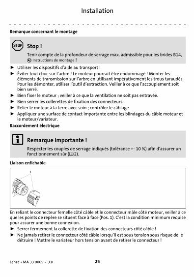
Liaison enfichable
En reliant le connecteur femelle côté câble et le connecteur mâle côté moteur, veiller à ceque les points de repère se situent face à face (Pos. 1). C’est la conditionminimum requisepour assurer une bonne connexion.ƒ Serrer fermement la collerette de fixation des connecteurs côté câble !ƒ Ne jamais retirer le connecteur côté câble lorsqu’il est sous tension sous risque de le
détruire ! Mettre le variateur hors tension avant de retirer le connecteur !

Installation
Lenze • MA 33.0009 • 3.0 26
H1inst-beidseitig-schirmanbindung
Plaque à bornes
Moteurs standard étoile triangle Moteurs bi-vitesse MMA
PE
L1 L2 L3
(1)TB1 (1)TB2
W2 U2 V2
U1 V1 W1
L1 L2 L3
W2 U2 V2
U1 V1 W1
PE(1)TB1 (1)TB2
L1 L2 L3
U2 V2 W2
U1 V1 W1
L1 L2 L3
U1 V1 W1
U2 V2 W2
A B(1)TB1 (1)TB2 (1)TB1 (1)TB2
MT_MXXXX_001.iso/dms
Moteurs bi-tension
M20AP, M24AP, M50AP, M55AP MMA, M54A
L1 L2 L3
V5
U1 V1 W1
U5 W5
U2 V2 W2
L1 L2 L3
U1 V1 W1
U5 W5
U2 V2 W2
V5
L1 L2 L3
V3
U1 V1 W1
U3 W3
U2 V2 W2
L1 L2 L3
U1 V1 W1
U3 W3
U2 V2 W2
V3
MT_MXXXX_001.iso/dms
Légende
L1/L2/L3 Raccordement puissance
(1)TB1 / (1)TB2 Contact thermique (TKO)
Faible vitesse
Vitesse élevée
Basse tension
Haute tension
Raccord PE (option)
Installation
Lenze • MA 33.0009 • 3.0 27
H1inst-beidseitig-schirmanbindung
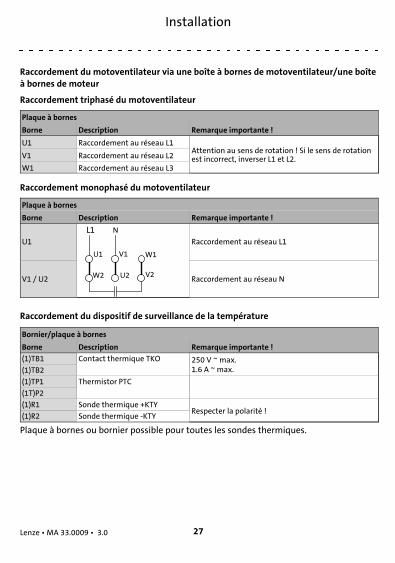
Raccordement du motoventilateur via une boîte à bornes de motoventilateur/une boîteà bornes de moteur
Raccordement triphasé du motoventilateur
Plaque à bornes
Borne Description Remarque importante !
U1 Raccordement au réseau L1Attention au sens de rotation ! Si le sens de rotationest incorrect, inverser L1 et L2.V1 Raccordement au réseau L2
W1 Raccordement au réseau L3
Raccordement monophasé du motoventilateur
Plaque à bornes
Borne Description Remarque importante !
U1 Raccordement au réseau L1
V1 / U2 Raccordement au réseau N
Raccordement du dispositif de surveillance de la température
Bornier/plaque à bornes
Borne Description Remarque importante !
(1)TB1 Contact thermique TKO 250 V ~ max.1.6 A ~ max.(1)TB2
(1)TP1 Thermistor PTC
(1T)P2
(1)R1 Sonde thermique +KTYRespecter la polarité !
(1)R2 Sonde thermique -KTY
Plaque à bornes ou bornier possible pour toutes les sondes thermiques.
Installation
Lenze • MA 33.0009 • 3.0 28
H1inst-beidseitig-schirmanbindung
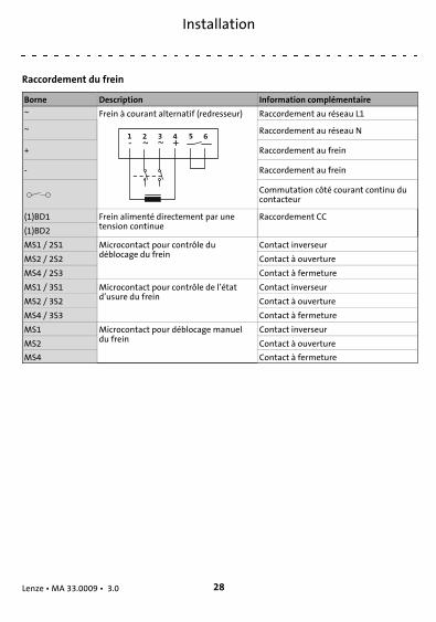
Raccordement du frein
Borne Description Information complémentaire
~ Frein à courant alternatif (redresseur) Raccordement au réseau L1
~1 2 3 4 5 6
- ~ ~ +
Raccordement au réseau N
+ Raccordement au frein
- Raccordement au frein
Commutation côté courant continu ducontacteur
(1)BD1 Frein alimenté directement par unetension continue
Raccordement CC
(1)BD2
MS1 / 2S1 Microcontact pour contrôle dudéblocage du frein
Contact inverseur
MS2 / 2S2 Contact à ouverture
MS4 / 2S3 Contact à fermeture
MS1 / 3S1 Microcontact pour contrôle de l’étatd’usure du frein
Contact inverseur
MS2 / 3S2 Contact à ouverture
MS4 / 3S3 Contact à fermeture
MS1 Microcontact pour déblocage manueldu frein
Contact inverseur
MS2 Contact à ouverture
MS4 Contact à fermeture

Installation
Lenze • MA 33.0009 • 3.0 29
H1inst-beidseitig-schirmanbindung
Raccordement du système de bouclage
Résolveur
Borne Désignation Description
B1B2
+Ref-Ref
Enroulements de transformateur(enroulements de référence)
B3 Non affectée
B4B5
+COS-COS
Enroulement statorique, cosinus
B6B7
+SIN-SIN
Enroulement statorique, sinus
B8 Non affectée
Codeur incrémental/absolu SinCos avec Hiperface
Borne Désignation Description
B1B2
+ UBGND
Alimentation +Masse
B3B4
A / + COSA / Ref cos
Voie A / canal de données processVoie A compl. / canal de données process
B5B6
B / + SINB / Ref sin
Voie B / canal de données processVoie B compl. / canal de données process
B7B8
Z / données +Z / données -
Top zéro / canal de données paramètres + RS485Top zéro compl. / canal de données paramètres - RS485
B10 1) Blindage du boîtier Blindage du codeur incrémental
1) Borne non affectée si support moteur isolé côté B !
Remarque importante !ƒ Blinder les câbles de signaux.ƒ Raccorder les blindages des câbles aux deux extrémités.

Aspectos generales
Lenze • MA 33.0009 • 3.0 30
H1_Allgemeines-UL-Warnings_DSMot
9 Aspectos generales
¡Lea estas instrucciones antes de empezar con los trabajos!
¡Estas instrucciones sólo son válidas junto con la documentación junto con ladocumentación completa del equipo básico y del motor!
¡Para ampliaciones relacionadas con la seguridad deberá observarse el manualde operaciones del fabricante!
¡Sugerencia!Encontrará información y consejos sobre los productos de Lenze en el área dedescargas en
www.lenze.com
¡Peligro!Si no se observan las siguientes instrucciones básicas de seguridad, puedenocasionarse serios daños a personas y materiales:
¡Aviso!¡Todas las marcas de color se refieren a cables de sistema de Lenze!
Warnings !Información importante sobre el montaje de motores con brida eninstalaciones con aprobación UL:
En la carcasa del motor se encuentran taladros roscados o agujeros de paso.ƒ Estos agujeros no deben ser utilizados para el montaje de patas.ƒ Estos motores sólo deben ser montados de manera fija y sin patas.
Instrucciones de seguridad
Lenze • MA 33.0009 • 3.0 31
H1sic_ES-sicherheit-MA-mot
10 Instrucciones de seguridad
ƒ Los componentes de accionamiento y automatización de Lenze ...... sólo deben utilizarse de la manera adecuada.... nunca deben ponerse en funcionamiento si existen daños visibles.... nunca deben someterse amodificaciones técnicas.... nunca deben ponerse en funcionamiento si no están completamente montados.... nunca deben ponerse en funcionamiento sin las cubiertas necesarias.... pueden incluir durante y después del funcionamiento, y dependiendo de su gradodeprotección, piezas vivas, así como móviles y giratorias. Las superficies pueden estarcalientes.
ƒ Observe todas las indicaciones de la documentación adjunta y la documentacióncorrespondiente.Es requisito esencial paraun funcionamiento seguroy sin fallos,así comopara lograrlascaracterísticas declaradas del producto.
ƒ Todos los trabajos con y en componentes de accionamiento y automatización deLenze sólo deben ser realizados por personal experto cualificado.Según IEC 60364 o resp. CENELEC HD 384 se trata de personas, ...... que conocen la instalación, el montaje, la puesta en marcha y la operación delproducto.... que disponen de las cualificaciones correspondientes a su trabajo.... que conoceny sabenaplicar todas las normasde prevenciónde accidentes, directivasy leyes aplicables en el lugar de uso.
ƒ ¡Voltaje mortal en las conexiones de potencia, incluso una vez retirado el conector:voltaje residual >60 V!
ƒ Antes de realizar trabajos en las conexiones de potencia del motor es indispensableseparar el motor, y caso de existir, el convertidor, de la red y esperar hasta que elmotor se haya parado (con el motor girando, los contactos siguen vivos).
ƒ ¡Peligro de quemaduras!– ¡Durante el funcionamiento algunas superficies alcanzan los 140 °C! Prever
protección contra el contacto.ƒ ¡Peligro de lesiones por eje girando!
– Antes de trabajar en el motor esperar a que éste se detenga.ƒ Versión con conector:
– ¡Nunca retirar el conector habiendo voltaje! En caso contrario, el conector podríaresultar dañado.
– Antes de retirar el conector desconectar la alimentación de voltaje e inhibir elconvertidor.
Instalación
Lenze • MA 33.0009 • 3.0 32
H1inst-beidseitig-schirmanbindung
11 Instalación
Nota sobre el montaje
¡Alto!¡Observar la profundidad máxima de atornillado permitida para la brida B14,Manual de instrucciones.
ƒ ¡Utilizar las ayudas de carga para el transporte!ƒ ¡No golpear sobre el eje! ¡El motor podría resultar dañado! Montar los elementos del
lado salida en el eje del motor sólo a través de roscas y desmontarlos conherramientas de extracción. Apretar bien el acoplamiento.
ƒ Asegurar firmemente el motor, garantizar ventilación sin obstáculos.ƒ Apretar firmemente las tuercas de unión.ƒ Poner el motor a tierra adecuadamente, controlar el cableado.ƒ Colocar las mallas con gran superficie en el motor y en el convertidor.Conexión eléctrica
¡Aviso!Para un uso seguro, respete los pares de apriete con una tolerancia de+- 10% (2).
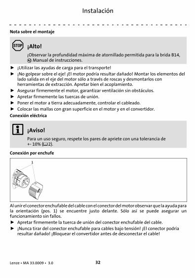
Conexión por enchufe
Alunirelconectorenchufabledelcableconelconectordelmotorobservarquelaayudaparala orientación (pos. 1) se encuentre justo delante. Sólo así se puede asegurar unfuncionamiento sin fallos.ƒ Apretar firmemente la tuerca de unión del conector enchufable del cable.ƒ ¡Nunca tirar del conector enchufable para cables bajo tensión! ¡El conector podría
resultar dañado! ¡Bloquear el convertidor antes de desconectar el cable!
Instalación
Lenze • MA 33.0009 • 3.0 33
H1inst-beidseitig-schirmanbindung
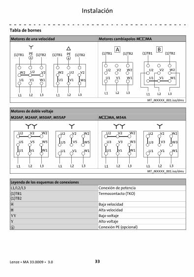
Tabla de bornes
Motores de una velocidad Motores cambiapolos MMA
PE
L1 L2 L3
(1)TB1 (1)TB2
W2 U2 V2
U1 V1 W1
L1 L2 L3
W2 U2 V2
U1 V1 W1
PE(1)TB1 (1)TB2
L1 L2 L3
U2 V2 W2
U1 V1 W1
L1 L2 L3
U1 V1 W1
U2 V2 W2
A B(1)TB1 (1)TB2 (1)TB1 (1)TB2
MT_MXXXX_001.iso/dms
Motores de doble voltaje
M20AP, M24AP, M50AP, M55AP MMA, M54A
L1 L2 L3
V5
U1 V1 W1
U5 W5
U2 V2 W2
L1 L2 L3
U1 V1 W1
U5 W5
U2 V2 W2
V5
L1 L2 L3
V3
U1 V1 W1
U3 W3
U2 V2 W2
L1 L2 L3
U1 V1 W1
U3 W3
U2 V2 W2
V3
MT_MXXXX_001.iso/dms
Leyenda de los esquemas de conexiones
L1/L2/L3 Conexión de potencia
(1)TB1(1)TB2
Termocontacto (TKO)
Baja velocidad
Alta velocidad
Bajo voltaje
Alto voltaje
Conexión PE (opcional)

Instalación
Lenze • MA 33.0009 • 3.0 34
H1inst-beidseitig-schirmanbindung
Conexionado de la ventilación forzada a través de caja de bornes de la ventilaciónforzada / del motor
Desbloqueo externo 3~
Tabla de bornes
Contacto Significado ¡Aviso!
U1 Conexión a red L1¡Observar dirección de giro! Si la dirección de giro esincorrecta, intercambiar L1 - L2V1 Conexión a red L2
W1 Conexión a red L3
Desbloqueo externo 1~
Tabla de bornes
Contacto Significado ¡Aviso!
U1 Conexión a red L1
V1 / U2 Conexión a red N
Conexionado de la monitorización de temperatura
Regleta/tabla de bornes
Contacto Significado ¡Aviso!
(1)TB1 Termocontacto TKO máx. 250 V ~máx. 1.6 A ~(1)TB2
(1)TP1 PTC
(1)TP2
(1)R1 Sensor de temperatura +KTYObservar polaridad
(1)R2 Sensor de temperatura -KTY
Tabla de bornes o borne posible para todos los sensores de temperatura.

Instalación
Lenze • MA 33.0009 • 3.0 35
H1inst-beidseitig-schirmanbindung
Conexionado del freno
Contacto Significado Añadido
~ Freno excitado por corriente alterna(rectificador) Conexión a red L1
~1 2 3 4 5 6
- ~ ~ +
Conexión a red N
+ Conexión al freno
- Conexión al freno
Contacto de conmutación, conmutaciónen lado corriente continua
(1)BD1 Freno excitado por corriente continua Conexión a corriente continua
(1)BD2
MS1 / 2S1 Microrruptor freno control dedesbloqueo
Contacto inversor
MS2 / 2S2 Contacto NC
MS4 / 2S3 Contacto NA
MS1 / 3S1 Microrruptor freno control de desgaste Contacto inversor
MS2 / 3S2 Contacto NC
MS4 / 3S3 Contacto NA
MS1 Microrruptor freno desbloqueo manual Contacto inversor
MS2 Contacto NC
MS4 Contacto NA

Instalación
Lenze • MA 33.0009 • 3.0 36
H1inst-beidseitig-schirmanbindung
Conexión sistema de realimentación
Resolver
Contacto Denominación Significado
B1B2
+Ref-Ref
Bobinados de transformador(bobinados de referencia)
B3 no asignado
B4B5
+COS-COS
Bobinado del estator coseno
B6B7
+SIN-SIN
Bobinado del estator seno
B8 no asignado
Encoder incremental / encoder de valores absolutos Sin-Cos con hyperface
Contacto Denominación Significado
B1B2
+ UBGND
Alimentación +Masa
B3B4
A / + COSA / Ref cos
Canal A / canal de datos de procesoCanal A inverso / canal de datos de proceso
B5B6
B / + SINB / Ref sin
Canal B / canal de datos de procesoCanal B inverso / canal de datos de proceso
B7B8
Z / datos +Z / datos -
Canal cero / canal de parámetros + RS485Canal cero inverso / canal de parámetros - RS485
B10 1) Malla carcasa Encoder incremental malla
1) ¡En la opción soporte de motor aislado en el lado B el borne no está ocupado!
¡Aviso!ƒ El cable de señales debe estar apantallado.ƒ La malla debe estar conectada a ambos lados.

Informazioni generali
Lenze • MA 33.0009 • 3.0 37
H1_Allgemeines-UL-Warnings_DSMot
12 Informazioni generali
Prima di iniziare ad operare leggere attentamente queste istruzioni.
Il presente manuale è valido solo congiuntamente alla documentazionecompleta del dispositivo base e del motore.
Per componenti annessi di sicurezza, osservare le istruzioni operative delcostruttore.
Suggerimento:Per informazioni e ausili sui prodotti Lenze, consultare l’area Downloadall’indirizzo
www.lenze.com
Pericolo!La mancata osservanza delle seguenti misure fondamentali di sicurezza puòprovocare gravi danni a persone e cose.
Avvertenza:Tutte le indicazioni di colore si riferiscono ai cavi di sistema Lenze.
Warnings !Avvertenze importanti sul montaggio di motori con flangia in impianti conomologazione UL:
Nella carcassa del motore sono presenti dei fori filettati o dei fori passanti.ƒ Questi fori non devono essere utilizzati per il montaggio dei piedi.ƒ Questi motori devono essere montati solo in modo fisso e senza piedi.

Informazioni sulla sicurezza
Lenze • MA 33.0009 • 3.0 38
H1sic_IT-sicherheit-MA-mot
13 Informazioni sulla sicurezza
ƒ Relativamente ai componenti di azionamento e automazione Lenze, osservarequanto segue:utilizzare tali componenti esclusivamente in conformità agli usi prepostinon mettere mai in funzione tali componenti in caso di danni evidentinon effettuare in nessun caso modifiche tecnichenon mettere mai in funzione tali componenti in caso di montaggio incompletonon azionare mai tali componenti senza le coperture richiestein funzione del grado di protezione, durante o dopo il funzionamento tali componentipossono presentare parti sotto tensione, mobili o rotanti; le superfici possono essereustionanti.
ƒ Osservare tutte le istruzioni e avvertenze fornite nella documentazione in dotazionee pertinente.Solo in questomodo è possibile assicurare un funzionamento sicuro e senza problemi,nonché caratteristiche del prodotto conformi alle specifiche.
ƒ Tutti gli interventi relativi ai componenti di azionamento e automazione Lenzedevono essere eseguiti esclusivamente da personale specializzato qualificato.Secondo la normativa IEC 60364, ovvero CENELEC HD 384, per personale qualificato siintende:personale che ha acquisito familiarità con l’installazione, il montaggio, la messa inservizio e il funzionamento del prodotto;personale che dispone delle necessarie qualifiche grazie all’esperienza maturata;personale checonosceedè ingradodiapplicare tutte ledisposizioniantinfortunistiche,le direttive e le norme vigenti nel luogo di installazione.
ƒ Tensione pericolosa nei collegamenti di potenza, anche con connettore disinserito:tensione residua > 60 V!
ƒ Prima di eseguire interventi sui collegamenti di potenza, disinserire assolutamente ilmotore e se presente l’unità di controllo dalla rete e attendere fino all’arresto delmotore (se il motore gira ancora, vi è tensione ai contatti).
ƒ Pericolo di ustioni!– Durante il funzionamento, le superfici possono raggiungere una temperatura di
140 °C. Predisporre una protezione da contatto.ƒ Pericolo di infortunio per albero in movimento!
– Prima di eseguire interventi sul motore, attendere il completo arresto del motore.ƒ Versione con connettore:
– Non estrarre mai il connettore sotto tensione. In caso contrario, il connettorepotrebbe distruggersi.
– Prima di estrarre il connettore, disinserire l’alimentazione o inibire l’unità dicontrollo.

Installazione
Lenze • MA 33.0009 • 3.0 39
H1inst-beidseitig-schirmanbindung
14 Installazione
Avvertenza per il montaggio
Stop!Per la flangia B14, osservare la profondità massima di avvitamentoammissibile, Istruzioni operative!
ƒ Utilizzare un supporto per il trasporto.ƒ Non battere sull’albero. Il motore potrebbe danneggiarsi. Montare i componenti di
azionamento utilizzando esclusivamente i fori filettati predisposti nell’albero motoreed eseguire le operazioni di smontaggio solo utilizzando un apposito utensileestrattore. Stringere bene il giunto.
ƒ Fissare correttamente il motore e prevedere un’adeguata ventilazione.ƒ Fissare bene i dadi di raccordo dei connettori a innesto.ƒ Provvedere alla messa a terra del motore e controllare il cablaggio.ƒ Predisporre schermature ad ampia superficie su motore e unità di controllo per il
cablaggio del motore.Collegamento elettrico
Avvertenza:Per il funzionamento sicuro devono essere osservate le coppie di serraggio conuna tolleranza di +- 10% (2)..
Collegamento con connettore a innesto
Nel congiungere il connettore ad innesto del cavo con il connettoremotore, assicurarsi chele tacche di orientamento (pos.1) combacino. Solo così è possibile assicurare unfunzionamento senza problemi.ƒ Serrare a fondo i dadi di raccordo dei connettori ad innesto del cavo!ƒ Non tendere mai il connettore ad innesto del cavo! Il connettore maschio potrebbe
danneggiarsi! Prima di sfilarlo, bloccare l’unità di controllo!

Installazione
Lenze • MA 33.0009 • 3.0 40
H1inst-beidseitig-schirmanbindung
Basetta
Motori a singola velocità Motori a poli commutabili MMA
PE
L1 L2 L3
(1)TB1 (1)TB2
W2 U2 V2
U1 V1 W1
L1 L2 L3
W2 U2 V2
U1 V1 W1
PE(1)TB1 (1)TB2
L1 L2 L3
U2 V2 W2
U1 V1 W1
L1 L2 L3
U1 V1 W1
U2 V2 W2
A B(1)TB1 (1)TB2 (1)TB1 (1)TB2
MT_MXXXX_001.iso/dms
Motori a commutazione di tensione
M20AP, M24AP, M50AP, M55AP MMA, M54A
L1 L2 L3
V5
U1 V1 W1
U5 W5
U2 V2 W2
L1 L2 L3
U1 V1 W1
U5 W5
U2 V2 W2
V5
L1 L2 L3
V3
U1 V1 W1
U3 W3
U2 V2 W2
L1 L2 L3
U1 V1 W1
U3 W3
U2 V2 W2
V3
MT_MXXXX_001.iso/dms
Legenda schemi di collegamento
L1/L2/L3 Collegamento di potenza
(1)TB1(1)TB2
Termocontatto (TKO)
Bassa velocità
Alta velocità
Bassa tensione
Alta tensione
Collegamento PE (opzionale)

Installazione
Lenze • MA 33.0009 • 3.0 41
H1inst-beidseitig-schirmanbindung
Collegamento servoventilatore tramite morsettiera servoventilatore/morsettieramotore
Servoventilatore 3~
Basetta
Contatto Significato Nota
U1 Collegamento a L1 - reteOsservare il senso di rotazione! In caso di senso dirotazione errato, invertire L1 - L2.V1 Collegamento a L2 - rete
W1 Collegamento a L3 - rete
Servoventilatore 1~
Basetta
Contatto Significato Nota
U1 Collegamento a L1 - rete
V1 / U2 Collegamento a N - rete
Collegamento sorveglianza della temperatura
Morsettiera / Basetta
Contatto Significato Nota
(1)TB1 Termocontatto TKO max. 250 V ~max. 1.6 V ~(1)TB2
(1)TP1 Termistore PTC
(1)TP2
(1)R1 Sensore temperatura +KTYOsservare la polarità
(1)R2 Sensore temperatura -KTY
Possibilità di avere basetta o morsetto per tutti i sensori di temperatura.

Installazione
Lenze • MA 33.0009 • 3.0 42
H1inst-beidseitig-schirmanbindung
Collegamento del freno
Contatto Significato Specifiche aggiuntive
~ Freno eccitato in alternata(raddrizzatore) Collegamento a L1 - rete
~1 2 3 4 5 6
- ~ ~ +
Collegamento a N - rete
+ Collegamento al freno
- Collegamento al freno
Contatto di commutazione (commutaz.in continua)
(1)BD1 Freno eccitato in continua Collegamento CC
(1)BD2
MS1 / 2S1 Microswitch controllo rilascio freno Contatto di scambio
MS2 / 2S2 Contatto NC
MS4 / 2S3 Contatto NA
MS1 / 3S1 Microswitch controllo usura freno Contatto di scambio
MS2 / 3S2 Contatto NC
MS4 / 3S3 Contatto NA
MS1 Microswitch sblocco manuale freno Contatto di scambio
MS2 Contatto NC
MS4 Contatto NA

Installazione
Lenze • MA 33.0009 • 3.0 43
H1inst-beidseitig-schirmanbindung
Collegamento sistema di retroazione
Resolver
Contatto Denominazione Significato
B1B2
+ Ref- Ref
Avvolgimenti trasformatore(avvolgimenti di riferimento)
B3 Non assegnato
B4B5
+ COS- COS
Avvolgimento statorico - coseno
B6B7
+ SIN- SIN
Avvolgimento statorico - seno
B8 Non assegnato
Encoder incrementale / encoder assoluto Sin-Cos con Hiperface
Contatto Denominazione Significato
B1B2
+ UBGND
Alimentazione +Massa
B3B4
A / + COSA / Ref cos
Canale A / canale dati di processoCanale A invers / canale dati di processo
B5B6
B / + SINB / Ref sin
Canale B / canale dati di processoCanale B invers / canale dati di processo
B7B8
Z / Dati +Z / Dati -
Canale zero / canale parametri + RS485Canale zero invers / canale parametri - RS485
B10 1) Scherm. enc. Schermatura encoder incrementale
1) Il morsetto non è assegnato nell’opzione con cuscinetto motore isolato su lato B!
Avvertenza:ƒ Utilizzare cavi segnale schermati.ƒ Prestare attenzione ad applicare la schermatura su entrambi i lati.

backside_new
© 09/2016 | MA 33.0009 |.U1P | 3.0 | TD09
Lenze Drives GmbHPostfach 10 13 52, 31763 HamelnBreslauer Straße 3, 32699 ExtertalGERMANYHR Lemgo B 6478
+49 5154 82-0
+49 5154 82-2800
www.lenze.com
Lenze Service GmbHBreslauer Straße 3, D-32699 Extertal
Germany
0080002446877 (24 h helpline)
+49 5154 82-1112
10 9 8 7 6 5 4 3 2 1