Embed Size (px)
Citation preview

1
Mounting- Instruction BMW E46 Doppel-DIN 16.10.2007 This mounting instruction shows you the best way for an exclusive installation for the double-DIN device, good luck !!! One notation to the material; its a prototyping PUR-material with ABS character, resistent up to 120°C and elastic. Compared to GFK, Epoxyd and normal PUR it don´t hardens glass-hard and is ductile in many percent, but anyway, dont overbend the material, especially be careful if you got an oversized bezel (china-models) with large displays, then the upper bar is very thin For raw bezel buyers, clean the bezel with thinner, sand the surface with wet-sanding paper K600 and brush it. The material can be brushed directly and very well. You dont need a plastic primer.
1: Descrew the screws and demount the upper air nozzels for puting out the original radio holder, be careful at this part, best is to put out the nozzels like in shown way with a rotary motion Als erstes die beiden Schrauben lösen und die oberen Lüftungsdüsen mit einer Drehbewegung von unten lösen. Vorsicht an dieser Stelle, diese sitzen sehr fest. Es lohnt sich hier mit etwas Vorsicht heran zu gehen!
1

2
1: Cutout the radio holder like shown arrows, that the new D-Din holder has enough space Den Radio wie oben gezeigt ausschneiden, damit der D-DIN Halter genug Platz hat
1
3
Leave about 2cm place left and right Recht und links bis ca 2cm ausschneiden

4
1: Shorten the fixing-bolts left- & rightside with a saw that they are flat with the crossbrace Die beiden Fixierbolzen kürzen, damit sie plan an der gezeigten Querstrebe anliegen 2. For Bezel users cutout the plastic edge at this place left-& rightside with a dremel or a rasp Für die D-DIN Blende die Ecken des Radioträgers an dieser Stelle mit einer Feile oder Dremel abtragen
1
2

5
Drill 2mm holes through the planed bolts on both sides Die planen Bolzen beidseitig mit einem 2mm Bohrer durchbohren
6
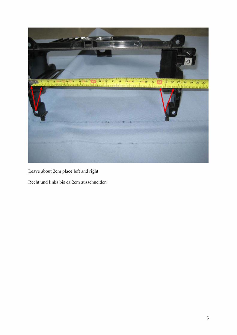
1: Remove all cables that the BEHR Air box is totally free to place the cutout template Place the template at the cross-borderline and rightside 4mm before the curb, newer versions also demount the temp-sensor (green cables) and also cutout the offset for the temp-sensor Alle Kabel auf dem Behr Kanal entfernen, die Schablone an der Knicklinie auflegen, rechts 4mm vor der vorstehenden Kante anlegen, mit neuer Version auch den Temp-Sensor herrausziehen (Grüne Kabel) und den Absatz für den Temp-Sensor herausschneiden. Anmerkung: Es muss nicht genau auf Millimenter geschnitten werden, der Bund des Kastens bietet Toleranzen beim ausschneiden 2: Declip all 4 clips for cleaning the box inside lateron and demounting the inner vent-flap-arm Die 4 Clipse entfernen, um später die Box innen zu reinigen und den Lüftungsklappenarm zu lösen
2
1
4mm

7
1: Declip the inner vent-arm, put it out and declip the outer motorized arm, use a screw driver for both Den inneren Lüftungsklappenarm lösen und herausnehmen, ebenfalls den äußeren Motorarm. Am besten vorsichtig mit einem Schraubenzieher aushebeln 2. Close the box again and outline the template for the cutout, best is you use a dremel-like device, also a very sharp cutter-knife will work. Be careful at that part Die Lüftungsbox wieder schließen, die Schablone auflegen und anzeichnen. Die Linie am besten mit einem dremelartigen Gerät auschneiden, bitte Vorsicht bei scharfen Cutter- Messern, wenn es nicht anders geht
1
8

9
1. Lift up the right air-flap at the buttom rotation center and put it out Die untere Drehachse der rechten Lüftungsklappe nach oben anheben und aushebeln 2. Next step liftup the air-tunnel plastic-connection and pull out the right air-flap, also be careful that the head doesn´t brake Nun den Lüftungskanal an der Verbindung anheben und die rechte Lüftungsklappe herausnehmen. Ebenfalls Vorsicht an dieser Stelle, damit der Hebelkopf nicht abbricht
1
2

10
1. Cut the flap with a dremel like above Die Lüftungsklappe wie oben teilen 2. Round the 5 racks at both sides with a rasp Die 5 Querstege an den Spitzen auf beiden Seiten mit einer Feile verrunden
1
2

11
Replace the flap again with the big screw driver, glue the cutted front-part with super-glue at the case. Clean the both gluing-sides with thinner and sand it locally, cause BEHR used vaseline for better flap movement Die K lappe w ieder m it e inem großen S chraubenzieher e inhebeln, de n a bgeschnittenen Fronteil mit Sekundenkleber am Gehäuse ankleben. Vorher die Klebeseiten mit Verdünnung reinigen und e twas a ufrauhen. BEHR benutzt V aseline f ür l eichtgängigeren Klappenmechanismus

12
Cut the vent-arm at the lift side 3,5cm at the left end with a dremel or saw, drill 2mm holes central at both sides Den Lüftungsklappenarm auf der linken Seite 3,5cm vor Ende durchtrennen, auf beiden Seiten zentrisch ein 2mm Loch bohren

13
Place-in the adapter plate and screw it Das Adapterblech einsetzen and an beiden Seiten verschrauben

14
Place-in the vent-arm again and test movement, connection should work again Den Verbindungsarm wieder einsetzen und Funktion testen

15
glue the sealing foil at the revolving border Das Dichtband umlaufend aufbringen

16
Place-in the new VA adapter- box, drill 2mm holes at 4 points and fix it Das Teilgehäuse einsetzen und an den 4 Punkten 2mm Bohrung anbringen, das Gehäuse verschrauben

17
Replace the radio holder and now drill 2mm holes through the cutted bolts through the dashboard (long drill) Den Radioträger wieder einsetzen und 2mm Löcher durch die Fixierbolzen durch das Armaturenbrett bohren, den Bohrer hier extra lang ansetzen, damit das Armaturenbrett keinen Schaden nimmt
18
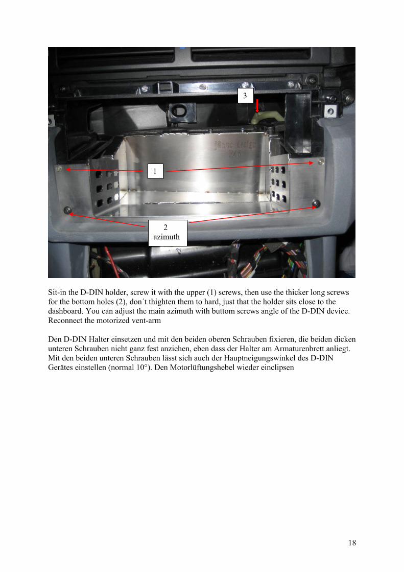
Sit-in the D-DIN holder, screw it with the upper (1) screws, then use the thicker long screws for the bottom holes (2), don´t thighten them to hard, just that the holder sits close to the dashboard. You can adjust the main azimuth with buttom screws angle of the D-DIN device. Reconnect the motorized vent-arm Den D-DIN Halter einsetzen und mit den beiden oberen Schrauben fixieren, die beiden dicken unteren Schrauben nicht ganz fest anziehen, eben dass der Halter am Armaturenbrett anliegt. Mit den beiden unteren Schrauben lässt sich auch der Hauptneigungswinkel des D-DIN Gerätes einstellen (normal 10°). Den Motorlüftungshebel wieder einclipsen
1
2 azimuth
3

19
Softly press the D-DIN bezel inside the dashboard that and fix it with the screws. Don´t screw them to endpoint, just that they are flush Die D-DIN Blende vorsichtig ins Armaturenbrett einfügen und mit den beiden Schrauben fixieren, diese bitte nicht endfest anziehen With the holder you have now various adjustment possibilities. Up/Down, In-Out inside the holder, also main azimuth on front of the holder Sie ha ben nun m it de m H alter ve rschiedene E instellmöglichkeiten. Auf+Ab, V or-Zurück zwischen Halter und Gerät, ebenso Hauptazimuthwinkel vorne am Halter.

20
Now descrew all again and put parts together l ike picture above, we are going to locate the ddin-device correctly now. Die Blende, den Gerätehalter und den Original- Funktionsträger wieder demontieren und eine Dummy- Vorrichtung bauen, um das Gerät richtig zu plazieren.

21
1. Mount the bezel now with both ear screws at the original radio-holder, be very careful at that part, cause the bezel is only fixed at two points (distance front surface to metal sheet at buttom border = 19mm, also see page 23) Die Blende nun von vorne an den Funktionsträger schrauben, bitte äußerst vorsichtig an dieser Stelle, die Blende ist nur an 2 Punkten fixiert (Abstand Blendenoberfläche zu Unterkante Gerätehalter = 19mm, siehe Abstandhalter seite 23) 2. Move the device now from the backside through the whole dummy-construction that it sits perfectly located inside the bezel cutout Das D-DIN Gerät nun von hinten durch die gesamte Dummy-Konstruktion schieben und auf perfekten Sitz innerhalb des Blenden-Ausschnittes prüfen 3. Use a marker for the 4 x M5 screws now, maybe use included washers if the screws may be too long ...very different depth, depends on what device you have. Screw now the mounting screws Mit einem Liner die Position der Schrauben markieren, evtl. die beigelegten Unterleg- scheiben benutzen.... verschiedene Gewindetiefen je nach Gerät. Diese nun anziehen
1
2
3
19mm

22
Position the device that it sits perfectly at all 4 corner, this will be the best location. Demount only the front bezel now, you can place-in the device + holder inside the dashboard again Das Gerät s o pos itionieren, da ss es a n a llen 4 Ecken bündi g a bschließt. D ie F rontblende wieder d emontieren un d das D DIN-Gerät mit s amt de m H alter w ieder ins D ashboard verschrauben, Kabel anschließen nicht vergessen !!

23
Beide beigefügten A bstandschrauben mit D istanzgummi e inschrauben und a uf c a. 10mm Kopfabstand einstellen, di e B lende aufsetzen und pr üfen. Eine ide ale E instellung is t gefunden, wenn die Blende umlaufend genau bündig und ohne Tiefenabsatz mit dem Cockpit abschließt Mount b oth distance s crews w ith gromets and place t hem about 10mm headspace to the ground sheet. Place-In the bezel. An ideal distance is found when the bezel buttomside closes perfectly to the dashboard
new till 10/2008

24
Falls die obere Deckblende auf der Blende sich aufspreitzt, von Modell zu Modell verschieden, bitte rückseitig etwas aussparen Dremel out the interior-bezel like shown above, if it seats up to the bezel and the gap is too big