Embed Size (px)
Citation preview
De
lta
So
l®
KS
www.resol.deThank you for buying a RESOL product.Please read this manual carefully in order to put this controller to the best possible use.
RESOL DeltaSol® KS
Mounting Connection Operation Fault finding
Manual
B
DeltaSol® KS
© R
ESO
L 06
047
delta
Sol_
ks.m
onen
.indd
| 2
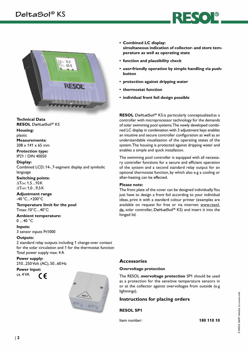
Technical Data RESOL DeltaSol® KSHousing: plastic Measurements: 208 x 141 x 65 mmProtection type: IP21 / DIN 40050Display: Combined LCD; 14-, 7-segment display and symbolic languageSwitching points: ∆TON: 1,5 ...10 K ∆TOFF: 1,0 ...9,5 KAdjustment range -40 °C...+200°CTemperature limit for the pool Tmax: 10°C ... 40°CAmbient temperature: 0 ... 40 °CInputs: 3 sensor inputs Pt1000Outputs: 2 standard relay outputs including 1 change-over contact for the solar circulation and 1 for the thermostat function Total power supply max. 4 APower supply: 210...250 Volt (AC), 50...60 HzPower input: ca. 4 VA
Accessories
Overvoltage protection
The RESOL overvoltage protection SP1 should be used as a protection for the sensitive temperature sensors in or at the collector against overvoltages from outside (e.g lightnings).
Instructions for placing orders
RESOL SP1 Item number: 180 110 10
• Combined LC display: simultaneous indication of collector- and store tem-perature as well as operating state
• function and plausibility check
• user-friendly operation by simple handling via push-button
• protection against dripping water
• thermostat function
• individual front foil design possible
RESOL DeltaSol® KS is particularly conceptualized as a controller with microprocessor technology for the demands of solar swimming pool systems. The newly developed combi-ned LC display in combination with 3 adjustment keys enables an intuitive and secure controller configuration as well as an understandable visualization of the operating states of the system. The housing is protected against dripping water and enables a simple and quick installation.
The swimming pool controller is equipped with all necessa-ry controller functions for a secure and efficient operation of the system and a second standard relay output for an optional thermostat function, by which also e.g a cooling or after-heating can be effected.
Please note:The front plate of the cover can be designed individually. You just have to design a front foil according to your individual ideas, print it with a standard colour printer (examples are available on request for free or via internet: www.resol.de, solar controller, DeltaSol® KS) and insert it into the hinged lid.
DeltaSol® KS©
RES
OL
0604
7 de
ltaSo
l_ks
.mon
en.in
dd
3 |
*
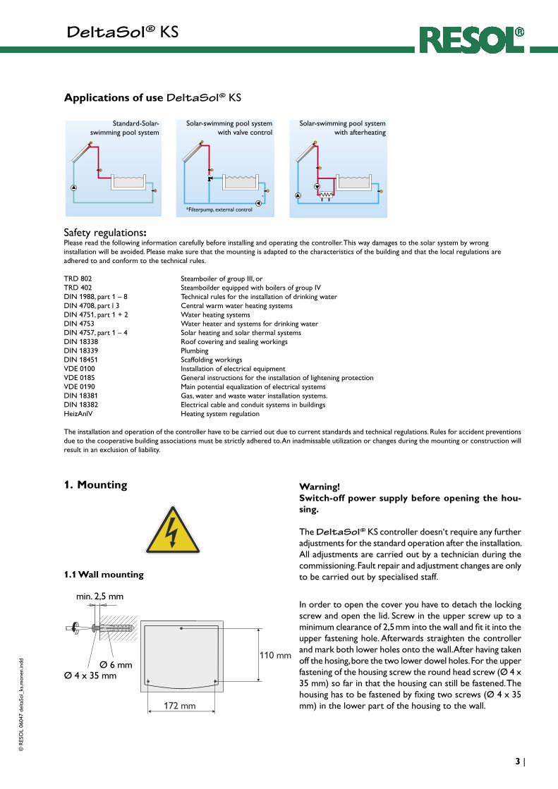
Safety regulations:Please read the following information carefully before installing and operating the controller. This way damages to the solar system by wronginstallation will be avoided. Please make sure that the mounting is adapted to the characteristics of the building and that the local regulations areadhered to and conform to the technical rules.
TRD 802 Steamboiler of group III, orTRD 402 Steamboilder equipped with boilers of group IVDIN 1988, part 1 – 8 Technical rules for the installation of drinking waterDIN 4708, part l 3 Central warm water heating systemsDIN 4751, part 1 + 2 Water heating systemsDIN 4753 Water heater and systems for drinking waterDIN 4757, part 1 – 4 Solar heating and solar thermal systemsDIN 18338 Roof covering and sealing workingsDIN 18339 PlumbingDIN 18451 Scaffolding workingsVDE 0100 Installation of electrical equipment VDE 0185 General instructions for the installation of lightening protectionVDE 0190 Main potential equalization of electrical systemsDIN 18381 Gas, water and waste water installation systems.DIN 18382 Electrical cable and conduit systems in buildings HeizAnlV Heating system regulation
The installation and operation of the controller have to be carried out due to current standards and technical regulations. Rules for accident preventions due to the cooperative building associations must be strictly adhered to. An inadmissable utilization or changes during the mounting or construction will result in an exclusion of liability.
1. Mounting
1.1 Wall mounting
Warning!Switch-off power supply before opening the hou-sing.
The DeltaSol® KS controller doesn‘t require any further adjustments for the standard operation after the installation. All adjustments are carried out by a technician during the commissioning. Fault repair and adjustment changes are only to be carried out by specialised staff.
In order to open the cover you have to detach the locking screw and open the lid. Screw in the upper screw up to a minimum clearance of 2,5 mm into the wall and fit it into the upper fastening hole. Afterwards straighten the controller and mark both lower holes onto the wall. After having taken off the hosing, bore the two lower dowel holes. For the upper fastening of the housing screw the round head screw (Ø 4 x 35 mm) so far in that the housing can still be fastened. The housing has to be fastened by fixing two screws (Ø 4 x 35 mm) in the lower part of the housing to the wall.
Applications of use DeltaSol® KS
Standard-Solar- swimming pool system
Solar-swimming pool system with valve control
Solar-swimming pool system with afterheating
*Filterpump, external control
DeltaSol® KS
© R
ESO
L 06
047
delta
Sol_
ks.m
onen
.indd
| 4
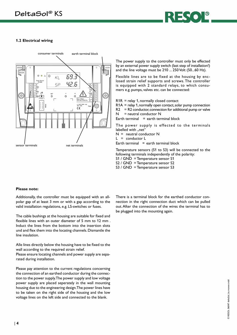
1.2 Electrical wiring
The power supply to the controller must only be effected by an external power supply switch (last step of installation!) and the line voltage must be 210 ... 250 Volt (50...60 Hz).
Flexible lines are to be fixed at the housing by enc-losed strain relief supports and screws. The controller is equipped with 2 standard relays, to which consu-mers e.g. pumps, valves etc. can be connected:
R1R = relay 1, normally closed contact R1A = relay 1, normally open contact, solar pump connection R2 = R2 conductor, connection for additional pump or valve N = neutral conductor N Earth terminal = earth terminal block
The power supply i s e f fected to the termina ls labelled with „net“ N = neutral conductor N L = conductor L Earth terminal = earth terminal block
Temperature sensors (S1 to S3) will be connected to the following terminals independently of the polarity: S1 / GND = Temperature sensor S1 S2 / GND = Temperature sensor S2 S3 / GND = Temperature sensor S3
sensor terminals
consumer terminals
net terminals
earth terminal block
Additionally, the controller must be equipped with an all-polar gap of at least 3 mm or with a gap according to the valid installation regulations, e.g. LS-switches or fuses.
The cable bushings at the housing are suitable for fixed and flexible lines with an outer diameter of 5 mm to 12 mm . Induct the lines from the bottom into the insertion slots und and flex them into the locating channels. Dismantle the line insulation.
Alle lines directly below the housing have to be fixed to the wall according to the required strain relief. Please ensure locating channels and power supply are sepa-rated during installation.
Please pay attention to the current regulations concerning the connection of an earthed conductor during the connec-tion to the power supply. The power supply and low voltage power supply are placed seperately in the wall mounting housing due to the engineering design. The power lines have to be taken on the right side of the housing and the low voltage lines on the left side and connected to the blank.
There is a terminal block for the earthed conductor con-nection in the right connection duct which can be pulled out. After the connection of the wires the terminal has to be plugged into the mounting again.
Please note:

DeltaSol® KS©
RES
OL
0604
7 de
ltaSo
l_ks
.mon
en.in
dd
5 |
2. Sensor types
FK... : collector sensor FR... : reference sensor (store sensor)
The sensors used for the DeltaSol® KS controller are precision temperature sensors type PT1000 (FKP and FRP).
The arrangement of the sensors is of great importance to the total efficiency of the controller. The collector tempera-ture should be measured at the upper part of the collector. In stores with integral heat exchangers, the sensor with an immersion sleeve must be mounted directly at the up-per part of the heat exchanger. When using external heat exchangers, the sensor with an immersion sleeve must be fixed at the bottom of the store. For individual operation systems, our product range contains 3 different types of sensors: sensors with immersion sleeves, flatscrew sensors and cylindrical clip-on sensors. The FK and FR sensor types have the same electrical features and are available in the same models. They differ only in the type of the connecting cable:
Please note:In order to avoid damage from overvoltage at the collector (e.g. by lightening), it is highly recommendend to use the RESOL SP1 overvoltage protection.
FK: 1,5 m weather- and temperature resistant sili-cone cable for temperatures between -50 °C ... +180 °C, mostly utilized for collectors.
FR: 2,5 m PVC cable for tempertures between -5 °C ... +80 °C, mostly utilized for stores.
Make sure that all electrical works are carried out according to the relevant local and IEE-regulations. The sensor cables carry low voltages and they must not run together in a cable conduit with cables carrying voltages higher than 50 Volts. When using longer cables or cable conduits, please use screened cables. The sensor cables can be lengthened up to 100 m, but the cross section must be 1,5 mm² (or 0,75 mm² up to a cable length of 50m); only screened cables should be used. The sensors must not be in direct contact with water, please always use immersion sleeves.

DeltaSol® KS
© R
ESO
L 06
047
delta
Sol_
ks.m
onen
.indd
| 6
3.1 Equipment overview
3. Operation
3.2 Operation mode switch
operating control lampcombined LCD
earthed conductor terminal block
consumer terminal
net terminal
fuse
operation mode switch
sensor terminals
cover plug screw cable inductionadjustment keys
The operation mode switch can be found at the position marked with and enables following adjustments:
0 Relay 1 switched off, symbol is displayed, ope-rating control lamp flashes red
Auto Automatic controller operation for relay out-puts
I Relay R1 switched on, continuous operation, symbols and are being displayed, operating control lamp flashes green.
3.3 Adjustment keys
The controller can be adjusted to the system by means of the adjustment parameters. Usually, the solar swimming pool system can be run efficiently by the preadjusted values of the factory setting. The three adjustment keys are accessible after opening the cover. By pressing the <+> key the indication channels will be shown one after another and then the adjusment chan-nels will follow (see also page 7). In order to acquire these channels, press the <+> key in channel PH for 2 sec.. After having accessed the parameter that is to be changed, the
parameter will be activated by means of the <SET> key and the symbol <SET> will be displayed. Now you the required parameter value can be adjusted with the <+> key or <-> . The adjustment has to be confirmed and finalized by pushing the <SET> key once again.
In order to get back to the standard mode, press the <-> key several times. The controller has a built-in time-out-function, so that after 2 min of not having pressed any key the standard mode will be displayed.

DeltaSol® KS©
RES
OL
0604
7 de
ltaSo
l_ks
.mon
en.in
dd
7 |
3.4 Controller parameter and indication channels
3.5 Function description
Important notice:By means of a internal locking mechanism, it is only possible to adjust such pairs of values, for which the switch-on tem-perature differential DE is at least by 0,5 K bigger than the switch-off temperature differential DA.
The RESOL DeltaSol® KS controller controlls the tem-perature diffence between the absorber and return flow pool(S1 and S2) temperature and compares this difference to a predetermined switch-on temperature differential ∆TON (DE). The controller siwtches ON, if the measured tempera-ture difference ∆T is bigger than or equals the value pread-justed in the DE channel. Symbols and are displayed and the operating control lamp flashes green (phase 0).
If the switch-off temperature differential ∆Toff (DA) between the absorber and the return flow pool (S1 and S2) is under-run, the R1 relay will remain switched on for the duration of the preadjusted switch-on delay (VA). Symbols and
(flashing) are displayed and the operating control lamp flashes green (phase 1).
If the temperature differential between the feed and return flow (S3 and S2) of the pool after the preadjusted switch-off temperature delay is bigger than the switch-off temperature differential, relay R1 will remain switched on. Symbols and are displayed and the operating control lamp flashes green (phase 2).
Channel Indication Value group Min. Max. Factory setting Unit SpecificationAB absorber temperature measured value - - - °C current absorber temperature
RL return flow temperature measured value - - - °C current return flow temperature
VL feed flow temperature measured value - - - °C current feed flow temperature
VZ delay time check value - - - min current active delay time, see also page 8 (control phases)
PH control phase check value - - - - -
DE switch-on temperature differential
set value 1.5 10.0 6.0 K If the preadjusted temperature difference is exceeded, R1 is switched on.
DA switch-off temperature differential
set value 1.0 9.5 4.0 K If the preadjusted temperature difference is underrun, R1 is switched off.
MX pool maximum tempe-rature
set value 10.0 40.0 30.0 °C If the preadjusted temperature is exceeded, R1 is switched off.
VA switch-off delay set value 0.1 15.0 1.0 min switch-on follow-up time, see also page 8 (control phases).
VE switch-on delay set value 0,1 15.0 1.0 min switch- on delay, see also page 8 (control phases).
TE thermostat switch-on temperature
set value 0.0 95.0 40.0 °C see chapter 3.11
TA thermostat switch-off temperature
set value 0.0 95.0 40.0 °C see chapter 3.11
PG program number indication -
VN version-number indication -
If the switch-off temperature differential between the feed and return flow of the pool is underrun, relay R1 is swit-ched off. The following switch-on delay (VE) prevents a too frequent switch-on of the system (clocking) and enables a sufficient re-heating of the absorber. Symbol (flashing) is displayed and the operating control lamp flashes green (phase 3).
The currently active control phase (PH) and the already terminated appropriate delay time (VA, VE) will be displayed as check values in channels PH and VZ .
DeltaSol® KS
© R
ESO
L 06
047
delta
Sol_
ks.m
onen
.indd
| 8
3.6 Maximum pool temperature (MX)
If the set maximum temperature at the return flow tem-perature sensor is exceeded, a further heating of the pool water is prevented by means of the absorber. Not until the return flow temperature falls below a value of1 K below the for MX set temperature, relay R1 will be switched on again for a further pool water heating The maximum pool tempe-rature is preadjusted to a factory setting of 3 0 °C.
If the maximum pool temperature is exceeded, symbol is displayed,the operating control lamp flashes green.
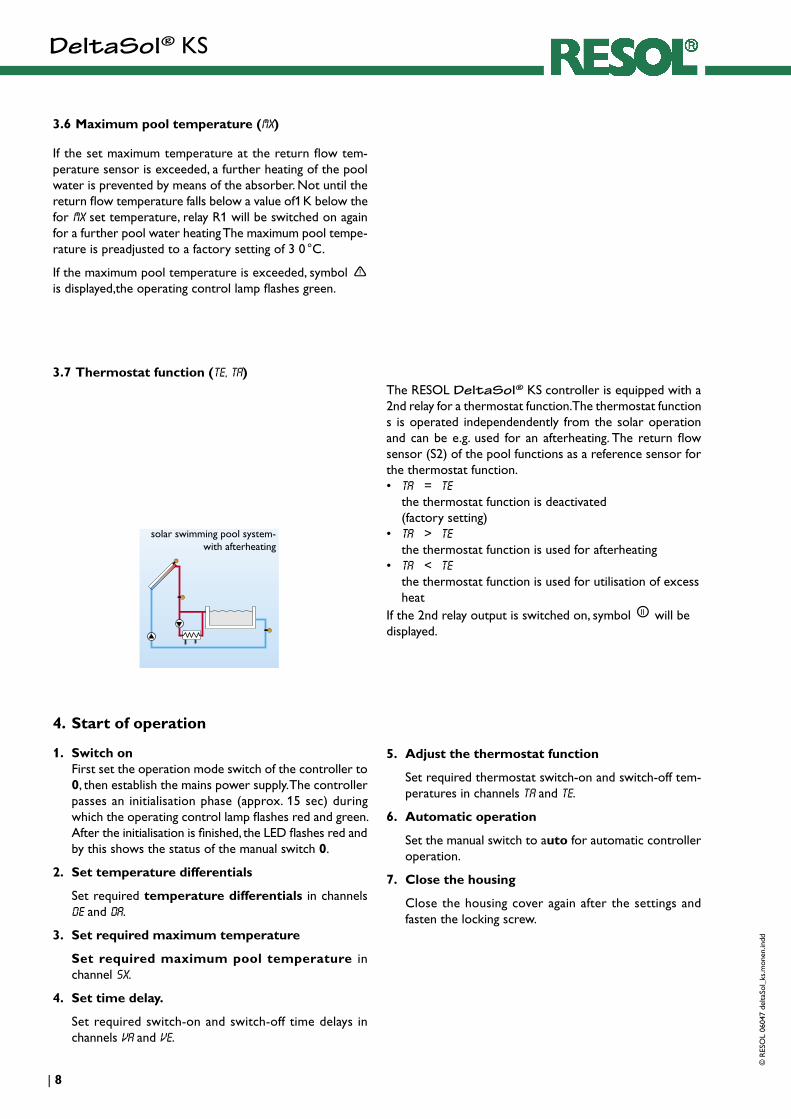
The RESOL DeltaSol® KS controller is equipped with a 2nd relay for a thermostat function. The thermostat function s is operated independendently from the solar operation and can be e.g. used for an afterheating. The return flow sensor (S2) of the pool functions as a reference sensor for the thermostat function.• ta = te
the thermostat function is deactivated (factory setting)
• TA > TE the thermostat function is used for afterheating
• TA < TE the thermostat function is used for utilisation of excess heat
If the 2nd relay output is switched on, symbol will be displayed.
3.7 Thermostat function (te, Ta)
4. Start of operation
1. Switch on First set the operation mode switch of the controller to 0, then establish the mains power supply. The controller passes an initialisation phase (approx. 15 sec) during which the operating control lamp flashes red and green. After the initialisation is finished, the LED flashes red and by this shows the status of the manual switch 0.
2. Set temperature differentials
Set required temperature differentials in channels DE and DA.
3. Set required maximum temperature
Set required maximum pool temperature in channel SX.
4. Set time delay.
Set required switch-on and switch-off time delays in channels VA and VE.
5. Adjust the thermostat function
Set required thermostat switch-on and switch-off tem-peratures in channels tA and tE.
6. Automatic operation
Set the manual switch to auto for automatic controller operation.
7. Close the housing
Close the housing cover again after the settings and fasten the locking screw.
solar swimming pool system-with afterheating
DeltaSol® KS©
RES
OL
0604
7 de
ltaSo
l_ks
.mon
en.in
dd
9 |
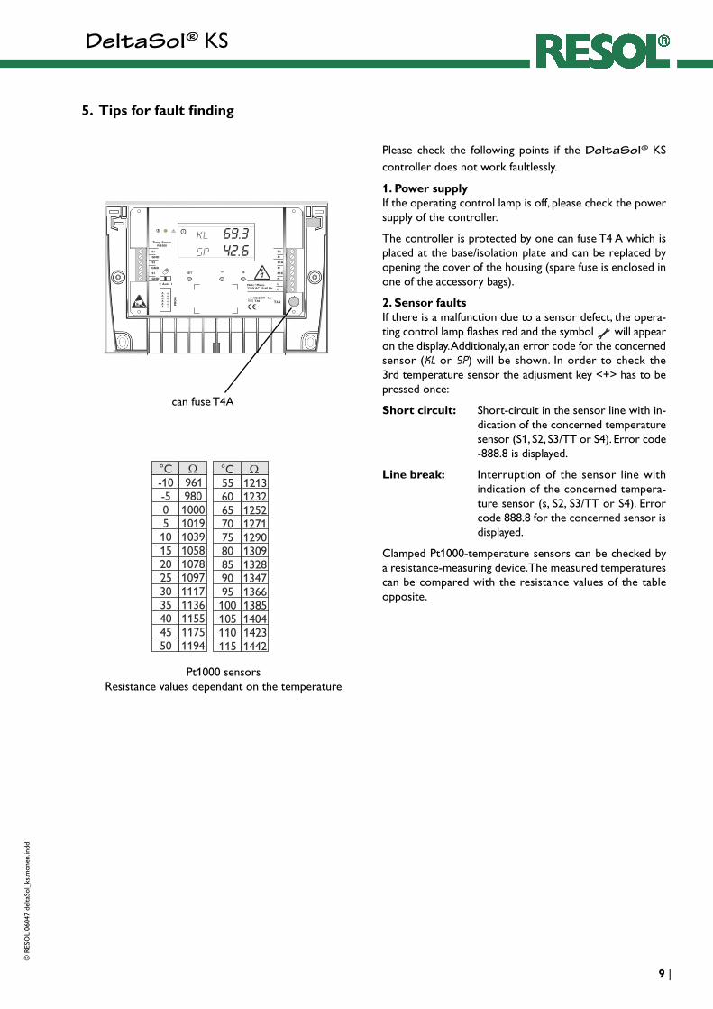
5. Tips for fault finding
Please check the following points if the DeltaSol® KS controller does not work faultlessly.
1. Power supply If the operating control lamp is off, please check the power supply of the controller.
The controller is protected by one can fuse T4 A which is placed at the base/isolation plate and can be replaced by opening the cover of the housing (spare fuse is enclosed in one of the accessory bags).
2. Sensor faults If there is a malfunction due to a sensor defect, the opera-ting control lamp flashes red and the symbol will appear on the display. Additionaly, an error code for the concerned sensor (KL or SP) will be shown. In order to check the 3rd temperature sensor the adjusment key <+> has to be pressed once:
Short circuit: Short-circuit in the sensor line with in-dication of the concerned temperature sensor (S1, S2, S3/TT or S4). Error code -888.8 is displayed.
Line break: Interruption of the sensor line with indication of the concerned tempera-ture sensor (s, S2, S3/TT or S4). Error code 888.8 for the concerned sensor is displayed.
Clamped Pt1000-temperature sensors can be checked by a resistance-measuring device. The measured temperatures can be compared with the resistance values of the table opposite.
Pt1000 sensorsResistance values dependant on the temperature
can fuse T4A
DeltaSol® KS
© R
ESO
L 06
047
delta
Sol_
ks.m
onen
.indd
| 10
S1
S2
S3
R1
R1A/R
S1
S3
S2
6. Application examples
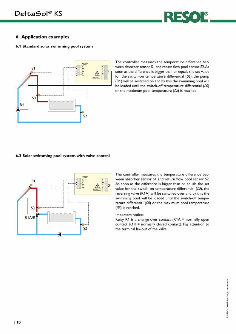
6.1 Standard solar swimming pool system
6.2 Solar swimming pool system with valve control
The controller measures the temperature difference bet-ween absorber sensor S1 and return flow pool sensor S2. As soon as the difference is bigger than or equals the set value for the switch-on temperature differential (DE), the pump (R1) will be switched on and by this the swimming pool will be loaded until the switch-off temperature differential (DA) or the maximum pool temperature (MX) is reached.
The controller measures the temperature difference bet-ween absorber sensor S1 and return flow pool sensor S2. As soon as the difference is bigger than or equals the set value for the switch-on temperature differential (DE), the reversing valve (R1A) will be switched over and by this the swimming pool will be loaded until the switch-off tempe-rature differential (DA) or the maximum pool temperature (MX) is reached.
Important notice: Relay R1 is a change-over contact (R1A = normally open contact, R1R = normally closed contact). Pay attention to the terminal lay-out of the valve.
DeltaSol® KS©
RES
OL
0604
7 de
ltaSo
l_ks
.mon
en.in
dd
11 |
S1
R1 R2
S2
S3
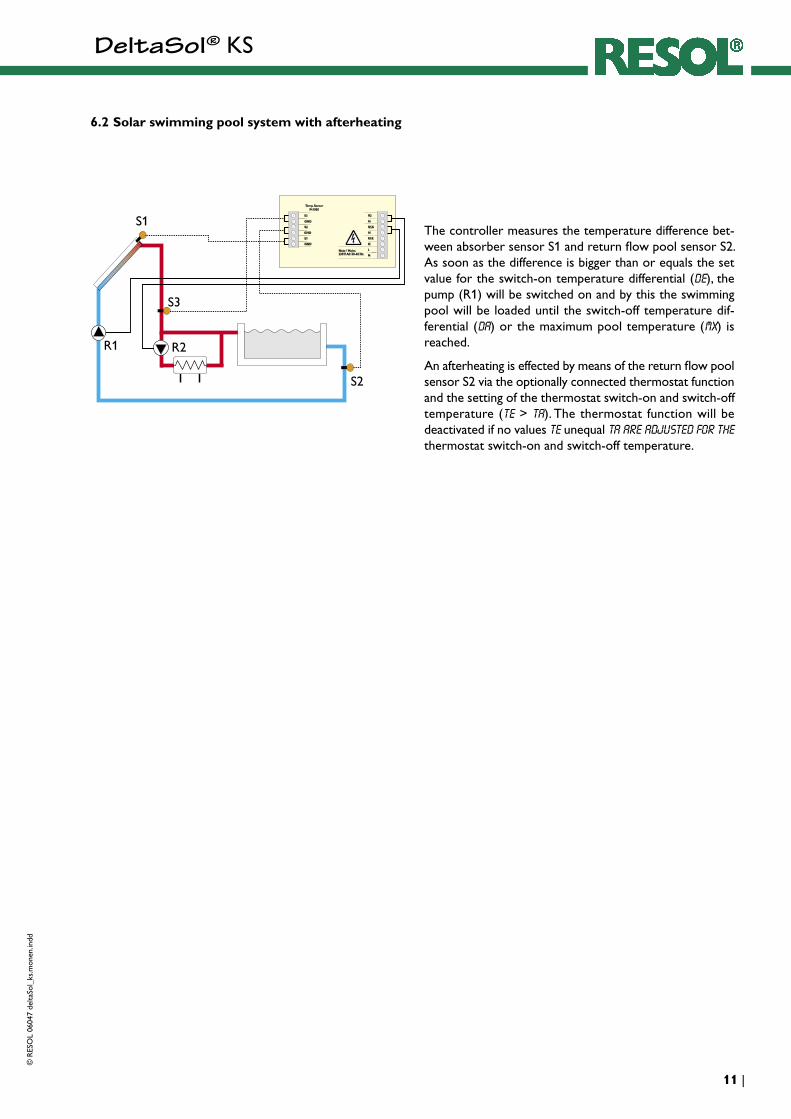
6.2 Solar swimming pool system with afterheating
The controller measures the temperature difference bet-ween absorber sensor S1 and return flow pool sensor S2. As soon as the difference is bigger than or equals the set value for the switch-on temperature differential (DE), the pump (R1) will be switched on and by this the swimming pool will be loaded until the switch-off temperature dif-ferential (DA) or the maximum pool temperature (MX) is reached.
An afterheating is effected by means of the return flow pool sensor S2 via the optionally connected thermostat function and the setting of the thermostat switch-on and switch-off temperature (Te > Ta). The thermostat function will be deactivated if no values Te unequal Ta are adjusted for the thermostat switch-on and switch-off temperature.
DeltaSol® KS
© R
ESO
L 06
047
delta
Sol_
ks.m
onen
.indd
| 12
Your specialist dealer:
NotesDesign and specifications are subject to change without notice.Illustrations may differ slightly from production models.
RESOL - Elektronische Regelungen GmbH
Heiskampstraße 10 D - 45527 Hattingen
Tel.: +49 (0) 23 24 / 96 48 - 0 Fax: +49 (0) 23 24 / 96 48 - 55
www.resol.de [email protected]