Embed Size (px)
Citation preview
Mounting and Cable Routing Procedures for Dell™ Digital KVM’s (1082DS, 2162DS, 4322DS)
A Dell™ Technical White Paper
Dell™ │ Datacenter Infrastructure Engineering
By Daniel Whittaker and Jose L. Flores
August 2010

Mounting and Cable Routing Procedures for Dell™ Digital KVM’s (1082DS, 2162DS, 4322DS)
Page ii
THIS WHITE PAPER IS FOR INFORMATIONAL PURPOSES ONLY, AND MAY CONTAIN TYPOGRAPHICAL
ERRORS AND TECHNICAL INACCURACIES. THE CONTENT IS PROVIDED AS IS, WITHOUT EXPRESS
OR IMPLIED WARRANTIES OF ANY KIND.
© 2010 Dell Inc. All rights reserved. Reproduction of this material in any manner whatsoever without
the express written permission of Dell Inc. is strictly forbidden. For more information, contact Dell.
Dell, the DELL logo, the DELL badge, and PowerEdge are trademarks of Dell Inc.
Mounting and Cable Routing Procedures for Dell™ Digital KVM’s (1082DS, 2162DS, 4322DS)
Page 1
Contents Introduction ............................................................................................................................................................... 3
Section 1: 0U Mounting Locations ............................................................................................................................. 3
1.1 Supported Locations in the PowerEdge™ 4210 and 2410 ........................................................................... 3
1.2 Supported Locations in the PowerEdge™ 4820, 4220, and 2420 ................................................................ 5
Section 2: 1U Mounting Locations ............................................................................................................................. 6
2.1 Mounting the KVM in the Front of the Rack ................................................................................................ 6
2.2 Mounting the KVM in the Back of the Rack ................................................................................................. 6
Section 3: Cabling a KVM ........................................................................................................................................... 6
3.1 Four Post Front of Rack Cabling ................................................................................................................... 7
3.1.1 Connecting the Cables to the KVM .......................................................................................................... 7
3.1.2 Routing the Power Cables and Data Cables ............................................................................................. 7
3.2 Two Post Flush Mount Cabling ..................................................................................................................... 8
3.2.1 Connecting the Cables to the KVM .......................................................................................................... 8
3.2.2 Routing the Power Cables and Data Cables ............................................................................................. 9
Section 4: KVM Resolution Information .................................................................................................................. 10
4.1 Dell™ KVM Resolution by Model ................................................................................................................ 10
4.2 Server Interface Pod Matrix ....................................................................................................................... 11
Figures and Tables
Figure 1: KVM Mounted on Vertical Member ........................................................................................................ 4
Figure 2: KVM Mounted on Horizontal Member .................................................................................................. 5
Figure 3: KVM Mounted on Vertical Member ........................................................................................................ 6
Figure 4: Four Post Rack: System and Cables Installed....................................................................................... 7
Figure 5: Four Post Rack: Routing Power and Data Cables ............................................................................... 8
Figure 6: Removable portion of rail ........................................................................................................................ 8
Figure 7: Two Post Rack: System and Cables Installed ....................................................................................... 9
Figure 8: Two post Rack: Routing Power and Data Cables ................................................................................ 9
Figure 9: Two post Rack: Routing Power and Data Cables (Optional Tie) .................................................... 10
Table 1: Rail Adjustment Range ............................................................................................................................... 3
Table 2: Dell™ KVM Resolution by Model ........................................................................................................... 10
Table 3: Server Interface Pod Matrix 4:3 Resolutions ........................................................................................ 11
Table 4: Server Interface Pod Matrix 16:10 Resolutions .................................................................................... 11
Mounting and Cable Routing Procedures for Dell™ Digital KVM’s (1082DS, 2162DS, 4322DS)
Page 2

Mounting and Cable Routing Procedures for Dell™ Digital KVM’s (1082DS, 2162DS, 4322DS)
Page 3
Introduction This white paper covers recommended mounting and cable routing procedures for Dell™ Digital
KVMs (1082DS, 2162DS, 4322DS) in the following rack enclosures:
PowerEdge™ 4210
PowerEdge 2410
PowerEdge 4820
PowerEdge 4220
PowerEdge 2420
The adjustment range for the rails provided with the digital KVMs for third party racks is shown in Table
1. Rail Adjustability Range represents the allowable distance between the outside-facing surfaces of
the front and rear mounting posts of the rack
Table 1: Rail Adjustment Range
Min (mm) Max (mm)
Square Hole 470 770
Round Hole 456 763
Threaded Hole 462 794
For guidelines on how to route cables within the rack, refer to the Dell Best Practices Guide for Rack Enclosure white paper.
Section 1: 0U Mounting Locations This section details the locations in the Dell PowerEdge rack enclosures where the KVMs can be
installed, as shipped by Dell™.
Please note the maximum ambient inlet temperature for the digital KVMs is 50 degrees C. In the
event that your rack temperature exceeds this value at the air inlet of the KVM, mount the digital KVM
in front of the rack (Section 2.1). The air inlet for the KVM is located on the non-port side, and the air
exhaust is located on the port side.
Follow the instructions contained in the Rack Installation Guide to install the KVM into the 0U bracket.
All illustrations in the following sections were created using a KVM 4322DS, however all the
information is applicable to the 1082DS and 2162DS.
1.1 Supported Locations in the PowerEdge™ 4210 and 2410 The PowerEdge 4210 and 2410 racks support mounting the KVM to the vertical and horizontal
members of the rack. The PowerEdge 4210 supports mounting four digital KVMs on the vertical
members, two on the left side, top and bottom, and two on the right side, top and bottom. The
PowerEdge 4210 also supports mounting two Digital KVMs on the horizontal members, one on the left
side and one on the right side. The PowerEdge 2410 supports mounting two digital KVMs on the
vertical members, one on the left side and one on the right side. The PowerEdge 2410 also supports
mounting two Digital KVMs on the horizontal members, one on the left side and one on the right side.

Mounting and Cable Routing Procedures for Dell™ Digital KVM’s (1082DS, 2162DS, 4322DS)
Page 4
Please note that installation of the KVM where the ports face the ground is an unsupported
orientation, and can cause damage to the KVM.
See Figures 1 and 2 for the supported locations to mount the Digital KVM in the aforementioned racks.
Figure 1: KVM Mounted on Vertical Member
PowerEdge 2410 Vertical PowerEdge 4210 Vertical Top
Mounting and Cable Routing Procedures for Dell™ Digital KVM’s (1082DS, 2162DS, 4322DS)
Page 5
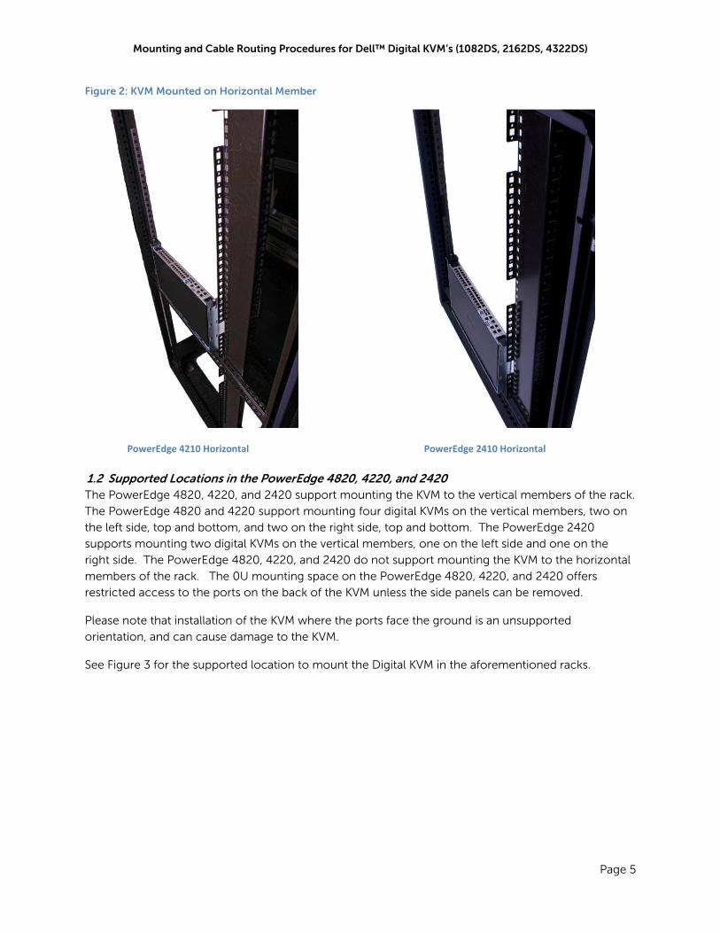
Figure 2: KVM Mounted on Horizontal Member
1.2 Supported Locations in the PowerEdge 4820, 4220, and 2420 The PowerEdge 4820, 4220, and 2420 support mounting the KVM to the vertical members of the rack.
The PowerEdge 4820 and 4220 support mounting four digital KVMs on the vertical members, two on
the left side, top and bottom, and two on the right side, top and bottom. The PowerEdge 2420
supports mounting two digital KVMs on the vertical members, one on the left side and one on the
right side. The PowerEdge 4820, 4220, and 2420 do not support mounting the KVM to the horizontal
members of the rack. The 0U mounting space on the PowerEdge 4820, 4220, and 2420 offers
restricted access to the ports on the back of the KVM unless the side panels can be removed.
Please note that installation of the KVM where the ports face the ground is an unsupported
orientation, and can cause damage to the KVM.
See Figure 3 for the supported location to mount the Digital KVM in the aforementioned racks.
PowerEdge 2410 Horizontal PowerEdge 4210 Horizontal
Mounting and Cable Routing Procedures for Dell™ Digital KVM’s (1082DS, 2162DS, 4322DS)
Page 6
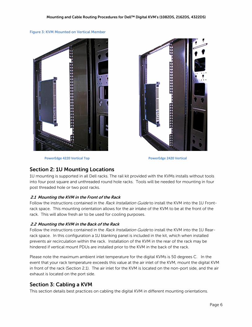
Figure 3: KVM Mounted on Vertical Member
Section 2: 1U Mounting Locations 1U mounting is supported in all Dell racks. The rail kit provided with the KVMs installs without tools
into four post square and unthreaded round hole racks. Tools will be needed for mounting in four
post threaded hole or two post racks.
2.1 Mounting the KVM in the Front of the Rack Follow the instructions contained in the Rack Installation Guide to install the KVM into the 1U Front-
rack space. This mounting orientation allows for the air intake of the KVM to be at the front of the
rack. This will allow fresh air to be used for cooling purposes.
2.2 Mounting the KVM in the Back of the Rack Follow the instructions contained in the Rack Installation Guide to install the KVM into the 1U Rear-
rack space. In this configuration a 1U blanking panel is included in the kit, which when installed
prevents air recirculation within the rack. Installation of the KVM in the rear of the rack may be
hindered if vertical mount PDUs are installed prior to the KVM in the back of the rack.
Please note the maximum ambient inlet temperature for the digital KVMs is 50 degrees C. In the
event that your rack temperature exceeds this value at the air inlet of the KVM, mount the digital KVM
in front of the rack (Section 2.1). The air inlet for the KVM is located on the non-port side, and the air
exhaust is located on the port side.
Section 3: Cabling a KVM This section details best practices on cabling the digital KVM in different mounting orientations.
PowerEdge 2420 Vertical PowerEdge 4220 Vertical Top
Mounting and Cable Routing Procedures for Dell™ Digital KVM’s (1082DS, 2162DS, 4322DS)
Page 7
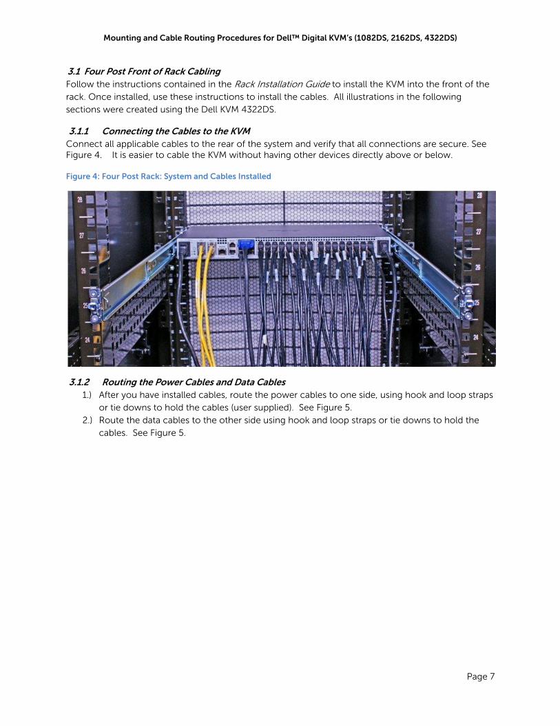
3.1 Four Post Front of Rack Cabling Follow the instructions contained in the Rack Installation Guide to install the KVM into the front of the
rack. Once installed, use these instructions to install the cables. All illustrations in the following
sections were created using the Dell KVM 4322DS.
3.1.1 Connecting the Cables to the KVM Connect all applicable cables to the rear of the system and verify that all connections are secure. See Figure 4. It is easier to cable the KVM without having other devices directly above or below. Figure 4: Four Post Rack: System and Cables Installed
3.1.2 Routing the Power Cables and Data Cables 1.) After you have installed cables, route the power cables to one side, using hook and loop straps
or tie downs to hold the cables (user supplied). See Figure 5.
2.) Route the data cables to the other side using hook and loop straps or tie downs to hold the
cables. See Figure 5.

Mounting and Cable Routing Procedures for Dell™ Digital KVM’s (1082DS, 2162DS, 4322DS)
Page 8
Figure 5: Four Post Rack: Routing Power and Data Cables
3.2 Two Post Flush Mount Cabling Follow the instructions contained in the Rack Installation Guide to install the KVM flush mount into the
two post rack. Once installed, use these instructions to install the cables. All illustrations in the
following sections were created using the Dell KVM 4322DS.
3.2.1 Connecting the Cables to the KVM Connect all applicable cables to the rear of the system and verify that all connections are secure. See Figure 7. Note that the back adjustable portion of the rail has been removed to allow access to the tie down holes used to retain the cables. See Figure 6 (front and back view of the removable portion of the rail). Figure 6: Removable portion of rail
Mounting and Cable Routing Procedures for Dell™ Digital KVM’s (1082DS, 2162DS, 4322DS)
Page 9
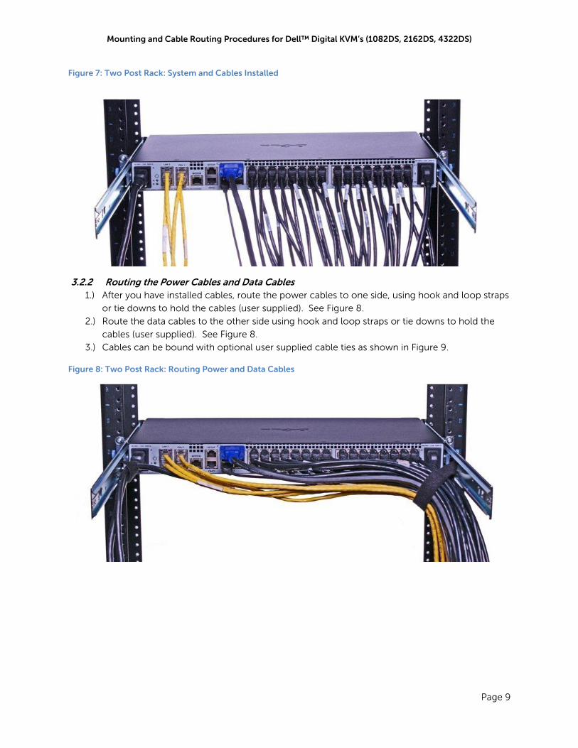
Figure 7: Two Post Rack: System and Cables Installed
3.2.2 Routing the Power Cables and Data Cables 1.) After you have installed cables, route the power cables to one side, using hook and loop straps
or tie downs to hold the cables (user supplied). See Figure 8.
2.) Route the data cables to the other side using hook and loop straps or tie downs to hold the
cables (user supplied). See Figure 8.
3.) Cables can be bound with optional user supplied cable ties as shown in Figure 9.
Figure 8: Two Post Rack: Routing Power and Data Cables

Mounting and Cable Routing Procedures for Dell™ Digital KVM’s (1082DS, 2162DS, 4322DS)
Page 10
Figure 9: Two Post Rack: Routing Power and Data Cables (Optional Tie)
Section 4: KVM Resolution Information
4.1 Dell KVM Resolution by Model Table 2 below shows the resolutions supported by Dell KVM model. The local port is the video port on
the back of the KVM that plugs into a monitor. The digitizer is the video sent over IP.
Acronyms:
Virtual Media (VM)
Common Access Card (CAC)
Table 2: Dell KVM Resolution by Model
Model
Local Port Digitizer VM Support
CAC Support Max 4:3 Max 16:10 Max 4:3 Max 16:10
180AS 1600x1200 N/A N/A N/A N N
2160AS 1600x1200 N/A N/A N/A N N
2161DS‐2 1600x1200 N/A 1024x768+ N/A Y N
4161DS 1600x1200 N/A 1024x768+ N/A Y N
2321DS 1600x1200 N/A 1024x768+ N/A Y N
1082DS 1600x1200 1680x1080 1600x1200 1680x1050 Y Y
2162DS 1600x1200 1680x1080 1600x1200 1680x1050 Y Y
4322DS 1600x1200 1680x1080 1600x1200 1680x1050 Y Y
+ The digitizer is capable up to 1024x768 un-scaled (although it can accept up to 1280x1024, which
will be scaled down to 1024x768)
Mounting and Cable Routing Procedures for Dell™ Digital KVM’s (1082DS, 2162DS, 4322DS)
Page 11
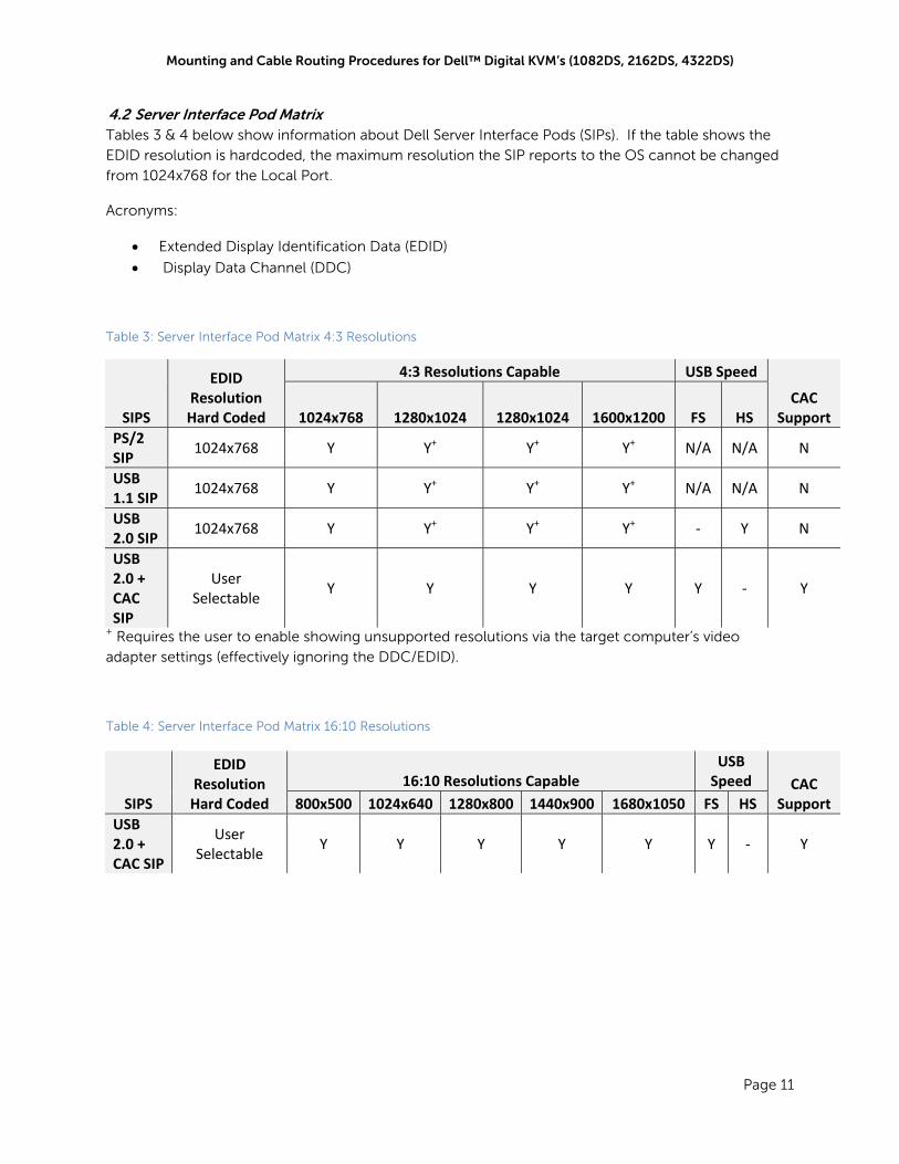
4.2 Server Interface Pod Matrix Tables 3 & 4 below show information about Dell Server Interface Pods (SIPs). If the table shows the
EDID resolution is hardcoded, the maximum resolution the SIP reports to the OS cannot be changed
from 1024x768 for the Local Port.
Acronyms:
Extended Display Identification Data (EDID)
Display Data Channel (DDC)
Table 3: Server Interface Pod Matrix 4:3 Resolutions
SIPS
EDID Resolution Hard Coded
4:3 Resolutions Capable USB Speed
CAC Support 1024x768 1280x1024 1280x1024 1600x1200 FS HS
PS/2 SIP
1024x768 Y Y+ Y+ Y+ N/A N/A N
USB 1.1 SIP
1024x768 Y Y+ Y+ Y+ N/A N/A N
USB 2.0 SIP
1024x768 Y Y+ Y+ Y+ ‐ Y N
USB 2.0 + CAC SIP
User Selectable
Y Y Y Y Y ‐ Y
+ Requires the user to enable showing unsupported resolutions via the target computer’s video
adapter settings (effectively ignoring the DDC/EDID).
Table 4: Server Interface Pod Matrix 16:10 Resolutions
SIPS
EDID Resolution Hard Coded
16:10 Resolutions Capable USB Speed CAC
Support 800x500 1024x640 1280x800 1440x900 1680x1050 FS HS
USB 2.0 + CAC SIP
User Selectable
Y Y Y Y Y Y ‐ Y


![The Garden District Collectionpdf.lowes.com/installationguides/877697005270_install.pdf · Feed the mounting cable through the hiding plate, then attach mounting cable [a] to the](https://img.dokumen.tips/doc/110x75/60194495c3117421615e8c7c/the-garden-district-feed-the-mounting-cable-through-the-hiding-plate-then-attach.jpg)