Embed Size (px)
Citation preview
MOTOROLA DIGITAL SIGNAL PROCESSINGDEVELOPMENT SOFTWARE
MOTOROLA DSPASSEMBLER REFERENCE MANUAL
Specification and information herein are subject to change without notice. Motorola re-serves the right to make changes without further notice to any products described in thisdocument to improve reliability, function, or design. Motorola does not assume any liabilityarising out of the application or use of any product or circuit described herein, neither doesit convey any license under its patent rights or the rights of others. Motorola is a registeredtrademark of Motorola, Inc. Motorola, Inc. is an Equal Employment/Affirmative Action Em-ployer.
This manual documents the assembler as of version 5.3.2 of the software.
© Copyright Motorola, Inc. 1994. All rights reserved.
ASM56000, SIM56000, ASM96000, SIM96000, ASM56100, and SIM56100 are trade-marks of Motorola.
MS-DOS and Windows are trademarks of Microsoft Corporation.
Sun-4 and SunOS are trademarks of Sun Microsystems, Inc.
Macintosh and MPW are trademarks of Apple Computer.
PREFACE
MOTOROLA DSP ASSEMBLER REFERENCE MANUAL iii
Notation
The notational conventions used in this manual are:
DIRECTIVE
All assembler mnemonics and directives are shown in bold upper case to highlightthem. However, the assembler will recognize both upper and lower case for mne-monics and directives.
{ }
Contains a list of elements or directives, one of which must be selected. Eachchoice will be separated by a vertical bar. For example, {
R
I
L
} indicates that either
R
or
L
must be selected.
[ ]
Contains one or more optional elements. If more than one optional element isshown, the required element separators are indicated. All elements outside of theangle brackets (< >) must be specified as they appear. For example, the syntacti-cal element [<number>,] requires the comma to be specified if the optional element<number> is selected.
Preface
iv DSP ASSEMBLER REFERENCE MANUAL MOTOROLA
Preface
< >
The element names are printed in lower case and contained in angle brackets.Some common elements used to describe directives are:
<comment> A statement comment<label> A statement label<expr> or An assembler expression<expression><number> A numeric constant<string> A string of ASCII characters enclosed in quotes<delimiter> A delimiter character<option> An assembler option<sym> or An assembler symbol<symbol>
Supporting Publications
DSP56000 Family Manual. Motorola, Inc. 1992.
DSP96002 User’s Manual. Motorola, Inc. 1989.
DSP56100 Family Manual. Motorola, Inc. 1993.
Motorola DSP Simulator Reference Manual. Motorola, Inc. 1994.
Motorola DSP Linker/Librarian Reference Manual. Motorola, Inc. 1994.
MOTOROLA DSP ASSEMBLER REFERENCE MANUAL v
TABLE OF CONTENTS
Paragraph PageNumber Title Number
Preface
Chapter 1MOTOROLA DSP ASSEMBLER
1.1 INTRODUCTION . . . . . . . . . . . . . . . . . . . . . . . . . . . . . . . . . . . . . . . . . . . . . . 1
1.2 ASSEMBLY LANGUAGE . . . . . . . . . . . . . . . . . . . . . . . . . . . . . . . . . . . . . . . . 1
1.3 INSTALLING THE ASSEMBLER . . . . . . . . . . . . . . . . . . . . . . . . . . . . . . . . . . 1
1.4 RUNNING THE ASSEMBLER . . . . . . . . . . . . . . . . . . . . . . . . . . . . . . . . . . . . 1
1.5 ASSEMBLER PROCESSING . . . . . . . . . . . . . . . . . . . . . . . . . . . . . . . . . . . . . 9
1.6 DEFINITION OF TERMS . . . . . . . . . . . . . . . . . . . . . . . . . . . . . . . . . . . . . . . . 9
1.7 ASSEMBLER SUPPORT FOR DIGITAL SIGNAL PROCESSING . . . . . . . . 10
Chapter 2WRITING ASSEMBLY LANGUAGE PROGRAMS
2.1 INPUT FILE FORMAT . . . . . . . . . . . . . . . . . . . . . . . . . . . . . . . . . . . . . . . . . 13
2.2 SYMBOL NAMES . . . . . . . . . . . . . . . . . . . . . . . . . . . . . . . . . . . . . . . . . . . . . 13
2.3 STRINGS . . . . . . . . . . . . . . . . . . . . . . . . . . . . . . . . . . . . . . . . . . . . . . . . . . . 14
2.4 SOURCE STATEMENT FORMAT . . . . . . . . . . . . . . . . . . . . . . . . . . . . . . . . 14
2.4.1 Label Field . . . . . . . . . . . . . . . . . . . . . . . . . . . . . . . . . . . . . . . . . . . . . . . 15
2.4.2 Operation Field. . . . . . . . . . . . . . . . . . . . . . . . . . . . . . . . . . . . . . . . . . . . 16
2.4.3 Operand Field. . . . . . . . . . . . . . . . . . . . . . . . . . . . . . . . . . . . . . . . . . . . . 17
2.4.4 Operation 2 Field . . . . . . . . . . . . . . . . . . . . . . . . . . . . . . . . . . . . . . . . . . 17
2.4.5 Operand 2 Field . . . . . . . . . . . . . . . . . . . . . . . . . . . . . . . . . . . . . . . . . . . 17
2.4.6 Data Transfer Fields. . . . . . . . . . . . . . . . . . . . . . . . . . . . . . . . . . . . . . . . 17
2.4.7 Comment Field . . . . . . . . . . . . . . . . . . . . . . . . . . . . . . . . . . . . . . . . . . . . 18
2.5 ASSEMBLER OUTPUT . . . . . . . . . . . . . . . . . . . . . . . . . . . . . . . . . . . . . . . . 18
Chapter 3 EXPRESSIONS
3.1 INTRODUCTION . . . . . . . . . . . . . . . . . . . . . . . . . . . . . . . . . . . . . . . . . . . . . 19
3.2 ABSOLUTE AND RELATIVE EXPRESSIONS . . . . . . . . . . . . . . . . . . . . . . . 19
3.3 EXPRESSION MEMORY SPACE ATTRIBUTE . . . . . . . . . . . . . . . . . . . . . . 19
3.4 INTERNAL EXPRESSION REPRESENTATION . . . . . . . . . . . . . . . . . . . . . 21
3.5 CONSTANTS . . . . . . . . . . . . . . . . . . . . . . . . . . . . . . . . . . . . . . . . . . . . . . . . 21
vi DSP ASSEMBLER REFERENCE MANUAL MOTOROLA
TABLE OF CONTENTS (Continued)
Paragraph PageNumber Title Number
3.5.1 Numeric Constants. . . . . . . . . . . . . . . . . . . . . . . . . . . . . . . . . . . . . . . . . 21
3.5.2 String Constants. . . . . . . . . . . . . . . . . . . . . . . . . . . . . . . . . . . . . . . . . . . 22
3.6 OPERATORS . . . . . . . . . . . . . . . . . . . . . . . . . . . . . . . . . . . . . . . . . . . . . . . . 22
3.6.1 Unary operators . . . . . . . . . . . . . . . . . . . . . . . . . . . . . . . . . . . . . . . . . . . 22
3.6.2 Arithmetic operators . . . . . . . . . . . . . . . . . . . . . . . . . . . . . . . . . . . . . . . . 23
3.6.3 Shift operators . . . . . . . . . . . . . . . . . . . . . . . . . . . . . . . . . . . . . . . . . . . . 23
3.6.4 Relational operators . . . . . . . . . . . . . . . . . . . . . . . . . . . . . . . . . . . . . . . . 24
3.6.5 Bitwise operators . . . . . . . . . . . . . . . . . . . . . . . . . . . . . . . . . . . . . . . . . . 24
3.6.6 Logical operators . . . . . . . . . . . . . . . . . . . . . . . . . . . . . . . . . . . . . . . . . . 25
3.7 OPERATOR PRECEDENCE . . . . . . . . . . . . . . . . . . . . . . . . . . . . . . . . . . . . 25
3.8 FUNCTIONS . . . . . . . . . . . . . . . . . . . . . . . . . . . . . . . . . . . . . . . . . . . . . . . . . 25
3.8.1 Mathematical Functions . . . . . . . . . . . . . . . . . . . . . . . . . . . . . . . . . . . . . 26
3.8.2 Conversion Functions. . . . . . . . . . . . . . . . . . . . . . . . . . . . . . . . . . . . . . . 27
3.8.3 String Functions . . . . . . . . . . . . . . . . . . . . . . . . . . . . . . . . . . . . . . . . . . . 27
3.8.4 Macro Functions. . . . . . . . . . . . . . . . . . . . . . . . . . . . . . . . . . . . . . . . . . . 27
3.8.5 Assembler Mode Functions . . . . . . . . . . . . . . . . . . . . . . . . . . . . . . . . . . 28
Chapter 4SOFTWARE PROJECT MANAGEMENT
4.1 INTRODUCTION . . . . . . . . . . . . . . . . . . . . . . . . . . . . . . . . . . . . . . . . . . . . . 39
4.2 SECTIONS . . . . . . . . . . . . . . . . . . . . . . . . . . . . . . . . . . . . . . . . . . . . . . . . . . 39
4.3 SECTIONS AND DATA HIDING . . . . . . . . . . . . . . . . . . . . . . . . . . . . . . . . . . 40
4.3.1 Sections and Symbols . . . . . . . . . . . . . . . . . . . . . . . . . . . . . . . . . . . . . . 40
4.3.2 Sections and Macros . . . . . . . . . . . . . . . . . . . . . . . . . . . . . . . . . . . . . . . 42
4.3.3 Nested and Fragmented Sections . . . . . . . . . . . . . . . . . . . . . . . . . . . . . 42
4.4 SECTIONS AND RELOCATION . . . . . . . . . . . . . . . . . . . . . . . . . . . . . . . . . 43
4.5 ADDRESS ASSIGNMENT . . . . . . . . . . . . . . . . . . . . . . . . . . . . . . . . . . . . . . 44
4.5.1 The ORG Directive . . . . . . . . . . . . . . . . . . . . . . . . . . . . . . . . . . . . . . . . . 45
4.5.2 Overlays . . . . . . . . . . . . . . . . . . . . . . . . . . . . . . . . . . . . . . . . . . . . . . . . . 47
4.5.3 Address Assignment Examples . . . . . . . . . . . . . . . . . . . . . . . . . . . . . . . 48
4.5.4 Circular Buffers. . . . . . . . . . . . . . . . . . . . . . . . . . . . . . . . . . . . . . . . . . . . 49
4.6 EXAMPLE 1: MULTI-PROGRAMMER ENVIRONMENT . . . . . . . . . . . . . . . 50
4.6.1 Absolute Mode Implementation . . . . . . . . . . . . . . . . . . . . . . . . . . . . . . . 52
MOTOROLA DSP ASSEMBLER REFERENCE MANUAL vii
TABLE OF CONTENTS
Paragraph PageNumber Title Number
4.6.2 Relative Mode Implementation. . . . . . . . . . . . . . . . . . . . . . . . . . . . . . . . 53
4.7 EXAMPLE 2: OVERLAYS . . . . . . . . . . . . . . . . . . . . . . . . . . . . . . . . . . . . . . 54
4.7.1 Absolute Mode Implementation . . . . . . . . . . . . . . . . . . . . . . . . . . . . . . . 55
4.7.2 Relative Mode Implementation. . . . . . . . . . . . . . . . . . . . . . . . . . . . . . . . 56
4.8 EXAMPLE 3: BOOTSTRAP OVERLAY . . . . . . . . . . . . . . . . . . . . . . . . . . . . 57
4.8.1 Absolute Mode Implementation . . . . . . . . . . . . . . . . . . . . . . . . . . . . . . . 58
4.8.2 Relative Mode Implementation. . . . . . . . . . . . . . . . . . . . . . . . . . . . . . . . 59
Chapter 5MACRO OPERATIONS AND CONDITIONAL ASSEMBLY
5.1 MACRO OPERATIONS . . . . . . . . . . . . . . . . . . . . . . . . . . . . . . . . . . . . . . . . 61
5.2 MACRO LIBRARIES . . . . . . . . . . . . . . . . . . . . . . . . . . . . . . . . . . . . . . . . . . . 62
5.3 MACRO DEFINITION . . . . . . . . . . . . . . . . . . . . . . . . . . . . . . . . . . . . . . . . . . 62
5.4 MACRO CALLS . . . . . . . . . . . . . . . . . . . . . . . . . . . . . . . . . . . . . . . . . . . . . . 64
5.5 DUMMY ARGUMENT OPERATORS . . . . . . . . . . . . . . . . . . . . . . . . . . . . . . 65
5.5.1 Dummy argument concatenation operator - \. . . . . . . . . . . . . . . . . . . . . 65
5.5.2 Return value operator - ? . . . . . . . . . . . . . . . . . . . . . . . . . . . . . . . . . . . . 66
5.5.3 Return hex value operator - % . . . . . . . . . . . . . . . . . . . . . . . . . . . . . . . . 67
5.5.4 Dummy argument string operator - " . . . . . . . . . . . . . . . . . . . . . . . . . . . 67
5.5.5 Macro local label override operator - ^ . . . . . . . . . . . . . . . . . . . . . . . . . . 68
5.6 DUP, DUPA, DUPC, DUPF DIRECTIVES . . . . . . . . . . . . . . . . . . . . . . . . . . 69
5.7 CONDITIONAL ASSEMBLY . . . . . . . . . . . . . . . . . . . . . . . . . . . . . . . . . . . . . 69
Chapter 6ASSEMBLER SIGNIFICANT CHARACTERS AND DIRECTIVES
6.1 INTRODUCTION . . . . . . . . . . . . . . . . . . . . . . . . . . . . . . . . . . . . . . . . . . . . . 71
6.2 ASSEMBLER SIGNIFICANT CHARACTERS . . . . . . . . . . . . . . . . . . . . . . . 71
6.3 ASSEMBLER DIRECTIVES . . . . . . . . . . . . . . . . . . . . . . . . . . . . . . . . . . . . . 72
6.3.1 Assembly Control . . . . . . . . . . . . . . . . . . . . . . . . . . . . . . . . . . . . . . . . . . 72
6.3.2 Symbol Definition . . . . . . . . . . . . . . . . . . . . . . . . . . . . . . . . . . . . . . . . . . 73
6.3.3 Data Definition/Storage Allocation . . . . . . . . . . . . . . . . . . . . . . . . . . . . . 73
6.3.4 Listing Control and Options . . . . . . . . . . . . . . . . . . . . . . . . . . . . . . . . . . 73
6.3.5 Object File Control . . . . . . . . . . . . . . . . . . . . . . . . . . . . . . . . . . . . . . . . . 74
viii DSP ASSEMBLER REFERENCE MANUAL MOTOROLA
TABLE OF CONTENTS (Continued)
Paragraph PageNumber Title Number
6.3.6 Macros and Conditional Assembly . . . . . . . . . . . . . . . . . . . . . . . . . . . . . 74
6.3.7 Structured Programming . . . . . . . . . . . . . . . . . . . . . . . . . . . . . . . . . . . . 74
Chapter 7STRUCTURED CONTROL STATEMENTS
7.1 INTRODUCTION . . . . . . . . . . . . . . . . . . . . . . . . . . . . . . . . . . . . . . . . . . . . 171
7.2 STRUCTURED CONTROL DIRECTIVES . . . . . . . . . . . . . . . . . . . . . . . . . 171
7.3 SYNTAX . . . . . . . . . . . . . . . . . . . . . . . . . . . . . . . . . . . . . . . . . . . . . . . . . . . 172
7.3.1 .BREAK Statement. . . . . . . . . . . . . . . . . . . . . . . . . . . . . . . . . . . . . . . . 172
7.3.2 .CONTINUE Statement . . . . . . . . . . . . . . . . . . . . . . . . . . . . . . . . . . . . 173
7.3.3 .FOR Statement . . . . . . . . . . . . . . . . . . . . . . . . . . . . . . . . . . . . . . . . . . 174
7.3.4 .IF Statement . . . . . . . . . . . . . . . . . . . . . . . . . . . . . . . . . . . . . . . . . . . . 175
7.3.5 .LOOP Statement . . . . . . . . . . . . . . . . . . . . . . . . . . . . . . . . . . . . . . . . . 176
7.3.6 .REPEAT Statement. . . . . . . . . . . . . . . . . . . . . . . . . . . . . . . . . . . . . . . 177
7.3.7 .WHILE Statement . . . . . . . . . . . . . . . . . . . . . . . . . . . . . . . . . . . . . . . . 177
7.4 SIMPLE AND COMPOUND EXPRESSIONS . . . . . . . . . . . . . . . . . . . . . . . 178
7.4.1 Simple Expressions . . . . . . . . . . . . . . . . . . . . . . . . . . . . . . . . . . . . . . . 178
7.4.1.1 Condition Code Expressions . . . . . . . . . . . . . . . . . . . . . . . . . . . . . . 178
7.4.1.2 Operand Comparison Expressions . . . . . . . . . . . . . . . . . . . . . . . . . 179
7.4.2 Compound Expressions . . . . . . . . . . . . . . . . . . . . . . . . . . . . . . . . . . . . 180
7.5 STATEMENT FORMATTING . . . . . . . . . . . . . . . . . . . . . . . . . . . . . . . . . . . 180
7.5.1 Expression Formatting . . . . . . . . . . . . . . . . . . . . . . . . . . . . . . . . . . . . . 180
7.5.2 .FOR/.LOOP Formatting. . . . . . . . . . . . . . . . . . . . . . . . . . . . . . . . . . . . 181
7.5.3 Assembly Listing Format . . . . . . . . . . . . . . . . . . . . . . . . . . . . . . . . . . . 181
7.6 EFFECTS ON THE PROGRAMMER’S ENVIRONMENT . . . . . . . . . . . . . 181
Appendix AASCII CHARACTER CODES
Appendix BDIRECTIVE SUMMARY
B.1 ASSEMBLY CONTROL. . . . . . . . . . . . . . . . . . . . . . . . . . . . . . . . . . . . . . . 185
B.2 SYMBOL DEFINITION . . . . . . . . . . . . . . . . . . . . . . . . . . . . . . . . . . . . . . . 186
B.3 DATA DEFINITION/STORAGE ALLOCATION . . . . . . . . . . . . . . . . . . . . . 186
MOTOROLA DSP ASSEMBLER REFERENCE MANUAL ix
TABLE OF CONTENTS
Paragraph PageNumber Title Number
B.4 LISTING CONTROL AND OPTIONS . . . . . . . . . . . . . . . . . . . . . . . . . . . . 186
B.5 OBJECT FILE CONTROL . . . . . . . . . . . . . . . . . . . . . . . . . . . . . . . . . . . . . 187
B.6 MACROS AND CONDITIONAL ASSEMBLY . . . . . . . . . . . . . . . . . . . . . . 187
B.7 STRUCTURED PROGRAMMING. . . . . . . . . . . . . . . . . . . . . . . . . . . . . . . 187
Appendix CASSEMBLER MESSAGES
C.1 INTRODUCTION . . . . . . . . . . . . . . . . . . . . . . . . . . . . . . . . . . . . . . . . . . . . 189
Appendix DASSEMBLER LISTING FILE FORMAT
D.1 INTRODUCTION . . . . . . . . . . . . . . . . . . . . . . . . . . . . . . . . . . . . . . . . . . . . 235
D.2 LISTING FILE COMMENTARY . . . . . . . . . . . . . . . . . . . . . . . . . . . . . . . . . 235
D.3 CROSS-REFERENCE FORMAT . . . . . . . . . . . . . . . . . . . . . . . . . . . . . . . 237
D.4 MEMORY UTILIZATION REPORT FORMAT . . . . . . . . . . . . . . . . . . . . . . 237
Appendix EMOTOROLA DSP OBJECT FILE FORMAT (COFF)
E.1 INTRODUCTION . . . . . . . . . . . . . . . . . . . . . . . . . . . . . . . . . . . . . . . . . . . . 253
E.2 OBJECT FILE STRUCTURE. . . . . . . . . . . . . . . . . . . . . . . . . . . . . . . . . . . 253
E.3 OBJECT FILE COMPONENTS . . . . . . . . . . . . . . . . . . . . . . . . . . . . . . . . . 255
E.3.1 File Header. . . . . . . . . . . . . . . . . . . . . . . . . . . . . . . . . . . . . . . . . . . . . . 255
E.3.2 Optional Header . . . . . . . . . . . . . . . . . . . . . . . . . . . . . . . . . . . . . . . . . . 256
E.3.3 Sections . . . . . . . . . . . . . . . . . . . . . . . . . . . . . . . . . . . . . . . . . . . . . . . . 258
E.3.3.1 Section Headers . . . . . . . . . . . . . . . . . . . . . . . . . . . . . . . . . . . . . . . 259
E.3.3.2 Relocation Information . . . . . . . . . . . . . . . . . . . . . . . . . . . . . . . . . . 261
E.3.3.3 Line Numbers . . . . . . . . . . . . . . . . . . . . . . . . . . . . . . . . . . . . . . . . . 262
E.3.4 Symbol Table . . . . . . . . . . . . . . . . . . . . . . . . . . . . . . . . . . . . . . . . . . . . 263
E.3.4.1 Symbol Name . . . . . . . . . . . . . . . . . . . . . . . . . . . . . . . . . . . . . . . . . 265
E.3.4.2 Symbol Value . . . . . . . . . . . . . . . . . . . . . . . . . . . . . . . . . . . . . . . . . 265
E.3.4.3 Section Number . . . . . . . . . . . . . . . . . . . . . . . . . . . . . . . . . . . . . . . 266
E.3.4.4 Symbol Type. . . . . . . . . . . . . . . . . . . . . . . . . . . . . . . . . . . . . . . . . . 266
E.3.4.5 Symbol Storage Class . . . . . . . . . . . . . . . . . . . . . . . . . . . . . . . . . . 268
E.3.4.6 Auxiliary Entries . . . . . . . . . . . . . . . . . . . . . . . . . . . . . . . . . . . . . . . 272
x DSP ASSEMBLER REFERENCE MANUAL MOTOROLA
TABLE OF CONTENTS (Continued)
Paragraph PageNumber Title Number
E.3.4.7 Object File Comments . . . . . . . . . . . . . . . . . . . . . . . . . . . . . . . . . . 279
E.3.5 String Table . . . . . . . . . . . . . . . . . . . . . . . . . . . . . . . . . . . . . . . . . . . . . 279
E.4 DIFFERENCES IN DSP OBJECT FORMAT AND STANDARD COFF. . . 279
E.4.1 Multiple Memory Spaces . . . . . . . . . . . . . . . . . . . . . . . . . . . . . . . . . . . 280
E.4.2 Object File Transportability. . . . . . . . . . . . . . . . . . . . . . . . . . . . . . . . . . 281
E.4.3 Structure Size Fields . . . . . . . . . . . . . . . . . . . . . . . . . . . . . . . . . . . . . . 282
E.4.4 Relocation Information . . . . . . . . . . . . . . . . . . . . . . . . . . . . . . . . . . . . . 282
E.4.5 Block Data Sections . . . . . . . . . . . . . . . . . . . . . . . . . . . . . . . . . . . . . . . 283
E.4.6 Other Extensions . . . . . . . . . . . . . . . . . . . . . . . . . . . . . . . . . . . . . . . . . 283
E.5 OBJECT FILE DATA EXPRESSION FORMAT. . . . . . . . . . . . . . . . . . . . . 283
E.5.1 Data Expression Generation . . . . . . . . . . . . . . . . . . . . . . . . . . . . . . . . 284
E.5.2 Data Expression Interpretation. . . . . . . . . . . . . . . . . . . . . . . . . . . . . . . 284
E.5.2.1 User Expression - { ... } . . . . . . . . . . . . . . . . . . . . . . . . . . . . . . . . . . 285
E.5.2.2 Relocatable Expression - [ ... ] . . . . . . . . . . . . . . . . . . . . . . . . . . . . 285
E.5.2.3 Memory Space Operator - @ . . . . . . . . . . . . . . . . . . . . . . . . . . . . . 285
E.5.2.4 Bit Size Operator - # . . . . . . . . . . . . . . . . . . . . . . . . . . . . . . . . . . . . 285
E.5.2.5 Memory Attribute Operator - : . . . . . . . . . . . . . . . . . . . . . . . . . . . . . 286
E.5.2.6 Line Number Operator - ! . . . . . . . . . . . . . . . . . . . . . . . . . . . . . . . . 286
E.5.2.7 BFxxx Instruction Mask Function - @FBF() . . . . . . . . . . . . . . . . . . 286
E.5.2.8 Local Relocatable Reference Function - @LRF(). . . . . . . . . . . . . . 286
E.5.2.9 Alternate Encoding Function - @ENC() . . . . . . . . . . . . . . . . . . . . . 287
Appendix FDEVICE-DEPENDENT INFORMATION
F.1 INTRODUCTION . . . . . . . . . . . . . . . . . . . . . . . . . . . . . . . . . . . . . . . . . . . . 289
F.1.1 Instruction Set Summary . . . . . . . . . . . . . . . . . . . . . . . . . . . . . . . . . . . 290
F.1.2 Register Names and Usage . . . . . . . . . . . . . . . . . . . . . . . . . . . . . . . . . 293
F.1.3 Condition Code Mnemonics . . . . . . . . . . . . . . . . . . . . . . . . . . . . . . . . . 293
F.1.4 Instruction Set Summary . . . . . . . . . . . . . . . . . . . . . . . . . . . . . . . . . . . 295
F.1.5 Register Names and Usage . . . . . . . . . . . . . . . . . . . . . . . . . . . . . . . . . 299
F.1.6 Condition Code Mnemonics . . . . . . . . . . . . . . . . . . . . . . . . . . . . . . . . . 300
F.1.7 Instruction Set Summary . . . . . . . . . . . . . . . . . . . . . . . . . . . . . . . . . . . 301
F.1.8 Register Names and Usage . . . . . . . . . . . . . . . . . . . . . . . . . . . . . . . . . 304
MOTOROLA DSP ASSEMBLER REFERENCE MANUAL xi
TABLE OF CONTENTS
Paragraph PageNumber Title Number
F.1.9 Condition Code Mnemonics . . . . . . . . . . . . . . . . . . . . . . . . . . . . . . . . . 305
Appendix GHOST-DEPENDENT INFORMATION
G.1 INTRODUCTION . . . . . . . . . . . . . . . . . . . . . . . . . . . . . . . . . . . . . . . . . . . . 307
G.2 DOS/386 ENVIRONMENT . . . . . . . . . . . . . . . . . . . . . . . . . . . . . . . . . . . . 307
G.2.1 Hardware Requirements . . . . . . . . . . . . . . . . . . . . . . . . . . . . . . . . . . . 307
G.2.2 Installation . . . . . . . . . . . . . . . . . . . . . . . . . . . . . . . . . . . . . . . . . . . . . . 308
G.2.3 Source File Text . . . . . . . . . . . . . . . . . . . . . . . . . . . . . . . . . . . . . . . . . . 308
G.2.4 Invoking the Assembler . . . . . . . . . . . . . . . . . . . . . . . . . . . . . . . . . . . . 308
G.3 SunOS ENVIRONMENT . . . . . . . . . . . . . . . . . . . . . . . . . . . . . . . . . . . . . . 309
G.3.1 Hardware Requirements . . . . . . . . . . . . . . . . . . . . . . . . . . . . . . . . . . . 309
G.3.2 Installation . . . . . . . . . . . . . . . . . . . . . . . . . . . . . . . . . . . . . . . . . . . . . . 309
G.3.3 Source File Text . . . . . . . . . . . . . . . . . . . . . . . . . . . . . . . . . . . . . . . . . . 310
G.3.4 Invoking the Assembler . . . . . . . . . . . . . . . . . . . . . . . . . . . . . . . . . . . . 310
G.4 MACINTOSH ENVIRONMENT . . . . . . . . . . . . . . . . . . . . . . . . . . . . . . . . . 310
G.4.1 Hardware Requirements . . . . . . . . . . . . . . . . . . . . . . . . . . . . . . . . . . . 311
G.4.2 Installation . . . . . . . . . . . . . . . . . . . . . . . . . . . . . . . . . . . . . . . . . . . . . . 311
G.4.3 Source File Text . . . . . . . . . . . . . . . . . . . . . . . . . . . . . . . . . . . . . . . . . . 311
G.4.4 Invoking the Assembler . . . . . . . . . . . . . . . . . . . . . . . . . . . . . . . . . . . . 312
xii DSP ASSEMBLER REFERENCE MANUAL MOTOROLA
TABLE OF CONTENTS (Continued)
Paragraph PageNumber Title Number
MOTOROLA DSP ASSEMBLER REFERENCE MANUAL 1
Chapter 1MOTOROLA DSP ASSEMBLER
1.1 INTRODUCTION
The Motorola DSP Assemblers are programs that process assembly language sourcestatements written for Motorola’s family of digital signal processors. The assembler trans-lates these source statements into object programs compatible with other Motorola DSPsoftware and hardware products.
1.2 ASSEMBLY LANGUAGE
The assembly language provides mnemonic operation codes for all machine instructionsin the digital signal processor instruction set. In addition, the assembly language containsmnemonic directives which specify auxiliary actions to be performed by the assembler.These directives are not always translated into machine language. The assembly lan-guage enables the programmer to define and use macro instructions which replace a sin-gle statement with a predefined sequence of statements found in the macro definition.Conditional assembly also is supported.
1.3 INSTALLING THE ASSEMBLER
The assembler is distributed on various media and in different formats depending on thehost environment. See Appendix G, HOST-DEPENDENT INFORMATION, for details oninstalling and operating the assembler on your particular machine.
1.4 RUNNING THE ASSEMBLER
The general format of the command line to invoke the assembler is:
DSPASM
[options] <filenames>
where:
DSPASM
The name of the Motorola DSP assembler program appropriate for the tar-get processor (see Appendix F, DEVICE-DEPENDENT INFORMATION).
Chapter 1 - MOTOROLA DSP ASSEMBLER
2 DSP ASSEMBLER REFERENCE MANUAL MOTOROLA
For example, for the Motorola DSP56000 processor the name of the assem-bler executable is
ASM56000
.
[options]
Any of the following command line options. These can be in any order, butmust precede the list of source filenames. Some options can be given morethan once; the individual descriptions indicate which options may be speci-fied multiple times. Option letters can be in either upper or lower case.
Command options that are used regularly may be placed in the environmentvariable
DSPASMOPT
. If the variable is found in the environment the as-sembler adds the associated text to the existing command line prior to pro-cessing any options. See your host documentation for instructions on howto define environment variables.
Option arguments may immediately follow the option letter or may be sepa-rated from the option letter by blanks or tabs. However, an ambiguity arisesif an option takes an optional argument. Consider the following commandline:
ASM56000 -B
MAIN IO
In this example it is not clear whether the file MAIN is a source file or ismeant to be an argument to the
-B
option. If the ambiguity is not resolvedthe assembler will assume that MAIN is a source file and attempt to open itfor reading. This may not be what the programmer intended.
There are several ways to avoid this ambiguity. If MAIN is supposed to bean argument to the
-B
option it can be placed immediately after the optionletter:
ASM56000 -B
MAIN IO
If there are other options on the command line besides those that take op-tional arguments the other options can be placed between the ambiguousoption and the list of source file names:
ASM56000 -B
MAIN
-V
IO
An alternative is to use two successive hyphens to indicate the end of theoption list:
ASM56000 -B
-- MAIN IO
In this latter case the assembler interprets MAIN as a source file name anduses the default naming conventions for the
-B
option.
Chapter 1 - MOTOROLA DSP ASSEMBLER
MOTOROLA DSP ASSEMBLER REFERENCE MANUAL 3
-A
Indicates that the assembler should run in absolute mode, generating an ab-solute object file when the
-B
command line option is given. By default theassembler produces a relocatable object file that is subsequently processedby the Motorola DSP linker. See Chapter 4, SOFTWARE PROJECT MAN-AGEMENT, for more information on assembler modes.
-B
[<objfil>]
This option specifies that an object file is to be created for assembler output.<objfil> can be any legal operating system filename, including an optionalpathname. A hyphen also may be used as an argument to indicate that theobject file should be sent to the standard output.
The type of object file produced depends on the assembler operation mode.If the
-A
option is supplied on the command line, the assembler operates inabsolute mode and generates an absolute object (.CLD) file. If there is no
-A
option on the command line, the assembler operates in relative modeand creates a relocatable object (.CLN) file.
If a pathname is not specified, the file will be created in the current directory.If no filename is specified, the assembler will use the basename (filenamewithout extension) of the first filename encountered in the source input filelist and append the appropriate file type (.CLN or .CLD) to the basename.If the
-B
option is not specified, then the assembler will not generate an ob-ject file. The
-B
option should be specified only once.
If the file named inthe -B option already exists, it will be overwritten.
Example:
ASM56000 -B
filter main.asm fft.asm fio.asm
In this example, the files MAIN.ASM, FFT.ASM, and FIO.ASM areassembled together to produce the relocatable object fileFILTER.CLN.
-D
<symbol> <string>
This is equivalent to a source statement of the form:
DEFINE
<symbol> <string>
<string> must be preceded by a blank and should be enclosed in singlequotes if it contains any embedded blanks. Note that if single quotes areused they must be passed to the assembler intact, e.g. some host commandinterpreters will strip single quotes from around arguments. The
-D
<sym-
Chapter 1 - MOTOROLA DSP ASSEMBLER
4 DSP ASSEMBLER REFERENCE MANUAL MOTOROLA
bol> <string> sequence can be repeated as often as desired. See the
DE-FINE
directive (Chapter 6) for more information.
Example:
ASM96000 -D
POINTS 16 prog.asm
All occurrences of the symbol POINTS in the program PROG.ASMwill be replaced by the string ‘16’.
-EA
<errfil>
-EW
<errfil>
These options allow the standard error output file to be reassigned on hoststhat do not support error output redirection from the command line. <errfil>must be present as an argument, but can be any legal operating system file-name, including an optional pathname.
The
-EA
option causes the standard error stream to be written to <errfil>; if<errfil> exists, the output stream is appended to the end of the file. The
-EW
option also writes the standard error stream to <errfil>; if <errfil> exists it isrewound (truncated to zero), and the output stream is written from the be-ginning of the file.
Example:
ASM96000 -EW
errors prog.asm
Redirect the standard error output to the file ERRORS. If the file al-ready exists, it will be overwritten.
-F
<argfil>
Indicates that the assembler should read command line input from <argfil>.<argfil> can be any legal operating system filename, including an optionalpathname. <argfil> is a text file containing further options, arguments, andfilenames to be passed to the assembler. The arguments in the file need beseparated only by some form of white space (blank, tab, newline). A semi-colon (
;) on a line following white space makes the rest of the line a com-ment.
The -F option was introduced to circumvent the problem of limited linelengths in some host system command interpreters. It may be used as oftenas desired, including within the argument file itself. Command options mayalso be supplied using the DSPASMOPT environment variable. See the dis-cussion of DSPASMOPT under [options] at the beginning of this section.
Example: ASM96000 -Fopts.cmd
Invoke the assembler and take command line options and sourcefilenames from the command file OPTS.CMD.
Chapter 1 - MOTOROLA DSP ASSEMBLER
MOTOROLA DSP ASSEMBLER REFERENCE MANUAL 5
-G
Send source file line number information to the object file. This option is val-id only in conjunction with the -B command line option. The generated linenumber information can be used by debuggers to provide source-level de-bugging.
Example: ASM56000 -B -G myprog.asm
Assemble the file MYPROG.ASM and send source file line numberinformation to the resulting object file MYPROG.CLN.
-I<pathname>
When the assembler encounters INCLUDE files, the current directory (orthe directory specified in the INCLUDE directive) is first searched for the file.If it is not found and the -I option is specified, the assembler prefixes the file-name (and optional pathname) specified in the INCLUDE directive with<pathname> and searches the newly formed directory pathname for the file.
The pathname must be a legal operating system pathname. The -I optionmay be repeated as many times as desired. The directories will besearched in the order specified on the command line.
Example: ASM56000 -I\project\ testprog
This example uses IBM PC pathname conventions, and would causethe assembler to prefix any INCLUDE files not found in the currentdirectory with the \project\ pathname.
-L<lstfil>
This option specifies that a listing file is to be created for assembler output.<lstfil> can be any legal operating system filename, including an optionalpathname. A hyphen also may be used as an argument to indicate that thelisting file should be sent to the standard output, although the listing file isrouted to standard output by default.
If a pathname is not specified, the file will be created in the current directory.If no filename is specified, the assembler will use the basename (filenamewithout extension) of the first filename encountered in the source input filelist and append .LST to the basename. If the -L option is not specified, thenthe assembler will route listing output to the standard output (usually theconsole or terminal screen) by default. The -L option should be specified
Chapter 1 - MOTOROLA DSP ASSEMBLER
6 DSP ASSEMBLER REFERENCE MANUAL MOTOROLA
only once. If the file named in the -L option already exists, it will beoverwritten.
Example: ASM96000 -L filter.asm gauss.asm
In this example, the files FILTER.ASM and GAUSS.ASM are assem-bled together to produce a listing file. Because no filename was giv-en with the -L option, the output file will be named using thebasename of the first source file, in this case FILTER. The listing filewill be called FILTER.LST.
-M<pathname>
This is equivalent to a source statement of the form:
MACLIB <pathname>
The pathname must be a legal operating system pathname. The -M optionmay be repeated as many times as desired. The directories will besearched in the order specified on the command line. See the MACLIB di-rective (Chapter 6) for more information.
Example: ASM56000 -M fftlib/ trans.asm
This example uses UNIX pathname conventions, and would causethe assembler to look in the fftlib subdirectory of the current directoryfor a file with the name of the currently invoked macro found in thesource file.
-O<opt>[,<opt>,...,<opt>]
This is equivalent to a source statement of the form:
OPT <opt>[,<opt>,...,<opt>]
<opt> can be any of the options that are available with the OPT directive(see Chapter 6). If multiple options are specified, they must be separatedby commas. The -O<opt> sequence can be repeated for as many optionsas desired.
Example: ASM96000 -OS,CRE myprog.asm
This will activate the symbol table and cross reference listing options.
-P<proc>
Run the assembler with the specified processor revision level enhance-ments. This is for backward compatibility so that the assembler will flag newconstructions as illegal. <proc> can be any of the processor identifiers given

Chapter 1 - MOTOROLA DSP ASSEMBLER
MOTOROLA DSP ASSEMBLER REFERENCE MANUAL 7
below. Note that if this option is not used the assembler runs with all latestrevision level enhancements on by default.
Processor Identifier
DSP56001 Rev. C 56001cDSP56002 56002DSP56004 56004DSP56166 56166DSP96001 Rev. B 96001bDSP96002 96002
Example: ASM56000 -P56001c myprog.asm
Assemble MYPROG.ASM with the DSP56000 Revision C enhance-ments.
-Q
On some hosts the assembler displays a banner on the console when in-voked. This option inhibits the banner display. It has no effect on hostswhere the signon banner is not displayed by default.
Example: ASM56000 -Q myprog.asm
Assemble the file MYPROG.ASM but do not display the signon ban-ner on the console.
-R<rev>
Run the assembler without the specified processor revision level enhance-ments. This is for backward compatibility so that the assembler will flag newconstructions as illegal. <rev> can be any of the revision specifiers given be-low, but must be appropriate for the target processor.
This option is superseded by the -P option.
Processor Revision
DSP56001 Rev. C CDSP56002 2DSP56004 4DSP56166 6DSP96000 Rev. B BDSP96001 1
Example: ASM56000 -RC myprog.asm
Assemble MYPROG.ASM without the DSP56000 Revision C en-hancements.
Chapter 1 - MOTOROLA DSP ASSEMBLER
8 DSP ASSEMBLER REFERENCE MANUAL MOTOROLA
-V
This option causes the assembler to report assembly progress (beginningof passes, opening and closing of input files) to the standard error outputstream. This is useful to insure that assembly is proceeding normally.
Example: ASM56000 -V myprog.asm
Assemble the file MYPROG.ASM and send progress lines to thestandard error output.
-Z
This option causes the assembler to strip symbol information from the ab-solute load file. Normally symbol information is retained in the object file forsymbolic reference purposes. Note that this option is valid only when theassembler is in absolute mode via the -A command line option and when anobject file is created (-B option).
Example: ASM56000 -A -B -Z myprog.asm
Assemble the file MYPROG.ASM in absolute mode and strip symbolinformation from the load file created as output.
<filenames>
A list of operating system compatible filenames (including optional path-names). If no extension is supplied for a given file, the assembler first willattempt to open the file using the filename as supplied. If that is not suc-cessful the assembler appends .ASM to the filename and attempts to openthe file again. If no pathname is specified for a given file, the assembler willlook for that file in the current directory. The list of files will be processedsequentially in the order given and all files will be used to generate the ob-ject file and listing.
The assembler will redirect the output listing to the standard output if the output listing isnot suppressed with the IL option, or if it is not redirected via the -L command line optiondescribed above. The standard output generally goes to the console or terminal screenby default, but can be diverted to a file or to a printer by using the I/O redirection facilitiesof the host operating system, if available. Error messages will always appear on the stan-dard output, regardless of any option settings. Note that some options (-B, -L) allow ahyphen as an optional argument which indicates that the corresponding output should besent to the standard output stream. Unpredictable results may occur if, for example, theobject file is explicitly routed to standard output while the listing file is allowed to default tothe same output stream.
For more details on assembler operation in a particular machine environment see Appen-dix G, HOST-DEPENDENT INFORMATION.
Chapter 1 - MOTOROLA DSP ASSEMBLER
MOTOROLA DSP ASSEMBLER REFERENCE MANUAL 9
1.5 ASSEMBLER PROCESSING
The Motorola DSP assembler is a two-pass assembler. During the first pass the sourceprogram is read to build the symbol and macro tables. During the second pass the objectfile is generated (assembled) with reference to the tables created during pass one. It isalso during the second pass that the source program listing is produced.
Each source statement is processed completely before the next source statement is read.As each line is read in, any translations specified by the DEFINE directive are applied.Each statement is then processed, and the assembler examines the label, operationcode, operand, and data transfer fields. The macro definition table is scanned for a matchwith the operation code. If there is no match, the operation code and directive tables arescanned for a match with a known opcode.
Any errors detected by the assembler are displayed before the actual line containing theerror is printed. Errors and warnings are accumulated, and a total number of errors andwarnings is printed at the end of the source listing. If no source listing is produced, errormessages are still displayed to indicate that the assembly process did not proceed nor-mally. The number of errors is returned as an exit status when the assembler returns con-trol to the host operating system.
1.6 DEFINITION OF TERMS
Since the Motorola DSP architectures are different from normal microprocessors, the pro-grammer may not be familiar with some of the terms used in this document. The followingdiscussion serves to clarify some of the concepts discussed later in this manual.
The Motorola DSP architecture can have as many as five separate memory spaces re-ferred to as the X, Y, L, P (Program), and E (EMI - Extended Memory Interface) memoryspaces. L memory space is a concatenation of X and Y data memory and is consideredby the assembler as a superset of the X and Y memory spaces. E memory is specific tothe DSP56004 processor, and provides for different data representations for variousmemory hardware configurations. The assembler will generate object code for each mem-ory space, but object code can only be generated for one memory space at a time.
The memory space and address location into which the object code generated by the as-sembler will be loaded are referred to as the load memory space and load address , re-spectively. Because the DSP architecture allows data transfers between memory spaces,sometimes object code is loaded into an address of one memory space but will later betransferred to a different memory space and address before the program is run. One ex-ample of this might be a program located in an external EPROM that will be transferredinto external program RAM before it is run. The transfer of code/data from one memoryspace/address to a different memory space/address is called an overlay .
When the object code for a part of the program is generated that later will be used as anoverlay, the load memory space and load address do not correspond to the memoryspace and address where the program will be run. The memory space and address loca-tion where the code/data will be located when the program is run are referred to as the
Chapter 1 - MOTOROLA DSP ASSEMBLER
10 DSP ASSEMBLER REFERENCE MANUAL MOTOROLA
runtime memory space and runtime address , respectively. If the assembler only usedthe load address to assign values to labels, then the program would not contain the cor-rect label references when it was transferred to the runtime memory space and the run-time address.
During the assembly process, the assembler uses location counters to record the ad-dresses associated with the object code. In order to facilitate the generation of objectcode for overlays, the assembler maintains two different location counters, the load loca-tion counter , which determines the address into which the object code will be loaded andthe runtime location counter , which determines the address assigned to labels. In ad-dition, the assembler keeps track of the load memory space , which is the memory spaceinto which the object code will be loaded, and the runtime memory space , which is thememory space to which an overlay will be transferred and the memory space attribute thatwill be assigned to labels. See Chapter 4, SOFTWARE PROJECT MANAGEMENT, fora practical discussion of the use of memory spaces and location counters.
The Motorola digital signal processors are capable of performing operations on moduloand reverse-carry buffers , two data structures useful in digital signal processing applica-tions. The DSP assembler provides directives for establishing buffer base addresses, al-locating buffer space, and initializing buffer contents. For a buffer to be located properlyin memory the lower bits of the starting address which encompass one less than the buffersize must be zero. For example, the lowest address greater than zero at which a buffer ofsize 32 may be located is 32 (20 hexadecimal). More generally, the buffer base addressmust be a multiple of 2k, where 2k is greater than or equal to the size of the buffer. Bufferscan be allocated manually or by using the assembler buffer directives (see Chapter 6).
The assembler operates in either absolute or relative mode, depending on the presenceof the command line -A option. In relative mode the assembler creates relocatable objectfiles. These files can be combined and relocated using the Motorola DSP linker. In ab-solute mode the assembler generates absolute object files. Absolute files cannot be re-located but can be loaded directly for execution. By default the assembler runs in relativemode.
1.7 ASSEMBLER SUPPORT FOR DIGITAL SIGNAL PROCESSING
As mentioned previously, the assembler offers facilities commonly found in other macroassemblers, such as nested macro capabilities, include files, and conditional assembly.The assembler must also provide extensions in support of the unconventional architectureof the Motorola digital signal processors, as well as aids for programming DSP-specificapplications. Some of these features are discussed briefly below; see the appropriatechapters later in this manual for more information.
The assembler supports the use of arbitrary algebraic expressions as arguments to vari-ous directives and as immediate operands in certain instructions. Terms of these expres-sions may consist of the assembler’s own built-in functions, which perform dataconversion, comparison, and computational operations. In the digital signal processingdomain transcendental functions for computing sine, cosine, and natural logarithm are
Chapter 1 - MOTOROLA DSP ASSEMBLER
MOTOROLA DSP ASSEMBLER REFERENCE MANUAL 11
useful for initializing data values in memory, such as sine/cosine tables for FFT algo-rithms. Also, there are functions for easily converting values expressed in decimal float-ing point to their binary or fractional equivalents. This conversion is done automaticallyfor immediate instruction operands and arguments to the DC directive (see Chapter 6).See Chapter 3 for more information on assembler expressions, operators, and built-infunctions.
The register set of the Motorola digital signal processors allows for efficient use of moduloand reverse-carry buffers for FFT applications. The assembler supports this architectureby providing several special-purpose directives for allocating circular buffers. TheBADDR , BUFFER, DSM, and DSR directives automatically advance the program counterto the next appropriate base address given the buffer size, and perform various boundaryand magnitude checks to insure that the buffer is valid. The BSM and BSR provide forautomatic alignment and block initialization of DSP buffers. Since a buffer allocated in thisfashion can cause alignment gaps in memory, the MU option (see the OPT directive,Chapter 6) may be used to generate a full memory utilization report. See Chapter 6 formore information on assembler directives and options.
Chapter 1 - MOTOROLA DSP ASSEMBLER
12 DSP ASSEMBLER REFERENCE MANUAL MOTOROLA
MOTOROLA DSP ASSEMBLER REFERENCE MANUAL 13
Chapter 2WRITING ASSEMBLY LANGUAGE PROGRAMS
2.1 INPUT FILE FORMAT
Programs written in assembly language consist of a sequence of source statements. Anysource statement can be extended to one or more lines by including the line continuationcharacter (\) as the last character on the line to be continued. A source statement (firstline and any continuation lines) can be a maximum of 255 characters long. Upper andlower case letters are considered equivalent for assembler mnemonics and directives, butare considered distinct for labels, symbols, directive arguments, and literal strings.
If the source file contains horizontal tabs (ASCII $09), the assembler will expand these tothe next fixed tab stop located at eight character intervals (column 1, 9, 17...), unless resetusing the TAB directive (see Chapter 6). This is only significant if tab characters are em-bedded within literal strings.
For more information on source input file format, see Appendix G, HOST-DEPENDENTINFORMATION.
2.2 SYMBOL NAMES
Symbol names can be from one to 512 characters long. The first character of a symbolmust be alphabetic (upper or lower case); any remaining characters can be either alpha-numeric (A-Z, a-z, 0-9) or the underscore character (_). Upper and lower case letters insymbols are considered distinct unless the IC option is in effect (see the OPT directive,Chapter 6).
Valid: loop_1 Invalid: 1_loopENTRY loop.ea_B_c
Certain identifiers are reserved by the assembler and cannot be used. These identifiersare the upper or lower case name of any Motorola DSP processor register. See AppendixF for a list of the register names of the appropriate target processor.
Chapter 2 - WRITING ASSEMBLY LANGUAGE PROGRAMS
14 DSP ASSEMBLER REFERENCE MANUAL MOTOROLA
2.3 STRINGS
One or more ASCII characters enclosed by single quotes (') constitute a literal ASCIIstring. In order to specify an apostrophe within a literal string, two consecutive apostro-phes must appear where the single apostrophe is intended. Strings are used as operandsfor some assembler directives and also can be used to a limited extent in expressions.
A string may also be enclosed in double quotes (" ) in which case any DEFINE directivesymbols contained in the string would be expanded. The double quote should be usedwith care inside macros since it is used as a dummy argument string operator (see Chap-ter 5). In that case the macro concatenation operator can be used to escape the double-quoted string if desired.
Two strings separated by the string concatenation operator (++) will be recognized by theassembler as equivalent to the concatenation of the two strings. For example, these twostrings are equivalent:
'ABC'++'DEF' = 'ABCDEF'
The assembler has a substring extraction capability using the square brackets ([ ] ). Hereis an example:
['DSP56000',3,5] = '56000'
Substrings may be used wherever strings are valid and can be nested. There are alsofunctions for determining the length of a string and the position of one string within anoth-er. See Chapter 3 for more information on string functions.
2.4 SOURCE STATEMENT FORMAT
Each source statement may include up to six fields (eight for the DSP96000) separatedby one or more spaces or tabs: a label field, an operation field, an operand field, an addi-tional opcode and operand field for the DSP96000, up to two data transfer fields, and acomment field. Only fields preceding the comment field are considered significant to the
Chapter 2 - WRITING ASSEMBLY LANGUAGE PROGRAMS
MOTOROLA DSP ASSEMBLER REFERENCE MANUAL 15
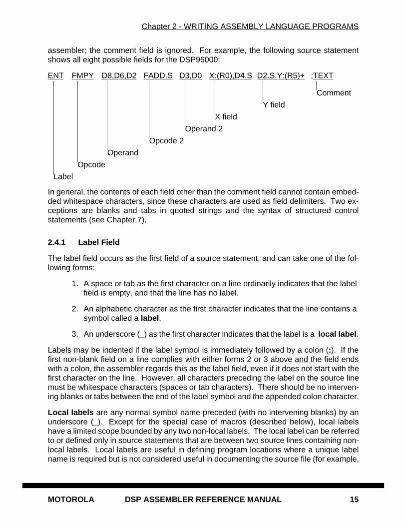
assembler; the comment field is ignored. For example, the following source statementshows all eight possible fields for the DSP96000:
ENT FMPY D8,D6,D2 FADD.S D3,D0 X:(R0),D4.S D2.S,Y:(R5)+ ;TEXT
In general, the contents of each field other than the comment field cannot contain embed-ded whitespace characters, since these characters are used as field delimiters. Two ex-ceptions are blanks and tabs in quoted strings and the syntax of structured controlstatements (see Chapter 7).
2.4.1 Label Field
The label field occurs as the first field of a source statement, and can take one of the fol-lowing forms:
1. A space or tab as the first character on a line ordinarily indicates that the label field is empty, and that the line has no label.
2. An alphabetic character as the first character indicates that the line contains a symbol called a label .
3. An underscore (_) as the first character indicates that the label is a local label .
Labels may be indented if the label symbol is immediately followed by a colon (:). If thefirst non-blank field on a line complies with either forms 2 or 3 above and the field endswith a colon, the assembler regards this as the label field, even if it does not start with thefirst character on the line. However, all characters preceding the label on the source linemust be whitespace characters (spaces or tab characters). There should be no interven-ing blanks or tabs between the end of the label symbol and the appended colon character.
Local labels are any normal symbol name preceded (with no intervening blanks) by anunderscore (_). Except for the special case of macros (described below), local labelshave a limited scope bounded by any two non-local labels. The local label can be referredto or defined only in source statements that are between two source lines containing non-local labels. Local labels are useful in defining program locations where a unique labelname is required but is not considered useful in documenting the source file (for example,
Label
Opcode
Operand
Opcode 2
Operand 2
X field
Y field
Comment
Chapter 2 - WRITING ASSEMBLY LANGUAGE PROGRAMS
16 DSP ASSEMBLER REFERENCE MANUAL MOTOROLA
the terminating address of a DO loop). Note that the maximum length of a local label in-cludes the leading underscore (_) character.
Use of local labels in macros represents a special case. All local labels within a macroare considered distinct for the currently active level of macro expansion (unless the macrolocal label override operator is used; see Chapter 5). These local labels are valid for theentire macro expansion and are not considered bounded by non-local labels. Therefore,all local labels within a macro must be unique. This mechanism allows the programmerto freely use local labels within a macro definition without regard to the number of timesthat the macro is expanded. Non-local labels within a macro expansion are consideredto be normal labels and therefore cannot occur more than once unless used with the SETdirective (see Chapter 6).
A label may occur only once in the label field of an individual source file unless it is usedas a local label, a label local to a section, or is used with the SET directive. If a non-locallabel does occur more than once in a label field, each reference to that label after the firstwill be flagged as an error.
A line consisting of a label only is a valid line and has the effect of assigning the value ofthe location counter to the label. With the exception of some directives, a label is assignedthe value of the location counter of the first word of the instruction or data being assem-bled.
2.4.2 Operation Field
The operation field appears after the label field, and must be preceded by at least onespace or tab. Entries in the operation field may be one of three types:
Opcode - Mnemonics that correspond directly to DSP machine instructions.
Directive - Special operation codes known to the assembler which control the assembly process.
Macro call - Invocation of a previously defined macro which is to be inserted in place of the macro call.
The assembler first searches for operation codes in an internal macro definition table. Ifno match is found, the table of machine operation codes and assembler directives issearched. If neither of the tables holds the specified operation code, an error message isgenerated (this sequence can be altered with the MACLIB directive). Macro names cantherefore replace standard machine operation codes and assembler directives, althougha warning will be issued if such a replacement occurs. The warning can be avoided byuse of the RDIRECT directive. See Chapter 6 for more information on the MACLIB andRDIRECT directives.
Chapter 2 - WRITING ASSEMBLY LANGUAGE PROGRAMS
MOTOROLA DSP ASSEMBLER REFERENCE MANUAL 17
2.4.3 Operand Field
The interpretation of the operand field is dependent on the contents of the operation field.The operand field, if present, must follow the operation field, and must be preceded by atleast one space or tab. The operand field may contain a symbol, an expression, or a com-bination of symbols and expressions separated by commas. There should be no inter-vening whitespace characters separating operand elements.
The operand field of machine instructions is used to specify the addressing mode of theinstruction, as well as the operand of the instruction. The format of the operand field fora particular instruction is given in Appendix A of the User Manual for the DSP in question(.e.g. DSP56000/DSP56001 User’s Manual ). The operand fields of assembler directivesare described in Chapter 6. The operand fields of macros (Chapter 5) depend on the def-inition of the macro.
2.4.4 Operation 2 Field
DSP96000 only. The second operation field occurs after the first operand field, and onlyin conjunction with an FMPY instruction. The field must be preceded by at least onespace or tab. The second operation field may consist only of the instructions FADD,FSUB, and FADDSUB .
2.4.5 Operand 2 Field
DSP96000 only. The interpretation of the second operand field is dependent on the con-tents of the second operation field. The second operand field, if present, must follow thesecond operation field, and must be preceded by at least one space or tab. The operandfield may contain only those register combinations appropriate to the second operationfield.
The operand field of machine instructions is used to specify the addressing mode of theinstruction, as well as the operand of the instruction. The format of the operand field foreach DSP96000 instruction is described in Appendix A of the DSP96002 User’s Manual .
2.4.6 Data Transfer Fields
Most opcodes can specify one or more data transfers to occur during the execution of theinstruction. These data transfers are indicated by two addressing mode operands sepa-rated by a comma, with no embedded blanks. If two data transfers are specified, theymust be separated by one or more blanks or tabs. See the appropriate DSP User’s Man-ual for a complete discussion of addressing modes that are applicable to data transferspecifications.
Chapter 2 - WRITING ASSEMBLY LANGUAGE PROGRAMS
18 DSP ASSEMBLER REFERENCE MANUAL MOTOROLA
2.4.7 Comment Field
Comments are not considered significant to the assembler, but can be included in thesource file for documentation purposes. A comment field is composed of any characters(not part of a literal string) that are preceded by a semicolon (;). A comment starting in thefirst column of the source file will be aligned with the label field in the listing file. Otherwise,the comment will be shifted right and aligned with the comment field in the listing file, un-less the NOPP option is used (see the OPT directive, Chapter 6). Comments precededby two consecutive semicolons (;; ) will not be reproduced on the assembler listing and willnot be saved as part of a macro definition.
2.5 ASSEMBLER OUTPUT
The assembler output consists of an optional listing of the source program and an optionalobject file. Appendix D contains the description of the source listing format and AppendixE contains the description of the object file format.
The assembly source program listing contains the original source statements, formattedfor easier reading, as well as additional information which is generated by the assembler.Most lines in the listing correspond directly to a source statement. Lines which do not cor-respond directly to source statements include page headings, error messages, and ex-pansions of macro calls or directives such as DC (Define Constant; see Chapter 6).
The assembly listing optionally may contain a symbol table or a cross-reference table ofall non-local symbols appearing in the program. These are always printed after the endof source input or the END directive (whichever occurs first) if either the symbol table orcross-reference table options are in effect (see the OPT directive, Chapter 6). The symboltable contains the name of each symbol, along with its defined value. The cross-referencetable additionally contains the assembler-maintained source line number of every refer-ence to every non-local symbol (local symbols may be included in the cross-reference list-ing by using the LOC option; see the OPT directive, Chapter 6). The format of the cross-reference table is shown in Appendix D.
If the MU option is enabled (see the OPT directive, Chapter 6), the assembler generatesa report of load and runtime memory utilization. The report shows beginning and endingaddresses of allocated memory areas, along with their lengths and associated symbolnames, if applicable. A separate report is generated for each memory space where datahas been reserved for use by the program. The format of the report is given in AppendixD.
The assembler object file is a binary COFF (Common Object File Format) file, with exten-sions and adaptations to support symbolic debugging and to make DSP object files trans-portable among host platforms. COFF is a formal definition for the structure of machinecode files. It is derived from AT&T Unix System V and represents a quasi-de facto stan-dard for object file formats. Refer to Appendix E for more information on Motorola DSPCOFF structure and layout.

MOTOROLA DSP ASSEMBLER REFERENCE MANUAL 19
Chapter 3 EXPRESSIONS
3.1 INTRODUCTION
An expression represents a value which is used as an operand in an assembler instructionor directive. An expression is a combination of symbols, constants, operators, and paren-theses. Expressions may contain user-defined labels and their associated integer orfloating point values, and/or any combination of integers, floating point numbers, or ASCIIliteral strings. In general, white space (a blank or tab) is not allowed between the termsand operators of an assembler expression. Expressions otherwise follow the convention-al rules of algebra and boolean arithmetic.
3.2 ABSOLUTE AND RELATIVE EXPRESSIONS
An expression may be either relative or absolute . An absolute expression is one whichconsists only of absolute terms, or is the result of two relative terms with opposing signs.A relative expression consists of a relative term by itself or only in combination with abso-lute terms.
When the assembler is operating in relative mode all address expressions must adhereto the above definitions for absolute or relative expressions. This is because only thesetypes of expressions will retain a meaningful value after program relocation. For example,when relative terms are paired with opposing signs, the result is the difference betweenthe two relative terms, which is an absolute value. However, if two positive relative termsare added together the result is unpredictable based on the computed values of the termsat relocation time.
3.3 EXPRESSION MEMORY SPACE ATTRIBUTE
A symbol is associated with either an integer or a floating point value which is used inplace of the symbol during the expression evaluation. Each symbol also carries a memoryspace attribute of either X, Y, L, Program, EMI, or None. SET labels, constants, and float-ing point expressions always have a memory space attribute of None. The result of anexpression will always have a memory space attribute associated with it. The unary log-ical negate operator, relational operators, and some functions return values that have amemory space attribute of N. The result of an expression that has only one operand (andpossibly the unary negate or unary minus operator) always has the memory attribute of
Chapter 3 - EXPRESSIONS
20 DSP ASSEMBLER REFERENCE MANUAL MOTOROLA
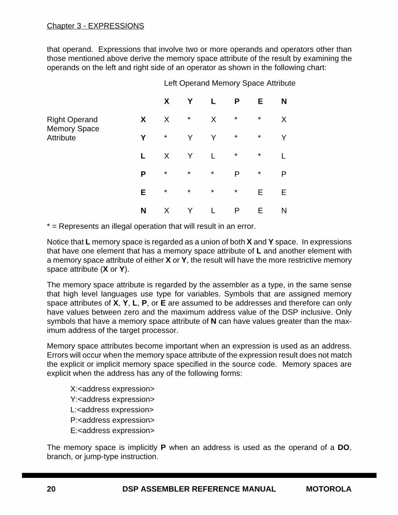
that operand. Expressions that involve two or more operands and operators other thanthose mentioned above derive the memory space attribute of the result by examining theoperands on the left and right side of an operator as shown in the following chart:
Left Operand Memory Space Attribute
X Y L P E N
Right Operand X X * X * * XMemory SpaceAttribute Y * Y Y * * Y
L X Y L * * L
P * * * P * P
E * * * * E E
N X Y L P E N
* = Represents an illegal operation that will result in an error.
Notice that L memory space is regarded as a union of both X and Y space. In expressionsthat have one element that has a memory space attribute of L and another element witha memory space attribute of either X or Y, the result will have the more restrictive memoryspace attribute (X or Y).
The memory space attribute is regarded by the assembler as a type, in the same sensethat high level languages use type for variables. Symbols that are assigned memoryspace attributes of X, Y, L, P, or E are assumed to be addresses and therefore can onlyhave values between zero and the maximum address value of the DSP inclusive. Onlysymbols that have a memory space attribute of N can have values greater than the max-imum address of the target processor.
Memory space attributes become important when an expression is used as an address.Errors will occur when the memory space attribute of the expression result does not matchthe explicit or implicit memory space specified in the source code. Memory spaces areexplicit when the address has any of the following forms:
X:<address expression> Y:<address expression>L:<address expression>P:<address expression>E:<address expression>
The memory space is implicitly P when an address is used as the operand of a DO,branch, or jump-type instruction.
Chapter 3 - EXPRESSIONS
MOTOROLA DSP ASSEMBLER REFERENCE MANUAL 21
Expressions used for immediate addressing can have any memory space attribute.
3.4 INTERNAL EXPRESSION REPRESENTATION
Expression value representation internal to the assembler is dependent on the word sizeof the target processor. The assembler supports a word and a double word integer formatinternally. The actual storage size of an expression value is dependent upon the magni-tude of the result, but the assembler is capable of representing signed integers up to 64bits in length. These longer integer representations are useful when performing data ini-tialization in L memory space.
Internal floating point representation is almost entirely dependent upon the host environ-ment, but in general floating point values are stored in double precision format. Thismeans that there are ordinarily 64 bits of storage allotted for a floating point number bythe assembler, with 11 bits of exponent, 53 bits of mantissa, and an implied binary point.
3.5 CONSTANTS
Constants represent quantities of data that do not vary in value during the execution of aprogram.
3.5.1 Numeric Constants
Numeric constants can be in one of three bases:
Binary Binary constants consist of a percent sign (%) followed by a string of binary digits (0,1).
Example: %11010
Hexadecimal Hexadecimal constants consist of a dollar sign ($) followed by a string of hexadecimal digits (0-9, A-F, a-f).
Example: $12FF, $12ff
Decimal Decimal constants can be either floating point or integer. Integer decimal constants consist of a string of decimal (0-9) digits op-tionally preceded by a grave accent (`). Floating point constants are indicated either by a preceding, following, or included decimal point or by the presence of an upper or lower case ‘E’ followed by the exponent.
Example:
12345 (integer)6E10 (floating point)
Chapter 3 - EXPRESSIONS
22 DSP ASSEMBLER REFERENCE MANUAL MOTOROLA
.6 (floating point)2.7e2 (floating point)
A constant may be written without a leading radix indicator if the input radix is changedusing the RADIX directive. For example, a hexadecimal constant may be written withoutthe leading dollar sign ($) if the input radix is set to16 (assuming an initial radix of 10). Thedefault radix is10. See Chapter 6 on the RADIX directive for more information.
3.5.2 String Constants
String constants that are used in expressions are converted to a concatenated sequenceof ASCII bytes (right aligned), as shown below. Strings used in expressions are limited tothe long word size of the target processor; subsequent characters in the string are ig-nored. Null strings (strings that have no characters) have a value of 0.
String constants greater than the maximum number of characters can be used in expres-sions, but the assembler will truncate the value and will use only those characters that willfit in a DSP long word. In this case, a warning will be printed. This restriction also appliesto string constants using the string concatenation operator. Handling of string constantsby the DC and DCB directives is an exception to this rule; see Chapter 6 for a description.
Examples:
'ABCD' ($41424344)'''79' ($00273739)'A' ($00000041)'' ($00000000) - null string'abcdef' ($61626364)'abc'++'de' ($61626364)
3.6 OPERATORS
Some of the assembler operators can be used with both floating point and integer values.If one of the operands of the operator has a floating point value and the other has an in-teger value, the integer will be converted to a floating point value before the operator isapplied and the result will be floating point. If both operands of the operator are integers,the result will be an integer value. Similarly, if both the operands are floating point, theresult will be a floating point value.
3.6.1 Unary operators
plus (+)minus (-)one’s complement (~) - Integer onlylogical negate (!)
Chapter 3 - EXPRESSIONS
MOTOROLA DSP ASSEMBLER REFERENCE MANUAL 23
The unary plus operator returns the value of its operand.
The unary minus operator returns the negative of its operand.
The one’s complement operator returns the one’s complement of its operand. It cannotbe used with a floating point operand.
The unary logical negation operator returns an integer 1 (memory space attribute None)if the value of its operand is 0 and will return a 0 otherwise. For example, if the symbolBUF had a value of 0, then !BUF would have a value of 1. If BUF had a value of 1000,!BUF would have a value of 0.
3.6.2 Arithmetic operators
addition (+)subtraction (-)multiplication (*)division (/)mod (%)
The addition operator yields the sum of its operands.
The subtraction operator yields the difference of its operands.
The multiplication operator yields the product of its operands.
The divide operator yields the quotient of the division of the first operand by the second.For integer operands the divide operation will produce a truncated integer result.
The mod operator applied to integers will yield the remainder from the division of the firstoperand by the second. If the mod operator is used with floating point operands, the modoperator will apply the following rules:
Y % Z = Y if Z = 0= X if Z <> 0
where X has the same sign as Y, is less than Z, and satisfies the relationship:
Y = i * Z + X
where i is an integer.
3.6.3 Shift operators
shift left (<<) - Integer onlyshift right (>>) - Integer only
Chapter 3 - EXPRESSIONS
24 DSP ASSEMBLER REFERENCE MANUAL MOTOROLA
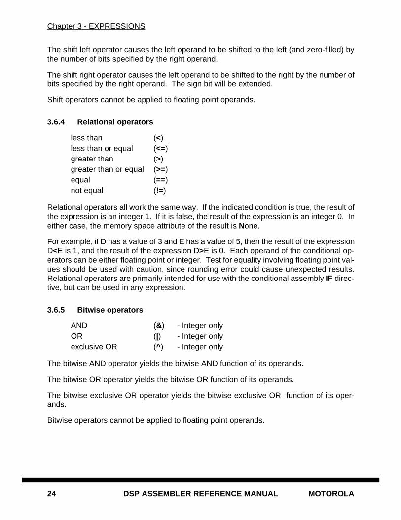
The shift left operator causes the left operand to be shifted to the left (and zero-filled) bythe number of bits specified by the right operand.
The shift right operator causes the left operand to be shifted to the right by the number ofbits specified by the right operand. The sign bit will be extended.
Shift operators cannot be applied to floating point operands.
3.6.4 Relational operators
less than (<)less than or equal (<=)greater than (>)greater than or equal (>=)equal (==)not equal (!=)
Relational operators all work the same way. If the indicated condition is true, the result ofthe expression is an integer 1. If it is false, the result of the expression is an integer 0. Ineither case, the memory space attribute of the result is None.
For example, if D has a value of 3 and E has a value of 5, then the result of the expressionD<E is 1, and the result of the expression D>E is 0. Each operand of the conditional op-erators can be either floating point or integer. Test for equality involving floating point val-ues should be used with caution, since rounding error could cause unexpected results.Relational operators are primarily intended for use with the conditional assembly IF direc-tive, but can be used in any expression.
3.6.5 Bitwise operators
AND (&) - Integer onlyOR (|) - Integer onlyexclusive OR (^ ) - Integer only
The bitwise AND operator yields the bitwise AND function of its operands.
The bitwise OR operator yields the bitwise OR function of its operands.
The bitwise exclusive OR operator yields the bitwise exclusive OR function of its oper-ands.
Bitwise operators cannot be applied to floating point operands.
Chapter 3 - EXPRESSIONS
MOTOROLA DSP ASSEMBLER REFERENCE MANUAL 25
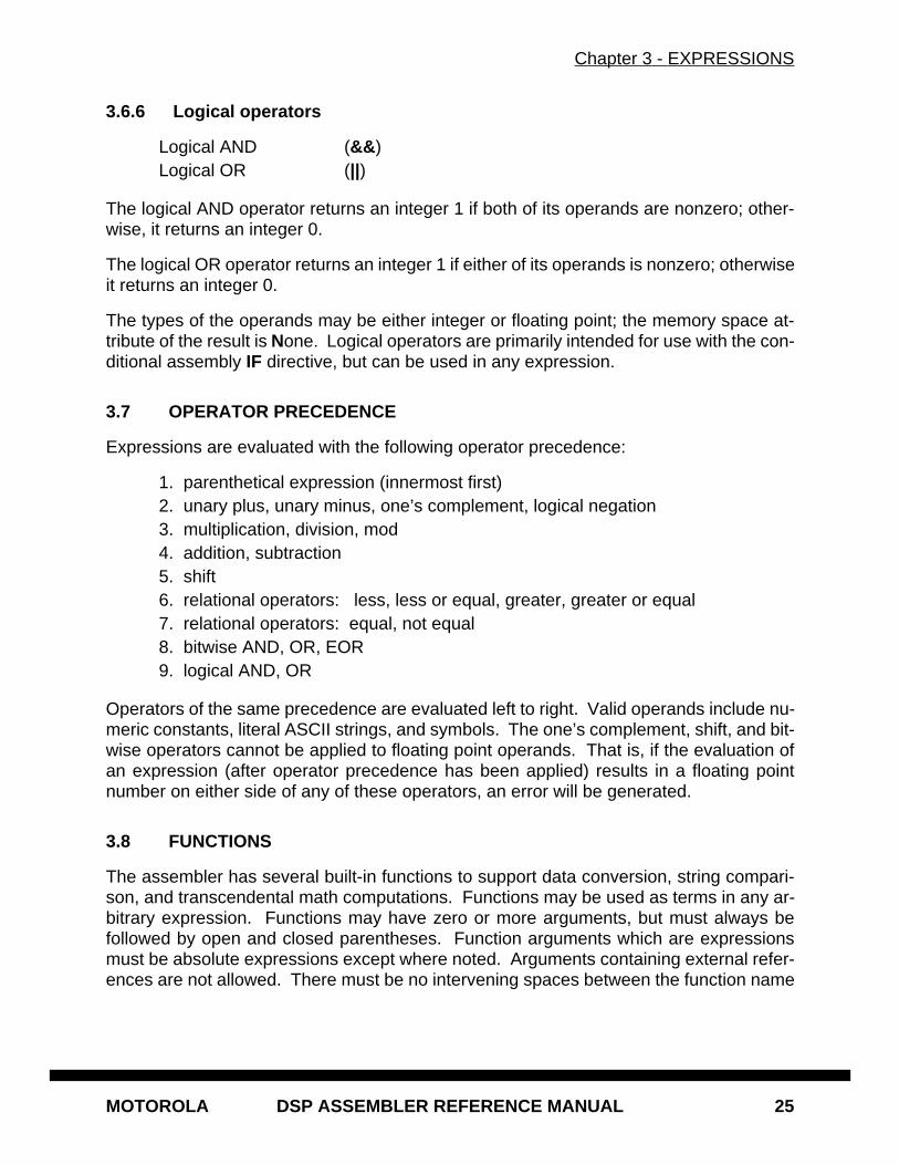
3.6.6 Logical operators
Logical AND (&& )Logical OR (||)
The logical AND operator returns an integer 1 if both of its operands are nonzero; other-wise, it returns an integer 0.
The logical OR operator returns an integer 1 if either of its operands is nonzero; otherwiseit returns an integer 0.
The types of the operands may be either integer or floating point; the memory space at-tribute of the result is None. Logical operators are primarily intended for use with the con-ditional assembly IF directive, but can be used in any expression.
3.7 OPERATOR PRECEDENCE
Expressions are evaluated with the following operator precedence:
1. parenthetical expression (innermost first)2. unary plus, unary minus, one’s complement, logical negation3. multiplication, division, mod4. addition, subtraction5. shift6. relational operators: less, less or equal, greater, greater or equal7. relational operators: equal, not equal8. bitwise AND, OR, EOR9. logical AND, OR
Operators of the same precedence are evaluated left to right. Valid operands include nu-meric constants, literal ASCII strings, and symbols. The one’s complement, shift, and bit-wise operators cannot be applied to floating point operands. That is, if the evaluation ofan expression (after operator precedence has been applied) results in a floating pointnumber on either side of any of these operators, an error will be generated.
3.8 FUNCTIONS
The assembler has several built-in functions to support data conversion, string compari-son, and transcendental math computations. Functions may be used as terms in any ar-bitrary expression. Functions may have zero or more arguments, but must always befollowed by open and closed parentheses. Function arguments which are expressionsmust be absolute expressions except where noted. Arguments containing external refer-ences are not allowed. There must be no intervening spaces between the function name
Chapter 3 - EXPRESSIONS
26 DSP ASSEMBLER REFERENCE MANUAL MOTOROLA
and the opening parenthesis, and there must be no spaces between comma-separatedarguments.
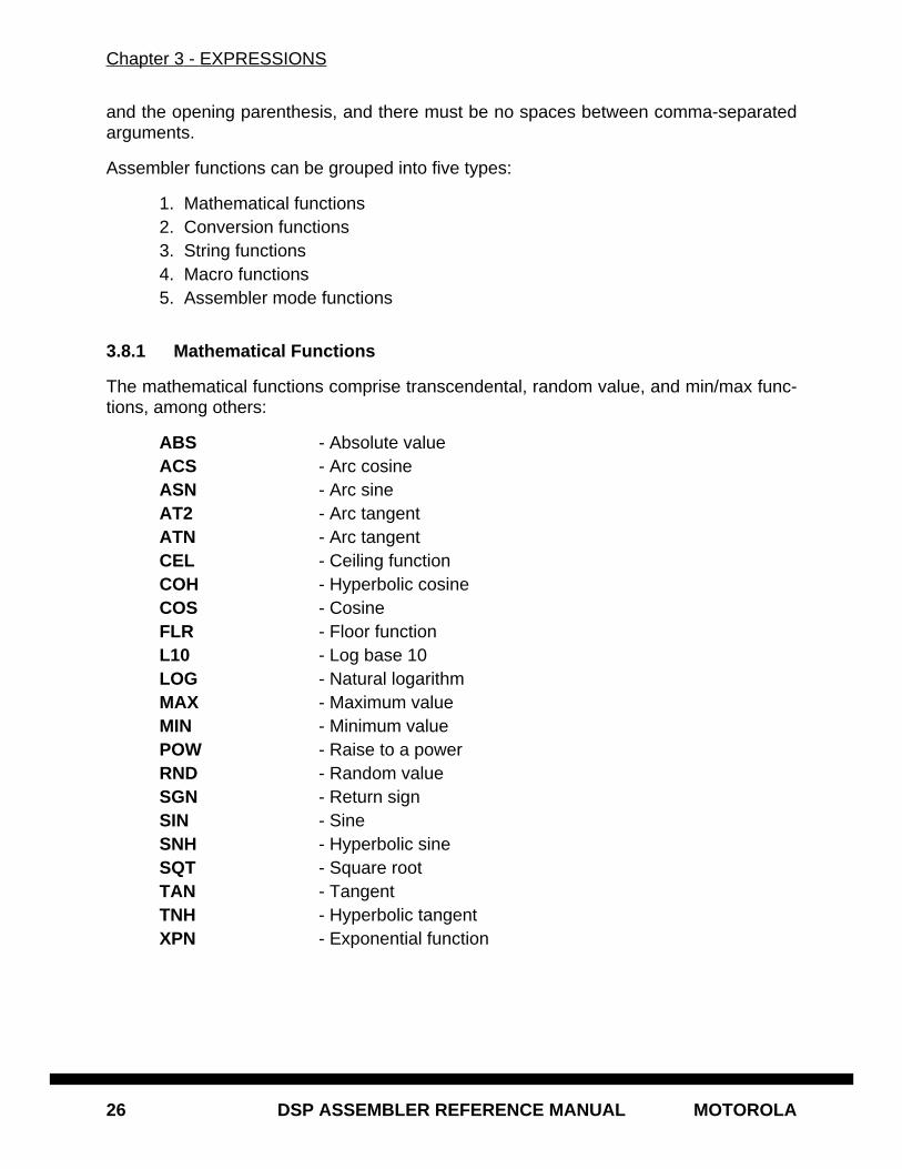
Assembler functions can be grouped into five types:
1. Mathematical functions2. Conversion functions3. String functions4. Macro functions5. Assembler mode functions
3.8.1 Mathematical Functions
The mathematical functions comprise transcendental, random value, and min/max func-tions, among others:
ABS - Absolute valueACS - Arc cosineASN - Arc sineAT2 - Arc tangentATN - Arc tangentCEL - Ceiling functionCOH - Hyperbolic cosineCOS - CosineFLR - Floor functionL10 - Log base 10LOG - Natural logarithmMAX - Maximum valueMIN - Minimum valuePOW - Raise to a powerRND - Random valueSGN - Return signSIN - SineSNH - Hyperbolic sineSQT - Square rootTAN - TangentTNH - Hyperbolic tangentXPN - Exponential function
Chapter 3 - EXPRESSIONS
MOTOROLA DSP ASSEMBLER REFERENCE MANUAL 27
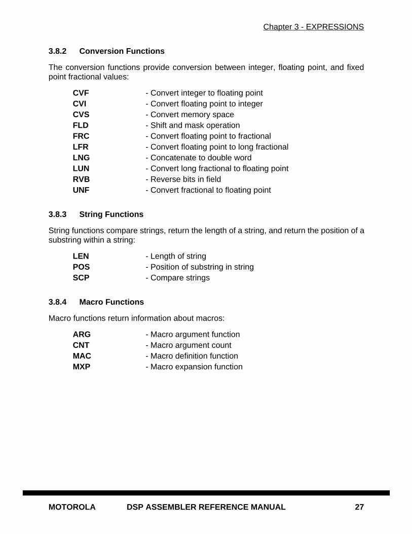
3.8.2 Conversion Functions
The conversion functions provide conversion between integer, floating point, and fixedpoint fractional values:
CVF - Convert integer to floating pointCVI - Convert floating point to integerCVS - Convert memory spaceFLD - Shift and mask operationFRC - Convert floating point to fractionalLFR - Convert floating point to long fractionalLNG - Concatenate to double wordLUN - Convert long fractional to floating pointRVB - Reverse bits in fieldUNF - Convert fractional to floating point
3.8.3 String Functions
String functions compare strings, return the length of a string, and return the position of asubstring within a string:
LEN - Length of stringPOS - Position of substring in stringSCP - Compare strings
3.8.4 Macro Functions
Macro functions return information about macros:
ARG - Macro argument functionCNT - Macro argument countMAC - Macro definition functionMXP - Macro expansion function
Chapter 3 - EXPRESSIONS
28 DSP ASSEMBLER REFERENCE MANUAL MOTOROLA
3.8.5 Assembler Mode Functions
Miscellaneous functions having to do with assembler operation:
CCC - Cumulative cycle countCHK - Current instruction/data checksumCTR - Location counter typeDEF - Symbol definition functionEXP - Expression checkINT - Integer checkLCV - Location counter valueLST - LIST directive flag valueMSP - Memory spaceREL - Relative mode function
Individual descriptions of each of the assembler functions follow. They include usageguidelines, functional descriptions, and examples.
@ABS(<expression>)
Returns the absolute value of <expression> as a floating point value. The memoryspace attribute of the result will be None.
Example:
MOVE #@ABS(VAL),D4.S ; load absolute value
@ACS(<expression>)
Returns the arc cosine of <expression> as a floating point value in the range zeroto pi. The result of <expression> must be between -1 and 1. The memory spaceattribute of the result will be None.
Example:
ACOS = @ACS(-1.0) ; ACOS = 3.141593
@ARG(<symbol> | <expression>)
Returns integer 1 if the macro argument represented by <symbol> or <expression>is present, 0 otherwise. If the argument is a symbol it must be single-quoted andrefer to a dummy argument name. If the argument is an expression it refers to theordinal position of the argument in the macro dummy argument list. A warning willbe issued if this function is used when no macro expansion is active. The memoryspace attribute of the result will be None.
Example:
IF @ARG(TWIDDLE) ; twiddle factor provided?
Chapter 3 - EXPRESSIONS
MOTOROLA DSP ASSEMBLER REFERENCE MANUAL 29
@ASN(<expression>)
Returns the arc sine of <expression> as a floating point value in the range -pi/2 topi/2. The result of <expression> must be between -1 and 1. The memory spaceattribute of the result will be None.
Example:
ARCSINE SET @ASN(-1.0) ; ARCSINE = -1.570796
@AT2(<expr1,expr2>)
Returns the arc tangent of <expr1>/<expr2> as a floating point value in the range-pi to pi. Expr1 and expr2 must be separated by a comma. The memory spaceattribute of the result will be None.
Example:
ATAN EQU @AT2(-1.0,1.0) ; ATAN = -0.7853982
@ATN(<expression>)
Returns the arc tangent of <expression> as a floating point value in the range -pi/2 to pi/2. The memory space attribute of the result will be None.
Example:
MOVE #@ATN(1.0),D0.S ; load arc tangent
@CCC()
Returns the cumulative cycle count as an integer. Useful in conjunction with theCC, NOCC, and CONTCC assembler options (see the OPT directive). The mem-ory space attribute of the result will be None.
Example:
IF @CCC() > 200 ; cycle count > 200?
@CEL(<expression>)
Returns a floating point value which represents the smallest integer greater than orequal to <expression>. The memory space attribute of the result will be None.
Example:
CEIL SET @CEL(-1.05) ; CEIL = -1.0
Chapter 3 - EXPRESSIONS
30 DSP ASSEMBLER REFERENCE MANUAL MOTOROLA
@CHK()
Returns the current instruction/data checksum value as an integer. Useful in con-junction with the CK, NOCK, and CONTCK assembler options (see the OPT direc-tive). Note that assignment of the checksum value with directives other than SETcould cause phasing errors due to different generated instruction values betweenpasses. The memory space attribute of the result will be None.
Example:
CHKSUM SET @CHK() ; reserve checksum value
@CNT()
Returns the count of the current macro expansion arguments as an integer. Awarning will be issued if this function is used when no macro expansion is active.The memory space attribute of the result will be None.
Example:
ARGCNT SET @CNT() ; squirrel away arg count
@COH(<expression>)
Returns the hyperbolic cosine of <expression> as a floating point value. The mem-ory space attribute of the result will be None.
Example:
HYCOS EQU @COH(VAL) ; compute hyperbolic cosine
@COS(<expression>)
Returns the cosine of <expression> as a floating point value. The memory spaceattribute of the result will be None.
Example:
DC -@COS(@CVF(COUNT)*FREQ) ; compute cosine value
@CTR({L | R})
If L is specified as the argument, returns the counter number of the load locationcounter. If R is specified, returns the counter number of the runtime locationcounter. The counter number is returned as an integer value with memory spaceof None.
Example:
CNUM = @CTR(R) ; runtime counter number
Chapter 3 - EXPRESSIONS
MOTOROLA DSP ASSEMBLER REFERENCE MANUAL 31
@CVF(<expression>)
Converts the result of <expression> to a floating point value. The memory spaceattribute of the result will be None.
Example:
FLOAT SET @CVF(5) ; FLOAT = 5.0
@CVI(<expression>)
Converts the result of <expression> to an integer value. This function should beused with caution since the conversions can be inexact (e.g., floating point valuesare truncated). The memory space attribute of the result will be None.
Example:
INT SET @CVI(-1.05) ; INT = -1
@CVS({X | Y | L | P | E | N},<expression>)
Converts the memory space attribute of <expression> to that specified by the firstargument; returns <expression>. See section 3.3 for more information on memoryspace attributes. The <expression> may be relative or absolute.
Example:
LOADDR EQU @CVS(X,TARGET) ; set LOADDR to X:TARGET
@DEF(<symbol>)
Returns an integer 1 (memory space attribute N) if <symbol> has been defined, 0otherwise. <symbol> may be any label not associated with a MACRO or SECTIONdirective. If <symbol> is quoted it is looked up as a DEFINE symbol; if it is not quot-ed it is looked up as an ordinary label.
Example:
IF @DEF(ANGLE) ; assemble if ANGLE defined
@EXP(<expression>)
Returns an integer 1 (memory space attribute N) if the evaluation of <expression>would not result in errors. Returns 0 if the evaluation of <expression> would causean error. No error will be output by the assembler if <expression> contains an er-ror. No test is made by the assembler for warnings. The <expression> may berelative or absolute.
Example:
IF !@EXP(@FRC(VAL)) ; skip on error
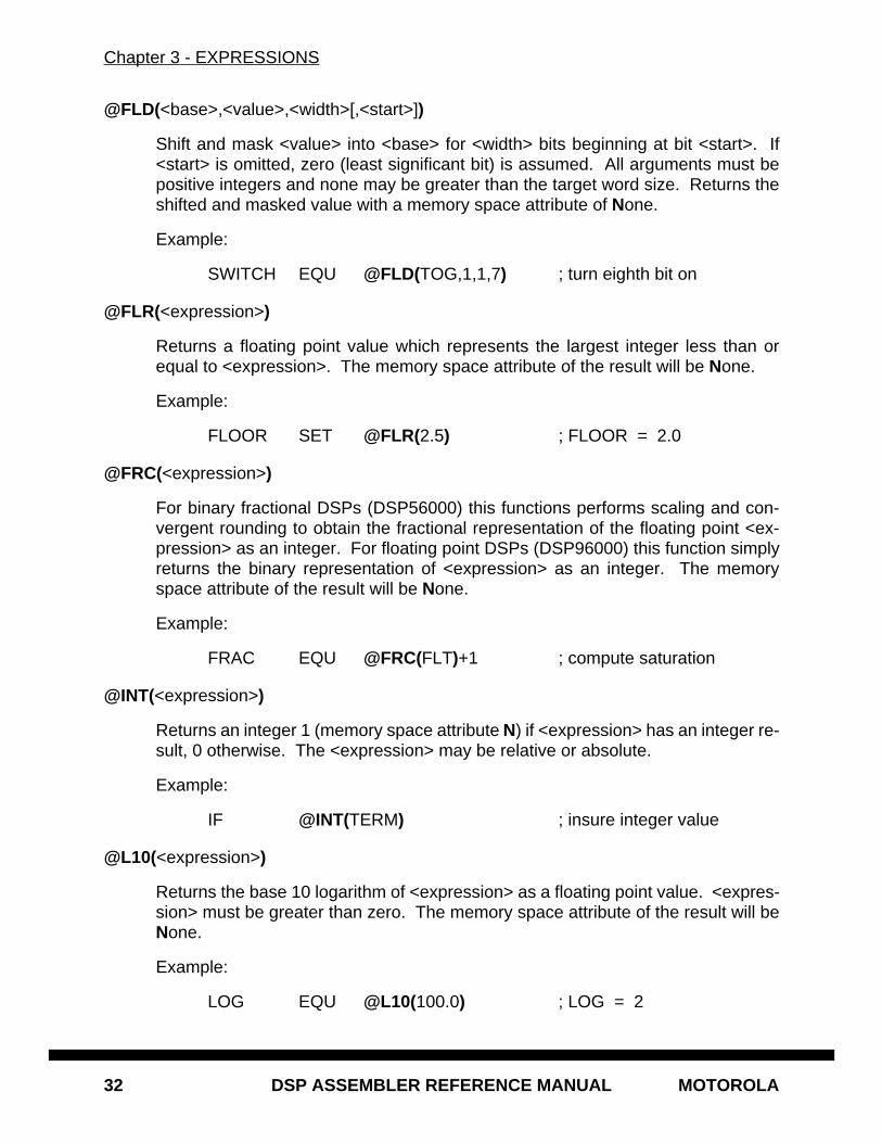
Chapter 3 - EXPRESSIONS
32 DSP ASSEMBLER REFERENCE MANUAL MOTOROLA
@FLD(<base>,<value>,<width>[,<start>])
Shift and mask <value> into <base> for <width> bits beginning at bit <start>. If<start> is omitted, zero (least significant bit) is assumed. All arguments must bepositive integers and none may be greater than the target word size. Returns theshifted and masked value with a memory space attribute of None.
Example:
SWITCH EQU @FLD(TOG,1,1,7) ; turn eighth bit on
@FLR(<expression>)
Returns a floating point value which represents the largest integer less than orequal to <expression>. The memory space attribute of the result will be None.
Example:
FLOOR SET @FLR(2.5) ; FLOOR = 2.0
@FRC(<expression>)
For binary fractional DSPs (DSP56000) this functions performs scaling and con-vergent rounding to obtain the fractional representation of the floating point <ex-pression> as an integer. For floating point DSPs (DSP96000) this function simplyreturns the binary representation of <expression> as an integer. The memoryspace attribute of the result will be None.
Example:
FRAC EQU @FRC(FLT)+1 ; compute saturation
@INT(<expression>)
Returns an integer 1 (memory space attribute N) if <expression> has an integer re-sult, 0 otherwise. The <expression> may be relative or absolute.
Example:
IF @INT(TERM) ; insure integer value
@L10(<expression>)
Returns the base 10 logarithm of <expression> as a floating point value. <expres-sion> must be greater than zero. The memory space attribute of the result will beNone.
Example:
LOG EQU @L10(100.0) ; LOG = 2
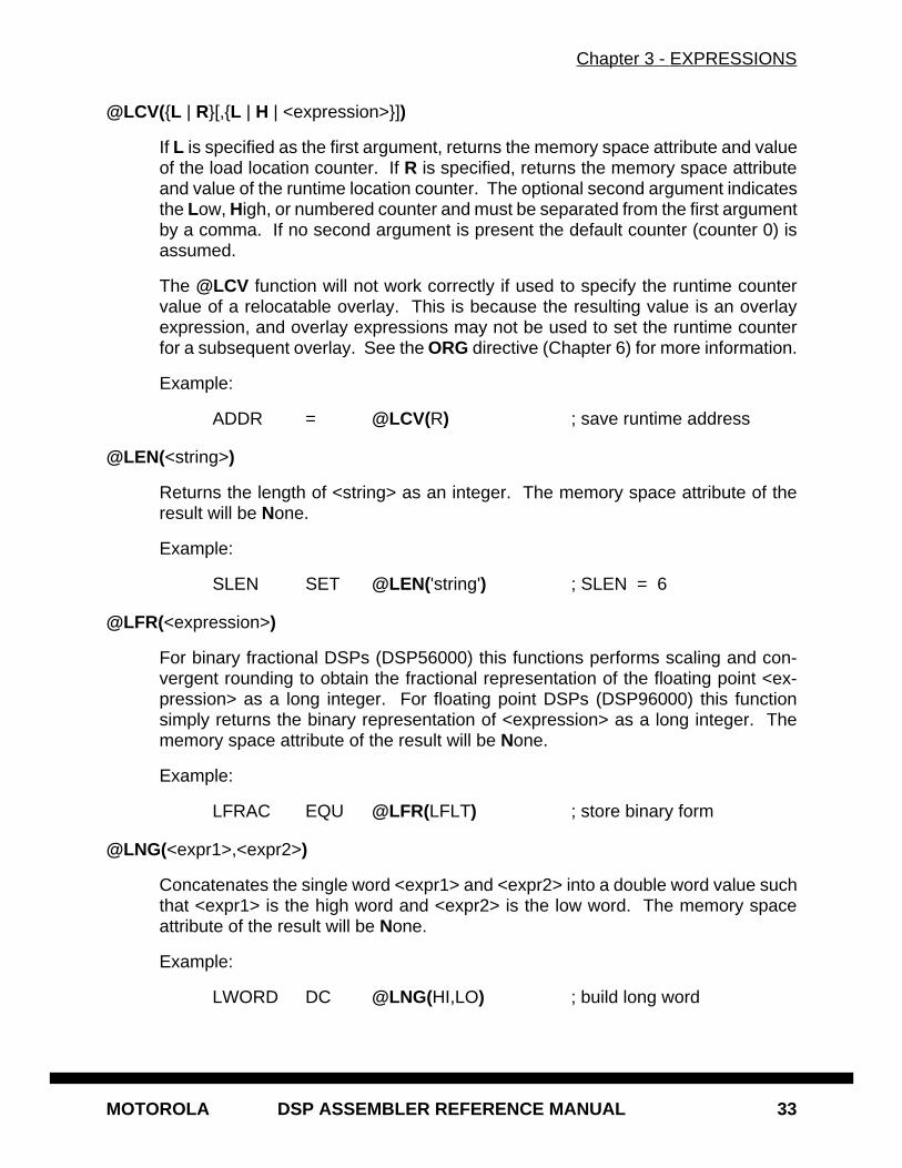
Chapter 3 - EXPRESSIONS
MOTOROLA DSP ASSEMBLER REFERENCE MANUAL 33
@LCV({L | R}[,{L | H | <expression>}])
If L is specified as the first argument, returns the memory space attribute and valueof the load location counter. If R is specified, returns the memory space attributeand value of the runtime location counter. The optional second argument indicatesthe Low, High, or numbered counter and must be separated from the first argumentby a comma. If no second argument is present the default counter (counter 0) isassumed.
The @LCV function will not work correctly if used to specify the runtime countervalue of a relocatable overlay. This is because the resulting value is an overlayexpression, and overlay expressions may not be used to set the runtime counterfor a subsequent overlay. See the ORG directive (Chapter 6) for more information.
Example:
ADDR = @LCV(R) ; save runtime address
@LEN(<string>)
Returns the length of <string> as an integer. The memory space attribute of theresult will be None.
Example:
SLEN SET @LEN('string') ; SLEN = 6
@LFR(<expression>)
For binary fractional DSPs (DSP56000) this functions performs scaling and con-vergent rounding to obtain the fractional representation of the floating point <ex-pression> as a long integer. For floating point DSPs (DSP96000) this functionsimply returns the binary representation of <expression> as a long integer. Thememory space attribute of the result will be None.
Example:
LFRAC EQU @LFR(LFLT) ; store binary form
@LNG(<expr1>,<expr2>)
Concatenates the single word <expr1> and <expr2> into a double word value suchthat <expr1> is the high word and <expr2> is the low word. The memory spaceattribute of the result will be None.
Example:
LWORD DC @LNG(HI,LO) ; build long word
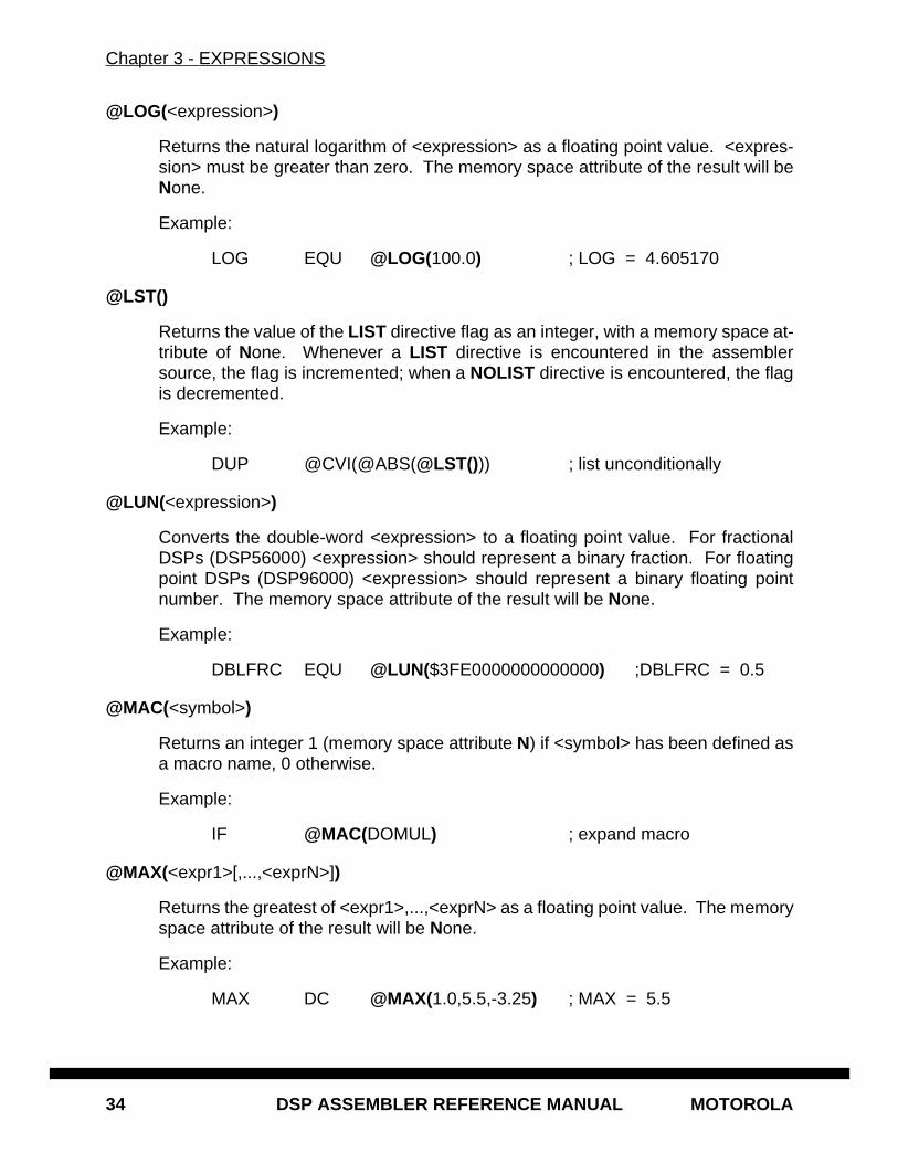
Chapter 3 - EXPRESSIONS
34 DSP ASSEMBLER REFERENCE MANUAL MOTOROLA
@LOG(<expression>)
Returns the natural logarithm of <expression> as a floating point value. <expres-sion> must be greater than zero. The memory space attribute of the result will beNone.
Example:
LOG EQU @LOG(100.0) ; LOG = 4.605170
@LST()
Returns the value of the LIST directive flag as an integer, with a memory space at-tribute of None. Whenever a LIST directive is encountered in the assemblersource, the flag is incremented; when a NOLIST directive is encountered, the flagis decremented.
Example:
DUP @CVI(@ABS(@LST())) ; list unconditionally
@LUN(<expression>)
Converts the double-word <expression> to a floating point value. For fractionalDSPs (DSP56000) <expression> should represent a binary fraction. For floatingpoint DSPs (DSP96000) <expression> should represent a binary floating pointnumber. The memory space attribute of the result will be None.
Example:
DBLFRC EQU @LUN($3FE0000000000000) ;DBLFRC = 0.5
@MAC(<symbol>)
Returns an integer 1 (memory space attribute N) if <symbol> has been defined asa macro name, 0 otherwise.
Example:
IF @MAC(DOMUL) ; expand macro
@MAX(<expr1>[,...,<exprN>])
Returns the greatest of <expr1>,...,<exprN> as a floating point value. The memoryspace attribute of the result will be None.
Example:
MAX DC @MAX(1.0,5.5,-3.25) ; MAX = 5.5
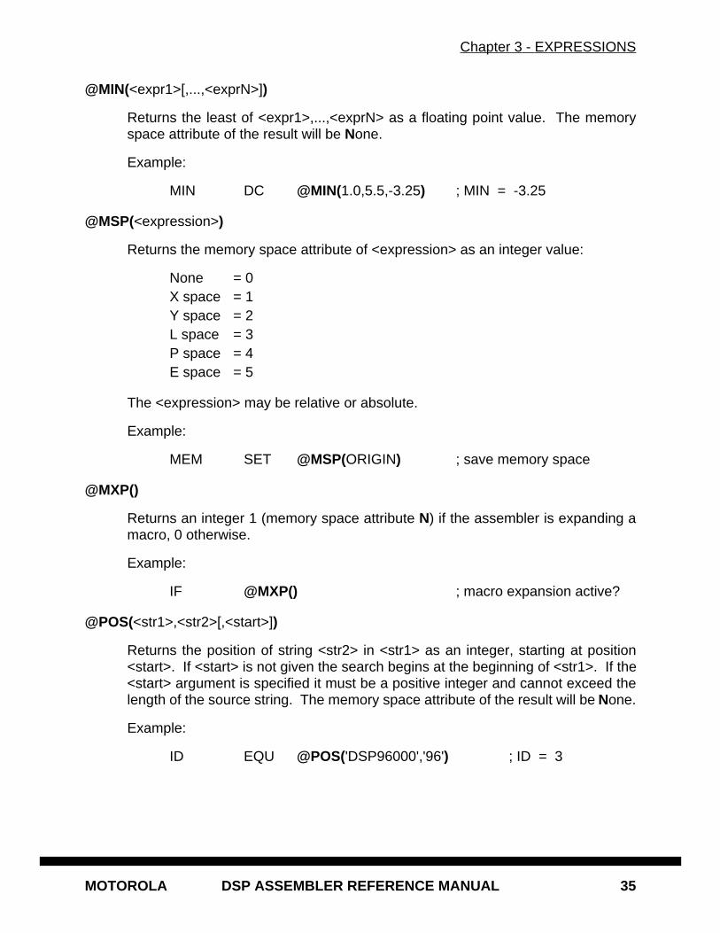
Chapter 3 - EXPRESSIONS
MOTOROLA DSP ASSEMBLER REFERENCE MANUAL 35
@MIN(<expr1>[,...,<exprN>])
Returns the least of <expr1>,...,<exprN> as a floating point value. The memoryspace attribute of the result will be None.
Example:
MIN DC @MIN(1.0,5.5,-3.25) ; MIN = -3.25
@MSP(<expression>)
Returns the memory space attribute of <expression> as an integer value:
None = 0X space = 1Y space = 2L space = 3P space = 4E space = 5
The <expression> may be relative or absolute.
Example:
MEM SET @MSP(ORIGIN) ; save memory space
@MXP()
Returns an integer 1 (memory space attribute N) if the assembler is expanding amacro, 0 otherwise.
Example:
IF @MXP() ; macro expansion active?
@POS(<str1>,<str2>[,<start>])
Returns the position of string <str2> in <str1> as an integer, starting at position<start>. If <start> is not given the search begins at the beginning of <str1>. If the<start> argument is specified it must be a positive integer and cannot exceed thelength of the source string. The memory space attribute of the result will be None.
Example:
ID EQU @POS('DSP96000','96') ; ID = 3
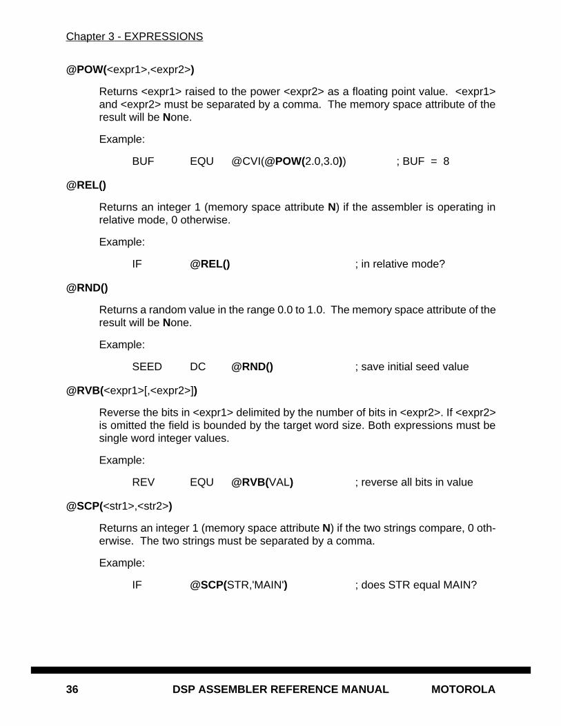
Chapter 3 - EXPRESSIONS
36 DSP ASSEMBLER REFERENCE MANUAL MOTOROLA
@POW(<expr1>,<expr2>)
Returns <expr1> raised to the power <expr2> as a floating point value. <expr1>and <expr2> must be separated by a comma. The memory space attribute of theresult will be None.
Example:
BUF EQU @CVI(@POW(2.0,3.0)) ; BUF = 8
@REL()
Returns an integer 1 (memory space attribute N) if the assembler is operating inrelative mode, 0 otherwise.
Example:
IF @REL() ; in relative mode?
@RND()
Returns a random value in the range 0.0 to 1.0. The memory space attribute of theresult will be None.
Example:
SEED DC @RND() ; save initial seed value
@RVB(<expr1>[,<expr2>])
Reverse the bits in <expr1> delimited by the number of bits in <expr2>. If <expr2>is omitted the field is bounded by the target word size. Both expressions must besingle word integer values.
Example:
REV EQU @RVB(VAL) ; reverse all bits in value
@SCP(<str1>,<str2>)
Returns an integer 1 (memory space attribute N) if the two strings compare, 0 oth-erwise. The two strings must be separated by a comma.
Example:
IF @SCP(STR,'MAIN') ; does STR equal MAIN?
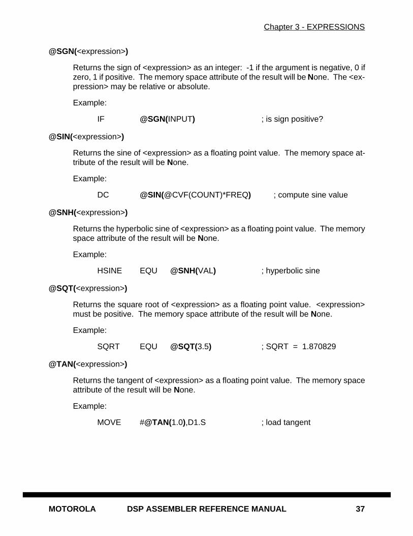
Chapter 3 - EXPRESSIONS
MOTOROLA DSP ASSEMBLER REFERENCE MANUAL 37
@SGN(<expression>)
Returns the sign of <expression> as an integer: -1 if the argument is negative, 0 ifzero, 1 if positive. The memory space attribute of the result will be None. The <ex-pression> may be relative or absolute.
Example:
IF @SGN(INPUT) ; is sign positive?
@SIN(<expression>)
Returns the sine of <expression> as a floating point value. The memory space at-tribute of the result will be None.
Example:
DC @SIN(@CVF(COUNT)*FREQ) ; compute sine value
@SNH(<expression>)
Returns the hyperbolic sine of <expression> as a floating point value. The memoryspace attribute of the result will be None.
Example:
HSINE EQU @SNH(VAL) ; hyperbolic sine
@SQT(<expression>)
Returns the square root of <expression> as a floating point value. <expression>must be positive. The memory space attribute of the result will be None.
Example:
SQRT EQU @SQT(3.5) ; SQRT = 1.870829
@TAN(<expression>)
Returns the tangent of <expression> as a floating point value. The memory spaceattribute of the result will be None.
Example:
MOVE #@TAN(1.0),D1.S ; load tangent
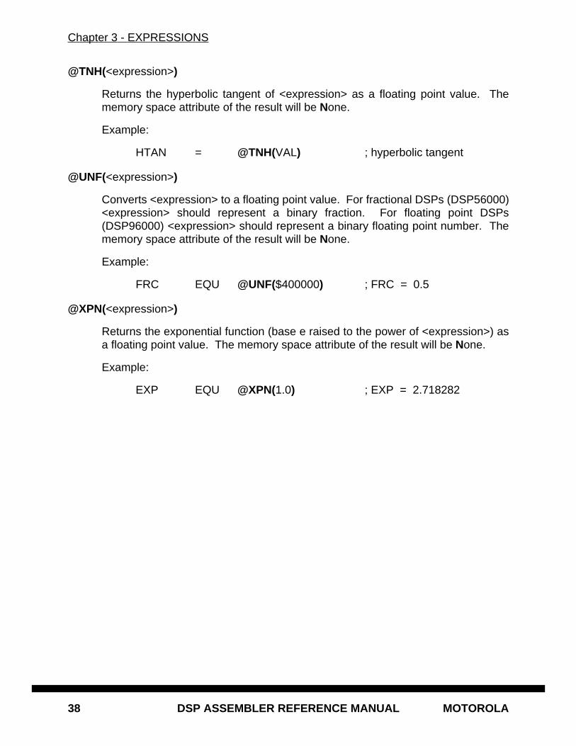
Chapter 3 - EXPRESSIONS
38 DSP ASSEMBLER REFERENCE MANUAL MOTOROLA
@TNH(<expression>)
Returns the hyperbolic tangent of <expression> as a floating point value. Thememory space attribute of the result will be None.
Example:
HTAN = @TNH(VAL) ; hyperbolic tangent
@UNF(<expression>)
Converts <expression> to a floating point value. For fractional DSPs (DSP56000)<expression> should represent a binary fraction. For floating point DSPs(DSP96000) <expression> should represent a binary floating point number. Thememory space attribute of the result will be None.
Example:
FRC EQU @UNF($400000) ; FRC = 0.5
@XPN(<expression>)
Returns the exponential function (base e raised to the power of <expression>) asa floating point value. The memory space attribute of the result will be None.
Example:
EXP EQU @XPN(1.0) ; EXP = 2.718282
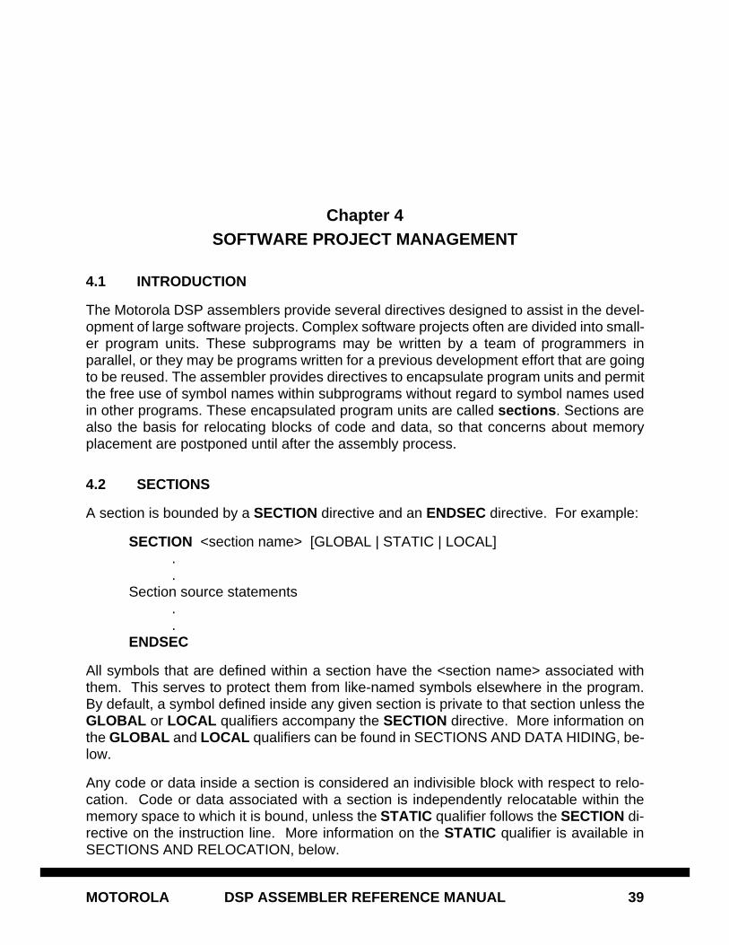
MOTOROLA DSP ASSEMBLER REFERENCE MANUAL 39
Chapter 4SOFTWARE PROJECT MANAGEMENT
4.1 INTRODUCTION
The Motorola DSP assemblers provide several directives designed to assist in the devel-opment of large software projects. Complex software projects often are divided into small-er program units. These subprograms may be written by a team of programmers inparallel, or they may be programs written for a previous development effort that are goingto be reused. The assembler provides directives to encapsulate program units and permitthe free use of symbol names within subprograms without regard to symbol names usedin other programs. These encapsulated program units are called sections . Sections arealso the basis for relocating blocks of code and data, so that concerns about memoryplacement are postponed until after the assembly process.
4.2 SECTIONS
A section is bounded by a SECTION directive and an ENDSEC directive. For example:
SECTION <section name> [GLOBAL | STATIC | LOCAL]..
Section source statements..
ENDSEC
All symbols that are defined within a section have the <section name> associated withthem. This serves to protect them from like-named symbols elsewhere in the program.By default, a symbol defined inside any given section is private to that section unless theGLOBAL or LOCAL qualifiers accompany the SECTION directive. More information onthe GLOBAL and LOCAL qualifiers can be found in SECTIONS AND DATA HIDING, be-low.
Any code or data inside a section is considered an indivisible block with respect to relo-cation. Code or data associated with a section is independently relocatable within thememory space to which it is bound, unless the STATIC qualifier follows the SECTION di-rective on the instruction line. More information on the STATIC qualifier is available inSECTIONS AND RELOCATION, below.
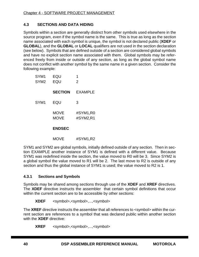
Chapter 4 - SOFTWARE PROJECT MANAGEMENT
40 DSP ASSEMBLER REFERENCE MANUAL MOTOROLA
4.3 SECTIONS AND DATA HIDING
Symbols within a section are generally distinct from other symbols used elsewhere in thesource program, even if the symbol name is the same. This is true as long as the sectionname associated with each symbol is unique, the symbol is not declared public (XDEF orGLOBAL ), and the GLOBAL or LOCAL qualifiers are not used in the section declaration(see below). Symbols that are defined outside of a section are considered global symbolsand have no explicit section name associated with them. Global symbols may be refer-enced freely from inside or outside of any section, as long as the global symbol namedoes not conflict with another symbol by the same name in a given section. Consider thefollowing example:
SYM1 EQU 1SYM2 EQU 2
SECTION EXAMPLE
SYM1 EQU 3
MOVE #SYM1,R0MOVE #SYM2,R1
ENDSEC
MOVE #SYM1,R2
SYM1 and SYM2 are global symbols, initially defined outside of any section. Then in sec-tion EXAMPLE another instance of SYM1 is defined with a different value. BecauseSYM1 was redefined inside the section, the value moved to R0 will be 3. Since SYM2 isa global symbol the value moved to R1 will be 2. The last move to R2 is outside of anysection and thus the global instance of SYM1 is used; the value moved to R2 is 1.
4.3.1 Sections and Symbols
Symbols may be shared among sections through use of the XDEF and XREF directives.The XDEF directive instructs the assembler that certain symbol definitions that occurwithin the current section are to be accessible by other sections:
XDEF <symbol>,<symbol>,...,<symbol>
The XREF directive instructs the assembler that all references to <symbol> within the cur-rent section are references to a symbol that was declared public within another sectionwith the XDEF directive:
XREF <symbol>,<symbol>,...,<symbol>
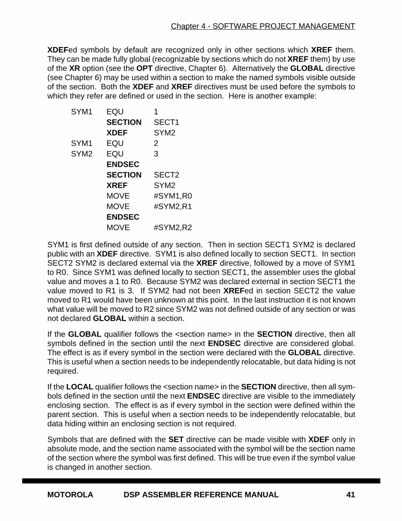
Chapter 4 - SOFTWARE PROJECT MANAGEMENT
MOTOROLA DSP ASSEMBLER REFERENCE MANUAL 41
XDEFed symbols by default are recognized only in other sections which XREF them.They can be made fully global (recognizable by sections which do not XREF them) by useof the XR option (see the OPT directive, Chapter 6). Alternatively the GLOBAL directive(see Chapter 6) may be used within a section to make the named symbols visible outsideof the section. Both the XDEF and XREF directives must be used before the symbols towhich they refer are defined or used in the section. Here is another example:
SYM1 EQU 1SECTION SECT1XDEF SYM2
SYM1 EQU 2SYM2 EQU 3
ENDSECSECTION SECT2XREF SYM2MOVE #SYM1,R0MOVE #SYM2,R1ENDSECMOVE #SYM2,R2
SYM1 is first defined outside of any section. Then in section SECT1 SYM2 is declaredpublic with an XDEF directive. SYM1 is also defined locally to section SECT1. In sectionSECT2 SYM2 is declared external via the XREF directive, followed by a move of SYM1to R0. Since SYM1 was defined locally to section SECT1, the assembler uses the globalvalue and moves a 1 to R0. Because SYM2 was declared external in section SECT1 thevalue moved to R1 is 3. If SYM2 had not been XREFed in section SECT2 the valuemoved to R1 would have been unknown at this point. In the last instruction it is not knownwhat value will be moved to R2 since SYM2 was not defined outside of any section or wasnot declared GLOBAL within a section.
If the GLOBAL qualifier follows the <section name> in the SECTION directive, then allsymbols defined in the section until the next ENDSEC directive are considered global.The effect is as if every symbol in the section were declared with the GLOBAL directive.This is useful when a section needs to be independently relocatable, but data hiding is notrequired.
If the LOCAL qualifier follows the <section name> in the SECTION directive, then all sym-bols defined in the section until the next ENDSEC directive are visible to the immediatelyenclosing section. The effect is as if every symbol in the section were defined within theparent section. This is useful when a section needs to be independently relocatable, butdata hiding within an enclosing section is not required.
Symbols that are defined with the SET directive can be made visible with XDEF only inabsolute mode, and the section name associated with the symbol will be the section nameof the section where the symbol was first defined. This will be true even if the symbol valueis changed in another section.
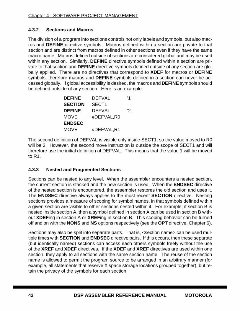
Chapter 4 - SOFTWARE PROJECT MANAGEMENT
42 DSP ASSEMBLER REFERENCE MANUAL MOTOROLA
4.3.2 Sections and Macros
The division of a program into sections controls not only labels and symbols, but also mac-ros and DEFINE directive symbols. Macros defined within a section are private to thatsection and are distinct from macros defined in other sections even if they have the samemacro name. Macros defined outside of sections are considered global and may be usedwithin any section. Similarly, DEFINE directive symbols defined within a section are pri-vate to that section and DEFINE directive symbols defined outside of any section are glo-bally applied. There are no directives that correspond to XDEF for macros or DEFINEsymbols, therefore macros and DEFINE symbols defined in a section can never be ac-cessed globally. If global accessibility is desired, the macros and DEFINE symbols shouldbe defined outside of any section. Here is an example:
DEFINE DEFVAL '1'SECTION SECT1DEFINE DEFVAL '2'MOVE #DEFVAL,R0ENDSECMOVE #DEFVAL,R1
The second definition of DEFVAL is visible only inside SECT1, so the value moved to R0will be 2. However, the second move instruction is outside the scope of SECT1 and willtherefore use the initial definition of DEFVAL. This means that the value 1 will be movedto R1.
4.3.3 Nested and Fragmented Sections
Sections can be nested to any level. When the assembler encounters a nested section,the current section is stacked and the new section is used. When the ENDSEC directiveof the nested section is encountered, the assembler restores the old section and uses it.The ENDSEC directive always applies to the most recent SECTION directive. Nestingsections provides a measure of scoping for symbol names, in that symbols defined withina given section are visible to other sections nested within it. For example, if section B isnested inside section A, then a symbol defined in section A can be used in section B with-out XDEFing in section A or XREFing in section B. This scoping behavior can be turnedoff and on with the NONS and NS options respectively (see the OPT directive, Chapter 6).
Sections may also be split into separate parts. That is, <section name> can be used mul-tiple times with SECTION and ENDSEC directive pairs. If this occurs, then these separate(but identically named) sections can access each others symbols freely without the useof the XREF and XDEF directives. If the XDEF and XREF directives are used within onesection, they apply to all sections with the same section name. The reuse of the sectionname is allowed to permit the program source to be arranged in an arbitrary manner (forexample, all statements that reserve X space storage locations grouped together), but re-tain the privacy of the symbols for each section.
Chapter 4 - SOFTWARE PROJECT MANAGEMENT
MOTOROLA DSP ASSEMBLER REFERENCE MANUAL 43
4.4 SECTIONS AND RELOCATION
When the assembler operates in relative mode (the default), sections act as the basicgrouping for relocation of code and data blocks. For every section defined in the sourcea set of location counters is allocated for each DSP memory space. These counters areused to maintain offsets of data and instructions relative to the beginning of the section.At link time sections can be relocated to an absolute address, loaded in a particular order,or linked contiguously as specified by the programmer. Sections which are split into partsor among files are logically recombined so that each section can be relocated as a unit.
Sections may be relocatable or absolute. In the assembler absolute mode (command line-A option) all sections are considered absolute. In relative mode, all sections are initiallyrelocatable. However, a section or a part of a section may be made absolute either im-plicitly by using the ORG directive, or explicitly through use of the MODE directive.
If the assembler encounters an ORG directive with an absolute runtime address specifi-cation it switches to absolute mode and begins generating absolute addresses within theenclosing section. Note that the mode change is effective only if the assembler was start-ed in relative mode; if the -A command line option is used the assembler always gener-ates absolute addresses. The assembler continues to generate absolute code until anENDSEC directive is encountered, or the mode is explicitly changed via the MODE direc-tive.
The MODE directive allows for arbitrary switching between absolute and relocatable codegeneration:
MODE <ABS[OLUTE] | REL[ATIVE]>
The MODE directive may be issued at any time in the assembly source to alter the set oflocation counters used for section addressing. Code generated while in absolute modewill be placed in memory at the location determined during assembly. Relocatable codeand data within a section are combined at link time, even if absolute blocks are inter-
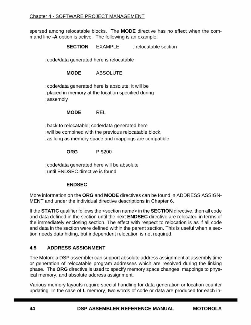
Chapter 4 - SOFTWARE PROJECT MANAGEMENT
44 DSP ASSEMBLER REFERENCE MANUAL MOTOROLA
spersed among relocatable blocks. The MODE directive has no effect when the com-mand line -A option is active. The following is an example:
SECTION EXAMPLE ; relocatable section
; code/data generated here is relocatable
MODE ABSOLUTE
; code/data generated here is absolute; it will be; placed in memory at the location specified during; assembly
MODE REL
; back to relocatable; code/data generated here; will be combined with the previous relocatable block,; as long as memory space and mappings are compatible
ORG P:$200
; code/data generated here will be absolute; until ENDSEC directive is found
ENDSEC
More information on the ORG and MODE directives can be found in ADDRESS ASSIGN-MENT and under the individual directive descriptions in Chapter 6.
If the STATIC qualifier follows the <section name> in the SECTION directive, then all codeand data defined in the section until the next ENDSEC directive are relocated in terms ofthe immediately enclosing section. The effect with respect to relocation is as if all codeand data in the section were defined within the parent section. This is useful when a sec-tion needs data hiding, but independent relocation is not required.
4.5 ADDRESS ASSIGNMENT
The Motorola DSP assembler can support absolute address assignment at assembly timeor generation of relocatable program addresses which are resolved during the linkingphase. The ORG directive is used to specify memory space changes, mappings to phys-ical memory, and absolute address assignment.
Various memory layouts require special handling for data generation or location counterupdating. In the case of L memory, two words of code or data are produced for each in-
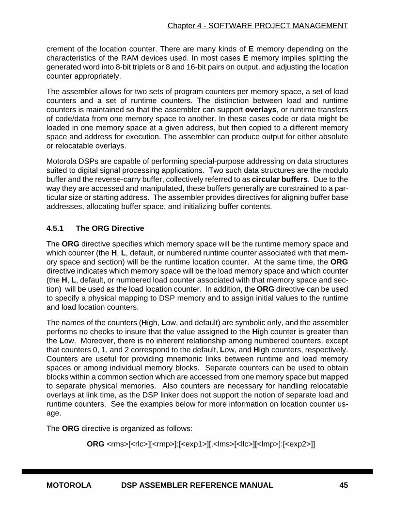
Chapter 4 - SOFTWARE PROJECT MANAGEMENT
MOTOROLA DSP ASSEMBLER REFERENCE MANUAL 45
crement of the location counter. There are many kinds of E memory depending on thecharacteristics of the RAM devices used. In most cases E memory implies splitting thegenerated word into 8-bit triplets or 8 and 16-bit pairs on output, and adjusting the locationcounter appropriately.
The assembler allows for two sets of program counters per memory space, a set of loadcounters and a set of runtime counters. The distinction between load and runtimecounters is maintained so that the assembler can support overlays , or runtime transfersof code/data from one memory space to another. In these cases code or data might beloaded in one memory space at a given address, but then copied to a different memoryspace and address for execution. The assembler can produce output for either absoluteor relocatable overlays.
Motorola DSPs are capable of performing special-purpose addressing on data structuressuited to digital signal processing applications. Two such data structures are the modulobuffer and the reverse-carry buffer, collectively referred to as circular buffers . Due to theway they are accessed and manipulated, these buffers generally are constrained to a par-ticular size or starting address. The assembler provides directives for aligning buffer baseaddresses, allocating buffer space, and initializing buffer contents.
4.5.1 The ORG Directive
The ORG directive specifies which memory space will be the runtime memory space andwhich counter (the H, L, default, or numbered runtime counter associated with that mem-ory space and section) will be the runtime location counter. At the same time, the ORGdirective indicates which memory space will be the load memory space and which counter(the H, L, default, or numbered load counter associated with that memory space and sec-tion) will be used as the load location counter. In addition, the ORG directive can be usedto specify a physical mapping to DSP memory and to assign initial values to the runtimeand load location counters.
The names of the counters (High, Low, and default) are symbolic only, and the assemblerperforms no checks to insure that the value assigned to the High counter is greater thanthe Low. Moreover, there is no inherent relationship among numbered counters, exceptthat counters 0, 1, and 2 correspond to the default, Low, and High counters, respectively.Counters are useful for providing mnemonic links between runtime and load memoryspaces or among individual memory blocks. Separate counters can be used to obtainblocks within a common section which are accessed from one memory space but mappedto separate physical memories. Also counters are necessary for handling relocatableoverlays at link time, as the DSP linker does not support the notion of separate load andruntime counters. See the examples below for more information on location counter us-age.
The ORG directive is organized as follows:
ORG <rms>[<rlc>][<rmp>]:[<exp1>][,<lms>[<llc>][<lmp>]:[<exp2>]]
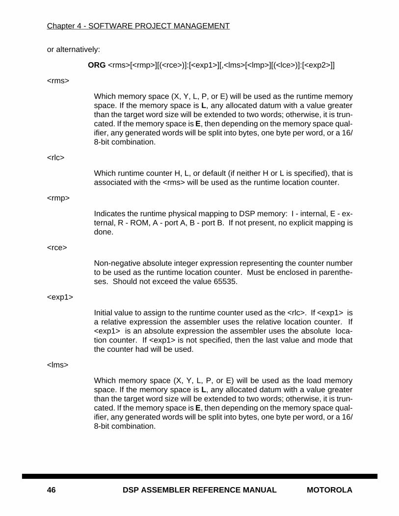
Chapter 4 - SOFTWARE PROJECT MANAGEMENT
46 DSP ASSEMBLER REFERENCE MANUAL MOTOROLA
or alternatively:
ORG <rms>[<rmp>][(<rce>)]:[<exp1>][,<lms>[<lmp>][(<lce>)]:[<exp2>]]
<rms>
Which memory space (X, Y, L, P, or E) will be used as the runtime memoryspace. If the memory space is L, any allocated datum with a value greaterthan the target word size will be extended to two words; otherwise, it is trun-cated. If the memory space is E, then depending on the memory space qual-ifier, any generated words will be split into bytes, one byte per word, or a 16/8-bit combination.
<rlc>
Which runtime counter H, L, or default (if neither H or L is specified), that isassociated with the <rms> will be used as the runtime location counter.
<rmp>
Indicates the runtime physical mapping to DSP memory: I - internal, E - ex-ternal, R - ROM, A - port A, B - port B. If not present, no explicit mapping isdone.
<rce>
Non-negative absolute integer expression representing the counter numberto be used as the runtime location counter. Must be enclosed in parenthe-ses. Should not exceed the value 65535.
<exp1>
Initial value to assign to the runtime counter used as the <rlc>. If <exp1> isa relative expression the assembler uses the relative location counter. If<exp1> is an absolute expression the assembler uses the absolute loca-tion counter. If <exp1> is not specified, then the last value and mode thatthe counter had will be used.
<lms>
Which memory space (X, Y, L, P, or E) will be used as the load memoryspace. If the memory space is L, any allocated datum with a value greaterthan the target word size will be extended to two words; otherwise, it is trun-cated. If the memory space is E, then depending on the memory space qual-ifier, any generated words will be split into bytes, one byte per word, or a 16/8-bit combination.
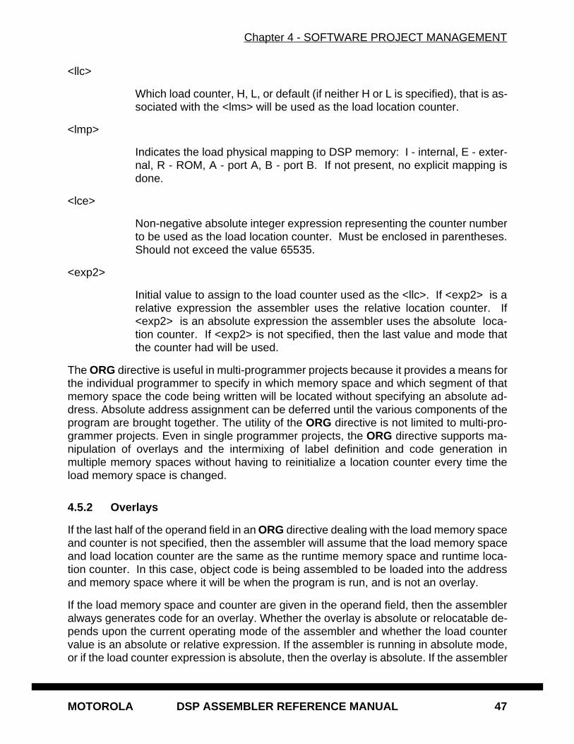
Chapter 4 - SOFTWARE PROJECT MANAGEMENT
MOTOROLA DSP ASSEMBLER REFERENCE MANUAL 47
<llc>
Which load counter, H, L, or default (if neither H or L is specified), that is as-sociated with the <lms> will be used as the load location counter.
<lmp>
Indicates the load physical mapping to DSP memory: I - internal, E - exter-nal, R - ROM, A - port A, B - port B. If not present, no explicit mapping isdone.
<lce>
Non-negative absolute integer expression representing the counter numberto be used as the load location counter. Must be enclosed in parentheses.Should not exceed the value 65535.
<exp2>
Initial value to assign to the load counter used as the <llc>. If <exp2> is arelative expression the assembler uses the relative location counter. If<exp2> is an absolute expression the assembler uses the absolute loca-tion counter. If <exp2> is not specified, then the last value and mode thatthe counter had will be used.
The ORG directive is useful in multi-programmer projects because it provides a means forthe individual programmer to specify in which memory space and which segment of thatmemory space the code being written will be located without specifying an absolute ad-dress. Absolute address assignment can be deferred until the various components of theprogram are brought together. The utility of the ORG directive is not limited to multi-pro-grammer projects. Even in single programmer projects, the ORG directive supports ma-nipulation of overlays and the intermixing of label definition and code generation inmultiple memory spaces without having to reinitialize a location counter every time theload memory space is changed.
4.5.2 Overlays
If the last half of the operand field in an ORG directive dealing with the load memory spaceand counter is not specified, then the assembler will assume that the load memory spaceand load location counter are the same as the runtime memory space and runtime loca-tion counter. In this case, object code is being assembled to be loaded into the addressand memory space where it will be when the program is run, and is not an overlay.
If the load memory space and counter are given in the operand field, then the assembleralways generates code for an overlay. Whether the overlay is absolute or relocatable de-pends upon the current operating mode of the assembler and whether the load countervalue is an absolute or relative expression. If the assembler is running in absolute mode,or if the load counter expression is absolute, then the overlay is absolute. If the assembler
Chapter 4 - SOFTWARE PROJECT MANAGEMENT
48 DSP ASSEMBLER REFERENCE MANUAL MOTOROLA
is in relative mode and the load counter expression is relative, the overlay is relocatable.Runtime relocatable overlay code is addressed relative to the location given in the runtimelocation counter expression. This expression, if relative, may not refer to another overlayblock. See section 1.6 for more information on location counters and overlays.
The values and memory space attributes of both the load and runtime location counterscan be accessed with the @LCV function (see Section 3.8). This is particularly usefulwhen assigning the load location counter value to a label as a reference point for the over-lay manager part of the program. The High, Low, default, or numbered counter assign-ment can be determined by using the @CTR function (Section 3.8).
4.5.3 Address Assignment Examples
Some examples of the ORG directive are as follows:
ORG P:$1000
Sets the runtime memory space to P. Selects the default runtime counter (counter0) associated with P space to use as the runtime location counter and initializes itto $1000. The load memory space is implied to be P, and the load location counteris assumed to be the same as the runtime location counter.
ORG PHE:
Sets the runtime memory space to P. Selects the H load counter (counter 2) as-sociated with P space to use as the runtime location counter. The H counter willnot be initialized, and its last value will be used. Code generated hereafter will bemapped to external (E) memory. The load memory space is implied to be P, andthe load location counter is assumed to be the same as the runtime locationcounter.
ORG PI:OVL1,Y:
Indicates code will be generated for an overlay. The runtime memory space is P,and the default counter is used as the runtime location counter. It will be reset tothe value of OVL1. If the assembler is in absolute mode via the -A command lineoption then OVL1 must be an absolute expression. If OVL1 is an absolute expres-sion the assembler uses the absolute runtime location counter. If OVL1 is a relo-catable value the assembler uses the relative runtime location counter. In this caseOVL1 must not itself be an overlay symbol (e.g. defined within an overlay block).The load memory space is Y. Since neither H, L, nor any counter expression wasspecified as the load counter, the default load counter (counter 0) will be used asthe load location counter. The counter value and mode will be whatever it was thelast time it was referenced.
Chapter 4 - SOFTWARE PROJECT MANAGEMENT
MOTOROLA DSP ASSEMBLER REFERENCE MANUAL 49
ORG XL:,E8:
Sets the runtime memory space to X. Selects the L counter (counter 1) associatedwith X space to use as the runtime location counter. The L counter will not be ini-tialized, and its last value will be used. The load memory space is set to E, and thequalifier 8 indicates a bytewise RAM configuration. Instructions and data will begenerated eight bits per output word with byte-oriented load addresses. The de-fault load counter will be used and there is no explicit load origin.
ORG P(5):,Y:$8000
Indicates code will be generated for an absolute overlay. The runtime memoryspace is P, and the counter used as the runtime location counter is counter 5. Itwill not be initialized, and the last previous value of counter 5 will be used. The loadmemory space is Y. Since neither H, L, nor any counter expression was specifiedas the load counter, the default load counter (counter 0) will be used as the loadlocation counter. The default load counter will be initialized to $8000.
If the last example shown was used in the following code sequence (assume the runtimecounter associated with P space had a previous value of $0010),
ORG P(5):,Y:$8000RLMUL MOVE X:(R0),D4.S Y:(R4),D7.S
FMPY.S D4,D7,D0MOVE D0.S,X:(R1)
then the label RLMUL would have a value of $0010 and a memory space attribute of Pspace; the code generated would load into Y memory starting at $8000; and the runtimeaddress associated with the code would start at $0010.
4.5.4 Circular Buffers
To take advantage of the special DSP addressing capabilities a circular buffer must bealigned on an appropriate address boundary with respect to its size. For a buffer to belocated properly in memory the lower bits of the starting address which encompass oneless than the buffer size must be zero. For example, the lowest address greater than zeroat which a buffer of size 32 may be located is 32 (20 hexadecimal). More generally, thebuffer base address must be modulo the buffer size, or a multiple of 2k, where 2k is greaterthan or equal to the size of the buffer.
Buffers may be allocated manually or by using one of the assembler’s special buffer di-rectives:
ORG X:$100BUF1 DS 24BUF2 DSM 32
Chapter 4 - SOFTWARE PROJECT MANAGEMENT
50 DSP ASSEMBLER REFERENCE MANUAL MOTOROLA
The ORG statement sets the origin to hexadecimal 100 in X memory. The first bufferBUF1 is manually allocated with a size of 24. Since the starting address is hex 100 thebuffer is already suitably aligned. The label BUF1 is assigned the runtime counter valueat the beginning of the buffer. The second buffer is allocated using the DSM directive,which automatically sets the buffer starting address before reserving space. In this case,the first buffer ended at location 117 hexadecimal, so the assembler advances the pro-gram counter to location 120 hex before assigning a value to the buffer label BUF2.
Buffers are special-purpose data structures, but they are named and accessed with labelslike any other data block. They therefore adhere to the same rules governing data hidingin sections that any other segment of code or data would follow. A buffer allocated whenthe assembler is in absolute mode (either via -A or an absolute ORG or MODE directive)is placed in memory according to the absolute value of the runtime location counter at as-sembly time. A buffer allocated in relative mode (a relocatable buffer ) is suitably alignedwithin its relocation section at assembly time. During the link phase a section enclosingany relocatable buffers is located based on the largest relocatable buffer it contains, un-less the buffers inside the section are auto-aligned. This insures that any smaller bufferswithin the section are properly aligned. If any buffers in the section are auto-aligned, theywill be relocated independent of any other code or data in the section. Note that reposi-tioning of any buffer, whether relocatable or absolute, may result in alignment gaps inmemory depending on the layout of data surrounding the buffer blocks.
4.6 EXAMPLE 1: MULTI-PROGRAMMER ENVIRONMENT
Typical multi-programmer projects are often split into tasks representing functional units.For discussion purposes, suppose a project has been divided into three tasks - I/O,FILTER, and MAIN. Each task will be written by a separate programmer as a separate
Chapter 4 - SOFTWARE PROJECT MANAGEMENT
MOTOROLA DSP ASSEMBLER REFERENCE MANUAL 51
section. For example, when the I/O task has been written, there will be a file calledIO.ASM. This file will have the following form:
SECTION I_OXREF I_PORT,O_PORTORG XL:..<storage location definitions>..ORG P:..<IO section source statements>..ENDSEC
In this example, because the X space storage locations were defined within the sectionI_O, they will be private storage locations that are accessible only by the I_O handler, andcannot be referenced by other sections. If global memory resource management is de-sired, then the I_O section would not have defined any storage locations, and these wouldhave been defined as XREF. The X space data will be addressed through the Lowruntime counter. The P memory code is also private to the I_O section and uses the de-fault runtime location counter for address generation.
In the discussion below, assume that the programmers responsible for the FILTER andMAIN sections have similar program structures located in files named FILTER.ASM andMAIN.ASM respectively. The program units can be combined either by invoking a finalassembly step to assign absolute addresses, or by assembling the modules separatelyand then linking.
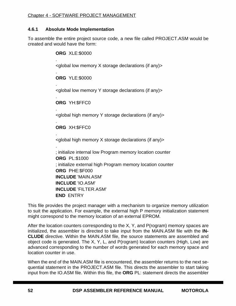
Chapter 4 - SOFTWARE PROJECT MANAGEMENT
52 DSP ASSEMBLER REFERENCE MANUAL MOTOROLA
4.6.1 Absolute Mode Implementation
To assemble the entire project source code, a new file called PROJECT.ASM would becreated and would have the form:
ORG XLE:$0000.<global low memory X storage declarations (if any)>.ORG YLE:$0000.<global low memory Y storage declarations (if any)>.ORG YH:$FFC0.<global high memory Y storage declarations (if any)>.ORG XH:$FFC0.<global high memory X storage declarations (if any)>.; initialize internal low Program memory location counterORG PL:$1000; initialize external high Program memory location counterORG PHE:$F000INCLUDE 'MAIN.ASM'INCLUDE 'IO.ASM'INCLUDE 'FILTER.ASM'END ENTRY
This file provides the project manager with a mechanism to organize memory utilizationto suit the application. For example, the external high P memory initialization statementmight correspond to the memory location of an external EPROM.
After the location counters corresponding to the X, Y, and P(rogram) memory spaces areinitialized, the assembler is directed to take input from the MAIN.ASM file with the IN-CLUDE directive. Within the MAIN.ASM file, the source statements are assembled andobject code is generated. The X, Y, L, and P(rogram) location counters (High, Low) areadvanced corresponding to the number of words generated for each memory space andlocation counter in use.
When the end of the MAIN.ASM file is encountered, the assembler returns to the next se-quential statement in the PROJECT.ASM file. This directs the assembler to start takinginput from the IO.ASM file. Within this file, the ORG PL: statement directs the assembler

Chapter 4 - SOFTWARE PROJECT MANAGEMENT
MOTOROLA DSP ASSEMBLER REFERENCE MANUAL 53
to set the current memory space to P(rogram) and restore the last used P(rogram) L(ow)location counter. The <IO source program statements> shown previously will be assem-bled at the next available Low Program memory space. When the end of the IO.ASM fileis encountered, the X, Y, and P(rogram) location counters (High and Low) will have beenadvanced corresponding to the number of words generated for each memory space.
In a similar manner, the file FILTER.ASM will be assembled. The last statement of thePROJECT.ASM file informs the assembler that this is the last logical source statement,and the starting address for the object module will be a label called ENTRY. In the exam-ple above, ENTRY would have been a label defined in the section MAIN and declared asglobal with the XDEF directive.
4.6.2 Relative Mode Implementation
Using the assembler default relative mode, each of the source files is assembled sepa-rately. For each section defined in the input files a separate set of location counters ismaintained such that all memory spaces for each section begin at relative address zero.The linker is invoked to combine the files and establish base addresses:
DSPLNK -B -M -OXLI:0 -OYLI:0 -OYH:FFC0 -OXH:FFC0 \-OPL:1000 -OPHE:A000 MAIN IO FILTER
The linker reads the command input and sets up base values for all counters specified onthe command line. In this example, the X and Y low memory counters are initialized to ze-ro, whereas the X and Y high memory counters are set to FFC0 hexadecimal. The pro-gram low and high memory counters are initialized similarly. When the linker creates theexecutable file it reads the input files and sets the starting address for all sections relativeto the values obtained from the command line. As the MAIN object file is read the linkerincrements the section counters for all appropriate memory spaces.
After the MAIN object file is processed, the IO object file is read. The section named I_Ocontained an ORG directive indicating a switch to the low X data memory counter. Recallthat the assembler generated relocatable code for the I_O section source such that thelow X data memory counter begins at zero. The linker adjusts the low X memory counterassociated with section I_O to reflect any previous data generation performed in low Xmemory (e.g. in MAIN). The FILTER module is linked in a similar fashion.
Another way for specifying base addresses, instead of lengthy command line options, isthrough a memory control file . The memory control file allows the programmer to indi-cate memory space starting addresses analogously to the command line approach. In ad-dition, the memory control file offers finer control over placement of sections in memory.See the Motorola DSP Linker/Librarian Reference Manual for more information on thememory control file.
The preceding examples described two methods for organizing a software project. Referto the descriptions of the ORG and SECTION directives in Chapter 6 for a more detaileddiscussion. See also the Motorola DSP Linker/Librarian Reference Manual for more in-
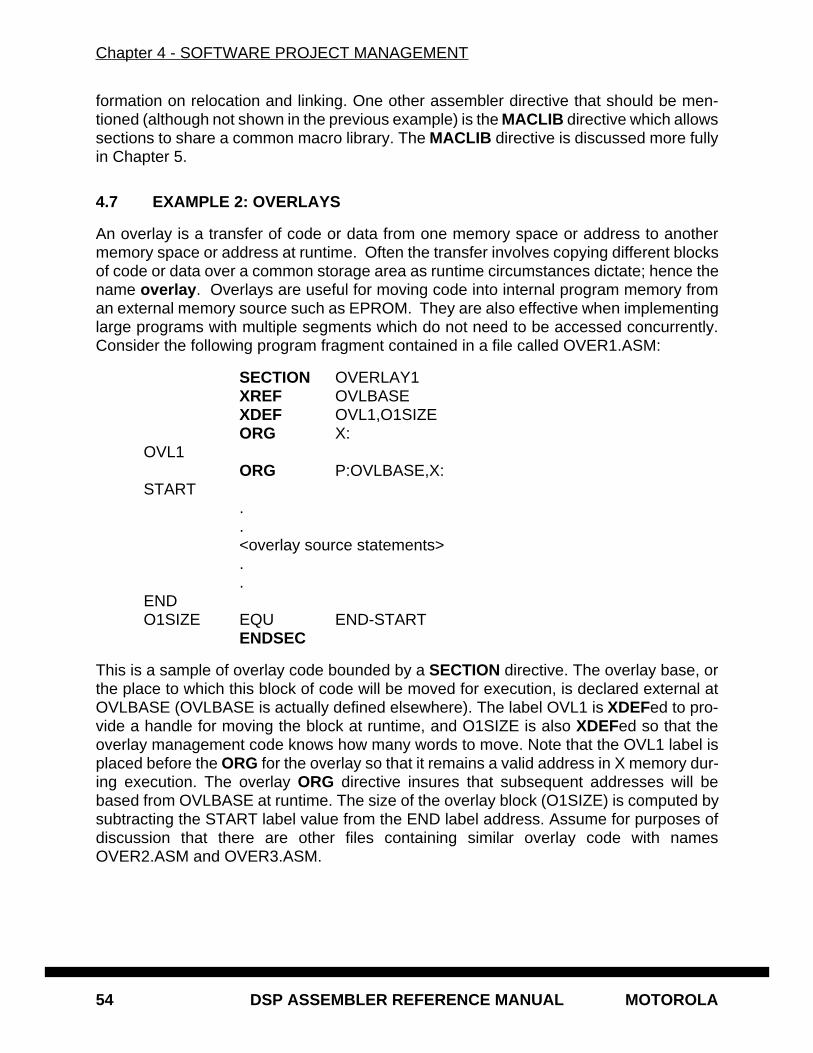
Chapter 4 - SOFTWARE PROJECT MANAGEMENT
54 DSP ASSEMBLER REFERENCE MANUAL MOTOROLA
formation on relocation and linking. One other assembler directive that should be men-tioned (although not shown in the previous example) is the MACLIB directive which allowssections to share a common macro library. The MACLIB directive is discussed more fullyin Chapter 5.
4.7 EXAMPLE 2: OVERLAYS
An overlay is a transfer of code or data from one memory space or address to anothermemory space or address at runtime. Often the transfer involves copying different blocksof code or data over a common storage area as runtime circumstances dictate; hence thename overlay . Overlays are useful for moving code into internal program memory froman external memory source such as EPROM. They are also effective when implementinglarge programs with multiple segments which do not need to be accessed concurrently.Consider the following program fragment contained in a file called OVER1.ASM:
SECTION OVERLAY1XREF OVLBASEXDEF OVL1,O1SIZEORG X:
OVL1ORG P:OVLBASE,X:
START..<overlay source statements>..
ENDO1SIZE EQU END-START
ENDSEC
This is a sample of overlay code bounded by a SECTION directive. The overlay base, orthe place to which this block of code will be moved for execution, is declared external atOVLBASE (OVLBASE is actually defined elsewhere). The label OVL1 is XDEFed to pro-vide a handle for moving the block at runtime, and O1SIZE is also XDEFed so that theoverlay management code knows how many words to move. Note that the OVL1 label isplaced before the ORG for the overlay so that it remains a valid address in X memory dur-ing execution. The overlay ORG directive insures that subsequent addresses will bebased from OVLBASE at runtime. The size of the overlay block (O1SIZE) is computed bysubtracting the START label value from the END label address. Assume for purposes ofdiscussion that there are other files containing similar overlay code with namesOVER2.ASM and OVER3.ASM.
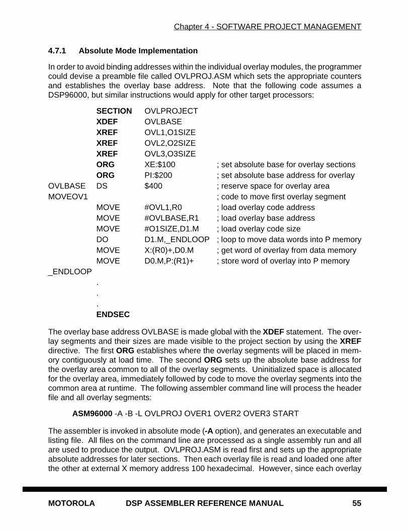
Chapter 4 - SOFTWARE PROJECT MANAGEMENT
MOTOROLA DSP ASSEMBLER REFERENCE MANUAL 55
4.7.1 Absolute Mode Implementation
In order to avoid binding addresses within the individual overlay modules, the programmercould devise a preamble file called OVLPROJ.ASM which sets the appropriate countersand establishes the overlay base address. Note that the following code assumes aDSP96000, but similar instructions would apply for other target processors:
SECTION OVLPROJECTXDEF OVLBASEXREF OVL1,O1SIZEXREF OVL2,O2SIZEXREF OVL3,O3SIZEORG XE:$100 ; set absolute base for overlay sectionsORG PI:$200 ; set absolute base address for overlay
OVLBASE DS $400 ; reserve space for overlay areaMOVEOV1 ; code to move first overlay segment
MOVE #OVL1,R0 ; load overlay code addressMOVE #OVLBASE,R1 ; load overlay base addressMOVE #O1SIZE,D1.M ; load overlay code sizeDO D1.M,_ENDLOOP ; loop to move data words into P memoryMOVE X:(R0)+,D0.M ; get word of overlay from data memoryMOVE D0.M,P:(R1)+ ; store word of overlay into P memory
_ENDLOOP...ENDSEC
The overlay base address OVLBASE is made global with the XDEF statement. The over-lay segments and their sizes are made visible to the project section by using the XREFdirective. The first ORG establishes where the overlay segments will be placed in mem-ory contiguously at load time. The second ORG sets up the absolute base address forthe overlay area common to all of the overlay segments. Uninitialized space is allocatedfor the overlay area, immediately followed by code to move the overlay segments into thecommon area at runtime. The following assembler command line will process the headerfile and all overlay segments:
ASM96000 -A -B -L OVLPROJ OVER1 OVER2 OVER3 START
The assembler is invoked in absolute mode (-A option), and generates an executable andlisting file. All files on the command line are processed as a single assembly run and allare used to produce the output. OVLPROJ.ASM is read first and sets up the appropriateabsolute addresses for later sections. Then each overlay file is read and loaded one afterthe other at external X memory address 100 hexadecimal. However, since each overlay
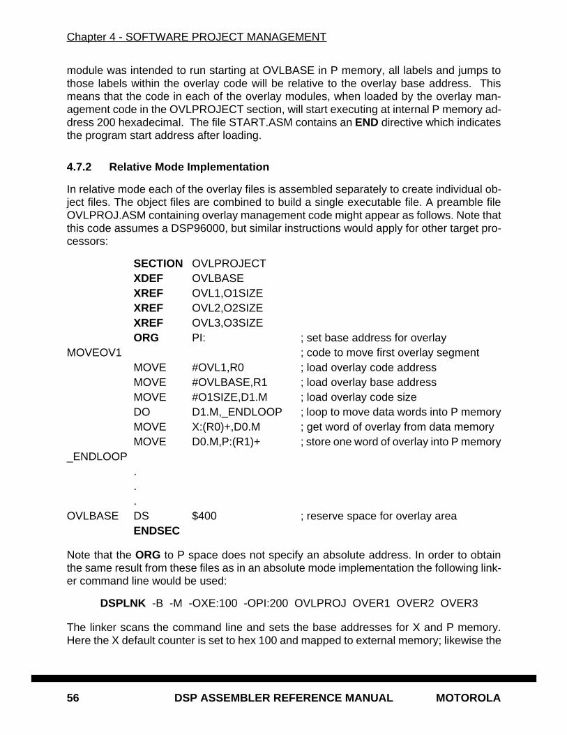
Chapter 4 - SOFTWARE PROJECT MANAGEMENT
56 DSP ASSEMBLER REFERENCE MANUAL MOTOROLA
module was intended to run starting at OVLBASE in P memory, all labels and jumps tothose labels within the overlay code will be relative to the overlay base address. Thismeans that the code in each of the overlay modules, when loaded by the overlay man-agement code in the OVLPROJECT section, will start executing at internal P memory ad-dress 200 hexadecimal. The file START.ASM contains an END directive which indicatesthe program start address after loading.
4.7.2 Relative Mode Implementation
In relative mode each of the overlay files is assembled separately to create individual ob-ject files. The object files are combined to build a single executable file. A preamble fileOVLPROJ.ASM containing overlay management code might appear as follows. Note thatthis code assumes a DSP96000, but similar instructions would apply for other target pro-cessors:
SECTION OVLPROJECTXDEF OVLBASEXREF OVL1,O1SIZEXREF OVL2,O2SIZEXREF OVL3,O3SIZEORG PI: ; set base address for overlay
MOVEOV1 ; code to move first overlay segmentMOVE #OVL1,R0 ; load overlay code addressMOVE #OVLBASE,R1 ; load overlay base addressMOVE #O1SIZE,D1.M ; load overlay code sizeDO D1.M,_ENDLOOP ; loop to move data words into P memoryMOVE X:(R0)+,D0.M ; get word of overlay from data memoryMOVE D0.M,P:(R1)+ ; store one word of overlay into P memory
_ENDLOOP...
OVLBASE DS $400 ; reserve space for overlay areaENDSEC
Note that the ORG to P space does not specify an absolute address. In order to obtainthe same result from these files as in an absolute mode implementation the following link-er command line would be used:
DSPLNK -B -M -OXE:100 -OPI:200 OVLPROJ OVER1 OVER2 OVER3
The linker scans the command line and sets the base addresses for X and P memory.Here the X default counter is set to hex 100 and mapped to external memory; likewise the
Chapter 4 - SOFTWARE PROJECT MANAGEMENT
MOTOROLA DSP ASSEMBLER REFERENCE MANUAL 57
P default counter is set to hex 200 and mapped to internal memory. Base addresses canalso be established with the linker memory control file.
The linker reads each input object file, placing the header file in internal P memory andcombining the overlay modules into a contiguous block loaded into external X memory atlocation 100 hexadecimal. Any labels or jumps within the overlay blocks are resolved toaddresses relative to the relocatable symbol OVLBASE. Since OVLBASE is the first loadP memory address it is assigned the value 200 hexadecimal. The linker does not guaran-tee that a given symbol or section will begin at a particular location unless that informationis explicitly specified in the linker memory control file. For more information on specificlinker operations see the Motorola DSP Linker/Librarian Reference Manual .
4.8 EXAMPLE 3: BOOTSTRAP OVERLAY
Many Motorola DSP processors, specifically those with RAM-based program memory,support a bootstrap mode of operation. This involves mapping a built-in ROM-based boot-strap program into P memory, executing the program to move user-supplied code fromanother location (usually EPROM) into program RAM, then transferring control to the userprogram. Because the user program is loaded in one location (e.g. EPROM) but movedto another for execution, it is a natural application for assembly language overlay seman-tics. Another wrinkle in bootstrap mode is that user instruction words are loaded in byte-wise fashion, such that the load location counter must be incremented by bytes rather
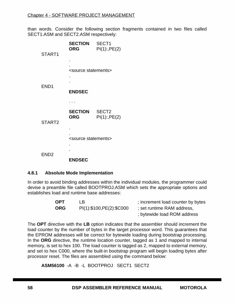
Chapter 4 - SOFTWARE PROJECT MANAGEMENT
58 DSP ASSEMBLER REFERENCE MANUAL MOTOROLA
than words. Consider the following section fragments contained in two files calledSECT1.ASM and SECT2.ASM respectively:
SECTION SECT1ORG PI(1):,PE(2)
START1..<source statements>..
END1ENDSEC
. . .
SECTION SECT2ORG PI(1):,PE(2)
START2..<source statements>..
END2ENDSEC
4.8.1 Absolute Mode Implementation
In order to avoid binding addresses within the individual modules, the programmer coulddevise a preamble file called BOOTPROJ.ASM which sets the appropriate options andestablishes load and runtime base addresses:
OPT LB ; increment load counter by bytesORG PI(1):$100,PE(2):$C000 ; set runtime RAM address,
; bytewide load ROM address
The OPT directive with the LB option indicates that the assembler should increment theload counter by the number of bytes in the target processor word. This guarantees thatthe EPROM addresses will be correct for bytewide loading during bootstrap processing.In the ORG directive, the runtime location counter, tagged as 1 and mapped to internalmemory, is set to hex 100. The load counter is tagged as 2, mapped to external memory,and set to hex C000, where the built-in bootstrap program will begin loading bytes afterprocessor reset. The files are assembled using the command below:
ASM56100 -A -B -L BOOTPROJ SECT1 SECT2
Chapter 4 - SOFTWARE PROJECT MANAGEMENT
MOTOROLA DSP ASSEMBLER REFERENCE MANUAL 59
The assembler is invoked in absolute mode (-A option), and generates an executable andlisting file. All files on the command line are processed as a single assembly run and allare used to produce the output. BOOTPROJ.ASM is read first and sets up the appropriateabsolute addresses for later sections. Since no explicit base address was given in the sec-tion files, both load and runtime addresses will continue from one section to the other, e.g.they will be contiguous. For example, if only two words of instruction were between eachof the START and END labels, the runtime value for END1 and START2 would be hex102. However, the load address of the code associated with these labels, assuming a 16bit target word size, would be C004 hexadecimal. Similarly, the runtime value for END2would be 104 hex and the corresponding load address would be C008 hexadecimal.
4.8.2 Relative Mode Implementation
In relative mode each of the source files is assembled separately to create individual ob-ject files. The object files are combined to build a single executable file. A preamble file isnot necessary to handle bootstrap files in relative mode because the addresses are es-tablished at link time. In order to generate bytewide load addresses the LB option can bespecified on the assembler command line using the -O command line option:
ASM56100 -B -L -OLB SECT1
This command assembles the file SECT1.ASM and creates a relocatable object file calledSECT1.CLN. The listing file shows that the starting address of the section is zero; howev-er, because of the LB option on the command line the load counter will increment at twicethe rate of the runtime counter (assuming a 16 bit DSP56100 family target processor). Asimilar command is used to assemble the SECT2 module. The two files are linked as fol-lows:
DSPLNK -BBOOTPROJ.CLD "-OPI(1):100" "-OPE(2):C000" SECT1 SECT2
The linker scans the command line and sets the base addresses for P internal and exter-nal memory. The quotes around the -O options are necessary to avoid interpretation ofparentheses by some host command interpreters. Here the P counter number 1 is set tohex 100 and mapped to internal memory; likewise the P counter number 2 is set to hexC000 and mapped to external memory. Base addresses can also be established with thelinker memory control file. Since no explicit overlay base addresses were encountered inthe source files, both load and runtime addresses for the sections will be adjacent andnon-overlapping. Assuming a code size of 2 for each section and a 16 bit word size, thevalue for label START1 will be hex 100 and the value for START2 will be hex 102; thecorresponding load addresses will be C000 hex and C004 hex, respectively. The execut-able output will be written to the file BOOTPROJ.CLD.

Chapter 4 - SOFTWARE PROJECT MANAGEMENT
60 DSP ASSEMBLER REFERENCE MANUAL MOTOROLA
MOTOROLA DSP ASSEMBLER REFERENCE MANUAL 61
Chapter 5MACRO OPERATIONS AND CONDITIONAL ASSEMBLY
5.1 MACRO OPERATIONS
Programming applications frequently involve the coding of a repeated pattern or group ofinstructions. Some patterns contain variable entries which change for each repetition ofthe pattern. Others are subject to conditional assembly for a given occurrence of the in-struction group. In either case, macros provide a shorthand notation for handling theseinstruction patterns. Having determined the iterated pattern, the programmer can, withinthe macro, designate selected fields of any statement as variable. Thereafter by invokinga macro the programmer can use the entire pattern as many times as needed, substitutingdifferent parameters for the designated variable portions of the statements.
When the pattern is defined it is given a name. This name becomes the mnemonic bywhich the macro is subsequently invoked (called). If the name of the macro is the sameas an existing assembler directive or mnemonic opcode, the macro will replace the direc-tive or mnemonic opcode, and a warning will be issued. The warning can be avoided bythe use of the RDIRECT directive, which is used to remove entries from the assembler’sdirective and mnemonic tables. If directives or mnemonics are removed from the assem-bler’s tables, then no warning will be issued when the assembler processes macroswhose names are the same as the removed directive or mnemonic entries. However, ifa macro is defined through the MACLIB directive which has the same name as an existingdirective or opcode, it will not automatically replace that directive or opcode as previouslydescribed. In this case, the RDIRECT directive must be used to force the replacement.See the description of the MACLIB directive below.
The macro call causes source statements to be generated. The generated statementsmay contain substitutable arguments. The statements produced by a macro call are rel-atively unrestricted as to type. They can be any processor instruction, almost any assem-bler directive, or any previously-defined macro. Source statements resulting from amacro call are subject to the same conditions and restrictions that are applied to state-ments written by the programmer.
To invoke a macro, the macro name must appear in the operation code field of a sourcestatement. Any arguments are placed in the operand field. By suitably selecting the ar-guments in relation to their use as indicated by the macro definition, the programmercauses the assembler to produce in-line coding variations of the macro definition.
Chapter 5 - MACRO OPERATIONS AND CONDITIONAL ASSEMBLY
62 DSP ASSEMBLER REFERENCE MANUAL MOTOROLA
The effect of a macro call is to produce in-line code to perform a predefined function. Thecode is inserted in the normal flow of the program so that the generated instructions areexecuted with the rest of the program each time the macro is called.
An important feature in defining a macro is the use of macro calls within the macro defini-tion. The assembler processes such nested macro calls at expansion time only. Thenesting of one macro definition within another definition is permitted. However, the nestedmacro definition will not be processed until the primary macro is expanded. The macromust be defined before its appearance in a source statement operation field.
5.2 MACRO LIBRARIES
The Motorola DSP assembler allows for the maintenance of macro libraries with the MA-CLIB directive. This directive is used to specify the pathname (as defined by the host op-erating system) of a directory that contains macro definitions. Each macro definition mustbe in a separate file, and the file must be named the same as the macro with the extension.ASM added. For example, BLOCKMV.ASM would be a file that contained the definitionof the macro called BLOCKMV.
If a MACLIB directive has been specified in the source code and the assembler encoun-ters a name in the operation field that is not a previously defined macro or is not containedin the directive or mnemonic tables, the directory specified in the MACLIB directive will besearched for a file of that name (with the .ASM extension added). If such a file is found,the current source line will be saved, and the file will be opened for input as an INCLUDEfile. When the end of the file is encountered, the source line is restored and processingis resumed.
Because the source line is restored, the processed file must have a macro definition ofthe unknown name, or an error will result when the source line is restored and processed.However, the processed file is not limited to macro definitions, and can include any legalsource code statements. Multiple MACLIB directives may be given, in which case the as-sembler will search each directory in the order in which they were specified.
5.3 MACRO DEFINITION
The definition of a macro consists of three parts: the header, which assigns a name to themacro and defines the dummy arguments; the body, which consists of prototype or skel-eton source statements; and the terminator. The header is the MACRO directive, its label,and the dummy argument list. The body contains the pattern of standard source state-ments. The terminator is the ENDM directive.
The header of a macro definition has the form:
<label> MACRO [<dummy argument list>] [<comment>]
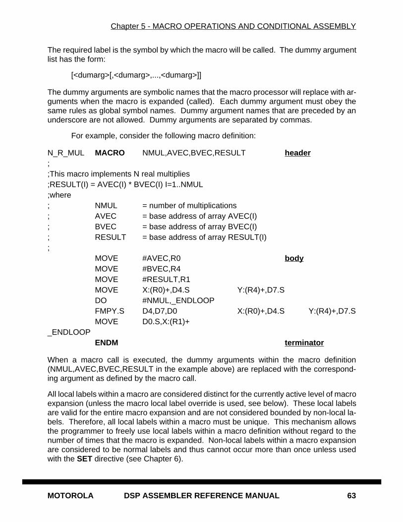
Chapter 5 - MACRO OPERATIONS AND CONDITIONAL ASSEMBLY
MOTOROLA DSP ASSEMBLER REFERENCE MANUAL 63
The required label is the symbol by which the macro will be called. The dummy argumentlist has the form:
[<dumarg>[,<dumarg>,...,<dumarg>]]
The dummy arguments are symbolic names that the macro processor will replace with ar-guments when the macro is expanded (called). Each dummy argument must obey thesame rules as global symbol names. Dummy argument names that are preceded by anunderscore are not allowed. Dummy arguments are separated by commas.
For example, consider the following macro definition:
N_R_MUL MACRO NMUL,AVEC,BVEC,RESULT header;;This macro implements N real multiplies;RESULT(I) = AVEC(I) * BVEC(I) I=1..NMUL;where; NMUL = number of multiplications; AVEC = base address of array AVEC(I); BVEC = base address of array BVEC(I); RESULT = base address of array RESULT(I);
MOVE #AVEC,R0 bodyMOVE #BVEC,R4MOVE #RESULT,R1MOVE X:(R0)+,D4.S Y:(R4)+,D7.SDO #NMUL,_ENDLOOPFMPY.S D4,D7,D0 X:(R0)+,D4.S Y:(R4)+,D7.SMOVE D0.S,X:(R1)+
_ENDLOOPENDM terminator
When a macro call is executed, the dummy arguments within the macro definition(NMUL,AVEC,BVEC,RESULT in the example above) are replaced with the correspond-ing argument as defined by the macro call.
All local labels within a macro are considered distinct for the currently active level of macroexpansion (unless the macro local label override is used, see below). These local labelsare valid for the entire macro expansion and are not considered bounded by non-local la-bels. Therefore, all local labels within a macro must be unique. This mechanism allowsthe programmer to freely use local labels within a macro definition without regard to thenumber of times that the macro is expanded. Non-local labels within a macro expansionare considered to be normal labels and thus cannot occur more than once unless usedwith the SET directive (see Chapter 6).
Chapter 5 - MACRO OPERATIONS AND CONDITIONAL ASSEMBLY
64 DSP ASSEMBLER REFERENCE MANUAL MOTOROLA
When specifying a local label within the body of a macro, the programmer must be awarethat the label symbol is valid for the entire body of the current level of macro expansion.It is not valid for any nested macros within the current level of expansion. The exampleabove shows why the local label feature is useful. If the macro N_R_MUL were calledseveral times, there would be several _ENDLOOP labels resulting from the macro expan-sions. This is acceptable because each _ENDLOOP label is considered private to a par-ticular instance of macro expansion.
It is sometimes desirable to pass local labels as macro arguments to be used within themacro as address references (e.g. MOVE #_LABEL,R0). The assembler effectively dis-allows this, however, since underscore label references within a macro invocation are re-garded as labels local to that expansion of the macro. A macro local label override isprovided which causes local symbol lookup to have normal scope rather than macro callscope. If a circumflex (^ ) precedes an expression containing an underscore label, at ex-pansion the associated term will be evaluated using the normal local label list rather thanthe macro local label list. The operator has no effect on normal labels or outside a macroexpansion.
5.4 MACRO CALLS
When a macro is invoked the statement causing the action is termed a macro call . Thesyntax of a macro call consists of the following fields:
[<label>] <macro name> [<arguments>] [<comment>]
The argument field can have the form:
[<arg>[,<arg>,...,<arg>]]
The macro call statement is made up of three fields besides the comment field: the <la-bel>, if any, will correspond to the value of the location counter at the start of the macroexpansion; the operation field which contains the macro name; and the operand fieldwhich contains substitutable arguments. Within the operand field each calling argumentof a macro call corresponds one-to-one with a dummy argument of the macro definition.For example, the N_R_MUL macro defined earlier could be invoked for expansion (called)by the statement:
N_R_MUL CNT+1,VEC1,VEC2,OUT
where the operand field arguments, separated by commas and taken left to right, corre-spond to the dummy arguments "N" through "RESULT", respectively. These argumentsare then substituted in their corresponding positions of the definition to produce a se-quence of instructions.
Macro arguments consist of sequences of characters separated by commas. Althoughthese can be specified as quoted strings, to simplify coding the assembler does not re-quire single quotes around macro argument strings. However, if an argument has an em-bedded comma or space, that argument must be surrounded by single quotes ('). An
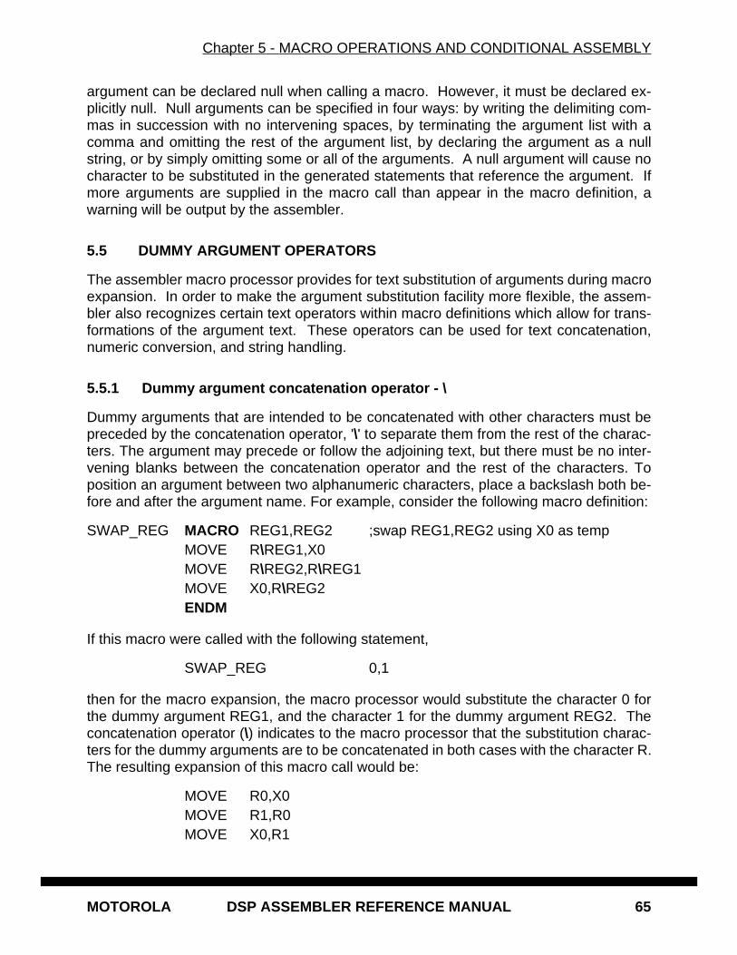
Chapter 5 - MACRO OPERATIONS AND CONDITIONAL ASSEMBLY
MOTOROLA DSP ASSEMBLER REFERENCE MANUAL 65
argument can be declared null when calling a macro. However, it must be declared ex-plicitly null. Null arguments can be specified in four ways: by writing the delimiting com-mas in succession with no intervening spaces, by terminating the argument list with acomma and omitting the rest of the argument list, by declaring the argument as a nullstring, or by simply omitting some or all of the arguments. A null argument will cause nocharacter to be substituted in the generated statements that reference the argument. Ifmore arguments are supplied in the macro call than appear in the macro definition, awarning will be output by the assembler.
5.5 DUMMY ARGUMENT OPERATORS
The assembler macro processor provides for text substitution of arguments during macroexpansion. In order to make the argument substitution facility more flexible, the assem-bler also recognizes certain text operators within macro definitions which allow for trans-formations of the argument text. These operators can be used for text concatenation,numeric conversion, and string handling.
5.5.1 Dummy argument concatenation operator - \
Dummy arguments that are intended to be concatenated with other characters must bepreceded by the concatenation operator, '\' to separate them from the rest of the charac-ters. The argument may precede or follow the adjoining text, but there must be no inter-vening blanks between the concatenation operator and the rest of the characters. Toposition an argument between two alphanumeric characters, place a backslash both be-fore and after the argument name. For example, consider the following macro definition:
SWAP_REG MACRO REG1,REG2 ;swap REG1,REG2 using X0 as tempMOVE R\REG1,X0MOVE R\REG2,R\REG1MOVE X0,R\REG2ENDM
If this macro were called with the following statement,
SWAP_REG 0,1
then for the macro expansion, the macro processor would substitute the character 0 forthe dummy argument REG1, and the character 1 for the dummy argument REG2. Theconcatenation operator (\) indicates to the macro processor that the substitution charac-ters for the dummy arguments are to be concatenated in both cases with the character R.The resulting expansion of this macro call would be:
MOVE R0,X0MOVE R1,R0MOVE X0,R1
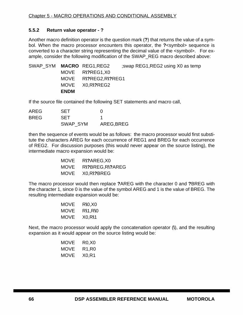
Chapter 5 - MACRO OPERATIONS AND CONDITIONAL ASSEMBLY
66 DSP ASSEMBLER REFERENCE MANUAL MOTOROLA
5.5.2 Return value operator - ?
Another macro definition operator is the question mark (?) that returns the value of a sym-bol. When the macro processor encounters this operator, the ?<symbol> sequence isconverted to a character string representing the decimal value of the <symbol>. For ex-ample, consider the following modification of the SWAP_REG macro described above:
SWAP_SYM MACRO REG1,REG2 ;swap REG1,REG2 using X0 as tempMOVE R\?REG1,X0MOVE R\?REG2,R\?REG1MOVE X0,R\?REG2ENDM
If the source file contained the following SET statements and macro call,
AREG SET 0BREG SET 1
SWAP_SYM AREG,BREG
then the sequence of events would be as follows: the macro processor would first substi-tute the characters AREG for each occurrence of REG1 and BREG for each occurrenceof REG2. For discussion purposes (this would never appear on the source listing), theintermediate macro expansion would be:
MOVE R\?AREG,X0MOVE R\?BREG,R\?AREGMOVE X0,R\?BREG
The macro processor would then replace ?AREG with the character 0 and ?BREG withthe character 1, since 0 is the value of the symbol AREG and 1 is the value of BREG. Theresulting intermediate expansion would be:
MOVE R\0,X0 MOVE R\1,R\0
MOVE X0,R\1
Next, the macro processor would apply the concatenation operator (\), and the resultingexpansion as it would appear on the source listing would be:
MOVE R0,X0MOVE R1,R0MOVE X0,R1
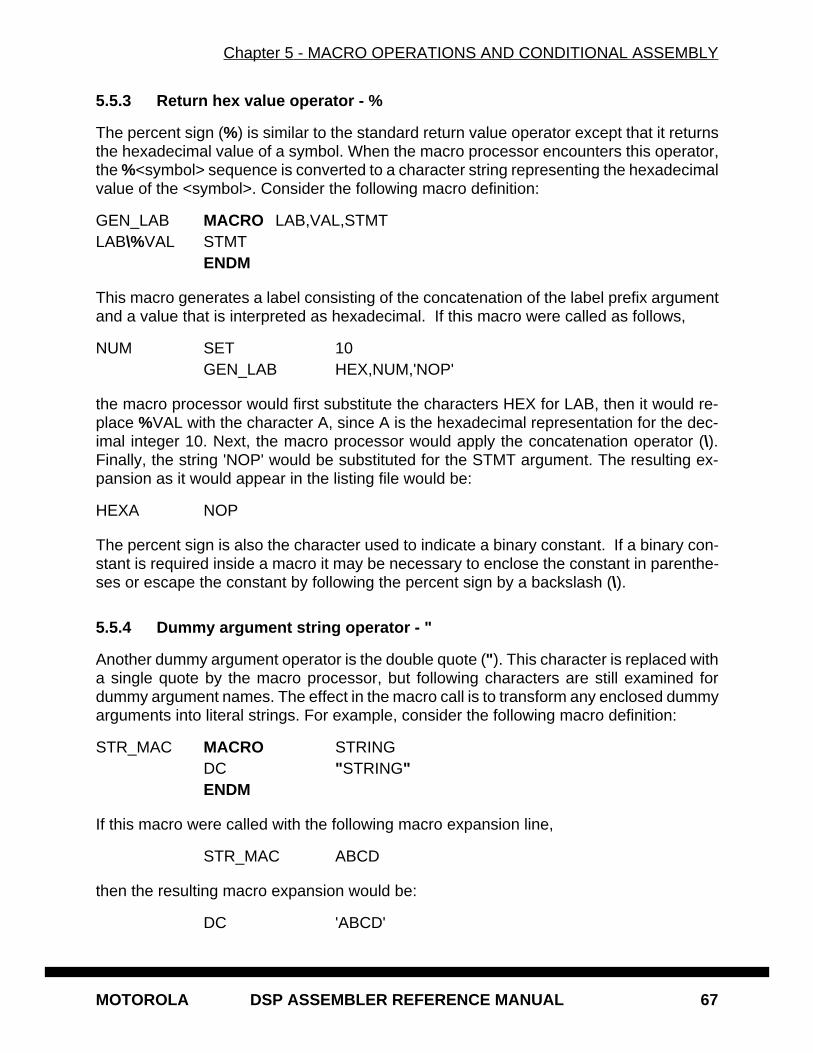
Chapter 5 - MACRO OPERATIONS AND CONDITIONAL ASSEMBLY
MOTOROLA DSP ASSEMBLER REFERENCE MANUAL 67
5.5.3 Return hex value operator - %
The percent sign (%) is similar to the standard return value operator except that it returnsthe hexadecimal value of a symbol. When the macro processor encounters this operator,the %<symbol> sequence is converted to a character string representing the hexadecimalvalue of the <symbol>. Consider the following macro definition:
GEN_LAB MACRO LAB,VAL,STMTLAB\%VAL STMT
ENDM
This macro generates a label consisting of the concatenation of the label prefix argumentand a value that is interpreted as hexadecimal. If this macro were called as follows,
NUM SET 10GEN_LAB HEX,NUM,'NOP'
the macro processor would first substitute the characters HEX for LAB, then it would re-place %VAL with the character A, since A is the hexadecimal representation for the dec-imal integer 10. Next, the macro processor would apply the concatenation operator (\).Finally, the string 'NOP' would be substituted for the STMT argument. The resulting ex-pansion as it would appear in the listing file would be:
HEXA NOP
The percent sign is also the character used to indicate a binary constant. If a binary con-stant is required inside a macro it may be necessary to enclose the constant in parenthe-ses or escape the constant by following the percent sign by a backslash (\).
5.5.4 Dummy argument string operator - "
Another dummy argument operator is the double quote (" ). This character is replaced witha single quote by the macro processor, but following characters are still examined fordummy argument names. The effect in the macro call is to transform any enclosed dummyarguments into literal strings. For example, consider the following macro definition:
STR_MAC MACRO STRINGDC "STRING"ENDM
If this macro were called with the following macro expansion line,
STR_MAC ABCD
then the resulting macro expansion would be:
DC 'ABCD'
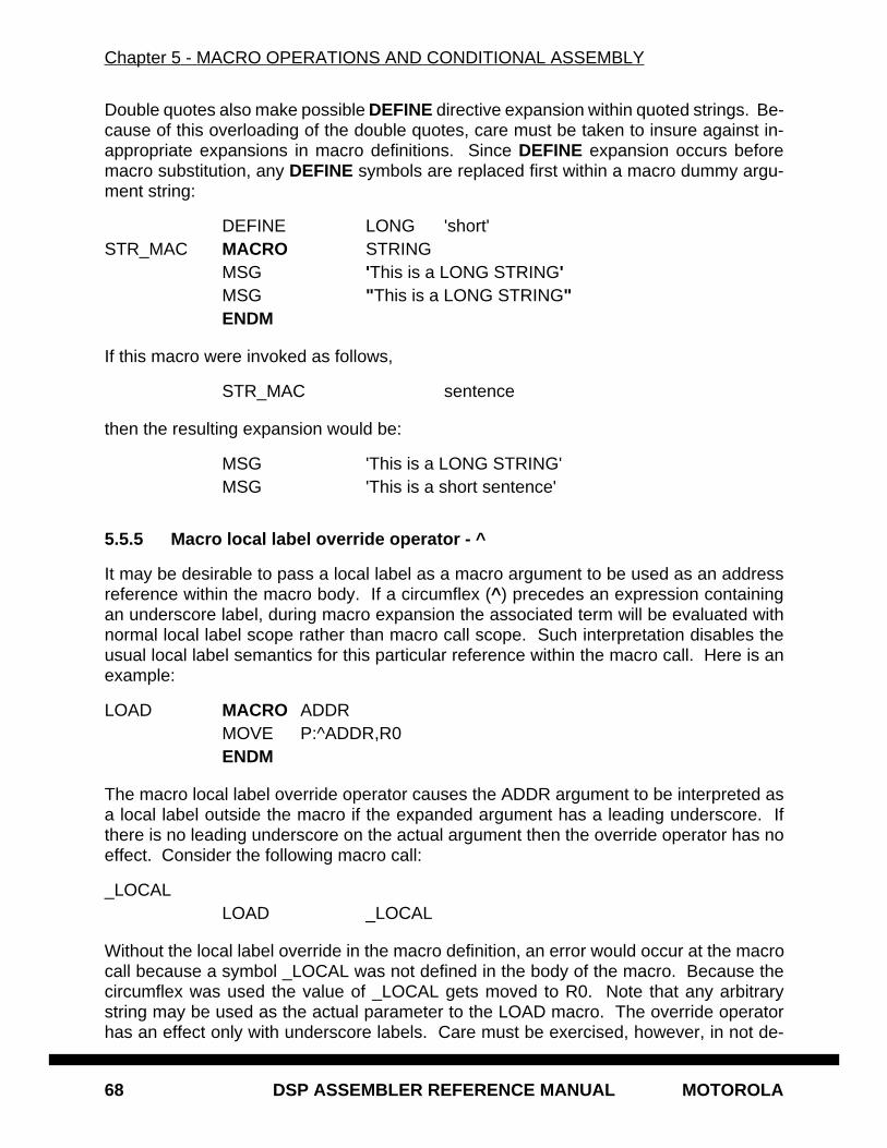
Chapter 5 - MACRO OPERATIONS AND CONDITIONAL ASSEMBLY
68 DSP ASSEMBLER REFERENCE MANUAL MOTOROLA
Double quotes also make possible DEFINE directive expansion within quoted strings. Be-cause of this overloading of the double quotes, care must be taken to insure against in-appropriate expansions in macro definitions. Since DEFINE expansion occurs beforemacro substitution, any DEFINE symbols are replaced first within a macro dummy argu-ment string:
DEFINE LONG 'short'STR_MAC MACRO STRING
MSG 'This is a LONG STRING'MSG "This is a LONG STRING"ENDM
If this macro were invoked as follows,
STR_MAC sentence
then the resulting expansion would be:
MSG 'This is a LONG STRING'MSG 'This is a short sentence'
5.5.5 Macro local label override operator - ^
It may be desirable to pass a local label as a macro argument to be used as an addressreference within the macro body. If a circumflex (^ ) precedes an expression containingan underscore label, during macro expansion the associated term will be evaluated withnormal local label scope rather than macro call scope. Such interpretation disables theusual local label semantics for this particular reference within the macro call. Here is anexample:
LOAD MACRO ADDRMOVE P:^ADDR,R0ENDM
The macro local label override operator causes the ADDR argument to be interpreted asa local label outside the macro if the expanded argument has a leading underscore. Ifthere is no leading underscore on the actual argument then the override operator has noeffect. Consider the following macro call:
_LOCALLOAD _LOCAL
Without the local label override in the macro definition, an error would occur at the macrocall because a symbol _LOCAL was not defined in the body of the macro. Because thecircumflex was used the value of _LOCAL gets moved to R0. Note that any arbitrarystring may be used as the actual parameter to the LOAD macro. The override operatorhas an effect only with underscore labels. Care must be exercised, however, in not de-
Chapter 5 - MACRO OPERATIONS AND CONDITIONAL ASSEMBLY
MOTOROLA DSP ASSEMBLER REFERENCE MANUAL 69
fining a macro label called _LOCAL and attempting to reference it as in the above exam-ple. In that case the macro local label override operator prevents the assembler fromseeing the local label definition for that reference, and an error would result.
5.6 DUP, DUPA, DUPC, DUPF DIRECTIVES
The DUP, DUPA, DUPC, and DUPF directives are specialized macro forms. They can bethought of as a simultaneous definition and call of an unnamed macro. The source state-ments between the DUP, DUPA, DUPC, and DUPF directives and the ENDM directivefollow the same rules as macro definitions, including (in the case of DUPA, DUPC, andDUPF) the dummy operator characters described previously. For a detailed description ofthese directives, refer to Chapter 6.
5.7 CONDITIONAL ASSEMBLY
Conditional assembly facilitates the writing of comprehensive source programs that cancover many conditions. Assembly conditions may be specified through the use of argu-ments in the case of macros, and through definition of symbols via the DEFINE, SET, andEQU directives. Variations of parameters can then cause assembly of only those partsnecessary for the given conditions. The built-in functions of the assembler provide a ver-satile means of testing many conditions of the assembly environment (see Section 3.8 formore information on the assembler built-in functions).
Conditional directives can also be used within a macro definition to ensure at expansiontime that arguments fall within a range of allowable values. In this way macros becomeself-checking and can generate error messages to any desired level of detail.
The conditional assembly directive IF has the following form:
IF <expression>..[ELSE] (the ELSE directive is optional)..ENDIF
A section of a program that is to be conditionally assembled must be bounded by an IF-ENDIF directive pair. If the optional ELSE directive is not present, then the source state-ments following the IF directive and up to the next ENDIF directive will be included as partof the source file being assembled only if the <expression> had a nonzero result. If the<expression> has a value of zero, the source file will be assembled as if those statementsbetween the IF and the ENDIF directives were never encountered. If the ELSE directiveis present and <expression> has a nonzero result, then the statements between the IFand ELSE directives will be assembled, and the statements between the ELSE andENDIF directives will be skipped. Alternatively, if <expression> has a value of zero, then
Chapter 5 - MACRO OPERATIONS AND CONDITIONAL ASSEMBLY
70 DSP ASSEMBLER REFERENCE MANUAL MOTOROLA
the statements between the IF and ELSE directives will be skipped, and the statementsbetween the ELSE and ENDIF directives will be assembled.
MOTOROLA DSP ASSEMBLER REFERENCE MANUAL 71
Chapter 6ASSEMBLER SIGNIFICANT CHARACTERS AND DIRECTIVES
6.1 INTRODUCTION
This chapter describes the directives that are recognized by the Motorola DSP Assem-bler. The assembler directives are instructions to the assembler rather than instructionsto be directly translated into object code. In addition, this chapter describes special char-acters that are considered significant to the assembler.
6.2 ASSEMBLER SIGNIFICANT CHARACTERS
There are several one and two character sequences that are significant to the assembler.Some have multiple meanings depending on the context in which they are used. Specialcharacters associated with expression evaluation are described in Chapter 3. Other as-sembler-significant characters are:
; - Comment delimiter;; - Unreported comment delimiter\ - Line continuation character or
Macro dummy argument concatenation operator? - Macro value substitution operator% - Macro hex value substitution operator^ - Macro local label override operator" - Macro string delimiter or
Quoted string DEFINE expansion character@ - Function delimiter* - Location counter substitution++ - String concatenation operator[ ] - Substring delimiter<< - I/O short addressing mode force operator< - Short addressing mode force operator> - Long addressing mode force operator# - Immediate addressing mode operator
Chapter 6 - ASSEMBLER SIGNIFICANT CHARACTERS AND DIRECTIVES
72 DSP ASSEMBLER REFERENCE MANUAL MOTOROLA
#< - Immediate short addressing mode force operator#> - Immediate long addressing mode force operator
6.3 ASSEMBLER DIRECTIVES
Assembler directives can be grouped by function into seven types:
1. Assembly control2. Symbol definition3. Data definition/storage allocation4. Listing control and options5. Object file control6. Macros and conditional assembly7. Structured programming
6.3.1 Assembly Control
The directives used for assembly control are:
COMMENT - Start comment linesDEFINE - Define substitution stringEND - End of source programFAIL - Programmer generated error messageFORCE - Set operand forcing modeHIMEM - Set high memory boundsINCLUDE - Include secondary fileLOMEM - Set low memory boundsMODE - Change relocation modeMSG - Programmer generated messageORG - Initialize memory space and location countersRADIX - Change input radix for constantsRDIRECT - Remove directive or mnemonic from tableSCSJMP - Set structured control branching modeSCSREG - Reassign structured control statement registersUNDEF - Undefine DEFINE symbolWARN - Programmer generated warning
Chapter 6 - ASSEMBLER SIGNIFICANT CHARACTERS AND DIRECTIVES
MOTOROLA DSP ASSEMBLER REFERENCE MANUAL 73
6.3.2 Symbol Definition
The directives used to control symbol definition are:
ENDSEC - End sectionEQU - Equate symbol to a valueGLOBAL - Global section symbol declarationGSET - Set global symbol to a valueLOCAL - Local section symbol declarationSECTION - Start sectionSET - Set symbol to a valueXDEF - External section symbol definitionXREF - External section symbol reference
6.3.3 Data Definition/Storage Allocation
The directives used to control constant data definition and storage allocation are:
BADDR - Set buffer addressBSB - Block storage bit-reverseBSC - Block storage of constantBSM - Block storage moduloBUFFER - Start bufferDC - Define constantDCB - Define constant byteDS - Define storageDSM - Define modulo storageDSR - Define reverse carry storageENDBUF - End buffer
6.3.4 Listing Control and Options
The directives used to control the output listing are:
LIST - List the assemblyLSTCOL - Set listing field widthsNOLIST - Stop assembly listingOPT - Assembler optionsPAGE - Top of page/size pagePRCTL - Send control string to printerSTITLE - Initialize program subtitleTABS - Set listing tab stopsTITLE - Initialize program title
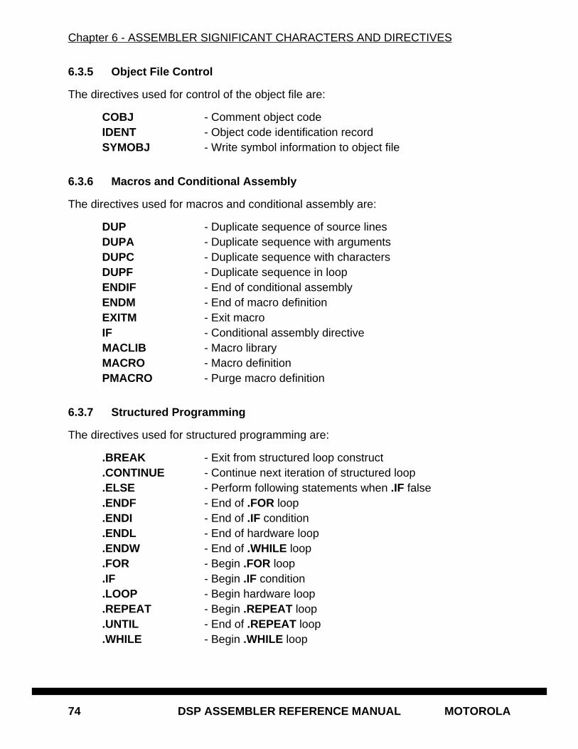
Chapter 6 - ASSEMBLER SIGNIFICANT CHARACTERS AND DIRECTIVES
74 DSP ASSEMBLER REFERENCE MANUAL MOTOROLA
6.3.5 Object File Control
The directives used for control of the object file are:
COBJ - Comment object codeIDENT - Object code identification recordSYMOBJ - Write symbol information to object file
6.3.6 Macros and Conditional Assembly
The directives used for macros and conditional assembly are:
DUP - Duplicate sequence of source linesDUPA - Duplicate sequence with argumentsDUPC - Duplicate sequence with charactersDUPF - Duplicate sequence in loopENDIF - End of conditional assemblyENDM - End of macro definitionEXITM - Exit macroIF - Conditional assembly directiveMACLIB - Macro libraryMACRO - Macro definitionPMACRO - Purge macro definition
6.3.7 Structured Programming
The directives used for structured programming are:
.BREAK - Exit from structured loop construct
.CONTINUE - Continue next iteration of structured loop
.ELSE - Perform following statements when .IF false
.ENDF - End of .FOR loop
.ENDI - End of .IF condition
.ENDL - End of hardware loop
.ENDW - End of .WHILE loop
.FOR - Begin .FOR loop
.IF - Begin .IF condition
.LOOP - Begin hardware loop
.REPEAT - Begin .REPEAT loop
.UNTIL - End of .REPEAT loop
.WHILE - Begin .WHILE loop

Chapter 6 - ASSEMBLER SIGNIFICANT CHARACTERS AND DIRECTIVES
MOTOROLA DSP ASSEMBLER REFERENCE MANUAL 75
Individual descriptions of each of the assembler special characters and directives follow.They include usage guidelines, functional descriptions, and examples. Some directivesrequire a label field, while in many cases a label is optional. If the description of an as-sembler directive does not indicate a mandatory or optional label field, then a label is notallowed on the same line as the directive. Structured programming directives are dis-cussed separately in Chapter 7.
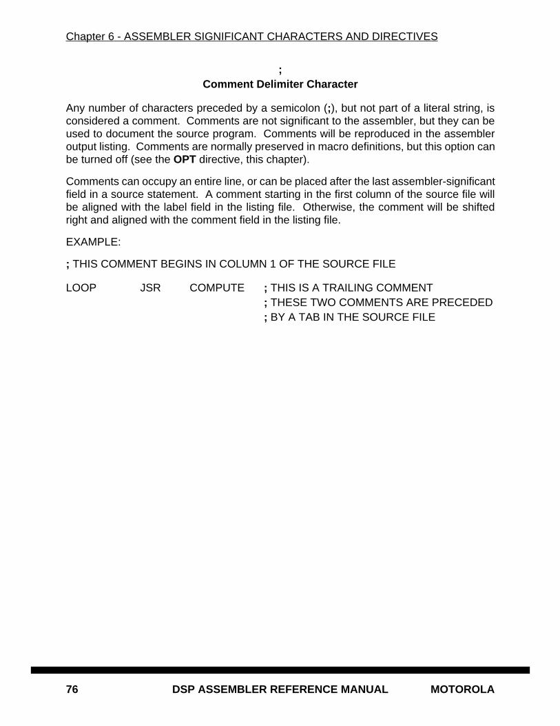
Chapter 6 - ASSEMBLER SIGNIFICANT CHARACTERS AND DIRECTIVES
76 DSP ASSEMBLER REFERENCE MANUAL MOTOROLA
;Comment Delimiter Character
Any number of characters preceded by a semicolon (;), but not part of a literal string, isconsidered a comment. Comments are not significant to the assembler, but they can beused to document the source program. Comments will be reproduced in the assembleroutput listing. Comments are normally preserved in macro definitions, but this option canbe turned off (see the OPT directive, this chapter).
Comments can occupy an entire line, or can be placed after the last assembler-significantfield in a source statement. A comment starting in the first column of the source file willbe aligned with the label field in the listing file. Otherwise, the comment will be shiftedright and aligned with the comment field in the listing file.
EXAMPLE:
; THIS COMMENT BEGINS IN COLUMN 1 OF THE SOURCE FILE
LOOP JSR COMPUTE ; THIS IS A TRAILING COMMENT; THESE TWO COMMENTS ARE PRECEDED; BY A TAB IN THE SOURCE FILE
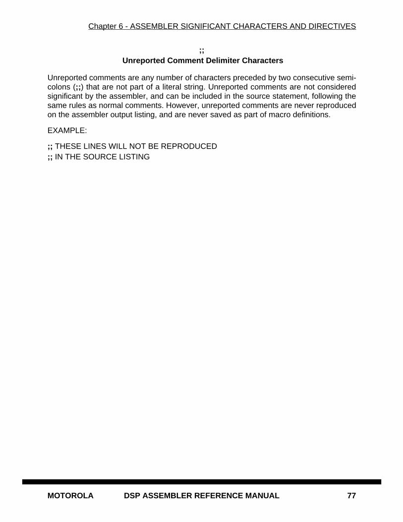
Chapter 6 - ASSEMBLER SIGNIFICANT CHARACTERS AND DIRECTIVES
MOTOROLA DSP ASSEMBLER REFERENCE MANUAL 77
;; Unreported Comment Delimiter Characters
Unreported comments are any number of characters preceded by two consecutive semi-colons (;; ) that are not part of a literal string. Unreported comments are not consideredsignificant by the assembler, and can be included in the source statement, following thesame rules as normal comments. However, unreported comments are never reproducedon the assembler output listing, and are never saved as part of macro definitions.
EXAMPLE:
;; THESE LINES WILL NOT BE REPRODUCED;; IN THE SOURCE LISTING
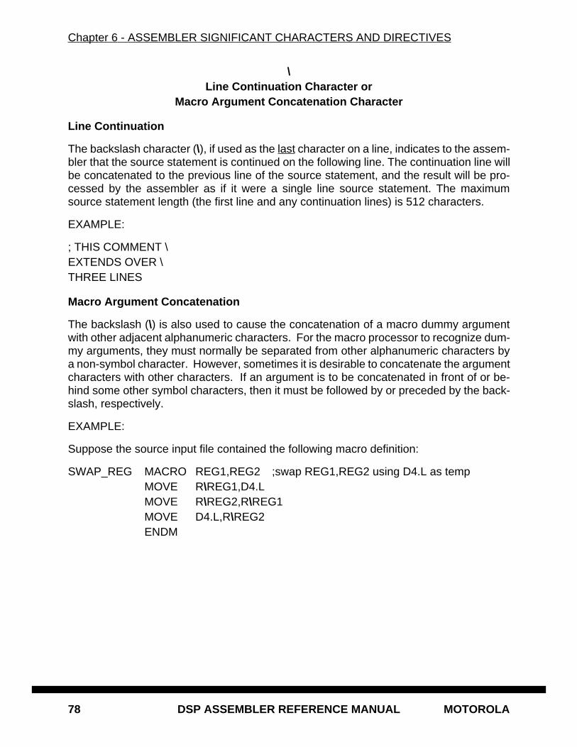
Chapter 6 - ASSEMBLER SIGNIFICANT CHARACTERS AND DIRECTIVES
78 DSP ASSEMBLER REFERENCE MANUAL MOTOROLA
\Line Continuation Character or
Macro Argument Concatenation Character
Line Continuation
The backslash character (\), if used as the last character on a line, indicates to the assem-bler that the source statement is continued on the following line. The continuation line willbe concatenated to the previous line of the source statement, and the result will be pro-cessed by the assembler as if it were a single line source statement. The maximumsource statement length (the first line and any continuation lines) is 512 characters.
EXAMPLE:
; THIS COMMENT \EXTENDS OVER \THREE LINES
Macro Argument Concatenation
The backslash (\) is also used to cause the concatenation of a macro dummy argumentwith other adjacent alphanumeric characters. For the macro processor to recognize dum-my arguments, they must normally be separated from other alphanumeric characters bya non-symbol character. However, sometimes it is desirable to concatenate the argumentcharacters with other characters. If an argument is to be concatenated in front of or be-hind some other symbol characters, then it must be followed by or preceded by the back-slash, respectively.
EXAMPLE:
Suppose the source input file contained the following macro definition:
SWAP_REG MACRO REG1,REG2 ;swap REG1,REG2 using D4.L as tempMOVE R\REG1,D4.LMOVE R\REG2,R\REG1MOVE D4.L,R\REG2ENDM
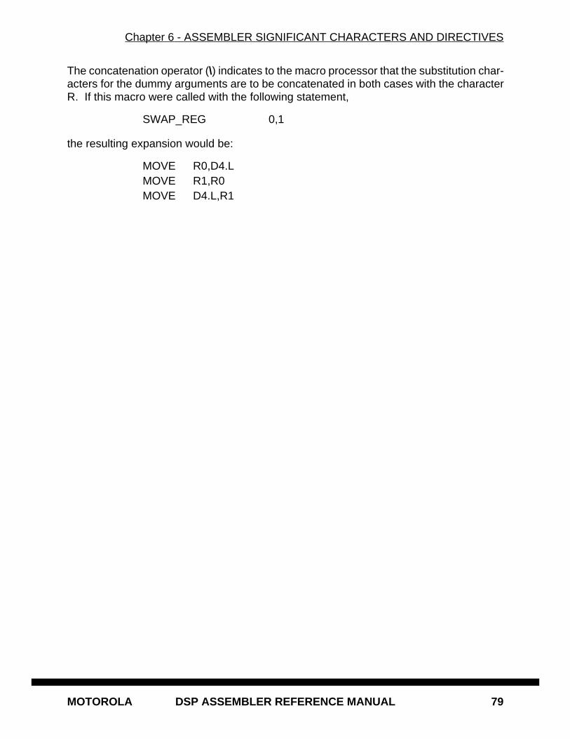
Chapter 6 - ASSEMBLER SIGNIFICANT CHARACTERS AND DIRECTIVES
MOTOROLA DSP ASSEMBLER REFERENCE MANUAL 79
The concatenation operator (\) indicates to the macro processor that the substitution char-acters for the dummy arguments are to be concatenated in both cases with the characterR. If this macro were called with the following statement,
SWAP_REG 0,1
the resulting expansion would be:
MOVE R0,D4.LMOVE R1,R0MOVE D4.L,R1
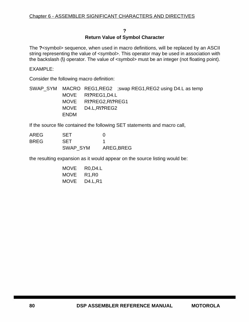
Chapter 6 - ASSEMBLER SIGNIFICANT CHARACTERS AND DIRECTIVES
80 DSP ASSEMBLER REFERENCE MANUAL MOTOROLA
?Return Value of Symbol Character
The ?<symbol> sequence, when used in macro definitions, will be replaced by an ASCIIstring representing the value of <symbol>. This operator may be used in association withthe backslash (\) operator. The value of <symbol> must be an integer (not floating point).
EXAMPLE:
Consider the following macro definition:
SWAP_SYM MACRO REG1,REG2 ;swap REG1,REG2 using D4.L as tempMOVE R\?REG1,D4.LMOVE R\?REG2,R\?REG1
MOVE D4.L,R\?REG2ENDM
If the source file contained the following SET statements and macro call,
AREG SET 0BREG SET 1
SWAP_SYM AREG,BREG
the resulting expansion as it would appear on the source listing would be:
MOVE R0,D4.LMOVE R1,R0MOVE D4.L,R1
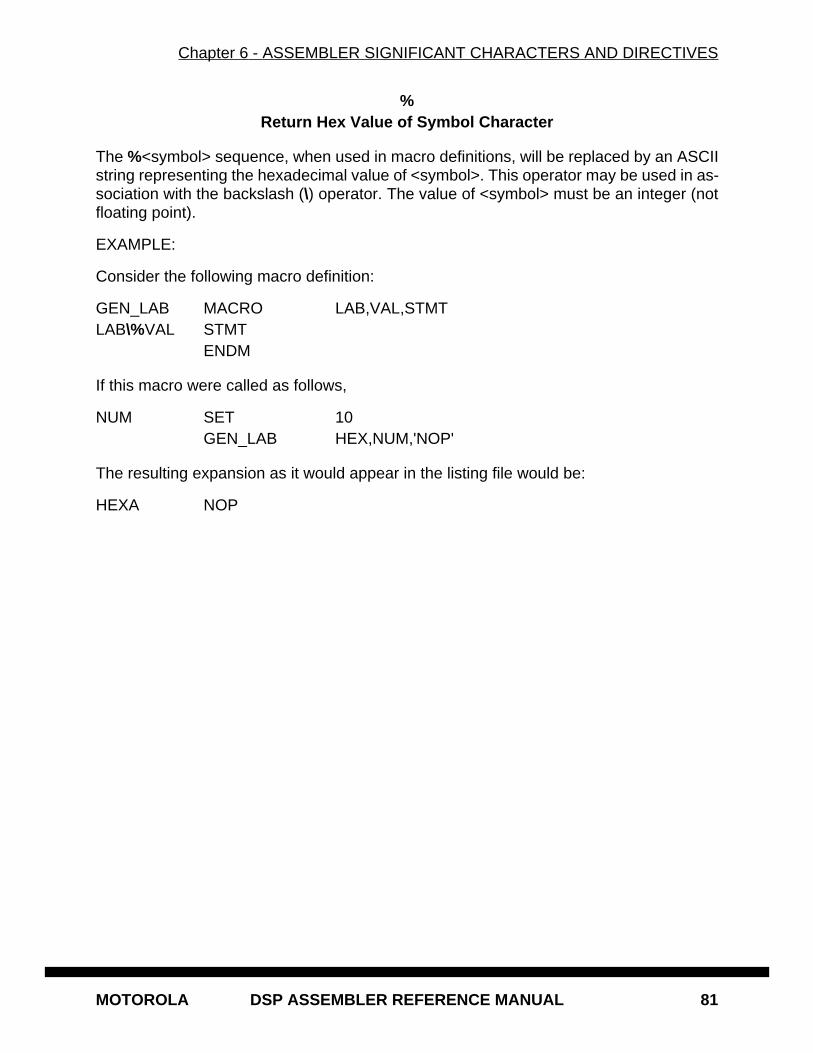
Chapter 6 - ASSEMBLER SIGNIFICANT CHARACTERS AND DIRECTIVES
MOTOROLA DSP ASSEMBLER REFERENCE MANUAL 81
%Return Hex Value of Symbol Character
The %<symbol> sequence, when used in macro definitions, will be replaced by an ASCIIstring representing the hexadecimal value of <symbol>. This operator may be used in as-sociation with the backslash (\) operator. The value of <symbol> must be an integer (notfloating point).
EXAMPLE:
Consider the following macro definition:
GEN_LAB MACRO LAB,VAL,STMTLAB\%VAL STMT
ENDM
If this macro were called as follows,
NUM SET 10GEN_LAB HEX,NUM,'NOP'
The resulting expansion as it would appear in the listing file would be:
HEXA NOP
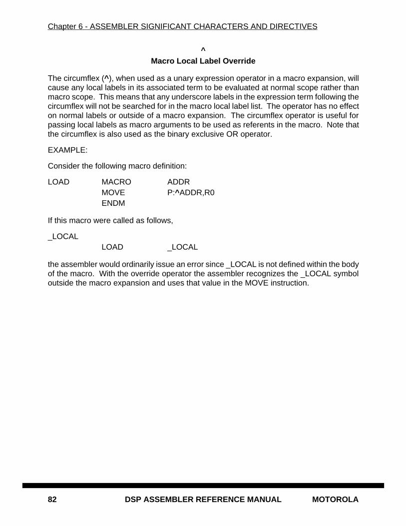
Chapter 6 - ASSEMBLER SIGNIFICANT CHARACTERS AND DIRECTIVES
82 DSP ASSEMBLER REFERENCE MANUAL MOTOROLA
^Macro Local Label Override
The circumflex (^ ), when used as a unary expression operator in a macro expansion, willcause any local labels in its associated term to be evaluated at normal scope rather thanmacro scope. This means that any underscore labels in the expression term following thecircumflex will not be searched for in the macro local label list. The operator has no effecton normal labels or outside of a macro expansion. The circumflex operator is useful forpassing local labels as macro arguments to be used as referents in the macro. Note thatthe circumflex is also used as the binary exclusive OR operator.
EXAMPLE:
Consider the following macro definition:
LOAD MACRO ADDRMOVE P:^ADDR,R0ENDM
If this macro were called as follows,
_LOCALLOAD _LOCAL
the assembler would ordinarily issue an error since _LOCAL is not defined within the bodyof the macro. With the override operator the assembler recognizes the _LOCAL symboloutside the macro expansion and uses that value in the MOVE instruction.
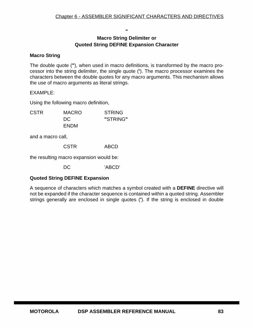
Chapter 6 - ASSEMBLER SIGNIFICANT CHARACTERS AND DIRECTIVES
MOTOROLA DSP ASSEMBLER REFERENCE MANUAL 83
"Macro String Delimiter or
Quoted String DEFINE Expansion Character
Macro String
The double quote (" ), when used in macro definitions, is transformed by the macro pro-cessor into the string delimiter, the single quote ('). The macro processor examines thecharacters between the double quotes for any macro arguments. This mechanism allowsthe use of macro arguments as literal strings.
EXAMPLE:
Using the following macro definition,
CSTR MACRO STRINGDC "STRING"ENDM
and a macro call,
CSTR ABCD
the resulting macro expansion would be:
DC 'ABCD'
Quoted String DEFINE Expansion
A sequence of characters which matches a symbol created with a DEFINE directive willnot be expanded if the character sequence is contained within a quoted string. Assemblerstrings generally are enclosed in single quotes ('). If the string is enclosed in double
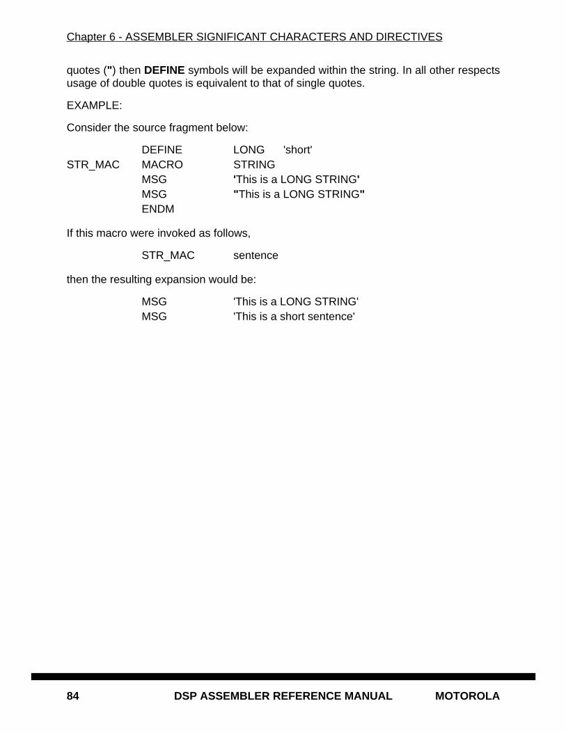
Chapter 6 - ASSEMBLER SIGNIFICANT CHARACTERS AND DIRECTIVES
84 DSP ASSEMBLER REFERENCE MANUAL MOTOROLA
quotes (" ) then DEFINE symbols will be expanded within the string. In all other respectsusage of double quotes is equivalent to that of single quotes.
EXAMPLE:
Consider the source fragment below:
DEFINE LONG 'short'STR_MAC MACRO STRING
MSG 'This is a LONG STRING'MSG "This is a LONG STRING"ENDM
If this macro were invoked as follows,
STR_MAC sentence
then the resulting expansion would be:
MSG 'This is a LONG STRING'MSG 'This is a short sentence'
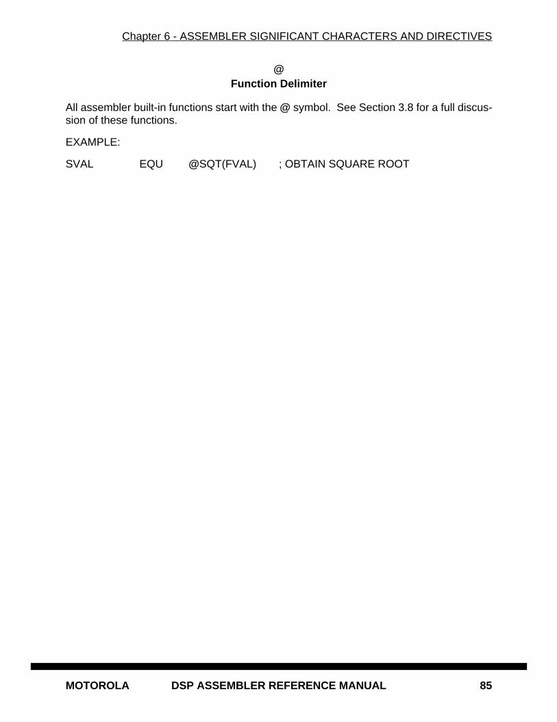
Chapter 6 - ASSEMBLER SIGNIFICANT CHARACTERS AND DIRECTIVES
MOTOROLA DSP ASSEMBLER REFERENCE MANUAL 85
@Function Delimiter
All assembler built-in functions start with the @ symbol. See Section 3.8 for a full discus-sion of these functions.
EXAMPLE:
SVAL EQU @SQT(FVAL) ; OBTAIN SQUARE ROOT
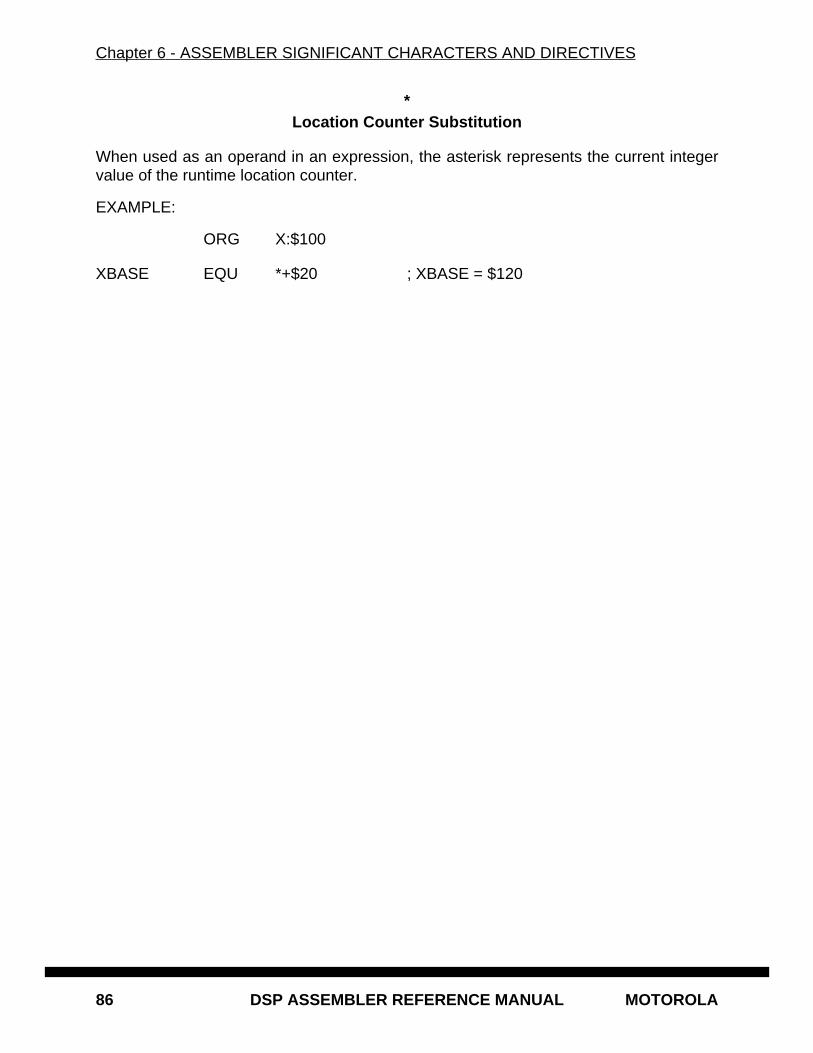
Chapter 6 - ASSEMBLER SIGNIFICANT CHARACTERS AND DIRECTIVES
86 DSP ASSEMBLER REFERENCE MANUAL MOTOROLA
*Location Counter Substitution
When used as an operand in an expression, the asterisk represents the current integervalue of the runtime location counter.
EXAMPLE:
ORG X:$100
XBASE EQU *+$20 ; XBASE = $120
Chapter 6 - ASSEMBLER SIGNIFICANT CHARACTERS AND DIRECTIVES
MOTOROLA DSP ASSEMBLER REFERENCE MANUAL 87
++String Concatenation Operator
Any two strings can be concatenated with the string concatenation operator (++). The twostrings must each be enclosed by single or double quotes, and there must be no interven-ing blanks between the string concatenation operator and the two strings.
EXAMPLE:
'ABC'++'DEF' = 'ABCDEF'
Chapter 6 - ASSEMBLER SIGNIFICANT CHARACTERS AND DIRECTIVES
88 DSP ASSEMBLER REFERENCE MANUAL MOTOROLA
[ ]Substring Delimiter
[<string>,<offset><length>]
Square brackets delimit a substring operation. The <string> argument is the sourcestring. <offset> is the substring starting position within <string>. <length> is the length ofthe desired substring. <string> may be any legal string combination, including anothersubstring. An error is issued if either <offset> or <length> exceed the length of <string>.
EXAMPLE:
DEFINE ID ['DSP56000',3,5] ; ID = '56000'
Chapter 6 - ASSEMBLER SIGNIFICANT CHARACTERS AND DIRECTIVES
MOTOROLA DSP ASSEMBLER REFERENCE MANUAL 89
<<I/O Short Addressing Mode Force Operator
Many DSP instructions allow an I/O short form of addressing. If the value of an absoluteaddress is known to the assembler on pass one, then the assembler will always pick theshortest form of addressing consistent with the instruction format. If the absolute addressis not known to the assembler on pass one (that is, the address is a forward or externalreference), then the assembler will pick the long form of addressing by default. If this isnot desired, then the I/O short form of addressing can be forced by preceding the absoluteaddress by the I/O short addressing mode force operator (<<).
EXAMPLE:
Since the symbol IOPORT is a forward reference in the following sequence of sourcelines, the assembler would pick the long absolute form of addressing by default:
BTST #4,Y:IOPORTIOPORT EQU Y:$FFF3
Because the long absolute addressing mode would cause the instruction to be two wordslong instead of one word for the I/O short absolute addressing mode, it would be desirableto force the I/O short absolute addressing mode as shown below:
BTST #4,Y:<<IOPORTIOPORT EQU Y:$FFF3
Chapter 6 - ASSEMBLER SIGNIFICANT CHARACTERS AND DIRECTIVES
90 DSP ASSEMBLER REFERENCE MANUAL MOTOROLA
<Short Addressing Mode Force Operator
Many DSP instructions allow a short form of addressing. If the value of an absolute ad-dress is known to the assembler on pass one, or the FORCE SHORT directive is active,then the assembler will always pick the shortest form of addressing consistent with theinstruction format. If the absolute address is not known to the assembler on pass one(that is, the address is a forward or external reference), then the assembler will pick thelong form of addressing by default. If this is not desired, then the short absolute form ofaddressing can be forced by preceding the absolute address by the short addressingmode force operator (<).
See also: FORCE
EXAMPLE:
Since the symbol DATAST is a forward reference in the following sequence of sourcelines, the assembler would pick the long absolute form of addressing by default:
MOVE D0.L,Y:DATASTDATAST EQU Y:$23
Because the long absolute addressing mode would cause the instruction to be two wordslong instead of one word for the short absolute addressing mode, it would be desirableto force the short absolute addressing mode as shown below:
MOVE D0.L,Y:<DATASTDATAST EQU Y:$23
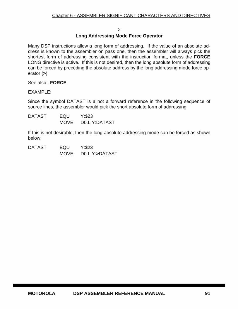
Chapter 6 - ASSEMBLER SIGNIFICANT CHARACTERS AND DIRECTIVES
MOTOROLA DSP ASSEMBLER REFERENCE MANUAL 91
>Long Addressing Mode Force Operator
Many DSP instructions allow a long form of addressing. If the value of an absolute ad-dress is known to the assembler on pass one, then the assembler will always pick theshortest form of addressing consistent with the instruction format, unless the FORCELONG directive is active. If this is not desired, then the long absolute form of addressingcan be forced by preceding the absolute address by the long addressing mode force op-erator (>).
See also: FORCE
EXAMPLE:
Since the symbol DATAST is a not a forward reference in the following sequence ofsource lines, the assembler would pick the short absolute form of addressing:
DATAST EQU Y:$23MOVE D0.L,Y:DATAST
If this is not desirable, then the long absolute addressing mode can be forced as shownbelow:
DATAST EQU Y:$23MOVE D0.L,Y:>DATAST
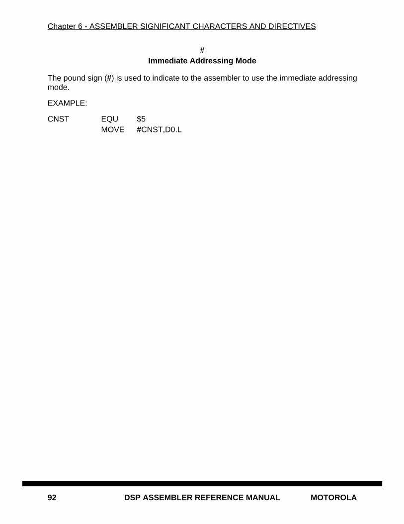
Chapter 6 - ASSEMBLER SIGNIFICANT CHARACTERS AND DIRECTIVES
92 DSP ASSEMBLER REFERENCE MANUAL MOTOROLA
#Immediate Addressing Mode
The pound sign (#) is used to indicate to the assembler to use the immediate addressingmode.
EXAMPLE:
CNST EQU $5MOVE #CNST,D0.L
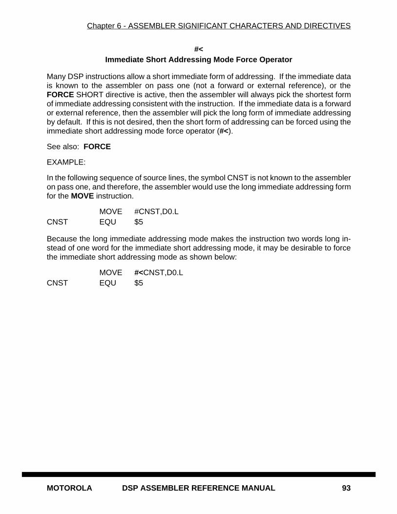
Chapter 6 - ASSEMBLER SIGNIFICANT CHARACTERS AND DIRECTIVES
MOTOROLA DSP ASSEMBLER REFERENCE MANUAL 93
#<Immediate Short Addressing Mode Force Operator
Many DSP instructions allow a short immediate form of addressing. If the immediate datais known to the assembler on pass one (not a forward or external reference), or theFORCE SHORT directive is active, then the assembler will always pick the shortest formof immediate addressing consistent with the instruction. If the immediate data is a forwardor external reference, then the assembler will pick the long form of immediate addressingby default. If this is not desired, then the short form of addressing can be forced using theimmediate short addressing mode force operator (#<).
See also: FORCE
EXAMPLE:
In the following sequence of source lines, the symbol CNST is not known to the assembleron pass one, and therefore, the assembler would use the long immediate addressing formfor the MOVE instruction.
MOVE #CNST,D0.LCNST EQU $5
Because the long immediate addressing mode makes the instruction two words long in-stead of one word for the immediate short addressing mode, it may be desirable to forcethe immediate short addressing mode as shown below:
MOVE #<CNST,D0.LCNST EQU $5
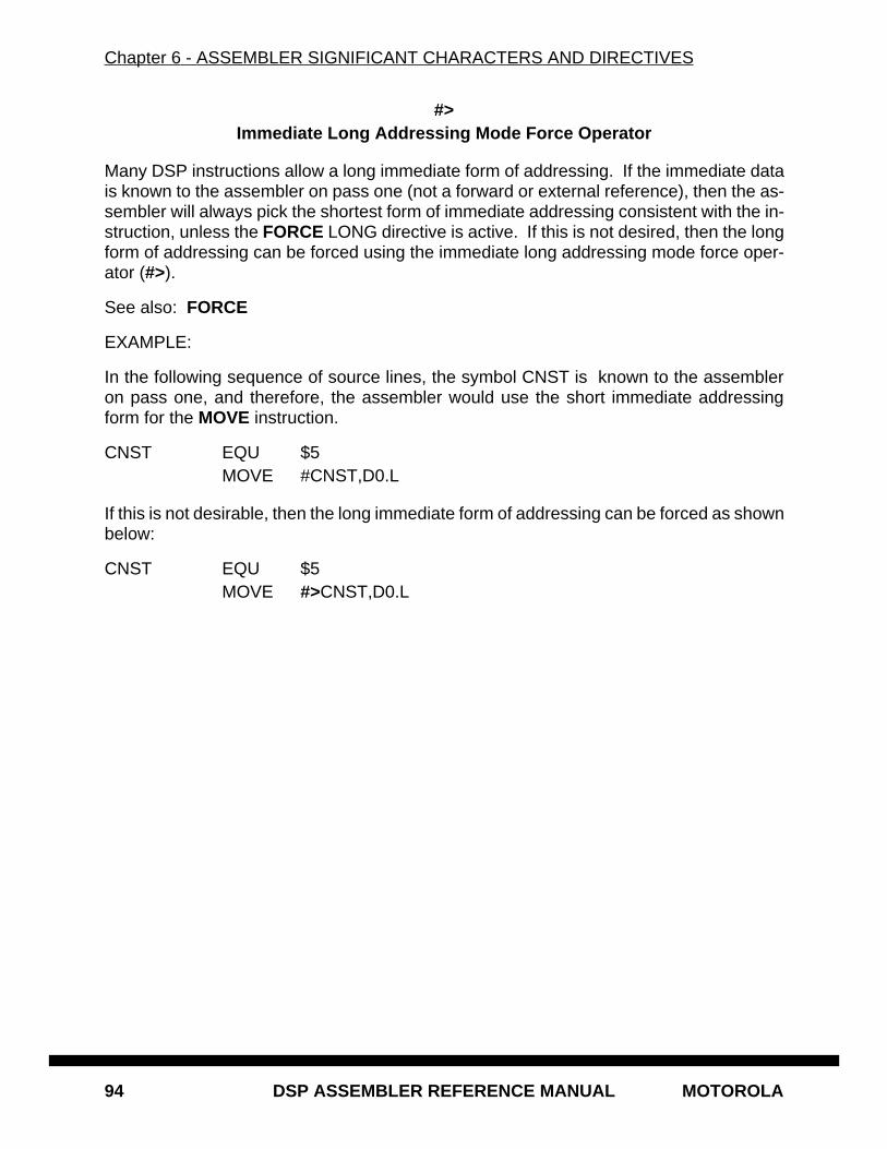
Chapter 6 - ASSEMBLER SIGNIFICANT CHARACTERS AND DIRECTIVES
94 DSP ASSEMBLER REFERENCE MANUAL MOTOROLA
#>Immediate Long Addressing Mode Force Operator
Many DSP instructions allow a long immediate form of addressing. If the immediate datais known to the assembler on pass one (not a forward or external reference), then the as-sembler will always pick the shortest form of immediate addressing consistent with the in-struction, unless the FORCE LONG directive is active. If this is not desired, then the longform of addressing can be forced using the immediate long addressing mode force oper-ator (#>).
See also: FORCE
EXAMPLE:
In the following sequence of source lines, the symbol CNST is known to the assembleron pass one, and therefore, the assembler would use the short immediate addressingform for the MOVE instruction.
CNST EQU $5MOVE #CNST,D0.L
If this is not desirable, then the long immediate form of addressing can be forced as shownbelow:
CNST EQU $5MOVE #>CNST,D0.L
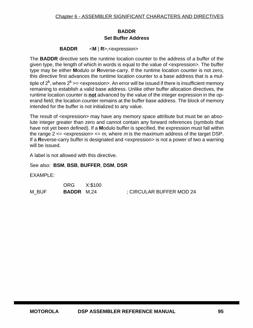
Chapter 6 - ASSEMBLER SIGNIFICANT CHARACTERS AND DIRECTIVES
MOTOROLA DSP ASSEMBLER REFERENCE MANUAL 95
BADDRSet Buffer Address
BADDR <M | R>,<expression>
The BADDR directive sets the runtime location counter to the address of a buffer of thegiven type, the length of which in words is equal to the value of <expression>. The buffertype may be either Modulo or Reverse-carry. If the runtime location counter is not zero,this directive first advances the runtime location counter to a base address that is a mul-tiple of 2k, where 2k >= <expression>. An error will be issued if there is insufficient memoryremaining to establish a valid base address. Unlike other buffer allocation directives, theruntime location counter is not advanced by the value of the integer expression in the op-erand field; the location counter remains at the buffer base address. The block of memoryintended for the buffer is not initialized to any value.
The result of <expression> may have any memory space attribute but must be an abso-lute integer greater than zero and cannot contain any forward references (symbols thathave not yet been defined). If a Modulo buffer is specified, the expression must fall withinthe range 2 <= <expression> <= m, where m is the maximum address of the target DSP.If a Reverse-carry buffer is designated and <expression> is not a power of two a warningwill be issued.
A label is not allowed with this directive.
See also: BSM, BSB , BUFFER, DSM, DSR
EXAMPLE:
ORG X:$100M_BUF BADDR M,24 ; CIRCULAR BUFFER MOD 24
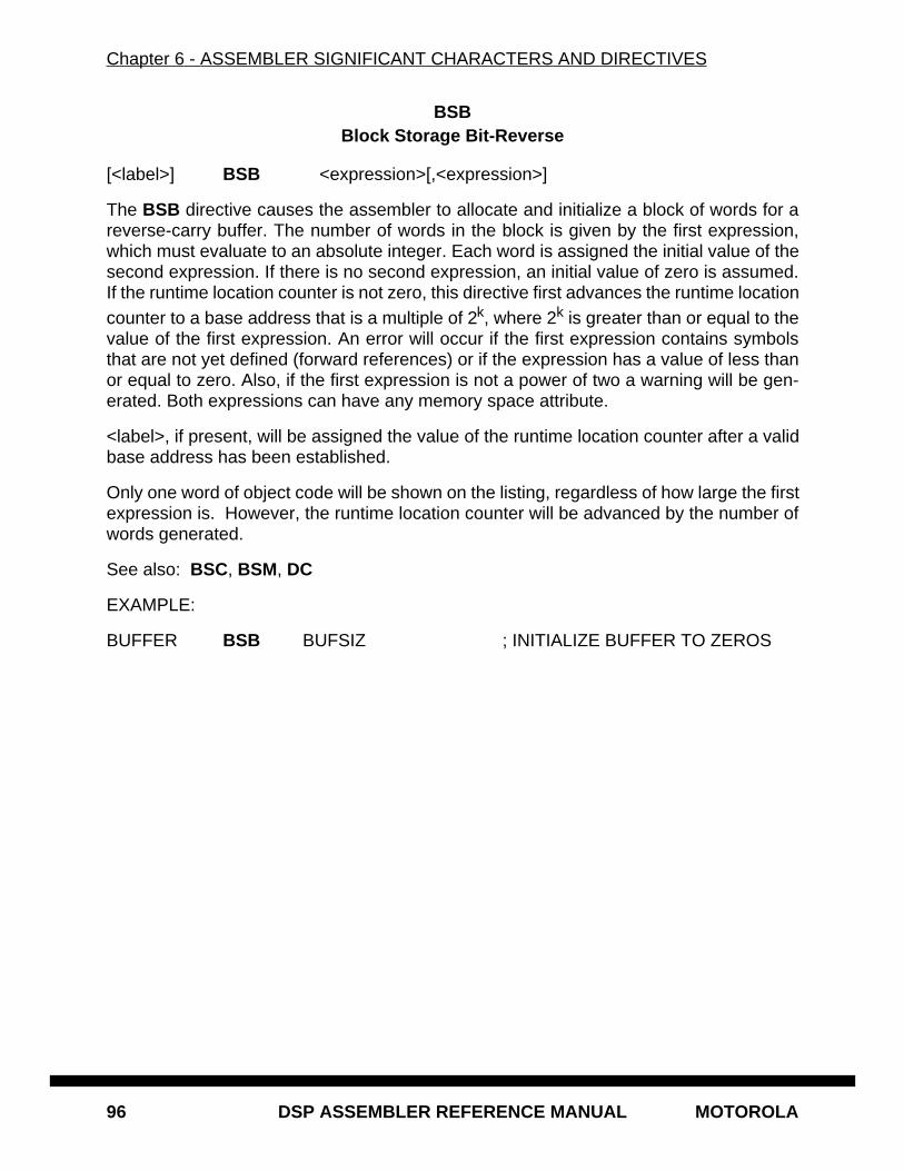
Chapter 6 - ASSEMBLER SIGNIFICANT CHARACTERS AND DIRECTIVES
96 DSP ASSEMBLER REFERENCE MANUAL MOTOROLA
BSBBlock Storage Bit-Reverse
[<label>] BSB <expression>[,<expression>]
The BSB directive causes the assembler to allocate and initialize a block of words for areverse-carry buffer. The number of words in the block is given by the first expression,which must evaluate to an absolute integer. Each word is assigned the initial value of thesecond expression. If there is no second expression, an initial value of zero is assumed.If the runtime location counter is not zero, this directive first advances the runtime locationcounter to a base address that is a multiple of 2k, where 2k is greater than or equal to thevalue of the first expression. An error will occur if the first expression contains symbolsthat are not yet defined (forward references) or if the expression has a value of less thanor equal to zero. Also, if the first expression is not a power of two a warning will be gen-erated. Both expressions can have any memory space attribute.
<label>, if present, will be assigned the value of the runtime location counter after a validbase address has been established.
Only one word of object code will be shown on the listing, regardless of how large the firstexpression is. However, the runtime location counter will be advanced by the number ofwords generated.
See also: BSC, BSM, DC
EXAMPLE:
BUFFER BSB BUFSIZ ; INITIALIZE BUFFER TO ZEROS
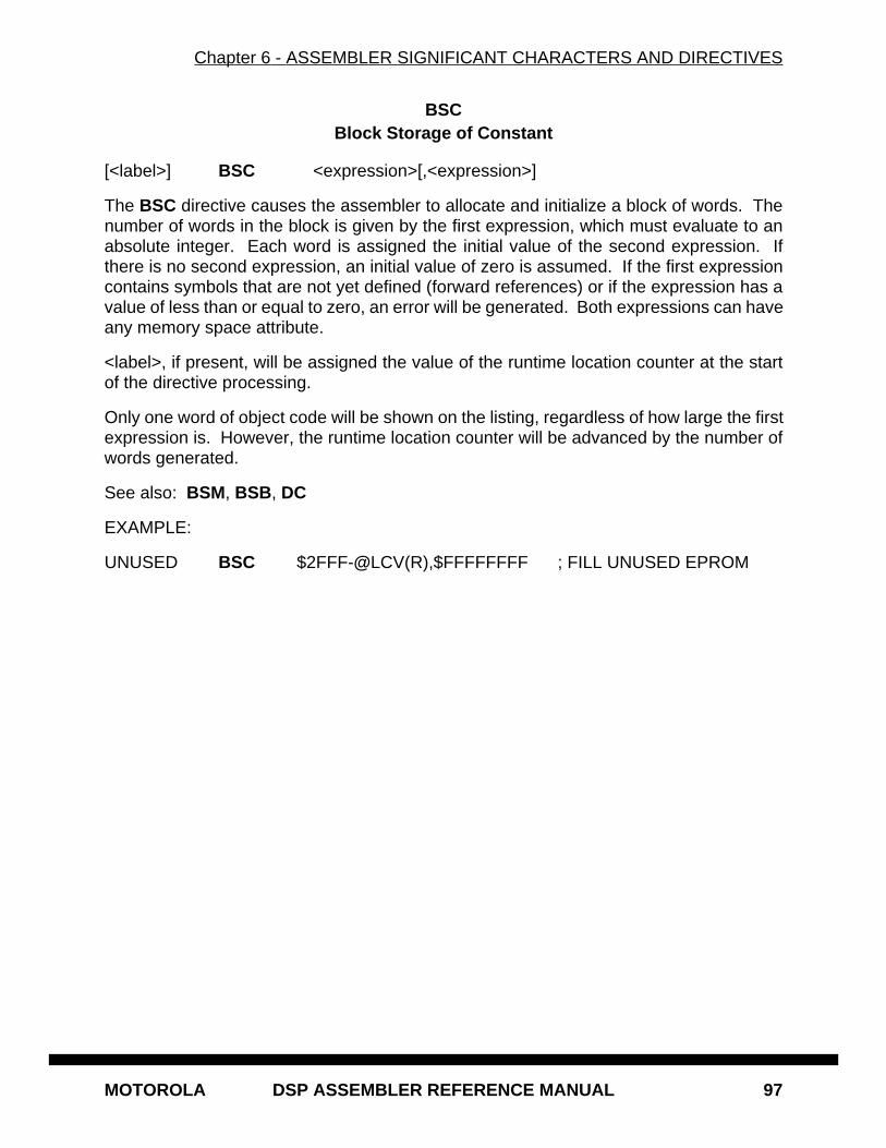
Chapter 6 - ASSEMBLER SIGNIFICANT CHARACTERS AND DIRECTIVES
MOTOROLA DSP ASSEMBLER REFERENCE MANUAL 97
BSCBlock Storage of Constant
[<label>] BSC <expression>[,<expression>]
The BSC directive causes the assembler to allocate and initialize a block of words. Thenumber of words in the block is given by the first expression, which must evaluate to anabsolute integer. Each word is assigned the initial value of the second expression. Ifthere is no second expression, an initial value of zero is assumed. If the first expressioncontains symbols that are not yet defined (forward references) or if the expression has avalue of less than or equal to zero, an error will be generated. Both expressions can haveany memory space attribute.
<label>, if present, will be assigned the value of the runtime location counter at the startof the directive processing.
Only one word of object code will be shown on the listing, regardless of how large the firstexpression is. However, the runtime location counter will be advanced by the number ofwords generated.
See also: BSM, BSB , DC
EXAMPLE:
UNUSED BSC $2FFF-@LCV(R),$FFFFFFFF ; FILL UNUSED EPROM
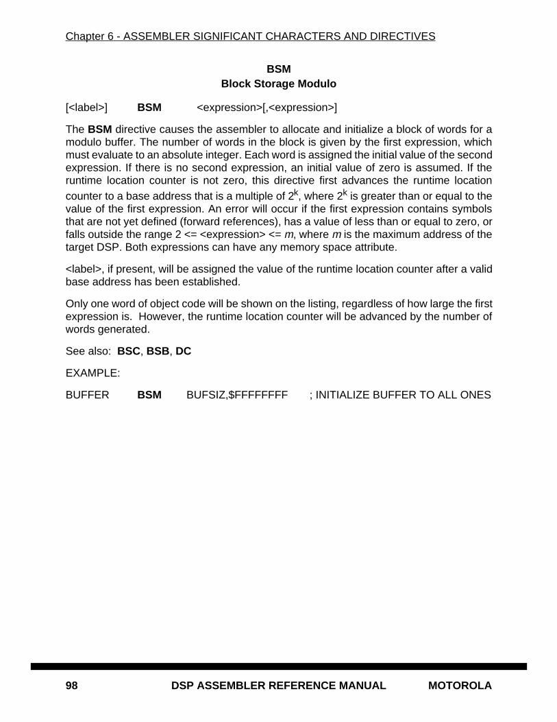
Chapter 6 - ASSEMBLER SIGNIFICANT CHARACTERS AND DIRECTIVES
98 DSP ASSEMBLER REFERENCE MANUAL MOTOROLA
BSMBlock Storage Modulo
[<label>] BSM <expression>[,<expression>]
The BSM directive causes the assembler to allocate and initialize a block of words for amodulo buffer. The number of words in the block is given by the first expression, whichmust evaluate to an absolute integer. Each word is assigned the initial value of the secondexpression. If there is no second expression, an initial value of zero is assumed. If theruntime location counter is not zero, this directive first advances the runtime locationcounter to a base address that is a multiple of 2k, where 2k is greater than or equal to thevalue of the first expression. An error will occur if the first expression contains symbolsthat are not yet defined (forward references), has a value of less than or equal to zero, orfalls outside the range 2 <= <expression> <= m, where m is the maximum address of thetarget DSP. Both expressions can have any memory space attribute.
<label>, if present, will be assigned the value of the runtime location counter after a validbase address has been established.
Only one word of object code will be shown on the listing, regardless of how large the firstexpression is. However, the runtime location counter will be advanced by the number ofwords generated.
See also: BSC, BSB , DC
EXAMPLE:
BUFFER BSM BUFSIZ,$FFFFFFFF ; INITIALIZE BUFFER TO ALL ONES
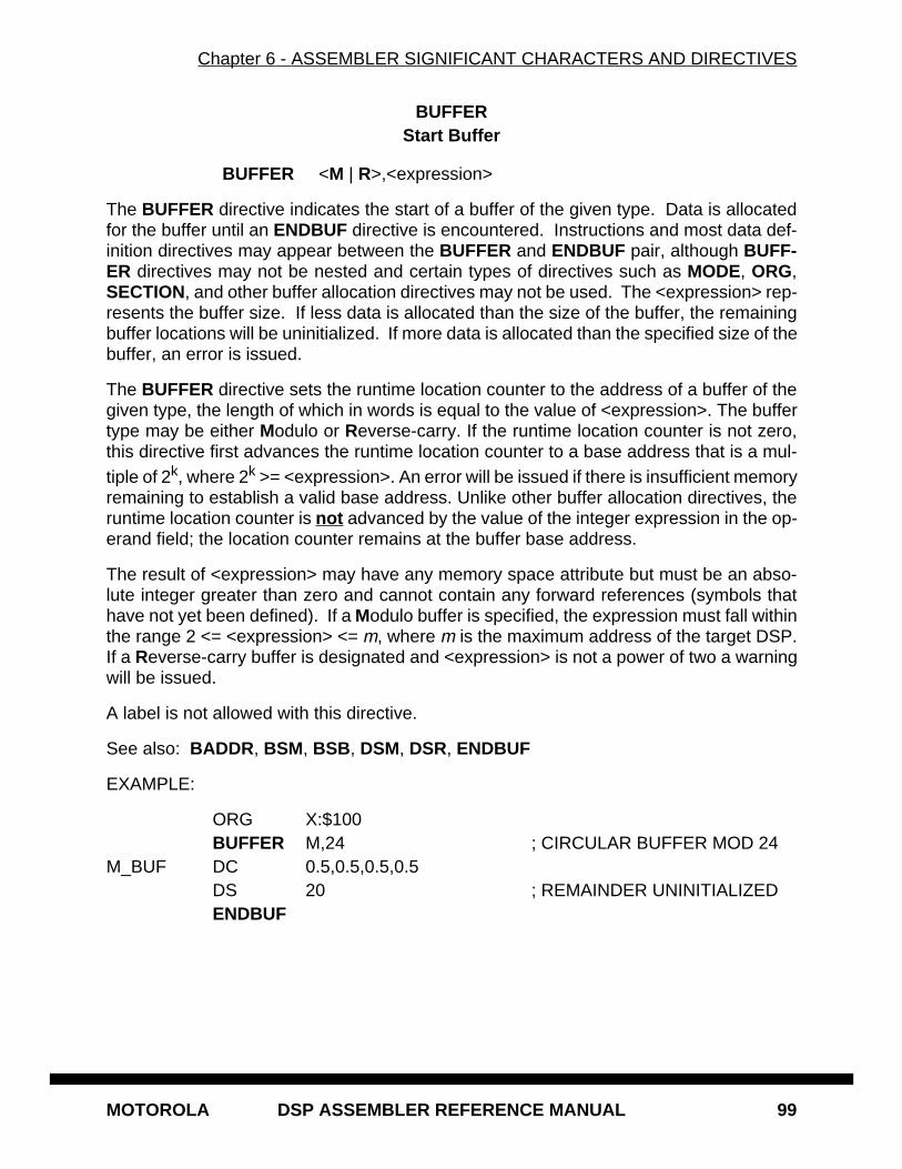
Chapter 6 - ASSEMBLER SIGNIFICANT CHARACTERS AND DIRECTIVES
MOTOROLA DSP ASSEMBLER REFERENCE MANUAL 99
BUFFERStart Buffer
BUFFER <M | R>,<expression>
The BUFFER directive indicates the start of a buffer of the given type. Data is allocatedfor the buffer until an ENDBUF directive is encountered. Instructions and most data def-inition directives may appear between the BUFFER and ENDBUF pair, although BUFF-ER directives may not be nested and certain types of directives such as MODE, ORG,SECTION, and other buffer allocation directives may not be used. The <expression> rep-resents the buffer size. If less data is allocated than the size of the buffer, the remainingbuffer locations will be uninitialized. If more data is allocated than the specified size of thebuffer, an error is issued.
The BUFFER directive sets the runtime location counter to the address of a buffer of thegiven type, the length of which in words is equal to the value of <expression>. The buffertype may be either Modulo or Reverse-carry. If the runtime location counter is not zero,this directive first advances the runtime location counter to a base address that is a mul-tiple of 2k, where 2k >= <expression>. An error will be issued if there is insufficient memoryremaining to establish a valid base address. Unlike other buffer allocation directives, theruntime location counter is not advanced by the value of the integer expression in the op-erand field; the location counter remains at the buffer base address.
The result of <expression> may have any memory space attribute but must be an abso-lute integer greater than zero and cannot contain any forward references (symbols thathave not yet been defined). If a Modulo buffer is specified, the expression must fall withinthe range 2 <= <expression> <= m, where m is the maximum address of the target DSP.If a Reverse-carry buffer is designated and <expression> is not a power of two a warningwill be issued.
A label is not allowed with this directive.
See also: BADDR , BSM, BSB , DSM, DSR, ENDBUF
EXAMPLE:
ORG X:$100BUFFER M,24 ; CIRCULAR BUFFER MOD 24
M_BUF DC 0.5,0.5,0.5,0.5DS 20 ; REMAINDER UNINITIALIZEDENDBUF
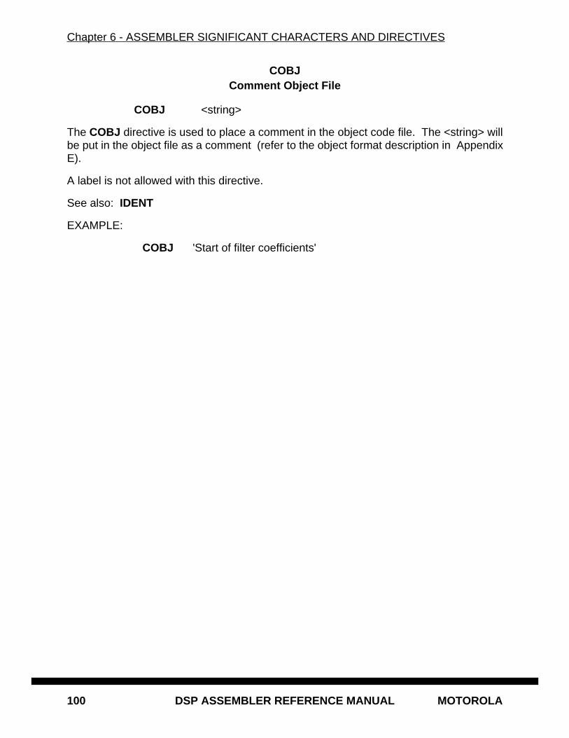
Chapter 6 - ASSEMBLER SIGNIFICANT CHARACTERS AND DIRECTIVES
100 DSP ASSEMBLER REFERENCE MANUAL MOTOROLA
COBJComment Object File
COBJ <string>
The COBJ directive is used to place a comment in the object code file. The <string> willbe put in the object file as a comment (refer to the object format description in AppendixE).
A label is not allowed with this directive.
See also: IDENT
EXAMPLE:
COBJ 'Start of filter coefficients'
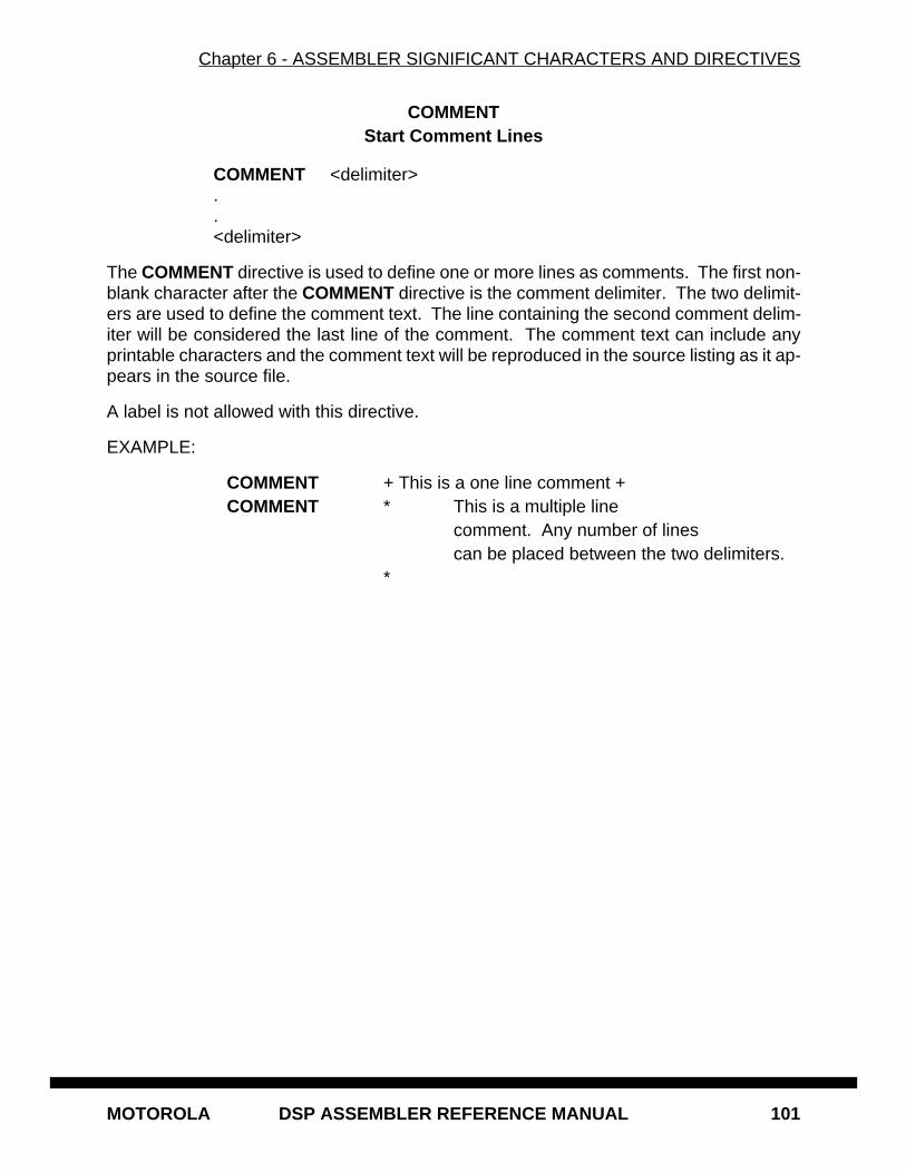
Chapter 6 - ASSEMBLER SIGNIFICANT CHARACTERS AND DIRECTIVES
MOTOROLA DSP ASSEMBLER REFERENCE MANUAL 101
COMMENTStart Comment Lines
COMMENT <delimiter>..<delimiter>
The COMMENT directive is used to define one or more lines as comments. The first non-blank character after the COMMENT directive is the comment delimiter. The two delimit-ers are used to define the comment text. The line containing the second comment delim-iter will be considered the last line of the comment. The comment text can include anyprintable characters and the comment text will be reproduced in the source listing as it ap-pears in the source file.
A label is not allowed with this directive.
EXAMPLE:
COMMENT + This is a one line comment +COMMENT * This is a multiple line
comment. Any number of linescan be placed between the two delimiters.
*
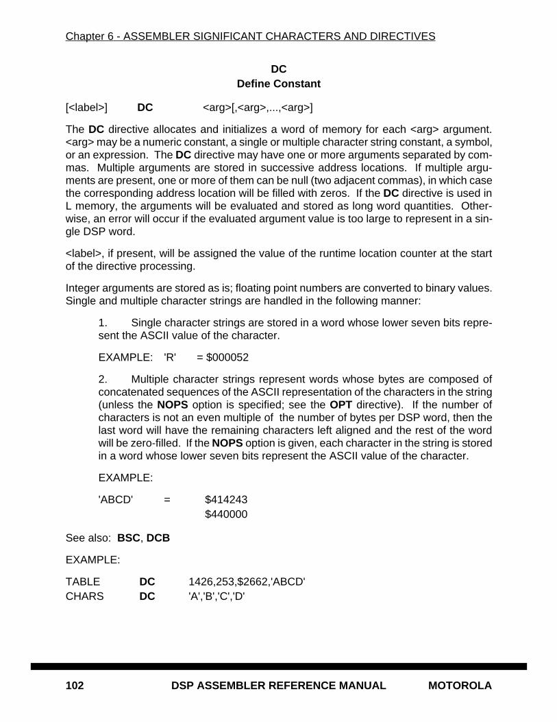
Chapter 6 - ASSEMBLER SIGNIFICANT CHARACTERS AND DIRECTIVES
102 DSP ASSEMBLER REFERENCE MANUAL MOTOROLA
DCDefine Constant
[<label>] DC <arg>[,<arg>,...,<arg>]
The DC directive allocates and initializes a word of memory for each <arg> argument.<arg> may be a numeric constant, a single or multiple character string constant, a symbol,or an expression. The DC directive may have one or more arguments separated by com-mas. Multiple arguments are stored in successive address locations. If multiple argu-ments are present, one or more of them can be null (two adjacent commas), in which casethe corresponding address location will be filled with zeros. If the DC directive is used inL memory, the arguments will be evaluated and stored as long word quantities. Other-wise, an error will occur if the evaluated argument value is too large to represent in a sin-gle DSP word.
<label>, if present, will be assigned the value of the runtime location counter at the startof the directive processing.
Integer arguments are stored as is; floating point numbers are converted to binary values.Single and multiple character strings are handled in the following manner:
1. Single character strings are stored in a word whose lower seven bits repre-sent the ASCII value of the character.
EXAMPLE: 'R' = $000052
2. Multiple character strings represent words whose bytes are composed ofconcatenated sequences of the ASCII representation of the characters in the string(unless the NOPS option is specified; see the OPT directive). If the number ofcharacters is not an even multiple of the number of bytes per DSP word, then thelast word will have the remaining characters left aligned and the rest of the wordwill be zero-filled. If the NOPS option is given, each character in the string is storedin a word whose lower seven bits represent the ASCII value of the character.
EXAMPLE:
'ABCD' = $414243$440000
See also: BSC, DCB
EXAMPLE:
TABLE DC 1426,253,$2662,'ABCD'CHARS DC 'A','B','C','D'
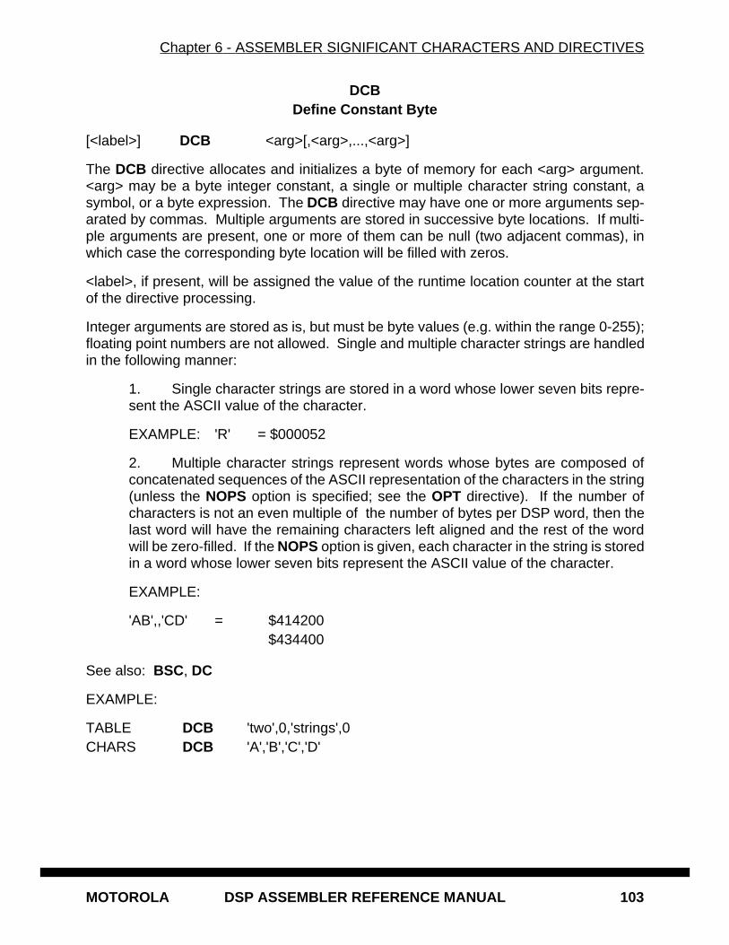
Chapter 6 - ASSEMBLER SIGNIFICANT CHARACTERS AND DIRECTIVES
MOTOROLA DSP ASSEMBLER REFERENCE MANUAL 103
DCBDefine Constant Byte
[<label>] DCB <arg>[,<arg>,...,<arg>]
The DCB directive allocates and initializes a byte of memory for each <arg> argument.<arg> may be a byte integer constant, a single or multiple character string constant, asymbol, or a byte expression. The DCB directive may have one or more arguments sep-arated by commas. Multiple arguments are stored in successive byte locations. If multi-ple arguments are present, one or more of them can be null (two adjacent commas), inwhich case the corresponding byte location will be filled with zeros.
<label>, if present, will be assigned the value of the runtime location counter at the startof the directive processing.
Integer arguments are stored as is, but must be byte values (e.g. within the range 0-255);floating point numbers are not allowed. Single and multiple character strings are handledin the following manner:
1. Single character strings are stored in a word whose lower seven bits repre-sent the ASCII value of the character.
EXAMPLE: 'R' = $000052
2. Multiple character strings represent words whose bytes are composed ofconcatenated sequences of the ASCII representation of the characters in the string(unless the NOPS option is specified; see the OPT directive). If the number ofcharacters is not an even multiple of the number of bytes per DSP word, then thelast word will have the remaining characters left aligned and the rest of the wordwill be zero-filled. If the NOPS option is given, each character in the string is storedin a word whose lower seven bits represent the ASCII value of the character.
EXAMPLE:
'AB',,'CD' = $414200$434400
See also: BSC, DC
EXAMPLE:
TABLE DCB 'two',0,'strings',0CHARS DCB 'A','B','C','D'
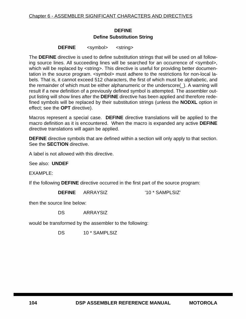
Chapter 6 - ASSEMBLER SIGNIFICANT CHARACTERS AND DIRECTIVES
104 DSP ASSEMBLER REFERENCE MANUAL MOTOROLA
DEFINEDefine Substitution String
DEFINE <symbol> <string>
The DEFINE directive is used to define substitution strings that will be used on all follow-ing source lines. All succeeding lines will be searched for an occurrence of <symbol>,which will be replaced by <string>. This directive is useful for providing better documen-tation in the source program. <symbol> must adhere to the restrictions for non-local la-bels. That is, it cannot exceed 512 characters, the first of which must be alphabetic, andthe remainder of which must be either alphanumeric or the underscore(_). A warning willresult if a new definition of a previously defined symbol is attempted. The assembler out-put listing will show lines after the DEFINE directive has been applied and therefore rede-fined symbols will be replaced by their substitution strings (unless the NODXL option ineffect; see the OPT directive).
Macros represent a special case. DEFINE directive translations will be applied to themacro definition as it is encountered. When the macro is expanded any active DEFINEdirective translations will again be applied.
DEFINE directive symbols that are defined within a section will only apply to that section.See the SECTION directive.
A label is not allowed with this directive.
See also: UNDEF
EXAMPLE:
If the following DEFINE directive occurred in the first part of the source program:
DEFINE ARRAYSIZ '10 * SAMPLSIZ'
then the source line below:
DS ARRAYSIZ
would be transformed by the assembler to the following:
DS 10 * SAMPLSIZ
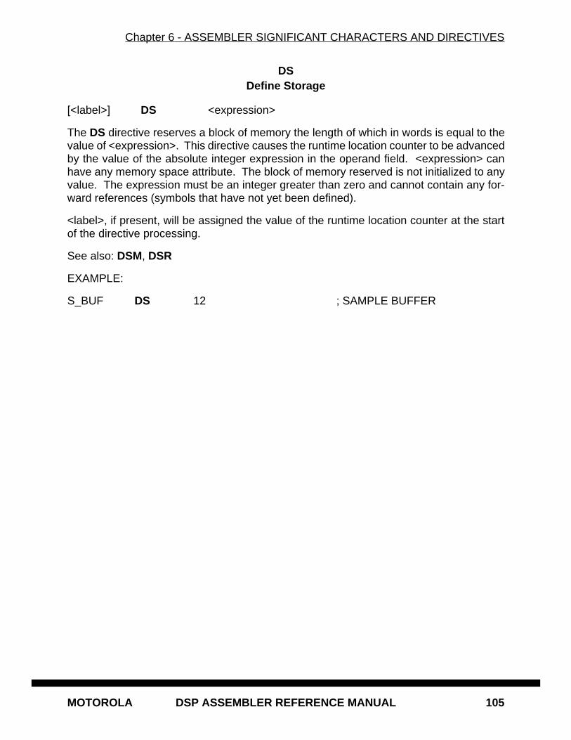
Chapter 6 - ASSEMBLER SIGNIFICANT CHARACTERS AND DIRECTIVES
MOTOROLA DSP ASSEMBLER REFERENCE MANUAL 105
DSDefine Storage
[<label>] DS <expression>
The DS directive reserves a block of memory the length of which in words is equal to thevalue of <expression>. This directive causes the runtime location counter to be advancedby the value of the absolute integer expression in the operand field. <expression> canhave any memory space attribute. The block of memory reserved is not initialized to anyvalue. The expression must be an integer greater than zero and cannot contain any for-ward references (symbols that have not yet been defined).
<label>, if present, will be assigned the value of the runtime location counter at the startof the directive processing.
See also: DSM, DSR
EXAMPLE:
S_BUF DS 12 ; SAMPLE BUFFER
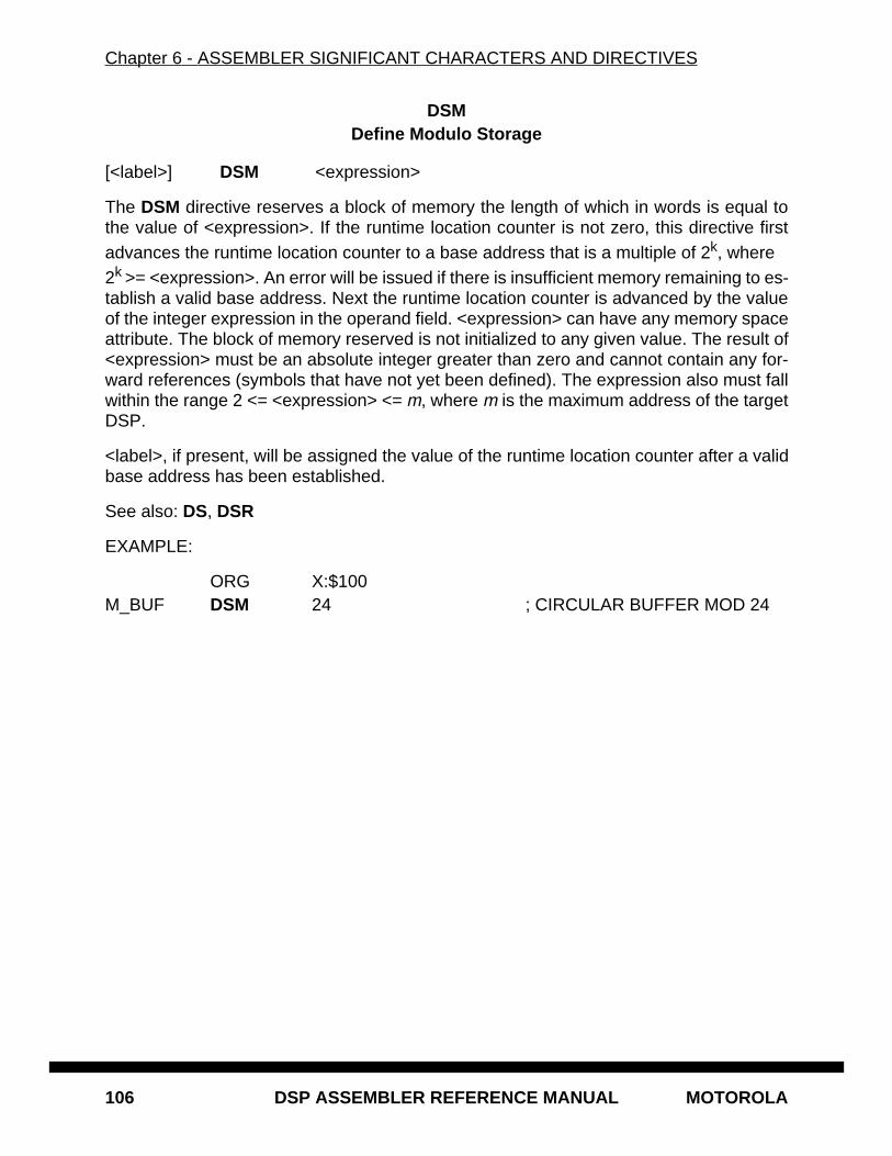
Chapter 6 - ASSEMBLER SIGNIFICANT CHARACTERS AND DIRECTIVES
106 DSP ASSEMBLER REFERENCE MANUAL MOTOROLA
DSMDefine Modulo Storage
[<label>] DSM <expression>
The DSM directive reserves a block of memory the length of which in words is equal tothe value of <expression>. If the runtime location counter is not zero, this directive firstadvances the runtime location counter to a base address that is a multiple of 2k, where 2k >= <expression>. An error will be issued if there is insufficient memory remaining to es-tablish a valid base address. Next the runtime location counter is advanced by the valueof the integer expression in the operand field. <expression> can have any memory spaceattribute. The block of memory reserved is not initialized to any given value. The result of<expression> must be an absolute integer greater than zero and cannot contain any for-ward references (symbols that have not yet been defined). The expression also must fallwithin the range 2 <= <expression> <= m, where m is the maximum address of the targetDSP.
<label>, if present, will be assigned the value of the runtime location counter after a validbase address has been established.
See also: DS, DSR
EXAMPLE:
ORG X:$100M_BUF DSM 24 ; CIRCULAR BUFFER MOD 24

Chapter 6 - ASSEMBLER SIGNIFICANT CHARACTERS AND DIRECTIVES
MOTOROLA DSP ASSEMBLER REFERENCE MANUAL 107
DSRDefine Reverse Carry Storage
[<label>] DSR <expression>
The DSR directive reserves a block of memory the length of which in words is equal to thevalue of <expression>. If the runtime location counter is not zero, this directive first ad-vances the runtime location counter to a base address that is a multiple of 2k, where 2k >= <expression>. An error will be issued if there is insufficient memory remaining toestablish a valid base address. Next the runtime location counter is advanced by the valueof the integer expression in the operand field. <expression> can have any memory spaceattribute. The block of memory reserved is not initialized to any given value. The result of<expression> must be an absolute integer greater than zero and cannot contain any for-ward references (symbols that have not yet been defined). Since the DSR directive is use-ful mainly for generating FFT buffers, if <expression> is not a power of two a warning willbe generated.
<label>, if present, will be assigned the value of the runtime location counter after a validbase address has been established.
See also: DS, DSM
EXAMPLE:
ORG X:$100R_BUF DSR 8 ; REVERSE CARRY BUFFER FOR 16 POINT FFT
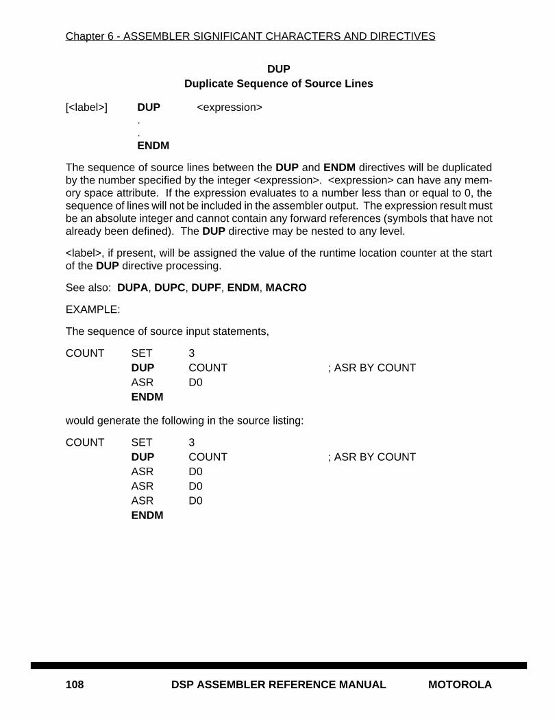
Chapter 6 - ASSEMBLER SIGNIFICANT CHARACTERS AND DIRECTIVES
108 DSP ASSEMBLER REFERENCE MANUAL MOTOROLA
DUPDuplicate Sequence of Source Lines
[<label>] DUP <expression> . . ENDM
The sequence of source lines between the DUP and ENDM directives will be duplicatedby the number specified by the integer <expression>. <expression> can have any mem-ory space attribute. If the expression evaluates to a number less than or equal to 0, thesequence of lines will not be included in the assembler output. The expression result mustbe an absolute integer and cannot contain any forward references (symbols that have notalready been defined). The DUP directive may be nested to any level.
<label>, if present, will be assigned the value of the runtime location counter at the startof the DUP directive processing.
See also: DUPA, DUPC, DUPF, ENDM, MACRO
EXAMPLE:
The sequence of source input statements,
COUNT SET 3DUP COUNT ; ASR BY COUNTASR D0ENDM
would generate the following in the source listing:
COUNT SET 3DUP COUNT ; ASR BY COUNTASR D0ASR D0ASR D0ENDM
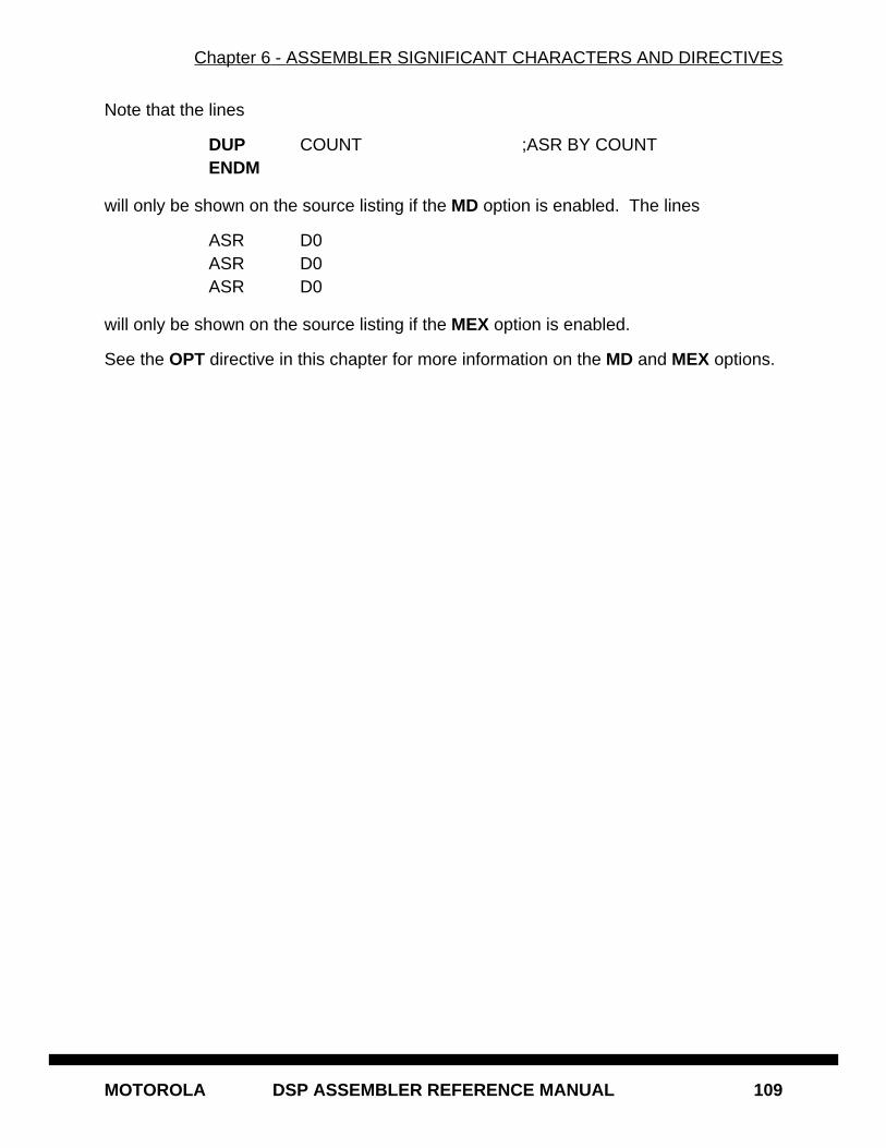
Chapter 6 - ASSEMBLER SIGNIFICANT CHARACTERS AND DIRECTIVES
MOTOROLA DSP ASSEMBLER REFERENCE MANUAL 109
Note that the lines
DUP COUNT ;ASR BY COUNTENDM
will only be shown on the source listing if the MD option is enabled. The lines
ASR D0ASR D0ASR D0
will only be shown on the source listing if the MEX option is enabled.
See the OPT directive in this chapter for more information on the MD and MEX options.
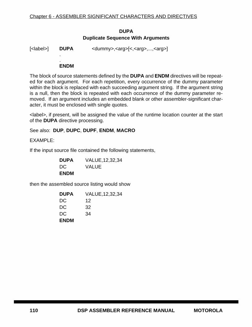
Chapter 6 - ASSEMBLER SIGNIFICANT CHARACTERS AND DIRECTIVES
110 DSP ASSEMBLER REFERENCE MANUAL MOTOROLA
DUPADuplicate Sequence With Arguments
[<label>] DUPA <dummy>,<arg>[<,<arg>,...,<arg>]..ENDM
The block of source statements defined by the DUPA and ENDM directives will be repeat-ed for each argument. For each repetition, every occurrence of the dummy parameterwithin the block is replaced with each succeeding argument string. If the argument stringis a null, then the block is repeated with each occurrence of the dummy parameter re-moved. If an argument includes an embedded blank or other assembler-significant char-acter, it must be enclosed with single quotes.
<label>, if present, will be assigned the value of the runtime location counter at the startof the DUPA directive processing.
See also: DUP, DUPC, DUPF, ENDM, MACRO
EXAMPLE:
If the input source file contained the following statements,
DUPA VALUE,12,32,34DC VALUEENDM
then the assembled source listing would show
DUPA VALUE,12,32,34DC 12DC 32DC 34ENDM
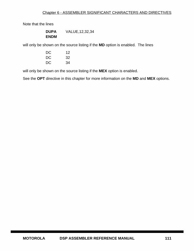
Chapter 6 - ASSEMBLER SIGNIFICANT CHARACTERS AND DIRECTIVES
MOTOROLA DSP ASSEMBLER REFERENCE MANUAL 111
Note that the lines
DUPA VALUE,12,32,34ENDM
will only be shown on the source listing if the MD option is enabled. The lines
DC 12DC 32DC 34
will only be shown on the source listing if the MEX option is enabled.
See the OPT directive in this chapter for more information on the MD and MEX options.
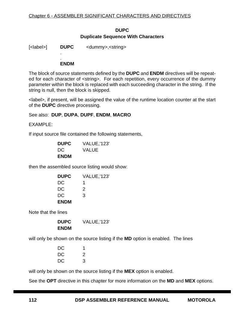
Chapter 6 - ASSEMBLER SIGNIFICANT CHARACTERS AND DIRECTIVES
112 DSP ASSEMBLER REFERENCE MANUAL MOTOROLA
DUPCDuplicate Sequence With Characters
[<label>] DUPC <dummy>,<string> . . ENDM
The block of source statements defined by the DUPC and ENDM directives will be repeat-ed for each character of <string>. For each repetition, every occurrence of the dummyparameter within the block is replaced with each succeeding character in the string. If thestring is null, then the block is skipped.
<label>, if present, will be assigned the value of the runtime location counter at the startof the DUPC directive processing.
See also: DUP, DUPA, DUPF, ENDM, MACRO
EXAMPLE:
If input source file contained the following statements,
DUPC VALUE,'123'DC VALUEENDM
then the assembled source listing would show:
DUPC VALUE,'123'DC 1DC 2DC 3ENDM
Note that the lines
DUPC VALUE,'123'ENDM
will only be shown on the source listing if the MD option is enabled. The lines
DC 1DC 2DC 3
will only be shown on the source listing if the MEX option is enabled.
See the OPT directive in this chapter for more information on the MD and MEX options.
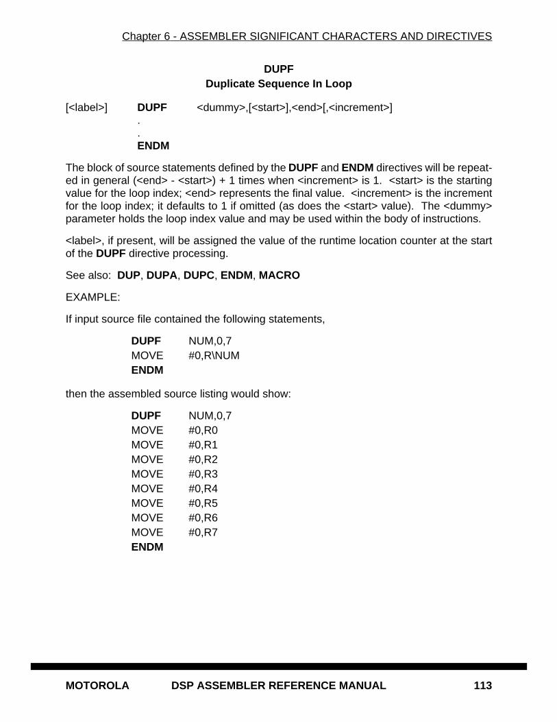
Chapter 6 - ASSEMBLER SIGNIFICANT CHARACTERS AND DIRECTIVES
MOTOROLA DSP ASSEMBLER REFERENCE MANUAL 113
DUPFDuplicate Sequence In Loop
[<label>] DUPF <dummy>,[<start>],<end>[,<increment>] . . ENDM
The block of source statements defined by the DUPF and ENDM directives will be repeat-ed in general (<end> - <start>) + 1 times when <increment> is 1. <start> is the startingvalue for the loop index; <end> represents the final value. <increment> is the incrementfor the loop index; it defaults to 1 if omitted (as does the <start> value). The <dummy>parameter holds the loop index value and may be used within the body of instructions.
<label>, if present, will be assigned the value of the runtime location counter at the startof the DUPF directive processing.
See also: DUP, DUPA, DUPC, ENDM, MACRO
EXAMPLE:
If input source file contained the following statements,
DUPF NUM,0,7MOVE #0,R\NUMENDM
then the assembled source listing would show:
DUPF NUM,0,7MOVE #0,R0MOVE #0,R1MOVE #0,R2MOVE #0,R3MOVE #0,R4MOVE #0,R5MOVE #0,R6MOVE #0,R7ENDM
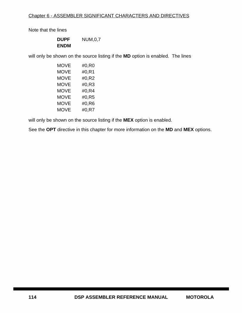
Chapter 6 - ASSEMBLER SIGNIFICANT CHARACTERS AND DIRECTIVES
114 DSP ASSEMBLER REFERENCE MANUAL MOTOROLA
Note that the lines
DUPF NUM,0,7ENDM
will only be shown on the source listing if the MD option is enabled. The lines
MOVE #0,R0MOVE #0,R1MOVE #0,R2MOVE #0,R3MOVE #0,R4MOVE #0,R5MOVE #0,R6MOVE #0,R7
will only be shown on the source listing if the MEX option is enabled.
See the OPT directive in this chapter for more information on the MD and MEX options.
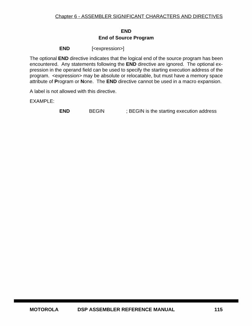
Chapter 6 - ASSEMBLER SIGNIFICANT CHARACTERS AND DIRECTIVES
MOTOROLA DSP ASSEMBLER REFERENCE MANUAL 115
ENDEnd of Source Program
END [<expression>]
The optional END directive indicates that the logical end of the source program has beenencountered. Any statements following the END directive are ignored. The optional ex-pression in the operand field can be used to specify the starting execution address of theprogram. <expression> may be absolute or relocatable, but must have a memory spaceattribute of Program or None. The END directive cannot be used in a macro expansion.
A label is not allowed with this directive.
EXAMPLE:
END BEGIN ; BEGIN is the starting execution address
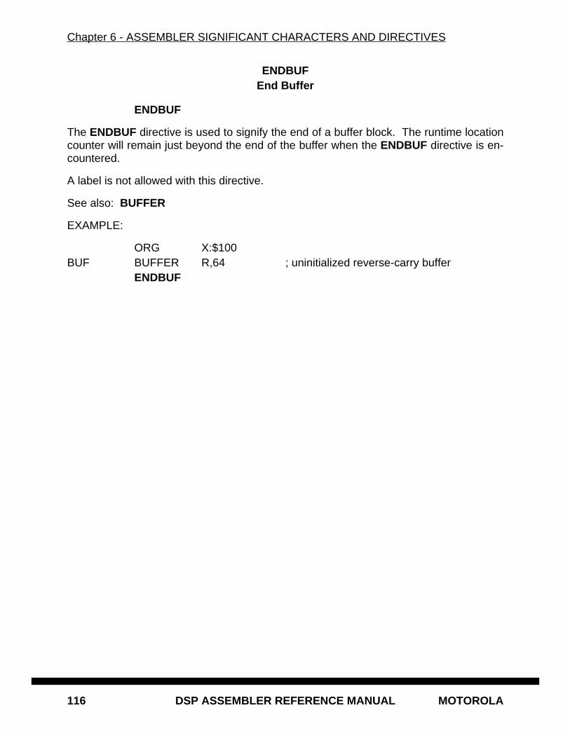
Chapter 6 - ASSEMBLER SIGNIFICANT CHARACTERS AND DIRECTIVES
116 DSP ASSEMBLER REFERENCE MANUAL MOTOROLA
ENDBUFEnd Buffer
ENDBUF
The ENDBUF directive is used to signify the end of a buffer block. The runtime locationcounter will remain just beyond the end of the buffer when the ENDBUF directive is en-countered.
A label is not allowed with this directive.
See also: BUFFER
EXAMPLE:
ORG X:$100BUF BUFFER R,64 ; uninitialized reverse-carry buffer
ENDBUF
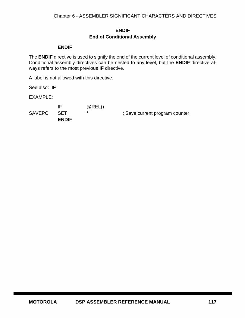
Chapter 6 - ASSEMBLER SIGNIFICANT CHARACTERS AND DIRECTIVES
MOTOROLA DSP ASSEMBLER REFERENCE MANUAL 117
ENDIFEnd of Conditional Assembly
ENDIF
The ENDIF directive is used to signify the end of the current level of conditional assembly.Conditional assembly directives can be nested to any level, but the ENDIF directive al-ways refers to the most previous IF directive.
A label is not allowed with this directive.
See also: IF
EXAMPLE:
IF @REL()SAVEPC SET * ; Save current program counter
ENDIF

Chapter 6 - ASSEMBLER SIGNIFICANT CHARACTERS AND DIRECTIVES
118 DSP ASSEMBLER REFERENCE MANUAL MOTOROLA
ENDMEnd of Macro Definition
ENDM
Every MACRO, DUP, DUPA, and DUPC directive must be terminated by an ENDM direc-tive.
A label is not allowed with this directive.
See also: DUP, DUPA, DUPC, MACRO
EXAMPLE:
SWAP_SYM MACRO REG1,REG ;swap REG1,REG2 using D4.L as tempMOVE R\?REG1,D4.LMOVE R\?REG2,R\?REG1
MOVE D4.L,R\?REG2ENDM
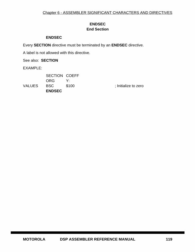
Chapter 6 - ASSEMBLER SIGNIFICANT CHARACTERS AND DIRECTIVES
MOTOROLA DSP ASSEMBLER REFERENCE MANUAL 119
ENDSECEnd Section
ENDSEC
Every SECTION directive must be terminated by an ENDSEC directive.
A label is not allowed with this directive.
See also: SECTION
EXAMPLE:
SECTION COEFFORG Y:
VALUES BSC $100 ; Initialize to zeroENDSEC
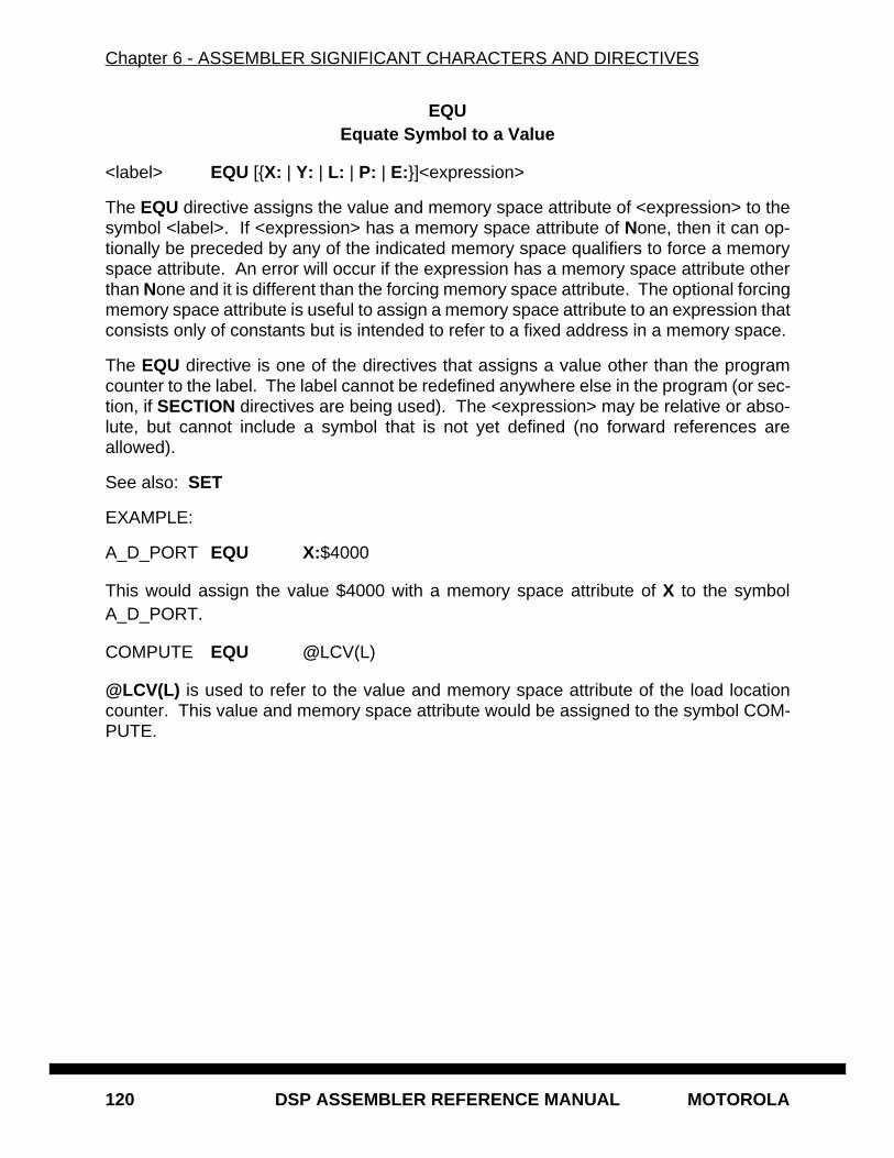
Chapter 6 - ASSEMBLER SIGNIFICANT CHARACTERS AND DIRECTIVES
120 DSP ASSEMBLER REFERENCE MANUAL MOTOROLA
EQUEquate Symbol to a Value
<label> EQU [{X: | Y: | L: | P: | E:}]<expression>
The EQU directive assigns the value and memory space attribute of <expression> to thesymbol <label>. If <expression> has a memory space attribute of None, then it can op-tionally be preceded by any of the indicated memory space qualifiers to force a memoryspace attribute. An error will occur if the expression has a memory space attribute otherthan None and it is different than the forcing memory space attribute. The optional forcingmemory space attribute is useful to assign a memory space attribute to an expression thatconsists only of constants but is intended to refer to a fixed address in a memory space.
The EQU directive is one of the directives that assigns a value other than the programcounter to the label. The label cannot be redefined anywhere else in the program (or sec-tion, if SECTION directives are being used). The <expression> may be relative or abso-lute, but cannot include a symbol that is not yet defined (no forward references areallowed).
See also: SET
EXAMPLE:
A_D_PORT EQU X:$4000
This would assign the value $4000 with a memory space attribute of X to the symbolA_D_PORT.
COMPUTE EQU @LCV(L)
@LCV(L) is used to refer to the value and memory space attribute of the load locationcounter. This value and memory space attribute would be assigned to the symbol COM-PUTE.
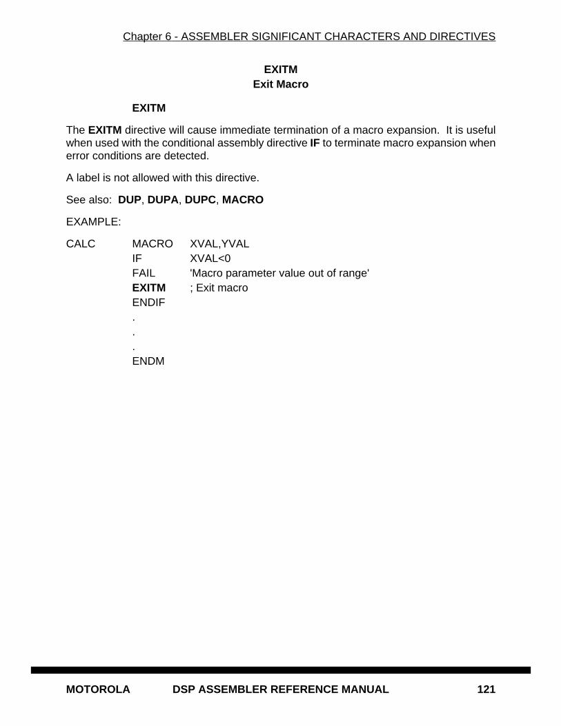
Chapter 6 - ASSEMBLER SIGNIFICANT CHARACTERS AND DIRECTIVES
MOTOROLA DSP ASSEMBLER REFERENCE MANUAL 121
EXITMExit Macro
EXITM
The EXITM directive will cause immediate termination of a macro expansion. It is usefulwhen used with the conditional assembly directive IF to terminate macro expansion whenerror conditions are detected.
A label is not allowed with this directive.
See also: DUP, DUPA, DUPC, MACRO
EXAMPLE:
CALC MACRO XVAL,YVALIF XVAL<0FAIL 'Macro parameter value out of range'EXITM ; Exit macroENDIF...ENDM
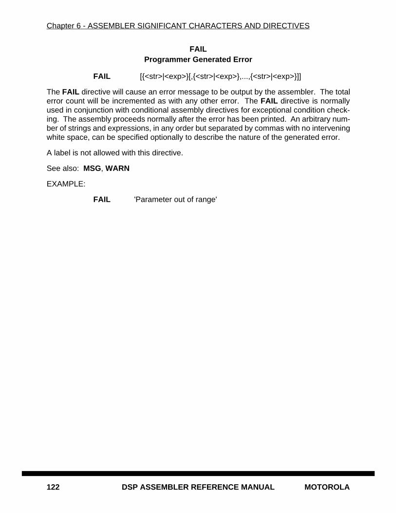
Chapter 6 - ASSEMBLER SIGNIFICANT CHARACTERS AND DIRECTIVES
122 DSP ASSEMBLER REFERENCE MANUAL MOTOROLA
FAILProgrammer Generated Error
FAIL [{<str>|<exp>}[,{<str>|<exp>},...,{<str>|<exp>}]]
The FAIL directive will cause an error message to be output by the assembler. The totalerror count will be incremented as with any other error. The FAIL directive is normallyused in conjunction with conditional assembly directives for exceptional condition check-ing. The assembly proceeds normally after the error has been printed. An arbitrary num-ber of strings and expressions, in any order but separated by commas with no interveningwhite space, can be specified optionally to describe the nature of the generated error.
A label is not allowed with this directive.
See also: MSG, WARN
EXAMPLE:
FAIL 'Parameter out of range'
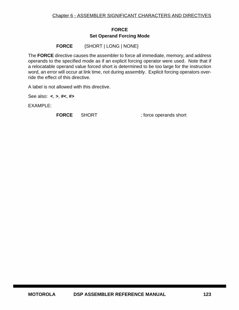
Chapter 6 - ASSEMBLER SIGNIFICANT CHARACTERS AND DIRECTIVES
MOTOROLA DSP ASSEMBLER REFERENCE MANUAL 123
FORCESet Operand Forcing Mode
FORCE {SHORT | LONG | NONE}
The FORCE directive causes the assembler to force all immediate, memory, and addressoperands to the specified mode as if an explicit forcing operator were used. Note that ifa relocatable operand value forced short is determined to be too large for the instructionword, an error will occur at link time, not during assembly. Explicit forcing operators over-ride the effect of this directive.
A label is not allowed with this directive.
See also: <, >, #<, #>
EXAMPLE:
FORCE SHORT ; force operands short
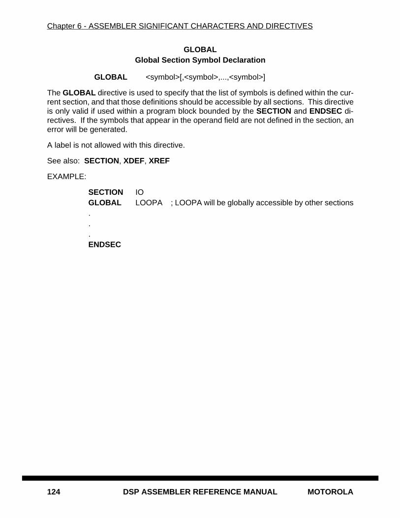
Chapter 6 - ASSEMBLER SIGNIFICANT CHARACTERS AND DIRECTIVES
124 DSP ASSEMBLER REFERENCE MANUAL MOTOROLA
GLOBALGlobal Section Symbol Declaration
GLOBAL <symbol>[,<symbol>,...,<symbol>]
The GLOBAL directive is used to specify that the list of symbols is defined within the cur-rent section, and that those definitions should be accessible by all sections. This directiveis only valid if used within a program block bounded by the SECTION and ENDSEC di-rectives. If the symbols that appear in the operand field are not defined in the section, anerror will be generated.
A label is not allowed with this directive.
See also: SECTION, XDEF, XREF
EXAMPLE:
SECTION IOGLOBAL LOOPA ; LOOPA will be globally accessible by other sections...ENDSEC
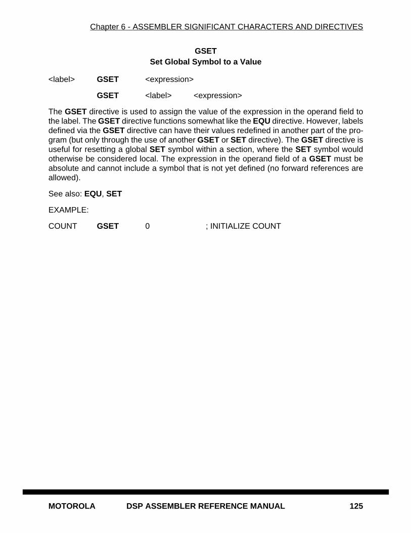
Chapter 6 - ASSEMBLER SIGNIFICANT CHARACTERS AND DIRECTIVES
MOTOROLA DSP ASSEMBLER REFERENCE MANUAL 125
GSETSet Global Symbol to a Value
<label> GSET <expression>
GSET <label> <expression>
The GSET directive is used to assign the value of the expression in the operand field tothe label. The GSET directive functions somewhat like the EQU directive. However, labelsdefined via the GSET directive can have their values redefined in another part of the pro-gram (but only through the use of another GSET or SET directive). The GSET directive isuseful for resetting a global SET symbol within a section, where the SET symbol wouldotherwise be considered local. The expression in the operand field of a GSET must beabsolute and cannot include a symbol that is not yet defined (no forward references areallowed).
See also: EQU, SET
EXAMPLE:
COUNT GSET 0 ; INITIALIZE COUNT
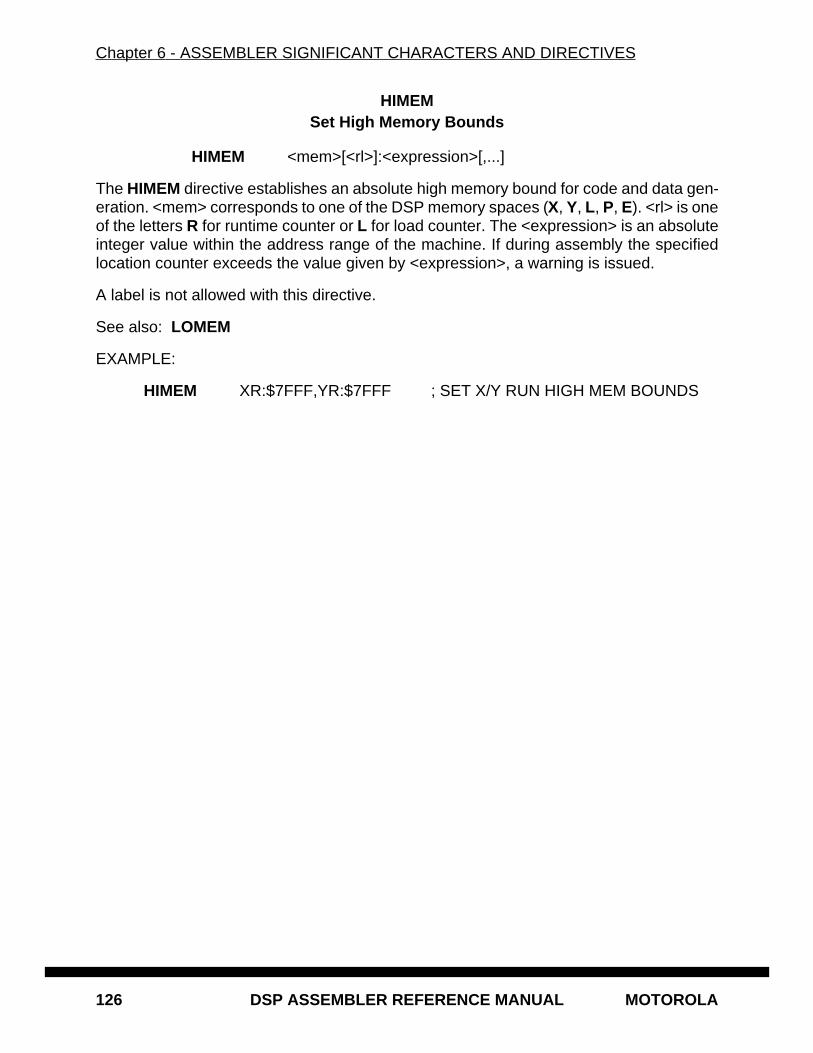
Chapter 6 - ASSEMBLER SIGNIFICANT CHARACTERS AND DIRECTIVES
126 DSP ASSEMBLER REFERENCE MANUAL MOTOROLA
HIMEMSet High Memory Bounds
HIMEM <mem>[<rl>]:<expression>[,...]
The HIMEM directive establishes an absolute high memory bound for code and data gen-eration. <mem> corresponds to one of the DSP memory spaces (X, Y, L, P, E). <rl> is oneof the letters R for runtime counter or L for load counter. The <expression> is an absoluteinteger value within the address range of the machine. If during assembly the specifiedlocation counter exceeds the value given by <expression>, a warning is issued.
A label is not allowed with this directive.
See also: LOMEM
EXAMPLE:
HIMEM XR:$7FFF,YR:$7FFF ; SET X/Y RUN HIGH MEM BOUNDS
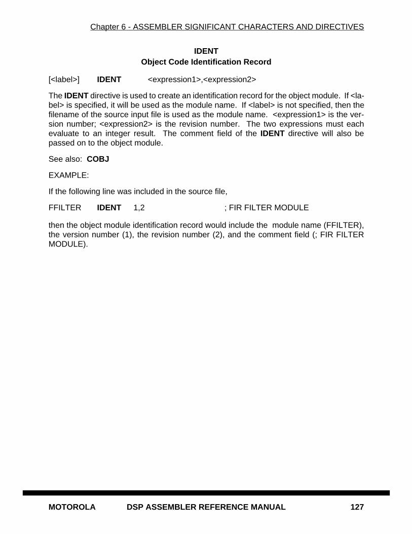
Chapter 6 - ASSEMBLER SIGNIFICANT CHARACTERS AND DIRECTIVES
MOTOROLA DSP ASSEMBLER REFERENCE MANUAL 127
IDENTObject Code Identification Record
[<label>] IDENT <expression1>,<expression2>
The IDENT directive is used to create an identification record for the object module. If <la-bel> is specified, it will be used as the module name. If <label> is not specified, then thefilename of the source input file is used as the module name. <expression1> is the ver-sion number; <expression2> is the revision number. The two expressions must eachevaluate to an integer result. The comment field of the IDENT directive will also bepassed on to the object module.
See also: COBJ
EXAMPLE:
If the following line was included in the source file,
FFILTER IDENT 1,2 ; FIR FILTER MODULE
then the object module identification record would include the module name (FFILTER),the version number (1), the revision number (2), and the comment field (; FIR FILTERMODULE).
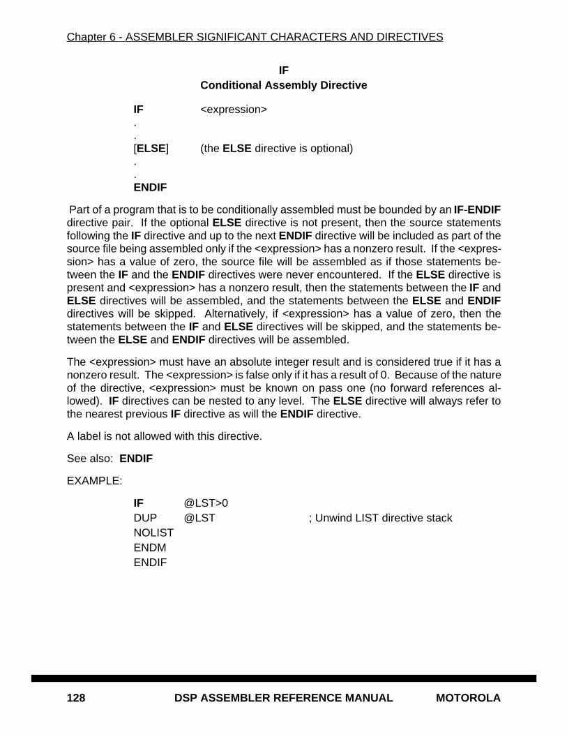
Chapter 6 - ASSEMBLER SIGNIFICANT CHARACTERS AND DIRECTIVES
128 DSP ASSEMBLER REFERENCE MANUAL MOTOROLA
IFConditional Assembly Directive
IF <expression>..[ELSE] (the ELSE directive is optional)..ENDIF
Part of a program that is to be conditionally assembled must be bounded by an IF-ENDIFdirective pair. If the optional ELSE directive is not present, then the source statementsfollowing the IF directive and up to the next ENDIF directive will be included as part of thesource file being assembled only if the <expression> has a nonzero result. If the <expres-sion> has a value of zero, the source file will be assembled as if those statements be-tween the IF and the ENDIF directives were never encountered. If the ELSE directive ispresent and <expression> has a nonzero result, then the statements between the IF andELSE directives will be assembled, and the statements between the ELSE and ENDIFdirectives will be skipped. Alternatively, if <expression> has a value of zero, then thestatements between the IF and ELSE directives will be skipped, and the statements be-tween the ELSE and ENDIF directives will be assembled.
The <expression> must have an absolute integer result and is considered true if it has anonzero result. The <expression> is false only if it has a result of 0. Because of the natureof the directive, <expression> must be known on pass one (no forward references al-lowed). IF directives can be nested to any level. The ELSE directive will always refer tothe nearest previous IF directive as will the ENDIF directive.
A label is not allowed with this directive.
See also: ENDIF
EXAMPLE:
IF @LST>0DUP @LST ; Unwind LIST directive stackNOLISTENDMENDIF

Chapter 6 - ASSEMBLER SIGNIFICANT CHARACTERS AND DIRECTIVES
MOTOROLA DSP ASSEMBLER REFERENCE MANUAL 129
INCLUDEInclude Secondary File
INCLUDE <string> | <<string>>
This directive is inserted into the source program at any point where a secondary file is tobe included in the source input stream. The string specifies the filename of the secondaryfile. The filename must be compatible with the operating system and can include a direc-tory specification. If no extension is given for the filename, a default extension of .ASM issupplied.
The file is searched for first in the current directory, unless the <<string>> syntax is used,or in the directory specified in <string>. If the file is not found, and the -I option was usedon the command line that invoked the assembler, then the string specified with the -I op-tion is prefixed to <string> and that directory is searched. If the <<string>> syntax is given,the file is searched for only in the directories specified with the -I option. Refer to Chapter1, RUNNING THE ASSEMBLER.
A label is not allowed with this directive.
See also: MACLIB
EXAMPLE:
INCLUDE 'headers/io.asm' ; Unix example
INCLUDE 'storage\mem.asm' ; MS-DOS example
INCLUDE <data.asm> ; Do not look in current directory
Chapter 6 - ASSEMBLER SIGNIFICANT CHARACTERS AND DIRECTIVES
130 DSP ASSEMBLER REFERENCE MANUAL MOTOROLA
LISTList the Assembly
LIST
Print the listing from this point on. The LIST directive will not be printed, but the subse-quent source lines will be output to the source listing. The default is to print the sourcelisting. If the IL option has been specified, the LIST directive has no effect when encoun-tered within the source program.
The LIST directive actually increments a counter that is checked for a positive value andis symmetrical with respect to the NOLIST directive. Note the following sequence:
; Counter value currently 1LIST ; Counter value = 2LIST ; Counter value = 3NOLIST ; Counter value = 2NOLIST ; Counter value = 1
The listing still would not be disabled until another NOLIST directive was issued.
A label is not allowed with this directive.
See also: NOLIST, OPT
EXAMPLE:
IF LISTONLIST ; Turn the listing back onENDIF
Chapter 6 - ASSEMBLER SIGNIFICANT CHARACTERS AND DIRECTIVES
MOTOROLA DSP ASSEMBLER REFERENCE MANUAL 131
LOCALLocal Section Symbol Declaration
LOCAL <symbol>[,<symbol>,...,<symbol>]
The LOCAL directive is used to specify that the list of symbols is defined within the currentsection, and that those definitions are explicitly local to that section. It is useful in caseswhere a symbol is used as a forward reference in a nested section where the enclosingsection contains a like-named symbol. This directive is only valid if used within a programblock bounded by the SECTION and ENDSEC directives. The LOCAL directive must ap-pear before <symbol> is defined in the section. If the symbols that appear in the operandfield are not defined in the section, an error will be generated.
A label is not allowed with this directive.
See also: SECTION, XDEF, XREF
EXAMPLE:
SECTION IOLOCAL LOOPA ; LOOPA local to this section...ENDSEC
Chapter 6 - ASSEMBLER SIGNIFICANT CHARACTERS AND DIRECTIVES
132 DSP ASSEMBLER REFERENCE MANUAL MOTOROLA
LOMEMSet Low Memory Bounds
LOMEM <mem>[<rl>]:<expression>[,...]
The LOMEM directive establishes an absolute low memory bound for code and data gen-eration. <mem> corresponds to one of the DSP memory spaces (X, Y, L, P, E). <rl> is oneof the letters R for runtime counter or L for load counter. The <expression> is an absoluteinteger value within the address range of the machine. If during assembly the specifiedlocation counter falls below the value given by <expression>, a warning is issued.
A label is not allowed with this directive.
See also: HIMEM
EXAMPLE:
LOMEM XR:$100,YR:$100 ; SET X/Y RUN LOW MEM BOUNDS
Chapter 6 - ASSEMBLER SIGNIFICANT CHARACTERS AND DIRECTIVES
MOTOROLA DSP ASSEMBLER REFERENCE MANUAL 133
LSTCOLSet Listing Field Widths
LSTCOL [<labw>[,<opcw>[,<oprw>[,<opc2w>[,<opr2w>[,<xw>[,<yw>]]]]]]]
Sets the width of the output fields in the source listing. Widths are specified in terms ofcolumn positions. The starting position of any field is relative to its predecessor exceptfor the label field, which always starts at the same position relative to page left margin,program counter value, and cycle count display. The widths may be expressed as anypositive absolute integer expression. However, if the width is not adequate to accommo-date the contents of a field, the text is separated from the next field by at least one space.
Any field for which the default is desired may be null. A null field can be indicated by twoadjacent commas with no intervening space or by omitting any trailing fields altogether. Ifthe LSTCOL directive is given with no arguments all field widths are reset to their defaultvalues.
A label is not allowed with this directive.
See also: PAGE
EXAMPLE:
LSTCOL 40,,,,,20,20 ; Reset label, X, and Y data field widths
Chapter 6 - ASSEMBLER SIGNIFICANT CHARACTERS AND DIRECTIVES
134 DSP ASSEMBLER REFERENCE MANUAL MOTOROLA
MACLIBMacro Library
MACLIB <pathname>
This directive is used to specify the <pathname> (as defined by the operating system) ofa directory that contains macro definitions. Each macro definition must be in a separatefile, and the file must be named the same as the macro with the extension .ASM added.For example, BLOCKMV.ASM would be a file that contained the definition of the macrocalled BLOCKMV.
If the assembler encounters a directive in the operation field that is not contained in thedirective or mnemonic tables, the directory specified by <pathname> will be searched fora file of the unknown name (with the .ASM extension added). If such a file is found, thecurrent source line will be saved, and the file will be opened for input as an INCLUDE file.When the end of the file is encountered, the source line is restored and processing is re-sumed. Because the source line is restored, the processed file must have a macro defi-nition of the unknown directive name, or else an error will result when the source line isrestored and processed. However, the processed file is not limited to macro definitions,and can include any legal source code statements.
Multiple MACLIB directives may be given, in which case the assembler will search eachdirectory in the order in which it is encountered.
A label is not allowed with this directive.
See also: INCLUDE
EXAMPLE:
MACLIB 'macros\mymacs\' ; IBM PC exampleMACLIB 'fftlib/' ; UNIX example
Chapter 6 - ASSEMBLER SIGNIFICANT CHARACTERS AND DIRECTIVES
MOTOROLA DSP ASSEMBLER REFERENCE MANUAL 135
MACROMacro Definition
<label> MACRO [<dummy argument list>]..<macro definition statements>..ENDM
The dummy argument list has the form:
[<dumarg>[,<dumarg>,...,<dumarg>]]
The required label is the symbol by which the macro will be called. If the macro is namedthe same as an existing assembler directive or mnemonic, a warning will be issued. Thiswarning can be avoided with the RDIRECT directive.
The definition of a macro consists of three parts: the header, which assigns a name to themacro and defines the dummy arguments; the body, which consists of prototype or skel-eton source statements; and the terminator. The header is the MACRO directive, its label,and the dummy argument list. The body contains the pattern of standard source state-ments. The terminator is the ENDM directive.
The dummy arguments are symbolic names that the macro processor will replace with ar-guments when the macro is expanded (called). Each dummy argument must obey thesame rules as symbol names. Dummy argument names that are preceded by an under-score are not allowed. Within each of the three dummy argument fields, the dummy ar-guments are separated by commas. The dummy argument fields are separated by oneor more blanks.
Macro definitions may be nested but the nested macro will not be defined until the primarymacro is expanded.
Chapter 5 contains a complete description of macros.
See also: DUP, DUPA, DUPC, DUPF, ENDM
EXAMPLE:
SWAP_SYM MACRO REG1,REG2 ;swap REG1,REG2 using X0 as tempMOVE R\?REG1,X0MOVE R\?REG2,R\?REG1MOVE X0,R\?REG2ENDM
Chapter 6 - ASSEMBLER SIGNIFICANT CHARACTERS AND DIRECTIVES
136 DSP ASSEMBLER REFERENCE MANUAL MOTOROLA
MODEChange Relocation Mode
MODE <ABS[OLUTE] | REL[ATIVE]>
Causes the assembler to change to the designated operational mode. The MODE direc-tive may be given at any time in the assembly source to alter the set of location countersused for section addressing. Code generated while in absolute mode will be placed inmemory at the location determined during assembly. Relocatable code and data arebased from the enclosing section start address. The MODE directive has no effect whenthe command line -A option is issued. See Chapter 4 for more information on modes, sec-tions, and relocation.
A label is not allowed with this directive.
See also: ORG
EXAMPLE:
MODE ABS ; Change to absolute mode
Chapter 6 - ASSEMBLER SIGNIFICANT CHARACTERS AND DIRECTIVES
MOTOROLA DSP ASSEMBLER REFERENCE MANUAL 137
MSGProgrammer Generated Message
MSG [{<str>|<exp>}[,{<str>|<exp>},...,{<str>|<exp>}]]
The MSG directive will cause a message to be output by the assembler. The error andwarning counts will not be affected. The MSG directive is normally used in conjunctionwith conditional assembly directives for informational purposes. The assembly proceedsnormally after the message has been printed. An arbitrary number of strings and expres-sions, in any order but separated by commas with no intervening white space, can bespecified optionally to describe the nature of the message.
A label is not allowed with this directive.
See also: FAIL , WARN
EXAMPLE:
MSG 'Generating sine tables'
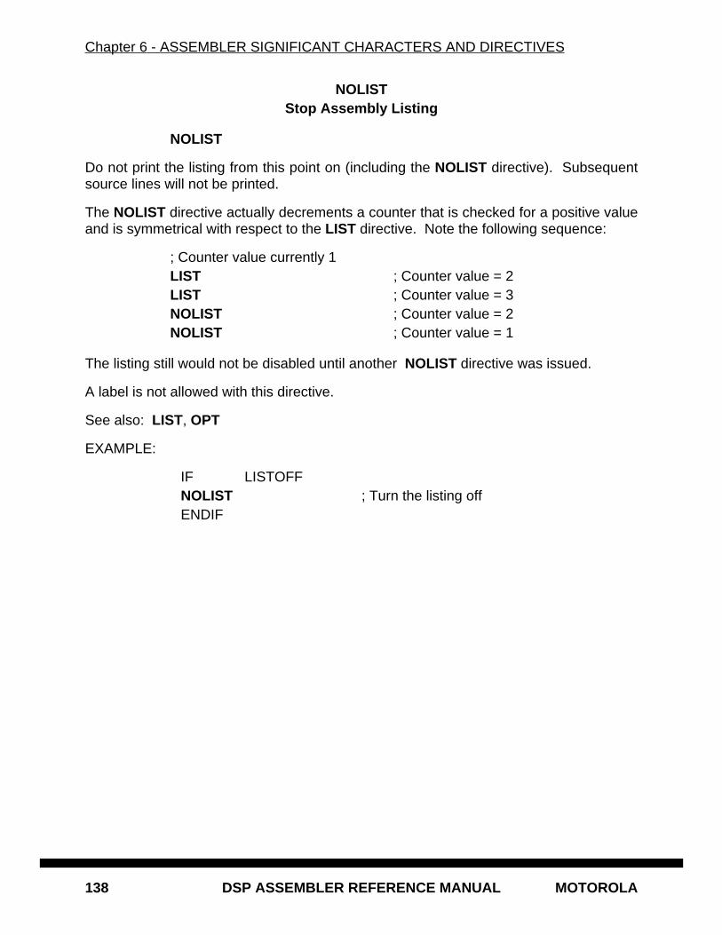
Chapter 6 - ASSEMBLER SIGNIFICANT CHARACTERS AND DIRECTIVES
138 DSP ASSEMBLER REFERENCE MANUAL MOTOROLA
NOLISTStop Assembly Listing
NOLIST
Do not print the listing from this point on (including the NOLIST directive). Subsequentsource lines will not be printed.
The NOLIST directive actually decrements a counter that is checked for a positive valueand is symmetrical with respect to the LIST directive. Note the following sequence:
; Counter value currently 1LIST ; Counter value = 2LIST ; Counter value = 3NOLIST ; Counter value = 2NOLIST ; Counter value = 1
The listing still would not be disabled until another NOLIST directive was issued.
A label is not allowed with this directive.
See also: LIST, OPT
EXAMPLE:
IF LISTOFFNOLIST ; Turn the listing offENDIF
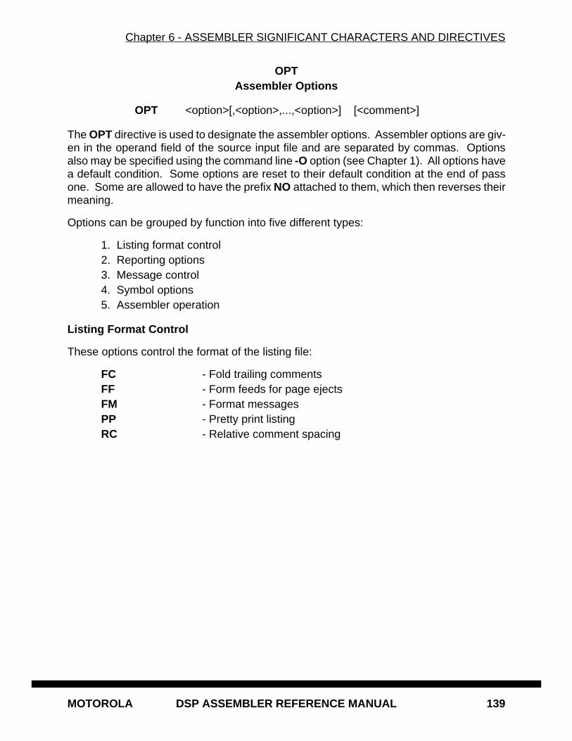
Chapter 6 - ASSEMBLER SIGNIFICANT CHARACTERS AND DIRECTIVES
MOTOROLA DSP ASSEMBLER REFERENCE MANUAL 139
OPTAssembler Options
OPT <option>[,<option>,...,<option>] [<comment>]
The OPT directive is used to designate the assembler options. Assembler options are giv-en in the operand field of the source input file and are separated by commas. Optionsalso may be specified using the command line -O option (see Chapter 1). All options havea default condition. Some options are reset to their default condition at the end of passone. Some are allowed to have the prefix NO attached to them, which then reverses theirmeaning.
Options can be grouped by function into five different types:
1. Listing format control2. Reporting options3. Message control4. Symbol options5. Assembler operation
Listing Format Control
These options control the format of the listing file:
FC - Fold trailing commentsFF - Form feeds for page ejectsFM - Format messagesPP - Pretty print listingRC - Relative comment spacing
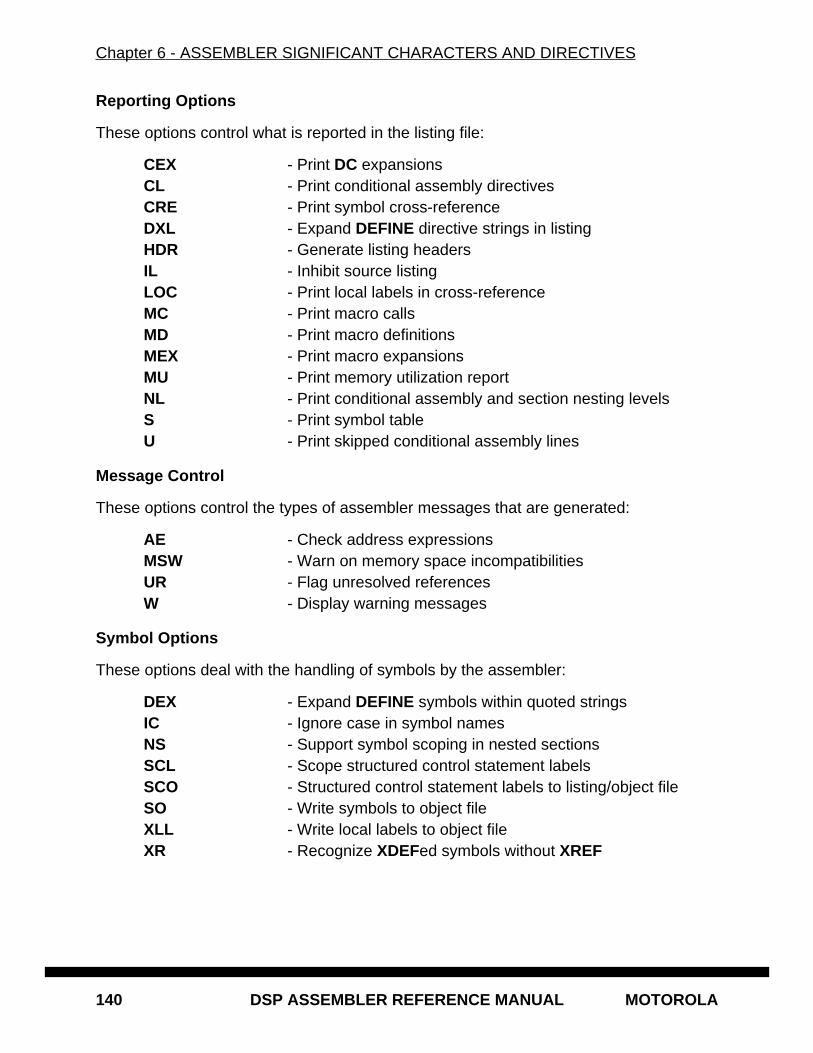
Chapter 6 - ASSEMBLER SIGNIFICANT CHARACTERS AND DIRECTIVES
140 DSP ASSEMBLER REFERENCE MANUAL MOTOROLA
Reporting Options
These options control what is reported in the listing file:
CEX - Print DC expansionsCL - Print conditional assembly directivesCRE - Print symbol cross-referenceDXL - Expand DEFINE directive strings in listingHDR - Generate listing headersIL - Inhibit source listingLOC - Print local labels in cross-referenceMC - Print macro callsMD - Print macro definitionsMEX - Print macro expansionsMU - Print memory utilization reportNL - Print conditional assembly and section nesting levelsS - Print symbol tableU - Print skipped conditional assembly lines
Message Control
These options control the types of assembler messages that are generated:
AE - Check address expressionsMSW - Warn on memory space incompatibilitiesUR - Flag unresolved referencesW - Display warning messages
Symbol Options
These options deal with the handling of symbols by the assembler:
DEX - Expand DEFINE symbols within quoted stringsIC - Ignore case in symbol namesNS - Support symbol scoping in nested sectionsSCL - Scope structured control statement labelsSCO - Structured control statement labels to listing/object fileSO - Write symbols to object fileXLL - Write local labels to object fileXR - Recognize XDEFed symbols without XREF
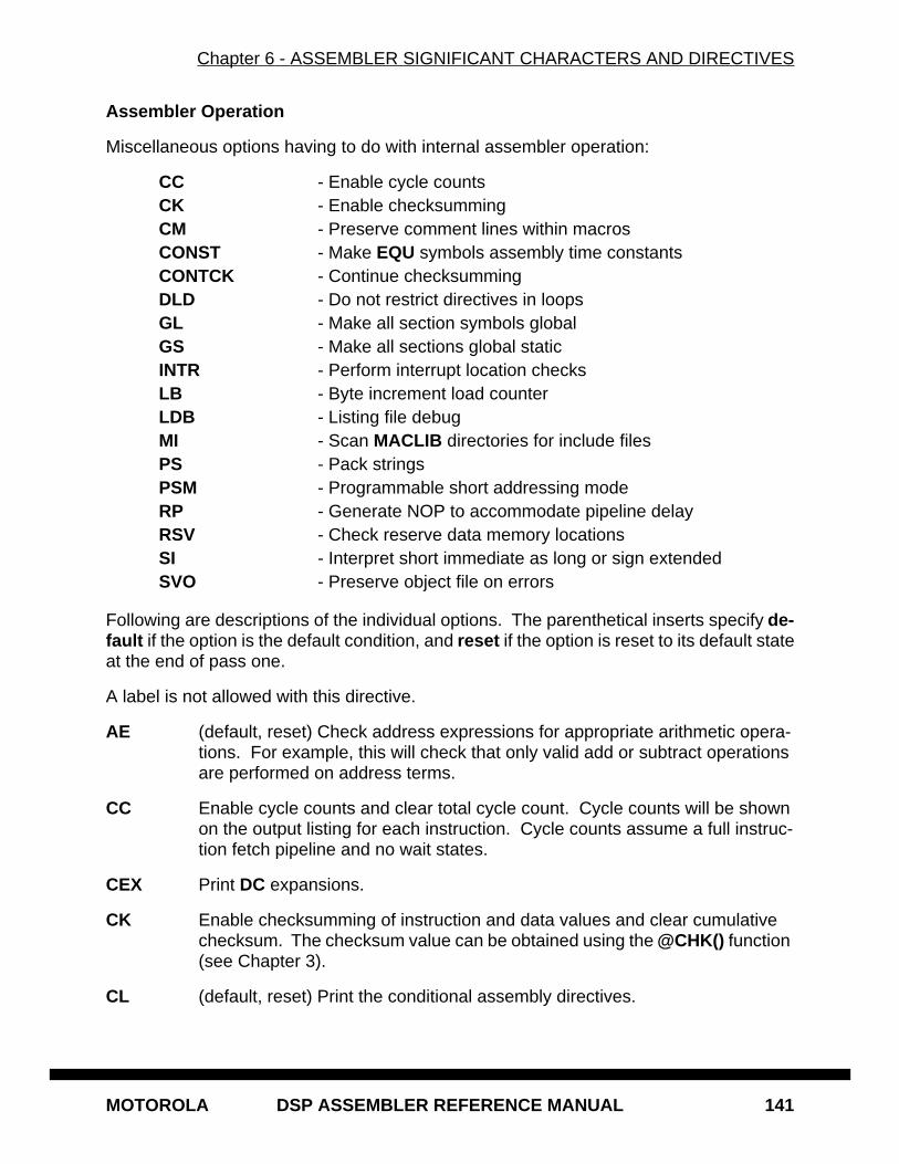
Chapter 6 - ASSEMBLER SIGNIFICANT CHARACTERS AND DIRECTIVES
MOTOROLA DSP ASSEMBLER REFERENCE MANUAL 141
Assembler Operation
Miscellaneous options having to do with internal assembler operation:
CC - Enable cycle countsCK - Enable checksummingCM - Preserve comment lines within macrosCONST - Make EQU symbols assembly time constantsCONTCK - Continue checksummingDLD - Do not restrict directives in loopsGL - Make all section symbols globalGS - Make all sections global staticINTR - Perform interrupt location checksLB - Byte increment load counterLDB - Listing file debugMI - Scan MACLIB directories for include filesPS - Pack stringsPSM - Programmable short addressing modeRP - Generate NOP to accommodate pipeline delayRSV - Check reserve data memory locationsSI - Interpret short immediate as long or sign extendedSVO - Preserve object file on errors
Following are descriptions of the individual options. The parenthetical inserts specify de-fault if the option is the default condition, and reset if the option is reset to its default stateat the end of pass one.
A label is not allowed with this directive.
AE (default, reset) Check address expressions for appropriate arithmetic opera-tions. For example, this will check that only valid add or subtract operations are performed on address terms.
CC Enable cycle counts and clear total cycle count. Cycle counts will be shown on the output listing for each instruction. Cycle counts assume a full instruc-tion fetch pipeline and no wait states.
CEX Print DC expansions.
CK Enable checksumming of instruction and data values and clear cumulative checksum. The checksum value can be obtained using the @CHK() function (see Chapter 3).
CL (default, reset) Print the conditional assembly directives.
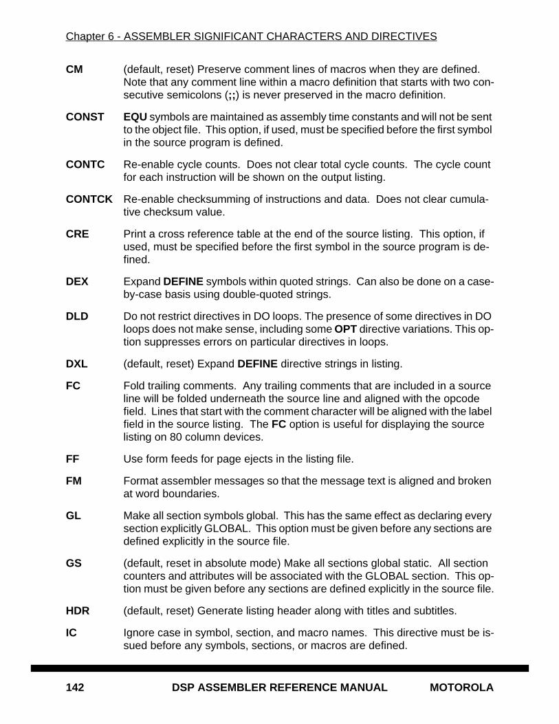
Chapter 6 - ASSEMBLER SIGNIFICANT CHARACTERS AND DIRECTIVES
142 DSP ASSEMBLER REFERENCE MANUAL MOTOROLA
CM (default, reset) Preserve comment lines of macros when they are defined. Note that any comment line within a macro definition that starts with two con-secutive semicolons (;; ) is never preserved in the macro definition.
CONST EQU symbols are maintained as assembly time constants and will not be sent to the object file. This option, if used, must be specified before the first symbol in the source program is defined.
CONTC Re-enable cycle counts. Does not clear total cycle counts. The cycle count for each instruction will be shown on the output listing.
CONTCK Re-enable checksumming of instructions and data. Does not clear cumula-tive checksum value.
CRE Print a cross reference table at the end of the source listing. This option, if used, must be specified before the first symbol in the source program is de-fined.
DEX Expand DEFINE symbols within quoted strings. Can also be done on a case-by-case basis using double-quoted strings.
DLD Do not restrict directives in DO loops. The presence of some directives in DO loops does not make sense, including some OPT directive variations. This op-tion suppresses errors on particular directives in loops.
DXL (default, reset) Expand DEFINE directive strings in listing.
FC Fold trailing comments. Any trailing comments that are included in a source line will be folded underneath the source line and aligned with the opcode field. Lines that start with the comment character will be aligned with the label field in the source listing. The FC option is useful for displaying the source listing on 80 column devices.
FF Use form feeds for page ejects in the listing file.
FM Format assembler messages so that the message text is aligned and broken at word boundaries.
GL Make all section symbols global. This has the same effect as declaring every section explicitly GLOBAL. This option must be given before any sections are defined explicitly in the source file.
GS (default, reset in absolute mode) Make all sections global static. All section counters and attributes will be associated with the GLOBAL section. This op-tion must be given before any sections are defined explicitly in the source file.
HDR (default, reset) Generate listing header along with titles and subtitles.
IC Ignore case in symbol, section, and macro names. This directive must be is-sued before any symbols, sections, or macros are defined.
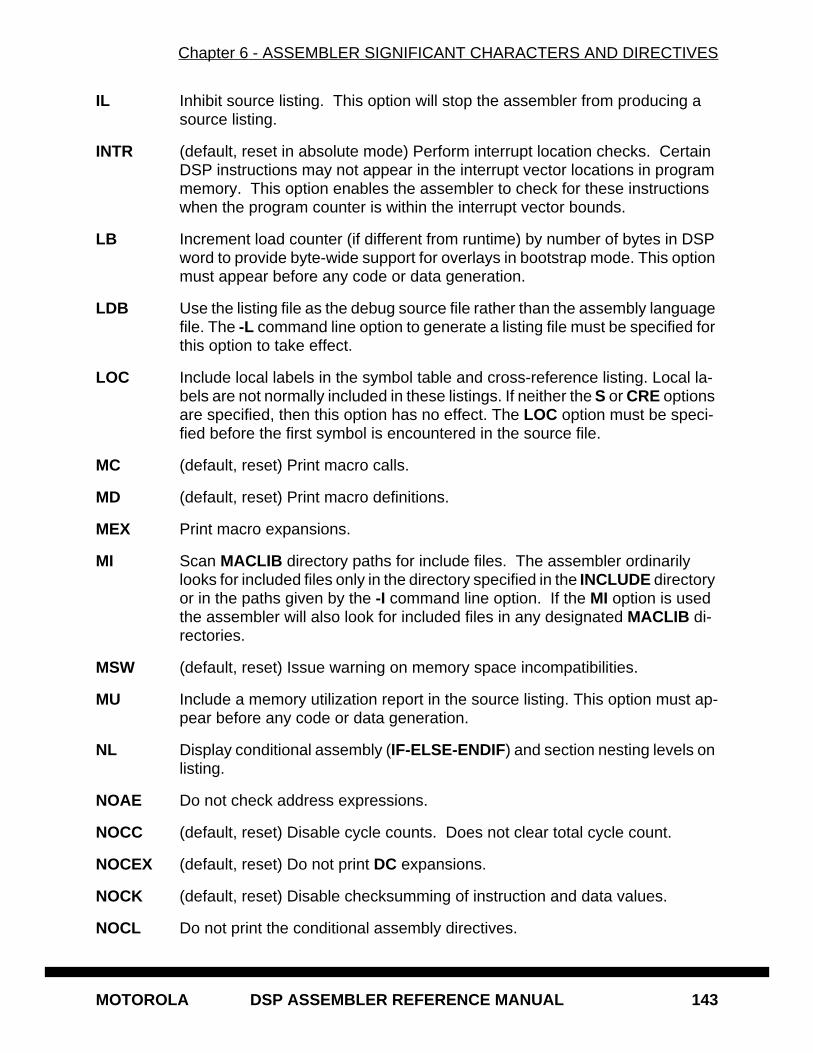
Chapter 6 - ASSEMBLER SIGNIFICANT CHARACTERS AND DIRECTIVES
MOTOROLA DSP ASSEMBLER REFERENCE MANUAL 143
IL Inhibit source listing. This option will stop the assembler from producing a source listing.
INTR (default, reset in absolute mode) Perform interrupt location checks. Certain DSP instructions may not appear in the interrupt vector locations in program memory. This option enables the assembler to check for these instructions when the program counter is within the interrupt vector bounds.
LB Increment load counter (if different from runtime) by number of bytes in DSP word to provide byte-wide support for overlays in bootstrap mode. This option must appear before any code or data generation.
LDB Use the listing file as the debug source file rather than the assembly language file. The -L command line option to generate a listing file must be specified for this option to take effect.
LOC Include local labels in the symbol table and cross-reference listing. Local la-bels are not normally included in these listings. If neither the S or CRE options are specified, then this option has no effect. The LOC option must be speci-fied before the first symbol is encountered in the source file.
MC (default, reset) Print macro calls.
MD (default, reset) Print macro definitions.
MEX Print macro expansions.
MI Scan MACLIB directory paths for include files. The assembler ordinarily looks for included files only in the directory specified in the INCLUDE directory or in the paths given by the -I command line option. If the MI option is used the assembler will also look for included files in any designated MACLIB di-rectories.
MSW (default, reset) Issue warning on memory space incompatibilities.
MU Include a memory utilization report in the source listing. This option must ap-pear before any code or data generation.
NL Display conditional assembly (IF-ELSE-ENDIF) and section nesting levels on listing.
NOAE Do not check address expressions.
NOCC (default, reset) Disable cycle counts. Does not clear total cycle count.
NOCEX (default, reset) Do not print DC expansions.
NOCK (default, reset) Disable checksumming of instruction and data values.
NOCL Do not print the conditional assembly directives.
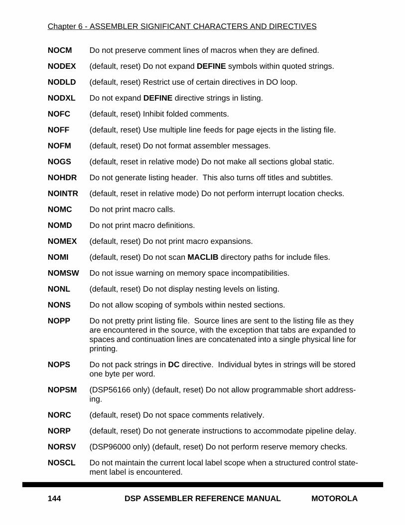
Chapter 6 - ASSEMBLER SIGNIFICANT CHARACTERS AND DIRECTIVES
144 DSP ASSEMBLER REFERENCE MANUAL MOTOROLA
NOCM Do not preserve comment lines of macros when they are defined.
NODEX (default, reset) Do not expand DEFINE symbols within quoted strings.
NODLD (default, reset) Restrict use of certain directives in DO loop.
NODXL Do not expand DEFINE directive strings in listing.
NOFC (default, reset) Inhibit folded comments.
NOFF (default, reset) Use multiple line feeds for page ejects in the listing file.
NOFM (default, reset) Do not format assembler messages.
NOGS (default, reset in relative mode) Do not make all sections global static.
NOHDR Do not generate listing header. This also turns off titles and subtitles.
NOINTR (default, reset in relative mode) Do not perform interrupt location checks.
NOMC Do not print macro calls.
NOMD Do not print macro definitions.
NOMEX (default, reset) Do not print macro expansions.
NOMI (default, reset) Do not scan MACLIB directory paths for include files.
NOMSW Do not issue warning on memory space incompatibilities.
NONL (default, reset) Do not display nesting levels on listing.
NONS Do not allow scoping of symbols within nested sections.
NOPP Do not pretty print listing file. Source lines are sent to the listing file as they are encountered in the source, with the exception that tabs are expanded to spaces and continuation lines are concatenated into a single physical line for printing.
NOPS Do not pack strings in DC directive. Individual bytes in strings will be stored one byte per word.
NOPSM (DSP56166 only) (default, reset) Do not allow programmable short address-ing.
NORC (default, reset) Do not space comments relatively.
NORP (default, reset) Do not generate instructions to accommodate pipeline delay.
NORSV (DSP96000 only) (default, reset) Do not perform reserve memory checks.
NOSCL Do not maintain the current local label scope when a structured control state-ment label is encountered.
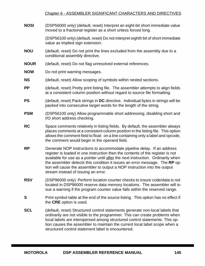
Chapter 6 - ASSEMBLER SIGNIFICANT CHARACTERS AND DIRECTIVES
MOTOROLA DSP ASSEMBLER REFERENCE MANUAL 145
NOSI (DSP56000 only) (default, reset) Interpret an eight-bit short immediate value moved to a fractional register as a short unless forced long.
(DSP56100 only) (default, reset) Do not interpret eighth bit of short immediate value as implied sign extension.
NOU (default, reset) Do not print the lines excluded from the assembly due to a conditional assembly directive.
NOUR (default, reset) Do not flag unresolved external references.
NOW Do not print warning messages.
NS (default, reset) Allow scoping of symbols within nested sections.
PP (default, reset) Pretty print listing file. The assembler attempts to align fields at a consistent column position without regard to source file formatting.
PS (default, reset) Pack strings in DC directive. Individual bytes in strings will be packed into consecutive target words for the length of the string.
PSM (DSP56100 only) Allow programmable short addressing, disabling short and I/O short address checking.
RC Space comments relatively in listing fields. By default, the assembler always places comments at a consistent column position in the listing file. This option allows the comment field to float: on a line containing only a label and opcode, the comment would begin in the operand field.
RP Generate NOP instructions to accommodate pipeline delay. If an address register is loaded in one instruction then the contents of the register is not available for use as a pointer until after the next instruction. Ordinarily when the assembler detects this condition it issues an error message. The RP op-tion will cause the assembler to output a NOP instruction into the output stream instead of issuing an error.
RSV (DSP96000 only) Perform location counter checks to insure code/data is not located in DSP96000 reserve data memory locations. The assembler will is-sue a warning if the program counter value falls within the reserved range.
S Print symbol table at the end of the source listing. This option has no effect if the CRE option is used.
SCL (default, reset) Structured control statements generate non-local labels that ordinarily are not visible to the programmer. This can create problems when local labels are interspersed among structured control statements. This op-tion causes the assembler to maintain the current local label scope when a structured control statement label is encountered.
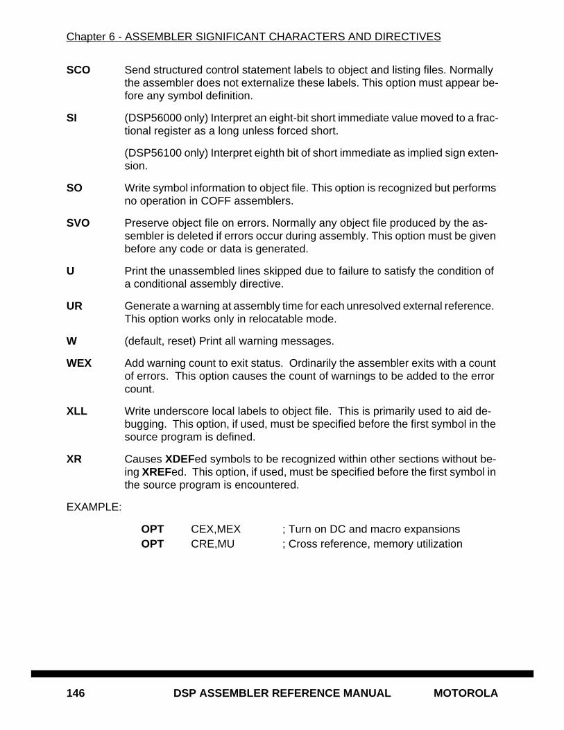
Chapter 6 - ASSEMBLER SIGNIFICANT CHARACTERS AND DIRECTIVES
146 DSP ASSEMBLER REFERENCE MANUAL MOTOROLA
SCO Send structured control statement labels to object and listing files. Normally the assembler does not externalize these labels. This option must appear be-fore any symbol definition.
SI (DSP56000 only) Interpret an eight-bit short immediate value moved to a frac-tional register as a long unless forced short.
(DSP56100 only) Interpret eighth bit of short immediate as implied sign exten-sion.
SO Write symbol information to object file. This option is recognized but performs no operation in COFF assemblers.
SVO Preserve object file on errors. Normally any object file produced by the as-sembler is deleted if errors occur during assembly. This option must be given before any code or data is generated.
U Print the unassembled lines skipped due to failure to satisfy the condition of a conditional assembly directive.
UR Generate a warning at assembly time for each unresolved external reference. This option works only in relocatable mode.
W (default, reset) Print all warning messages.
WEX Add warning count to exit status. Ordinarily the assembler exits with a count of errors. This option causes the count of warnings to be added to the error count.
XLL Write underscore local labels to object file. This is primarily used to aid de-bugging. This option, if used, must be specified before the first symbol in the source program is defined.
XR Causes XDEFed symbols to be recognized within other sections without be-ing XREFed. This option, if used, must be specified before the first symbol in the source program is encountered.
EXAMPLE:
OPT CEX,MEX ; Turn on DC and macro expansionsOPT CRE,MU ; Cross reference, memory utilization
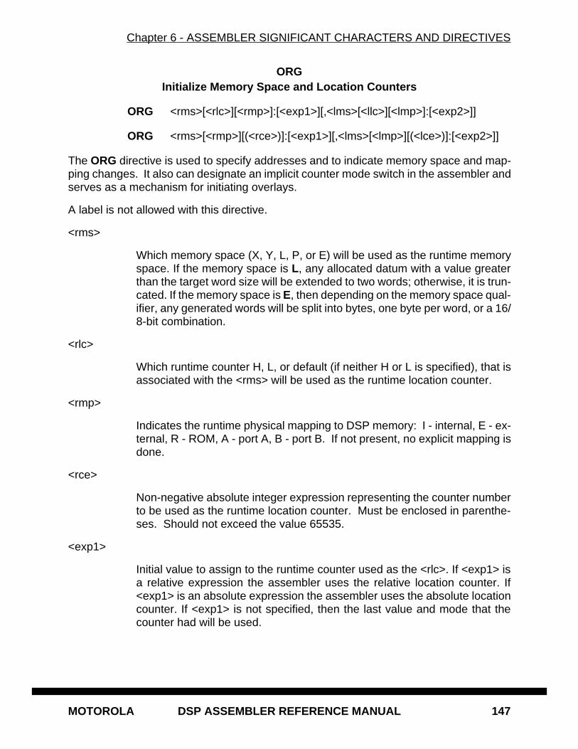
Chapter 6 - ASSEMBLER SIGNIFICANT CHARACTERS AND DIRECTIVES
MOTOROLA DSP ASSEMBLER REFERENCE MANUAL 147
ORGInitialize Memory Space and Location Counters
ORG <rms>[<rlc>][<rmp>]:[<exp1>][,<lms>[<llc>][<lmp>]:[<exp2>]]
ORG <rms>[<rmp>][(<rce>)]:[<exp1>][,<lms>[<lmp>][(<lce>)]:[<exp2>]]
The ORG directive is used to specify addresses and to indicate memory space and map-ping changes. It also can designate an implicit counter mode switch in the assembler andserves as a mechanism for initiating overlays.
A label is not allowed with this directive.
<rms>
Which memory space (X, Y, L, P, or E) will be used as the runtime memoryspace. If the memory space is L, any allocated datum with a value greaterthan the target word size will be extended to two words; otherwise, it is trun-cated. If the memory space is E, then depending on the memory space qual-ifier, any generated words will be split into bytes, one byte per word, or a 16/8-bit combination.
<rlc>
Which runtime counter H, L, or default (if neither H or L is specified), that isassociated with the <rms> will be used as the runtime location counter.
<rmp>
Indicates the runtime physical mapping to DSP memory: I - internal, E - ex-ternal, R - ROM, A - port A, B - port B. If not present, no explicit mapping isdone.
<rce>
Non-negative absolute integer expression representing the counter numberto be used as the runtime location counter. Must be enclosed in parenthe-ses. Should not exceed the value 65535.
<exp1>
Initial value to assign to the runtime counter used as the <rlc>. If <exp1> isa relative expression the assembler uses the relative location counter. If<exp1> is an absolute expression the assembler uses the absolute locationcounter. If <exp1> is not specified, then the last value and mode that thecounter had will be used.
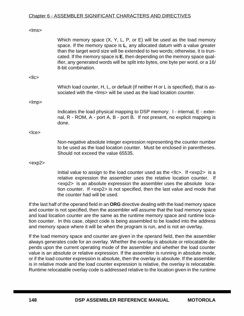
Chapter 6 - ASSEMBLER SIGNIFICANT CHARACTERS AND DIRECTIVES
148 DSP ASSEMBLER REFERENCE MANUAL MOTOROLA
<lms>
Which memory space (X, Y, L, P, or E) will be used as the load memoryspace. If the memory space is L, any allocated datum with a value greaterthan the target word size will be extended to two words; otherwise, it is trun-cated. If the memory space is E, then depending on the memory space qual-ifier, any generated words will be split into bytes, one byte per word, or a 16/8-bit combination.
<llc>
Which load counter, H, L, or default (if neither H or L is specified), that is as-sociated with the <lms> will be used as the load location counter.
<lmp>
Indicates the load physical mapping to DSP memory: I - internal, E - exter-nal, R - ROM, A - port A, B - port B. If not present, no explicit mapping isdone.
<lce>
Non-negative absolute integer expression representing the counter numberto be used as the load location counter. Must be enclosed in parentheses.Should not exceed the value 65535.
<exp2>
Initial value to assign to the load counter used as the <llc>. If <exp2> is arelative expression the assembler uses the relative location counter. If<exp2> is an absolute expression the assembler uses the absolute loca-tion counter. If <exp2> is not specified, then the last value and mode thatthe counter had will be used.
If the last half of the operand field in an ORG directive dealing with the load memory spaceand counter is not specified, then the assembler will assume that the load memory spaceand load location counter are the same as the runtime memory space and runtime loca-tion counter. In this case, object code is being assembled to be loaded into the addressand memory space where it will be when the program is run, and is not an overlay.
If the load memory space and counter are given in the operand field, then the assembleralways generates code for an overlay. Whether the overlay is absolute or relocatable de-pends upon the current operating mode of the assembler and whether the load countervalue is an absolute or relative expression. If the assembler is running in absolute mode,or if the load counter expression is absolute, then the overlay is absolute. If the assembleris in relative mode and the load counter expression is relative, the overlay is relocatable.Runtime relocatable overlay code is addressed relative to the location given in the runtime
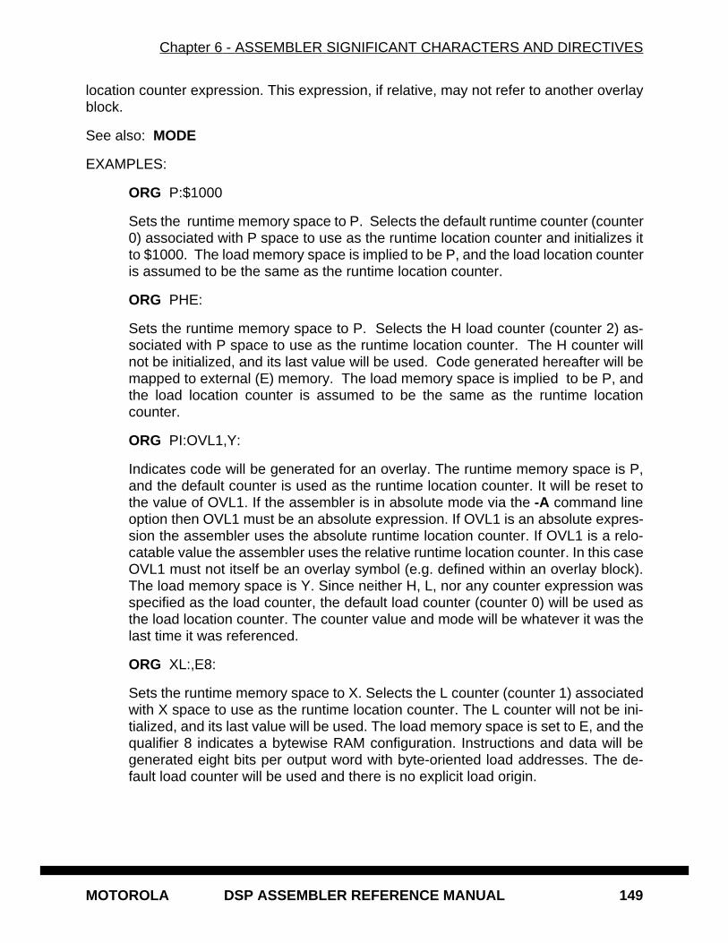
Chapter 6 - ASSEMBLER SIGNIFICANT CHARACTERS AND DIRECTIVES
MOTOROLA DSP ASSEMBLER REFERENCE MANUAL 149
location counter expression. This expression, if relative, may not refer to another overlayblock.
See also: MODE
EXAMPLES:
ORG P:$1000
Sets the runtime memory space to P. Selects the default runtime counter (counter0) associated with P space to use as the runtime location counter and initializes itto $1000. The load memory space is implied to be P, and the load location counteris assumed to be the same as the runtime location counter.
ORG PHE:
Sets the runtime memory space to P. Selects the H load counter (counter 2) as-sociated with P space to use as the runtime location counter. The H counter willnot be initialized, and its last value will be used. Code generated hereafter will bemapped to external (E) memory. The load memory space is implied to be P, andthe load location counter is assumed to be the same as the runtime locationcounter.
ORG PI:OVL1,Y:
Indicates code will be generated for an overlay. The runtime memory space is P,and the default counter is used as the runtime location counter. It will be reset tothe value of OVL1. If the assembler is in absolute mode via the -A command lineoption then OVL1 must be an absolute expression. If OVL1 is an absolute expres-sion the assembler uses the absolute runtime location counter. If OVL1 is a relo-catable value the assembler uses the relative runtime location counter. In this caseOVL1 must not itself be an overlay symbol (e.g. defined within an overlay block).The load memory space is Y. Since neither H, L, nor any counter expression wasspecified as the load counter, the default load counter (counter 0) will be used asthe load location counter. The counter value and mode will be whatever it was thelast time it was referenced.
ORG XL:,E8:
Sets the runtime memory space to X. Selects the L counter (counter 1) associatedwith X space to use as the runtime location counter. The L counter will not be ini-tialized, and its last value will be used. The load memory space is set to E, and thequalifier 8 indicates a bytewise RAM configuration. Instructions and data will begenerated eight bits per output word with byte-oriented load addresses. The de-fault load counter will be used and there is no explicit load origin.
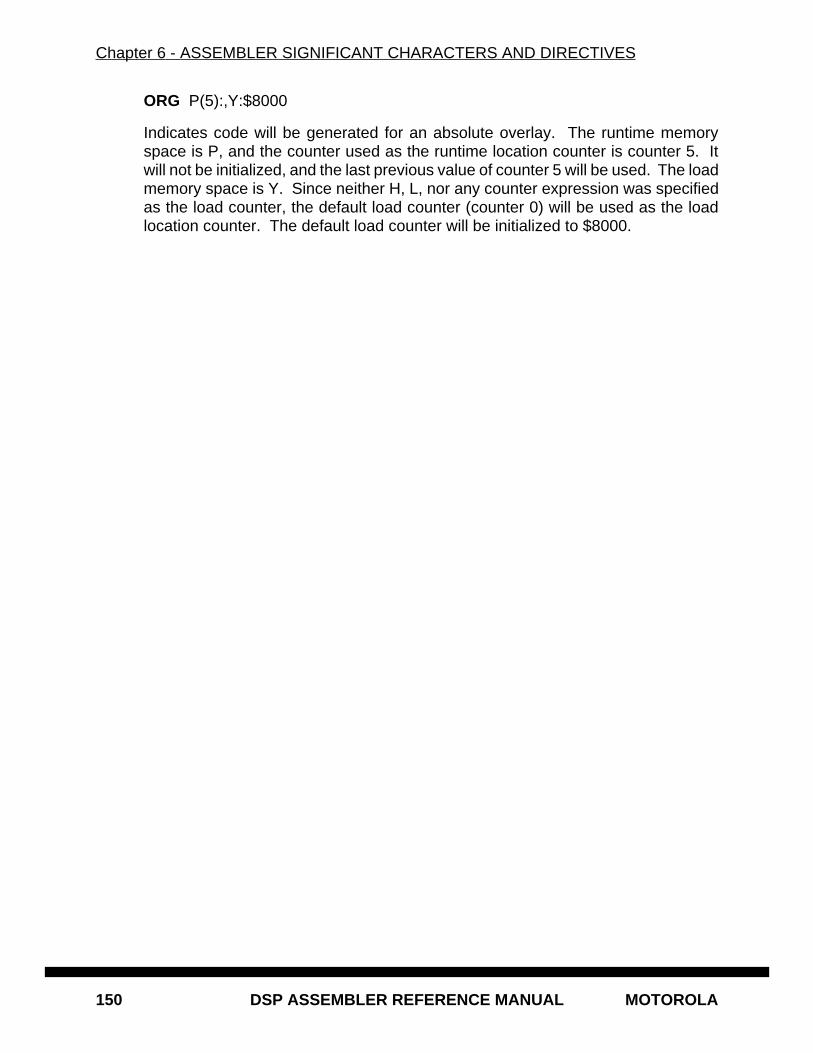
Chapter 6 - ASSEMBLER SIGNIFICANT CHARACTERS AND DIRECTIVES
150 DSP ASSEMBLER REFERENCE MANUAL MOTOROLA
ORG P(5):,Y:$8000
Indicates code will be generated for an absolute overlay. The runtime memoryspace is P, and the counter used as the runtime location counter is counter 5. Itwill not be initialized, and the last previous value of counter 5 will be used. The loadmemory space is Y. Since neither H, L, nor any counter expression was specifiedas the load counter, the default load counter (counter 0) will be used as the loadlocation counter. The default load counter will be initialized to $8000.
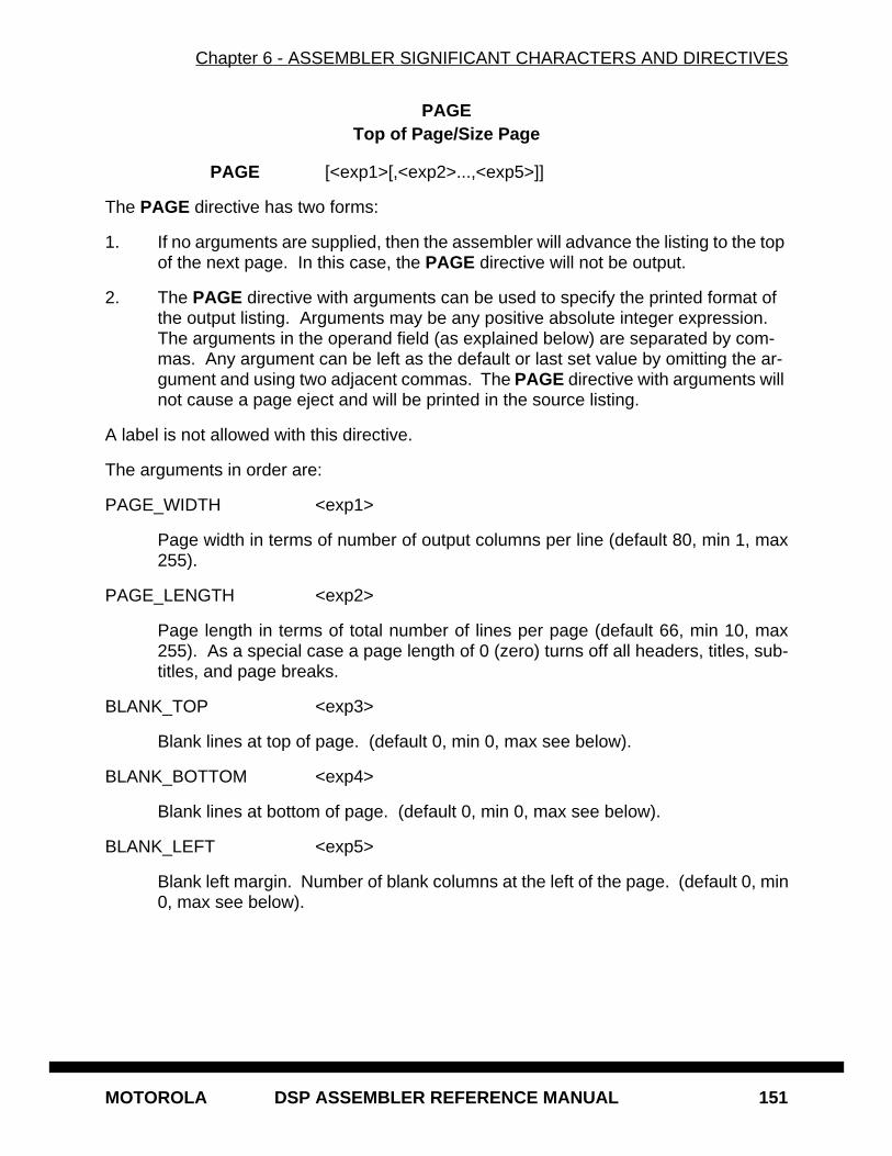
Chapter 6 - ASSEMBLER SIGNIFICANT CHARACTERS AND DIRECTIVES
MOTOROLA DSP ASSEMBLER REFERENCE MANUAL 151
PAGETop of Page/Size Page
PAGE [<exp1>[,<exp2>...,<exp5>]]
The PAGE directive has two forms:
1. If no arguments are supplied, then the assembler will advance the listing to the top of the next page. In this case, the PAGE directive will not be output.
2. The PAGE directive with arguments can be used to specify the printed format of the output listing. Arguments may be any positive absolute integer expression. The arguments in the operand field (as explained below) are separated by com-mas. Any argument can be left as the default or last set value by omitting the ar-gument and using two adjacent commas. The PAGE directive with arguments will not cause a page eject and will be printed in the source listing.
A label is not allowed with this directive.
The arguments in order are:
PAGE_WIDTH <exp1>
Page width in terms of number of output columns per line (default 80, min 1, max255).
PAGE_LENGTH <exp2>
Page length in terms of total number of lines per page (default 66, min 10, max255). As a special case a page length of 0 (zero) turns off all headers, titles, sub-titles, and page breaks.
BLANK_TOP <exp3>
Blank lines at top of page. (default 0, min 0, max see below).
BLANK_BOTTOM <exp4>
Blank lines at bottom of page. (default 0, min 0, max see below).
BLANK_LEFT <exp5>
Blank left margin. Number of blank columns at the left of the page. (default 0, min0, max see below).
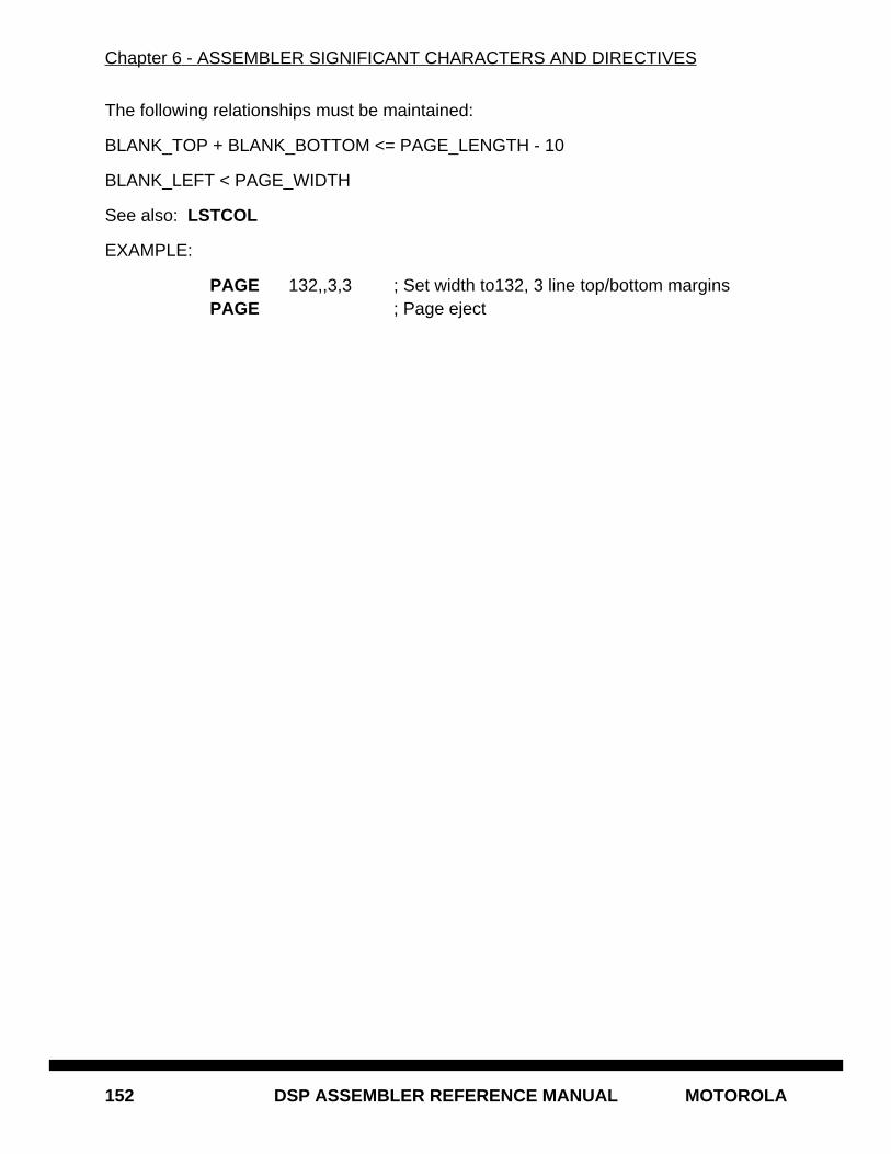
Chapter 6 - ASSEMBLER SIGNIFICANT CHARACTERS AND DIRECTIVES
152 DSP ASSEMBLER REFERENCE MANUAL MOTOROLA
The following relationships must be maintained:
BLANK_TOP + BLANK_BOTTOM <= PAGE_LENGTH - 10
BLANK_LEFT < PAGE_WIDTH
See also: LSTCOL
EXAMPLE:
PAGE 132,,3,3 ; Set width to132, 3 line top/bottom marginsPAGE ; Page eject
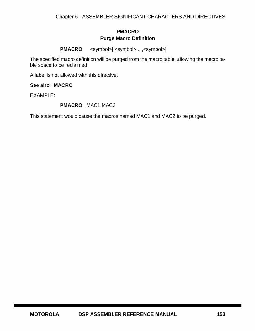
Chapter 6 - ASSEMBLER SIGNIFICANT CHARACTERS AND DIRECTIVES
MOTOROLA DSP ASSEMBLER REFERENCE MANUAL 153
PMACROPurge Macro Definition
PMACRO <symbol>[,<symbol>,...,<symbol>]
The specified macro definition will be purged from the macro table, allowing the macro ta-ble space to be reclaimed.
A label is not allowed with this directive.
See also: MACRO
EXAMPLE:
PMACRO MAC1,MAC2
This statement would cause the macros named MAC1 and MAC2 to be purged.
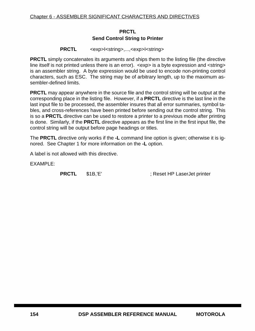
Chapter 6 - ASSEMBLER SIGNIFICANT CHARACTERS AND DIRECTIVES
154 DSP ASSEMBLER REFERENCE MANUAL MOTOROLA
PRCTLSend Control String to Printer
PRCTL <exp>I<string>,...,<exp>I<string>
PRCTL simply concatenates its arguments and ships them to the listing file (the directiveline itself is not printed unless there is an error). <exp> is a byte expression and <string>is an assembler string. A byte expression would be used to encode non-printing controlcharacters, such as ESC. The string may be of arbitrary length, up to the maximum as-sembler-defined limits.
PRCTL may appear anywhere in the source file and the control string will be output at thecorresponding place in the listing file. However, if a PRCTL directive is the last line in thelast input file to be processed, the assembler insures that all error summaries, symbol ta-bles, and cross-references have been printed before sending out the control string. Thisis so a PRCTL directive can be used to restore a printer to a previous mode after printingis done. Similarly, if the PRCTL directive appears as the first line in the first input file, thecontrol string will be output before page headings or titles.
The PRCTL directive only works if the -L command line option is given; otherwise it is ig-nored. See Chapter 1 for more information on the -L option.
A label is not allowed with this directive.
EXAMPLE:
PRCTL $1B,'E' ; Reset HP LaserJet printer
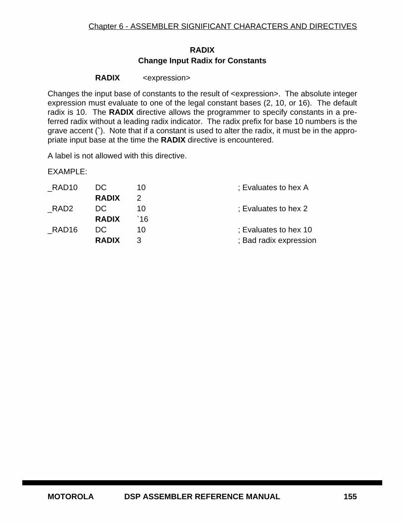
Chapter 6 - ASSEMBLER SIGNIFICANT CHARACTERS AND DIRECTIVES
MOTOROLA DSP ASSEMBLER REFERENCE MANUAL 155
RADIXChange Input Radix for Constants
RADIX <expression>
Changes the input base of constants to the result of <expression>. The absolute integerexpression must evaluate to one of the legal constant bases (2, 10, or 16). The defaultradix is 10. The RADIX directive allows the programmer to specify constants in a pre-ferred radix without a leading radix indicator. The radix prefix for base 10 numbers is thegrave accent (`). Note that if a constant is used to alter the radix, it must be in the appro-priate input base at the time the RADIX directive is encountered.
A label is not allowed with this directive.
EXAMPLE:
_RAD10 DC 10 ; Evaluates to hex ARADIX 2
_RAD2 DC 10 ; Evaluates to hex 2RADIX `16
_RAD16 DC 10 ; Evaluates to hex 10RADIX 3 ; Bad radix expression
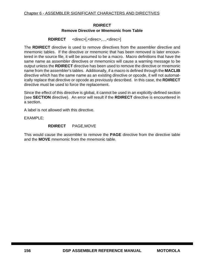
Chapter 6 - ASSEMBLER SIGNIFICANT CHARACTERS AND DIRECTIVES
156 DSP ASSEMBLER REFERENCE MANUAL MOTOROLA
RDIRECTRemove Directive or Mnemonic from Table
RDIRECT <direc>[,<direc>,...,<direc>]
The RDIRECT directive is used to remove directives from the assembler directive andmnemonic tables. If the directive or mnemonic that has been removed is later encoun-tered in the source file, it will be assumed to be a macro. Macro definitions that have thesame name as assembler directives or mnemonics will cause a warning message to beoutput unless the RDIRECT directive has been used to remove the directive or mnemonicname from the assembler’s tables. Additionally, if a macro is defined through the MACLIBdirective which has the same name as an existing directive or opcode, it will not automat-ically replace that directive or opcode as previously described. In this case, the RDIRECTdirective must be used to force the replacement.
Since the effect of this directive is global, it cannot be used in an explicitly-defined section(see SECTION directive). An error will result if the RDIRECT directive is encountered ina section.
A label is not allowed with this directive.
EXAMPLE:
RDIRECT PAGE,MOVE
This would cause the assembler to remove the PAGE directive from the directive tableand the MOVE mnemonic from the mnemonic table.
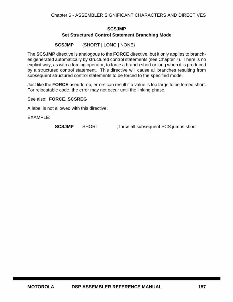
Chapter 6 - ASSEMBLER SIGNIFICANT CHARACTERS AND DIRECTIVES
MOTOROLA DSP ASSEMBLER REFERENCE MANUAL 157
SCSJMPSet Structured Control Statement Branching Mode
SCSJMP {SHORT | LONG | NONE}
The SCSJMP directive is analogous to the FORCE directive, but it only applies to branch-es generated automatically by structured control statements (see Chapter 7). There is noexplicit way, as with a forcing operator, to force a branch short or long when it is producedby a structured control statement. This directive will cause all branches resulting fromsubsequent structured control statements to be forced to the specified mode.
Just like the FORCE pseudo-op, errors can result if a value is too large to be forced short.For relocatable code, the error may not occur until the linking phase.
See also: FORCE, SCSREG
A label is not allowed with this directive.
EXAMPLE:
SCSJMP SHORT ; force all subsequent SCS jumps short
Chapter 6 - ASSEMBLER SIGNIFICANT CHARACTERS AND DIRECTIVES
158 DSP ASSEMBLER REFERENCE MANUAL MOTOROLA
SCSREGReassign Structured Control Statement Registers
SCSREG [<srcreg>[,<dstreg>[,<tmpreg>[,<extreg>]]]]
The SCSREG directive reassigns the registers used by structured control statement(SCS) directives (see Chapter 7). It is convenient for reclaiming default SCS registerswhen they are needed as application operands within a structured control construct. <sr-creg> is ordinarily the source register for SCS data moves. <dstreg> is the destinationregister. <tmpreg> is a temporary register for swapping SCS operands. <extreg> is anextra register for complex SCS operations. With no arguments SCSREG resets the SCSregisters to their default assignments.
The SCSREG directive should be used judiciously to avoid register context errors duringSCS expansion. Source and destination registers may not necessarily be used strictly assource and destination operands. The assembler does no checking of reassigned regis-ters beyond validity for the target processor. Errors can result when a structured controlstatement is expanded and an improper register reassignment has occurred. It is recom-mended that the MEX option (see the OPT directive) be used to examine structured con-trol statement expansion for relevant constructs to determine default register usage andapplicable reassignment strategies.
See also: OPT (MEX), SCSJMP
A label is not allowed with this directive.
EXAMPLE:
SCSREG Y0,B ; reassign SCS source and dest. registers
Chapter 6 - ASSEMBLER SIGNIFICANT CHARACTERS AND DIRECTIVES
MOTOROLA DSP ASSEMBLER REFERENCE MANUAL 159
SECTIONStart Section
SECTION <symbol> [GLOBAL | STATIC | LOCAL]..<section source statements>..ENDSEC
The SECTION directive defines the start of a section. All symbols that are defined withina section have the <symbol> associated with them as their section name. This serves toprotect them from like-named symbols elsewhere in the program. By default, a symboldefined inside any given section is private to that section unless the GLOBAL or LOCALqualifier accompanies the SECTION directive.
Any code or data inside a section is considered an indivisible block with respect to relo-cation. Code or data associated with a section is independently relocatable within thememory space to which it is bound, unless the STATIC qualifier follows the SECTION di-rective on the instruction line.
Symbols within a section are generally distinct from other symbols used elsewhere in thesource program, even if the symbol name is the same. This is true as long as the sectionname associated with each symbol is unique, the symbol is not declared public (XDEF/GLOBAL ), and the GLOBAL or LOCAL qualifier is not used in the section declaration.Symbols that are defined outside of a section are considered global symbols and have noexplicit section name associated with them. Global symbols may be referenced freelyfrom inside or outside of any section, as long as the global symbol name does not conflictwith another symbol by the same name in a given section.
If the GLOBAL qualifier follows the <section name> in the SECTION directive, then allsymbols defined in the section until the next ENDSEC directive are considered global.The effect is as if every symbol in the section were declared with GLOBAL . This is usefulwhen a section needs to be independently relocatable, but data hiding is not desired.
If the STATIC qualifier follows the <section name> in the SECTION directive, then all codeand data defined in the section until the next ENDSEC directive are relocated in terms ofthe immediately enclosing section. The effect with respect to relocation is as if all codeand data in the section were defined within the parent section. This is useful when a sec-tion needs data hiding, but independent relocation is not required.
If the LOCAL qualifier follows the <section name> in the SECTION directive, then all sym-bols defined in the section until the next ENDSEC directive are visible to the immediatelyenclosing section. The effect is as if every symbol in the section were defined within theparent section. This is useful when a section needs to be independently relocatable, butdata hiding within an enclosing section is not required.
Chapter 6 - ASSEMBLER SIGNIFICANT CHARACTERS AND DIRECTIVES
160 DSP ASSEMBLER REFERENCE MANUAL MOTOROLA
The division of a program into sections controls not only labels and symbols, but also mac-ros and DEFINE directive symbols. Macros defined within a section are private to thatsection and are distinct from macros defined in other sections even if they have the samemacro name. Macros defined outside of sections are considered global and may be usedwithin any section. Similarly, DEFINE directive symbols defined within a section are pri-vate to that section and DEFINE directive symbols defined outside of any section are glo-bally applied. There are no directives that correspond to XDEF for macros or DEFINEsymbols, and therefore, macros and DEFINE symbols defined in a section can never beaccessed globally. If global accessibility is desired, the macros and DEFINE symbolsshould be defined outside of any section.
Sections can be nested to any level. When the assembler encounters a nested section,the current section is stacked and the new section is used. When the ENDSEC directiveof the nested section is encountered, the assembler restores the old section and uses it.The ENDSEC directive always applies to the most previous SECTION directive. Nestingsections provides a measure of scoping for symbol names, in that symbols defined withina given section are visible to other sections nested within it. For example, if section B isnested inside section A, then a symbol defined in section A can be used in section B with-out XDEFing in section A or XREFing in section B. This scoping behavior can be turnedoff and on with the NONS and NS options respectively (see the OPT directive, this chap-ter).
Sections may also be split into separate parts. That is, <section name> can be used mul-tiple times with SECTION and ENDSEC directive pairs. If this occurs, then these separate(but identically named) sections can access each others symbols freely without the useof the XREF and XDEF directives. If the XDEF and XREF directives are used within onesection, they apply to all sections with the same section name. The reuse of the sectionname is allowed to permit the program source to be arranged in an arbitrary manner (forexample, all statements that reserve X space storage locations grouped together), but re-tain the privacy of the symbols for each section.
When the assembler operates in relative mode (the default), sections act as the basicgrouping for relocation of code and data blocks. For every section defined in the sourcea set of location counters is allocated for each DSP memory space. These counters areused to maintain offsets of data and instructions relative to the beginning of the section.At link time sections can be relocated to an absolute address, loaded in a particular order,or linked contiguously as specified by the programmer. Sections which are split into partsor among files are logically recombined so that each section can be relocated as a unit.
Sections may be relocatable or absolute. In the assembler absolute mode (command line-A option) all sections are considered absolute. A full set of locations counters is reservedfor each absolute section unless the GS option is given (see the OPT directive, this chap-ter). In relative mode, all sections are initially relocatable. However, a section or a part
Chapter 6 - ASSEMBLER SIGNIFICANT CHARACTERS AND DIRECTIVES
MOTOROLA DSP ASSEMBLER REFERENCE MANUAL 161
of a section may be made absolute either implicitly by using the ORG directive, or explic-itly through use of the MODE directive.
A label is not allowed with this directive.
See also: MODE, ORG, GLOBAL , LOCAL , XDEF, XREF
EXAMPLE:
SECTION TABLES ; TABLES will be the section name
Chapter 6 - ASSEMBLER SIGNIFICANT CHARACTERS AND DIRECTIVES
162 DSP ASSEMBLER REFERENCE MANUAL MOTOROLA
SETSet Symbol to a Value
<label> SET <expression>
SET <label> <expression>
The SET directive is used to assign the value of the expression in the operand field to thelabel. The SET directive functions somewhat like the EQU directive. However, labels de-fined via the SET directive can have their values redefined in another part of the program(but only through the use of another SET directive). The SET directive is useful in estab-lishing temporary or reusable counters within macros. The expression in the operand fieldof a SET must be absolute and cannot include a symbol that is not yet defined (no forwardreferences are allowed).
See also: EQU, GSET
EXAMPLE:
COUNT SET 0 ; INITIALIZE COUNT
Chapter 6 - ASSEMBLER SIGNIFICANT CHARACTERS AND DIRECTIVES
MOTOROLA DSP ASSEMBLER REFERENCE MANUAL 163
STITLEInitialize Program Sub-Title
STITLE [<string>]
The STITLE directive initializes the program subtitle to the string in the operand field. Thesubtitle will be printed on the top of all succeeding pages until another STITLE directiveis encountered. The subtitle is initially blank. The STITLE directive will not be printed inthe source listing. An STITLE directive with no string argument will cause the current sub-title to be blank.
A label is not allowed with this directive.
See also: TITLE
EXAMPLE:
STITLE 'COLLECT SAMPLES'
Chapter 6 - ASSEMBLER SIGNIFICANT CHARACTERS AND DIRECTIVES
164 DSP ASSEMBLER REFERENCE MANUAL MOTOROLA
SYMOBJWrite Symbol Information to Object File
SYMOBJ <symbol>[,<symbol>,...,<symbol>]
The SYMOBJ directive causes information for each <symbol> to be written to the objectfile. This directive is recognized but currently performs no operation in COFF assemblers(see Appendix E, MOTOROLA DSP OBJECT FILE FORMAT (COFF)).
A label is not allowed with this directive.
EXAMPLE:
SYMOBJ XSTART,HIRTN,ERRPROC
Chapter 6 - ASSEMBLER SIGNIFICANT CHARACTERS AND DIRECTIVES
MOTOROLA DSP ASSEMBLER REFERENCE MANUAL 165
TABSSet Listing Tab Stops
TABS <tabstops>
The TABS directive allows resetting the listing file tab stops from the default value of 8.
A label is not allowed with this directive.
See also: LSTCOL
EXAMPLE:
TABS 4 ; Set listing file tab stops to 4
Chapter 6 - ASSEMBLER SIGNIFICANT CHARACTERS AND DIRECTIVES
166 DSP ASSEMBLER REFERENCE MANUAL MOTOROLA
TITLEInitialize Program Title
TITLE [<string>]
The TITLE directive initializes the program title to the string in the operand field. The pro-gram title will be printed on the top of all succeeding pages until another TITLE directiveis encountered. The title is initially blank. The TITLE directive will not be printed in thesource listing. A TITLE directive with no string argument will cause the current title to beblank.
A label is not allowed with this directive.
See also: STITLE
EXAMPLE:
TITLE 'FIR FILTER'
Chapter 6 - ASSEMBLER SIGNIFICANT CHARACTERS AND DIRECTIVES
MOTOROLA DSP ASSEMBLER REFERENCE MANUAL 167
UNDEFUndefine DEFINE Symbol
UNDEF [<symbol>]
The UNDEF directive causes the substitution string associated with <symbol> to be re-leased, and <symbol> will no longer represent a valid DEFINE substitution. See the DE-FINE directive for more information.
A label is not allowed with this directive.
See also: DEFINE
EXAMPLE:
UNDEF DEBUG ; UNDEFINES THE DEBUG SUBSTITUTION STRING
Chapter 6 - ASSEMBLER SIGNIFICANT CHARACTERS AND DIRECTIVES
168 DSP ASSEMBLER REFERENCE MANUAL MOTOROLA
WARNProgrammer Generated Warning
WARN [{<str>|<exp>}[,{<str>|<exp>},...,{<str>|<exp>}]]
The WARN directive will cause a warning message to be output by the assembler. Thetotal warning count will be incremented as with any other warning. The WARN directiveis normally used in conjunction with conditional assembly directives for exceptional con-dition checking. The assembly proceeds normally after the warning has been printed. Anarbitrary number of strings and expressions, in any order but separated by commas withno intervening white space, can be specified optionally to describe the nature of the gen-erated warning.
A label is not allowed with this directive.
See also: FAIL , MSG
EXAMPLE:
WARN 'parameter too large'
Chapter 6 - ASSEMBLER SIGNIFICANT CHARACTERS AND DIRECTIVES
MOTOROLA DSP ASSEMBLER REFERENCE MANUAL 169
XDEFExternal Section Symbol Definition
XDEF <symbol>[,<symbol>,...,<symbol>]
The XDEF directive is used to specify that the list of symbols is defined within the currentsection, and that those definitions should be accessible by sections with a correspondingXREF directive. This directive is only valid if used within a program section bounded bythe SECTION and ENDSEC directives. The XDEF directive must appear before <sym-bol> is defined in the section. If the symbols that appear in the operand field are not de-fined in the section, an error will be generated.
A label is not allowed with this directive.
See also: SECTION, XREF
EXAMPLE:
SECTION IOXDEF LOOPA ; LOOPA will be accessible by sections with XREF...ENDSEC
Chapter 6 - ASSEMBLER SIGNIFICANT CHARACTERS AND DIRECTIVES
170 DSP ASSEMBLER REFERENCE MANUAL MOTOROLA
XREFExternal Section Symbol Reference
XREF <symbol>[,<symbol>,...,<symbol>]
The XREF directive is used to specify that the list of symbols is referenced in the currentsection, but is not defined within the current section. These symbols must either havebeen defined outside of any section or declared as globally accessible within another sec-tion using the XDEF directive. If the XREF directive is not used to specify that a symbolis defined globally and the symbol is not defined within the current section, an error will begenerated, and all references within the current section to such a symbol will be flaggedas undefined. The XREF directive must appear before any reference to <symbol> in thesection.
A label is not allowed with this directive.
See also: SECTION, XDEF
EXAMPLE:
SECTION FILTERXREF AA,CC,DD ; XDEFed symbols within section...ENDSEC
MOTOROLA DSP ASSEMBLER REFERENCE MANUAL 171
Chapter 7STRUCTURED CONTROL STATEMENTS
7.1 INTRODUCTION
An assembly language provides an instruction set for performing certain rudimentary op-erations. These operations in turn may be combined into control structures such as loops(FOR, REPEAT, WHILE) or conditional branches (IF-THEN, IF-THEN-ELSE). The as-sembler, however, accepts formal, high-level directives that specify these control struc-tures, generating the appropriate assembly language instructions for their efficientimplementation. This use of structured control statement directives improves the read-ability of assembly language programs, without compromising the desirable aspects ofprogramming in an assembly language.
7.2 STRUCTURED CONTROL DIRECTIVES
The following directives are used for structured control. Note the leading period, whichdistinguishes these keywords from other directives and mnemonics. Structured controldirectives may be specified in either upper or lower case, but they must appear in the op-code field of the instruction line (e.g. they must be preceded either by a label, a space,or a tab).
.BREAK .ENDI .LOOP
.CONTINUE .ENDL .REPEAT
.ELSE .ENDW .UNTIL
.ENDF .FOR .WHILE.IF
In addition, the following keywords are used in structured control statements:
AND DOWNTO TOBY ORDO THEN
Note that AND, DO, and OR are reserved assembler instruction mnemonics.
Chapter 7 - STRUCTURED CONTROL STATEMENTS
172 DSP ASSEMBLER REFERENCE MANUAL MOTOROLA
7.3 SYNTAX
The formats for the .BREAK , .CONTINUE, .FOR, .IF, .LOOP, .REPEAT, and .WHILEstatements are given in sections 7.3.4 through 7.3.2. Syntactic variables used in the for-mats are defined as follows:
<expression> A simple or compound expression (section 7.4).
<stmtlist> Zero or more assembler directives, structured control statements, or executable instructions.
Note than an assembler directive (Chapter 6) occurring within a structured controlstatement is examined exactly once -- at assembly time. Thus the presence of adirective within a .FOR, .LOOP, .REPEAT, or .WHILE statement does not imply re-peated occurrence of an assembler directive; nor does the presence of a directivewithin an .IF-THEN-.ELSE structured control statement imply conditional assem-bly.
<op1> A user-defined operand whose register/memory location holds the .FOR loop counter. The effective address must use a mem-ory alterable addressing mode (e.g. it cannot be an immediate value).
<op2> The initial value of the .FOR loop counter. The effective address may be any mode, and may represent an arbitrary assembler ex-pression (Chapter 3).
<op3> The terminating value of the .FOR loop counter. The effective ad-dress may be any mode, and may represent an arbitrary assem-bler expression (Chapter 3).
<op4> The step (increment/decrement) of the .FOR loop counter each time through the loop. If not specified, it defaults to a value of #1. The effective address may be any mode, and may represent an arbitrary assembler expression (Chapter 3).
<cnt> The terminating value in a .LOOP statement. This can be any ar-bitrary assembler expression (Chapter 3).
All structured control statements may be followed by normal assembler comments on thesame logical line.
7.3.1 .BREAK Statement
SYNTAX:
.BREAK
Chapter 7 - STRUCTURED CONTROL STATEMENTS
MOTOROLA DSP ASSEMBLER REFERENCE MANUAL 173
FUNCTION:
The .BREAK statement causes an immediate exit from the innermost en-closing loop construct (.WHILE, .REPEAT, .FOR, .LOOP).
NOTES:
A .BREAK statement does not exit an .IF-THEN-.ELSE construct. If a.BREAK is encountered with no loop statement active, a warning is issued.
.BREAK should be used with care near .ENDL directives or near the end ofDO loops. It generates a jump instruction which is illegal in those contexts.
EXAMPLE:
.WHILE x:(r1)+ <GT> #0 ;loop until zero is found
.
.
.
.IF <cs>
.BREAK ;causes exit from WHILE loop
.ENDI
.
. ;any instructions here are skipped
.
.ENDW;execution resumes here after .BREAK
7.3.2 .CONTINUE Statement
SYNTAX:
.CONTINUE
FUNCTION:
The .CONTINUE statement causes the next iteration of a looping construct(.WHILE, .REPEAT, .FOR, .LOOP) to begin. This means that the loop ex-pression or operand comparison is performed immediately, bypassing anysubsequent instructions.
NOTES:
If a .CONTINUE is encountered with no loop statement active, a warning isissued.
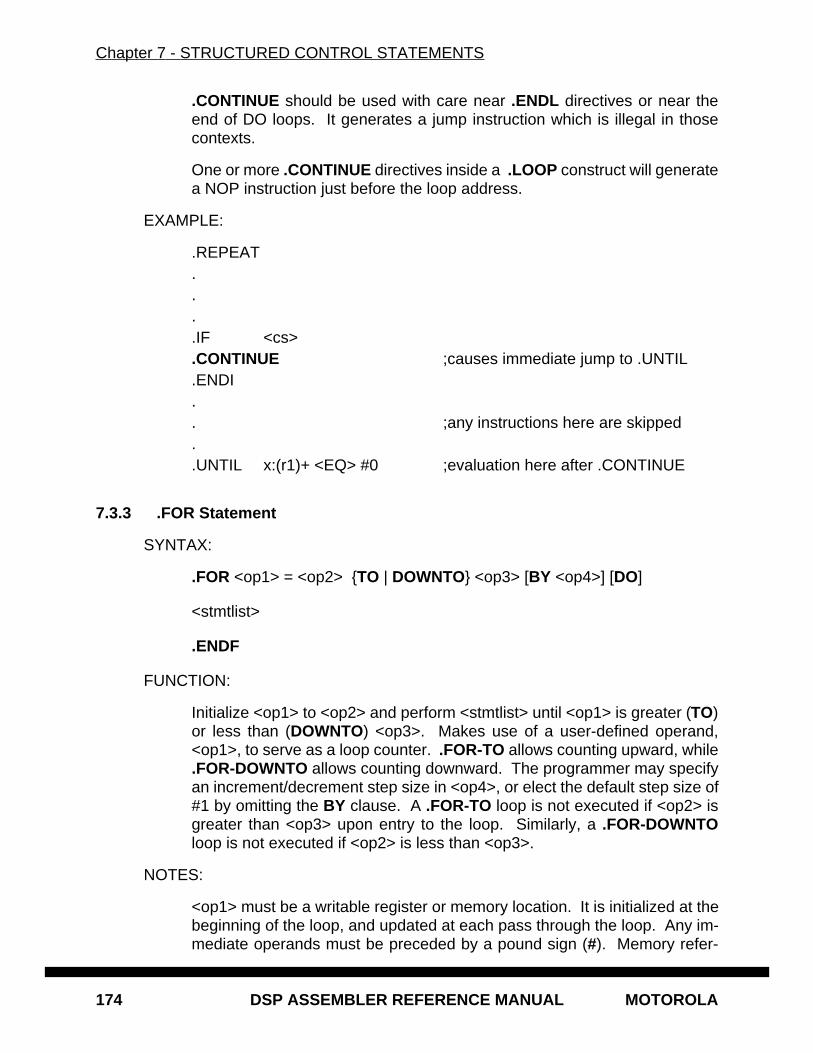
Chapter 7 - STRUCTURED CONTROL STATEMENTS
174 DSP ASSEMBLER REFERENCE MANUAL MOTOROLA
.CONTINUE should be used with care near .ENDL directives or near theend of DO loops. It generates a jump instruction which is illegal in thosecontexts.
One or more .CONTINUE directives inside a .LOOP construct will generatea NOP instruction just before the loop address.
EXAMPLE:
.REPEAT
.
.
.
.IF <cs>
.CONTINUE ;causes immediate jump to .UNTIL
.ENDI
.
. ;any instructions here are skipped
.
.UNTIL x:(r1)+ <EQ> #0 ;evaluation here after .CONTINUE
7.3.3 .FOR Statement
SYNTAX:
.FOR <op1> = <op2> {TO | DOWNTO} <op3> [BY <op4>] [DO]
<stmtlist>
.ENDF
FUNCTION:
Initialize <op1> to <op2> and perform <stmtlist> until <op1> is greater (TO)or less than (DOWNTO) <op3>. Makes use of a user-defined operand,<op1>, to serve as a loop counter. .FOR-TO allows counting upward, while.FOR-DOWNTO allows counting downward. The programmer may specifyan increment/decrement step size in <op4>, or elect the default step size of#1 by omitting the BY clause. A .FOR-TO loop is not executed if <op2> isgreater than <op3> upon entry to the loop. Similarly, a .FOR-DOWNTOloop is not executed if <op2> is less than <op3>.
NOTES:
<op1> must be a writable register or memory location. It is initialized at thebeginning of the loop, and updated at each pass through the loop. Any im-mediate operands must be preceded by a pound sign (#). Memory refer-
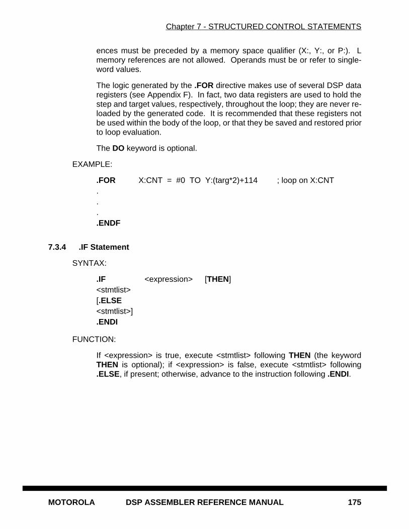
Chapter 7 - STRUCTURED CONTROL STATEMENTS
MOTOROLA DSP ASSEMBLER REFERENCE MANUAL 175
ences must be preceded by a memory space qualifier (X:, Y:, or P:). Lmemory references are not allowed. Operands must be or refer to single-word values.
The logic generated by the .FOR directive makes use of several DSP dataregisters (see Appendix F). In fact, two data registers are used to hold thestep and target values, respectively, throughout the loop; they are never re-loaded by the generated code. It is recommended that these registers notbe used within the body of the loop, or that they be saved and restored priorto loop evaluation.
The DO keyword is optional.
EXAMPLE:
.FOR X:CNT = #0 TO Y:(targ*2)+114 ; loop on X:CNT
.
.
.
.ENDF
7.3.4 .IF Statement
SYNTAX:
.IF <expression> [THEN]<stmtlist>[.ELSE<stmtlist>].ENDI
FUNCTION:
If <expression> is true, execute <stmtlist> following THEN (the keywordTHEN is optional); if <expression> is false, execute <stmtlist> following.ELSE, if present; otherwise, advance to the instruction following .ENDI.
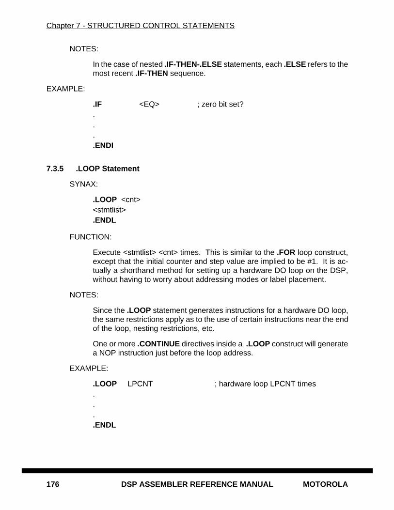
Chapter 7 - STRUCTURED CONTROL STATEMENTS
176 DSP ASSEMBLER REFERENCE MANUAL MOTOROLA
NOTES:
In the case of nested .IF-THEN-.ELSE statements, each .ELSE refers to themost recent .IF-THEN sequence.
EXAMPLE:
.IF <EQ> ; zero bit set?
.
.
.
.ENDI
7.3.5 .LOOP Statement
SYNAX:
.LOOP <cnt><stmtlist>.ENDL
FUNCTION:
Execute <stmtlist> <cnt> times. This is similar to the .FOR loop construct,except that the initial counter and step value are implied to be #1. It is ac-tually a shorthand method for setting up a hardware DO loop on the DSP,without having to worry about addressing modes or label placement.
NOTES:
Since the .LOOP statement generates instructions for a hardware DO loop,the same restrictions apply as to the use of certain instructions near the endof the loop, nesting restrictions, etc.
One or more .CONTINUE directives inside a .LOOP construct will generatea NOP instruction just before the loop address.
EXAMPLE:
.LOOP LPCNT ; hardware loop LPCNT times
.
.
.
.ENDL
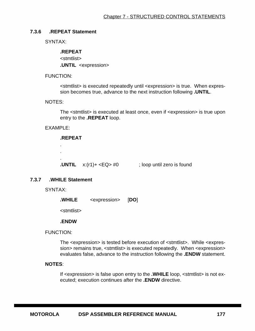
Chapter 7 - STRUCTURED CONTROL STATEMENTS
MOTOROLA DSP ASSEMBLER REFERENCE MANUAL 177
7.3.6 .REPEAT Statement
SYNTAX:
.REPEAT<stmtlist>.UNTIL <expression>
FUNCTION:
<stmtlist> is executed repeatedly until <expression> is true. When expres-sion becomes true, advance to the next instruction following .UNTIL.
NOTES:
The <stmtlist> is executed at least once, even if <expression> is true uponentry to the .REPEAT loop.
EXAMPLE:
.REPEAT
.
.
.
.UNTIL x:(r1)+ <EQ> #0 ; loop until zero is found
7.3.7 .WHILE Statement
SYNTAX:
.WHILE <expression> [DO]
<stmtlist>
.ENDW
FUNCTION:
The <expression> is tested before execution of <stmtlist>. While <expres-sion> remains true, <stmtlist> is executed repeatedly. When <expression>evaluates false, advance to the instruction following the .ENDW statement.
NOTES:
If <expression> is false upon entry to the .WHILE loop, <stmtlist> is not ex-ecuted; execution continues after the .ENDW directive.
Chapter 7 - STRUCTURED CONTROL STATEMENTS
178 DSP ASSEMBLER REFERENCE MANUAL MOTOROLA
The DO keyword is optional.
EXAMPLE:
.WHILE x:(r1)+ <GT> #0 ; loop until zero is found
.
.
.
.ENDW
7.4 SIMPLE AND COMPOUND EXPRESSIONS
Expressions are an integral part of .IF, .REPEAT, and .WHILE statements. Structuredcontrol statement expressions should not be confused with the assembler expressionsdiscussed in Chapter 3. The latter are evaluated at assembly time and will be referred tohere as "assembler expressions"; they can serve as operands in structured control state-ment expressions. The structured control statement expressions described below areevaluated at run time and will be referred to in the following discussion simply as "expres-sions".
A structured control statement expression may be simple or compound. A compound ex-pression consists of two or more simple expressions joined by either AND or OR (but notboth in a single compound expression).
7.4.1 Simple Expressions
Simple expressions are concerned with the bits of the Condition Code Register (CCR).These expressions are of two types. The first type merely tests conditions currently spec-ified by the contents of the CCR (section 7.4.1.1). The second type sets up a comparisonof two operands to set the condition codes, and afterwards tests the codes (section7.4.1.2).
7.4.1.1 Condition Code Expressions
A variety of tests (identical to those in the Jcc instruction) may be performed, based onthe CCR condition codes. The condition codes, in this case, are preset by either a user-generated instruction or a structured operand-comparison expression (section 7.4.1.2).Each test is expressed in the structured control statement by a mnemonic enclosed in an-gle brackets; the mnemonics are described in Appendix F, Condition Code Mnemonics.

Chapter 7 - STRUCTURED CONTROL STATEMENTS
MOTOROLA DSP ASSEMBLER REFERENCE MANUAL 179
When processed by the assembler, the expression generates an inverse conditional jumpto beyond the matching .ENDx/.UNTIL directive. For example:
.IF <EQ> ;zero bit set?+ bne Z_L00002 ;code generated by assembler
CLR D1 ;user code.ENDI
+ Z_L00002 ;assembler-generated label.REPEAT ;subtract until D0 < D7
+ Z_L00034 ;assembler-generated labelSUB D7,D0 ;user code.UNTIL <LT>
+ bge Z_L00034 ;code generated by assembler
7.4.1.2 Operand Comparison Expressions
Two operands may be compared in a simple expression, with subsequent transfer of con-trol based on that comparison. Such a comparison takes the form:
<op1> <cc> <op2>
where <cc> is a condition mnemonic enclosed in angle brackets (as described in section7.4.1.1), and <op1> and <op2> are register or memory references, symbols, or assemblerexpressions. When processed by the assembler, the operands are arranged such that acompare/jump sequence of the following form always results:
CMP <reg1>,<reg2>(J|B)cc <label>
where the jump conditional is the inverse of <cc>. Ordinarily <op1> is moved to the<reg1> data register and <op2> is moved to the <reg2> data register prior to the compare.This is not always the case, however: if <op1> happens to be <reg2> and <op2> is<reg1>, an intermediate register is used as a scratch register. In any event, worst casecode generation for a given operand comparison expression is generally two moves, acompare, and a conditional jump.
Jumps or branches generated by structured control statements are forced long becausethe number and address of intervening instructions between a control statement and itstermination are not known by the assembler. The programmer may circumvent this be-havior by use of the SCSJMP directive (see Chapter 6).
Any immediate operands must be preceded by a pound sign (#). Memory referencesmust be preceded by a memory space qualifier (X:, Y:, or P:). L memory references arenot allowed. Operands must be or refer to single-word values.
Chapter 7 - STRUCTURED CONTROL STATEMENTS
180 DSP ASSEMBLER REFERENCE MANUAL MOTOROLA
Note that values in the <reg1> and <reg2> data registers are not saved before expressionevaluation. This means that any user data in those registers will be overwritten each timethe expression is evaluated at runtime. The programmer should take care either to saveneeded contents of the registers, reassign data registers using the SCSREG directive, ornot use them at all in the body of the particular structured construct being executed. Thedata registers used by the structured control statements are listed in Appendix F.
7.4.2 Compound Expressions
A compound expression consists of two or more simple expressions (section 7.4.1) joinedby a logical operator (AND or OR). The boolean value of the compound expression is de-termined by the boolean values of the simple expressions and the nature of the logicaloperator. Note that the result of mixing logical operators in a compound expression is un-defined:
.IF X1 <GT> B AND <LS> AND R1 <NE> R2 ;this is OK
.IF X1 <LE> B AND <LC> OR R5 <GT> R6 ;undefined
The simple expressions are evaluated left to right. Note that this means the result of onesimple expression could have an impact on the result of subsequent simple expressions,because of the condition code settings stemming from the assembler-generated com-pare.
If the compound expression is an AND expression and one of the simple expressions isfound to be false, any further simple expressions are not evaluated. Likewise, if the com-pound expression is an OR expression and one of the simple expressions is found to betrue, any further simple expressions are not evaluated. In these cases, the compound ex-pression is either false or true, respectively, and the condition codes reflect the result ofthe last simple expression evaluated.
7.5 STATEMENT FORMATTING
The format of structured control statements differs somewhat from normal assembler us-age. Whereas a standard assembler line is split into fields separated by blanks or tabs,with no white space inside the fields, structured control statement formats vary dependingon the statement being analyzed. In general, all structured control directives are placedin the opcode field (with an optional label in the label field) and white space separates alldistinct fields in the statement. Any structured control statement may be followed by acomment on the same logical line.
7.5.1 Expression Formatting
Given an expression of the form:
<op1> <LT> <op2> OR <op3> <GE> <op4>
Chapter 7 - STRUCTURED CONTROL STATEMENTS
MOTOROLA DSP ASSEMBLER REFERENCE MANUAL 181
there must be white space (blank, tab) between all operands and their associated opera-tors, including boolean operators in compound expressions. Moreover, there must bewhite space between the structured control directive and the expression, and between theexpression and any optional directive modifier (THEN, DO). An assembler expression(Chapter 3) used as an operand in a structured control statement expression must nothave white space in it, since it is parsed by the standard assembler evaluation routines:
.IF #@CVI(@SQT(4.0)) <GT> #2 ; no white space in first operand
7.5.2 .FOR/.LOOP Formatting
The .FOR and .LOOP directives represent special cases. The .FOR structured controlstatement consists of several fields:
.FOR <op1> = <op2> TO <op3> BY <op4> DO
There must be white space between all operands and other syntactic entities such as =,TO, BY, and DO. As with expression formatting, an assembler expression used as anoperand must not have white space in it:
.FOR X:CNT = #0 TO Y:(targ*2)+1 BY #@CVI(@POW(2.0,@CVF(R)))
In the example above, the .FOR loop operands represented as assembler expressions(symbol, function) do not have embedded white space, whereas the loop operands arealways separated from structured control statement keywords by white space.
The count field of a .LOOP statement must be separated from the .LOOP directive bywhite space. The count itself may be any arbitrary assembler expression, and thereforemust not contain embedded blanks.
7.5.3 Assembly Listing Format
Structured control statements begin with the directive in the opcode field; any optional la-bel is output in the label field. The rest of the statement is left as is in the operand field,except for any trailing comment; the X and Y data movement fields are ignored. Com-ments following the statement are output in the comment field (unless the unreportedcomment delimiter is used; see Chapter 6).
Statements are expanded using the macro facilities of the assembler. Thus the generatedcode can be sent to the listing by specifying the MEX assembler option, either via the OPTdirective (Chapter 6) or the -O command line option (Chapter 1).
7.6 EFFECTS ON THE PROGRAMMER’S ENVIRONMENT
During assembly, global labels beginning with "Z_L" are generated. They are stored in thesymbol table and should not be duplicated in user-defined labels. Because these non-lo-cal labels ordinarily are not visible to the programmer there can be problems when local
Chapter 7 - STRUCTURED CONTROL STATEMENTS
182 DSP ASSEMBLER REFERENCE MANUAL MOTOROLA
(underscore) labels are interspersed among structured control statements. The SCL op-tion (see the OPT directive, Chapter 6) causes the assembler to maintain the current locallabel scope when a structured control statement label is encountered.
In the .FOR loop, <op1> is a user-defined symbol. When exiting the loop, the memory/register assigned to this symbol contains the value which caused the exit from the loop.
A compare instruction is produced by the assembler whenever two operands are testedin a structured statement. At runtime, these assembler-generated instructions set thecondition codes of the CCR (in the case of a loop, the condition codes are set repeatedly).Any user-written code either within or following a structured statement that referencesCCR directly (move) or indirectly (conditional jump/transfer) should be attentive to the ef-fect of these instructions.
Jumps or branches generated by structured control statements are forced long becausethe number and address of intervening instructions between a control statement and itstermination are not known by the assembler. The programmer may circumvent this be-havior by use of the SCSJMP directive (see Chapter 6).
In all structured control statements except those using only a single condition code ex-pression, registers are used to set up the required counters and comparands. In somecases, these registers are effectively reserved; the .FOR loop uses two data registers tohold the step and target values, respectively, and performs no save/restore operations onthese registers. The assembler, in fact, does no save/restore processing in any structuredcontrol operation; it simply moves the operands into appropriate registers to execute thecompare. See Appendix F for a list of registers used by the assembler in support of struc-tured control statements on a particular processor. The SCSREG directive (Chapter 6)may be used to reassign structured control statement registers. The MEX assembler op-tion (see the OPT directive, Chapter 6) may be used to send the assembler-generatedcode to the listing file for examination of possible register use conflicts.
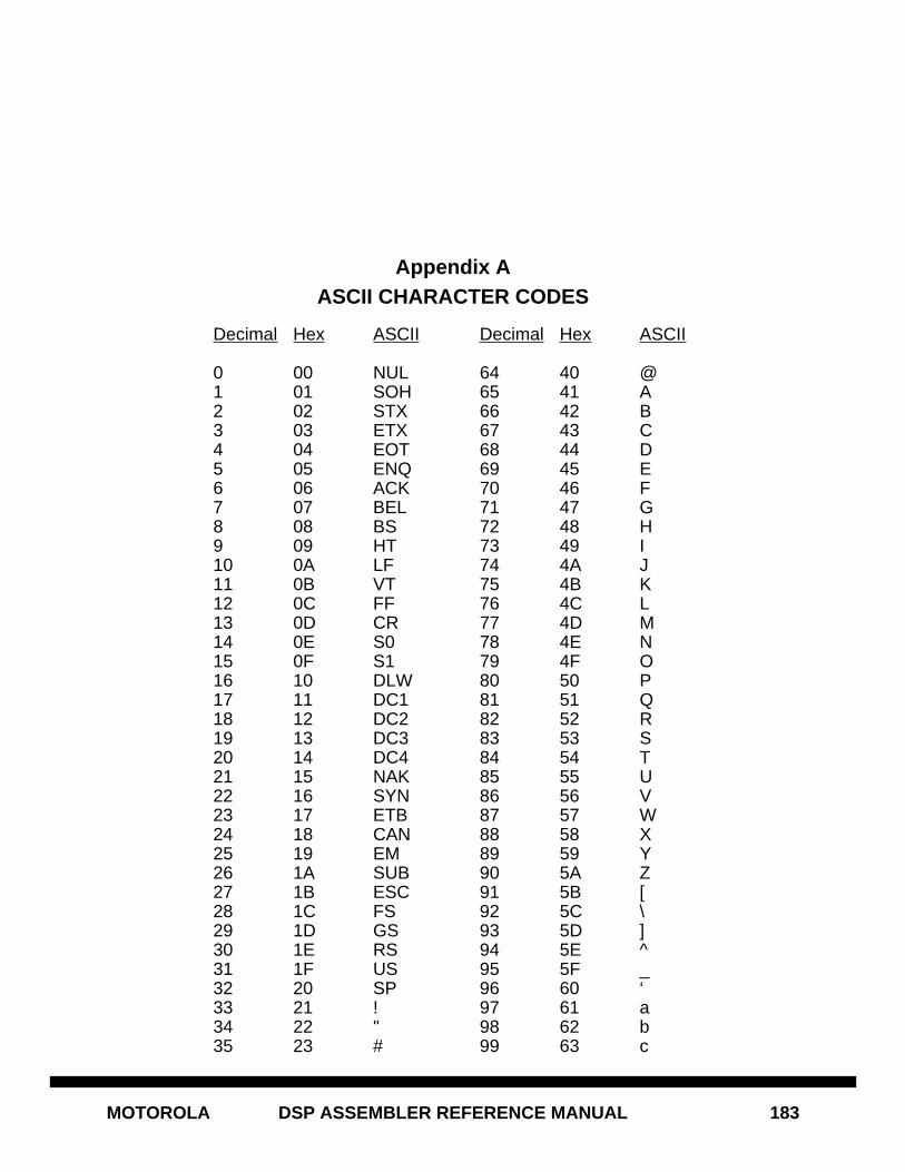
MOTOROLA DSP ASSEMBLER REFERENCE MANUAL 183
Appendix AASCII CHARACTER CODES
Decimal Hex ASCII Decimal Hex ASCII
0 00 NUL 64 40 @1 01 SOH 65 41 A2 02 STX 66 42 B3 03 ETX 67 43 C4 04 EOT 68 44 D5 05 ENQ 69 45 E6 06 ACK 70 46 F7 07 BEL 71 47 G8 08 BS 72 48 H9 09 HT 73 49 I10 0A LF 74 4A J11 0B VT 75 4B K12 0C FF 76 4C L13 0D CR 77 4D M14 0E S0 78 4E N15 0F S1 79 4F O16 10 DLW 80 50 P17 11 DC1 81 51 Q18 12 DC2 82 52 R19 13 DC3 83 53 S20 14 DC4 84 54 T21 15 NAK 85 55 U22 16 SYN 86 56 V23 17 ETB 87 57 W24 18 CAN 88 58 X25 19 EM 89 59 Y26 1A SUB 90 5A Z27 1B ESC 91 5B [28 1C FS 92 5C \29 1D GS 93 5D ]30 1E RS 94 5E ^31 1F US 95 5F _32 20 SP 96 60 ‘33 21 ! 97 61 a34 22 " 98 62 b35 23 # 99 63 c
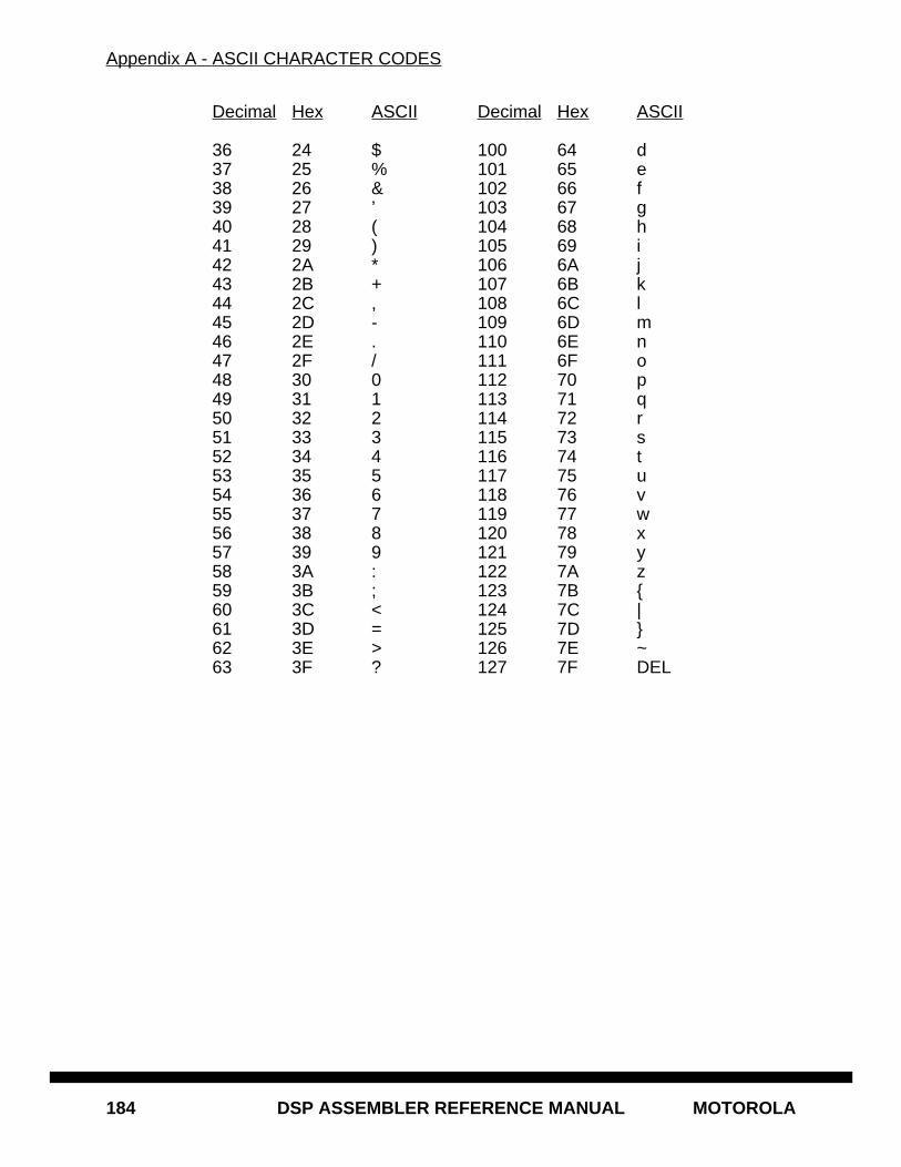
Appendix A - ASCII CHARACTER CODES
184 DSP ASSEMBLER REFERENCE MANUAL MOTOROLA
Decimal Hex ASCII Decimal Hex ASCII
36 24 $ 100 64 d37 25 % 101 65 e38 26 & 102 66 f39 27 ’ 103 67 g40 28 ( 104 68 h41 29 ) 105 69 i42 2A * 106 6A j43 2B + 107 6B k44 2C , 108 6C l45 2D - 109 6D m46 2E . 110 6E n47 2F / 111 6F o48 30 0 112 70 p49 31 1 113 71 q50 32 2 114 72 r51 33 3 115 73 s52 34 4 116 74 t53 35 5 117 75 u54 36 6 118 76 v55 37 7 119 77 w56 38 8 120 78 x57 39 9 121 79 y58 3A : 122 7A z59 3B ; 123 7B {60 3C < 124 7C |61 3D = 125 7D }62 3E > 126 7E ~63 3F ? 127 7F DEL
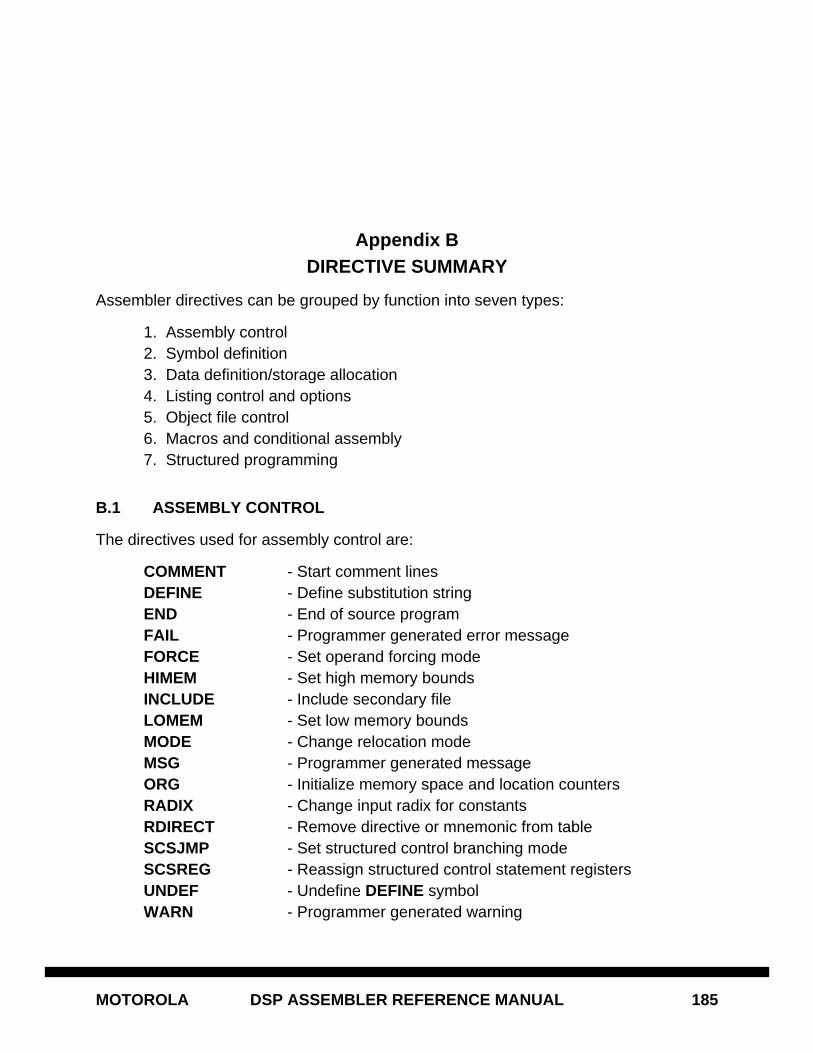
MOTOROLA DSP ASSEMBLER REFERENCE MANUAL 185
Appendix BDIRECTIVE SUMMARY
Assembler directives can be grouped by function into seven types:
1. Assembly control2. Symbol definition3. Data definition/storage allocation4. Listing control and options5. Object file control6. Macros and conditional assembly7. Structured programming
B.1 ASSEMBLY CONTROL
The directives used for assembly control are:
COMMENT - Start comment linesDEFINE - Define substitution stringEND - End of source programFAIL - Programmer generated error messageFORCE - Set operand forcing modeHIMEM - Set high memory boundsINCLUDE - Include secondary fileLOMEM - Set low memory boundsMODE - Change relocation modeMSG - Programmer generated messageORG - Initialize memory space and location countersRADIX - Change input radix for constantsRDIRECT - Remove directive or mnemonic from tableSCSJMP - Set structured control branching modeSCSREG - Reassign structured control statement registersUNDEF - Undefine DEFINE symbolWARN - Programmer generated warning
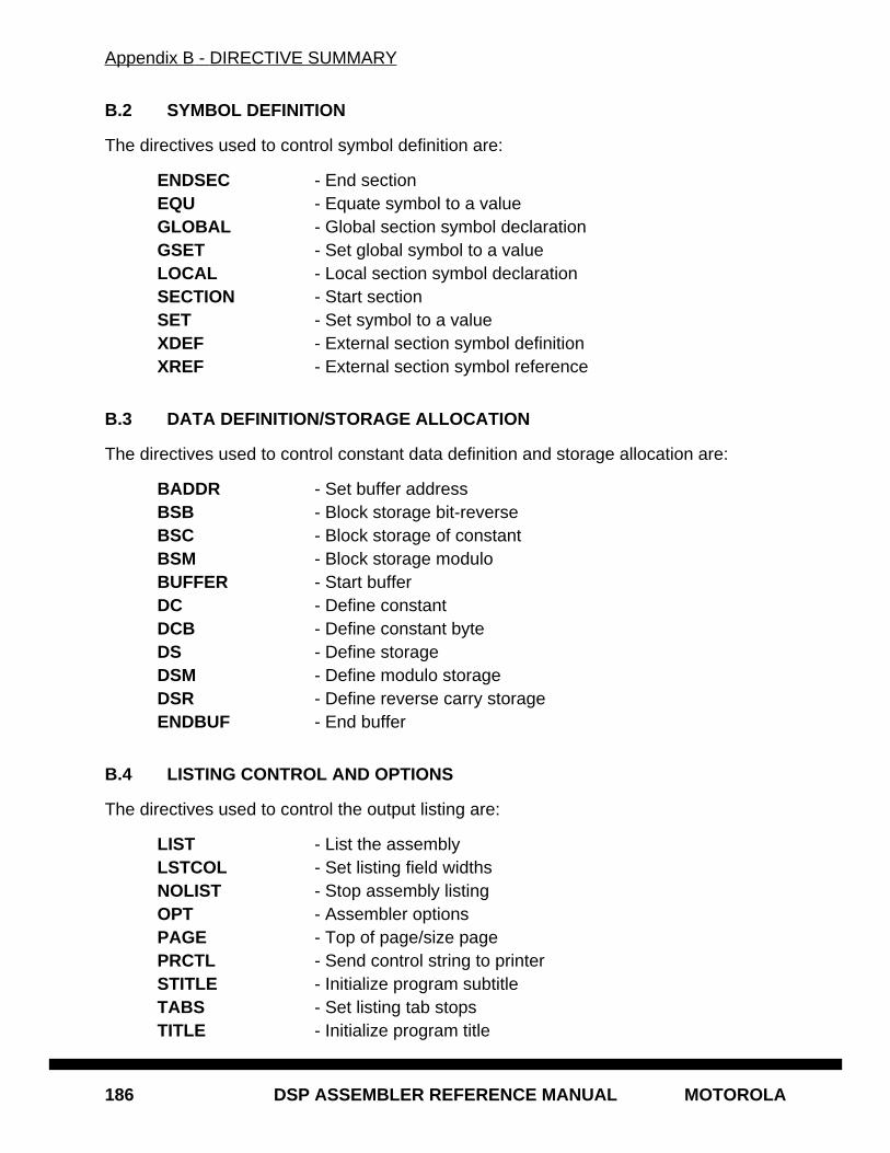
Appendix B - DIRECTIVE SUMMARY
186 DSP ASSEMBLER REFERENCE MANUAL MOTOROLA
B.2 SYMBOL DEFINITION
The directives used to control symbol definition are:
ENDSEC - End sectionEQU - Equate symbol to a valueGLOBAL - Global section symbol declarationGSET - Set global symbol to a valueLOCAL - Local section symbol declarationSECTION - Start sectionSET - Set symbol to a valueXDEF - External section symbol definitionXREF - External section symbol reference
B.3 DATA DEFINITION/STORAGE ALLOCATION
The directives used to control constant data definition and storage allocation are:
BADDR - Set buffer addressBSB - Block storage bit-reverseBSC - Block storage of constantBSM - Block storage moduloBUFFER - Start bufferDC - Define constantDCB - Define constant byteDS - Define storageDSM - Define modulo storageDSR - Define reverse carry storageENDBUF - End buffer
B.4 LISTING CONTROL AND OPTIONS
The directives used to control the output listing are:
LIST - List the assemblyLSTCOL - Set listing field widthsNOLIST - Stop assembly listingOPT - Assembler optionsPAGE - Top of page/size pagePRCTL - Send control string to printerSTITLE - Initialize program subtitleTABS - Set listing tab stopsTITLE - Initialize program title
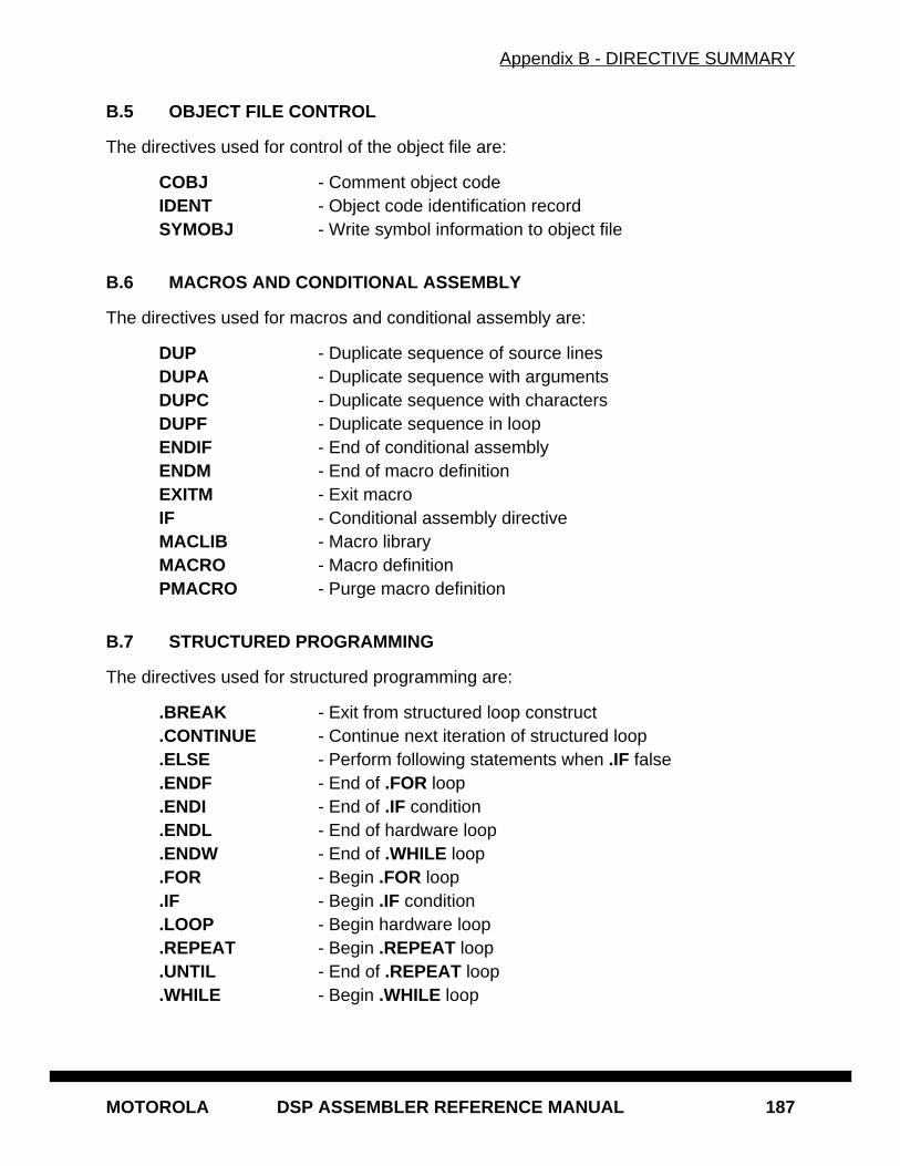
Appendix B - DIRECTIVE SUMMARY
MOTOROLA DSP ASSEMBLER REFERENCE MANUAL 187
B.5 OBJECT FILE CONTROL
The directives used for control of the object file are:
COBJ - Comment object codeIDENT - Object code identification recordSYMOBJ - Write symbol information to object file
B.6 MACROS AND CONDITIONAL ASSEMBLY
The directives used for macros and conditional assembly are:
DUP - Duplicate sequence of source linesDUPA - Duplicate sequence with argumentsDUPC - Duplicate sequence with charactersDUPF - Duplicate sequence in loopENDIF - End of conditional assemblyENDM - End of macro definitionEXITM - Exit macroIF - Conditional assembly directiveMACLIB - Macro libraryMACRO - Macro definitionPMACRO - Purge macro definition
B.7 STRUCTURED PROGRAMMING
The directives used for structured programming are:
.BREAK - Exit from structured loop construct
.CONTINUE - Continue next iteration of structured loop
.ELSE - Perform following statements when .IF false
.ENDF - End of .FOR loop
.ENDI - End of .IF condition
.ENDL - End of hardware loop
.ENDW - End of .WHILE loop
.FOR - Begin .FOR loop
.IF - Begin .IF condition
.LOOP - Begin hardware loop
.REPEAT - Begin .REPEAT loop
.UNTIL - End of .REPEAT loop
.WHILE - Begin .WHILE loop
Appendix B - DIRECTIVE SUMMARY
188 DSP ASSEMBLER REFERENCE MANUAL MOTOROLA
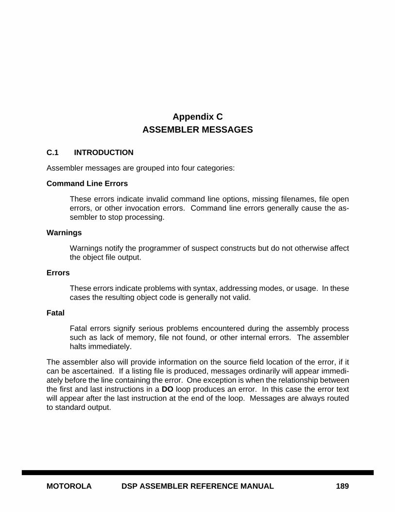
MOTOROLA DSP ASSEMBLER REFERENCE MANUAL 189
Appendix CASSEMBLER MESSAGES
C.1 INTRODUCTION
Assembler messages are grouped into four categories:
Command Line Errors
These errors indicate invalid command line options, missing filenames, file openerrors, or other invocation errors. Command line errors generally cause the as-sembler to stop processing.
Warnings
Warnings notify the programmer of suspect constructs but do not otherwise affectthe object file output.
Errors
These errors indicate problems with syntax, addressing modes, or usage. In thesecases the resulting object code is generally not valid.
Fatal
Fatal errors signify serious problems encountered during the assembly processsuch as lack of memory, file not found, or other internal errors. The assemblerhalts immediately.
The assembler also will provide information on the source field location of the error, if itcan be ascertained. If a listing file is produced, messages ordinarily will appear immedi-ately before the line containing the error. One exception is when the relationship betweenthe first and last instructions in a DO loop produces an error. In this case the error textwill appear after the last instruction at the end of the loop. Messages are always routedto standard output.
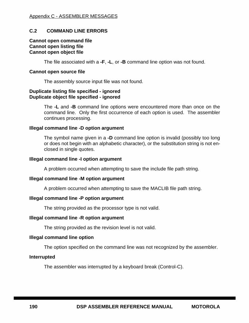
Appendix C - ASSEMBLER MESSAGES
190 DSP ASSEMBLER REFERENCE MANUAL MOTOROLA
C.2 COMMAND LINE ERRORS
Cannot open command fileCannot open listing fileCannot open object file
The file associated with a -F, -L, or -B command line option was not found.
Cannot open source file
The assembly source input file was not found.
Duplicate listing file specified - ignoredDuplicate object file specified - ignored
The -L and -B command line options were encountered more than once on thecommand line. Only the first occurrence of each option is used. The assemblercontinues processing.
Illegal command line -D option argument
The symbol name given in a -D command line option is invalid (possibly too longor does not begin with an alphabetic character), or the substitution string is not en-closed in single quotes.
Illegal command line -I option argument
A problem occurred when attempting to save the include file path string.
Illegal command line -M option argument
A problem occurred when attempting to save the MACLIB file path string.
Illegal command line -P option argument
The string provided as the processor type is not valid.
Illegal command line -R option argument
The string provided as the revision level is not valid.
Illegal command line option
The option specified on the command line was not recognized by the assembler.
Interrupted
The assembler was interrupted by a keyboard break (Control-C).
Appendix C - ASSEMBLER MESSAGES
MOTOROLA DSP ASSEMBLER REFERENCE MANUAL 191
LDB option with no listing file specified; using source file
The LDB option was given on the command line without a corresponding -L to gen-erate a listing file. If a listing file is not produced, debugging packages cannot useit for source tracking. Therefore the assembler uses the default assembly languagefile as input for source tracking.
Missing command line option argument
The expected arguments following a command line option specifier were missing.
Missing source filename
There must be at least one source filename specified on the command line.
Source file name same as listing file nameSource file name same as object file name
One of the source files appeared to the assembler to have the same name as thespecified listing or object file. The assembler aborts rather than potentially writingover a source input file.
Appendix C - ASSEMBLER MESSAGES
192 DSP ASSEMBLER REFERENCE MANUAL MOTOROLA
C.3 WARNINGS
Absolute address involves incompatible memory spaces
The memory space attribute is regarded by the assembler as a type, in the samesense that high level languages use type for variables. Symbols may have memoryspace attributes of X, Y, L, P(rogram), E(MI), or N(one); only N is fully compatiblewith all other attributes. In this case, an operand was evaluated with a differentmemory space attribute than that specified in the instruction.
Absolute address too large to use I/O short - long substituted
The absolute address is not within the range specifying an I/O short address, eventhough the I/O short forcing operator has been used. The assembler substituteslong absolute addressing.
Absolute address too large to use short - long substituted
The absolute address value being forced short will not fit in the storage allocatedfor a short address. The assembler substitutes long absolute addressing.
Absolute address too small to use I/O short - long substituted
The absolute address is not within the range specifying an I/O short address, eventhough the I/O short forcing operator has been used. The assembler substituteslong absolute addressing.
Address involves incompatible memory spaces
The memory space attribute is regarded by the assembler as a type, in the samesense that high level languages use type for variables. Symbols may have memoryspace attributes of X, Y, L, P(rogram), E(MI), or N(one); only N is fully compatiblewith all other attributes. In this case, an operand was evaluated with a differentmemory space attribute than that specified in the instruction.
Cannot force short addressing for source and destination
In a MOVEP or MOVES instruction an attempt was made to force both operandsto short or I/O short. The second operand defaults to long.
Cannot force short immediate with this parallel move
The immediate operand in the X field of a parallel X memory and register movecannot be forced short. The mode is changed to long immediate.
Contents of assigned register in previous instruction not available -generating NOP instruction
Due to pipelining, if an address register (Rn or Nn) is changed in the previous in-struction, the new contents are not available for use as a pointer until the next in-struction. If the RP option is in effect (see the OPT directive, Chapter 6) the

Appendix C - ASSEMBLER MESSAGES
MOTOROLA DSP ASSEMBLER REFERENCE MANUAL 193
assembler produces this warning and generates a NOP prior to the offending in-struction.
Debug directives ignored - use command line debug option
A source-level debug directive was encountered but the assembler command line-G option was not given.
Destination operand assumed I/O short
Neither operand in a MOVEP instruction is explicitly declared I/O short; however,the source operand does not qualify, so the destination operand is assumed to bethe I/O short operand.
Directive not allowed in command line absolute mode
The MODE directive is ignored when the assembler command line -A option is ac-tive.
Duplicate listing file specified - ignoredDuplicate object file specified - ignored
The -B or -L command line options were given more than once.
ENDDO instruction not inside DO loop
An ENDDO instruction was found outside the scope of an active DO loop.
Explicit bottom margin ignored with page length of zeroExplicit top margin ignored with page length of zero
The top or bottom margin parameters to a PAGE directive are ignored because thepage length parameter was zero.
Expression involves incompatible memory spaces
The memory space attribute is regarded by the assembler as a type, in the samesense that high level languages use type for variables. Symbols may have memoryspace attributes of X, Y, L, P(rogram), E(MI), or N(one); only N is fully compatiblewith all other attributes. In this case, two operands were evaluated with differentmemory space attributes, neither of which was N.
Expression value outside fractional domain
The expected fractional value was not within the range -1.0 <= m < 1.
Extra dimensions ignored
A source-level debug .DIM directive contained more than four arguments specify-ing the dimensions of an array.
Appendix C - ASSEMBLER MESSAGES
194 DSP ASSEMBLER REFERENCE MANUAL MOTOROLA
FMPY suffix ignored - using secondary opcode suffix
The single or extended precision suffix on a dual-opcode instruction has been ig-nored. The precision is taken from the suffix on the secondary opcode.
Immediate value too large to use short - long substituted
An immediate data value being forced short is too large to fit in the space allocatedfor a short immediate value. The assembler substitutes long immediate address-ing.
Improper nesting of DO loops
The end address of a subordinate (nested) DO loop is greater than or equal to theend address of the loop enclosing it. The end address of a nested DO instructionmust be less than the end address of the enclosing loop.
Instruction cannot appear in interrupt vector locations
Some instructions cannot be used reliably as interrupt code. These instructions in-clude RTI, RTS, DO, and ENDDO.
Instruction does not allow data movement specified - using MOVE encodingInstruction does not allow data movement specified - using MOVEP encodingInstruction does not allow data movement specified - using MOVES encoding
An inappropriate MOVE-type instruction was written given the type of the oper-ands. The assembler substitutes a valid encoding for the operands in question.
Invalid destination register for this instruction - using TFR3 encoding
The destination register for a TFR2 instruction was not either X or Y.
Invalid interrupt vector address - using SWI address
Currently only the SWI address is supported by the TRAPcc instruction.
I/O short absolute address cannot be forced
I/O short absolute addressing is not valid for this operation. An appropriate ad-dressing mode (long absolute, short jump, short absolute) is substituted.
I/O short absolute address cannot be forced - long substituted
I/O short absolute addressing is not valid for this operation. The assembler substi-tutes long absolute addressing.
I/O short address cannot be forced
I/O short addressing is not valid for this operation. An appropriate addressingmode (long, short, short jump) is substituted.
Appendix C - ASSEMBLER MESSAGES
MOTOROLA DSP ASSEMBLER REFERENCE MANUAL 195
I/O short address cannot be forced - long substituted
I/O short addressing is not valid for this operation. The assembler substitutes longaddressing.
Label field ignored
The assembler directive does not allow a label, so the assembler will not store thelabel value in the symbol table.
Load location counter overflowLoad location counter underflow
The load location counter exceeded its maximum or minimum value. The assem-bler wraps the counter value around and continues.
Load origin involves incompatible memory spaces
The memory space attribute is regarded by the assembler as a type, in the samesense that high level languages use type for variables. Symbols may have memoryspace attributes of X, Y, L, P(rogram), E(MI), or N(one); only N is fully compatiblewith all other attributes. In this case, an operand was evaluated with a differentmemory space attribute than that specified in the directive.
Load reserved address space violation
The load location counter has incremented into a reserved area of data addressspace.
Long absolute address cannot be forced
Long absolute addressing is not valid for this operation. An appropriate addressingmode (I/O absolute, short jump, short absolute) is substituted.
Long absolute address cannot be forced - substituting I/O short addressing
Long absolute addressing is not valid for this operation. The assembler substitutesI/O short addressing.
Long absolute address cannot be forced - substituting short addressing
Long absolute addressing is not valid for this operation. The assembler substitutesshort absolute addressing.
Long immediate cannot be forced
Long immediate data is not valid for this operation. An appropriate size for the tar-get DSP is substituted.
Appendix C - ASSEMBLER MESSAGES
196 DSP ASSEMBLER REFERENCE MANUAL MOTOROLA
Long PC-relative address cannot be forced
Long PC-relative addressing is not valid for this operation. An appropriate ad-dressing mode (short PC-relative) is substituted.
Macro expansion not active
A macro must have been called prior to using the @ARG() or @CNT() functions(see Chapter 3).
Macro name is the same as existing assembler directiveMacro name is the same as existing assembler mnemonic
The name of the macro being defined conflicts with the name of an assembler di-rective or mnemonic. Either use a different macro name or use the RDIRECT di-rective to remove the directive or mnemonic name from the assembler lookuptables.
No control registers accessed - using MOVE encoding
A MOVEC-type instruction was given but no control registers were used as oper-ands. The assembler substitutes a valid encoding for the operands in question.
No looping construct found - .BREAK ignoredNo looping construct found - .CONTINUE ignored
A .BREAK or .CONTINUE structure control statement was encountered outside ofany active looping construct (.FOR, .LOOP, .REPEAT, .WHILE).
Number of macro expansion arguments is greater than definitionNumber of macro expansion arguments is less than definition
A discrepancy exists between the number of arguments specified in a macro defi-nition and the number of arguments provided in the macro call.
Options for both debug and strip specified - strip ignored
Both the -G and -Z options were given on the command line. The -G option takesprecedence.
P space not accessed - using MOVE encoding
A MOVEP-type instruction was given but a P memory reference was not used asan operand. The assembler substitutes a valid encoding for the operands in ques-tion.
Page directive with no arguments ignored with page length of zero
A PAGE directive with no arguments, which ordinarily produces a form feed in thelisting output, is ignored because a previous PAGE directive specified a pagelength of zero.
Appendix C - ASSEMBLER MESSAGES
MOTOROLA DSP ASSEMBLER REFERENCE MANUAL 197
PC-relative address involves incompatible memory spaces
The memory space attribute is regarded by the assembler as a type, in the samesense that high level languages use type for variables. Symbols may have memoryspace attributes of X, Y, L, P(rogram), E(MI), or N(one); only N is fully compatiblewith all other attributes. In this case, an operand was evaluated with a differentmemory space attribute than that specified in the instruction.
PC-relative address too large to use short - long substituted
The PC-relative offset is not within the range specifying a short PC-relative offset,even though the short forcing operator has been used. The assembler substituteslong PC-relative addressing.
Possible duplicate destination register
In the DSP96000 assembly language there is potential ambiguity in the specifica-tion of registers for some types of DALU instructions and parallel moves. The as-sembler detects the ambiguity and warns if a duplicate register write is possible.
Post-update operation will not occur on destination register
If the source operand in a MOVE operation specifies a post-update addressingmode and the destination register is the same as the source operand register thenthe post-update operation will not take place.
PRCTL directive ignored - no explicit listing file
The PRCTL directive takes effect only if the -L option is used on the command lineto explicitly specify a listing file.
Redefinition of symbol
A symbol used in a DEFINE directive has been redefined without an interveningUNDEF directive. The assembler discards the previous definition and replaces itwith the new definition.
Rounding not available with LMS move - using MAC/MPY encoding
A MACR or MPYR instruction was specified in conjunction with LMS move syntax.
Runtime location counter overflowRuntime location counter underflow
The runtime location counter exceeded its maximum or minimum value. The as-sembler wraps the counter value around and continues.
Runtime origin involves incompatible memory spaces
The memory space attribute is regarded by the assembler as a type, in the samesense that high level languages use type for variables. Symbols may have memory
Appendix C - ASSEMBLER MESSAGES
198 DSP ASSEMBLER REFERENCE MANUAL MOTOROLA
space attributes of X, Y, L, P(rogram), E(MI), or N(one); only N is fully compatiblewith all other attributes. In this case, an operand was evaluated with a differentmemory space attribute than that specified in the directive.
Runtime reserved address space violation
The runtime location counter has incremented into a reserved area of data addressspace.
Short absolute address cannot be forced
Short absolute addressing is not valid for this operation. An appropriate addressingmode (long absolute) is substituted.
Short absolute address cannot be forced - long substituted
Short absolute addressing is not valid for this operation. The assembler substituteslong absolute addressing.
Short immediate cannot be forced
Short immediate data is not valid for this operation. An appropriate size is substi-tuted.
Short PC-relative address cannot be forced
Short PC-relative addressing is not valid for this operation. An appropriate ad-dressing mode (long PC-relative) is substituted.
Signed operand must come first in signed/unsigned combinations
In a MPYSU, MACSU, or DMACSU instruction, the signed operand must comefirst in the operand ordering.
Source operand assumed I/O short
Neither operand in a MOVEP instruction is explicitly declared I/O short; however,the destination operand does not qualify, so the source operand is assumed to bethe I/O short operand.
Storage block size not a power of 2
The expression in a DSR directive did not evaluate to a power of 2. Since the DSRdirective is generally used to allocate FFT buffers for reverse carry operations, thesize of the buffer may be in error.
String truncated in expression evaluation
Only the first four characters of a string constant are used during expression eval-uation except for arguments to the DC directive (see Chapter 6).
Appendix C - ASSEMBLER MESSAGES
MOTOROLA DSP ASSEMBLER REFERENCE MANUAL 199
Strip not valid in relocatable mode - ignored
The -Z option is valid only when the -A option is also given.
Unresolved external reference
Ordinarily the assembler does not flag unresolved references in relative mode, as-suming they will be resolved at link time. If the UR option is specified, the assem-bler will generate this warning if any symbols are undefined during the secondpass.
Appendix C - ASSEMBLER MESSAGES
200 DSP ASSEMBLER REFERENCE MANUAL MOTOROLA
C.4 ERRORS
Absolute address contains forward reference - force short or I/O short address
The assembler attempted a default to short addressing which failed. Either the ab-solute address is too large or it needs to be forced I/O short.
Absolute address must be either short or I/O short
The absolute address is too large for a short address and outside the range of validI/O short addresses.
Absolute address too large to use I/O shortAbsolute address too small to use I/O short
The absolute address being forced short is outside the range of valid I/O short ad-dresses. This usually means that the I/O short address has not been ones extend-ed.
Absolute address too large to use short
The absolute address value is too large to be forced short.
Absolute addressing mode not allowed
Absolute operands are not allowed with some instructions, in particular parallel XYdata memory moves.
Address mode syntax error - expected ')'Address mode syntax error - expected '+'Address mode syntax error - expected '+' or '-'Address mode syntax error - expected commaAddress mode syntax error - expected comma or end of fieldAddress mode syntax error - expected offset registerAddress mode syntax error - extra charactersAddress mode syntax error - probably missing ')'
A syntax error was detected when scanning the source line operand and/or X andY data fields. These errors may indicate omission of a source operand, insufficientwhite space between fields, or improper specification of address register indirectaddressing modes.
Argument outside function domain
An argument to one of the transcendental built-in functions was inappropriate.
Arithmetic exception
An internal floating point exception occurred while evaluating an expression. Theresult of the evaluation is probably not valid.
Appendix C - ASSEMBLER MESSAGES
MOTOROLA DSP ASSEMBLER REFERENCE MANUAL 201
Assembler directive or mnemonic not found
An argument to the RDIRECT directive was not a recognized assembler directiveor mnemonic.
Base argument larger than machine word size
The base parameter of a @FLD() function has a value larger than can fit in the tar-get machine word.
Binary constant expected
A character other than ASCII '0' or '1' either followed the binary constant delimiter(%) or appeared in an expression where a binary value was expected by default.
Bit mask cannot span more than eight bits
If the first operand of a BFxxx -type instruction was shifted one bit to the right untilthe low-order bit was a 1, the resulting value must not exceed $FF hexadecimal.
Cannot conditionally repeat write to memory
A move to memory cannot be preceded by a REPcc -type instruction.
Cannot nest section inside itself
A section of a given name may not have another SECTION directive with the samename declared inside it.
Cannot nest symbol definitions
A source-level debug .DEF directive was encountered inside another .DEF-.EN-DEF pair.
Cannot open include file
The specified INCLUDE file cannot be found, or the operating system limit on openfiles has been exceeded.
Cannot repeat this instructionCannot repeat two-word instruction
The REP instruction cannot be used to repeat two-word instructions or instructionsthat change program flow. Instructions that cannot be repeated include DO, Jcc ,JCLR , JMP, JSET, JScc , JSCLR , JSR, JSSET, REP, RTI, RTS, and SWI.
CONST option must be used before any label
This option, which prevents EQU symbols from being exported to the object file,must be given before any label is encountered in the source file.

Appendix C - ASSEMBLER MESSAGES
202 DSP ASSEMBLER REFERENCE MANUAL MOTOROLA
Contents of assigned register in previous instruction not available
Due to pipelining, if an address register (Rn or Nn) is changed in the previous in-struction, the new contents are not available for use as a pointer until the next in-struction.
Count must be an integer value
The argument to a DUP directive did not evaluate as an integer expression.
CRE option must be used before any label
The CRE option must be activated before any labels are encountered so that theassembler can append cross-reference data to all applicable symbol table entries.
Data allocation exceeds buffer size
Data allocated between a BUFFER-ENDBUF sequence exceeded the size speci-fied in the BUFFER directive.
Decimal constant expected
A character other than ASCII '0' through '9' either followed the decimal constant de-limiter (‘) or appeared in an expression where a decimal value was expected by de-fault.
DEFINE symbol must be a global symbol name
A local label (a symbol beginning with the underscore character) may not be usedas a DEFINE directive symbol.
Directive not allowed in EMI memory
Any kind of buffer directive is disallowed when the runtime memory space is E(MI).
Displacement address mode not allowed
Long displacement addressing is not allowed with some instructions, in particularparallel XY data memory moves.
Divide by zero
The expression evaluator detected a divide by zero.
DO loop address must be in current section
The loop address of a DO loop cannot fall outside the bounds of its enclosing sec-tion. This is particularly important in relative mode as the loop address is calculat-ed based on the starting address of the section.
Appendix C - ASSEMBLER MESSAGES
MOTOROLA DSP ASSEMBLER REFERENCE MANUAL 203
Dummy argument not found
The dummy argument name given as an argument to the @ARG() function wasnot found in the macro dummy argument list.
Duplicate destination register not allowed
If the opcode-operand portion of an instruction specifies a destination register, thesame register or portion of that register may not be specified as a destination in theparallel data bus move operation.
Duplicate source and destination register not allowed
If the opcode-operand portion of an instruction specifies a source register, thesame register or portion of that register may not be specified as a destination in theparallel data bus move operation.
Either source or destination memory space must be X or Y
One of the operands in a MOVEP instruction must reference a location in X or Ymemory.
ELSE without associated IF directive
An ELSE directive was encountered without a preceding IF conditional assemblydirective.
.ELSE without associated .IF directive
An .ELSE directive was encountered before a matching .IF conditional structuredcontrol statement.
Empty bit mask field
The first operand of a BFxxx -type instruction was zero.
End of structure or union without matching definition
A source-level debug end-of-structure symbol declaration was recognized withouta preceding structure or union definition.
ENDBUF without associated BUFFER directive
An ENDBUF directive was encountered without a preceding BUFFER directive.
.ENDEF without associated .DEF directive
A source-level debug .ENDEF directive was encountered without a preceding.DEF directive.
Appendix C - ASSEMBLER MESSAGES
204 DSP ASSEMBLER REFERENCE MANUAL MOTOROLA
.ENDF without associated .FOR directive
.ENDI without associated .IF directive
An end-of-conditional or end-of-loop directive was encountered before a matchingconditional or loop structured control statement.
ENDIF without associated IF directive
An ENDIF directive was encountered without a preceding IF conditional assemblydirective.
.ENDL without associated .LOOP directive
An end-of-loop directive was encountered before a matching loop structured con-trol statement.
ENDM without associated MACRO directive
An ENDM directive was encountered without a preceding MACRO directive.
ENDSEC without associated SECTION directive
An ENDSEC directive was encountered without a preceding SECTION directive.
.ENDW without associated .WHILE directive
An end-of-loop directive was encountered before a matching loop structured con-trol statement.
EQU requires label
The EQU directive must have a label to associate with the equated expression.
EXITM without associated MACRO directive
An EXITM directive was encountered without a preceding MACRO directive.
Expression cannot have a negative value
Some directives do not allow negative expression arguments, as for example in thePAGE directive controls.
Expression contains forward references
Some directives do not allow expression arguments which have not yet been de-fined in the source, as for example in the IF, EQU, or SET directives.
Expression involves incompatible memory spaces
The memory space attribute is regarded by the assembler as a type, in the samesense that high level languages use type for variables. Symbols may have memoryspace attributes of X, Y, L, P(rogram), E(MI), or N(one); only N is fully compatible
Appendix C - ASSEMBLER MESSAGES
MOTOROLA DSP ASSEMBLER REFERENCE MANUAL 205
with all other attributes. In this case, two operands were evaluated with differentmemory space attributes, neither of which was N.
Expression must be greater than zero
Some directives require a nonzero argument, as for example in the BSC directive.
Expression result must be absolute
Certain directives and some assembler usage require absolute values as argu-ments or operands.
Expression result must be integer
Certain directives and some assembler usage require integer values as argumentsor operands.
Expression result too large
The expression evaluated to a value greater than the acceptable range. This errorcan occur when an expression result exceeds the native word size of the targetDSP.
External reference not allowed in expression
References to external symbols (e.g. symbols not defined in the current assemblysource input) are not allowed in some types of byte or integer expressions.
External reference not allowed in function
References to external symbols (e.g. symbols not defined in the current assemblysource input) are not allowed as direct or indirect arguments to any built-in function.
Extra characters beyond expression
The expression evaluator found extra characters after the end of a valid expres-sion. Unbalanced parentheses can cause this error.
Extra characters following string
An end-of-string delimiter was followed by unexpected characters on the sourceline.
Extra characters following symbol name
A non-alphanumeric character other than the underscore (_) was encountered in asymbol name.
Extra characters in function argument or missing ')' for function
Mismatched parentheses or wrong number of parameters in a function invocation.
Appendix C - ASSEMBLER MESSAGES
206 DSP ASSEMBLER REFERENCE MANUAL MOTOROLA
Extra characters in operand field
The PAGE directive contains too many operands.
Extra fields ignored
There were extra fields specified in an assembler directive.
First data move destination accumulator same as operand destination accumulator
The destination of the data move field is the same as the Data ALU destination.
First data move field required with this instruction
A TFR3 instruction requires a register and a data move operand field.
First data move source accumulator same as operand destination accumulator
The source of the data move field is the same as the Data ALU destination.
Floating point constant expected
A character other than ASCII '0' through '9', 'e' or 'E', or '.' appeared in an expres-sion where a floating point value was expected by default.
Floating point not allowed in relative expression
Relative expressions are generally used for address computation, therefore a float-ing point value would not be appropriate.
Floating point value not allowed
An immediate value expressed in floating point notation is only valid in a MOVE-type instruction.
Forcing not specified
The type of forcing operand was not given in a FORCE directive.
Function result out of range
The result computed by a transcendental function was too large to be representedon the host machine.
GL option must be used before any section
The GL option must be activated before any explicit sections are encountered sothat the assembler can insure that all section symbols are global.
GLOBAL without preceding SECTION directive
A GLOBAL directive was encountered outside any previously defined section.
Appendix C - ASSEMBLER MESSAGES
MOTOROLA DSP ASSEMBLER REFERENCE MANUAL 207
GS option must be used before any section
The GS option must be activated before any explicit sections are encountered sothat the assembler can use the appropriate counters for section relocation.
Hex constant expected
A character other than ASCII '0' through '9', 'a' through 'f', or 'A' through 'F' eitherfollowed the hexadecimal constant delimiter ($) or appeared in an expressionwhere a hexadecimal value was expected by default.
IC option must be used before any symbol, section, or macro definition
The IC option must be activated before any symbols, sections, or macros are de-fined so that the assembler can remain consistent when storing label names in thesymbol table.
IDENT directive must contain revision numberIDENT directive must contain version number
The version and revision numbers are both required arguments for the IDENT di-rective.
Illegal directive in buffer declaration
A directive was encountered between a BUFFER-ENDBUF pair that is not allowedin that context. Some invalid directives include any other buffer-type directive(DSM, DSR, etc.), section directives, or any directive which alters the current loca-tion counter designation (MODE, ORG).
Illegal directive inside .DEF-.ENDEF declarationIllegal directive outside .DEF-.ENDEF declaration
Some source-level debug directives, such as .FILE, make no sense and are notallowed inside .DEF-.ENDEF declarations. Conversely, other directives such as.VAL are not allowed outside of a .DEF-.ENDEF declaration.
Illegal directive inside DO loop
A directive was encountered inside a DO loop that is not allowed in that context.Some invalid directives include any buffer-type directive (DSM, DSR, etc.), sectiondirectives, or any directive which alters the current location counter designation(MODE, ORG).
Illegal function argument
An invalid argument was passed to one of the assembler built-in functions, in par-ticular the @LCV() function.
Appendix C - ASSEMBLER MESSAGES
208 DSP ASSEMBLER REFERENCE MANUAL MOTOROLA
Illegal instruction in single-instruction DO loop
A conditional break instruction (BRKcc ) cannot be used as the only instruction ina DO loop.
Illegal memory counter specified
The memory counter designation supplied in the ORG directive was not one of H(high), L (low), or a positive integer expression in parentheses.
Illegal memory map character
The memory map character supplied in the ORG directive was not one of I (inter-nal), E (external), R (ROM), A (port A), or B (port B).
Illegal memory space specifiedIllegal memory space specified - L:Illegal memory space specified - P:Illegal memory space specified - X:Illegal memory space specified - Y:
The memory space given is either invalid or inappropriate for the desired operation.
Illegal move field destination specifiedIllegal move field destination register specified
The destination operand in a data memory move is invalid for the type of instructionspecified.
Illegal move field source specified
The source operand in a data memory move is invalid for the type of instructionspecified.
Illegal operator for floating point element
Bitwise operators are invalid for floating point values.
Illegal option
An argument to the OPT directive is invalid.
Illegal processor type
The argument to the -P command line option is invalid.
Illegal revision
The argument to the -R command line option is invalid.
Appendix C - ASSEMBLER MESSAGES
MOTOROLA DSP ASSEMBLER REFERENCE MANUAL 209
Illegal secondary mnemonic
The secondary mnemonic to an FMPY instruction was not one of FADD, FSUB, orFADDSUB .
Illegal use of SSH as loop count operand
The contents of the system stack high register may not be used as the loop countoperand of a DO instruction.
Illegal X field destination specifiedIllegal X field destination register specifiedIllegal Y field destination specified
The destination operand in an X or Y memory data move is invalid for the type ofinstruction specified.
Illegal Y field source specified
The source operand in an X memory data move is invalid for the type of instructionspecified.
Immediate addressing mode not allowed
Immediate operands are not allowed with some instructions, in particular programmemory moves (MOVEM).
Immediate operand not allowed
Immediate operands are not allowed with some instructions, in particular programmemory moves (MOVEM).
Immediate operand required
The ANDI and ORI instructions must have an immediate value as the source op-erand.
Immediate value too large
The immediate operand value is too large for the space allotted in the instruction.
Immediate value too large to use short
The immediate value being forced short is too large to fit into the instruction word.
Increment value cannot be zero
The increment parameter to a DUPF directive must be greater than zero.
Appendix C - ASSEMBLER MESSAGES
210 DSP ASSEMBLER REFERENCE MANUAL MOTOROLA
Indexed address mode not allowed
XY parallel data moves and the LEA instruction do not allow indexed addressingmode.
Initial debug directive must be .FILE
In a source file containing debug directives being assembled with the -G option the.FILE directive must be the first source-level debug directive in the input stream.
Instruction cannot appear at last address of a DO loopInstruction cannot appear at next to last address of a DO loopInstruction cannot appear within last 2 words of a DO loopInstruction cannot appear within last 3 words of a DO loop
Some instructions are restricted within a variable range of the DO instruction loopaddress. These instructions include DO, ENDDO, JMP, Jcc , JCLR , JSET, andmoves to or from particular control registers.
Instruction cannot appear immediately after control register access
Some instructions must not appear immediately after certain control registers havebeen accessed. These instructions include RTI, RTS, DO, and ENDDO.
Instruction does not allow data movement specified
The desired operation may only be done with a MOVE instruction.
Invalid address expression
An attempt was made to evaluate an expression consisting of two relative termswith the same sign.
Invalid addressing mode
The addressing mode of one of the operands in the instruction was not recognized.
Invalid buffer type
The buffer type specified in a BADDR or BUFFER directive was not one of M (mod-ulo) or R (reverse-carry).
Invalid conditional register transfer syntax
The syntax for an IFcc or FFcc conditional address register move was incorrect.
Invalid destination register
The first data move destination register in a double memory read operation was notvalid.
Appendix C - ASSEMBLER MESSAGES
MOTOROLA DSP ASSEMBLER REFERENCE MANUAL 211
Invalid dummy argument name
Macro argument names cannot be local symbols, e.g. they cannot begin with theunderscore (_) character.
Invalid force type
The argument to a FORCE directive must be SHORT, LONG, or NONE.
Invalid function name
The name following the function invocation character (@) was not recognized.
Invalid label field width specified
The argument given to the LSTCOL directive does not allow enough room on thelisting line for the remaining fields to be output.
Invalid macro name
Macro names cannot be local symbols, e.g. they cannot begin with the underscore(_) character.
Invalid memory space attribute
The memory space attribute given is not one of the letters X, Y, L, P, or E.
Invalid mode
The mode specified in a MODE directive was not either RELATIVE or ABSO-LUTE.
Invalid opcode field width specifiedInvalid opcode 2 field width specifiedInvalid operand field width specifiedInvalid operand 2 field width specified
The argument given to the LSTCOL directive does not allow enough room on thelisting line for the remaining fields to be output.
Invalid page length specified
The minimum page length allowed by the PAGE directive is 10 lines per page. Themaximum is 255.
Invalid page width specified
The minimum page width allowed by the PAGE directive is 1 column per line. Themaximum is 255.
Appendix C - ASSEMBLER MESSAGES
212 DSP ASSEMBLER REFERENCE MANUAL MOTOROLA
Invalid radix expression
The expression in the RADIX directive does not evaluate to one of the supportedconstant bases (2, 8, 10, or 16).
Invalid register combination
The source operand registers in a FMPY instruction cannot be used together.
Invalid register specified
The direct register operand is incorrect for this instruction.
Invalid relative expression
The terms of a relative expression may only participate in addition and subtractionoperations and must have opposing signs.
Invalid secondary opcode
The opcode in the second operation field is not one of the instructions FADD,FSUB, or FADDSUB .
Invalid section directive modifier
The qualifier specified in a SECTION directive was not either GLOBAL or STATIC.
Invalid section name
Section names cannot be local symbols, e.g. they cannot begin with the under-score (_) character.
Invalid shift amount
A shift expression must evaluate to within the range 0 <= n <= m, where m is themaximum address of the target DSP.
Invalid source address mode
The source address mode in a MOVEP instruction was not valid.
Invalid source address registerInvalid source register
The source register in a double memory read operation was not valid.
Invalid storage class
The storage class given in a source-level debug symbol declaration is unknown.
Invalid tabs stops specified
The argument to the TAB directive is out of range.
Appendix C - ASSEMBLER MESSAGES
MOTOROLA DSP ASSEMBLER REFERENCE MANUAL 213
Invalid X field destination address modeInvalid X field source address mode
The address mode in the source or destination of the X data move field was invalid.
Invalid X field width specifiedInvalid Y field width specified
The argument given to the LSTCOL directive does not allow enough room on thelisting line for the remaining fields to be output.
Invalid XY address register specification
In some XY memory parallel data moves, if the register forming the effective ad-dress of the X data field is from the set R0-R3, the effective address register in theY field must be from the set R4-R7. Conversely, if the register forming the effectiveaddress of the X data field is from the set R4-R7, the effective address register inthe Y field must be from the set R0-R3.
Invalid XY data register specification
In some XY memory parallel data moves, if the data register of the X data field isfrom the set D0-D3, the data register in the Y field must be from the set D4-D7.Conversely, if the data register of the X data field is from the set D4-D7, the dataregister in the Y field must be from the set D0-D3.
I/O short addressing mode not allowed
An operand was forced I/O short when I/O short addressing was not allowed.
Jump based on SSH or SSL cannot follow update of SPJump via SSH or SSL cannot follow write to SP
A JSET, JCLR , JSSET, or JSCLR instruction which tested a bit in either the SSHor SSL register was immediately preceded by a MOVE to the SP register.
L space specified for load, but not for runtimeL space specified for runtime, but not for load
Since L memory space is the only double-wide memory space, if L memory spaceis the runtime memory space, the only valid load memory space is L. Likewise, Lmemory space can never be specified as the load memory space if runtime mem-ory space is X, Y, or P.
LB option must be used before any code or data generation
The LB option must be specified before any code or data in order for the assemblerto increment the location counter appropriately.

Appendix C - ASSEMBLER MESSAGES
214 DSP ASSEMBLER REFERENCE MANUAL MOTOROLA
LDB option must be used before any code or data generation
The LDB option must be specified before any code or data in order for the assem-bler to establish the debug source file appropriately.
Left margin exceeds page width
The blank left margin value in the PAGE directive exceeds the default or specifiedpage width parameter.
Length value greater than string size
The length parameter in a substring construct is larger than the composite lengthof the input string argument.
Line too long
Source statements, including continuation lines, cannot exceed 512 characters inlength.
LOC option must be used before any local label
The LOC option must appear before any local label so that the assembler can keepthe local label lists synchronized.
LOCAL directive not valid in global section
The LOCAL directive is not allowed inside an implicit or explicit global section.
Local symbol names cannot be used with GLOBALLocal symbol names cannot be used with LOCALLocal symbol names cannot be used with XDEFLocal symbol names cannot be used with XREF
Underscore labels are not allowed with this directive.
LOCAL without preceding SECTION directive
A LOCAL directive was encountered outside any previously defined section.
Long absolute address cannot be used
An operand was forced long where only a short or I/O short address was valid.
Long absolute cannot be used - force short or I/O short
A forward reference was forced long where only a short or I/O short address wasvalid.
Appendix C - ASSEMBLER MESSAGES
MOTOROLA DSP ASSEMBLER REFERENCE MANUAL 215
Macro cannot be redefined
A macro name cannot be used as the label for a second macro definition in thesame source file unless the macro is defined and used within a declared section(see the SECTION directive, Chapter 6).
Macro not defined
The macro name was not found in the macro lookup table.
Macro value substitution failed
The evaluation of a macro argument expression failed.
Memory bounds greater than maximum address
The bounds argument in a LOMEM or HIMEM directive is invalid.
Memory counter designator value too large
The integer counter designator in an ORG directive is greater than 65535.
Memory space must be P or NONE
An END directive was encountered while the runtime memory space was X, Y, or L.
Missing '(' for function
All assembler built-in functions require at least one argument which must be en-closed in parentheses.
Missing ')' in expression
Parentheses are not balanced in an expression.
Missing argument
The argument to a DUPA or DUPC directive was not found.
Missing definition string
The substitution string for a DEFINE directive is missing.
Missing delimiter in substring
A substring construct was missing the closing square bracket.
Missing dimension
The .DIM directive had no arguments.
Appendix C - ASSEMBLER MESSAGES
216 DSP ASSEMBLER REFERENCE MANUAL MOTOROLA
Missing directive name
The argument to an RDIRECT directive is missing.
Missing expression
An expression was expected by the expression evaluator.
Missing filename
No filename was provided as an argument to the INCLUDE directive.
Missing line number
No line number was provided as an argument to the .LINE directive.
Missing macro name
A MACRO directive was encountered without a label or the macro name was omit-ted from a PMACRO directive.
Missing memory space specifier
One of the operands of an instruction was expected to have a memory space spec-ifier (X:, Y:, L:, or P:) preceding the address mode specifier.
Missing option
The OPT directive was specified without an argument.
Missing or illegal memory space specifier
One of the operands of an instruction was expected to have a memory space spec-ifier (X:, Y:, L:, or P:) preceding the address mode specifier.
Missing or mismatched quote
A single or double quote character was expected by the string parsing routines.
Missing pathname
No pathname was provided as an argument to the MACLIB directive.
Missing processor type
There was no argument provided for the -P command line option.
Missing quoteMissing quote in string
A single or double quote character was expected by the string parsing routines.
Appendix C - ASSEMBLER MESSAGES
MOTOROLA DSP ASSEMBLER REFERENCE MANUAL 217
Missing revision
There was no argument provided for the -R command line option.
Missing section name
No section name was given as an argument to the SECTION directive.
Missing size argument
No size value was given as an argument to the .SIZE directive.
Missing string after concatenation operator
The string concatenation operator (++) must be followed by another quoted string.
Missing symbol name
The SYMOBJ , XDEF, and XREF directives require at least one symbol name asan argument.
Missing symbol value
No symbol value was given as an argument to the .VAL directive.
Missing tag for end of structure or union
A source-level debug structure or union declaration was found without a corre-sponding tag definition.
Missing tag name
No tag name was given as an argument to the .TAG directive.
Mnemonic must indicate precision using .S or .X suffix
Floating point instructions generally must indicate the precision of their operationby appending either .S for single precision or .X for single-extended precision.
Mode not specified
The MODE directive was not followed by either RELATIVE or ABSOLUTE .
Move from SSH or SSL cannot follow move to SPMove from SSH or SSL cannot follow update to SP
A MOVE instruction using the system stack (SSH or SSL) as a source operandcannot immediately follow a MOVE which uses the stack pointer (SP) as a desti-nation operand.
Appendix C - ASSEMBLER MESSAGES
218 DSP ASSEMBLER REFERENCE MANUAL MOTOROLA
MU option must be used before any code or data generation
The MU option must be given before any data allocation directive (BSC, DC, DS,DSM, DSR) or any instruction appears in the source file.
Negative immediate value not allowed
The immediate count value for a DO or REP instruction cannot be less than zero.
Negative or empty DO loop not allowed
The loop address given in a DO instruction must specify an address at least onegreater than the current program counter value.
NOGS option must be used before any section
The NOGS option must be activated before any explicit sections are encounteredso that the assembler can use the appropriate counters for section relocation.
No previous function declaration
A .EF debugging directive was encountered without a corresponding .BF directive.
Not enough fields specified for instruction
There were no operands specified for a MOVE, MOVEC, MOVEM, or MOVEP in-struction.
No-update mode not allowed
The no-update register addressing mode is not allowed for this instruction (e.g., theLEA instruction).
Offset register number must be the same as address register number
The explicit offset register number in an operand using post-increment, post-dec-rement, or indexed by offset addressing mode (Nn) is different from the numberspecified for the address register (Rn). The offset register number may be omittedfrom these types of indirect addressing modes; the assembler defaults to the ad-dress register number.
Offset value greater than string size
The offset parameter in a substring construct is larger than the composite length ofthe input string argument.
Only absolute addressing allowed
The instruction allows only absolute addressing.
Appendix C - ASSEMBLER MESSAGES
MOTOROLA DSP ASSEMBLER REFERENCE MANUAL 219
Only absolute and register direct addressing allowed
The instruction allows only absolute and register direct addressing.
Only immediate addressing allowed
The instruction allows an immediate source operand only.
Only immediate and register direct addressing allowed
The instruction allows only immediate and register direct addressing modes.
Only immediate and register direct and indirect addressing allowed
The instruction allows only immediate, register direct, and register indirect ad-dressing modes.
Only PC-relative addressing allowed
The instruction allows only PC-relative addressing.
Only PC-relative and register direct addressing allowed
The instruction allows only PC-relative and register direct addressing.
Only post-increment by offset addressing allowed with LMS move
The initial data move destination operand in an LMS move must use post-incre-ment by offset addressing.
Only post-increment or post-increment by offset addressing allowed
Moves to P memory allow only post-increment or post-increment by offset address-ing.
Only register direct addressing allowed
The instruction allows only register direct addressing.
Only register direct and indirect addressing allowed
The instruction allows only register direct and indirect addressing.
Only register indirect addressing allowed
The instruction allows only register indirect addressing.
Operation not allowed with address term
Only addition and subtraction are allowed in expressions involving addresses orrelative terms.
Appendix C - ASSEMBLER MESSAGES
220 DSP ASSEMBLER REFERENCE MANUAL MOTOROLA
Page length too small for specified top and bottom margins
The sum of the top and bottom margins specified in the PAGE directive is greaterthan the page length - 10.
Page length too small to allow default bottom margin
The bottom margin exceeds the page length specified in the PAGE directive.
PC-relative address too large to use short
The PC-relative offset being forced short is too large to fit into the instruction word.
PC-relative addressing mode not allowed
The PC-relative addressing mode is not allowed for this instruction. The restrictionapplies, for example, to bit manipulation instructions and some jump-type instruc-tions.
Phasing error
The value associated with a symbol has changed between pass 1 of the assemblyand pass 2. This error can occur spontaneously in conjunction with other errors.The assembler is designed to avoid phasing errors in general. If a phasing erroroccurs without any other errors this may represent an internal error which shouldbe reported to Motorola.
One exception is the use of the checksumming function @CHK() with the EQU di-rective. Instruction encoding may be incomplete after the first pass due to forwardreferencing, causing the checksum value to change between passes. Because ofthis the SET directive must be used to assign the checksum value to a symbol.
Possible invalid white space between operands or arguments
The assembler verifies that fields which should not contain operands or values areempty. If these fields are not empty the assembler produces this error.
Post-decrement addressing mode not allowed
The post-decrement addressing mode is not allowed for this instruction. The re-striction applies, for example, to bit manipulation instructions and some jump-typeinstructions.
Post-decrement by offset addressing mode not allowed
The post-decrement by offset addressing mode is not allowed for this instruction.The restriction applies, for example, to bit manipulation instructions and somejump-type instructions.

Appendix C - ASSEMBLER MESSAGES
MOTOROLA DSP ASSEMBLER REFERENCE MANUAL 221
Post-increment addressing mode not allowed
The post-increment addressing mode is not allowed for this instruction. The restric-tion applies, for example, to bit manipulation instructions and some jump-type in-structions.
Post-increment by offset addressing mode not allowed
The post-increment by offset addressing mode is not allowed for this instruction.The restriction applies, for example, to bit manipulation instructions and somejump-type instructions.
Pre-decrement addressing mode not allowed
The pre-decrement addressing mode is not allowed for this instruction. The restric-tion applies, for example, to instructions which include parallel XY memory datatransfers.
RDIRECT directive not allowed in section
Since the effect of the RDIRECT directive is global, it cannot be used within a sec-tion which has been declared using the SECTION directive. Move the RDIRECTdirective outside the declared section to avoid this error.
Redefinition would overflow line
A substitution string declared using the DEFINE directive will cause the currentsource line to overflow if substitution occurs.
Reference outside of current buffer blockReference outside of current overlay block
Reference was made to an underscore local label which fell outside the currentbuffer or overlay definition.
Register direct addressing not allowed
Register direct addressing mode is not allowed for this instruction. The restrictionapplies, for example, to bit manipulation instructions, some jump-type instructions,and parallel XY data memory moves.
Register displacement valid only with address register R2
Only address register R2 is valid as a displacement register.
Relative equate must be in same section
An EQU directive with a relative expression operand must be defined in the samesection as the section associated with the operand expression.
Appendix C - ASSEMBLER MESSAGES
222 DSP ASSEMBLER REFERENCE MANUAL MOTOROLA
Relative expression must be integer
A relative expression must evaluate to an integer value.
Relative expression not allowed
Relative expressions are not allowed as arguments to the assembler built-in func-tions.
Relative SET must be in same section
A SET directive with a relative expression operand must be defined in the samesection as the section associated with the operand expression.
Relative terms from different sections not allowed
Relative terms defined in different sections are not allowed in expressions. This isbecause the relationship between the terms is based on where the enclosing sec-tions are located in memory.
Reserved name used for symbol name
One of the DSP register names has been used as a label, operand, or directive ar-gument. These register names, in either upper or lower case, are reserved by theassembler. See Appendix F for a list of DSP register names.
Runtime space must be P
An instruction was encountered and the runtime memory space was not set to P(Program).
SCO option must be used before any label
The SCO option sends structured control statements to the object file and thusmust be specified before any symbols are defined in the source file.
Second data move destination accumulator same as operand destinationaccumulator
The destination accumulator in a double memory read instruction is the same asthe DALU accumulator specification.
Secondary opcode not allowed
The secondary opcode field is allowed only with the FMPY instruction.
Section not encountered on pass 1
The section declared in a SECTION directive was not encountered during the firstpass of the assembler. This situation indicates an internal assembler error andshould be reported to Motorola.
Appendix C - ASSEMBLER MESSAGES
MOTOROLA DSP ASSEMBLER REFERENCE MANUAL 223
SET requires label
The SET directive must have a label in order to associate the directive argumentwith a symbol name.
SET symbol names cannot be used with GLOBALSET symbol names cannot be used with LOCALSET symbol names cannot be used with XDEF
A symbol defined using the SET directive cannot be exported from a section usingGLOBAL , LOCAL , or XDEF.
Short absolute address too large
The flagged operand value is greater than the maximum short address of the targetDSP.
Short I/O absolute address too largeShort I/O absolute address too small
The flagged operand value is outside the I/O address range of the target DSP.
Short or I/O short address expected
A short or I/O short address was expected as the second operand of a JCLR ,JSET, JSCLR , or JSSET instruction.
Short PC-relative address too large
The flagged operand value is greater than the maximum PC-relative address of thetarget DSP.
SSH cannot be both source and destination register
In a MOVE instruction, the SSH register cannot be both the source and destinationoperand.
Start argument greater than machine word size
The start parameter of a @FLD() function has a value larger than can fit in the tar-get machine word.
Start position greater than source string size
The start parameter in a @POS() function is larger than the total length of thesource string argument.
Storage block size must be greater than zero
The size of a buffer allocated with the DSM, DSR, BSM, BSB , and other buffer di-rectives was too small.
Appendix C - ASSEMBLER MESSAGES
224 DSP ASSEMBLER REFERENCE MANUAL MOTOROLA
Storage block size out of range
The size of the buffer in a DSM, DSR, BSM, BSB , or other buffer directive is toolarge to be allocated.
Storage block too large
The runtime location counter overflowed while the assembler was attempting to al-locate storage through a DSM or DSR directive. The assembler automatically ad-vances the program counter to the next valid base address given the size of themodulo or reverse carry buffer. This error occurs when the sum of the expressionin the DSM or DSR directive and the runtime location counter value exceed avail-able memory in the current memory space.
Structure or union tag mismatch
A matching tag name could not be found for the current source-level debug struc-ture or union declaration.
Subroutine branch to loop address not allowed
A BSR, BScc , BSSET, or BSCLR instruction cannot have as its target the loop ad-dress of the current DO loop.
Subroutine jump to loop address not allowed
A JSR, JScc , JSSET, or JSCLR instruction cannot have as its target the loop ad-dress of the current DO loop.
SVO option must be used before any code or data generation
The SVO option must be given before any data allocation directive (BSC, DC, DS,DSM, DSR) or any instruction appears in the source file.
Symbol already defined as GLOBALSymbol already defined as LOCALSymbol already defined as XDEFSymbol already defined as XREF
The symbol used in an GLOBAL , LOCAL , XDEF, or XREF directive has alreadybeen defined in a previous directive of the same type.
Symbol already defined as global
A symbol specified in an XDEF directive has already been defined as global out-side the current section.
Symbol already defined in current section
A symbol specified in an XREF directive has already been defined as private withinthe current section.
Appendix C - ASSEMBLER MESSAGES
MOTOROLA DSP ASSEMBLER REFERENCE MANUAL 225
Symbol already used as SET symbol
The label has already been used in a SET directive. A symbol defined with SETcannot be redefined except through another SET directive.
Symbol cannot be set to new value
The label has been defined previously other than with the SET directive. Only sym-bols defined using the SET directive may be redefined.
Symbol defined in current section before GLOBAL directiveSymbol defined in current section before XDEF directive
The GLOBAL or XDEF directive must appear within a section prior to the definitionof any symbols in its argument list. Any symbols within a section which must beaccessible outside the section should be declared in a GLOBAL or XDEF directiveimmediately following the SECTION directive.
Symbol name too long
Symbols are limited to 512 characters. The first character must be alphabetic orthe underscore character (A-Z, a-z, _). The remaining characters must be alpha-numeric, including the underscore character (A-Z, a-z, 0-9, _).
Symbol not previously defined
The symbol specified in an UNDEF directive was not previously defined in a DE-FINE directive.
Symbol redefined
The symbol has already been used as a label in a previous context.
Symbol tag mismatch
A matching tag reference could not be found for a tagged symbol table entry.
Symbol undefined on pass 2
The symbol used as an operand or directive argument was never defined in thesource program.
Symbols must start with alphabetic character
Symbol names must begin with an upper or lower case alphabetic character or theunderscore character (_).
SYMOBJ symbol must be a global symbol name
Arguments to the SYMOBJ directive cannot be preceded by an underscore.

Appendix C - ASSEMBLER MESSAGES
226 DSP ASSEMBLER REFERENCE MANUAL MOTOROLA
Syntax error - expected '):'
In an ORG directive using numeric counter designations the parenthesis/colon pairseparating the load or runtime address from the memory space, counter, or map-ping characters was not found.
Syntax error - expected ':'
In an ORG directive the colon separating the load or runtime address from thememory space, counter, or mapping characters was not found.
Syntax error - expected '>'
The closing angle bracket in a non-local INCLUDE directive argument was notfound.
Syntax error - expected comma
The comma separating operands in an instruction or directive was not found.
Syntax error - expected keyword BY
In a .FOR structured control statement something other than the optional stepclause preceded by the keyword BY was encountered.
Syntax error - expected keyword DO
In a .WHILE structured control statement something other than the optional DOkeyword was encountered at the end of the statement.
Syntax error - expected keyword TO or DOWNTO
In a .FOR structured control statement something other than the loop target clausepreceded by the keyword TO or DOWNTO was encountered.
Syntax error - expected quote
The assembler was expecting the start of a quoted string.
Syntax error - extra characters
Extra characters were found after an instruction or directive operand.
Syntax error - invalid assignment operator
The loop assignment operator in a .FOR structured control statement is not anequals sign (=).
Syntax error - invalid compound operator
Structured control statement compound operators are either AND or OR.
Appendix C - ASSEMBLER MESSAGES
MOTOROLA DSP ASSEMBLER REFERENCE MANUAL 227
Syntax error - invalid conditional operator
The conditional operator in a structure control statement expression is not valid.
Syntax error - invalid statement terminator
There were extra or invalid characters found at the end of a structured controlstatement.
Syntax error - missing address mode specifier
An instruction operand was not specified.
Syntax error - missing operand
An operand in a structured control statement expression was missing.
Syntax error in directive name list
A character other than a comma was found separating the arguments in an RDI-RECT or SYMOBJ directive name list.
Syntax error in dummy argument list
A character other than a comma was found separating the dummy arguments in amacro definition (MACRO directive), or a dummy argument began with the under-score character (_).
Syntax error in macro argument list
A character other than a comma was found separating the arguments in a macrocall.
Syntax error in macro name list
A character other than a comma was found separating the arguments in a PMAC-RO directive name list.
Syntax error in symbol name list
A character other than a comma was found separating the arguments in an XDEFor XREF directive name list.
Tag name not found
A matching tag name could not be found for the current source-level debug struc-ture or union declaration.
Appendix C - ASSEMBLER MESSAGES
228 DSP ASSEMBLER REFERENCE MANUAL MOTOROLA
Too many fields specified for instruction
An instruction field that was expected to be empty contained data other than a com-ment. This can happen when an instruction using only the X data transfer field en-counters data other than a comment in the Y data transfer field.
Two dummy arguments are the same
Two dummy arguments in a macro definition (MACRO directive) have the samename.
UNDEF symbol must be a global symbol name
The argument to an UNDEF directive cannot be a local label, e.g. a name startingwith the underscore character (_).
Unexpected end of file - missing .ENDFUnexpected end of file - missing .ENDIUnexpected end of file - missing .ENDLUnexpected end of file - missing .ENDWUnexpected end of file - missing .UNTIL
The matching end-of-conditional or end-of-loop directive for a conditional or loop-ing structured control statement was never found.
Unexpected end of file - missing COMMENT delimiter
The second occurrence of the delimiter character in a COMMENT directive wasnever found.
Unexpected end of file - missing ENDBUF
A BUFFER directive was encountered without a closing ENDBUF directive.
Unexpected end of file - missing ENDIF
An IF directive was encountered without a closing ENDIF directive.
Unexpected end of file - missing ENDM
A macro definition was started using the MACRO directive, but the end of thesource file was encountered before a closing ENDM directive was found.
Unexpected end of file - missing ENDSEC
A SECTION directive was found without a closing ENDSEC directive.
Unknown math error
A transcendental math function returned an error that could not be classified as outof range or outside the function domain.
Appendix C - ASSEMBLER MESSAGES
MOTOROLA DSP ASSEMBLER REFERENCE MANUAL 229
Unrecognized mnemonic
A symbol in the assembler opcode field was not a defined macro, an instructionmnemonic, or a directive.
Unrecognized secondary mnemonic
A symbol in the assembler secondary opcode field was not one of the instructionsFADD, FSUB, or FADDSUB .
.UNTIL without associated .REPEAT directive
An .UNTIL directive was encountered before a matching .REPEAT structured con-trol statement.
Value argument larger than machine word size
The value parameter of a @FLD() function has a value larger than can fit in the tar-get machine word.
Width argument greater than machine word size
The width parameter of a @FLD() function has a value larger than can fit in the tar-get machine word.
XDEF without preceding SECTION directiveXREF without preceding SECTION directive
An XDEF or XREF directive was encountered outside any previously defined sec-tion.
XLL option must be used before any local label
The XLL option must be activated before any local labels are encountered so thatthe assembler can make the appropriate entries in the symbol table.
XR option must be used before any label
The XR option must be activated before any labels are encountered so that the as-sembler can make the appropriate entries in the symbol table.
Appendix C - ASSEMBLER MESSAGES
230 DSP ASSEMBLER REFERENCE MANUAL MOTOROLA
C.5 FATAL ERRORS
<mode> encoding failure
A bad address mode indicator or register number was passed to the assembler en-coding routines. <mode> represents the register set or addressing mode in ques-tion. This is a serious internal error that should be reported to Motorola.
Absolute mode select failure
The mode indicator passed to the absolute addressing mode selection logic wasnot valid. This is a serious internal error that should be reported to Motorola.
Arithmetic exception
An internal floating point exception occurred while evaluating an expression. Theassembler cannot continue.
Cannot encode instructionCannot encode branch instructionCannot encode jump instruction
The correspondence between the source opcode mnemonic and the internal op-code type has been corrupted. This is an internal error that should be reported toMotorola.
Cannot seek to start of line number entriesCannot seek to start of object dataCannot seek to start of object fileCannot seek to start of relocation entriesCannot seek to start of section headersCannot seek to start of string tableCannot seek to start of symbol table
An I/O error occurred which prevented the assembler from positioning correctly inthe output object file.
Cannot write file header to object fileCannot write line number entries to object fileCannot write optional header to object fileCannot write relocation entries to object fileCannot write section headers to object fileCannot write string table to object fileCannot write symbols to object file
An I/O error occurred which prevented the assembler from writing data to the out-put object file.
Appendix C - ASSEMBLER MESSAGES
MOTOROLA DSP ASSEMBLER REFERENCE MANUAL 231
Cannot write control string to listing fileCannot write left margin to listing fileCannot write new line to listing fileCannot write new page to listing fileCannot write page header to listing fileCannot write string to listing file
An I/O error occurred which prevented the assembler from writing data to the out-put listing file.
Compare select error
The comparison indicator passed to the evaluator selection logic was not valid.This is a serious internal error that should be reported to Motorola.
Debug symbol type failure
The symbol type indicator passed to the debug selection logic was not valid. Thisis a serious internal error that should be reported to Motorola.
Directive select error
The directive indicator passed to the directive selection logic was not valid. This isa serious internal error that should be reported to Motorola.
DO stack out of sequence
The assembler maintains an internal stack representing DO loop nesting levels.The internal stack pointers have been corrupted.
Error in mnemonic table
The indicator passed to the instruction processing logic was not valid. This is a se-rious internal error that should be reported to Motorola.
Expression operator failure
Expression operator lookup has failed. This is a serious internal error that shouldbe reported to Motorola.
Expression stack underflow
An attempt has been made to free an expression when there are none to be freed.This is an internal error that should be reported to Motorola.
Fatal segmentation or protection faultContact Motorola DSP Operation
A program error has caused the assembler to access an invalid host system ad-dress. This generally indicates a bug in the assembler software.
Appendix C - ASSEMBLER MESSAGES
232 DSP ASSEMBLER REFERENCE MANUAL MOTOROLA
File info out of sequence
File debug information is scrambled. This is a serious internal error that should bereported to Motorola.
File not encountered on pass 1
The file in the source input list was never processed by the assembler during pass1. This is an internal error that should be reported to Motorola.
Immediate mode select error
The mode indicator passed to the immediate addressing mode selection logic wasnot valid. This is a serious internal error that should be reported to Motorola.
Input mode stack out of sequence
The stack for recording whether input is from a file or a macro expansion has beencorrupted. This is an internal error that should be reported to Motorola.
Invalid DO loop range check
The value passed to the end-of-DO-loop verification logic is bad. This is an internalerror that should be reported to Motorola.
Invalid instruction class
The saved MAC-type instruction class has been corrupted. This is an internal errorthat should be reported to Motorola.
Invalid tag storage class
The saved tag storage class has been corrupted. This is an internal error thatshould be reported to Motorola.
I/O error writing data word to object file
An I/O error occurred which prevented the assembler from writing data to the out-put object file.
Location bounds selection failure
The logic for selecting the appropriate bounds array based on the current memoryspace has returned a bad value. This is an internal error that should be reported toMotorola.
Option select error
The option indicator passed to the option selection logic (OPT directive) was notvalid. This is a serious internal error that should be reported to Motorola.
Appendix C - ASSEMBLER MESSAGES
MOTOROLA DSP ASSEMBLER REFERENCE MANUAL 233
Out of memory - assembly aborted
There is not enough internal memory to perform dynamic storage allocation. Sincethe assembler keeps all working information in memory, including the symbol tableand macro definitions, there is the possibility that memory will be exhausted if manysymbols or macros are defined in a single assembly run.
PC-relative mode select failure
The mode indicator passed to the PC-relative addressing mode selection logic wasnot valid. This is a serious internal error that should be reported to Motorola.
Register selection failure
The register number passed to the multiply mask selection logic was not valid. Thisis a serious internal error that should be reported to Motorola.
Section counter sequence failure
The ordering of location counter structures has been corrupted. This is an internalerror that should be reported to Motorola.
Section stack mode error
The assembler expected to restore a nested section but found the section list emp-ty. This is an internal error that should be reported to Motorola.
Too many lines in source file
An individual source file contained more than 2**31 lines of code.
Too many sections in module
There is a limit of 255 discrete sections in a given source file.
Unrecognized transformation mnemonic
The lookup of an FADD or FSUB secondary operand failed. This is an internal errorthat should be reported to Motorola.

Appendix C - ASSEMBLER MESSAGES
234 DSP ASSEMBLER REFERENCE MANUAL MOTOROLA
MOTOROLA DSP ASSEMBLER REFERENCE MANUAL 235
Appendix DASSEMBLER LISTING FILE FORMAT
D.1 INTRODUCTION
The assembler always produces a source listing file unless the command line option -OIL(inhibit listing) is specified. See Chapter 1, RUNNING THE ASSEMBLER, and the OPTdirective in Chapter 6 for more information on command line and listing options. If the -Lcommand line option is given, the listing goes to the file named as the option argument; ifno argument is specified, the listing file takes the name of the first source file on the com-mand line and changes the extension to .LST (see Chapter 1). If the -L option is omitted,the listing is routed to the standard output, which in most cases is the console or user ter-minal by default. Most of the operating systems which host the assembler support I/O re-direction, so that the standard output may be redirected to an arbitrary destination (printer,file, null device, etc.).
D.2 LISTING FILE COMMENTARY
Figure D-1 is an assembler-generated listing of a program employing a 16-point Decima-tion in Time Fast Fourier Transform (FFT) routine implemented as a macro. The listingillustrates a selection of the format features offered by the assembler. The following sec-tion highlights some of those features.
At the top of every listing page is a banner which identifies the assembler and lists its ver-sion number, the date and time of assembly, the current input file name, and the pagenumber. Following the banner on pages other than the first would appear any titles or sub-titles specified using the TITLE and STITLE directives, respectively.
On line 1 of this particular program an OPT directive specifies data value expansion ofdeclared constants (CEX), cross-referencing of both local and global symbol names (LOCand CRE), and generation of memory utilization reports at the end of the listing (MU). Theformat of cross-reference and memory utilization reports is discussed in later sections.
On line 2 a PAGE directive specifies the page dimensions. Note that line 3 is missing. Inthe source file there is a TITLE directive on line 3; TITLE and STITLE directives do notappear in the listing file. The title itself does not appear until the next page of the listing.
A MACLIB directive declares a macro library path on line 5. The significance of this tothe appearance of the listing will be discussed shortly. The comment lines following (and
Appendix D - ASSEMBLER LISTING FILE FORMAT
236 DSP ASSEMBLER REFERENCE MANUAL MOTOROLA
all lines) have been shifted right to make room for line numbers and constant or data valuedisplays, as for example with the group of equates beginning on line 12.
On line 19 an INCLUDE directive causes the source input to be switched to a file namedSIN16.ASM in the FFTLIB subdirectory. This usage of INCLUDE is provided for illustra-tive purposes, since the previous MACLIB declaration makes it unnecessary. By line 20the input stream has changed to the new file; the first line of the new file is the definitionline for a macro that will initialize the FFT sine and cosine tables in X and Y memory. No-tice the lower case ‘m ’ to the right of the line number on line 21 and following. This indi-cates that a macro definition is in progress; the lines are not assembled but are retainedfor macro expansion later.
At line 41 the ENDM directive is encountered, as well as the end of the included macrofile. The source input reverts to the original file, the next line of which is an invocation ofthe macro (SIN16) just defined. Since the MEX option was not specified, the macro ex-pansion does not appear in the listing. However, on the next non-empty source line, theOPT directive is used again to turn on printing of macro expansions and turn off the dis-play of macro definitions (NOMD).
Line 68 of the listing contains an ORG directive which sets up the initial value of the runt-ime location counter to $200. The memory space and counter value are shown to the rightof the line number column. If an overlay had been defined here (see Chapter 4), the loadmemory space and location counter would appear to the right of the runtime space andcounter value. The line numbers then skip to line 151 which contains a call to the macroDITFFT. The macro was not defined in this source file but its definition was read from anexternal file in a macro library directory as specified by the prior MACLIB directive. Theskipped line numbers represent that definition, which does not appear due to the previ-ously given NOMD option.
Line 203 illustrates several listing features of the assembler. The plus sign (+) to the rightof the line number column indicates a macro expansion in progress. The next field is thememory space and location counter value, followed by the encoded instruction. The mne-monic and operand fields are spread out for easier reading. The ‘00000227’ by itself online 204 is the loop address for the DO loop; it is stored in the second instruction word andrepresents one less than the address of the label _end_pass.
On page 7 there are two errors reported in the listing. Error messages contain the listingline number, the source file name and the source line number where the error occurred,a severity level (WARNING, ERROR, or FATAL), and the message text. In addition, theerror message may contain extra information indicating erroneous symbols or the field(Label, Opcode, Operand, Opcode 2, Operand 2, X Move, Y Move) where the error oc-curred. Page 8 is the end of the source statement listing. After the END directive at line232, the assembler reports the total number of errors and warnings it encountered duringthe assembly process.
After the source listing, the assembler records other information encountered during as-sembly. On page 9 the names of the two macros used in the program are listed, alongwith their definition lines in the source listing. If any sections had been declared in the
Appendix D - ASSEMBLER LISTING FILE FORMAT
MOTOROLA DSP ASSEMBLER REFERENCE MANUAL 237
program they would be shown here, as well as define symbols and their correspondingsubstitution strings. Next the symbol table is output, sorted by symbol name. The symboltable data includes the symbol type (integer, floating point), its value, the section where itwas defined if applicable, and any attributes it may have (LOCAL, GLOBAL, SET).
Figure D-3 contains an annotated assembler listing line showing virtually every possiblelisting field. The significance of some fields may require further explanation. The macrodefinition/expansion column will contain a plus sign (+) during macro expansion. It willcontain a lower case ‘m ’ during macro definition, and a lower case ‘d ’ during data constantexpansion (the CEX option used with the DC directive). When a nested macro is expand-ed, this column will contain both a lower case ‘m ’ and a plus sign. A lower case ‘i’ in thiscolumn indicates that the line has been skipped as a result of an IF-THEN-ELSE directivesequence. A lower case ‘p’ means that the line was automatically generated by the as-sembler, ordinarily to introduce pipeline delay.
D.3 CROSS-REFERENCE FORMAT
The assembler will optionally generate a cross-reference listing of all symbols used in thesource program. This can be done by using the CEX option of the OPT directive (Chapter6). The cross-reference listing for the above sample program is shown in Figure D-2. Itcontains a sorted table of symbols, each one followed by a list of line numbers in thesource listing where a reference to the symbol occurred. Line numbers followed by an as-terisk (*) indicate the line where the symbol was defined.
D.4 MEMORY UTILIZATION REPORT FORMAT
The assembler can optionally record and report allocation and usage of the separatememory spaces of the target DSP. This is done with the MU option of the OPT directive(Chapter 6). A memory utilization report is a memory map showing data allocation, codegeneration, and unused memory areas along with associated label, section, and overlayinformation, if available.
Figure D-4 shows the memory utilization report for the assembler source in Figure D-5.The individual X, Y, L, and P memory spaces are reported separately. The starting andending addresses, length, type, and any label, section, or overlay data are display foreach reported block. The blocks are delimited by the occurrence in the source of either adata allocation directive (BSC, DC, DS, DSM, DSR) or an ORG directive.
In the X memory report of Figure D-4 the first reported block is an uninitialized area of1024 words. This corresponds to the first DS directive in Figure D-5, which reserves 1024words of memory in X data space. The next block of memory in X data space is the overlaycode for the FIR filter. It begins immediately after the first block and is ten words long.
The type column shows what kind of code or data has been generated, as well as indicat-ing that a block is unused. In the line corresponding to the first DS directive in the source,the type is DATA to indicate that it is an uninitialized data area. There are other types forinitialized data, code, and modulo and reverse carry buffers. For example, the second
Appendix D - ASSEMBLER LISTING FILE FORMAT
238 DSP ASSEMBLER REFERENCE MANUAL MOTOROLA
block in the X memory report is of type CODE because it is overlay code to be executedin P memory.
The label from the source file is included on the report under the label column, since therewas a label associated with the DS directive. If there had been no label, the label columnon the report would have been blank. The section and overlay address columns are emp-ty because there is no current section and no overlay in progress at this point in thesource.
In the next-to-last line of the X memory report (start address $400), there is an entry oftype CODE with an overlay address. This is the corresponding load entry for the first linein the P memory report, and indicates that this is an overlay block. Separate report recordsare generated as a result of the ORG directive in the source which has the form ORGP:,X:$400 , signifying an overlay. In the X memory report, the overlay address is P:0 andthe R in parentheses means that the overlay address is the runtime address. Conversely,the first line in the P memory report shows an overlay address of X:400; the L in paren-theses means that the overlay address is the load time address.

Appendix D - ASSEMBLER LISTING FILE FORMAT
MOTOROLA DSP ASSEMBLER REFERENCE MANUAL 239
Mot
orol
a D
SP
9600
0 M
acro
Cro
ss A
ssem
bler
Ver
sion
1.0
0 8
9-03
-02
15:
00:5
7 ff
t.asm
Pag
e 1
1op
tce
x,lo
c,cr
e,m
u2
page
132,
42,0
,21
4 5m
aclib
'fftli
b'6
;7
;16
poi
nt c
ompl
ex D
IT F
FT
8;
4 F
FT
pas
ses
9;
Dat
a st
arts
at a
ddre
ss 0
10;
Coe
ffici
ents
sta
rt a
t add
ress
16
11;
1200
0000
00re
set
equ
013
0000
0200
star
teq
u$2
0014
0000
0010
poin
tseq
u16
1500
0000
00da
taeq
u0
1600
0000
10co
efeq
u16
1700
0000
08si
zeeq
upo
ints
/218
Fig
ure
D-1
Ass
embl
er L
istin
g F
orm
at
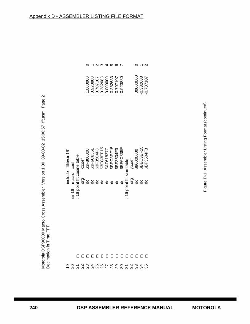
Appendix D - ASSEMBLER LISTING FILE FORMAT
240 DSP ASSEMBLER REFERENCE MANUAL MOTOROLA
Mot
orol
a D
SP
9600
0 M
acro
Cro
ss A
ssem
bler
Ver
sion
1.0
0 8
9-03
-02
15:
00:5
7 ff
t.asm
Pag
e 2
Dec
imat
ion
in T
ime
FF
T
19in
clud
e'ff
tlib/
sin1
6'20
sin1
6m
acro
coef
21m
; 16
poin
t fft
cosi
ne ta
ble
22m
org
x:co
ef23
mdc
$3F
8000
00; 1
.000
000
024
mdc
$3F
6C83
5E; 0
.923
880
125
mdc
$3F
3504
F3
; 0.7
0710
72
26m
dc$3
EC
3EF
15; 0
.382
683
327
mdc
$AF
6183
7C; 0
.000
000
428
mdc
$BE
C3E
F15
;-0.
3826
835
29m
dc$B
F35
04F
3;-
0.70
7107
630
mdc
$BF
6C83
5E;-
0.92
3880
731
m; 1
6 po
int f
ft si
ne ta
ble
32m
org
y:co
ef33
mdc
$800
0000
0; 0
0000
000
034
mdc
$BE
C3E
F15
;-0.
3826
831
35m
dc$B
F35
04F
3;-
0.70
7107
2
Fig
ure
D-1
Ass
embl
er L
istin
g F
orm
at (
cont
inue
d)

Appendix D - ASSEMBLER LISTING FILE FORMAT
MOTOROLA DSP ASSEMBLER REFERENCE MANUAL 241
Mot
orol
a D
SP
9600
0 M
acro
Cro
ss A
ssem
bler
Ver
sion
1.0
0 8
9-03
-02
15:
00:5
7 ff
tlib/
sin1
6.as
m P
age
3D
ecim
atio
n in
Tim
e F
FT
36m
dc$B
F6C
835E
;-0.
9238
803
37m
dc$B
F80
0000
;-1.
0000
004
38m
dc$B
F6C
835E
;-0.
9238
805
39m
dc$B
F35
04F
3;-
0.70
7107
640
mdc
$BE
C3E
F15
;-0.
3826
837
41m
endm
42si
n16
coef
63 64op
tno
md,
mex
65P
:000
0000
0or
gp:
rese
t66
P:0
0000
000
0381
3F80
jmp
star
t67 68
P:0
0000
200
org
p:st
art
151
ditff
tpo
ints
,dat
a,co
ef,s
ize
152
+;
153
+;R
adix
2 D
ecim
atio
n in
Tim
e In
-Pla
ce F
ast F
ourie
r T
rans
form
Rou
tine
154
+;
Fig
ure
D-1
Ass
embl
er L
istin
g F
orm
at (
cont
inue
d)
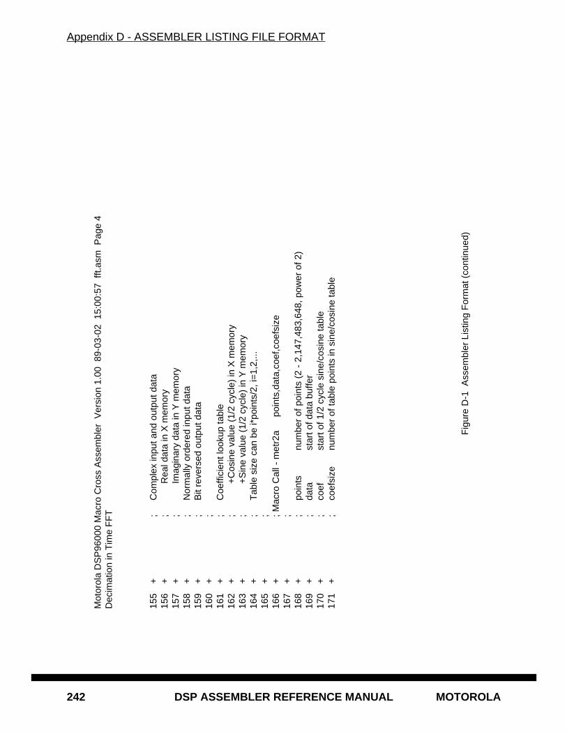
Appendix D - ASSEMBLER LISTING FILE FORMAT
242 DSP ASSEMBLER REFERENCE MANUAL MOTOROLA
Mot
orol
a D
SP
9600
0 M
acro
Cro
ss A
ssem
bler
Ver
sion
1.0
0 8
9-03
-02
15:
00:5
7 ff
t.asm
Pag
e 4
Dec
imat
ion
in T
ime
FF
T
155
+;
Com
plex
inpu
t and
out
put d
ata
156
+;
Rea
l dat
a in
X m
emor
y15
7+
;Im
agin
ary
data
in Y
mem
ory
158
+;
Nor
mal
ly o
rder
ed in
put d
ata
159
+;
Bit
reve
rsed
out
put d
ata
160
+;
161
+;
Coe
ffici
ent l
ooku
p ta
ble
162
+;
+C
osin
e va
lue
(1/2
cyc
le)
in X
mem
ory
163
+;
+S
ine
valu
e (1
/2 c
ycle
) in
Y m
emor
y16
4+
;T
able
siz
e ca
n be
i*po
ints
/2, i
=1,
2,...
165
+;
166
+; M
acro
Cal
l - m
etr2
apo
ints
,dat
a,co
ef,c
oefs
ize
167
+;
168
+;
poin
tsnu
mbe
r of
poi
nts
(2 -
2,1
47,4
83,6
48, p
ower
of 2
)16
9+
;da
tast
art o
f dat
a bu
ffer
170
+;
coef
star
t of 1
/2 c
ycle
sin
e/co
sine
tabl
e17
1+
;co
efsi
zenu
mbe
r of
tabl
e po
ints
in s
ine/
cosi
ne ta
ble
Fig
ure
D-1
Ass
embl
er L
istin
g F
orm
at (
cont
inue
d)

Appendix D - ASSEMBLER LISTING FILE FORMAT
MOTOROLA DSP ASSEMBLER REFERENCE MANUAL 243
Mot
orol
a D
SP
9600
0 M
acro
Cro
ss A
ssem
bler
Ver
sion
1.0
0 8
9-03
-02
15:
00:5
7 ff
t.asm
Pag
e 5
Dec
imat
ion
in T
ime
FF
T
172
+;
=
i*po
ints
/2, i
=1,
2,...
(
1 -
2,14
7,48
3,64
8)17
3+
;17
4+
;
+--
----
----
-+17
5+
; ar
----
>
R
adix
2
--
--->
ar'
176
+; a
i --
-->
But
terf
ly
---
-->
ai'
177
+; b
r --
--->
A'=
A+
B*W
k -
----
> b
r'17
8+
; bi -
----
>
B'=
A-B
*Wk
---
-->
bi'
179
+;
+
----
----
---+
180
+;
^
^18
1+
;18
2+
;
wr
w
i18
3+
;18
4+
; wrk
= c
osin
e(k*
pi/p
oint
s) t
able
185
+; w
ik =
sin
e(k*
pi/p
oint
s)
ta
ble
186
+;
187
+; a
r' =
ar
+ (
wr*
br +
wi*
bi)
188
+; a
i' =
ai +
(w
r*bi
- w
i*br
)
Fig
ure
D-1
Ass
embl
er L
istin
g F
orm
at (
cont
inue
d)
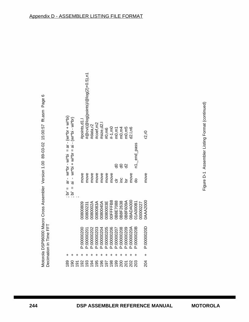
Appendix D - ASSEMBLER LISTING FILE FORMAT
244 DSP ASSEMBLER REFERENCE MANUAL MOTOROLA
Mot
orol
a D
SP
9600
0 M
acro
Cro
ss A
ssem
bler
Ver
sion
1.0
0 8
9-03
-02
15:
00:5
7 ff
t.asm
Pag
e 6
Dec
imat
ion
in T
ime
FF
T
189
+; b
r' =
ar
- w
r*br
- w
i*bi
= a
r -
(wr*
br +
wi*
bi)
190
+; b
i' =
ai
- w
r*bi
+ w
i*br
= a
i - (
wr*
bi -
wi*
br)
191
+;
192
+P
:000
0020
000
8008
09m
ove
#poi
nts,
d1.l
193
+P
:000
0020
100
8002
31m
ove
#@cv
i(@lo
g(po
ints
)/@
log(
2)+
0.5)
,n1
194
+P
:000
0020
200
8000
2Am
ove
#dat
a,r2
195
+P
:000
0020
300
8008
3Am
ove
#coe
f,m2
196
+P
:000
0020
400
8004
0Am
ove
#siz
e,d2
.l19
7+
P:0
0000
205
0080
003E
mov
e#0
,m6
198
+P
:000
0020
600
FF
FF
B8
mov
e#-
1,m
019
9+
P:0
0000
207
0B8E
7088
clr
d0m
0,m
120
0+
P:0
0000
208
0B8F
2638
inc
d0m
0,m
420
1+
P:0
0000
209
0B8F
609A
lsr
d2m
0,m
520
2+
P:0
0000
20A
08A
DA
000
mov
ed2
.l,n6
203
+P
:000
0020
B01
A00
0B1
don1
,_en
d_pa
ss00
0002
2720
4+
P:0
0000
20D
0AA
A20
00m
ove
r2,r
0
Fig
ure
D-1
Ass
embl
er L
istin
g F
orm
at (
cont
inue
d)
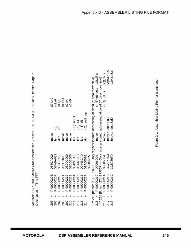
Appendix D - ASSEMBLER LISTING FILE FORMAT
MOTOROLA DSP ASSEMBLER REFERENCE MANUAL 245
Mot
orol
a D
SP
9600
0 M
acro
Cro
ss A
ssem
bler
Ver
sion
1.0
0 8
9-03
-02
15:
00:5
7 ff
t.asm
Pag
e 7
Dec
imat
ion
in T
ime
FF
T
205
+P
:000
0020
E08
8CA
000
mov
ed0
.l,n2
206
+P
:000
0020
F0B
AB
A05
9ls
rd1
m2,
r620
7+
P:0
0000
210
089C
2779
dec
d1d1
.l,n0
208
+P
:000
0021
108
9C60
00m
ove
d1.l,
n120
9+
P:0
0000
212
0B0D
2000
mov
en0
,n4
210
+P
:000
0021
30B
0D60
00m
ove
n0,n
521
1+
P:0
0000
214
0042
20A
9le
a(r
0)+
n0,r
121
2+
P:0
0000
215
0044
20A
Cle
a(r
0)-,
r421
3+
P:0
0000
216
0044
60A
Dle
a(r
1)-,
r521
4+
P:0
0000
217
01A
000B
2do
n2,_
end_
grp
0000
0225
****
215
[fft.
asm
27]
: ER
RO
R -
-- O
nly
regi
ster
indi
rect
add
ress
ing
allo
wed
(Y
dat
a m
ove
field
)21
5+
P:0
0000
219
0000
6004
mov
ex:
(r6)
+n6
,d9.
sy:
(),d
8.s
****
216
[fft.
asm
27]
: ER
RO
R -
-- O
nly
regi
ster
indi
rect
add
ress
ing
allo
wed
(Y
dat
a m
ove
field
)21
6+
P:0
0000
21A
0000
6004
mov
ex:
(r1)
+,d
6.s
y:()
,d7.
s21
7+
P:0
0000
21B
3C29
77D
3fm
py.s
d8,d
7,d3
y:(r
5),d
2.s
218
+P
:000
0021
C3C
5936
F0
fmpy
.sd9
,d6,
d0y:
(r4)
,d5.
s
Fig
ure
D-1
Ass
embl
er L
istin
g F
orm
at (
cont
inue
d)
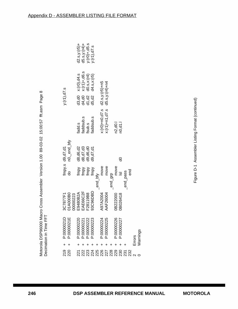
Appendix D - ASSEMBLER LISTING FILE FORMAT
246 DSP ASSEMBLER REFERENCE MANUAL MOTOROLA
Mot
orol
a D
SP
9600
0 M
acro
Cro
ss A
ssem
bler
Ver
sion
1.0
0 8
9-03
-02
15:
00:5
7 ff
t.asm
Pag
e 8
Dec
imat
ion
in T
ime
FF
T
219
+P
:000
0021
D3C
7877
F1
fmpy
.sd9
,d7,
d1y:
(r1)
,d7.
s22
0+
P:0
0000
21E
01A
000B
0do
n0,_
end_
bfy
0000
0223
221
+P
:000
0022
0E
9480
B2A
fmpy
d8,d
6,d2
fadd
.sd3
,d0
x:(r
0),d
4.s
d2.s
,y:(
r5)+
222
+P
:000
0022
1E
AE
66C
2Ffm
pyd8
,d7,
d3fa
ddsu
b.s
d4,d
0x:
(r1)
+,d
6.s
d5.s
,y:(
r4)+
223
+P
:000
0022
2F
2811
9B8
fmpy
d9,d
6,d0
fsub
.sd1
,d2
d0.s
,x:(
r4)
y:(r
0)+
,d5.
s22
4+
P:0
0000
223
93C
96D
BD
fmpy
d9,d
7,d1
fadd
sub.
sd5
,d2
d4.s
,x:(
r5)
y:(r
1),d
7.s
225
+_e
nd_b
fy22
6+
P:0
0000
224
A97
A20
04m
ove
x:(r
0)+
n0,d
7.s
d2.s
,y:(
r5)+
n522
7+
P:0
0000
225
AA
F26
004
mov
ex:
(r1)
+n1
,d7.
sd5
.s,y
:(r4
)+n4
228
+_e
nd_g
rp22
9+
P:0
0000
226
0B22
2000
mov
en2
,d0.
l23
0+
P:0
0000
227
0B02
6418
lsl
d0n0
,d1.
l23
1+
_end
_pas
s23
2en
d2
Err
ors
0W
arni
ngs
Fig
ure
D-1
Ass
embl
er L
istin
g F
orm
at (
cont
inue
d)
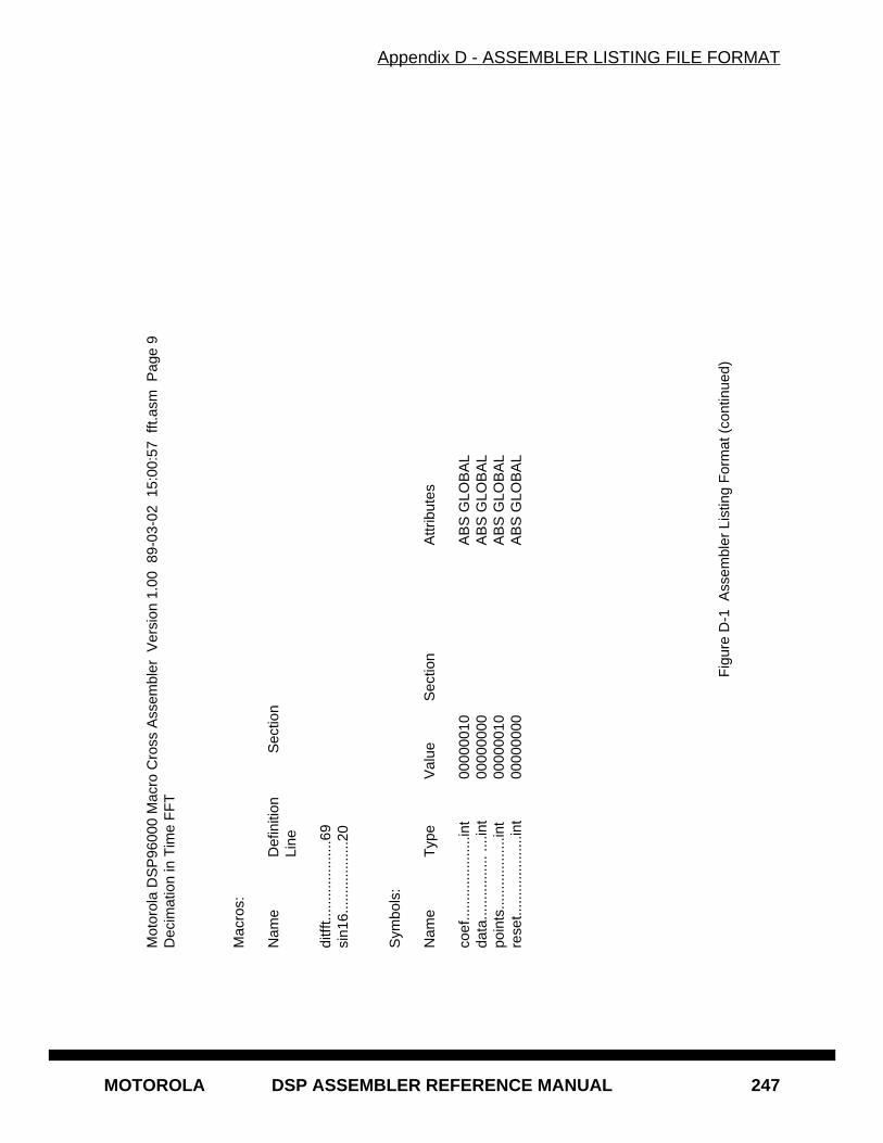
Appendix D - ASSEMBLER LISTING FILE FORMAT
MOTOROLA DSP ASSEMBLER REFERENCE MANUAL 247
Mot
orol
a D
SP
9600
0 M
acro
Cro
ss A
ssem
bler
Ver
sion
1.0
0 8
9-03
-02
15:
00:5
7 ff
t.asm
Pag
e 9
Dec
imat
ion
in T
ime
FF
T
Mac
ros:
Nam
eD
efin
ition
Sec
tion
Line
ditff
t.....
......
......
...69
sin1
6....
......
......
..20
Sym
bols
:
Nam
eT
ype
Val
ueS
ectio
nA
ttrib
utes
coef
......
......
......
...in
t00
0000
10A
BS
GLO
BA
Lda
ta...
......
......
. ....
int
0000
0000
AB
S G
LOB
AL
poin
ts...
......
......
...in
t00
0000
10A
BS
GLO
BA
Lre
set..
......
......
......
int
0000
0000
AB
S G
LOB
AL
Fig
ure
D-1
Ass
embl
er L
istin
g F
orm
at (
cont
inue
d)
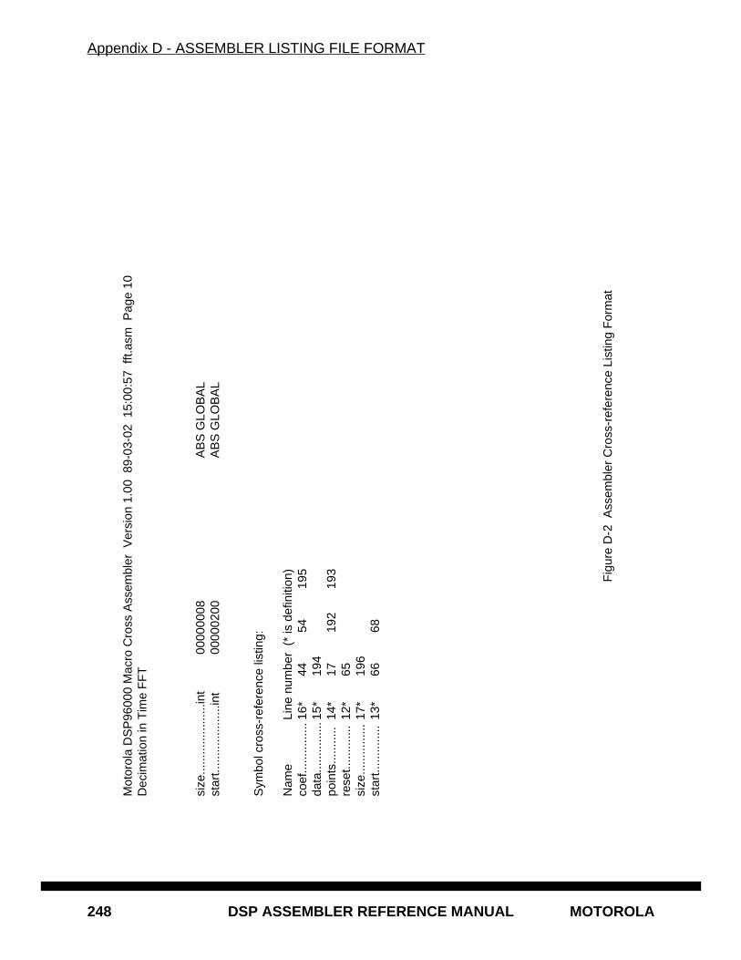
Appendix D - ASSEMBLER LISTING FILE FORMAT
248 DSP ASSEMBLER REFERENCE MANUAL MOTOROLA
Mot
orol
a D
SP
9600
0 M
acro
Cro
ss A
ssem
bler
Ver
sion
1.0
0 8
9-03
-02
15:
00:5
7 ff
t.asm
Pag
e 10
Dec
imat
ion
in T
ime
FF
T
size
......
......
......
...in
t00
0000
08A
BS
GLO
BA
Lst
art..
......
......
......
int
0000
0200
AB
S G
LOB
AL
Sym
bol c
ross
-ref
eren
ce li
stin
g:
Nam
eLi
ne n
umbe
r (
* is
def
initi
on)
coef
......
......
...16
*44
5419
5
data
......
......
...15
*19
4
poin
ts...
......
..14
*17
192
193
re
set..
......
.....
12*
65
size
......
......
...17
*19
6
star
t.....
......
...13
*66
68
Fig
ure
D-2
Ass
embl
er C
ross
-ref
eren
ce L
istin
g F
orm
at
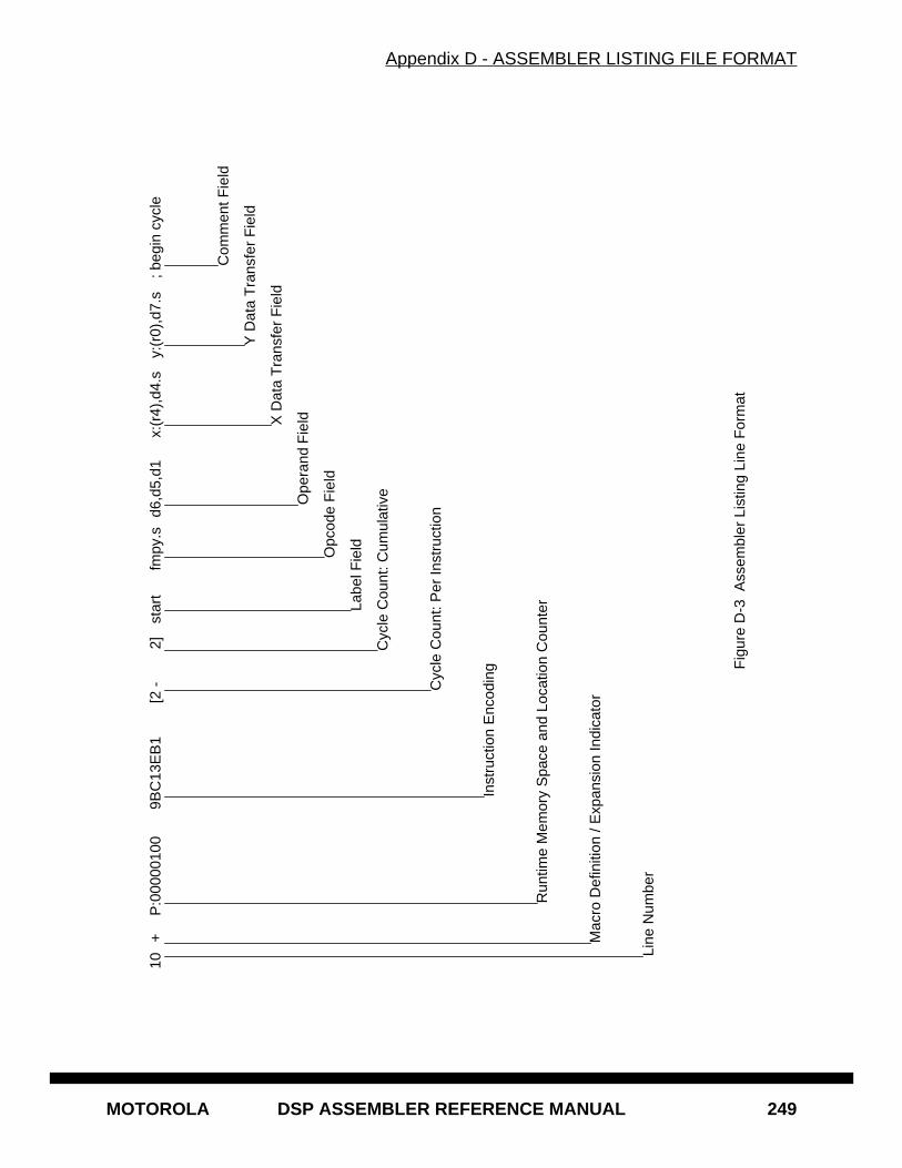
Appendix D - ASSEMBLER LISTING FILE FORMAT
MOTOROLA DSP ASSEMBLER REFERENCE MANUAL 249
10+
P:0
0000
100
9BC
13E
B1
[2 -
2]
star
tfm
py.s
d6,d
5,d1
x:(r
4),d
4.s
y:(r
0),d
7.s
; beg
in c
ycle
F
igur
e D
-3 A
ssem
bler
Lis
ting
Line
For
mat
Line
Num
ber
Mac
ro D
efin
ition
/ E
xpan
sion
Indi
cato
r
Run
time
Mem
ory
Spa
ce a
nd L
ocat
ion
Cou
nter
Inst
ruct
ion
Enc
odin
g
Cyc
le C
ount
: Per
Inst
ruct
ion
Cyc
le C
ount
: Cum
ulat
ive
Labe
l Fie
ldOpc
ode
Fie
ld
Ope
rand
Fie
ldX D
ata
Tra
nsfe
r F
ield
Y D
ata
Tra
nsfe
r F
ield
Com
men
t Fie
ld
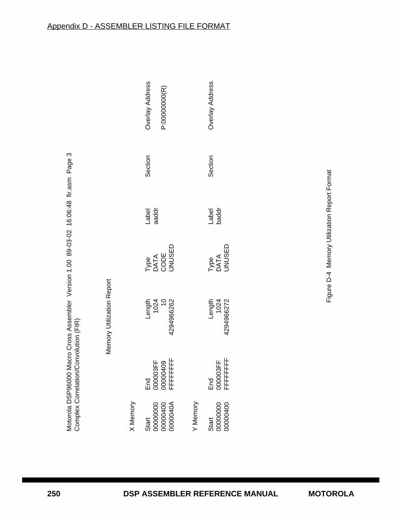
Appendix D - ASSEMBLER LISTING FILE FORMAT
250 DSP ASSEMBLER REFERENCE MANUAL MOTOROLA
Mot
orol
a D
SP
9600
0 M
acro
Cro
ss A
ssem
bler
Ver
sion
1.0
0 8
9-03
-02
16:
06:4
8 fi
r.as
m P
age
3C
ompl
ex C
orre
latio
n/C
onvo
lutio
n (F
IR)
Mem
ory
Util
izat
ion
Rep
ort
X M
emor
y
Sta
rtE
ndLe
ngth
Typ
eLa
bel
Sec
tion
Ove
rlay
Add
ress
0000
0000
0000
03F
F
1024
DA
TA
aadd
r00
0004
0000
0004
09
1
0C
OD
EP
:000
0000
0(R
)00
0004
0AF
FF
FF
FF
F
429
4966
262
UN
US
ED
Y M
emor
y
Sta
rtE
ndLe
ngth
Typ
eLa
bel
Sec
tion
Ove
rlay
Add
ress
0000
0000
0000
03F
F
1024
DA
TA
badd
r00
0004
00F
FF
FF
FF
F
429
4966
272
UN
US
ED
Fig
ure
D-4
Mem
ory
Util
izat
ion
Rep
ort F
orm
at
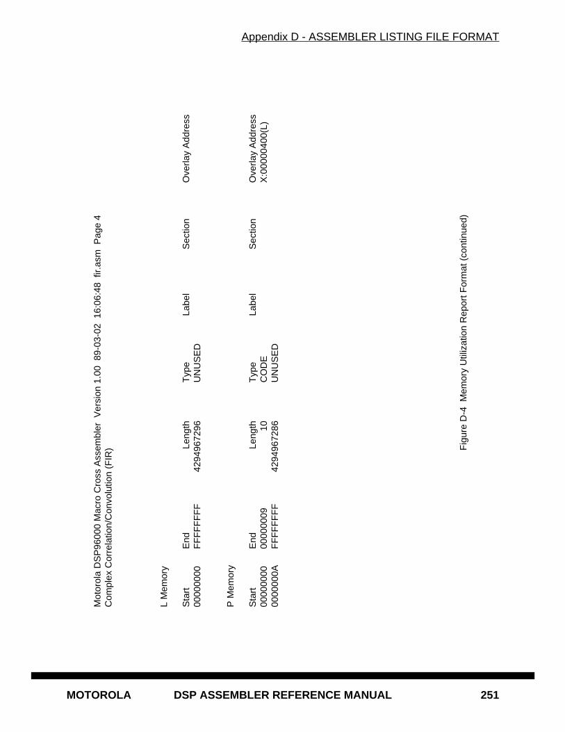
Appendix D - ASSEMBLER LISTING FILE FORMAT
MOTOROLA DSP ASSEMBLER REFERENCE MANUAL 251
Mot
orol
a D
SP
9600
0 M
acro
Cro
ss A
ssem
bler
Ver
sion
1.0
0 8
9-03
-02
16:
06:4
8 fi
r.as
m P
age
4C
ompl
ex C
orre
latio
n/C
onvo
lutio
n (F
IR)
L M
emor
y
Sta
rtE
ndLe
ngth
Typ
eLa
bel
Sec
tion
Ove
rlay
Add
ress
0000
0000
FF
FF
FF
FF
4
2949
6729
6U
NU
SE
D
P M
emor
y
Sta
rtE
ndLe
ngth
Typ
eLa
bel
Sec
tion
Ove
rlay
Add
ress
0000
0000
0000
0009
10
CO
DE
X:0
0000
400(
L)00
0000
0AF
FF
FF
FF
F
429
4967
286
UN
US
ED
Fig
ure
D-4
Mem
ory
Util
izat
ion
Rep
ort F
orm
at (
cont
inue
d)
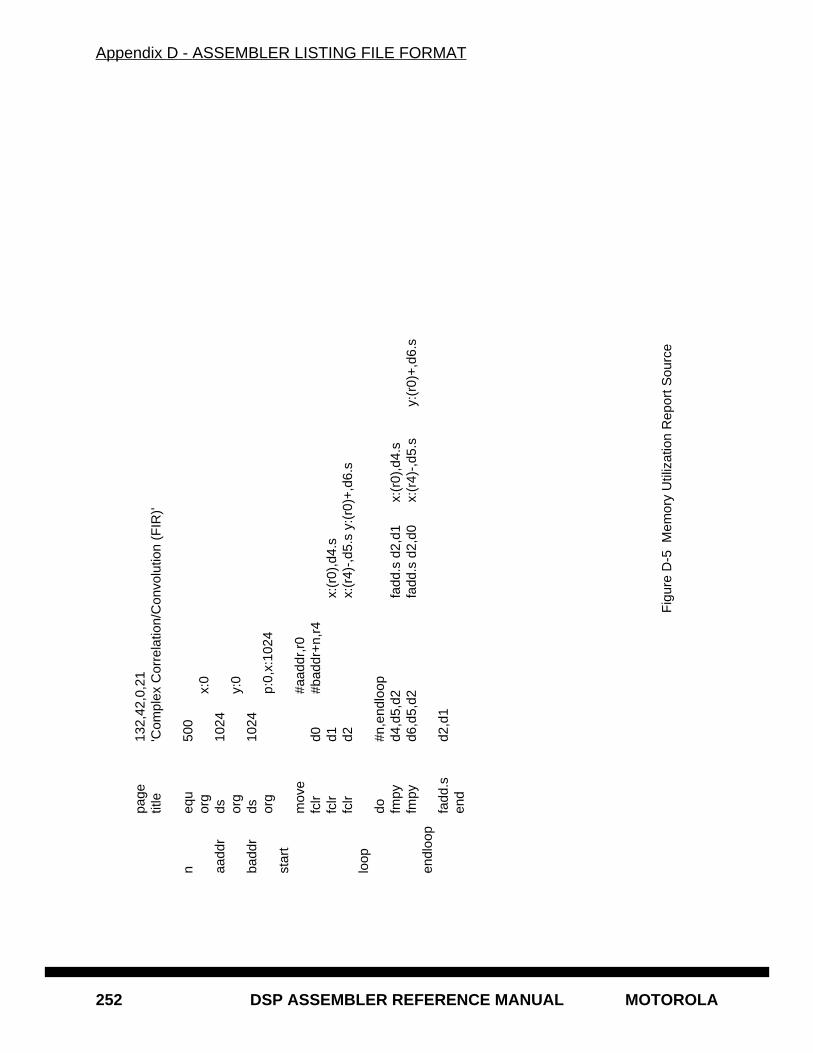
Appendix D - ASSEMBLER LISTING FILE FORMAT
252 DSP ASSEMBLER REFERENCE MANUAL MOTOROLA
pa
ge13
2,42
,0,2
1
title
'Com
plex
Cor
rela
tion/
Con
volu
tion
(FIR
)' n
equ
500
org
x:0
aadd
rds
1024
or
gy:
0 ba
ddr
ds10
24
org
p:0,
x:10
24
star
t m
ove
#aad
dr,r
0 fc
lrd0
#bad
dr+
n,r4
fc
lrd1
x:(r
0),d
4.s
fclr
d2x:
(r4)
-,d5
.s y
:(r0
)+,d
6.s
loop
do
#n,e
ndlo
op
fmpy
d4,d
5,d2
fadd
.s d
2,d1
x:(r
0),d
4.s
fmpy
d6,d
5,d2
fadd
.s d
2,d0
x:(r
4)-,
d5.s
y:(r
0)+
,d6.
s en
dloo
p fa
dd.s
d2,d
1 en
d
Fig
ure
D-5
Mem
ory
Util
izat
ion
Rep
ort S
ourc
e
MOTOROLA DSP ASSEMBLER REFERENCE MANUAL 253
Appendix EMOTOROLA DSP OBJECT FILE FORMAT (COFF)
E.1 INTRODUCTION
The Motorola DSP assembler and linker produce a binary object file in a modified form ofthe AT&T Common Object File Format (COFF). COFF is a formal definition for the struc-ture of machine code files. It originated with Unix System V but has sufficient flexibilityand generality to be useful in non-hosted environments. In particular, COFF supportsuser-defined sections and contains extensive information for symbolic software testingand debugging.
Later sections describe the COFF implementation for the Motorola family of digital signalprocessors. The DSP COFF format has been altered to support multiple memory spacesand normalized to promote transportability of object files among host processors. Seesection E.4 for a list of differences between the Motorola DSP object file format and stan-dard COFF. For a more general discussion of COFF the following reference may be use-ful:
Gintaras R. Gircys, Understanding and Using COFF , O’Reilly & Associates,1988 (ISBN 0-937175-31-5).
E.2 OBJECT FILE STRUCTURE
A DSP COFF object file consists of up to eight groups of object file information. Some ofthese groups are optional, depending on the type of object file generated, and others mayhave repeating occurrences. The basic object file components are:
• File header
• Optional header
• Section headers
• Section data
• Relocation information
• Line numbers
• Symbol table
• String table
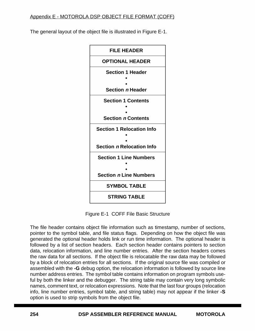
Appendix E - MOTOROLA DSP OBJECT FILE FORMAT (COFF)
254 DSP ASSEMBLER REFERENCE MANUAL MOTOROLA
The general layout of the object file is illustrated in Figure E-1.
Figure E-1 COFF File Basic Structure
The file header contains object file information such as timestamp, number of sections,pointer to the symbol table, and file status flags. Depending on how the object file wasgenerated the optional header holds link or run time information. The optional header isfollowed by a list of section headers. Each section header contains pointers to sectiondata, relocation information, and line number entries. After the section headers comesthe raw data for all sections. If the object file is relocatable the raw data may be followedby a block of relocation entries for all sections. If the original source file was compiled orassembled with the -G debug option, the relocation information is followed by source linenumber address entries. The symbol table contains information on program symbols use-ful by both the linker and the debugger. The string table may contain very long symbolicnames, comment text, or relocation expressions. Note that the last four groups (relocationinfo, line number entries, symbol table, and string table) may not appear if the linker -Soption is used to strip symbols from the object file.
FILE HEADER
OPTIONAL HEADER
Section 1 Header••
Section n Header
Section 1 Contents••
Section n Contents
Section 1 Relocation Info••
Section n Relocation Info
Section 1 Line Numbers••
Section n Line Numbers
SYMBOL TABLE
STRING TABLE
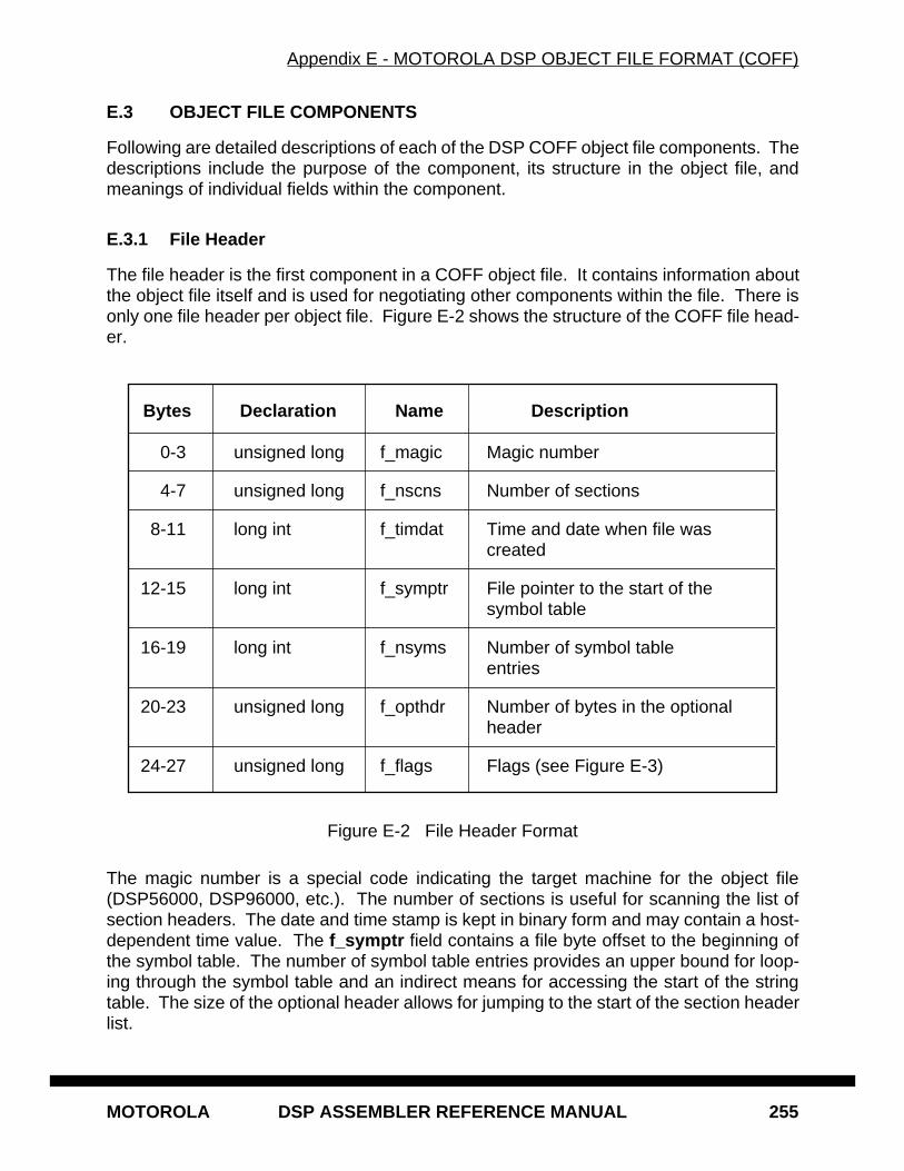
Appendix E - MOTOROLA DSP OBJECT FILE FORMAT (COFF)
MOTOROLA DSP ASSEMBLER REFERENCE MANUAL 255
E.3 OBJECT FILE COMPONENTS
Following are detailed descriptions of each of the DSP COFF object file components. Thedescriptions include the purpose of the component, its structure in the object file, andmeanings of individual fields within the component.
E.3.1 File Header
The file header is the first component in a COFF object file. It contains information aboutthe object file itself and is used for negotiating other components within the file. There isonly one file header per object file. Figure E-2 shows the structure of the COFF file head-er.
Figure E-2 File Header Format
The magic number is a special code indicating the target machine for the object file(DSP56000, DSP96000, etc.). The number of sections is useful for scanning the list ofsection headers. The date and time stamp is kept in binary form and may contain a host-dependent time value. The f_symptr field contains a file byte offset to the beginning ofthe symbol table. The number of symbol table entries provides an upper bound for loop-ing through the symbol table and an indirect means for accessing the start of the stringtable. The size of the optional header allows for jumping to the start of the section headerlist.
Bytes Declaration Name Description
0-3 unsigned long f_magic Magic number
4-7 unsigned long f_nscns Number of sections
8-11 long int f_timdat Time and date when file wascreated
12-15 long int f_symptr File pointer to the start of thesymbol table
16-19 long int f_nsyms Number of symbol tableentries
20-23 unsigned long f_opthdr Number of bytes in the optionalheader
24-27 unsigned long f_flags Flags (see Figure E-3)
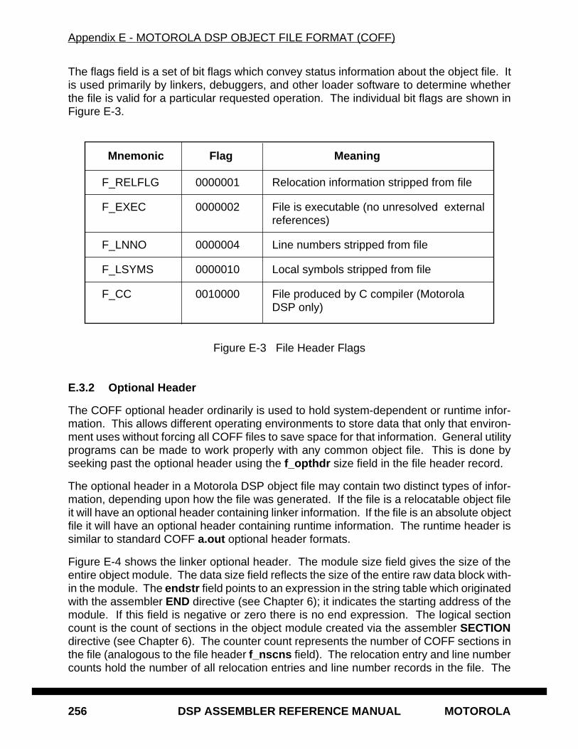
Appendix E - MOTOROLA DSP OBJECT FILE FORMAT (COFF)
256 DSP ASSEMBLER REFERENCE MANUAL MOTOROLA
The flags field is a set of bit flags which convey status information about the object file. Itis used primarily by linkers, debuggers, and other loader software to determine whetherthe file is valid for a particular requested operation. The individual bit flags are shown inFigure E-3.
Figure E-3 File Header Flags
E.3.2 Optional Header
The COFF optional header ordinarily is used to hold system-dependent or runtime infor-mation. This allows different operating environments to store data that only that environ-ment uses without forcing all COFF files to save space for that information. General utilityprograms can be made to work properly with any common object file. This is done byseeking past the optional header using the f_opthdr size field in the file header record.
The optional header in a Motorola DSP object file may contain two distinct types of infor-mation, depending upon how the file was generated. If the file is a relocatable object fileit will have an optional header containing linker information. If the file is an absolute objectfile it will have an optional header containing runtime information. The runtime header issimilar to standard COFF a.out optional header formats.
Figure E-4 shows the linker optional header. The module size field gives the size of theentire object module. The data size field reflects the size of the entire raw data block with-in the module. The endstr field points to an expression in the string table which originatedwith the assembler END directive (see Chapter 6); it indicates the starting address of themodule. If this field is negative or zero there is no end expression. The logical sectioncount is the count of sections in the object module created via the assembler SECTIONdirective (see Chapter 6). The counter count represents the number of COFF sections inthe file (analogous to the file header f_nscns field). The relocation entry and line numbercounts hold the number of all relocation entries and line number records in the file. The
Mnemonic Flag Meaning
F_RELFLG 0000001 Relocation information stripped from file
F_EXEC 0000002 File is executable (no unresolved externalreferences)
F_LNNO 0000004 Line numbers stripped from file
F_LSYMS 0000010 Local symbols stripped from file
F_CC 0010000 File produced by C compiler (MotorolaDSP only)
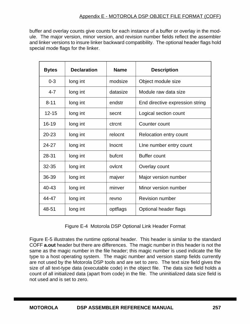
Appendix E - MOTOROLA DSP OBJECT FILE FORMAT (COFF)
MOTOROLA DSP ASSEMBLER REFERENCE MANUAL 257
buffer and overlay counts give counts for each instance of a buffer or overlay in the mod-ule. The major version, minor version, and revision number fields reflect the assemblerand linker versions to insure linker backward compatibility. The optional header flags holdspecial mode flags for the linker.
Figure E-4 Motorola DSP Optional Link Header Format
Figure E-5 illustrates the runtime optional header. This header is similar to the standardCOFF a.out header but there are differences. The magic number in this header is not thesame as the magic number in the file header; this magic number is used indicate the filetype to a host operating system. The magic number and version stamp fields currentlyare not used by the Motorola DSP tools and are set to zero. The text size field gives thesize of all text-type data (executable code) in the object file. The data size field holds acount of all initialized data (apart from code) in the file. The uninitialized data size field isnot used and is set to zero.
Bytes Declaration Name Description
0-3 long int modsize Object module size
4-7 long int datasize Module raw data size
8-11 long int endstr End directive expression string
12-15 long int secnt Logical section count
16-19 long int ctrcnt Counter count
20-23 long int relocnt Relocation entry count
24-27 long int lnocnt LIne number entry count
28-31 long int bufcnt Buffer count
32-35 long int ovlcnt Overlay count
36-39 long int majver Major version number
40-43 long int minver Minor version number
44-47 long int revno Revision number
48-51 long int optflags Optional header flags
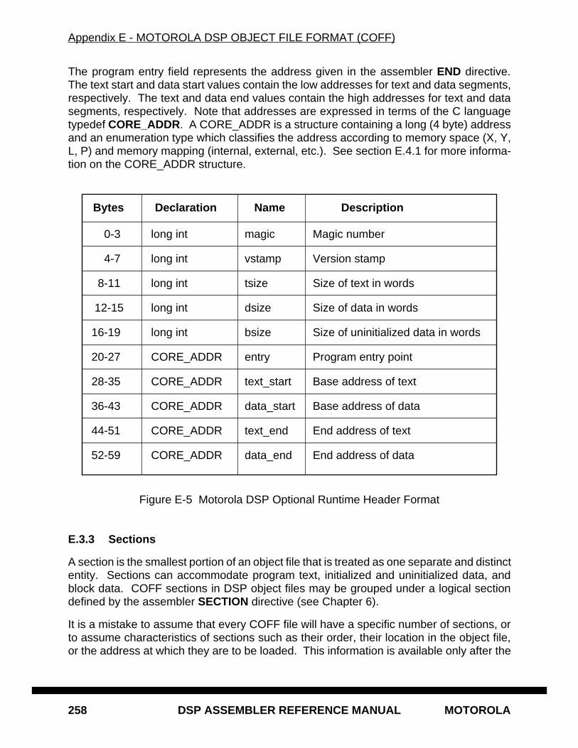
Appendix E - MOTOROLA DSP OBJECT FILE FORMAT (COFF)
258 DSP ASSEMBLER REFERENCE MANUAL MOTOROLA
The program entry field represents the address given in the assembler END directive.The text start and data start values contain the low addresses for text and data segments,respectively. The text and data end values contain the high addresses for text and datasegments, respectively. Note that addresses are expressed in terms of the C languagetypedef CORE_ADDR. A CORE_ADDR is a structure containing a long (4 byte) addressand an enumeration type which classifies the address according to memory space (X, Y,L, P) and memory mapping (internal, external, etc.). See section E.4.1 for more informa-tion on the CORE_ADDR structure.
Figure E-5 Motorola DSP Optional Runtime Header Format
E.3.3 Sections
A section is the smallest portion of an object file that is treated as one separate and distinctentity. Sections can accommodate program text, initialized and uninitialized data, andblock data. COFF sections in DSP object files may be grouped under a logical sectiondefined by the assembler SECTION directive (see Chapter 6).
It is a mistake to assume that every COFF file will have a specific number of sections, orto assume characteristics of sections such as their order, their location in the object file,or the address at which they are to be loaded. This information is available only after the
Bytes Declaration Name Description
0-3 long int magic Magic number
4-7 long int vstamp Version stamp
8-11 long int tsize Size of text in words
12-15 long int dsize Size of data in words
16-19 long int bsize Size of uninitialized data in words
20-27 CORE_ADDR entry Program entry point
28-35 CORE_ADDR text_start Base address of text
36-43 CORE_ADDR data_start Base address of data
44-51 CORE_ADDR text_end End address of text
52-59 CORE_ADDR data_end End address of data
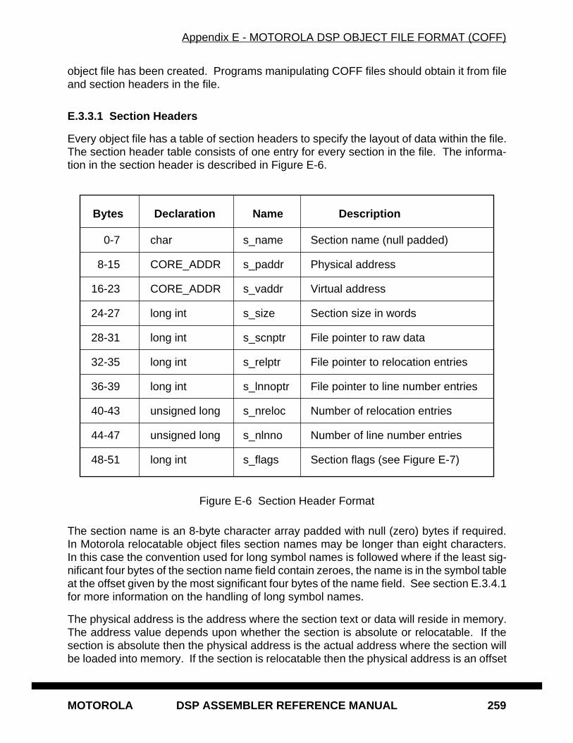
Appendix E - MOTOROLA DSP OBJECT FILE FORMAT (COFF)
MOTOROLA DSP ASSEMBLER REFERENCE MANUAL 259
object file has been created. Programs manipulating COFF files should obtain it from fileand section headers in the file.
E.3.3.1 Section Headers
Every object file has a table of section headers to specify the layout of data within the file.The section header table consists of one entry for every section in the file. The informa-tion in the section header is described in Figure E-6.
Figure E-6 Section Header Format
The section name is an 8-byte character array padded with null (zero) bytes if required.In Motorola relocatable object files section names may be longer than eight characters.In this case the convention used for long symbol names is followed where if the least sig-nificant four bytes of the section name field contain zeroes, the name is in the symbol tableat the offset given by the most significant four bytes of the name field. See section E.3.4.1for more information on the handling of long symbol names.
The physical address is the address where the section text or data will reside in memory.The address value depends upon whether the section is absolute or relocatable. If thesection is absolute then the physical address is the actual address where the section willbe loaded into memory. If the section is relocatable then the physical address is an offset
Bytes Declaration Name Description
0-7 char s_name Section name (null padded)
8-15 CORE_ADDR s_paddr Physical address
16-23 CORE_ADDR s_vaddr Virtual address
24-27 long int s_size Section size in words
28-31 long int s_scnptr File pointer to raw data
32-35 long int s_relptr File pointer to relocation entries
36-39 long int s_lnnoptr File pointer to line number entries
40-43 unsigned long s_nreloc Number of relocation entries
44-47 unsigned long s_nlnno Number of line number entries
48-51 long int s_flags Section flags (see Figure E-7)
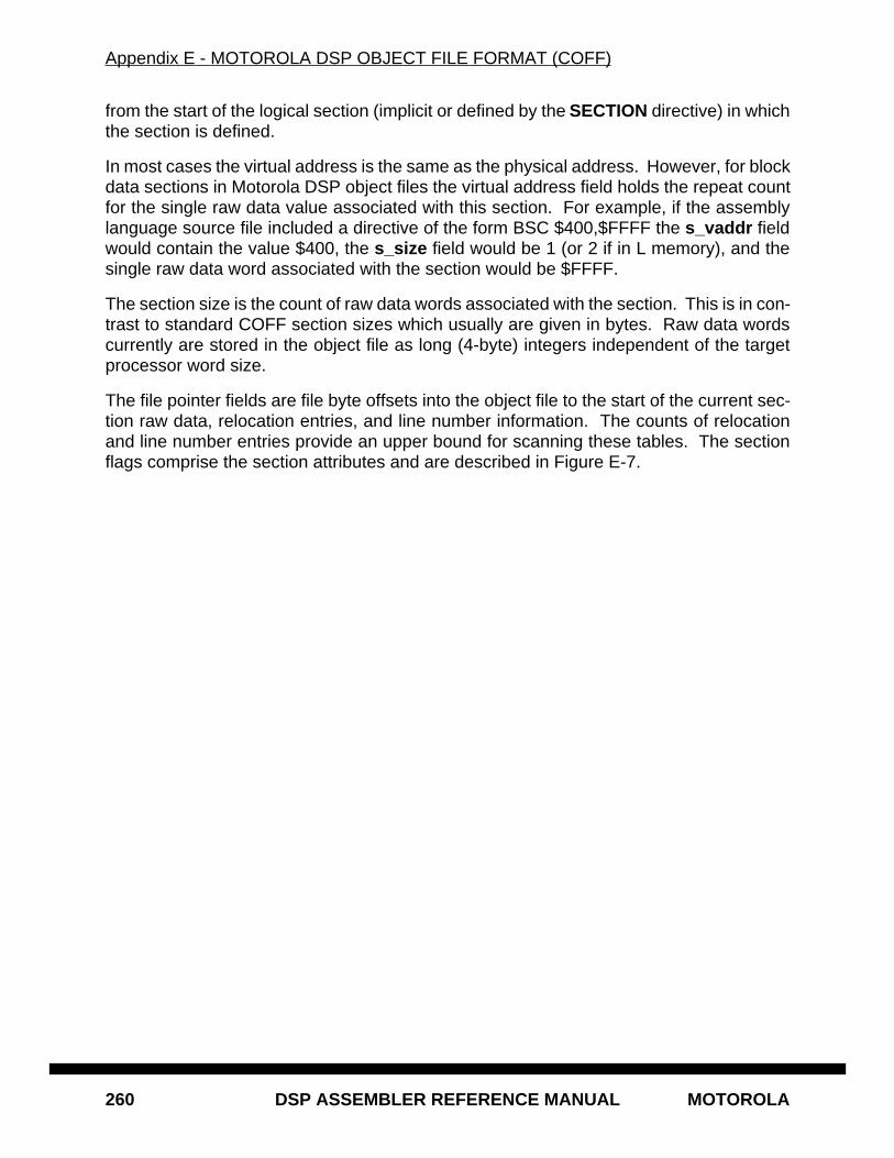
Appendix E - MOTOROLA DSP OBJECT FILE FORMAT (COFF)
260 DSP ASSEMBLER REFERENCE MANUAL MOTOROLA
from the start of the logical section (implicit or defined by the SECTION directive) in whichthe section is defined.
In most cases the virtual address is the same as the physical address. However, for blockdata sections in Motorola DSP object files the virtual address field holds the repeat countfor the single raw data value associated with this section. For example, if the assemblylanguage source file included a directive of the form BSC $400,$FFFF the s_vaddr fieldwould contain the value $400, the s_size field would be 1 (or 2 if in L memory), and thesingle raw data word associated with the section would be $FFFF.
The section size is the count of raw data words associated with the section. This is in con-trast to standard COFF section sizes which usually are given in bytes. Raw data wordscurrently are stored in the object file as long (4-byte) integers independent of the targetprocessor word size.
The file pointer fields are file byte offsets into the object file to the start of the current sec-tion raw data, relocation entries, and line number information. The counts of relocationand line number entries provide an upper bound for scanning these tables. The sectionflags comprise the section attributes and are described in Figure E-7.
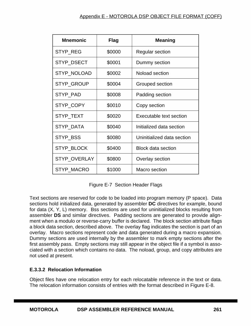
Appendix E - MOTOROLA DSP OBJECT FILE FORMAT (COFF)
MOTOROLA DSP ASSEMBLER REFERENCE MANUAL 261
Figure E-7 Section Header Flags
Text sections are reserved for code to be loaded into program memory (P space). Datasections hold initialized data, generated by assembler DC directives for example, boundfor data (X, Y, L) memory. Bss sections are used for uninitialized blocks resulting fromassembler DS and similar directives. Padding sections are generated to provide align-ment when a modulo or reverse-carry buffer is declared. The block section attribute flagsa block data section, described above. The overlay flag indicates the section is part of anoverlay. Macro sections represent code and data generated during a macro expansion.Dummy sections are used internally by the assembler to mark empty sections after thefirst assembly pass. Empty sections may still appear in the object file if a symbol is asso-ciated with a section which contains no data. The noload, group, and copy attributes arenot used at present.
E.3.3.2 Relocation Information
Object files have one relocation entry for each relocatable reference in the text or data.The relocation information consists of entries with the format described in Figure E-8.
Mnemonic Flag Meaning
STYP_REG $0000 Regular section
STYP_DSECT $0001 Dummy section
STYP_NOLOAD $0002 Noload section
STYP_GROUP $0004 Grouped section
STYP_PAD $0008 Padding section
STYP_COPY $0010 Copy section
STYP_TEXT $0020 Executable text section
STYP_DATA $0040 Initialized data section
STYP_BSS $0080 Uninitialized data section
STYP_BLOCK $0400 Block data section
STYP_OVERLAY $0800 Overlay section
STYP_MACRO $1000 Macro section
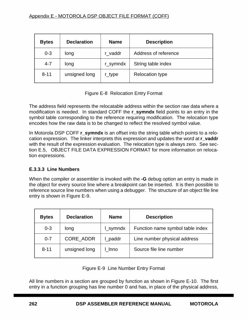
Appendix E - MOTOROLA DSP OBJECT FILE FORMAT (COFF)
262 DSP ASSEMBLER REFERENCE MANUAL MOTOROLA
Figure E-8 Relocation Entry Format
The address field represents the relocatable address within the section raw data where amodification is needed. In standard COFF the r_symndx field points to an entry in thesymbol table corresponding to the reference requiring modification. The relocation typeencodes how the raw data is to be changed to reflect the resolved symbol value.
In Motorola DSP COFF r_symndx is an offset into the string table which points to a relo-cation expression. The linker interprets this expression and updates the word at r_vaddrwith the result of the expression evaluation. The relocation type is always zero. See sec-tion E.5, OBJECT FILE DATA EXPRESSION FORMAT for more information on reloca-tion expressions.
E.3.3.3 Line Numbers
When the compiler or assembler is invoked with the -G debug option an entry is made inthe object for every source line where a breakpoint can be inserted. It is then possible toreference source line numbers when using a debugger. The structure of an object file lineentry is shown in Figure E-9.
Figure E-9 Line Number Entry Format
All line numbers in a section are grouped by function as shown in Figure E-10. The firstentry in a function grouping has line number 0 and has, in place of the physical address,
Bytes Declaration Name Description
0-3 long r_vaddr Address of reference
4-7 long r_symndx String table index
8-11 unsigned long r_type Relocation type
Bytes Declaration Name Description
0-3 long l_symndx Function name symbol table index
0-7 CORE_ADDR l_paddr Line number physical address
8-11 unsigned long l_lnno Source file line number
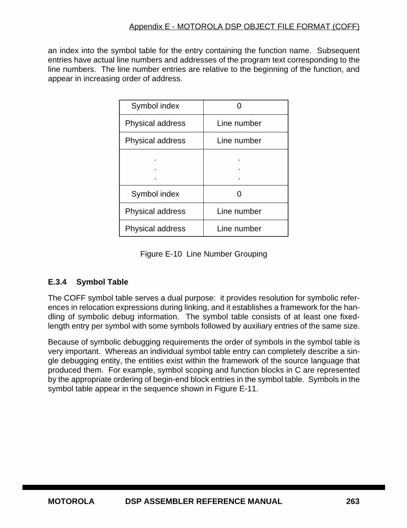
Appendix E - MOTOROLA DSP OBJECT FILE FORMAT (COFF)
MOTOROLA DSP ASSEMBLER REFERENCE MANUAL 263
an index into the symbol table for the entry containing the function name. Subsequententries have actual line numbers and addresses of the program text corresponding to theline numbers. The line number entries are relative to the beginning of the function, andappear in increasing order of address.
Figure E-10 Line Number Grouping
E.3.4 Symbol Table
The COFF symbol table serves a dual purpose: it provides resolution for symbolic refer-ences in relocation expressions during linking, and it establishes a framework for the han-dling of symbolic debug information. The symbol table consists of at least one fixed-length entry per symbol with some symbols followed by auxiliary entries of the same size.
Because of symbolic debugging requirements the order of symbols in the symbol table isvery important. Whereas an individual symbol table entry can completely describe a sin-gle debugging entity, the entities exist within the framework of the source language thatproduced them. For example, symbol scoping and function blocks in C are representedby the appropriate ordering of begin-end block entries in the symbol table. Symbols in thesymbol table appear in the sequence shown in Figure E-11.
Symbol index 0
Physical address Line number
Physical address Line number
. .
. .
. .
Symbol index 0
Physical address Line number
Physical address Line number
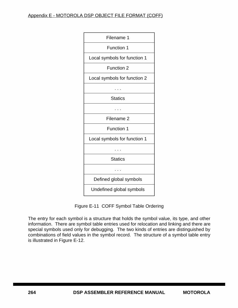
Appendix E - MOTOROLA DSP OBJECT FILE FORMAT (COFF)
264 DSP ASSEMBLER REFERENCE MANUAL MOTOROLA
Figure E-11 COFF Symbol Table Ordering
The entry for each symbol is a structure that holds the symbol value, its type, and otherinformation. There are symbol table entries used for relocation and linking and there arespecial symbols used only for debugging. The two kinds of entries are distinguished bycombinations of field values in the symbol record. The structure of a symbol table entryis illustrated in Figure E-12.
Filename 1
Function 1
Local symbols for function 1
Function 2
Local symbols for function 2
. . .
Statics
. . .
Filename 2
Function 1
Local symbols for function 1
. . .
Statics
. . .
Defined global symbols
Undefined global symbols
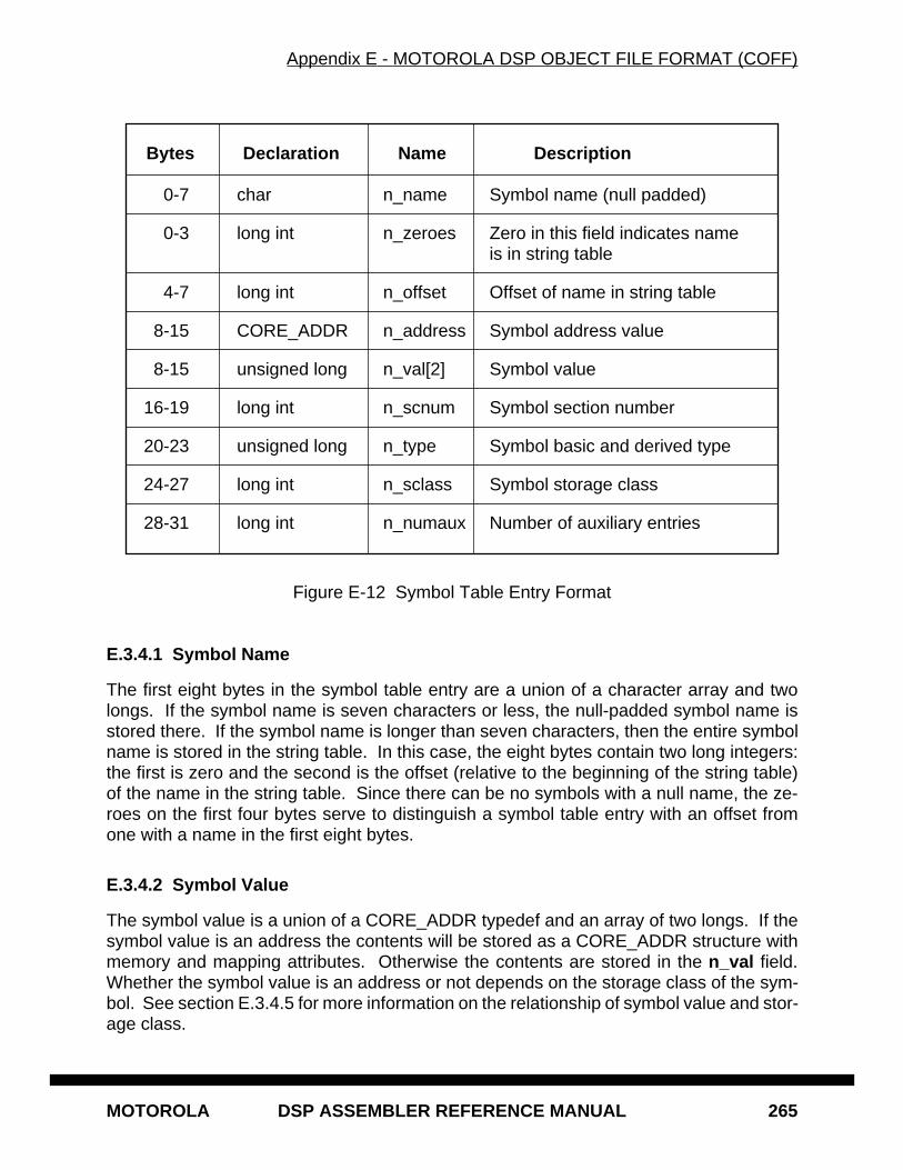
Appendix E - MOTOROLA DSP OBJECT FILE FORMAT (COFF)
MOTOROLA DSP ASSEMBLER REFERENCE MANUAL 265
Figure E-12 Symbol Table Entry Format
E.3.4.1 Symbol Name
The first eight bytes in the symbol table entry are a union of a character array and twolongs. If the symbol name is seven characters or less, the null-padded symbol name isstored there. If the symbol name is longer than seven characters, then the entire symbolname is stored in the string table. In this case, the eight bytes contain two long integers:the first is zero and the second is the offset (relative to the beginning of the string table)of the name in the string table. Since there can be no symbols with a null name, the ze-roes on the first four bytes serve to distinguish a symbol table entry with an offset fromone with a name in the first eight bytes.
E.3.4.2 Symbol Value
The symbol value is a union of a CORE_ADDR typedef and an array of two longs. If thesymbol value is an address the contents will be stored as a CORE_ADDR structure withmemory and mapping attributes. Otherwise the contents are stored in the n_val field.Whether the symbol value is an address or not depends on the storage class of the sym-bol. See section E.3.4.5 for more information on the relationship of symbol value and stor-age class.
Bytes Declaration Name Description
0-7 char n_name Symbol name (null padded)
0-3 long int n_zeroes Zero in this field indicates nameis in string table
4-7 long int n_offset Offset of name in string table
8-15 CORE_ADDR n_address Symbol address value
8-15 unsigned long n_val[2] Symbol value
16-19 long int n_scnum Symbol section number
20-23 unsigned long n_type Symbol basic and derived type
24-27 long int n_sclass Symbol storage class
28-31 long int n_numaux Number of auxiliary entries
Appendix E - MOTOROLA DSP OBJECT FILE FORMAT (COFF)
266 DSP ASSEMBLER REFERENCE MANUAL MOTOROLA
E.3.4.3 Section Number
The section number maps a symbol to its corresponding section in the object file (e.g. thesection in which the symbol is defined). A special section number (-2) marks symbolicdebugging symbols, including structure/union/enumeration tag names, typedefs, and thename of the file. A section number of -1 indicates that the symbol has a value but is notrelocatable. Examples of absolute-valued symbols include automatic and register vari-ables, function arguments, and end-of-structure symbols. A section number of 0 flags arelocatable external symbol that is not defined in the current file. Section numbers greaterthan zero correlate to the ordinal sequence of sections in the object file.
E.3.4.4 Symbol Type
The type field in the symbol table entry contains information about the basic and derivedtype for the symbol. This information is generated by the compiler and assembler only ifthe -G debug option is used. Each symbol has exactly one basic or fundamental type butcan have more than one derived type. The type information is encoded as sets of bits inthe field. Bits 0 through 3 hold one of the fundamental type values given in Figure E-13.
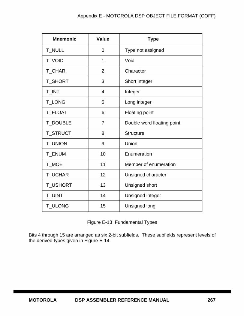
Appendix E - MOTOROLA DSP OBJECT FILE FORMAT (COFF)
MOTOROLA DSP ASSEMBLER REFERENCE MANUAL 267
Figure E-13 Fundamental Types
Bits 4 through 15 are arranged as six 2-bit subfields. These subfields represent levels ofthe derived types given in Figure E-14.
Mnemonic Value Type
T_NULL 0 Type not assigned
T_VOID 1 Void
T_CHAR 2 Character
T_SHORT 3 Short integer
T_INT 4 Integer
T_LONG 5 Long integer
T_FLOAT 6 Floating point
T_DOUBLE 7 Double word floating point
T_STRUCT 8 Structure
T_UNION 9 Union
T_ENUM 10 Enumeration
T_MOE 11 Member of enumeration
T_UCHAR 12 Unsigned character
T_USHORT 13 Unsigned short
T_UINT 14 Unsigned integer
T_ULONG 15 Unsigned long
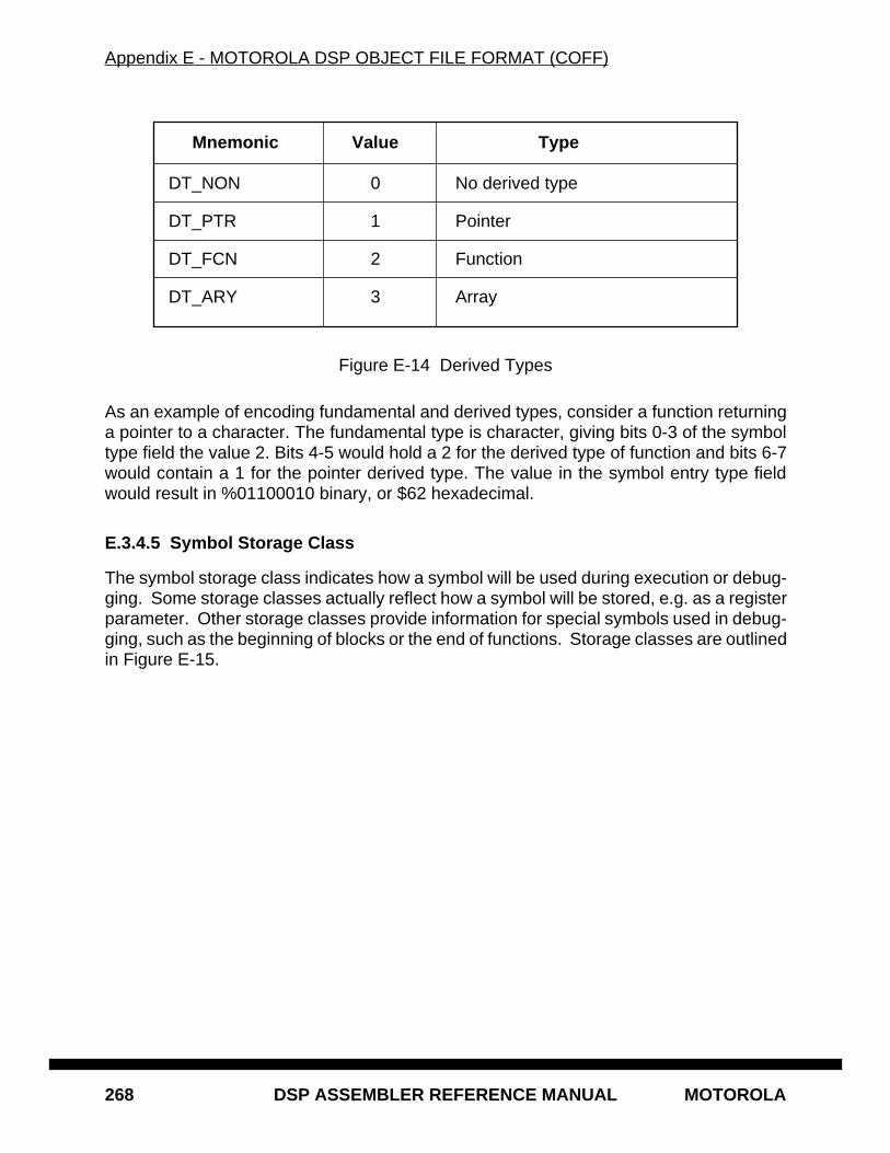
Appendix E - MOTOROLA DSP OBJECT FILE FORMAT (COFF)
268 DSP ASSEMBLER REFERENCE MANUAL MOTOROLA
Figure E-14 Derived Types
As an example of encoding fundamental and derived types, consider a function returninga pointer to a character. The fundamental type is character, giving bits 0-3 of the symboltype field the value 2. Bits 4-5 would hold a 2 for the derived type of function and bits 6-7would contain a 1 for the pointer derived type. The value in the symbol entry type fieldwould result in %01100010 binary, or $62 hexadecimal.
E.3.4.5 Symbol Storage Class
The symbol storage class indicates how a symbol will be used during execution or debug-ging. Some storage classes actually reflect how a symbol will be stored, e.g. as a registerparameter. Other storage classes provide information for special symbols used in debug-ging, such as the beginning of blocks or the end of functions. Storage classes are outlinedin Figure E-15.
Mnemonic Value Type
DT_NON 0 No derived type
DT_PTR 1 Pointer
DT_FCN 2 Function
DT_ARY 3 Array
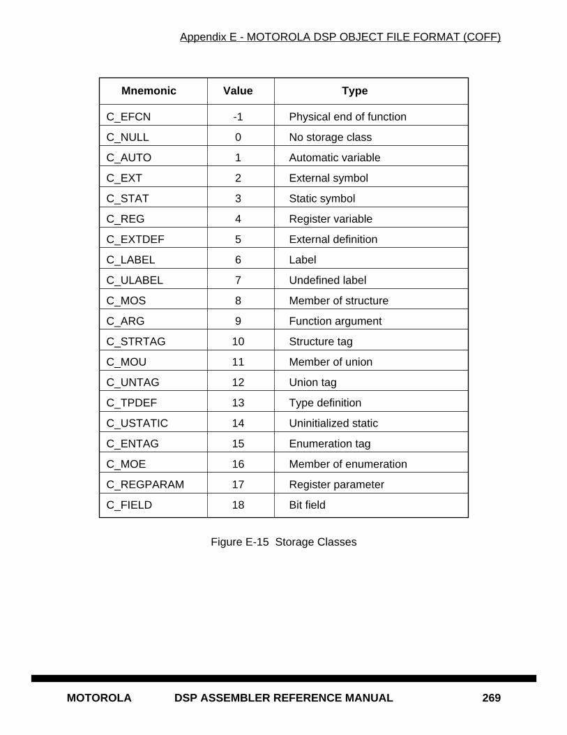
Appendix E - MOTOROLA DSP OBJECT FILE FORMAT (COFF)
MOTOROLA DSP ASSEMBLER REFERENCE MANUAL 269
Figure E-15 Storage Classes
Mnemonic Value Type
C_EFCN -1 Physical end of function
C_NULL 0 No storage class
C_AUTO 1 Automatic variable
C_EXT 2 External symbol
C_STAT 3 Static symbol
C_REG 4 Register variable
C_EXTDEF 5 External definition
C_LABEL 6 Label
C_ULABEL 7 Undefined label
C_MOS 8 Member of structure
C_ARG 9 Function argument
C_STRTAG 10 Structure tag
C_MOU 11 Member of union
C_UNTAG 12 Union tag
C_TPDEF 13 Type definition
C_USTATIC 14 Uninitialized static
C_ENTAG 15 Enumeration tag
C_MOE 16 Member of enumeration
C_REGPARAM 17 Register parameter
C_FIELD 18 Bit field
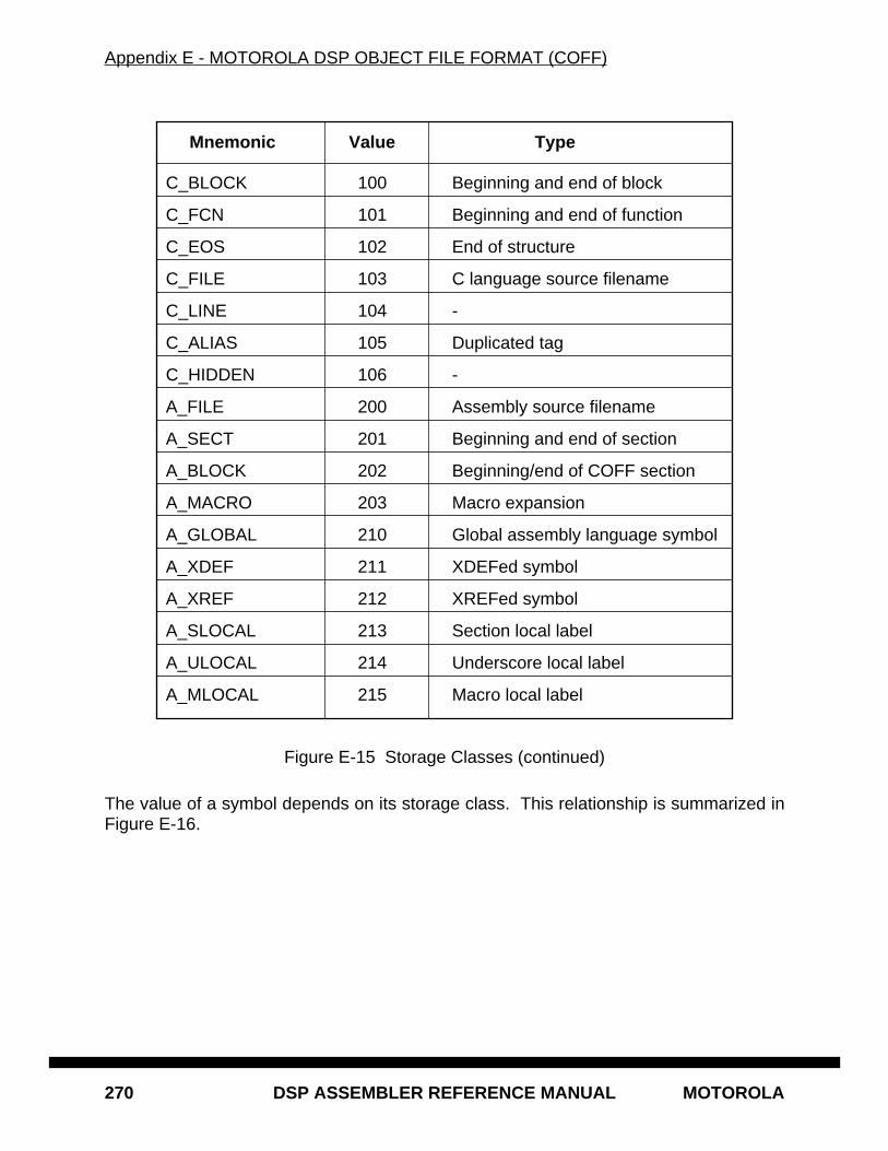
Appendix E - MOTOROLA DSP OBJECT FILE FORMAT (COFF)
270 DSP ASSEMBLER REFERENCE MANUAL MOTOROLA
Figure E-15 Storage Classes (continued)
The value of a symbol depends on its storage class. This relationship is summarized inFigure E-16.
Mnemonic Value Type
C_BLOCK 100 Beginning and end of block
C_FCN 101 Beginning and end of function
C_EOS 102 End of structure
C_FILE 103 C language source filename
C_LINE 104 -
C_ALIAS 105 Duplicated tag
C_HIDDEN 106 -
A_FILE 200 Assembly source filename
A_SECT 201 Beginning and end of section
A_BLOCK 202 Beginning/end of COFF section
A_MACRO 203 Macro expansion
A_GLOBAL 210 Global assembly language symbol
A_XDEF 211 XDEFed symbol
A_XREF 212 XREFed symbol
A_SLOCAL 213 Section local label
A_ULOCAL 214 Underscore local label
A_MLOCAL 215 Macro local label
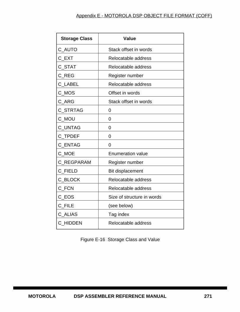
Appendix E - MOTOROLA DSP OBJECT FILE FORMAT (COFF)
MOTOROLA DSP ASSEMBLER REFERENCE MANUAL 271
Figure E-16 Storage Class and Value
Storage Class Value
C_AUTO Stack offset in words
C_EXT Relocatable address
C_STAT Relocatable address
C_REG Register number
C_LABEL Relocatable address
C_MOS Offset in words
C_ARG Stack offset in words
C_STRTAG 0
C_MOU 0
C_UNTAG 0
C_TPDEF 0
C_ENTAG 0
C_MOE Enumeration value
C_REGPARAM Register number
C_FIELD Bit displacement
C_BLOCK Relocatable address
C_FCN Relocatable address
C_EOS Size of structure in words
C_FILE (see below)
C_ALIAS Tag index
C_HIDDEN Relocatable address
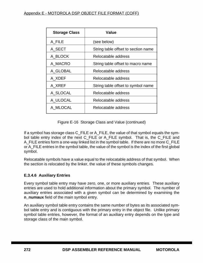
Appendix E - MOTOROLA DSP OBJECT FILE FORMAT (COFF)
272 DSP ASSEMBLER REFERENCE MANUAL MOTOROLA
Figure E-16 Storage Class and Value (continued)
If a symbol has storage class C_FILE or A_FILE, the value of that symbol equals the sym-bol table entry index of the next C_FILE or A_FILE symbol. That is, the C_FILE andA_FILE entries form a one-way linked list in the symbol table. If there are no more C_FILEor A_FILE entries in the symbol table, the value of the symbol is the index of the first globalsymbol.
Relocatable symbols have a value equal to the relocatable address of that symbol. Whenthe section is relocated by the linker, the value of these symbols changes.
E.3.4.6 Auxiliary Entries
Every symbol table entry may have zero, one, or more auxiliary entries. These auxiliaryentries are used to hold additional information about the primary symbol. The number ofauxiliary entries associated with a given symbol can be determined by examining then_numaux field of the main symbol entry.
An auxiliary symbol table entry contains the same number of bytes as its associated sym-bol table entry and is contiguous with the primary entry in the object file. Unlike primarysymbol table entries, however, the format of an auxiliary entry depends on the type andstorage class of the main symbol.
Storage Class Value
A_FILE (see below)
A_SECT String table offset to section name
A_BLOCK Relocatable address
A_MACRO String table offset to macro name
A_GLOBAL Relocatable address
A_XDEF Relocatable address
A_XREF String table offset to symbol name
A_SLOCAL Relocatable address
A_ULOCAL Relocatable address
A_MLOCAL Relocatable address
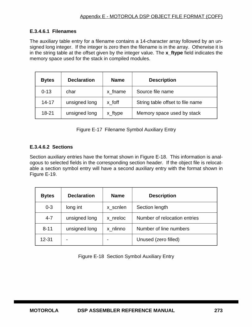
Appendix E - MOTOROLA DSP OBJECT FILE FORMAT (COFF)
MOTOROLA DSP ASSEMBLER REFERENCE MANUAL 273
E.3.4.6.1 Filenames
The auxiliary table entry for a filename contains a 14-character array followed by an un-signed long integer. If the integer is zero then the filename is in the array. Otherwise it isin the string table at the offset given by the integer value. The x_ftype field indicates thememory space used for the stack in compiled modules.
Figure E-17 Filename Symbol Auxiliary Entry
E.3.4.6.2 Sections
Section auxiliary entries have the format shown in Figure E-18. This information is anal-ogous to selected fields in the corresponding section header. If the object file is relocat-able a section symbol entry will have a second auxiliary entry with the format shown inFigure E-19.
Figure E-18 Section Symbol Auxiliary Entry
Bytes Declaration Name Description
0-13 char x_fname Source file name
14-17 unsigned long x_foff String table offset to file name
18-21 unsigned long x_ftype Memory space used by stack
Bytes Declaration Name Description
0-3 long int x_scnlen Section length
4-7 unsigned long x_nreloc Number of relocation entries
8-11 unsigned long x_nlinno Number of line numbers
12-31 - - Unused (zero filled)
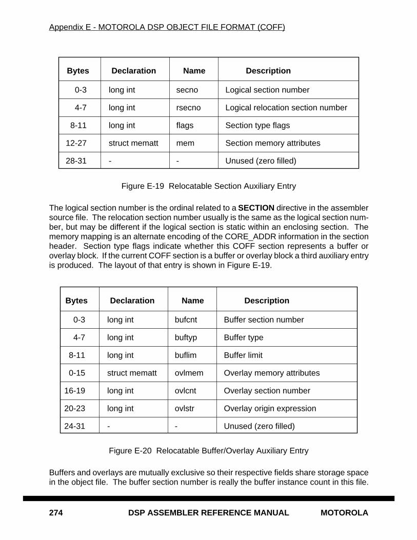
Appendix E - MOTOROLA DSP OBJECT FILE FORMAT (COFF)
274 DSP ASSEMBLER REFERENCE MANUAL MOTOROLA
Figure E-19 Relocatable Section Auxiliary Entry
The logical section number is the ordinal related to a SECTION directive in the assemblersource file. The relocation section number usually is the same as the logical section num-ber, but may be different if the logical section is static within an enclosing section. Thememory mapping is an alternate encoding of the CORE_ADDR information in the sectionheader. Section type flags indicate whether this COFF section represents a buffer oroverlay block. If the current COFF section is a buffer or overlay block a third auxiliary entryis produced. The layout of that entry is shown in Figure E-19.
Figure E-20 Relocatable Buffer/Overlay Auxiliary Entry
Buffers and overlays are mutually exclusive so their respective fields share storage spacein the object file. The buffer section number is really the buffer instance count in this file.
Bytes Declaration Name Description
0-3 long int secno Logical section number
4-7 long int rsecno Logical relocation section number
8-11 long int flags Section type flags
12-27 struct mematt mem Section memory attributes
28-31 - - Unused (zero filled)
Bytes Declaration Name Description
0-3 long int bufcnt Buffer section number
4-7 long int buftyp Buffer type
8-11 long int buflim Buffer limit
0-15 struct mematt ovlmem Overlay memory attributes
16-19 long int ovlcnt Overlay section number
20-23 long int ovlstr Overlay origin expression
24-31 - - Unused (zero filled)
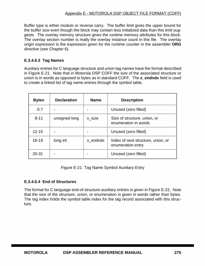
Appendix E - MOTOROLA DSP OBJECT FILE FORMAT (COFF)
MOTOROLA DSP ASSEMBLER REFERENCE MANUAL 275
Buffer type is either modulo or reverse carry. The buffer limit gives the upper bound forthe buffer size even though the block may contain less initialized data than this limit sug-gests. The overlay memory structure gives the runtime memory attributes for this block.The overlay section number is really the overlay instance count in this file. The overlayorigin expression is the expression given for the runtime counter in the assembler ORGdirective (see Chapter 6).
E.3.4.6.3 Tag Names
Auxiliary entries for C language structure and union tag names have the format describedin Figure E-21. Note that in Motorola DSP COFF the size of the associated structure orunion is in words as opposed to bytes as in standard COFF. The x_endndx field is usedto create a linked list of tag name entries through the symbol table.
Figure E-21 Tag Name Symbol Auxiliary Entry
E.3.4.6.4 End of Structures
The format for C language end-of-structure auxiliary entries is given in Figure E-22. Notethat the size of the structure, union, or enumeration is given in words rather than bytes.The tag index holds the symbol table index for the tag record associated with this struc-ture.
Bytes Declaration Name Description
0-7 - - Unused (zero filled)
8-11 unsigned long x_size Size of structure, union, orenumeration in words
12-15 - - Unused (zero filled)
16-19 long int x_endndx Index of next structure, union, orenumeration entry
20-31 - - Unused (zero filled)
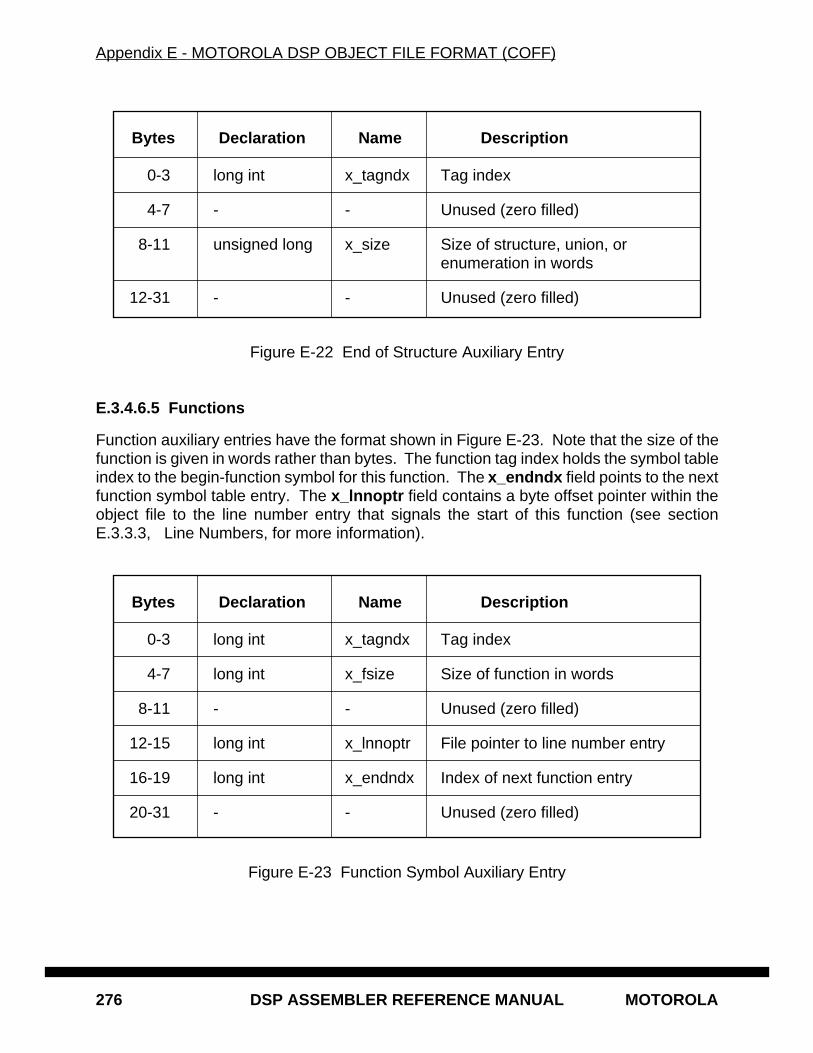
Appendix E - MOTOROLA DSP OBJECT FILE FORMAT (COFF)
276 DSP ASSEMBLER REFERENCE MANUAL MOTOROLA
Figure E-22 End of Structure Auxiliary Entry
E.3.4.6.5 Functions
Function auxiliary entries have the format shown in Figure E-23. Note that the size of thefunction is given in words rather than bytes. The function tag index holds the symbol tableindex to the begin-function symbol for this function. The x_endndx field points to the nextfunction symbol table entry. The x_lnnoptr field contains a byte offset pointer within theobject file to the line number entry that signals the start of this function (see sectionE.3.3.3, Line Numbers, for more information).
Figure E-23 Function Symbol Auxiliary Entry
Bytes Declaration Name Description
0-3 long int x_tagndx Tag index
4-7 - - Unused (zero filled)
8-11 unsigned long x_size Size of structure, union, orenumeration in words
12-31 - - Unused (zero filled)
Bytes Declaration Name Description
0-3 long int x_tagndx Tag index
4-7 long int x_fsize Size of function in words
8-11 - - Unused (zero filled)
12-15 long int x_lnnoptr File pointer to line number entry
16-19 long int x_endndx Index of next function entry
20-31 - - Unused (zero filled)

Appendix E - MOTOROLA DSP OBJECT FILE FORMAT (COFF)
MOTOROLA DSP ASSEMBLER REFERENCE MANUAL 277
E.3.4.6.6 Arrays
The format for C language array auxiliary entries is given in Figure E-24. The tag indexcontains the offset to the next array symbol in the symbol table. The line number fieldgives the source file line number for the array declaration.
Figure E-24 Array Symbol Auxiliary Entry
E.3.4.6.7 End of Blocks and Functions
The format for C language symbol entries for the end of blocks and functions is given inFigure E-25. Only the source file line number for the end of the block or function is stored.
Figure E-25 End of Block or Function Auxiliary Entry
Bytes Declaration Name Description
0-3 long int x_tagndx Tag index
4-7 unsigned long x_lnno Line number of array declaration
8-11 unsigned long x_size Size of array
12-15 unsigned long x_dimen[0] First array dimension
16-19 unsigned long x_dimen[1] Second array dimension
20-23 unsigned long x_dimen[2] Third array dimension
24-27 unsigned long x_dimen[3] Fourth array dimension
28-31 - - Unused (zero filled)
Bytes Declaration Name Description
0-3 - - Unused (zero filled)
4-7 unsigned long x_lnno Source file line number
8-31 - - Unused (zero filled)
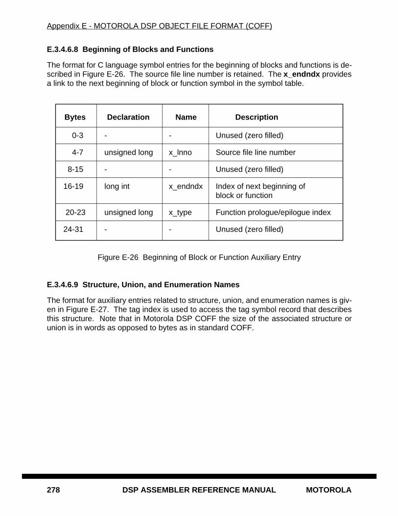
Appendix E - MOTOROLA DSP OBJECT FILE FORMAT (COFF)
278 DSP ASSEMBLER REFERENCE MANUAL MOTOROLA
E.3.4.6.8 Beginning of Blocks and Functions
The format for C language symbol entries for the beginning of blocks and functions is de-scribed in Figure E-26. The source file line number is retained. The x_endndx providesa link to the next beginning of block or function symbol in the symbol table.
Figure E-26 Beginning of Block or Function Auxiliary Entry
E.3.4.6.9 Structure, Union, and Enumeration Names
The format for auxiliary entries related to structure, union, and enumeration names is giv-en in Figure E-27. The tag index is used to access the tag symbol record that describesthis structure. Note that in Motorola DSP COFF the size of the associated structure orunion is in words as opposed to bytes as in standard COFF.
Bytes Declaration Name Description
0-3 - - Unused (zero filled)
4-7 unsigned long x_lnno Source file line number
8-15 - - Unused (zero filled)
16-19 long int x_endndx Index of next beginning ofblock or function
20-23 unsigned long x_type Function prologue/epilogue index
24-31 - - Unused (zero filled)
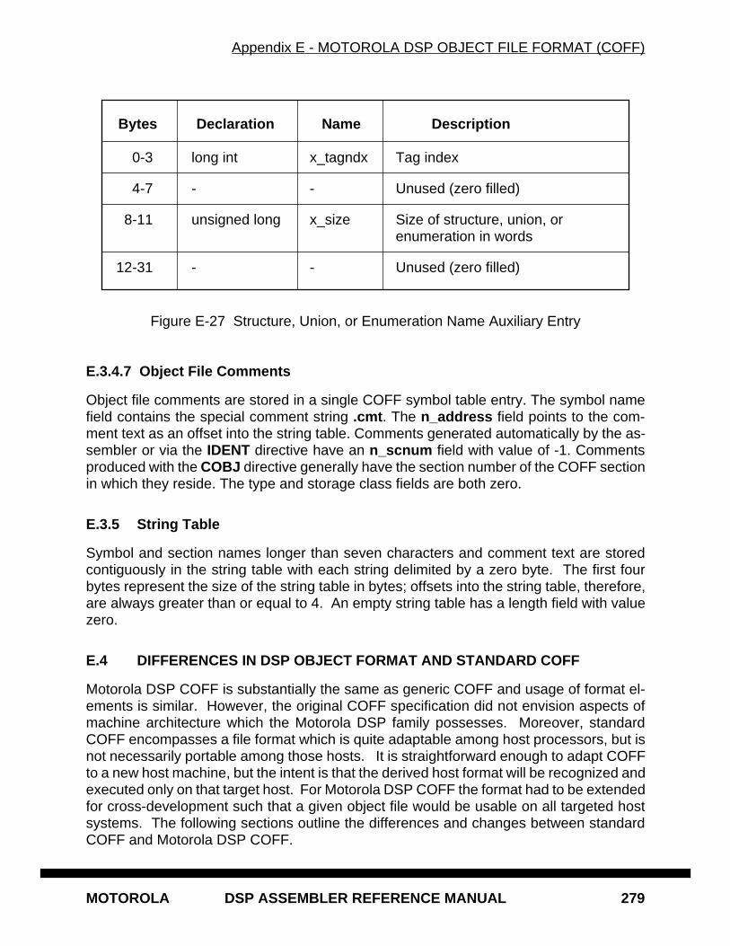
Appendix E - MOTOROLA DSP OBJECT FILE FORMAT (COFF)
MOTOROLA DSP ASSEMBLER REFERENCE MANUAL 279
Figure E-27 Structure, Union, or Enumeration Name Auxiliary Entry
E.3.4.7 Object File Comments
Object file comments are stored in a single COFF symbol table entry. The symbol namefield contains the special comment string .cmt . The n_address field points to the com-ment text as an offset into the string table. Comments generated automatically by the as-sembler or via the IDENT directive have an n_scnum field with value of -1. Commentsproduced with the COBJ directive generally have the section number of the COFF sectionin which they reside. The type and storage class fields are both zero.
E.3.5 String Table
Symbol and section names longer than seven characters and comment text are storedcontiguously in the string table with each string delimited by a zero byte. The first fourbytes represent the size of the string table in bytes; offsets into the string table, therefore,are always greater than or equal to 4. An empty string table has a length field with valuezero.
E.4 DIFFERENCES IN DSP OBJECT FORMAT AND STANDARD COFF
Motorola DSP COFF is substantially the same as generic COFF and usage of format el-ements is similar. However, the original COFF specification did not envision aspects ofmachine architecture which the Motorola DSP family possesses. Moreover, standardCOFF encompasses a file format which is quite adaptable among host processors, but isnot necessarily portable among those hosts. It is straightforward enough to adapt COFFto a new host machine, but the intent is that the derived host format will be recognized andexecuted only on that target host. For Motorola DSP COFF the format had to be extendedfor cross-development such that a given object file would be usable on all targeted hostsystems. The following sections outline the differences and changes between standardCOFF and Motorola DSP COFF.
Bytes Declaration Name Description
0-3 long int x_tagndx Tag index
4-7 - - Unused (zero filled)
8-11 unsigned long x_size Size of structure, union, orenumeration in words
12-31 - - Unused (zero filled)
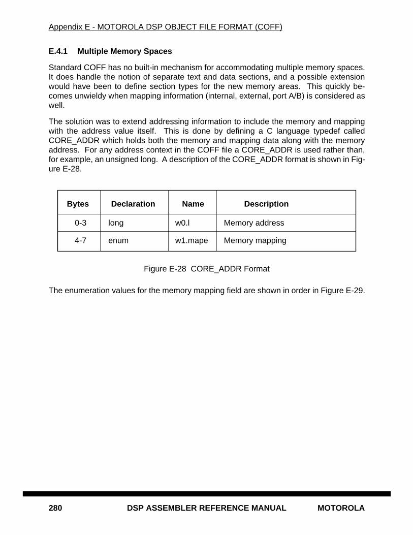
Appendix E - MOTOROLA DSP OBJECT FILE FORMAT (COFF)
280 DSP ASSEMBLER REFERENCE MANUAL MOTOROLA
E.4.1 Multiple Memory Spaces
Standard COFF has no built-in mechanism for accommodating multiple memory spaces.It does handle the notion of separate text and data sections, and a possible extensionwould have been to define section types for the new memory areas. This quickly be-comes unwieldy when mapping information (internal, external, port A/B) is considered aswell.
The solution was to extend addressing information to include the memory and mappingwith the address value itself. This is done by defining a C language typedef calledCORE_ADDR which holds both the memory and mapping data along with the memoryaddress. For any address context in the COFF file a CORE_ADDR is used rather than,for example, an unsigned long. A description of the CORE_ADDR format is shown in Fig-ure E-28.
Figure E-28 CORE_ADDR Format
The enumeration values for the memory mapping field are shown in order in Figure E-29.
Bytes Declaration Name Description
0-3 long w0.l Memory address
4-7 enum w1.mape Memory mapping

Appendix E - MOTOROLA DSP OBJECT FILE FORMAT (COFF)
MOTOROLA DSP ASSEMBLER REFERENCE MANUAL 281
Figure E-29 Memory Mapping Enumerations
E.4.2 Object File Transportability
There are many different structure definitions in the COFF specification. These definitionsconsist of fields comprised of varying C data types. These data types are recognized byany reasonable C compiler, but their characteristics and sizes may change from machineto machine. This is acceptable if the COFF files are to be used only on a particular ma-chine architecture. But if COFF files are produced on one machine to be used on anotherseveral problems may arise. One is that since the data fields can vary in size there couldbe alignment problems when accessing structures or individual fields. Another issue isbyte ordering between machines. Given an arbitrary byte stream, some machines storethe bytes in a word starting at the least significant bit (LSB) end of the word, while othersstore bytes starting at the most significant bit (MSB) end of the word.
Mnemonic Value Mnemonic Value
memory_map_p 0 memory_map_xa 16
memory_map_x 1 memory_map_xb 17
memory_map_y 2 memory_map_xe 18
memory_map_l 3 memory_map_xi 19
memory_map_none 4 memory_map_xr 20
memory_map_laa 5 memory_map_ya 21
memory_map_lab 6 memory_map_yb 22
memory_map_lba 7 memory_map_ye 23
memory_map_lbb 8 memory_map_yi 24
memory_map_le 9 memory_map_yr 25
memory_map_li 10 memory_map_pt 26
memory_map_pa 11 memory_map_pf 27
memory_map_pb 12 memory_map_emi 28
memory_map_pe 13 memory_map_e0-63 29-92
memory_map_pi 14 memory_map_error 666666
memory_map_pr 15
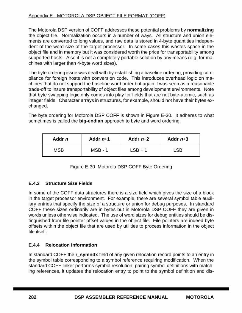
Appendix E - MOTOROLA DSP OBJECT FILE FORMAT (COFF)
282 DSP ASSEMBLER REFERENCE MANUAL MOTOROLA
The Motorola DSP version of COFF addresses these potential problems by normalizingthe object file. Normalization occurs in a number of ways. All structure and union ele-ments are converted to long values, and raw data is stored in 4-byte quantities indepen-dent of the word size of the target processor. In some cases this wastes space in theobject file and in memory but it was considered worth the price for transportability amongsupported hosts. Also it is not a completely portable solution by any means (e.g. for ma-chines with larger than 4-byte word sizes).
The byte ordering issue was dealt with by establishing a baseline ordering, providing com-pliance for foreign hosts with conversion code. This introduces overhead logic on ma-chines that do not support the baseline word order but again it was seen as a reasonabletrade-off to insure transportability of object files among development environments. Notethat byte swapping logic only comes into play for fields that are not byte-atomic, such asinteger fields. Character arrays in structures, for example, should not have their bytes ex-changed.
The byte ordering for Motorola DSP COFF is shown in Figure E-30. It adheres to whatsometimes is called the big-endian approach to byte and word ordering.
Figure E-30 Motorola DSP COFF Byte Ordering
E.4.3 Structure Size Fields
In some of the COFF data structures there is a size field which gives the size of a blockin the target processor environment. For example, there are several symbol table auxil-iary entries that specify the size of a structure or union for debug purposes. In standardCOFF these sizes ordinarily are in bytes but in Motorola DSP COFF they are given inwords unless otherwise indicated. The use of word sizes for debug entities should be dis-tinguished from file pointer offset values in the object file. File pointers are indeed byteoffsets within the object file that are used by utilities to process information in the objectfile itself.
E.4.4 Relocation Information
In standard COFF the r_symndx field of any given relocation record points to an entry inthe symbol table corresponding to a symbol reference requiring modification. When thestandard COFF linker performs symbol resolution, pairing symbol definitions with match-ing references, it updates the relocation entry to point to the symbol definition and dis-
Addr n Addr n+1 Addr n+2 Addr n+3
MSB MSB - 1 LSB + 1 LSB
Appendix E - MOTOROLA DSP OBJECT FILE FORMAT (COFF)
MOTOROLA DSP ASSEMBLER REFERENCE MANUAL 283
cards the reference symbol. When the relocation entries are processed, the resolvedsymbol value is used to modify the raw data indicated by the relocation entry at r_vaddr .
In Motorola DSP COFF r_symndx is an offset into the string table which points to a relo-cation expression. The linker interprets this expression and updates the entire word atr_vaddr with the result of the expression evaluation. The relocation type is always zero.See section E.5, OBJECT FILE DATA EXPRESSION FORMAT for more information onrelocation expressions.
E.4.5 Block Data Sections
Generic COFF does not make allowance for a block data section. A block data sectionresults from use of the assembler BSC directive, where a large block of memory is initial-ized with a single value. Block data sections are handled in Motorola DSP COFF by mak-ing special use of the section s_vaddr field and adding an informative flag.
In most cases the section virtual address is the same as the physical address. However,for block data sections in Motorola DSP object files the virtual address field holds the re-peat count for the single raw data value associated with the section. For example, if theassembly language source file included a directive of the form BSC $400,$FFFF thes_vaddr field would contain the value $400, the s_size field would be 1 (or 2 if in L mem-ory), and the single raw data word associated with the section would be $FFFF. In addi-tion, the STYP_BLOCK flag is set in the section s_flags field.
E.4.6 Other Extensions
If the object file is relocatable there are extra structures which the assembler and linkergenerate to support special constructs such as logical sections, buffers, and overlays.The optional link file header contains information which the linker requires; it is describedin section E.3.2. Every symbol table entry for a section in a relocatable file has an extraauxiliary entry described in section E.3.4.6.2.
One special DSP COFF structure not documented elsewhere is the comment symbol. Acomment symbol table entry is emitted either indirectly via the assembler IDENT directiveor directly with the COBJ directive (see Chapter 6). A comment symbol table entry maybe identified by a symbol name of .cmt and a type and storage class of zero. The valuefield of a comment symbol holds the offset into the string table of the comment text. Thesection number for a comment symbol produced with the IDENT directive is always -1.Comment symbols generated with the COBJ directive have the section number of thesection where the COBJ directive appears in the source file. Comment symbols have noauxiliary entry.
E.5 OBJECT FILE DATA EXPRESSION FORMAT
Object file data expressions are used in data relocation records to represent values to beloaded into memory. An expression is a combination of symbols, constants, operators,

Appendix E - MOTOROLA DSP OBJECT FILE FORMAT (COFF)
284 DSP ASSEMBLER REFERENCE MANUAL MOTOROLA
and parentheses. Expressions may contain user-defined labels, integers, floating pointnumbers, or literal strings. An object file data expression generally follows the guidelinesof assembler expressions, except that functions are not supported (e.g. they must beevaluated at assembly time), and operators are provided for linker-specific operations. Al-so, floating point terms found in these expressions are converted to binary values.
E.5.1 Data Expression Generation
Link file data expressions are generated when external or relocatable operands are en-countered during assembly or incremental link processing. In most cases the operand ex-pression is copied verbatim from the source and embellished with link evaluation controlconstructs. For example, consider the source line below:
MOVE #FOO,R0
The DSP96000 assembler produces the following encoding for this line in the object file:
$3A8D2000 {FOO}@0#0
Since the symbol FOO is not known to the assembler it generates a two-word instructionand places a relocation reference to the expression in the position of the second instruc-tion word. The braces ({ } ) indicate that this is a user expression that should adhere tocertain integrity constraints such as those governing absolute and relative terms. Other-wise the braces are treated much like parentheses. The at sign (@) is a binary operatorindicating the memory space of the left operand by the right. The pound sign (#) is a binaryoperator signifying the size in bits of the left operand by the right. More information onthese special operators and their operands is given below.
Here is another example of data expression generation:
JCLR #1,X:LOC,LABEL
For this conditional jump the assembler produces the following object file code:
(($02A00481&~(~(~0<<8)<<12))I(({LOC}@1#8&~(~0<<8))<<12)) {LABEL}@0#0
The first expression is evaluated such that the relative address LOC, resolved at link time,is shifted and masked into the middle eight bits of the base instruction word ($02A00481).The expression could have been more complex if the bit number was an external refer-ence. The relative value of the symbol LABEL occupies the second instruction word.
E.5.2 Data Expression Interpretation
Object file data expressions are similar to standard assembler expressions which gener-ally follow the rules of algebra and boolean arithmetic. They are written using infix nota-tion in conjunction with unary and binary operators and parentheses. There are alsoextensions to the usual set of assembler arithmetic and grouping operators. These arecontrol constructs that assist the linker in determining the size, type, and characteristicsof an expression operand.
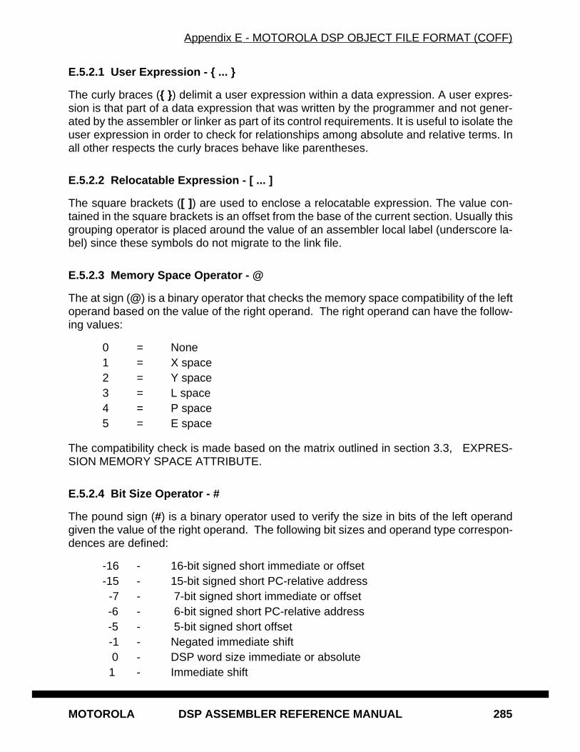
Appendix E - MOTOROLA DSP OBJECT FILE FORMAT (COFF)
MOTOROLA DSP ASSEMBLER REFERENCE MANUAL 285
E.5.2.1 User Expression - { ... }
The curly braces ({ } ) delimit a user expression within a data expression. A user expres-sion is that part of a data expression that was written by the programmer and not gener-ated by the assembler or linker as part of its control requirements. It is useful to isolate theuser expression in order to check for relationships among absolute and relative terms. Inall other respects the curly braces behave like parentheses.
E.5.2.2 Relocatable Expression - [ ... ]
The square brackets ([ ] ) are used to enclose a relocatable expression. The value con-tained in the square brackets is an offset from the base of the current section. Usually thisgrouping operator is placed around the value of an assembler local label (underscore la-bel) since these symbols do not migrate to the link file.
E.5.2.3 Memory Space Operator - @
The at sign (@) is a binary operator that checks the memory space compatibility of the leftoperand based on the value of the right operand. The right operand can have the follow-ing values:
0 = None1 = X space2 = Y space3 = L space4 = P space5 = E space
The compatibility check is made based on the matrix outlined in section 3.3, EXPRES-SION MEMORY SPACE ATTRIBUTE.
E.5.2.4 Bit Size Operator - #
The pound sign (#) is a binary operator used to verify the size in bits of the left operandgiven the value of the right operand. The following bit sizes and operand type correspon-dences are defined:
-16 - 16-bit signed short immediate or offset-15 - 15-bit signed short PC-relative address -7 - 7-bit signed short immediate or offset-6 - 6-bit signed short PC-relative address-5 - 5-bit signed short offset
-1 - Negated immediate shift 0 - DSP word size immediate or absolute 1 - Immediate shift
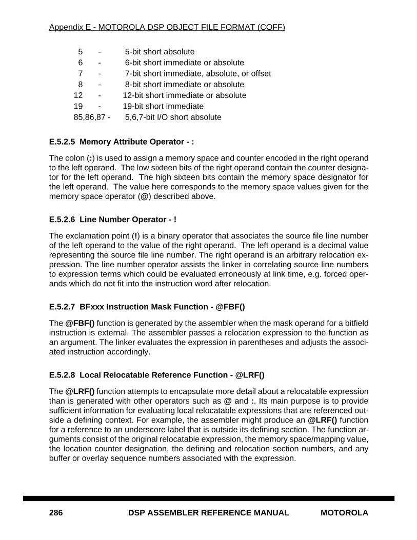
Appendix E - MOTOROLA DSP OBJECT FILE FORMAT (COFF)
286 DSP ASSEMBLER REFERENCE MANUAL MOTOROLA
5 - 5-bit short absolute 6 - 6-bit short immediate or absolute 7 - 7-bit short immediate, absolute, or offset 8 - 8-bit short immediate or absolute12 - 12-bit short immediate or absolute19 - 19-bit short immediate85,86,87 - 5,6,7-bit I/O short absolute
E.5.2.5 Memory Attribute Operator - :
The colon (:) is used to assign a memory space and counter encoded in the right operandto the left operand. The low sixteen bits of the right operand contain the counter designa-tor for the left operand. The high sixteen bits contain the memory space designator forthe left operand. The value here corresponds to the memory space values given for thememory space operator (@) described above.
E.5.2.6 Line Number Operator - !
The exclamation point (!) is a binary operator that associates the source file line numberof the left operand to the value of the right operand. The left operand is a decimal valuerepresenting the source file line number. The right operand is an arbitrary relocation ex-pression. The line number operator assists the linker in correlating source line numbersto expression terms which could be evaluated erroneously at link time, e.g. forced oper-ands which do not fit into the instruction word after relocation.
E.5.2.7 BFxxx Instruction Mask Function - @FBF()
The @FBF() function is generated by the assembler when the mask operand for a bitfieldinstruction is external. The assembler passes a relocation expression to the function asan argument. The linker evaluates the expression in parentheses and adjusts the associ-ated instruction accordingly.
E.5.2.8 Local Relocatable Reference Function - @LRF()
The @LRF() function attempts to encapsulate more detail about a relocatable expressionthan is generated with other operators such as @ and :. Its main purpose is to providesufficient information for evaluating local relocatable expressions that are referenced out-side a defining context. For example, the assembler might produce an @LRF() functionfor a reference to an underscore label that is outside its defining section. The function ar-guments consist of the original relocatable expression, the memory space/mapping value,the location counter designation, the defining and relocation section numbers, and anybuffer or overlay sequence numbers associated with the expression.
Appendix E - MOTOROLA DSP OBJECT FILE FORMAT (COFF)
MOTOROLA DSP ASSEMBLER REFERENCE MANUAL 287
E.5.2.9 Alternate Encoding Function - @ENC()
The @ENC() provides two encoding expressions for the same instruction. This is usefulin cases where the unknown value of an external operand can affect which expression isused for the final encoding. The function takes four arguments. The first argument to thefunction is the external operand expression. The second argument is the absolute valuebeyond which the second encoding expression is used over the first. The third argumentis the first encoding expression and the last argument is the second encoding expression.
Appendix E - MOTOROLA DSP OBJECT FILE FORMAT (COFF)
288 DSP ASSEMBLER REFERENCE MANUAL MOTOROLA
MOTOROLA DSP ASSEMBLER REFERENCE MANUAL 289
Appendix FDEVICE-DEPENDENT INFORMATION
F.1 INTRODUCTION
The Motorola DSP assemblers are quite similar in terms of functional capabilities. Virtu-ally every assembler feature is available across all Motorola DSP processor families. Thedevices for which the assemblers generate code, however, differ architecturally. For ex-ample, the DSP56000 is a binary fractional machine with a suitably-oriented register andinstruction set. The DSP96000 is a floating point processor with floating point instructionsand an alternatively-named register set. The following sections describe characteristicsthat vary among Motorola DSPs and how these differences relate to assembler use andoperation.
Appendix F - DEVICE-DEPENDENT INFORMATION
290 DSP ASSEMBLER REFERENCE MANUAL MOTOROLA
F.2 DSP56000 INFORMATION
The Motorola DSP56000 refers to a family of high-speed, low power programmableCMOS processors. The DSP56000 supports 24-bit signed fixed-point fractional arith-metic.
F.2.1 Instruction Set Summary
DSP56000 instructions can be grouped by function into six types:
1. Arithmetic instructions2. Logical instructions3. Bit manipulation instructions4. Loop instructions5. Move instructions6. Program control instructions
F.2.1.1 Arithmetic Instructions
The DSP56000 instructions used for arithmetic operations are:
ABS - Absolute value*ADC - Add long with carry*ADD - Add*ADDL - Shift left then add*ADDR - Shift right then add*ASL - Arithmetic shift accumulator left*ASR - Arithmetic shift accumulator right*CLR - Clear accumulator*CMP - Compare*CMPM - Compare magnitude*DEC - Decrement accumulatorDIV - Divide iterationINC - Increment accumulatorMAC - Signed multiply-accumulate*MACR - Signed multiply-accumulate and round*MPY - Signed multiply*MPYR - Signed multiply and round*NEG - Negate accumulator*NORM - Normalize accumulator iterationRND - Round accumulator*
*Instruction allows parallel data move.
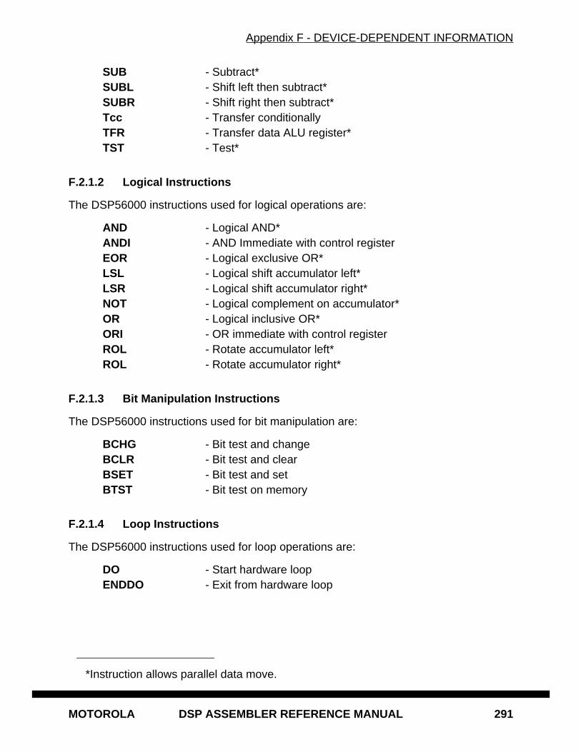
Appendix F - DEVICE-DEPENDENT INFORMATION
MOTOROLA DSP ASSEMBLER REFERENCE MANUAL 291
SUB - Subtract*SUBL - Shift left then subtract*SUBR - Shift right then subtract*Tcc - Transfer conditionallyTFR - Transfer data ALU register*TST - Test*
F.2.1.2 Logical Instructions
The DSP56000 instructions used for logical operations are:
AND - Logical AND*ANDI - AND Immediate with control registerEOR - Logical exclusive OR*LSL - Logical shift accumulator left*LSR - Logical shift accumulator right*NOT - Logical complement on accumulator*OR - Logical inclusive OR*ORI - OR immediate with control registerROL - Rotate accumulator left*ROL - Rotate accumulator right*
F.2.1.3 Bit Manipulation Instructions
The DSP56000 instructions used for bit manipulation are:
BCHG - Bit test and changeBCLR - Bit test and clearBSET - Bit test and setBTST - Bit test on memory
F.2.1.4 Loop Instructions
The DSP56000 instructions used for loop operations are:
DO - Start hardware loopENDDO - Exit from hardware loop
*Instruction allows parallel data move.
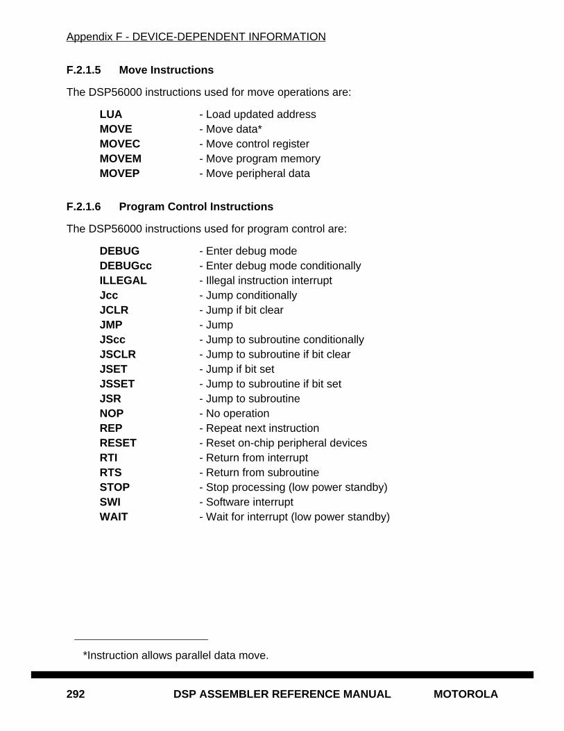
Appendix F - DEVICE-DEPENDENT INFORMATION
292 DSP ASSEMBLER REFERENCE MANUAL MOTOROLA
F.2.1.5 Move Instructions
The DSP56000 instructions used for move operations are:
LUA - Load updated addressMOVE - Move data*MOVEC - Move control registerMOVEM - Move program memoryMOVEP - Move peripheral data
F.2.1.6 Program Control Instructions
The DSP56000 instructions used for program control are:
DEBUG - Enter debug modeDEBUGcc - Enter debug mode conditionallyILLEGAL - Illegal instruction interruptJcc - Jump conditionallyJCLR - Jump if bit clearJMP - JumpJScc - Jump to subroutine conditionallyJSCLR - Jump to subroutine if bit clearJSET - Jump if bit setJSSET - Jump to subroutine if bit setJSR - Jump to subroutineNOP - No operationREP - Repeat next instructionRESET - Reset on-chip peripheral devicesRTI - Return from interruptRTS - Return from subroutineSTOP - Stop processing (low power standby)SWI - Software interruptWAIT - Wait for interrupt (low power standby)
*Instruction allows parallel data move.
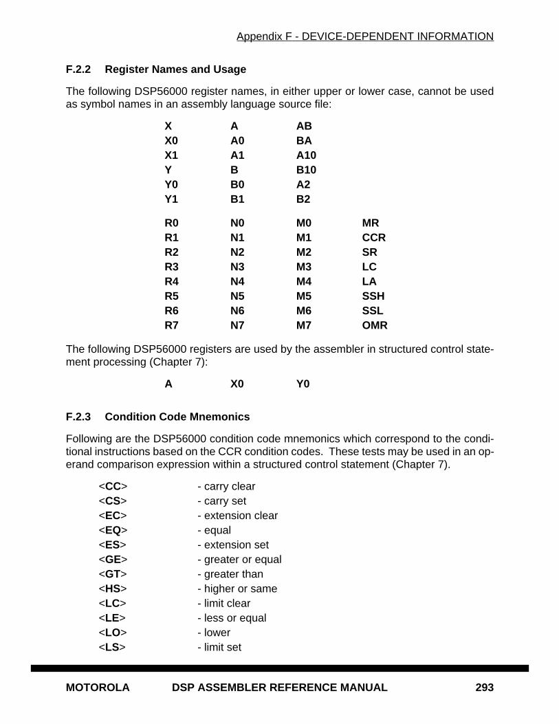
Appendix F - DEVICE-DEPENDENT INFORMATION
MOTOROLA DSP ASSEMBLER REFERENCE MANUAL 293
F.2.2 Register Names and Usage
The following DSP56000 register names, in either upper or lower case, cannot be usedas symbol names in an assembly language source file:
X A ABX0 A0 BAX1 A1 A10Y B B10Y0 B0 A2Y1 B1 B2
R0 N0 M0 MRR1 N1 M1 CCRR2 N2 M2 SRR3 N3 M3 LCR4 N4 M4 LAR5 N5 M5 SSHR6 N6 M6 SSLR7 N7 M7 OMR
The following DSP56000 registers are used by the assembler in structured control state-ment processing (Chapter 7):
A X0 Y0
F.2.3 Condition Code Mnemonics
Following are the DSP56000 condition code mnemonics which correspond to the condi-tional instructions based on the CCR condition codes. These tests may be used in an op-erand comparison expression within a structured control statement (Chapter 7).
<CC> - carry clear<CS> - carry set<EC> - extension clear<EQ> - equal<ES> - extension set<GE> - greater or equal<GT> - greater than<HS> - higher or same<LC> - limit clear<LE> - less or equal<LO> - lower<LS> - limit set
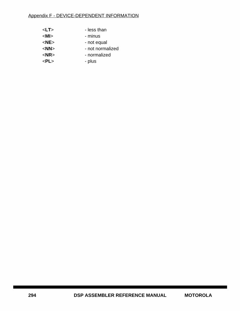
Appendix F - DEVICE-DEPENDENT INFORMATION
294 DSP ASSEMBLER REFERENCE MANUAL MOTOROLA
<LT> - less than<MI> - minus<NE> - not equal<NN> - not normalized<NR> - normalized<PL> - plus
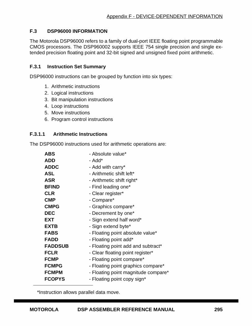
Appendix F - DEVICE-DEPENDENT INFORMATION
MOTOROLA DSP ASSEMBLER REFERENCE MANUAL 295
F.3 DSP96000 INFORMATION
The Motorola DSP96000 refers to a family of dual-port IEEE floating point programmableCMOS processors. The DSP960002 supports IEEE 754 single precision and single ex-tended precision floating point and 32-bit signed and unsigned fixed point arithmetic.
F.3.1 Instruction Set Summary
DSP96000 instructions can be grouped by function into six types:
1. Arithmetic instructions2. Logical instructions3. Bit manipulation instructions4. Loop instructions5. Move instructions6. Program control instructions
F.3.1.1 Arithmetic Instructions
The DSP96000 instructions used for arithmetic operations are:
ABS - Absolute value*ADD - Add*ADDC - Add with carry*ASL - Arithmetic shift left*ASR - Arithmetic shift right*BFIND - Find leading one*CLR - Clear register*CMP - Compare*CMPG - Graphics compare*DEC - Decrement by one*EXT - Sign extend half word*EXTB - Sign extend byte*FABS - Floating point absolute value*FADD - Floating point add*FADDSUB - Floating point add and subtract*FCLR - Clear floating point register*FCMP - Floating point compare*FCMPG - Floating point graphics compare*FCMPM - Floating point magnitude compare*FCOPYS - Floating point copy sign*
*Instruction allows parallel data move.
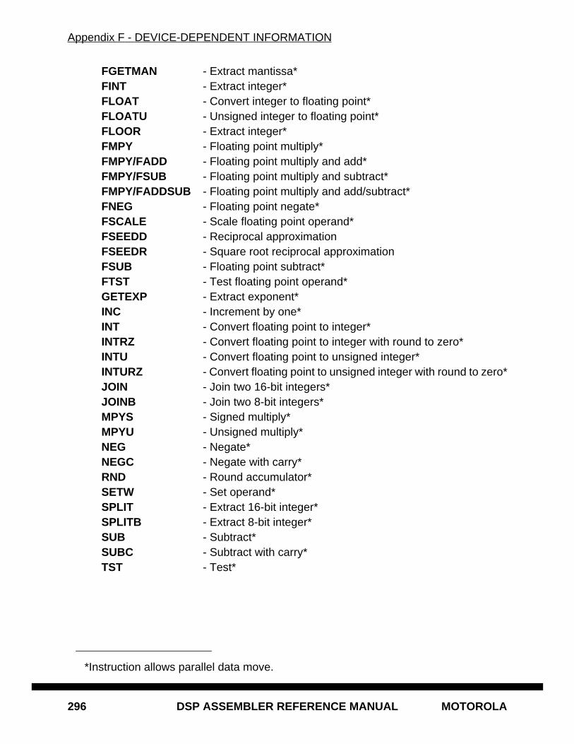
Appendix F - DEVICE-DEPENDENT INFORMATION
296 DSP ASSEMBLER REFERENCE MANUAL MOTOROLA
FGETMAN - Extract mantissa*FINT - Extract integer*FLOAT - Convert integer to floating point*FLOATU - Unsigned integer to floating point*FLOOR - Extract integer*FMPY - Floating point multiply*FMPY/FADD - Floating point multiply and add*FMPY/FSUB - Floating point multiply and subtract*FMPY/FADDSUB - Floating point multiply and add/subtract*FNEG - Floating point negate*FSCALE - Scale floating point operand*FSEEDD - Reciprocal approximationFSEEDR - Square root reciprocal approximationFSUB - Floating point subtract*FTST - Test floating point operand*GETEXP - Extract exponent*INC - Increment by one*INT - Convert floating point to integer*INTRZ - Convert floating point to integer with round to zero*INTU - Convert floating point to unsigned integer*INTURZ - Convert floating point to unsigned integer with round to zero*JOIN - Join two 16-bit integers*JOINB - Join two 8-bit integers*MPYS - Signed multiply*MPYU - Unsigned multiply*NEG - Negate*NEGC - Negate with carry*RND - Round accumulator*SETW - Set operand*SPLIT - Extract 16-bit integer*SPLITB - Extract 8-bit integer*SUB - Subtract*SUBC - Subtract with carry*TST - Test*
*Instruction allows parallel data move.
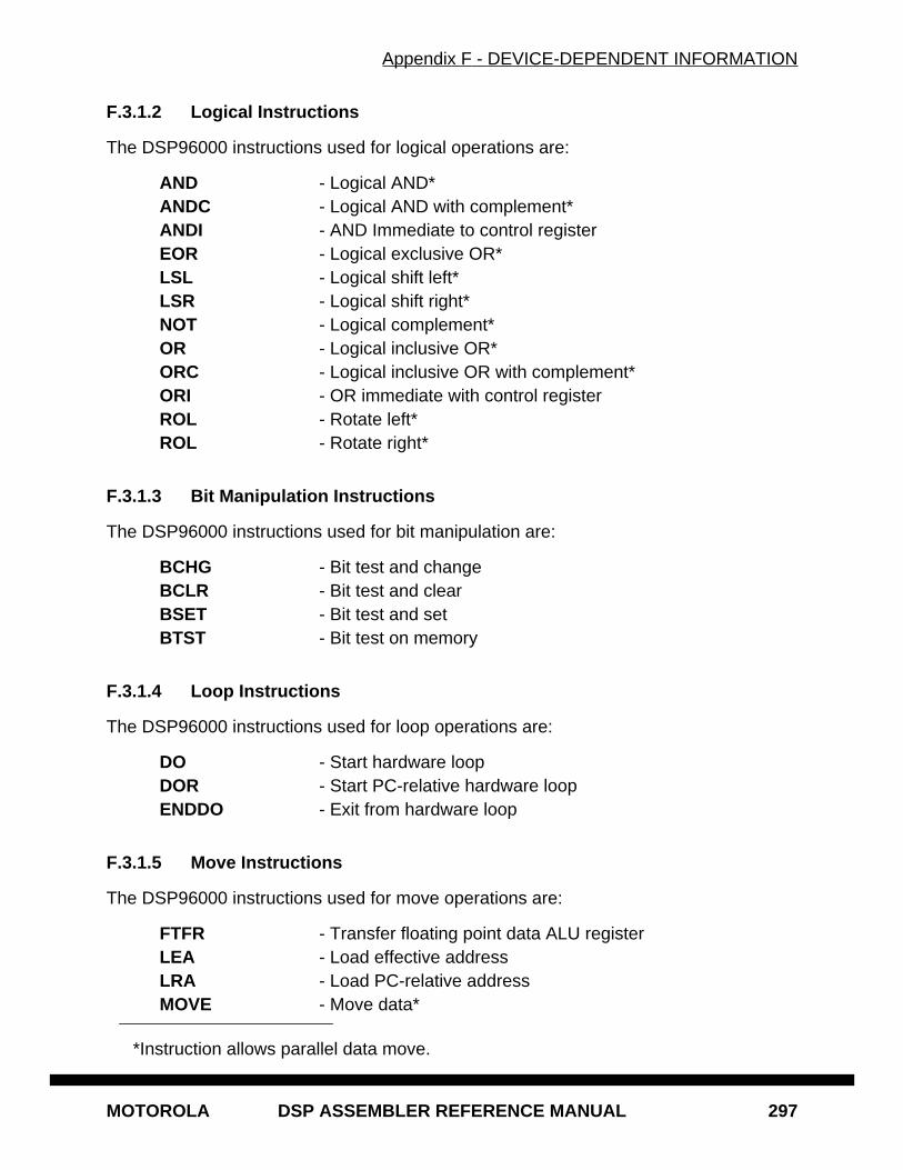
Appendix F - DEVICE-DEPENDENT INFORMATION
MOTOROLA DSP ASSEMBLER REFERENCE MANUAL 297
F.3.1.2 Logical Instructions
The DSP96000 instructions used for logical operations are:
AND - Logical AND*ANDC - Logical AND with complement*ANDI - AND Immediate to control registerEOR - Logical exclusive OR*LSL - Logical shift left*LSR - Logical shift right*NOT - Logical complement*OR - Logical inclusive OR*ORC - Logical inclusive OR with complement*ORI - OR immediate with control registerROL - Rotate left*ROL - Rotate right*
F.3.1.3 Bit Manipulation Instructions
The DSP96000 instructions used for bit manipulation are:
BCHG - Bit test and changeBCLR - Bit test and clearBSET - Bit test and setBTST - Bit test on memory
F.3.1.4 Loop Instructions
The DSP96000 instructions used for loop operations are:
DO - Start hardware loopDOR - Start PC-relative hardware loopENDDO - Exit from hardware loop
F.3.1.5 Move Instructions
The DSP96000 instructions used for move operations are:
FTFR - Transfer floating point data ALU registerLEA - Load effective addressLRA - Load PC-relative addressMOVE - Move data*
*Instruction allows parallel data move.
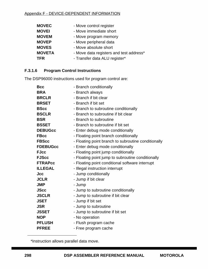
Appendix F - DEVICE-DEPENDENT INFORMATION
298 DSP ASSEMBLER REFERENCE MANUAL MOTOROLA
MOVEC - Move control registerMOVEI - Move immediate shortMOVEM - Move program memoryMOVEP - Move peripheral dataMOVES - Move absolute shortMOVETA - Move data registers and test address*TFR - Transfer data ALU register*
F.3.1.6 Program Control Instructions
The DSP96000 instructions used for program control are:
Bcc - Branch conditionallyBRA - Branch alwaysBRCLR - Branch if bit clearBRSET - Branch if bit setBScc - Branch to subroutine conditionallyBSCLR - Branch to subroutine if bit clearBSR - Branch to subroutineBSSET - Branch to subroutine if bit setDEBUGcc - Enter debug mode conditionallyFBcc - Floating point branch conditionallyFBScc - Floating point branch to subroutine conditionallyFDEBUGcc - Enter debug mode conditionallyFJcc - Floating point jump conditionallyFJScc - Floating point jump to subroutine conditionallyFTRAPcc - Floating point conditional software interruptILLEGAL - Illegal instruction interruptJcc - Jump conditionallyJCLR - Jump if bit clearJMP - JumpJScc - Jump to subroutine conditionallyJSCLR - Jump to subroutine if bit clearJSET - Jump if bit setJSR - Jump to subroutineJSSET - Jump to subroutine if bit setNOP - No operationPFLUSH - Flush program cachePFREE - Free program cache
*Instruction allows parallel data move.
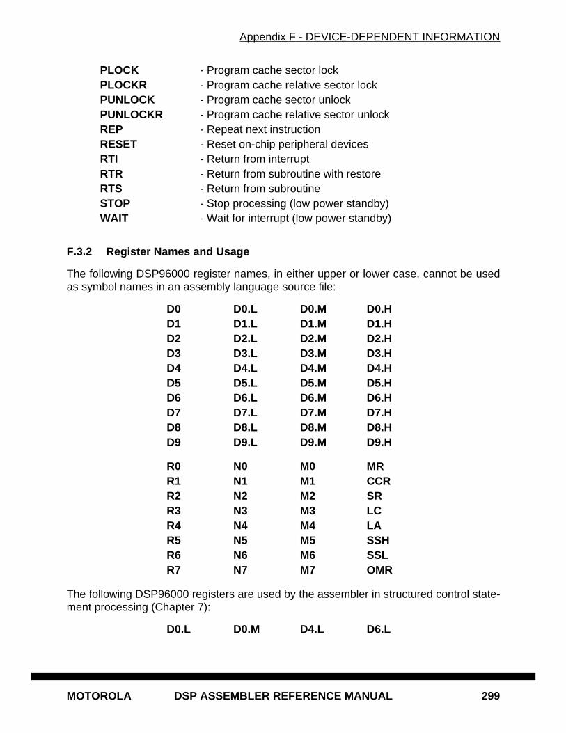
Appendix F - DEVICE-DEPENDENT INFORMATION
MOTOROLA DSP ASSEMBLER REFERENCE MANUAL 299
PLOCK - Program cache sector lockPLOCKR - Program cache relative sector lockPUNLOCK - Program cache sector unlockPUNLOCKR - Program cache relative sector unlockREP - Repeat next instructionRESET - Reset on-chip peripheral devicesRTI - Return from interruptRTR - Return from subroutine with restoreRTS - Return from subroutineSTOP - Stop processing (low power standby)WAIT - Wait for interrupt (low power standby)
F.3.2 Register Names and Usage
The following DSP96000 register names, in either upper or lower case, cannot be usedas symbol names in an assembly language source file:
D0 D0.L D0.M D0.HD1 D1.L D1.M D1.HD2 D2.L D2.M D2.HD3 D3.L D3.M D3.HD4 D4.L D4.M D4.HD5 D5.L D5.M D5.HD6 D6.L D6.M D6.HD7 D7.L D7.M D7.HD8 D8.L D8.M D8.HD9 D9.L D9.M D9.H
R0 N0 M0 MRR1 N1 M1 CCRR2 N2 M2 SRR3 N3 M3 LCR4 N4 M4 LAR5 N5 M5 SSHR6 N6 M6 SSLR7 N7 M7 OMR
The following DSP96000 registers are used by the assembler in structured control state-ment processing (Chapter 7):
D0.L D0.M D4.L D6.L
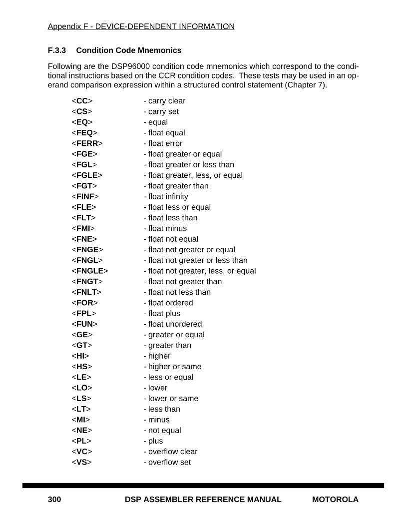
Appendix F - DEVICE-DEPENDENT INFORMATION
300 DSP ASSEMBLER REFERENCE MANUAL MOTOROLA
F.3.3 Condition Code Mnemonics
Following are the DSP96000 condition code mnemonics which correspond to the condi-tional instructions based on the CCR condition codes. These tests may be used in an op-erand comparison expression within a structured control statement (Chapter 7).
<CC> - carry clear<CS> - carry set<EQ> - equal<FEQ> - float equal<FERR> - float error<FGE> - float greater or equal<FGL> - float greater or less than<FGLE> - float greater, less, or equal<FGT> - float greater than<FINF> - float infinity<FLE> - float less or equal<FLT> - float less than<FMI> - float minus<FNE> - float not equal<FNGE> - float not greater or equal<FNGL> - float not greater or less than<FNGLE> - float not greater, less, or equal<FNGT> - float not greater than<FNLT> - float not less than<FOR> - float ordered<FPL> - float plus<FUN> - float unordered<GE> - greater or equal<GT> - greater than<HI> - higher<HS> - higher or same<LE> - less or equal<LO> - lower<LS> - lower or same<LT> - less than<MI> - minus<NE> - not equal<PL> - plus<VC> - overflow clear<VS> - overflow set
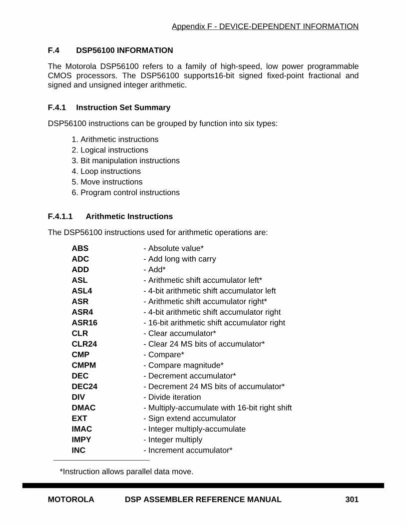
Appendix F - DEVICE-DEPENDENT INFORMATION
MOTOROLA DSP ASSEMBLER REFERENCE MANUAL 301
F.4 DSP56100 INFORMATION
The Motorola DSP56100 refers to a family of high-speed, low power programmableCMOS processors. The DSP56100 supports16-bit signed fixed-point fractional andsigned and unsigned integer arithmetic.
F.4.1 Instruction Set Summary
DSP56100 instructions can be grouped by function into six types:
1. Arithmetic instructions2. Logical instructions3. Bit manipulation instructions4. Loop instructions5. Move instructions6. Program control instructions
F.4.1.1 Arithmetic Instructions
The DSP56100 instructions used for arithmetic operations are:
ABS - Absolute value*ADC - Add long with carryADD - Add*ASL - Arithmetic shift accumulator left*ASL4 - 4-bit arithmetic shift accumulator leftASR - Arithmetic shift accumulator right*ASR4 - 4-bit arithmetic shift accumulator rightASR16 - 16-bit arithmetic shift accumulator rightCLR - Clear accumulator*CLR24 - Clear 24 MS bits of accumulator*CMP - Compare*CMPM - Compare magnitude*DEC - Decrement accumulator*DEC24 - Decrement 24 MS bits of accumulator*DIV - Divide iterationDMAC - Multiply-accumulate with 16-bit right shiftEXT - Sign extend accumulatorIMAC - Integer multiply-accumulateIMPY - Integer multiplyINC - Increment accumulator*
*Instruction allows parallel data move.

Appendix F - DEVICE-DEPENDENT INFORMATION
302 DSP ASSEMBLER REFERENCE MANUAL MOTOROLA
INC24 - Increment 24 MS bits of accumulator*MAC - Signed multiply-accumulate*MACR - Signed multiply-accumulate and round*MACSU - Signed/unsigned multiply-accumulateMACUU - Unsigned multiply-accumulateMPY - Signed multiply*MPYR - Signed multiply and round*MPYSU - Signed/unsigned multiplyMPYUU - Unsigned multiplyNEG - Negate accumulatorNEGC - Negate accumulator with carry*NORM - Normalize accumulator iterationRND - Round accumulator*SBC - Subtract long with carry*SUB - Subtract*SUBL - Shift left then subtract*SWAP - Swap accumulator wordsTcc - Transfer conditionallyTFR - Transfer data ALU register*TFR2 - Transfer data ALU registerTFR3 - Transfer data ALU registerTST - Test accumulator*TST2 - Test data ALU register*ZERO - Zero extend accumulator
F.4.1.2 Logical Instructions
The DSP56100 instructions used for logical operations are:
AND - Logical AND*ANDI - AND Immediate with control registerEOR - Logical exclusive OR*LSL - Logical shift accumulator left*LSR - Logical shift accumulator right*NOT - Logical complement on accumulator*OR - Logical inclusive OR*ORI - OR immediate with control registerROL - Rotate accumulator left*ROL - Rotate accumulator right*
*Instruction allows parallel data move.
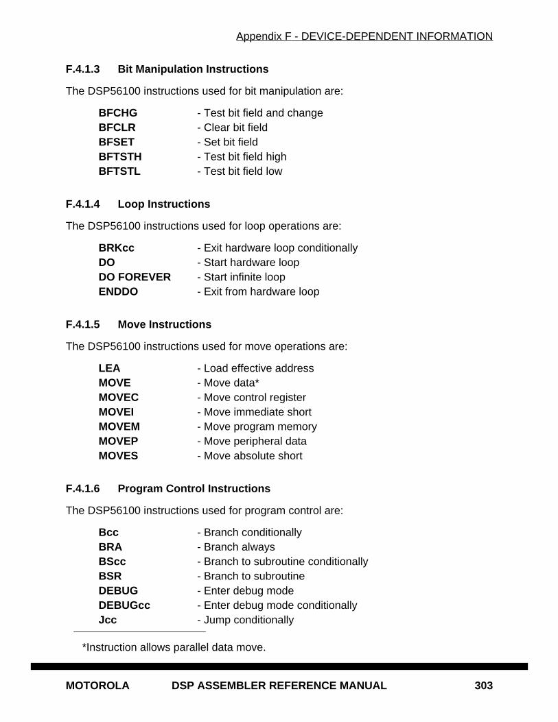
Appendix F - DEVICE-DEPENDENT INFORMATION
MOTOROLA DSP ASSEMBLER REFERENCE MANUAL 303
F.4.1.3 Bit Manipulation Instructions
The DSP56100 instructions used for bit manipulation are:
BFCHG - Test bit field and changeBFCLR - Clear bit fieldBFSET - Set bit fieldBFTSTH - Test bit field highBFTSTL - Test bit field low
F.4.1.4 Loop Instructions
The DSP56100 instructions used for loop operations are:
BRKcc - Exit hardware loop conditionallyDO - Start hardware loopDO FOREVER - Start infinite loopENDDO - Exit from hardware loop
F.4.1.5 Move Instructions
The DSP56100 instructions used for move operations are:
LEA - Load effective addressMOVE - Move data*MOVEC - Move control registerMOVEI - Move immediate shortMOVEM - Move program memoryMOVEP - Move peripheral dataMOVES - Move absolute short
F.4.1.6 Program Control Instructions
The DSP56100 instructions used for program control are:
Bcc - Branch conditionallyBRA - Branch alwaysBScc - Branch to subroutine conditionallyBSR - Branch to subroutineDEBUG - Enter debug modeDEBUGcc - Enter debug mode conditionallyJcc - Jump conditionally
*Instruction allows parallel data move.
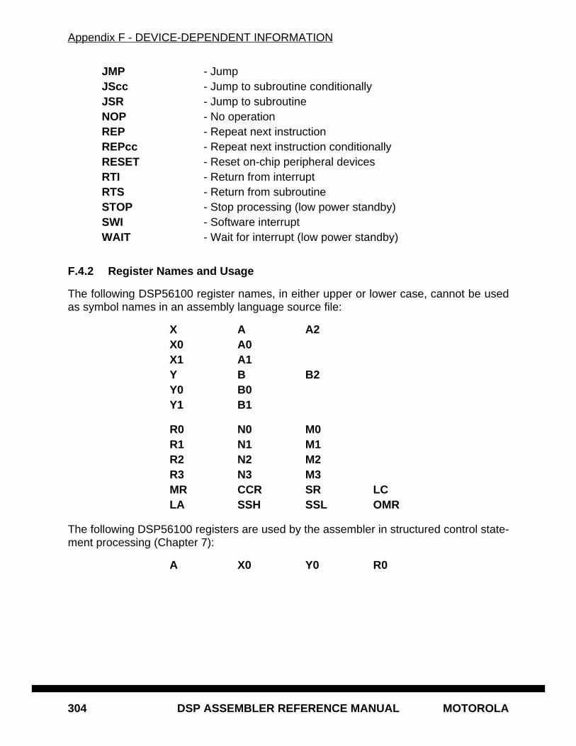
Appendix F - DEVICE-DEPENDENT INFORMATION
304 DSP ASSEMBLER REFERENCE MANUAL MOTOROLA
JMP - JumpJScc - Jump to subroutine conditionallyJSR - Jump to subroutineNOP - No operationREP - Repeat next instructionREPcc - Repeat next instruction conditionallyRESET - Reset on-chip peripheral devicesRTI - Return from interruptRTS - Return from subroutineSTOP - Stop processing (low power standby)SWI - Software interruptWAIT - Wait for interrupt (low power standby)
F.4.2 Register Names and Usage
The following DSP56100 register names, in either upper or lower case, cannot be usedas symbol names in an assembly language source file:
X A A2X0 A0X1 A1Y B B2Y0 B0Y1 B1
R0 N0 M0R1 N1 M1R2 N2 M2R3 N3 M3MR CCR SR LCLA SSH SSL OMR
The following DSP56100 registers are used by the assembler in structured control state-ment processing (Chapter 7):
A X0 Y0 R0
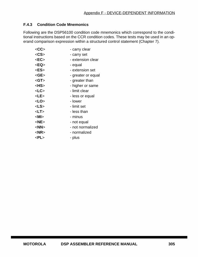
Appendix F - DEVICE-DEPENDENT INFORMATION
MOTOROLA DSP ASSEMBLER REFERENCE MANUAL 305
F.4.3 Condition Code Mnemonics
Following are the DSP56100 condition code mnemonics which correspond to the condi-tional instructions based on the CCR condition codes. These tests may be used in an op-erand comparison expression within a structured control statement (Chapter 7).
<CC> - carry clear<CS> - carry set<EC> - extension clear<EQ> - equal<ES> - extension set<GE> - greater or equal<GT> - greater than<HS> - higher or same<LC> - limit clear<LE> - less or equal<LO> - lower<LS> - limit set<LT> - less than<MI> - minus<NE> - not equal<NN> - not normalized<NR> - normalized<PL> - plus
Appendix F - DEVICE-DEPENDENT INFORMATION
306 DSP ASSEMBLER REFERENCE MANUAL MOTOROLA
MOTOROLA DSP ASSEMBLER REFERENCE MANUAL 307
Appendix GHOST-DEPENDENT INFORMATION
G.1 INTRODUCTION
The Motorola DSP development software runs on several host machine and operatingsystem platforms. The following sections give information on hardware requirements, in-stallation, and other topics relating to specific host environments. The descriptions belowrefer directly to the DSP assembler, but the sections on hardware requirements and in-stallation apply similarly to the DSP linker and librarian as well. See the appropriate chap-ters in the DSP Linker/Librarian Reference Manual for more information on invocationoptions and processing of these utilities.
G.2 DOS/386 ENVIRONMENT
The Motorola DSP assembler is delivered as an executable file on a high density 3 1/2"diskette. It may be run from either a floppy drive or a hard disk, although a hard disk isrecommended. The assembler will make use of extended memory if it is present, and willutilize available disk space if physical memory is exhausted.
G.2.1 Hardware Requirements
The minimum hardware requirements for the assembler in the DOS/386 environment in-clude:
386-based PC or compatible with 80386 (or higher) CPU, 4MB of RAM, and one3 1/2" HD diskette drive.
MS-DOS v3.0 or later.
Since the assembler uses all of available memory for storage of symbols and macros, theoptimal system configuration would have at least 4 megabytes of extended memory. Theassembler will make use of extended memory beyond 640K and may even use a virtualmemory disk file if necessary. A utility called PMINFO is supplied to provide memory re-gion tuning and virtual file sizing for systems running under Microsoft Windows or otherDOS extended memory managers.
Appendix G - HOST-DEPENDENT INFORMATION
308 DSP ASSEMBLER REFERENCE MANUAL MOTOROLA
G.2.2 Installation
Make a backup copy of the installation diskette using the DOS DISKCOPY command. Forexample, if the installation diskette is in drive A and a blank disk is in drive B, issue thefollowing command:
DISKCOPY A: B:
Put the distribution diskette in a safe place as a backup.
If the INSTALL.EXE program is present on the distribution disk it can be used to installthe assembler software. Insert the diskette into drive A and enter the following command:
A:INSTALL
The install program will then query for information about the host system and where thesoftware should be placed.
If there is no installation program, create a directory where the assembler can reside andcopy the executable file into it. For example, if a directory has been created called BINwhich holds all executable files on the hard disk, and the hard disk is the current loggeddisk, the following command will copy the assembler from the installation diskette in driveA to that directory:
COPY A:ASM56000.EXE \BIN
Again, keep the assembler distribution diskette in a safe place as a backup.
G.2.3 Source File Text
Input to the assembler should be in a standard ASCII text file with carriage return/line feedcharacter pairs as line terminators. This type of file is created by most standard text editingprograms used on 386 PCs, such as the DOS-supplied editor EDIT.
Using word processing packages for creating assembler input source files is a little moreinvolved, but can certainly be done. Word processing packages use special character en-codings to indicate format and font settings, margins, indentation, and so forth. In somecases these special encodings violate the input requirements of the assembler, and mustbe removed or changed.
Most word processing programs have a facility for converting internal-format documentsto standard ASCII text files. See Chapter 2, INPUT FILE FORMAT, for more informationon the form and content of assembler input files.
G.2.4 Invoking the Assembler
The assembler is invoked from the DOS command line by entering the name of the as-sembler executable without the extension, followed by any desired options, and finally the
Appendix G - HOST-DEPENDENT INFORMATION
MOTOROLA DSP ASSEMBLER REFERENCE MANUAL 309
names of the source files to be assembled. See Chapter 1, RUNNING THE ASSEM-BLER, for a list of options which can be included on the command line.
As an example, if the assembler diskette was loaded in drive A, and the source file waslocated on the disk in drive B, the following command at the DOS prompt would assemblethe file MYFILE.ASM , putting the object file MYFILE.CLN and the listing file OUT-FILE.LST onto the disk in drive B as output:
A:ASM56000 -B b:myfile.cln -Lb:outfile.lst b:myfile
Since DOS supports standard input and output channels, in the example above any warn-ing or error messages would appear both in the listing file and on the standard output (bydefault the console screen).
DOS also supports I/O redirection, so that the assembler listing can be sent to a file ordirectly to an output device. Given a hard disk environment where the assembler execut-able has been loaded into a directory BIN that is in the program search path, the followingcommand will assemble the source file FFT.ASM and send the listing output directly tothe Line Printer 1 device:
ASM56000 fft.dsp >LPT1:
In this example no object file is created and all errors and warnings are sent to LPT1: (e.g.they do not appear on the console screen). The input file is assumed to be in the currentdirectory. See the IBM or Microsoft DOS manual for more information on directory struc-ture, I/O redirection, and command paths.
G.3 SunOS ENVIRONMENT
The Motorola DSP assembler is delivered on a 3 1/2" diskette written in SunOS bar for-mat.
G.3.1 Hardware Requirements
The assembler will run on any Sparc workstation running SunOS version 4.0 or later.
G.3.2 Installation
The assembler and any accompanying support files may be read from diskette into thecurrent directory using the following bar command sequence:
bar xvZf /dev/rfd0
The assembler may be placed in any generally accessible area, usually /usr/bin or /usr/local/bin . Be sure that it is located in a directory listing in the PATH environment variableof those who need to use it. Also, insure that the execute access bits for the file are setwhen it is copied to disk; this can be done with the chmod utility (see your User Manualfor information on chmod ).
Appendix G - HOST-DEPENDENT INFORMATION
310 DSP ASSEMBLER REFERENCE MANUAL MOTOROLA
G.3.3 Source File Text
Input to the assembler should be a standard ASCII text file with newline characters (ASCIILF, 0AH) as line terminators. This type of file is created by the standard Unix text editorssuch as vi , and by other editors which run in the SunOS environment such as Emacs.
Assembler source code imported from other environments may need to be converted, de-pending on the level of filtering done on the code when it was transferred to the Sun sys-tem. Binary text files sent from, for example, a PC or compatible machine will need to havecarriage return characters (ASCII CR, 0DH) and possibly end-of-file markers (ASCII SUB,1AH) stripped before being processed by the assembler.
G.3.4 Invoking the Assembler
The assembler is invoked from the shell (usually csh in SunOS) by entering the name ofthe assembler executable, followed by any desired options, and finally the names of thesource files to be assembled. See Chapter 1, RUNNING THE ASSEMBLER, for a list ofoptions which can be included on the command line.
As an example, if the assembler executable was located in a directory listed in the userPATH environment variable, the following command would assemble the file myfile.asmin the current working directory, putting the object file myfile in the objects subdirectoryand the listing file outfile into the listings subdirectory:
asm96000 -bobjects/myfile.cln -llistings/outfile.lst myfile
Since SunOS supports standard input and output channels, in the example above anywarning or error messages would appear both in the listing file and on the standard output(by default the terminal screen).
SunOS also supports I/O redirection, so that the assembler listing can be sent to a file orarbitrary output device. Assume a user wanted a list of errors from the assembly, but a fullsource code listing was not required. This can be accomplished with the following assem-bler command line:
asm96000 -l/dev/null test >test.err
In this example no object file is created and all errors and warnings are routed to the filetest.err . The input file test.asm is assumed to be in the current working directory. Notethat the -L option is used to send the full assembler listing to the null device.
G.4 MACINTOSH ENVIRONMENT
The Motorola DSP assembler is delivered as an MPW executable tool on a double-sided3 1/2" Macintosh diskette. It may be run from either a floppy drive or a hard disk. The as-sembler currently makes no use of disk for work space, and requires adequate secondarystorage only for the output object file and the listing file, if the latter is routed to disk.
Appendix G - HOST-DEPENDENT INFORMATION
MOTOROLA DSP ASSEMBLER REFERENCE MANUAL 311
G.4.1 Hardware Requirements
The minimum hardware requirements for the assembler in the Macintosh environment in-clude:
Macintosh with 68020 (or later) CPU, 4MB of RAM, and one 3 1/2" diskette drive.System/Finder v6.0 or laterMacintosh Programmer’s Workshop (MPW) v2.0 or later.
Since the assembler uses all of available memory for storage of symbols and macros, theoptimal system configuration would have at least 4megabytes of memory.
G.4.2 Installation
Make a working copy of the assembler by formatting a new diskette and copying the as-sembler executable file onto it. For example, on a Macintosh II with only one diskette drive(no hard disk), insert the destination diskette then immediately eject it using the Ejectmenu selection in the Files menu; this will leave a shadow icon of the destination disk.Insert the source diskette, open it, then drag the assembler executable into the shadowicon of the destination diskette. The machine will begin reading from the source diskette,and will display a dialogue box when it is ready to write the destination diskette. Put theassembler distribution diskette in a safe place as a backup.
For hard disks, create a folder where the assembler can reside and copy the executablefile into it. Alternatively, copy the assembler executable into the MPW tools folder so thatit is readily accessible by the MPW shell. Again, keep the assembler distribution diskettein a safe place as a backup.
G.4.3 Source File Text
Input to the assembler should be in a standard ASCII text file with carriage return charac-ters (ASCII CR, 0DH) as line terminators. This type of file is created by most standard textediting programs used on the Macintosh, such as TeachText or the Macintosh Program-mer’s Workshop editor.
Using word processing packages for creating assembler input source files is a little moreinvolved, but can certainly be done. Word processing packages use special character en-codings to indicate format and font settings, margins, indentation, and so forth. In somecases these special encodings violate the input requirements of the assembler, and mustbe removed or changed.
Microsoft Word allows the programmer to save a file as plain ASCII text. Select SaveAs... from the Files pull-down menu, then click the File Format... button. The programwill display a list of format options. Select Text Only , click OK, then save as usual.
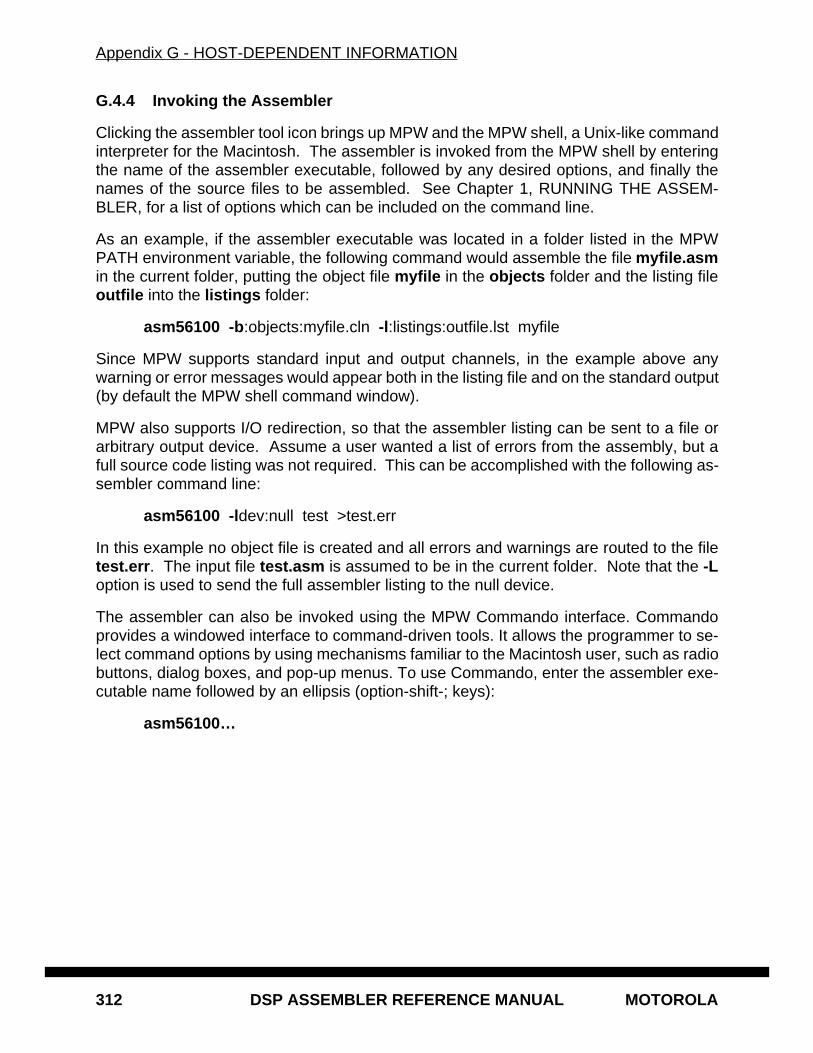
Appendix G - HOST-DEPENDENT INFORMATION
312 DSP ASSEMBLER REFERENCE MANUAL MOTOROLA
G.4.4 Invoking the Assembler
Clicking the assembler tool icon brings up MPW and the MPW shell, a Unix-like commandinterpreter for the Macintosh. The assembler is invoked from the MPW shell by enteringthe name of the assembler executable, followed by any desired options, and finally thenames of the source files to be assembled. See Chapter 1, RUNNING THE ASSEM-BLER, for a list of options which can be included on the command line.
As an example, if the assembler executable was located in a folder listed in the MPWPATH environment variable, the following command would assemble the file myfile.asmin the current folder, putting the object file myfile in the objects folder and the listing fileoutfile into the listings folder:
asm56100 -b:objects:myfile.cln -l:listings:outfile.lst myfile
Since MPW supports standard input and output channels, in the example above anywarning or error messages would appear both in the listing file and on the standard output(by default the MPW shell command window).
MPW also supports I/O redirection, so that the assembler listing can be sent to a file orarbitrary output device. Assume a user wanted a list of errors from the assembly, but afull source code listing was not required. This can be accomplished with the following as-sembler command line:
asm56100 -ldev:null test >test.err
In this example no object file is created and all errors and warnings are routed to the filetest.err . The input file test.asm is assumed to be in the current folder. Note that the -Loption is used to send the full assembler listing to the null device.
The assembler can also be invoked using the MPW Commando interface. Commandoprovides a windowed interface to command-driven tools. It allows the programmer to se-lect command options by using mechanisms familiar to the Macintosh user, such as radiobuttons, dialog boxes, and pop-up menus. To use Commando, enter the assembler exe-cutable name followed by an ellipsis (option-shift-; keys):
asm56100…
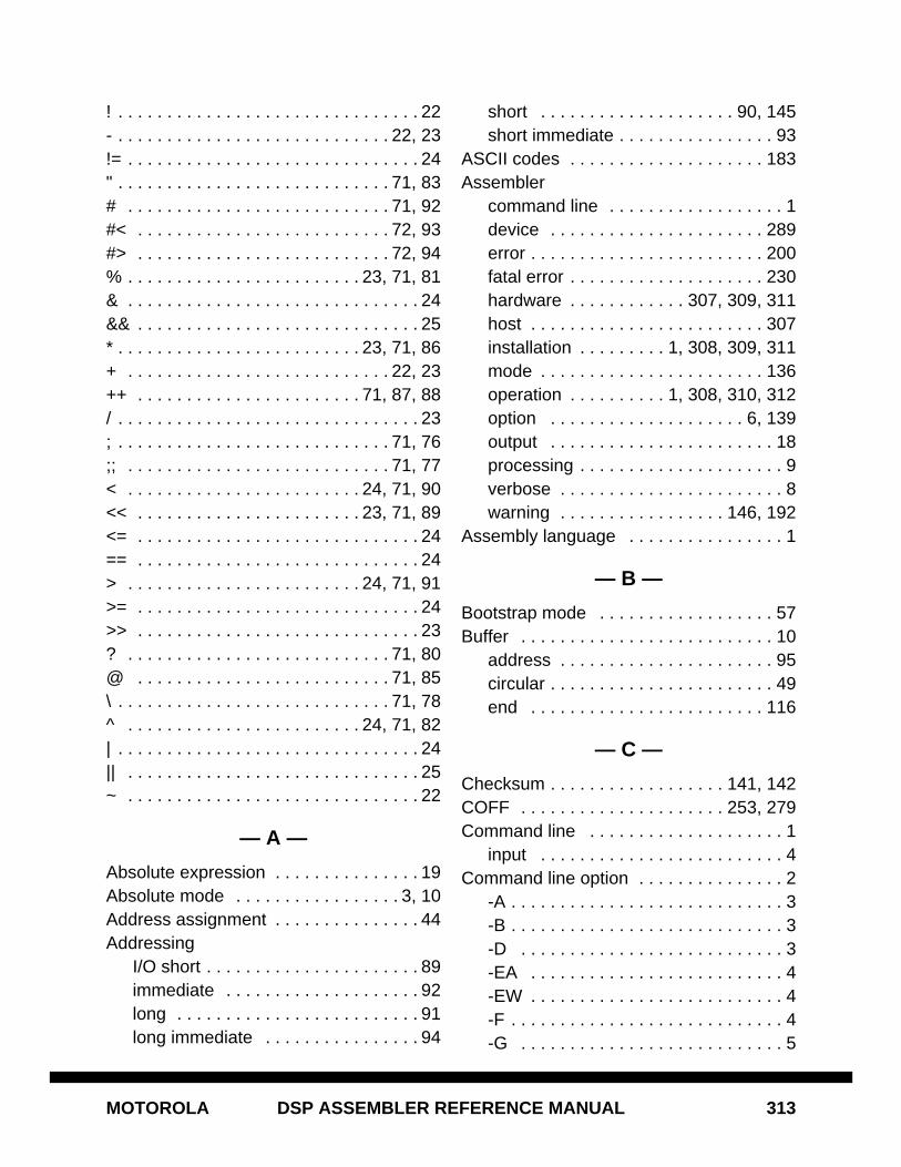
MOTOROLA DSP ASSEMBLER REFERENCE MANUAL 313
! . . . . . . . . . . . . . . . . . . . . . . . . . . . . . . . 22- . . . . . . . . . . . . . . . . . . . . . . . . . . . . 22, 23!= . . . . . . . . . . . . . . . . . . . . . . . . . . . . . . 24" . . . . . . . . . . . . . . . . . . . . . . . . . . . . 71, 83# . . . . . . . . . . . . . . . . . . . . . . . . . . . 71, 92#< . . . . . . . . . . . . . . . . . . . . . . . . . . 72, 93#> . . . . . . . . . . . . . . . . . . . . . . . . . . 72, 94% . . . . . . . . . . . . . . . . . . . . . . . . 23, 71, 81& . . . . . . . . . . . . . . . . . . . . . . . . . . . . . . 24&& . . . . . . . . . . . . . . . . . . . . . . . . . . . . . 25* . . . . . . . . . . . . . . . . . . . . . . . . . 23, 71, 86+ . . . . . . . . . . . . . . . . . . . . . . . . . . . 22, 23++ . . . . . . . . . . . . . . . . . . . . . . . 71, 87, 88/ . . . . . . . . . . . . . . . . . . . . . . . . . . . . . . . 23; . . . . . . . . . . . . . . . . . . . . . . . . . . . . 71, 76;; . . . . . . . . . . . . . . . . . . . . . . . . . . . 71, 77< . . . . . . . . . . . . . . . . . . . . . . . . 24, 71, 90<< . . . . . . . . . . . . . . . . . . . . . . . 23, 71, 89<= . . . . . . . . . . . . . . . . . . . . . . . . . . . . . 24== . . . . . . . . . . . . . . . . . . . . . . . . . . . . . 24> . . . . . . . . . . . . . . . . . . . . . . . . 24, 71, 91>= . . . . . . . . . . . . . . . . . . . . . . . . . . . . . 24>> . . . . . . . . . . . . . . . . . . . . . . . . . . . . . 23? . . . . . . . . . . . . . . . . . . . . . . . . . . . 71, 80@ . . . . . . . . . . . . . . . . . . . . . . . . . . 71, 85\ . . . . . . . . . . . . . . . . . . . . . . . . . . . . 71, 78^ . . . . . . . . . . . . . . . . . . . . . . . . 24, 71, 82| . . . . . . . . . . . . . . . . . . . . . . . . . . . . . . . 24|| . . . . . . . . . . . . . . . . . . . . . . . . . . . . . . 25~ . . . . . . . . . . . . . . . . . . . . . . . . . . . . . . 22
— A —
Absolute expression . . . . . . . . . . . . . . . 19Absolute mode . . . . . . . . . . . . . . . . . 3, 10Address assignment . . . . . . . . . . . . . . . 44Addressing
I/O short . . . . . . . . . . . . . . . . . . . . . . 89immediate . . . . . . . . . . . . . . . . . . . . 92long . . . . . . . . . . . . . . . . . . . . . . . . . 91long immediate . . . . . . . . . . . . . . . . 94
short . . . . . . . . . . . . . . . . . . . . 90, 145short immediate . . . . . . . . . . . . . . . . 93
ASCII codes . . . . . . . . . . . . . . . . . . . . 183Assembler
command line . . . . . . . . . . . . . . . . . . 1device . . . . . . . . . . . . . . . . . . . . . . 289error . . . . . . . . . . . . . . . . . . . . . . . . 200fatal error . . . . . . . . . . . . . . . . . . . . 230hardware . . . . . . . . . . . . 307, 309, 311host . . . . . . . . . . . . . . . . . . . . . . . . 307installation . . . . . . . . . 1, 308, 309, 311mode . . . . . . . . . . . . . . . . . . . . . . . 136operation . . . . . . . . . . 1, 308, 310, 312option . . . . . . . . . . . . . . . . . . . . 6, 139output . . . . . . . . . . . . . . . . . . . . . . . 18processing . . . . . . . . . . . . . . . . . . . . . 9verbose . . . . . . . . . . . . . . . . . . . . . . . 8warning . . . . . . . . . . . . . . . . . 146, 192
Assembly language . . . . . . . . . . . . . . . . 1
— B —
Bootstrap mode . . . . . . . . . . . . . . . . . . 57Buffer . . . . . . . . . . . . . . . . . . . . . . . . . . 10
address . . . . . . . . . . . . . . . . . . . . . . 95circular . . . . . . . . . . . . . . . . . . . . . . . 49end . . . . . . . . . . . . . . . . . . . . . . . . 116
— C —
Checksum . . . . . . . . . . . . . . . . . . 141, 142COFF . . . . . . . . . . . . . . . . . . . . . 253, 279Command line . . . . . . . . . . . . . . . . . . . . 1
input . . . . . . . . . . . . . . . . . . . . . . . . . 4Command line option . . . . . . . . . . . . . . . 2
-A . . . . . . . . . . . . . . . . . . . . . . . . . . . . 3-B . . . . . . . . . . . . . . . . . . . . . . . . . . . . 3-D . . . . . . . . . . . . . . . . . . . . . . . . . . . 3-EA . . . . . . . . . . . . . . . . . . . . . . . . . . 4-EW . . . . . . . . . . . . . . . . . . . . . . . . . . 4-F . . . . . . . . . . . . . . . . . . . . . . . . . . . . 4-G . . . . . . . . . . . . . . . . . . . . . . . . . . . 5
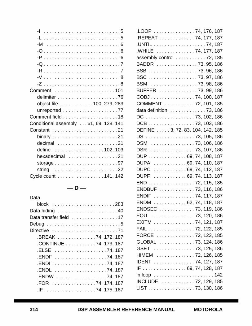
314 DSP ASSEMBLER REFERENCE MANUAL MOTOROLA
-I . . . . . . . . . . . . . . . . . . . . . . . . . . . . 5-L . . . . . . . . . . . . . . . . . . . . . . . . . . . . 5-M . . . . . . . . . . . . . . . . . . . . . . . . . . . 6-O . . . . . . . . . . . . . . . . . . . . . . . . . . . . 6-P . . . . . . . . . . . . . . . . . . . . . . . . . . . . 6-Q . . . . . . . . . . . . . . . . . . . . . . . . . . . . 7-R . . . . . . . . . . . . . . . . . . . . . . . . . . . . 7-V . . . . . . . . . . . . . . . . . . . . . . . . . . . . 8-Z . . . . . . . . . . . . . . . . . . . . . . . . . . . . 8
Comment . . . . . . . . . . . . . . . . . . . . . . 101delimiter . . . . . . . . . . . . . . . . . . . . . . 76object file . . . . . . . . . . . . 100, 279, 283unreported . . . . . . . . . . . . . . . . . . . . 77
Comment field . . . . . . . . . . . . . . . . . . . . 18Conditional assembly . . . 61, 69, 128, 141Constant . . . . . . . . . . . . . . . . . . . . . . . . 21
binary . . . . . . . . . . . . . . . . . . . . . . . . 21decimal . . . . . . . . . . . . . . . . . . . . . . 21define . . . . . . . . . . . . . . . . . . . 102, 103hexadecimal . . . . . . . . . . . . . . . . . . 21storage . . . . . . . . . . . . . . . . . . . . . . . 97string . . . . . . . . . . . . . . . . . . . . . . . . 22
Cycle count . . . . . . . . . . . . . . . . . 141, 142
— D —
Datablock . . . . . . . . . . . . . . . . . . . . . . . 283
Data hiding . . . . . . . . . . . . . . . . . . . . . . 40Data transfer field . . . . . . . . . . . . . . . . . 17Debug . . . . . . . . . . . . . . . . . . . . . . . . . . . 5Directive . . . . . . . . . . . . . . . . . . . . . . . . 71
.BREAK . . . . . . . . . . . . . . 74, 172, 187
.CONTINUE . . . . . . . . . . . 74, 173, 187
.ELSE . . . . . . . . . . . . . . . . . . . 74, 187
.ENDF . . . . . . . . . . . . . . . . . . . 74, 187
.ENDI . . . . . . . . . . . . . . . . . . . . 74, 187
.ENDL . . . . . . . . . . . . . . . . . . . 74, 187
.ENDW . . . . . . . . . . . . . . . . . . . 74, 187
.FOR . . . . . . . . . . . . . . . . 74, 174, 187
.IF . . . . . . . . . . . . . . . . . . 74, 175, 187
.LOOP . . . . . . . . . . . . . . . 74, 176, 187
.REPEAT . . . . . . . . . . . . . 74, 177, 187
.UNTIL . . . . . . . . . . . . . . . . . . . 74, 187
.WHILE . . . . . . . . . . . . . . 74, 177, 187assembly control . . . . . . . . . . . 72, 185BADDR . . . . . . . . . . . . . . . 73, 95, 186BSB . . . . . . . . . . . . . . . . . . 73, 96, 186BSC . . . . . . . . . . . . . . . . . . 73, 97, 186BSM . . . . . . . . . . . . . . . . . 73, 98, 186BUFFER . . . . . . . . . . . . . . 73, 99, 186COBJ . . . . . . . . . . . . . . . . 74, 100, 187COMMENT . . . . . . . . . . . 72, 101, 185data definition . . . . . . . . . . . . . 73, 186DC . . . . . . . . . . . . . . . . . . 73, 102, 186DCB . . . . . . . . . . . . . . . . . 73, 103, 186DEFINE . . . . . 3, 72, 83, 104, 142, 185DS . . . . . . . . . . . . . . . . . . 73, 105, 186DSM . . . . . . . . . . . . . . . . 73, 106, 186DSR . . . . . . . . . . . . . . . . . 73, 107, 186DUP . . . . . . . . . . . . . . 69, 74, 108, 187DUPA . . . . . . . . . . . . 69, 74, 110, 187DUPC . . . . . . . . . . . . 69, 74, 112, 187DUPF . . . . . . . . . . . . 69, 74, 113, 187END . . . . . . . . . . . . . . . . . 72, 115, 185ENDBUF . . . . . . . . . . . . . 73, 116, 186ENDIF . . . . . . . . . . . . . . . 74, 117, 187ENDM . . . . . . . . . . . . 62, 74, 118, 187ENDSEC . . . . . . . . . . . . . 73, 119, 186EQU . . . . . . . . . . . . . . . . 73, 120, 186EXITM . . . . . . . . . . . . . . . 74, 121, 187FAIL . . . . . . . . . . . . . . . . . 72, 122, 185FORCE . . . . . . . . . . . . . . 72, 123, 185GLOBAL . . . . . . . . . . . . . 73, 124, 186GSET . . . . . . . . . . . . . . . 73, 125, 186HIMEM . . . . . . . . . . . . . . 72, 126, 185IDENT . . . . . . . . . . . . . . . 74, 127, 187IF . . . . . . . . . . . . . . . . 69, 74, 128, 187in loop . . . . . . . . . . . . . . . . . . . . . . 142INCLUDE . . . . . . . . . . . . 72, 129, 185LIST . . . . . . . . . . . . . . . . . 73, 130, 186
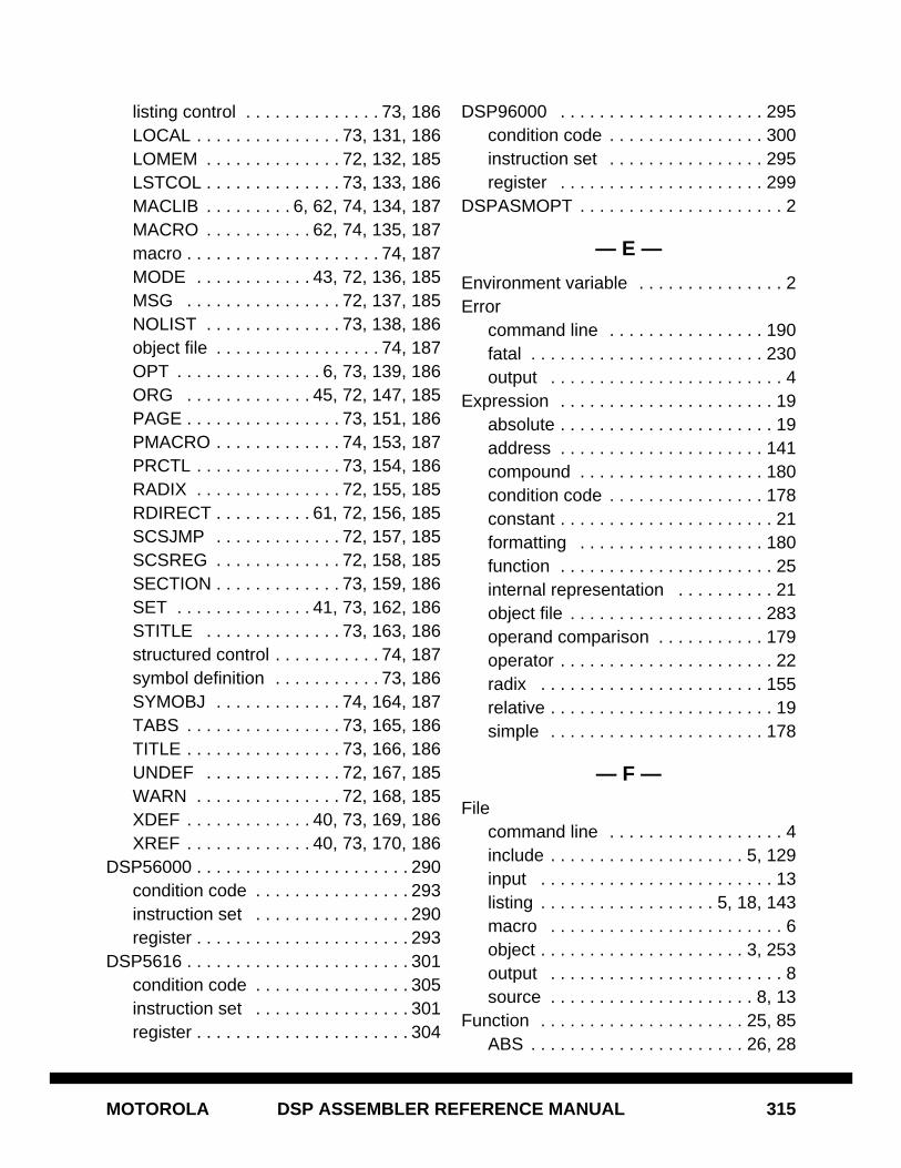
MOTOROLA DSP ASSEMBLER REFERENCE MANUAL 315
listing control . . . . . . . . . . . . . . 73, 186LOCAL . . . . . . . . . . . . . . . 73, 131, 186LOMEM . . . . . . . . . . . . . . 72, 132, 185LSTCOL . . . . . . . . . . . . . . 73, 133, 186MACLIB . . . . . . . . . 6, 62, 74, 134, 187MACRO . . . . . . . . . . . 62, 74, 135, 187macro . . . . . . . . . . . . . . . . . . . . 74, 187MODE . . . . . . . . . . . . 43, 72, 136, 185MSG . . . . . . . . . . . . . . . . 72, 137, 185NOLIST . . . . . . . . . . . . . . 73, 138, 186object file . . . . . . . . . . . . . . . . . 74, 187OPT . . . . . . . . . . . . . . . 6, 73, 139, 186ORG . . . . . . . . . . . . . 45, 72, 147, 185PAGE . . . . . . . . . . . . . . . . 73, 151, 186PMACRO . . . . . . . . . . . . . 74, 153, 187PRCTL . . . . . . . . . . . . . . . 73, 154, 186RADIX . . . . . . . . . . . . . . . 72, 155, 185RDIRECT . . . . . . . . . . 61, 72, 156, 185SCSJMP . . . . . . . . . . . . . 72, 157, 185SCSREG . . . . . . . . . . . . . 72, 158, 185SECTION . . . . . . . . . . . . . 73, 159, 186SET . . . . . . . . . . . . . . 41, 73, 162, 186STITLE . . . . . . . . . . . . . . 73, 163, 186structured control . . . . . . . . . . . 74, 187symbol definition . . . . . . . . . . . 73, 186SYMOBJ . . . . . . . . . . . . . 74, 164, 187TABS . . . . . . . . . . . . . . . . 73, 165, 186TITLE . . . . . . . . . . . . . . . . 73, 166, 186UNDEF . . . . . . . . . . . . . . 72, 167, 185WARN . . . . . . . . . . . . . . . 72, 168, 185XDEF . . . . . . . . . . . . . 40, 73, 169, 186XREF . . . . . . . . . . . . . 40, 73, 170, 186
DSP56000 . . . . . . . . . . . . . . . . . . . . . . 290condition code . . . . . . . . . . . . . . . . 293instruction set . . . . . . . . . . . . . . . . 290register . . . . . . . . . . . . . . . . . . . . . . 293
DSP5616 . . . . . . . . . . . . . . . . . . . . . . . 301condition code . . . . . . . . . . . . . . . . 305instruction set . . . . . . . . . . . . . . . . 301register . . . . . . . . . . . . . . . . . . . . . . 304
DSP96000 . . . . . . . . . . . . . . . . . . . . . 295condition code . . . . . . . . . . . . . . . . 300instruction set . . . . . . . . . . . . . . . . 295register . . . . . . . . . . . . . . . . . . . . . 299
DSPASMOPT . . . . . . . . . . . . . . . . . . . . . 2
— E —
Environment variable . . . . . . . . . . . . . . . 2Error
command line . . . . . . . . . . . . . . . . 190fatal . . . . . . . . . . . . . . . . . . . . . . . . 230output . . . . . . . . . . . . . . . . . . . . . . . . 4
Expression . . . . . . . . . . . . . . . . . . . . . . 19absolute . . . . . . . . . . . . . . . . . . . . . . 19address . . . . . . . . . . . . . . . . . . . . . 141compound . . . . . . . . . . . . . . . . . . . 180condition code . . . . . . . . . . . . . . . . 178constant . . . . . . . . . . . . . . . . . . . . . . 21formatting . . . . . . . . . . . . . . . . . . . 180function . . . . . . . . . . . . . . . . . . . . . . 25internal representation . . . . . . . . . . 21object file . . . . . . . . . . . . . . . . . . . . 283operand comparison . . . . . . . . . . . 179operator . . . . . . . . . . . . . . . . . . . . . . 22radix . . . . . . . . . . . . . . . . . . . . . . . 155relative . . . . . . . . . . . . . . . . . . . . . . . 19simple . . . . . . . . . . . . . . . . . . . . . . 178
— F —
Filecommand line . . . . . . . . . . . . . . . . . . 4include . . . . . . . . . . . . . . . . . . . . 5, 129input . . . . . . . . . . . . . . . . . . . . . . . . 13listing . . . . . . . . . . . . . . . . . . 5, 18, 143macro . . . . . . . . . . . . . . . . . . . . . . . . 6object . . . . . . . . . . . . . . . . . . . . . 3, 253output . . . . . . . . . . . . . . . . . . . . . . . . 8source . . . . . . . . . . . . . . . . . . . . . 8, 13
Function . . . . . . . . . . . . . . . . . . . . . 25, 85ABS . . . . . . . . . . . . . . . . . . . . . . 26, 28
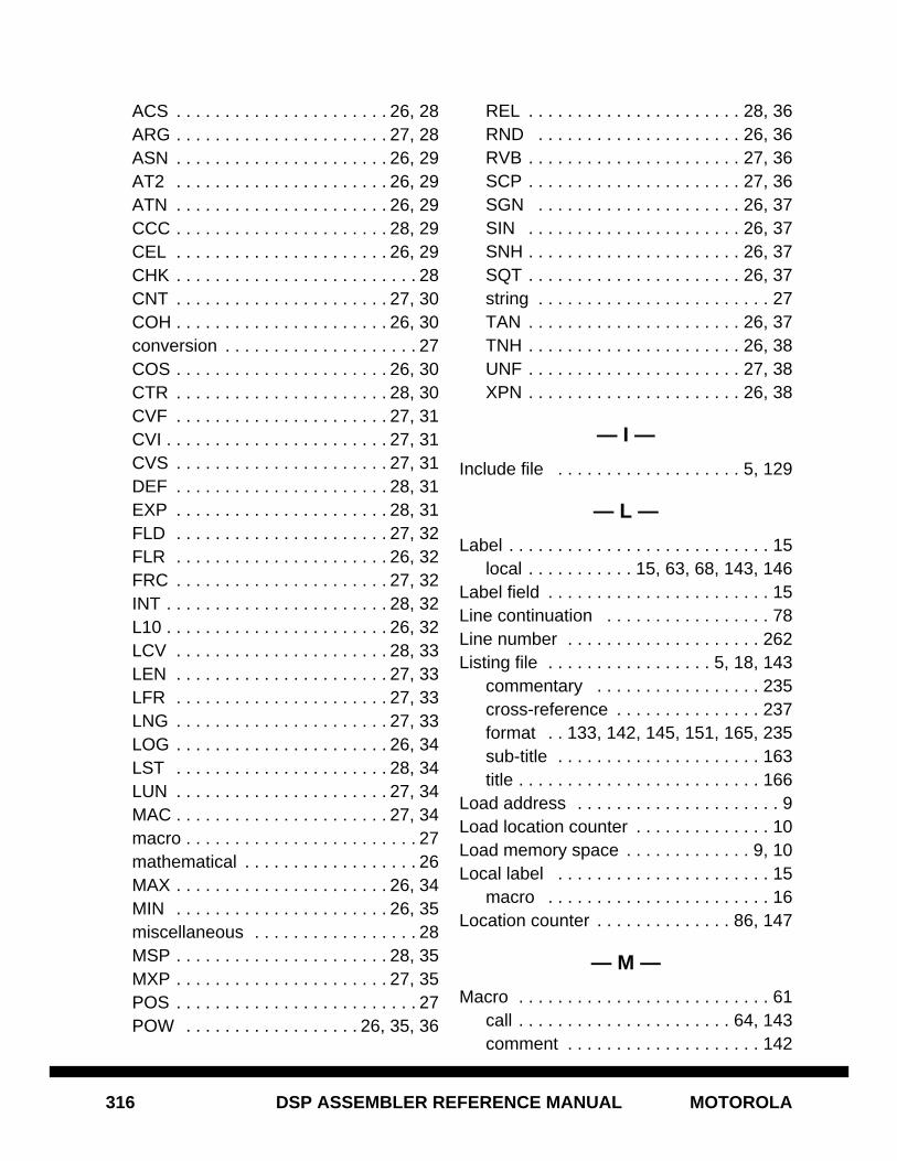
316 DSP ASSEMBLER REFERENCE MANUAL MOTOROLA
ACS . . . . . . . . . . . . . . . . . . . . . . 26, 28ARG . . . . . . . . . . . . . . . . . . . . . . 27, 28ASN . . . . . . . . . . . . . . . . . . . . . . 26, 29AT2 . . . . . . . . . . . . . . . . . . . . . . 26, 29ATN . . . . . . . . . . . . . . . . . . . . . . 26, 29CCC . . . . . . . . . . . . . . . . . . . . . . 28, 29CEL . . . . . . . . . . . . . . . . . . . . . . 26, 29CHK . . . . . . . . . . . . . . . . . . . . . . . . . 28CNT . . . . . . . . . . . . . . . . . . . . . . 27, 30COH . . . . . . . . . . . . . . . . . . . . . . 26, 30conversion . . . . . . . . . . . . . . . . . . . . 27COS . . . . . . . . . . . . . . . . . . . . . . 26, 30CTR . . . . . . . . . . . . . . . . . . . . . . 28, 30CVF . . . . . . . . . . . . . . . . . . . . . . 27, 31CVI . . . . . . . . . . . . . . . . . . . . . . . 27, 31CVS . . . . . . . . . . . . . . . . . . . . . . 27, 31DEF . . . . . . . . . . . . . . . . . . . . . . 28, 31EXP . . . . . . . . . . . . . . . . . . . . . . 28, 31FLD . . . . . . . . . . . . . . . . . . . . . . 27, 32FLR . . . . . . . . . . . . . . . . . . . . . . 26, 32FRC . . . . . . . . . . . . . . . . . . . . . . 27, 32INT . . . . . . . . . . . . . . . . . . . . . . . 28, 32L10 . . . . . . . . . . . . . . . . . . . . . . . 26, 32LCV . . . . . . . . . . . . . . . . . . . . . . 28, 33LEN . . . . . . . . . . . . . . . . . . . . . . 27, 33LFR . . . . . . . . . . . . . . . . . . . . . . 27, 33LNG . . . . . . . . . . . . . . . . . . . . . . 27, 33LOG . . . . . . . . . . . . . . . . . . . . . . 26, 34LST . . . . . . . . . . . . . . . . . . . . . . 28, 34LUN . . . . . . . . . . . . . . . . . . . . . . 27, 34MAC . . . . . . . . . . . . . . . . . . . . . . 27, 34macro . . . . . . . . . . . . . . . . . . . . . . . . 27mathematical . . . . . . . . . . . . . . . . . . 26MAX . . . . . . . . . . . . . . . . . . . . . . 26, 34MIN . . . . . . . . . . . . . . . . . . . . . . 26, 35miscellaneous . . . . . . . . . . . . . . . . . 28MSP . . . . . . . . . . . . . . . . . . . . . . 28, 35MXP . . . . . . . . . . . . . . . . . . . . . . 27, 35POS . . . . . . . . . . . . . . . . . . . . . . . . . 27POW . . . . . . . . . . . . . . . . . . 26, 35, 36
REL . . . . . . . . . . . . . . . . . . . . . . 28, 36RND . . . . . . . . . . . . . . . . . . . . . 26, 36RVB . . . . . . . . . . . . . . . . . . . . . . 27, 36SCP . . . . . . . . . . . . . . . . . . . . . . 27, 36SGN . . . . . . . . . . . . . . . . . . . . . 26, 37SIN . . . . . . . . . . . . . . . . . . . . . . 26, 37SNH . . . . . . . . . . . . . . . . . . . . . . 26, 37SQT . . . . . . . . . . . . . . . . . . . . . . 26, 37string . . . . . . . . . . . . . . . . . . . . . . . . 27TAN . . . . . . . . . . . . . . . . . . . . . . 26, 37TNH . . . . . . . . . . . . . . . . . . . . . . 26, 38UNF . . . . . . . . . . . . . . . . . . . . . . 27, 38XPN . . . . . . . . . . . . . . . . . . . . . . 26, 38
— I —
Include file . . . . . . . . . . . . . . . . . . . 5, 129
— L —
Label . . . . . . . . . . . . . . . . . . . . . . . . . . . 15local . . . . . . . . . . . 15, 63, 68, 143, 146
Label field . . . . . . . . . . . . . . . . . . . . . . . 15Line continuation . . . . . . . . . . . . . . . . . 78Line number . . . . . . . . . . . . . . . . . . . . 262Listing file . . . . . . . . . . . . . . . . . 5, 18, 143
commentary . . . . . . . . . . . . . . . . . 235cross-reference . . . . . . . . . . . . . . . 237format . . 133, 142, 145, 151, 165, 235sub-title . . . . . . . . . . . . . . . . . . . . . 163title . . . . . . . . . . . . . . . . . . . . . . . . . 166
Load address . . . . . . . . . . . . . . . . . . . . . 9Load location counter . . . . . . . . . . . . . . 10Load memory space . . . . . . . . . . . . . 9, 10Local label . . . . . . . . . . . . . . . . . . . . . . 15
macro . . . . . . . . . . . . . . . . . . . . . . . 16Location counter . . . . . . . . . . . . . . 86, 147
— M —
Macro . . . . . . . . . . . . . . . . . . . . . . . . . . 61call . . . . . . . . . . . . . . . . . . . . . . 64, 143comment . . . . . . . . . . . . . . . . . . . . 142
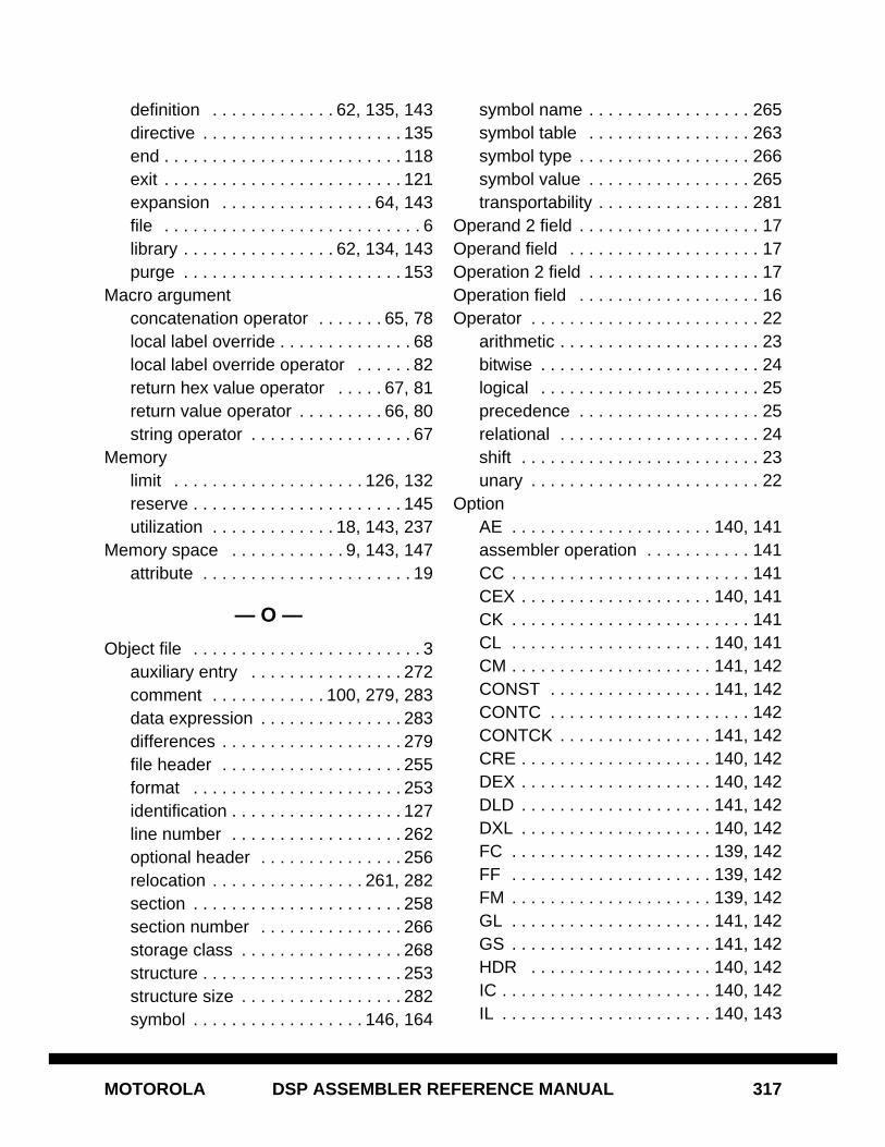
MOTOROLA DSP ASSEMBLER REFERENCE MANUAL 317
definition . . . . . . . . . . . . . 62, 135, 143directive . . . . . . . . . . . . . . . . . . . . . 135end . . . . . . . . . . . . . . . . . . . . . . . . . 118exit . . . . . . . . . . . . . . . . . . . . . . . . . 121expansion . . . . . . . . . . . . . . . . 64, 143file . . . . . . . . . . . . . . . . . . . . . . . . . . . 6library . . . . . . . . . . . . . . . . 62, 134, 143purge . . . . . . . . . . . . . . . . . . . . . . . 153
Macro argumentconcatenation operator . . . . . . . 65, 78local label override . . . . . . . . . . . . . . 68local label override operator . . . . . . 82return hex value operator . . . . . 67, 81return value operator . . . . . . . . . 66, 80string operator . . . . . . . . . . . . . . . . . 67
Memorylimit . . . . . . . . . . . . . . . . . . . . 126, 132reserve . . . . . . . . . . . . . . . . . . . . . . 145utilization . . . . . . . . . . . . . 18, 143, 237
Memory space . . . . . . . . . . . . 9, 143, 147attribute . . . . . . . . . . . . . . . . . . . . . . 19
— O —
Object file . . . . . . . . . . . . . . . . . . . . . . . . 3auxiliary entry . . . . . . . . . . . . . . . . 272comment . . . . . . . . . . . . 100, 279, 283data expression . . . . . . . . . . . . . . . 283differences . . . . . . . . . . . . . . . . . . . 279file header . . . . . . . . . . . . . . . . . . . 255format . . . . . . . . . . . . . . . . . . . . . . 253identification . . . . . . . . . . . . . . . . . . 127line number . . . . . . . . . . . . . . . . . . 262optional header . . . . . . . . . . . . . . . 256relocation . . . . . . . . . . . . . . . . 261, 282section . . . . . . . . . . . . . . . . . . . . . . 258section number . . . . . . . . . . . . . . . 266storage class . . . . . . . . . . . . . . . . . 268structure . . . . . . . . . . . . . . . . . . . . . 253structure size . . . . . . . . . . . . . . . . . 282symbol . . . . . . . . . . . . . . . . . . 146, 164
symbol name . . . . . . . . . . . . . . . . . 265symbol table . . . . . . . . . . . . . . . . . 263symbol type . . . . . . . . . . . . . . . . . . 266symbol value . . . . . . . . . . . . . . . . . 265transportability . . . . . . . . . . . . . . . . 281
Operand 2 field . . . . . . . . . . . . . . . . . . . 17Operand field . . . . . . . . . . . . . . . . . . . . 17Operation 2 field . . . . . . . . . . . . . . . . . . 17Operation field . . . . . . . . . . . . . . . . . . . 16Operator . . . . . . . . . . . . . . . . . . . . . . . . 22
arithmetic . . . . . . . . . . . . . . . . . . . . . 23bitwise . . . . . . . . . . . . . . . . . . . . . . . 24logical . . . . . . . . . . . . . . . . . . . . . . . 25precedence . . . . . . . . . . . . . . . . . . . 25relational . . . . . . . . . . . . . . . . . . . . . 24shift . . . . . . . . . . . . . . . . . . . . . . . . . 23unary . . . . . . . . . . . . . . . . . . . . . . . . 22
OptionAE . . . . . . . . . . . . . . . . . . . . . 140, 141assembler operation . . . . . . . . . . . 141CC . . . . . . . . . . . . . . . . . . . . . . . . . 141CEX . . . . . . . . . . . . . . . . . . . . 140, 141CK . . . . . . . . . . . . . . . . . . . . . . . . . 141CL . . . . . . . . . . . . . . . . . . . . . 140, 141CM . . . . . . . . . . . . . . . . . . . . . 141, 142CONST . . . . . . . . . . . . . . . . . 141, 142CONTC . . . . . . . . . . . . . . . . . . . . . 142CONTCK . . . . . . . . . . . . . . . . 141, 142CRE . . . . . . . . . . . . . . . . . . . . 140, 142DEX . . . . . . . . . . . . . . . . . . . . 140, 142DLD . . . . . . . . . . . . . . . . . . . . 141, 142DXL . . . . . . . . . . . . . . . . . . . . 140, 142FC . . . . . . . . . . . . . . . . . . . . . 139, 142FF . . . . . . . . . . . . . . . . . . . . . 139, 142FM . . . . . . . . . . . . . . . . . . . . . 139, 142GL . . . . . . . . . . . . . . . . . . . . . 141, 142GS . . . . . . . . . . . . . . . . . . . . . 141, 142HDR . . . . . . . . . . . . . . . . . . . 140, 142IC . . . . . . . . . . . . . . . . . . . . . . 140, 142IL . . . . . . . . . . . . . . . . . . . . . . 140, 143
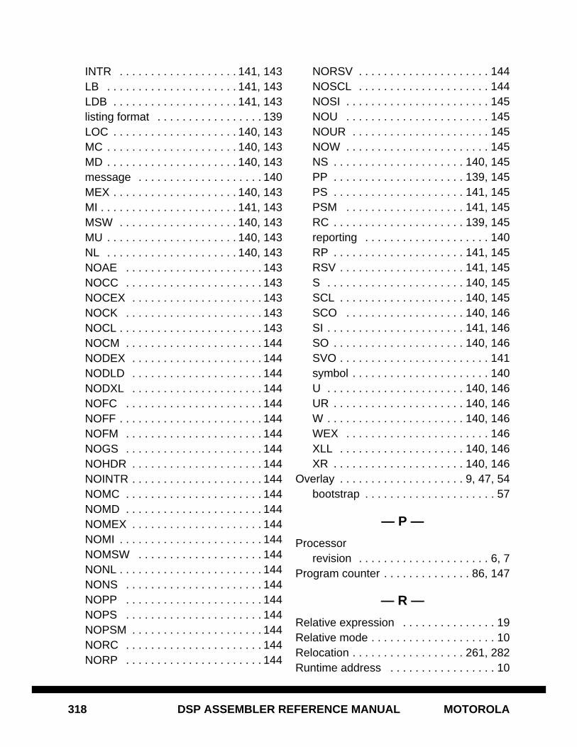
318 DSP ASSEMBLER REFERENCE MANUAL MOTOROLA
INTR . . . . . . . . . . . . . . . . . . . 141, 143LB . . . . . . . . . . . . . . . . . . . . . 141, 143LDB . . . . . . . . . . . . . . . . . . . . 141, 143listing format . . . . . . . . . . . . . . . . . 139LOC . . . . . . . . . . . . . . . . . . . . 140, 143MC . . . . . . . . . . . . . . . . . . . . . 140, 143MD . . . . . . . . . . . . . . . . . . . . . 140, 143message . . . . . . . . . . . . . . . . . . . . 140MEX . . . . . . . . . . . . . . . . . . . . 140, 143MI . . . . . . . . . . . . . . . . . . . . . . 141, 143MSW . . . . . . . . . . . . . . . . . . . 140, 143MU . . . . . . . . . . . . . . . . . . . . . 140, 143NL . . . . . . . . . . . . . . . . . . . . . 140, 143NOAE . . . . . . . . . . . . . . . . . . . . . . 143NOCC . . . . . . . . . . . . . . . . . . . . . . 143NOCEX . . . . . . . . . . . . . . . . . . . . . 143NOCK . . . . . . . . . . . . . . . . . . . . . . 143NOCL . . . . . . . . . . . . . . . . . . . . . . . 143NOCM . . . . . . . . . . . . . . . . . . . . . . 144NODEX . . . . . . . . . . . . . . . . . . . . . 144NODLD . . . . . . . . . . . . . . . . . . . . . 144NODXL . . . . . . . . . . . . . . . . . . . . . 144NOFC . . . . . . . . . . . . . . . . . . . . . . 144NOFF . . . . . . . . . . . . . . . . . . . . . . . 144NOFM . . . . . . . . . . . . . . . . . . . . . . 144NOGS . . . . . . . . . . . . . . . . . . . . . . 144NOHDR . . . . . . . . . . . . . . . . . . . . . 144NOINTR . . . . . . . . . . . . . . . . . . . . . 144NOMC . . . . . . . . . . . . . . . . . . . . . . 144NOMD . . . . . . . . . . . . . . . . . . . . . . 144NOMEX . . . . . . . . . . . . . . . . . . . . . 144NOMI . . . . . . . . . . . . . . . . . . . . . . . 144NOMSW . . . . . . . . . . . . . . . . . . . . 144NONL . . . . . . . . . . . . . . . . . . . . . . . 144NONS . . . . . . . . . . . . . . . . . . . . . . 144NOPP . . . . . . . . . . . . . . . . . . . . . . 144NOPS . . . . . . . . . . . . . . . . . . . . . . 144NOPSM . . . . . . . . . . . . . . . . . . . . . 144NORC . . . . . . . . . . . . . . . . . . . . . . 144NORP . . . . . . . . . . . . . . . . . . . . . . 144
NORSV . . . . . . . . . . . . . . . . . . . . . 144NOSCL . . . . . . . . . . . . . . . . . . . . . 144NOSI . . . . . . . . . . . . . . . . . . . . . . . 145NOU . . . . . . . . . . . . . . . . . . . . . . . 145NOUR . . . . . . . . . . . . . . . . . . . . . . 145NOW . . . . . . . . . . . . . . . . . . . . . . . 145NS . . . . . . . . . . . . . . . . . . . . . 140, 145PP . . . . . . . . . . . . . . . . . . . . . 139, 145PS . . . . . . . . . . . . . . . . . . . . . 141, 145PSM . . . . . . . . . . . . . . . . . . . 141, 145RC . . . . . . . . . . . . . . . . . . . . . 139, 145reporting . . . . . . . . . . . . . . . . . . . . 140RP . . . . . . . . . . . . . . . . . . . . . 141, 145RSV . . . . . . . . . . . . . . . . . . . . 141, 145S . . . . . . . . . . . . . . . . . . . . . . 140, 145SCL . . . . . . . . . . . . . . . . . . . . 140, 145SCO . . . . . . . . . . . . . . . . . . . 140, 146SI . . . . . . . . . . . . . . . . . . . . . . 141, 146SO . . . . . . . . . . . . . . . . . . . . . 140, 146SVO . . . . . . . . . . . . . . . . . . . . . . . . 141symbol . . . . . . . . . . . . . . . . . . . . . . 140U . . . . . . . . . . . . . . . . . . . . . . 140, 146UR . . . . . . . . . . . . . . . . . . . . . 140, 146W . . . . . . . . . . . . . . . . . . . . . . 140, 146WEX . . . . . . . . . . . . . . . . . . . . . . . 146XLL . . . . . . . . . . . . . . . . . . . . 140, 146XR . . . . . . . . . . . . . . . . . . . . . 140, 146
Overlay . . . . . . . . . . . . . . . . . . . . 9, 47, 54bootstrap . . . . . . . . . . . . . . . . . . . . . 57
— P —
Processorrevision . . . . . . . . . . . . . . . . . . . . . 6, 7
Program counter . . . . . . . . . . . . . . 86, 147
— R —
Relative expression . . . . . . . . . . . . . . . 19Relative mode . . . . . . . . . . . . . . . . . . . . 10Relocation . . . . . . . . . . . . . . . . . . 261, 282Runtime address . . . . . . . . . . . . . . . . . 10
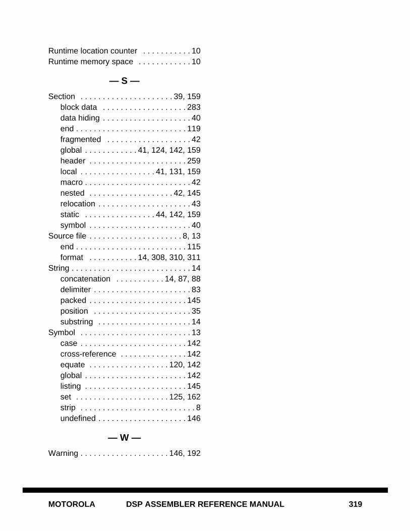
MOTOROLA DSP ASSEMBLER REFERENCE MANUAL 319
Runtime location counter . . . . . . . . . . . 10Runtime memory space . . . . . . . . . . . . 10
— S —
Section . . . . . . . . . . . . . . . . . . . . . 39, 159block data . . . . . . . . . . . . . . . . . . . 283data hiding . . . . . . . . . . . . . . . . . . . . 40end . . . . . . . . . . . . . . . . . . . . . . . . . 119fragmented . . . . . . . . . . . . . . . . . . . 42global . . . . . . . . . . . . 41, 124, 142, 159header . . . . . . . . . . . . . . . . . . . . . . 259local . . . . . . . . . . . . . . . . . 41, 131, 159macro . . . . . . . . . . . . . . . . . . . . . . . . 42nested . . . . . . . . . . . . . . . . . . . 42, 145relocation . . . . . . . . . . . . . . . . . . . . . 43static . . . . . . . . . . . . . . . . 44, 142, 159symbol . . . . . . . . . . . . . . . . . . . . . . . 40
Source file . . . . . . . . . . . . . . . . . . . . . 8, 13end . . . . . . . . . . . . . . . . . . . . . . . . . 115format . . . . . . . . . . . 14, 308, 310, 311
String . . . . . . . . . . . . . . . . . . . . . . . . . . . 14concatenation . . . . . . . . . . . 14, 87, 88delimiter . . . . . . . . . . . . . . . . . . . . . . 83packed . . . . . . . . . . . . . . . . . . . . . . 145position . . . . . . . . . . . . . . . . . . . . . . 35substring . . . . . . . . . . . . . . . . . . . . . 14
Symbol . . . . . . . . . . . . . . . . . . . . . . . . . 13case . . . . . . . . . . . . . . . . . . . . . . . . 142cross-reference . . . . . . . . . . . . . . . 142equate . . . . . . . . . . . . . . . . . . 120, 142global . . . . . . . . . . . . . . . . . . . . . . . 142listing . . . . . . . . . . . . . . . . . . . . . . . 145set . . . . . . . . . . . . . . . . . . . . . 125, 162strip . . . . . . . . . . . . . . . . . . . . . . . . . . 8undefined . . . . . . . . . . . . . . . . . . . . 146
— W —
Warning . . . . . . . . . . . . . . . . . . . . 146, 192