Embed Size (px)
Citation preview

Design, Manufacture and Installation of Theatrical Equipment Worldwide
(315) 451-3440 Fax (315) 451-1766 www.jrclancy.com
Motorized Rigging Control System Operating Instructions
© 2011 J.R, Clancy, Inc.

Altus Motorized Rigging Control System – Operation Manual Page 2
Design, Manufacture and Installation of Theatrical Equipment Worldwide (315) 451-3440 Fax (315) 451-1766 www.jrclancy.com
Rev 2: 16 February 2011
Table of Contents
IMPORTANT NOTES ................................................................................................................... 3
INTRODUCTION: CONTROL SYSTEM OVERVIEW .................................................................. 4
CONTROL SYSTEM COMPONENTS .......................................................................................... 4 EMERGENCY STOP SYSTEM ............................................................................................................... 4 WINCH CONTROLLERS ........................................................................................................................ 5 LIMIT SWITCHES ................................................................................................................................... 5
END-OF-TRAVEL LIMITS .................................................................................................................................... 5 LIMIT SWITCH TYPES ........................................................................................................................................ 6
LOGIC CABINET ..................................................................................................................................... 6 PROFIBUS COMMUNICATIONS BUS ................................................................................................... 6 CONTROL CONSOLE ............................................................................................................................ 7 PORTABLE CONTROL PENDANT ......................................................................................................... 7
SYSTEM OPERATION ................................................................................................................. 8 WARNING SCREEN ............................................................................................................................... 8 PASSWORD PROTECTION OF SYSTEM FUNCTIONS ........................................................................ 8 WINCH BASE SCREEN ........................................................................................................................ 10
WINCH OPERATION- DIRECT CONTROL ...................................................................................................... 10 WINCH OPERATION- TARGET CONTROL ..................................................................................................... 11 MULTIPLE WINCHES ........................................................................................................................................ 12 WINCH OPERATION- CUE PLAYBACK ........................................................................................................... 13 CUE SEQUENCING .......................................................................................................................................... 14 RECORDING CUES .......................................................................................................................................... 14 CUE EDITING .................................................................................................................................................... 15 CUE LIST EDITING............................................................................................................................................ 15
WINCH STATUS PAGE ........................................................................................................................ 16 BUS DIAGNOSIS PAGE ....................................................................................................................... 18 WINCH PARAMETER PAGE ................................................................................................................ 18 SHOW PAGE ........................................................................................................................................ 22
LOAD A SHOW .................................................................................................................................................. 22 DELETE A SHOW .............................................................................................................................................. 23 DELETE SHOW CUES ...................................................................................................................................... 23 COPY A SHOW .................................................................................................................................................. 23 RENAME A SHOW ............................................................................................................................................ 23
APPENDIX I: LOAD MONITORING ........................................................................................... 24
APPENDIX II: PORTABLE PENDANT OPERATION ................................................................ 25 SETS PAGE .......................................................................................................................................... 26 CUE PAGE ............................................................................................................................................ 27
Altus Motorized Rigging Control System – Operation Manual Page 3
Design, Manufacture and Installation of Theatrical Equipment Worldwide (315) 451-3440 Fax (315) 451-1766 www.jrclancy.com
Rev 2: 16 February 2011
Anyone entering a building with public access has reason to expect that he or she is safe from harm by the building itself and by the equipment and activities within the building. It is the legal responsibility of the owner and designated manager to ensure that this expectation is met. It is the responsibility of the owner to hire and train competent people. A competent person is defined as one who is capable of identifying existing and predictable hazards in the workplace and who has the authority to take prompt corrective action to eliminate those hazards. It is the further responsibility of the owner and designated manager to provide a safe working environment for all employees, including proper equipment, training on the use of equipment, and written procedures for its use and maintenance. It is also important to keep all unauthorized and/or untrained personnel from the working areas of the stage. Before operating any stage equipment, operators must be given the necessary training and must then work only under the direction of qualified supervisors. Operators of the equipment must: Learn the feel, sound, and smell of equipment to immediately sense when something is not correct. Study the capacities and capabilities of each system and its components. Thoroughly learn and practice the proper operating procedures. Before operating any equipment, ask questions about the current condition of equipment and about
any existing conditions which may affect proper operation or which could be affected by its operation. For example, is anything fouling the equipment or in the path of its intended travel?
Any problem noticed during setup or operation of the stage equipment should be corrected IMMEDIATELY. In accordance with OSHA standard 29 CFR 1926.550, ANSI/ESTA Standard E 1.4-2009 (where applicable), and the terms of J.R. Clancy’s warranty, a qualified rigging firm must perform yearly inspections and correct any deficiencies discovered. These firms have personnel who are trained to spot present hazards and many "potential" hazards. A routine maintenance and inspection schedule must be established and followed, with appropriate records maintained. Routine maintenance prolongs the useful life of equipment and keeps it operating at peak efficiency for the easiest and quietest possible operation.
Important notes
WARNING! Improper use of rigging equipment can result in serious injury. Do not operate without proper
training and authorization. Do not use rigging equipment for lifting people.
DISCLAIMER The information in this manual will not cover all possible situations, nor could such inclusive
instructions be written by the equipment manufacturer, due to the various processes of mounting theatrical performances. This manual is intended to provide a guide to the safe and efficient
operation of the furnished stage equipment and its routine maintenance. No manual can replace your duty to exercise constant vigilance and common sense. J.R. Clancy will not be responsible
for any damage that results from failure to comply with this manual.

Altus Motorized Rigging Control System – Operation Manual Page 4
Design, Manufacture and Installation of Theatrical Equipment Worldwide (315) 451-3440 Fax (315) 451-1766 www.jrclancy.com
Rev 2: 16 February 2011
The Altus Motorized Rigging Control system uses industrial-grade components, operating on a proven factory automation platform, to safely and accurately control motorized equipment in a performance space. This system includes the following subsystems:
• A hard-wired emergency stop system, which can be used to immediately stop all machines under system control. The term “emergency stop” will frequently be abbreviated as “E-stop” in this manual.
• A logic cabinet, housing an industrial-grade Programmable Logic Controller (PLC), which gathers and stores the system data and sends commands to the individual winch controllers. The Logic Cabinet also contains the power supply for DC power, which serves as a control voltage source for various system functions.
• The PROFIBUS communications network, which carries commands from the PLC to the individual winch controllers, and returns status information on the controlled winches
• Winch controllers, which receive commands from and send status information to the PLC. Each winch controller works with inputs from the motorized rigging equipment (including hardware limit switches, position encoders, load cells and other safety devices), and controls the motor speed and direction appropriately to fulfill the PLC’s commands. Note that the Altus control system may be used to control hoisting winches, traveler curtains, lifting platforms, or other motorized stage equipment; therefore, the term “winch” is used throughout this manual to refer to any motorized equipment under Altus control.
• The Altus control console, which features a 12” touchscreen PC for display of system status and selection of system functions, a set of hardwired pushbuttons for carrying out movement commands, a joystick for varying the speed of motors with variable-speed controllers, an Emergency Stop button, and a system power keyswitch.
• Other optional system components, including a portable control pendant with flexible cord and receptacle stations, remote E-stop stations, door interlocks or other safety devices.
• Throughout this manual, the word “winch” will be used to describe a motorized drive system. Most often, winches are used for hoisting applications; however, the Altus system may also be used to control lifting platforms, traveler curtains, curtain pocket doors, wagons, or other devices.
EMERGENCY STOP SYSTEM The emergency stop system is activated through latching mushroom-head emergency stop buttons in the control system, located as required throughout the performance space. The E-
Introduction: Control System Overview
Control System Components

Altus Motorized Rigging Control System – Operation Manual Page 5
Design, Manufacture and Installation of Theatrical Equipment Worldwide (315) 451-3440 Fax (315) 451-1766 www.jrclancy.com
Rev 2: 16 February 2011
stop buttons are joined in a series loop; pushing any of the buttons will break the loop, and signal an emergency stop condition. Pressing an E-stop button will bring all motors in the system to a rapid stop, by turning off the control power to each winch controller. Pressing the E-stop button will also signal the PLC that an emergency stop condition exists. The E-stop buttons latch when pressed. To release a non-illuminated E-stop button, turn the button one-quarter turn clockwise (as indicated by arrows on the button) and allow the button to pop out. To release an illuminated E-stop button, pull the button out.
WINCH CONTROLLERS Each winch axis includes a controller, which communicates with the system Programmable Logic Controller. The winch controller contains circuit protection and electronic motor control devices. In variable-speed winches, each controller includes a vector inverter drive, which takes in data from the motor encoder and winch limit switches, provides brake release signals, regulates the motor direction and speed, and communicates with the PLC. The vector inverter drive incorporates motor protection functions, including overload sensing, and provides fault status information. Fixed-speed controllers include a reversing starter with circuit and motor overload protection. Depending on the requirements of the system, a fixed-speed controller may include a self-contained micro-PLC with communication module, or a set of remote input/output modules with an interface module that integrates them into the central PLC. If a winch is equipped with load-monitoring, load cells will be mounted appropriately to sense the weight of the hoisted load (for example, at the winch headblock). The load cells are connected to a load cell amplifier, whose output is connected to an analog input on the inverter (variable-speed axes) or micro-PLC (fixed-speed axes).
LIMIT SWITCHES
END-OF-TRAVEL LIMITS Each axis is equipped with end-of-travel limit switches. End-of-travel limits are classified by their function, either as normal limits or overtravel limits. The normal limits stop motion in the selected direction, but permit motion in the opposite direction. Each normal limit is paired with an overtravel (or ultimate) limit; striking an overtravel limit will remove control power to the controller, preventing all motion of the winch. Striking an overtravel limit is an abnormal situation! A careful inspection of the winch must be conducted to determine why an overtravel limit switch was activated. A maintenance procedure is required to clear this condition and restore normal operation. Variable-speed, or inverter-controlled, winches are programmed to “bounce off” of normal end-of-travel limit switches. Upon striking a normal up or down limit switch, the winch will immediately stop, pausing briefly before slowly moving in the opposite direction until clear of the limit switch. During this “creep” period, the inverter status may indicate a fault and the winch will be unresponsive to normal controls. When the winch is clear of the limit switch, normal operation can resume.

Altus Motorized Rigging Control System – Operation Manual Page 6
Design, Manufacture and Installation of Theatrical Equipment Worldwide (315) 451-3440 Fax (315) 451-1766 www.jrclancy.com
Rev 2: 16 February 2011
Both normal limits and overtravel limits are tied into the system control in all modes of operation- from the main control system, maintenance controls on a motor control cabinet, and from a maintenance pendant.
LIMIT SWITCH TYPES Limit switch functions can be accomplished either with rotary or direct-struck limit switches. Rotary limit switches are mechanically coupled to the winch drive mechanism. Each rotary limit switch has four elements (up overtravel, up, down, and down overtravel) that rotate in unison, using a tooth-like bump to strike a switch. Direct-struck limit switches are struck by a piece of the driven mechanism (e.g. a moving drum flange or a cam mounted on the counterweight arbor, cable clew, or lift guide).
LOGIC CABINET The system Logic Cabinet contains the system Programmable Logic Controller (PLC). This industrial-grade dedicated-purpose computer gathers and stores system data, including inputs from the console touchscreen and control devices. The PLC communicates with the winch controllers via PROFIBUS, a high-speed data communication system developed to provide reliable and accurate control of factory automation systems. The logic cabinet also includes the 24 volt DC system power supply and associated fusing and switching. The power supply provides control power for a variety of system control functions, including the system control busses (AUX, COM, ES and SYS). The console receptacle is wired back to the logic cabinet. In many cases, the receptacle is mounted directly on the logic cabinet itself.
PROFIBUS COMMUNICATIONS BUS System data and commands are carried between the PLC and the winch controllers over a PROFIBUS communication network. PROFIBUS requires daisy-chain topography, with each node requiring an input connection from the PLC or the previous node and supplying an output to the next node in the chain. No branches, tees, or loops are permitted. A winch that plugs into a control raceway uses two PROFIBUS runs – one for the input, and the other for the output. If the winch is unplugged from the raceway, a shunt plug must be inserted into the receptacle to continue the bus to its proper termination. Two linear PROFIBUS segments may be joined with a repeater. The placement and configuration of repeaters is carefully considered during the project planning phase. They are placed to control the length of PROFIBUS segments, and to provide for connections to peripheral points. A PROFIBUS segment must be terminated with an active terminating device at both ends. PROFIBUS cabling is specifically engineered for extremely high data transmission rates. Only cable which is certified for use in PROFIBUS-DP applications may be used for this network.

Altus Motorized Rigging Control System – Operation Manual Page 7
Design, Manufacture and Installation of Theatrical Equipment Worldwide (315) 451-3440 Fax (315) 451-1766 www.jrclancy.com
Rev 2: 16 February 2011
CONTROL CONSOLE The Altus control console is the main user interface for the motorized rigging system. The base
Altus console is desk-mounted; optional configurations permit it to be mounted on a roll-about pedestal or wall-mounted. It contains the following controls: POWER keyswitch – at the front edge of the console, left. Used to turn the control system power on or off. Key can only be removed when switch in the off position. EMERGENCY STOP - red latching mushroom-head button pushed in to initiate an emergency stop condition, released to enable normal system operation. UP, DOWN, and GO TARGET buttons - momentary-action “dead man” buttons pushed and held to execute an action, previously selected on the display screen.
SPEED - spring-return-to-center joystick control, used to speed up or slow down the execution of an action (variable-speed systems only). DISPLAY - the touchscreen display contains the control selections and status displays to operate the system. The following sections of this manual detail operation of the system through the use of the display screen pages.
PORTABLE CONTROL PENDANT Some Altus systems use a portable control pendant as an auxiliary control point. The pendant is equipped with a cable (usually 10m or 30’ long, but optionally as much as 25m long). This cable is plugged into designated pendant receptacles. The features and controls of the portable control pendant are as follows:
1. Rotary operator 2. Emergency Stop button 3. Liquid Crystal Display (5.7”
diag. touchscreen) 4. Membrane type function keys 5. Keyswitch operator
Function keys on the left of the screen are used to control motion, rather than the panel-mounted pushbuttons. The upper left button is GO UP, the button
Altus Motorized Rigging Control System – Operation Manual Page 8
Design, Manufacture and Installation of Theatrical Equipment Worldwide (315) 451-3440 Fax (315) 451-1766 www.jrclancy.com
Rev 2: 16 February 2011
immediately below that is GO DOWN, and the bottom button on the left side is GO TARGET. Like the console pushbuttons, the function keys also operate in “dead man” mode. The keys must be pushed and held to initiate and maintain motion; releasing the keys will cause the move to stop. The pendant operating screens are described in Appendix II. In systems with a pendant station, the pendant will take priority. While the pendant is plugged in, the pushbuttons on the console are disabled and will not operate until the pendant is unplugged. A flag will appear on the console touchscreen, reading PENDANT PLUGGED, to tell the operator why the console inputs are disabled. While the pendant is plugged in, its Emergency Stop button is part of the E-stop loop; the pendant E-stop button must be released to allow motion of any axis. When the pendant is unplugged, the E-stop circuit is automatically shunted to restore the E-stop loop. Pendant plugs have a red coding dot to indicate the proper orientation of the plug. While facing the front of the receptacle station, hold the plug with the dot facing you, and insert the plug directly, without twisting. To remove the plug from the receptacle, grasp the plug by the knurled ridges and pull the plug straight out – these ridges are attached to a latching mechanism; pulling on the plug by any other part will not release the latch.
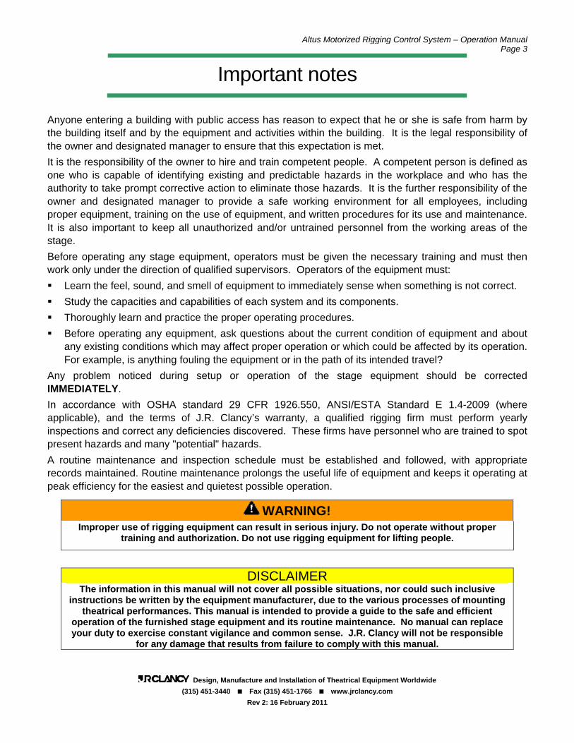
WARNING SCREEN When the system is first powered up, it goes through a boot-up procedure involving several screens as the software loads. At the conclusion of its boot sequence, the opening screen is displayed. Once this warning has been read and understood, touch the ACCEPT button on the screen to proceed to the winch base screen. The green indicator at the lower left of the screen is a Service Timer. This indicator will turn red one year after system startup, to indicate that it is time to have the rigging system inspected by a qualified rigging inspector. When this
inspection is completed, the inspector will reset the indicator.
PASSWORD PROTECTION OF SYSTEM FUNCTIONS Basic system operation does not require a password. This includes direct and target operation of winches, and loading and running pre-recorded cues. There are a number of system functions which are protected by passwords. There are three levels of password protection:
System Operation

Altus Motorized Rigging Control System – Operation Manual Page 9
Design, Manufacture and Installation of Theatrical Equipment Worldwide (315) 451-3440 Fax (315) 451-1766 www.jrclancy.com
Rev 2: 16 February 2011
User-level password privileges are mainly required to record cues, to edit the cue list, and to turn load monitoring on and off. Edit level password privileges are mainly required to create, delete, or change shows, and to set show soft limits and deads. System level password privileges are required for system setup functions by factory-designated personnel. The password levels are hierarchical; that is, an operator logged in at the user level can perform user-level functions; an operator logged in at the edit level can perform edit-level or user-level functions, and an operator logged in at the system level can perform all password-protected functions. When using a password-protected function, the operator should log in at the minimum required level, to avoid making inadvertent changes to higher level parameters and values. When an operator is not logged in (or is logged in at a lower password level) touching a password-protected button or field will bring up the user and password entry pane, and an on-
screen keyboard. The operator must touch the USER: name field to make it active, then type in the name of the desired log-in level (user, edit or system). The operator then touches the PASSWORD: entry field to make it active and types in the appropriate password. The operator must touch the OK button on the login pane to make the password active. The operator can then touch the password-
protected button or field again to proceed with using it. NOTE: All screens that have password-protected functions also have a place where the current password level is shown, just below a LOG OUT button. When the operator is done with the password-protected operation, the LOG OUT button should be used. This will renew the password protection, so that these functions cannot be changed inadvertently or by unauthorized personnel.

Altus Motorized Rigging Control System – Operation Manual Page 10
Design, Manufacture and Installation of Theatrical Equipment Worldwide (315) 451-3440 Fax (315) 451-1766 www.jrclancy.com
Rev 2: 16 February 2011
WINCH BASE SCREEN The winch base screen is the main user interface for the control system. The EMERG STOP indicator at the top center of the screen will be green if the emergency stop system is healthy, or
will turn red if an emergency stop button has been pressed. When entering this page, the SETS indicator at the upper right is illuminated. The list below this indicator contains the sets in the system. Each set has a channel number field and a set name field. If there are more than twelve sets in the system, the PAGE DN and PAGE UP buttons will navigate through multiple pages of sets.
WINCH OPERATION-
DIRECT CONTROL To select a winch for operation, touch the winch name or the channel number. The channel field will turn yellow to indicate that the winch has been selected, and the winch data will appear
in the active cue list at the left of the screen. In the illustration, the House Curtain set (channel 2) has been selected for operation. The selected winch may now be run up (toward its soft upper limit) or down (toward its soft lower limit) using the GO UP or GO DOWN buttons on the console. A variable-speed winch will operate at its default speed. While running, the SPEED joystick may be used to vary the speed of a variable-speed set – pushing the joystick up increases speed, pulling it down decreases speed, a return to center will
return the set to its default speed.

Altus Motorized Rigging Control System – Operation Manual Page 11
Design, Manufacture and Installation of Theatrical Equipment Worldwide (315) 451-3440 Fax (315) 451-1766 www.jrclancy.com
Rev 2: 16 February 2011
NOTE: Operation of all machinery controlled by this system is under “dead man” operation. In this type of operation, the operator must press and hold a physical button to run a set; releasing the button causes the winches/equipment to stop. This is done to assure that the operator may not initiate a move and then leave the operator station while the move is in progress. Fields in the active cue list indicate status information about the selected winch. The POS field indicates the current position of the winch and the TRGT field indicates a winch target. If the winch target is set for a pre-determined “dead” (preset position), the name of that “dead” will appear in the DEAD field. For winches equipped with load monitoring, the LOAD field indicates the current load imposed on the winch, including the batten and suspended equipment. For variable speed winches, the default speed (or entered speed) of the winch will appear in the SPD field. The TIME field indicates how many seconds is required to move the batten (at the designated speed) from the current position to the designated target. Additional axes may be added to the active cue list by touching the channel number or the name of the winch in the Sets list. After one winch has been selected, the SET FILL button may be used to select all subsequent winches (up to the maximum number allowed in the active cue list- the maximum number is determined during system startup). An individual winch may be de-selected by touching (and highlighting) the winch name in the active cue list, then touching the CLR SLCT button. All of the winches may be removed from the active cue list by touching the CLR ALL button. It is also possible to change one winch in the active cue list for another, by touching the NMBR field for a winch in the active cue list, then keying in the motor number of the desired winch when the on-screen keypad pops up. WARNING: Never move a unit which you, the operator, do not have in direct view. Damage or injury may occur if a unit is moved without first checking that the unit is clear to move. If you cannot maintain a clear view of the unit throughout the move, arrange to have spotters located where they can see and have a reliable way of communicating with them throughout the move.
WINCH OPERATION- TARGET CONTROL To designate a target for winch operation, first add the winch to the active cue list by touching the winch name in the Sets list as described in the previous section. Once the desired winch is in the active cue list, touch the TRGT field to open the target window for that winch. This window may also be opened by touching the SPD, TIME or DEAD fields.
Once this window is open, touch the TRGT field to open a numeric keypad. Key in the desired target (in decimal feet), and press the Enter key to enter the new target. A “dead” (pre-determined target) may be entered as the target by touching the desired DEADS field; the associated target will appear in the TRGT field and the name of the dead will appear in the SELECTED DEAD field.
For variable-speed winches, the desired speed may be entered by touching the FPM (feet per minute), %MAX (percentage of full speed), or TIME (time in seconds to target) field. Speeds
Altus Motorized Rigging Control System – Operation Manual Page 12
Design, Manufacture and Installation of Theatrical Equipment Worldwide (315) 451-3440 Fax (315) 451-1766 www.jrclancy.com
Rev 2: 16 February 2011
outside the normal operating range of the winches are automatically altered to a value in range. In addition, the acceleration time and deceleration time may be changed by touching the ACCEL or DECEL field and entering a new value. Changing any of these fields will recalculate all of these speed-related fields. Changing these values for a selected winch will affect the winch’s performance in direct up and down moves as well as in target moves. NOTE: Default values for acceleration and deceleration times have been set during system startup. These values may be changed, but consider the following: Extremely short acceleration and deceleration times may result in drive faults due to excessive current draw – this is particularly true for heavily loaded sets. Extremely long deceleration times can lead to winches continuing to travel long after the operator expects them to stop (in dead-man moves). Make sure to rehearse any moves involving altered acceleration and deceleration values before running them in a show! Once a target has been designated, the winch may be run to that target by pushing and holding the GO TARGET button on the control console. The winch will accelerate to the designated speed and travel until it reaches the target. If the GO TARGET button is released before the winch reaches the target, the winch will decelerate to a stop. The speed of variable-speed winches may be varied by using the joystick as described under Direct Control, above. Fixed-speed units will only operate at their designated speed.
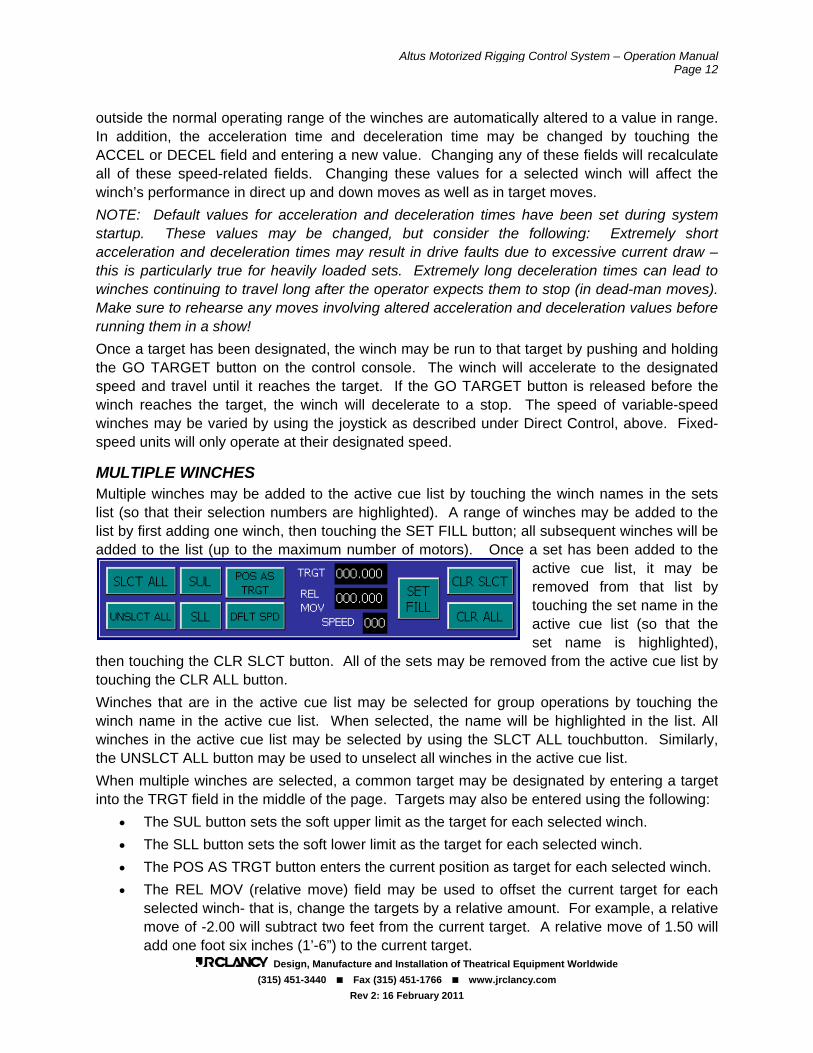
MULTIPLE WINCHES Multiple winches may be added to the active cue list by touching the winch names in the sets list (so that their selection numbers are highlighted). A range of winches may be added to the list by first adding one winch, then touching the SET FILL button; all subsequent winches will be added to the list (up to the maximum number of motors). Once a set has been added to the
active cue list, it may be removed from that list by touching the set name in the active cue list (so that the set name is highlighted),
then touching the CLR SLCT button. All of the sets may be removed from the active cue list by touching the CLR ALL button. Winches that are in the active cue list may be selected for group operations by touching the winch name in the active cue list. When selected, the name will be highlighted in the list. All winches in the active cue list may be selected by using the SLCT ALL touchbutton. Similarly, the UNSLCT ALL button may be used to unselect all winches in the active cue list. When multiple winches are selected, a common target may be designated by entering a target into the TRGT field in the middle of the page. Targets may also be entered using the following:
• The SUL button sets the soft upper limit as the target for each selected winch. • The SLL button sets the soft lower limit as the target for each selected winch. • The POS AS TRGT button enters the current position as target for each selected winch. • The REL MOV (relative move) field may be used to offset the current target for each
selected winch- that is, change the targets by a relative amount. For example, a relative move of -2.00 will subtract two feet from the current target. A relative move of 1.50 will add one foot six inches (1’-6”) to the current target.

Altus Motorized Rigging Control System – Operation Manual Page 13
Design, Manufacture and Installation of Theatrical Equipment Worldwide (315) 451-3440 Fax (315) 451-1766 www.jrclancy.com
Rev 2: 16 February 2011
When variable speed winches are selected, entering a new value into the SPEED field will assign the given speed into all selected winches, subject to the operating range of each winch. The DFLT SPD touchbutton can be used to assign each selected winch’s default speed. When a new speed is entered, the selected winches will operate at the new speed value (which will also be joystick’s center position) until they are removed from the active cue list.
WINCH OPERATION- CUE PLAYBACK A cue is a target move that has been recorded for later playback. It may include multiple
winches, and may involve multiple targets (and multiple speeds, for variable-speed winches). To select a cue for playback, first touch the CUES button at the top right of the screen. This button will illuminate and a list of cues will appear below. To load a cue for playback, touch the cue name or number in the cues list. When a cue is loaded, the cue number will be highlighted in the cues list and at the top left of the active cue list, and the cue name will appear at the top of the active cue list. The active cue list will display all of the winches involved in the cue,
along with the current position for each winch and the recorded target (and speed, where applicable) for the winch in that cue. The TIME field will display the time (in seconds) required for the winch to travel from its current position to the target position. Once a cue has been loaded, the winches in the cue may be run to their targets by pushing and holding the GO TARGET button on the control console. The winches will accelerate to the designated speeds and travel until they reach their targets. If the GO TARGET button is released before all winches reach their targets, the winches will decelerate and stop at
that point in their travel. The speed of all variable-speed winches in the cue may be varied by using the joystick, as described under Direct Control, above. If any part of the cue is modified while the cue is loaded (e.g. a target or speed is changed), the cue number will no longer be highlighted. At this point, all values from the loaded cue (including

Altus Motorized Rigging Control System – Operation Manual Page 14
Design, Manufacture and Installation of Theatrical Equipment Worldwide (315) 451-3440 Fax (315) 451-1766 www.jrclancy.com
Rev 2: 16 February 2011
values that were changed) are written to a temporary cue. The cue name will remain on display at the top of the list to indicate which base cue was the starting point for this current temporary cue. A cue may be unloaded at any time by touching the SETS button (top right corner) then the CLR ALL button (right center of screen). While a cue is loaded, the winches in the active cue list can only be operated by pressing the GO TARGET button. The GO UP and GO DOWN buttons are normally not active. However, the CUE SET EDIT button may be used to enable the GO UP and GO DOWN buttons while a cue is loaded. The CUE SET EDIT button is password-protected with the user-level password.
CUE SEQUENCING Each cue can sequence in a number of ways, determined by the fields and buttons found in the sequencing window below the active cue list. There are three basic types of cue sequencing possible: AUTO LOAD: (Active when illuminated) When the current cue is complete (all winches at the designated targets), the next cue will automatically load when the operator releases the GO TARGET button.
NO SEQUENCE: Indicated by dark AUTO FOLLOW and AUTO LOAD buttons. When the current cue completes, the current cue will remain loaded until another cue is manually selected from the cues list or the selected cue is de-selected from the cues list. This may be done by touching the SETS buttons then the CLR ALL button as described above. AUTO FOLLOW: (Active when illuminated) While the GO TARGET button is held, the next cue will begin a given amount of time after the current cue starts or completes. The timing is determined by the SEC field- some number of seconds- and the appropriate selection of either the AFTER CUE STARTS or AFTER CUE COMPLETES button. The TIMER field reflects the number of seconds remaining to complete the currently loaded cue. The maximum number of motors is programmed into the system when the system is first commissioned. If cascaded cues command more the maximum number of motors, then only the maximum number of motors will run – as a motor reaches its destination and stops, another will be permitted to run, until all have achieved their targets.
RECORDING CUES Cue recording is protected by the user-level password. Recording a cue involves a setup for each winch, then assigning the new cue a name and place in the cue order. Using the steps described above, perform the following steps:
1. With the Sets list displayed, select the winches to move in this cue.
2. Designate a target for each winch.
3. If a winch is variable-speed, designate additional parameters (speed, accel, decel).
4. Enter a name for the cue in the NAME field at the top left of the screen.
Altus Motorized Rigging Control System – Operation Manual Page 15
Design, Manufacture and Installation of Theatrical Equipment Worldwide (315) 451-3440 Fax (315) 451-1766 www.jrclancy.com
Rev 2: 16 February 2011
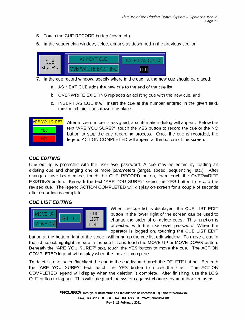
5. Touch the CUE RECORD button (lower left).
6. In the sequencing window, select options as described in the previous section.
7. In the cue record window, specify where in the cue list the new cue should be placed:
a. AS NEXT CUE adds the new cue to the end of the cue list,
b. OVERWRITE EXISTING replaces an existing cue with the new cue, and
c. INSERT AS CUE # will insert the cue at the number entered in the given field, moving all later cues down one place.
After a cue number is assigned, a confirmation dialog will appear. Below the text “ARE YOU SURE?”, touch the YES button to record the cue or the NO button to stop the cue recording process. Once the cue is recorded, the legend ACTION COMPLETED will appear at the bottom of the screen.
CUE EDITING Cue editing is protected with the user-level password. A cue may be edited by loading an existing cue and changing one or more parameters (target, speed, sequencing, etc.). After changes have been made, touch the CUE RECORD button, then touch the OVERWRITE EXISTING button. Beneath the text “ARE YOU SURE?” select the YES button to record the revised cue. The legend ACTION COMPLETED will display on-screen for a couple of seconds after recording is complete.
CUE LIST EDITING When the cue list is displayed, the CUE LIST EDIT button in the lower right of the screen can be used to change the order of or delete cues. This function is protected with the user-level password. When the operator is logged on, touching the CUE LIST EDIT
button at the bottom right of the screen will bring up the cue list edit window. To move a cue in the list, select/highlight the cue in the cue list and touch the MOVE UP or MOVE DOWN button. Beneath the “ARE YOU SURE?” text, touch the YES button to move the cue. The ACTION COMPLETED legend will display when the move is complete.
To delete a cue, select/highlight the cue in the cue list and touch the DELETE button. Beneath the “ARE YOU SURE?” text, touch the YES button to move the cue. The ACTION COMPLETED legend will display when the deletion is complete. After finishing, use the LOG OUT button to log out. This will safeguard the system against changes by unauthorized users.

Altus Motorized Rigging Control System – Operation Manual Page 16
Design, Manufacture and Installation of Theatrical Equipment Worldwide (315) 451-3440 Fax (315) 451-1766 www.jrclancy.com
Rev 2: 16 February 2011
WINCH STATUS PAGE The winch status page is accessed by touching the STATUS PAGE button in the lower left corner of the base screen. The EMERG STOP indicator at the top right of the screen will appear green if the emergency stop system is healthy or red if an E-stop button has been pressed. The page will open to show the status information for a selected winch. Different winches may be selected by entering a winch number in the SET NUMBER field or touching the INC and
DEC buttons to increase or decrease the set number. The set name will update to reflect the name of the selected winch.
Indicators on the status page reflect the following status information for the selected winch:
DRIVE READY: Green if there is power to the controller, grey if the controller is not powered. DRIVE REFED: Green if the controller is referenced (ready to operate), grey otherwise. AT POS: Green if the winch is at its target position, grey if the winch is away from its target. UP LIMIT: Yellow when the winch is on the normal up limit switch, grey if the winch is clear of the limit. DOWN LIMIT: Yellow when the winch is on the normal down limit switch, grey if clear of the limit.
DRIVE FAULT: Red to signify that an inverter drive fault has occurred. Faults must be reset to resume normal operation of the winch. (See DRIVE RESET below.) FAULT CODE: In the case of a drive fault (see above), this field will contain a numeric fault code. Contact the J.R. Clancy Controls Department with this number to diagnose the fault. DRIVE RESET: Touch to reset the inverter drive after a drive fault has occurred and the condition has been cleared. For winches equipped with load monitoring: LOAD FAULT: Fault occurring when a load is detected outside the programmed acceptable load window for the winch. Indicator stays red when fault occurs; grey otherwise. Condition must be rectified and drive reset to resume normal operation. LD FLT ULTIMATE: Fault occurring when load is detected outside the programmed acceptable minimum/maximum range for the winch. Indicator stays red when fault occurs; grey otherwise. Condition must be rectified and drive reset to resume normal operation.

Altus Motorized Rigging Control System – Operation Manual Page 17
Design, Manufacture and Installation of Theatrical Equipment Worldwide (315) 451-3440 Fax (315) 451-1766 www.jrclancy.com
Rev 2: 16 February 2011
LD FLT BEARING: Fault occurring when load is detected outside rated capacity of winch. Indicator stays red when fault occurs; grey otherwise. Condition must be rectified and drive reset to resume normal operation. For winches equipped with speed monitoring: SPD CMPR FAULT: Fault occurring when speed comparison routine detects winch drum and motor are not moving in sync. Indicator stays red when fault occurs; grey otherwise. Drive must be reset to resume normal operation. For fixed-speed winches: FS FLT RELAY: Fault occurring when the thermal overload sensor, an overtravel limit switch, or (where applicable) a fleet error switch has been activated. Indicator stays red during fault condition; grey otherwise. Rectifying the condition will reset the fault.
Also, the color of the winch name will change on the status and base pages to reflect its status, as shown on the set name color key on the status page: LOAD SENSE – The winch name will be white to indicate load sensing is active on the winch. LOAD LEARN – The winch name will be orange to indicate winch is in load learning mode. LOAD DISABLE – It will be yellow to indicate load sensing is not active on the winch or the winch is not equipped for load sensing. SET FAULT – It will be red to indicate a drive fault or warning, or a set which is
not referenced. SET DISABLED – It will be grey to indicate winch has been disabled. If a winch is not referenced, the set will be in fault. This means that there has been a communication problem between the control system and the winch controller; most often, this is due to a loss of power at the winch controller. The integrity of the communication with the set
may be examined by using the bus diagnosis page (described in a following section). After communication to the set has been restored, the winch must be re-referenced. This may be done with the INIT RESET button. This button is protected with the edit-level password. Touching this button will run the entire system through an initialization routine, similar to what is
done at system power-up. Following this routine, all winches which are capable of communicating with the control system will be referenced.
The center of the status page contains indicators that show the status of the system emergency stop buttons. The EMERG STOP indicator will be green, and the individual annunciate indicators will be black if the e-stop system is healthy. When an emergency stop button is pushed, the EMERG STOP will be red, and the individual annunciate indicator will be red.

Altus Motorized Rigging Control System – Operation Manual Page 18
Design, Manufacture and Installation of Theatrical Equipment Worldwide (315) 451-3440 Fax (315) 451-1766 www.jrclancy.com
Rev 2: 16 February 2011
If you have used any password-protected functions while on the status page, be sure to log out using the LOG OUT button when finished programming to prevent unauthorized users from changing password-protected parameters. The BASE PAGE button returns the display to the winch base page, described in previous sections. The PARAMETER PAGE button opens the parameter page, described in a subsequent section.
BUS DIAGNOSIS PAGE If there is a problem communicating with an individual winch, the bus diagnosis page may be used to examine the problem. From the status page touch the BUS DIAG PAGE button to open
the bus diagnosis page. This page contains 48 sets of icons (one for each possible winch under control). The winch motors are indicated by motor numbers (M1 through M48), and their PROFIBUS addresses are indicated by address numbers (N4 through N51). For each winch, the top left block indicates whether that winch number is included within this system – it will be yellow if this motor number is real for this system, and grey otherwise. The top right block indicates whether the control system is communicating with
that winch – this block will be green if the system is communicating with this winch, and grey if it is not. The numeric readout at the bottom of each winch display indicates a number of transmission errors between the control system and the winch. If this number is small (9 or less), communication should be fine. If the number is greater than 10, or if it is changing (incrementing) as you watch the display, there is a problem communicating with that unit. Contact the JR Clancy controls department for help in interpreting the results. When done with this page, use the STATUS PAGE button to return to the winch status page.
WINCH PARAMETER PAGE The winch parameter page may be accessed by touching the PARAMETER PAGE button in the lower left corner of the base page, or lower right corner of the status page. The EMERG STOP indicator at the top right of the screen will appear green if the emergency stop system is healthy or red if an E-stop button has been pressed.
The selected set name and number will be displayed in the upper left corner. A different set may be selected by using the INC and DEC buttons to increment (increase by one) or

Altus Motorized Rigging Control System – Operation Manual Page 19
Design, Manufacture and Installation of Theatrical Equipment Worldwide (315) 451-3440 Fax (315) 451-1766 www.jrclancy.com
Rev 2: 16 February 2011
decrement (decrease by one) the set number. A set number may also be entered directly into the SET NUMBER field.
Set names are stored on a show-by-show basis, so the set may be re-named to reflect its different role in each show. The set name is protected by the edit-level password. When the operator is properly logged in, the set name may be changed by touching the set name field, then keying in the new set name. The change must saved using the SAVE PARAMETER button.
NOTE: Parameter changes must be saved by touching the SAVE PARAMETER button prior to selecting another set. All unsaved changes are lost when a different winch is selected.
The winch type is indicated to the right of the set name:
• VARIABLE SPEED indicates the winch controller incorporates an inverter drive to provide variable-speed control of the winch motor.
• FXD SPD S7-200 indicates that the winch controller has a reversing starter combined with a micro-PLC for fixed-speed control of the set.
• FXD SPD 151-1 indicates that the winch controller has a reversing starter combined with remote input/output modules for fixed-speed control of the set.
• LOAD SENSING indicates that the winch is equipped with load cells and the analog sensing devices required for load monitoring. This applies to both fixed- and variable-speed winches.
Fields on this page are displayed according to the type and model of the winch selected, indicated by the buttons described above. For example, certain variable-speed parameters are hidden for fixed-speed units and vice-versa.

Altus Motorized Rigging Control System – Operation Manual Page 20
Design, Manufacture and Installation of Theatrical Equipment Worldwide (315) 451-3440 Fax (315) 451-1766 www.jrclancy.com
Rev 2: 16 February 2011
Access to each parameter field is restricted- some may not be edited at all, some may be changed with edit-level access, and some require system-level access privileges. The name of each parameter is color-coded to reflect its required access level as shown in the PARAMETER COLOR KEY on the right side of the screen.
Fields named in black type (POSITION and LOAD) cannot be changed, as these values are simply for reference. Fields named in yellow type require an edit-level password, and those in red type require a system-level password. If the operator is not logged in at the required level, touching a field will open the password dialog box and the on-screen keyboard to allow the user name and password to be entered. After editing parameters, remember to save the parameters (see below) and log out to prevent misuse.
The following fields appear for all units:
NAME- Given winch name for the currently loaded show.
POSITION- (Not editable) Current position of the winch in decimal feet, typically the distance between the bottom of the batten and the stage floor.
SET SUL- (System-level) Winch-specific soft upper limit, set at system startup just below the normal up limit switch to maximize safe upward travel range for the winch.
SHOW SUL- (Edit-level) Show-specific soft upper limit, always equal to or less than the SET SUL, adjusted to restrict the safe range of motion for an attached load.
SHOW SLL- (Edit-level) Show-specific soft lower limit, always equal to or greater than the SET SLL, adjusted to restrict the safe range of motion for an attached load.
SET SLL- (System-level) Winch-specific soft lower limit, set at system startup just above the normal down limit switch to maximize safe downward travel range for the winch.
ENC RATIO- (System-level) Ratio of encoder counts per foot of travel, set at system startup.
NEW POS– (System-level) If it is necessary to change the position of a set, enter the current position of the winch in the NEW POS field, then touch he POS UPDATE button.
SET DISABLE- (Edit-level) While activated, the selected winch cannot be run.
SPD MON BYPASS- (System-level) When activated, output of the speed monitoring routine is ignored on all units so equipped.
DEAD COMMENT / TRGT / POS AS TRGT-
(Edit-level) “Deads” are show-specific target positions stored for easy recall. Up to four deads per show may be created and used for each winch. To create/edit a dead, enter a name in the DEAD COMMENT field and a target in the TRGT field. To use the current position of the winch as a dead, touch the appropriate POS AS TRGT button. Deads are saved with and loaded with
each show.

Altus Motorized Rigging Control System – Operation Manual Page 21
Design, Manufacture and Installation of Theatrical Equipment Worldwide (315) 451-3440 Fax (315) 451-1766 www.jrclancy.com
Rev 2: 16 February 2011
For fixed-speed units:
UP OFFSET- (System-level) Stopping distance for the winch when moving upward, set at system startup. In target operation, the winch will stop this amount “early” to compensate for the stopping distance.
DOWN OFFSET- (System-level) Stopping distance for the winch when moving downward, set at system startup. In target operation, the winch
will stop this amount “early” to compensate for the stopping distance.
For variable-speed units:
MAX SPEED- (System-level) Maximum allowable speed of winch in feet per minute.
DFLT SPEED- (Edit-level) Default speed in feet per minute entered into SPD field when winch is selected for operation.
MIN SPEED- (System-level) Minimum allowable speed of winch in feet per minute.
DFLT ACCEL- (Edit-level) Default acceleration time in seconds entered into ACCEL field when winch is selected for operation.
DFLT DECEL- (Edit-level) Default deceleration time in seconds entered into DECEL field when winch is selected for operation.
SPD RATIO- (System-level) Ratio of motor nameplate speed to maximum rated speed of winch set at system startup.
For units equipped with load sensing:
LOAD- (Not editable) Total load in pounds imposed on the load cells of the winch, including the head block, lift lines, and suspended equipment/items.
LD WINDOW- (Edit-level) Sensitivity of load sensing/monitoring, in pounds, initially calculated during load learning process. The value may be increased to reduce sensitivity and nuisance tripping, or decreased to improve sensitivity to changes in the load. This value for each winch is saved and loaded with each show.
LOAD BEAR- (System-level) Rated capacity of the winch, in pounds, set at system startup.
LOAD MAX- (Edit-level) Maximum load in pounds detected during load learning process. This value for each winch is saved and loaded with each show.
LOAD MIN- (Edit-level) Minimum load in pounds detected during load learning process. This value for each winch is saved and loaded with each show.
LOAD SCALE- (System-level) Ratio of load cell output to pounds, set at system startup.
LOAD SENSE button– Activates load sensing/monitoring using parameters defined during load learn process.
LOAD DISABLE button- Deactivates load sensing/monitoring.
LOAD LEARN button- Activates load learning mode.

Altus Motorized Rigging Control System – Operation Manual Page 22
Design, Manufacture and Installation of Theatrical Equipment Worldwide (315) 451-3440 Fax (315) 451-1766 www.jrclancy.com
Rev 2: 16 February 2011
After parameters changes have been made, touch the SAVE PARAMETERS button on the right side of the screen to commit the changes to memory. Parameters may also be copied to another set by entering a set number in the field shown and touching the COPY TO SET # button.
When all parameter changes have been completed, touch the LOG OUT button to protect the system against changes by unauthorized users.
SHOW PAGE The show page may be accessed by touching the SHOW PAGE button in the lower left of the base screen. With the Altus control system, a “show” is simply a data structure in the computer memory and is not required to coordinate with a theatrical presentation. A show contains:
• Show-specific soft limits (SHOW SUL, SHOW SLL) and deads for each set • Show-specific set names • Show-specific load sensing parameters for each equipped set • List of cues recorded for the show, including targets, etc. for each set
The name of the loaded show will appear in the CURRENT SHOW field at the top left of the screen. Similar to the parameter page, the SHOW COLOR KEY illustrates the status of stored shows: yellow indicates the show is loaded, blue indicates the show is selected for an action (such as copy or delete), and grey indicates the show is neither selected nor loaded. Editing shows on this page requires an edit-level password. A login dialog box will appear if a button is touched without proper privileges. Login as described in previous sections. NOTE: To prevent accidental changes, show selection buttons (SHOW #) act as toggles – touch once to activate, again to deactivate. Only one button may be active at any given time.
LOAD A SHOW To load a show, touch the LOAD ANOTHER SHOW button. At the “SELECT SHOW TO LOAD”
prompts, touch the appropriate SHOW # button. Below the “ARE YOU SURE?” prompt, touch YES to load the selected show or NO to cancel. The name of the loaded show will appear in the CURRENT SHOW field at the top, the SHOW # button will appear yellow, and an “ACTION COMPLETED” prompt will appear at the bottom of the screen. Show-specific names, parameters, and cues as described above will be reflected
on the base screen.

Altus Motorized Rigging Control System – Operation Manual Page 23
Design, Manufacture and Installation of Theatrical Equipment Worldwide (315) 451-3440 Fax (315) 451-1766 www.jrclancy.com
Rev 2: 16 February 2011
DELETE A SHOW To delete a show, touch the DELETE EXISTING SHOW button. At the “SELECT SHOW TO DELETE – NOTE: CANNOT DELETE CURRENTLY LOADED SHOW” prompt, touch the appropriate SHOW # button to delete. At the “ARE YOU SURE?” prompt, touch YES to delete the selected show or NO to cancel. If YES is selected, the SHOW # button will appear blue and an “ACTION COMPLETED” prompt will appear at the bottom of the screen.
DELETE SHOW CUES In some cases, cues in a show are no longer required. To delete all the cues (and only the cues) from a show, load the desired show using the LOAD ANOTHER SHOW button, then touch DELETE SHOW CUES button. Beneath the “DELETE CUES OF CURRENTLY LOADED SHOW” and “ARE YOU SURE?” prompt, select YES to delete the cues or NO to cancel. If YES is selected, the SHOW # button will appear blue and an “ACTION COMPLETED” prompt will appear at the bottom of the screen. After deleting show cues, all show-specific soft-limits and parameters will remain. Since the affected show is still loaded, the parameter page will reflect these values.
COPY A SHOW To copy a show, load the show to be copied using the LOAD ANOTHER SHOW button and touch the COPY SHOW TO ANOTHER button. After the prompt “COPIES CURRENTLY LOADED SHOW TO SELECTED SHOW” appears, touch a SHOW # button to select a destination for the copied show. At the “ARE YOU SURE?” prompt, select YES to copy the currently loaded show or NO to cancel. If YES is selected, the SHOW # button will appear blue and an “ACTION COMPLETED” prompt will appear at the bottom of the screen. The copied show will automatically be named “COPY OF SHOW # n”, where n is the original show number.
RENAME A SHOW To rename a show, touch the RENAME A SHOW button to activate it. The prompt “RENAME SHOW NAMES – UNSELECT “RENAME A SHOW” BUTTON WHEN COMPLETE” will appear on-screen. Touch the name field for a given show and enter a new name, pressing the Enter key when finished. Touch the RENAME A SHOW button again to de-activate it. When all show functions have been completed, touch the LOG OUT button to protect the system against changes by unauthorized users.

Altus Motorized Rigging Control System – Operation Manual Page 24
Design, Manufacture and Installation of Theatrical Equipment Worldwide (315) 451-3440 Fax (315) 451-1766 www.jrclancy.com
Rev 2: 16 February 2011
Some winches are equipped with load sensing to detect abnormal changes in load during a move, as well as certain overload and underload conditions. Because the weight of lifted items can fluctuate during a move (as cable is picked up, curtains are deployed, pantographs fold, etc.), a complex algorithm is used to analyze the load throughout its range of motion. This algorithm is effective at distinguishing normal changes in loading from changes due to collisions, snagging, or failure of attachment points to lifted items. A user-level password is required to activate and disable load sensing. To use load sensing:
1. Navigate to the Parameter Page and select the desired set. 2. Touch the LOAD DISABLE button. 3. Attach all intended loads to the set- a flat, curtains, lights, etc. The winch should be
loaded exactly as it will during the performance. 4. Touch the LOAD LEARN button. 5. Return to the Base Page, select the set, and run it through the full range of intended
travel at intended speed. NOTE: For safety, it may be prudent to first move the winch slowly through its range of travel. Repeat moves as necessary, increasing speed until desired speed is reached, before continuing.
6. Return to the Parameter Page, select the set, and touch the LOAD SENSE button. 7. Return to the Base Page and run the set again through its intended range of travel at
speed. If nuisance tripping occurs, increase LD WINDOW on the Parameter Page by a small amount. Repeat as necessary.
8. Verify proper operation by creating a safe obstruction (i.e. have a helper safely grab the pipe while moving) for the set. The set should fault with an appropriate amount of force.
Appendix I: Load Monitoring

Altus Motorized Rigging Control System – Operation Manual Page 25
Design, Manufacture and Installation of Theatrical Equipment Worldwide (315) 451-3440 Fax (315) 451-1766 www.jrclancy.com
Rev 2: 16 February 2011
Some Altus systems use a portable control pendant as an auxiliary control point. The pendant is described physically in an earlier section of this manual. The main control system must be powered on in order to use the portable control pendant. When the pendant is powering up, the following message screen will appear: Once the system has completed its bootup routine, the word “BOOTING…” will disappear, and the “ACCEPT?” prompt will appear at the bottom of the screen.
Touch the YES button to open the sets operation page.
Appendix II: Portable Pendant Operation

Altus Motorized Rigging Control System – Operation Manual Page 26
Design, Manufacture and Installation of Theatrical Equipment Worldwide (315) 451-3440 Fax (315) 451-1766 www.jrclancy.com
Rev 2: 16 February 2011
SETS PAGE The sets page is used to run selected sets in direct Deadman operation. The EMERG STOP indicator at the lower right of this page will be green if the Emergency Stop system is healthy,
and will be red if an Emergency Stop button has been pushed. This page has a selection button for each of the winches in the system. Touch a winch number button to select that winch for operation. The winch number button will turn pink to indicate that it is selected. The button may be touched again to deselect it, turning it grey. When a winch has been selected, the set name and its current position will appear in fields at the bottom of the screen. Additional sets may be selected by
touching their number buttons. As each winch is selected, its set name and position will appear in the fields at the bottom of the screen. The # SETS SLCTD: field will change to reflect the number of winches actually selected. Sets may be unselected individually by touching its pink number button. All selected winches may be unselected by touching the UNSLCT ALL button. The maximum number of winches that can be selected is determined by the maximum size of the active cue list in the system. If the full complement of motors is selected, the screen will not accept any more button pushes, so the UNSLCT ALL button must be used to purge the selection set. Once the desired set of winches has been selected, the operator pushes and holds the GO UP (F1) or GO DOWN (F3) function button at the left side of the pendant to run the winches. The winches move in the commanded direction until the button is released or until a winch reaches a limit. When operating variable-speed winches, the rotary operator on the pendant may be used to change the speed of the winches; turning this operator clockwise will speed the winches up, and turning it counterclockwise will slow them down. The CUE PAGE button at the lower right corner of the screen may be used to move to the cue playback page.

Altus Motorized Rigging Control System – Operation Manual Page 27
Design, Manufacture and Installation of Theatrical Equipment Worldwide (315) 451-3440 Fax (315) 451-1766 www.jrclancy.com
Rev 2: 16 February 2011
CUE PAGE The cue page is used to load and execute pre-recorded cues from the pendant. The EMERG STOP indicator at the lower left of this page will be green if the Emergency Stop system is healthy, and will be red if an Emergency Stop button has been pushed.
This page has a cue number and name for each cue. This page can display the first twelve cues in the cue list. If there are more than twelve cues in the cue list, subsequent cues can be accessed using the PAGE DN button at the bottom of the page. Similarly, the PAGE UP button can be used to navigate to previous cues in the cues list. To select a cue for operation, touch the
desired cue number or cue name. The number and name will turn yellow to indicate that this cue is loaded. Indicators in the sequencing window will change state to indicate their status, as follows – AUTO LOAD – blue to indicate that the subsequent cue will auto-load (i.e. when the current cue completes and the GO TRGT (F7) function key is released, the subsequent cue will load). Grey otherwise. AUTO FOLLOW - blue to indicate that the subsequent cue will execute while the GO TRGT (F7) function key is held. SEC – Indicates the number of seconds programmed for auto-follow delay. AFTER START- blue to indicate that the subsequent cue will begin the indicated number of seconds after the start of the current cue. AFTER COMPLETE- blue to indicate that the subsequent cue will begin the indicated number of seconds after completion of the current cue. TIMER – this is a countdown timer that indicates the remaining number of seconds until the current cue completes. When a cue has been selected, push and hold the GO TRGT (F7) function key to run the cue. If there are variable-speed winches involved in the move, the rotary operator on the pendant may be used to change the speed of the winches; turning this operator clockwise will speed the winches up, and turning it counterclockwise will slow them down. The SETS PAGE button at the lower right corner of the screen may be used to return to the sets page.

![[CROSSMATCH] DigitalPersona Altus AD - Administrator Guide · Kiosk Administration ... Server. NOTE: The Altus AD Workstation and Altus AD Kiosk c lients ... DigitalPersona Altus](https://img.dokumen.tips/doc/110x75/5b0220137f8b9a6a2e8f4e0a/crossmatch-digitalpersona-altus-ad-administrator-guide-administration-server.jpg)