Embed Size (px)
Citation preview

2-1
DC DRIVE OVERVIEW
MOTOR DRIVES 2-3
EXERCISE OBJECTIVE
• Familiarize yourself with the DC Drive.• Set the DC Drive parameters to control the DC Motor.
DISCUSSION
The DC Drive of your training system is shown in Figure 2-2. It is a non-regenerativeDC drive, the most conventional type in common use. It is capable of controllingmotor speed and torque in one direction only.
Figure 2-2. DC Drive module, model 3184-5 (version 208/230 V, 50/60 Hz).
DC DRIVE OVERVIEW
2-4 MOTOR DRIVES
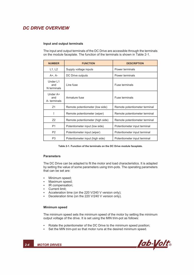
Input and output terminals
The input and output terminals of the DC Drive are accessible through the terminalson the module faceplate. The function of the terminals is shown in Table 2-1.
NUMBER FUNCTION DESCRIPTION
L1, L2 Supply voltage inputs Power terminals
A+, A- DC Drive outputs Power terminals
Under L1and
N terminalsLine fuse Fuse terminals
Under A+and
A- terminalsArmature fuse Fuse terminals
Z1 Remote potentiometer (low side) Remote potentiometer terminal
Remote potentiometer (wiper) Remote potentiometer terminal
Z2 Remote potentiometer (high side) Remote potentiometer terminal
P1 Potentiometer input (low side) Potentiometer input terminal
P2 Potentiometer input (wiper) Potentiometer input terminal
P3 Potentiometer input (high side) Potentiometer input terminal
Table 2-1. Function of the terminals on the DC Drive module faceplate.
Parameters
The DC Drive can be adapted to fit the motor and load characteristics. It is adaptedby setting the value of some parameters using trim-pots. The operating parametersthat can be set are:
Minimum speed;Maximum speed;IR compensation; Current limit;Acceleration time (on the 220 V/240 V version only);Deceleration time (on the 220 V/240 V version only).
Minimum speed
The minimum speed sets the minimum speed of the motor by setting the minimumoutput voltage of the drive. It is set using the MIN trim-pot as follows:
Rotate the potentiometer of the DC Drive to the minimum speed position;Set the MIN trim-pot so that motor runs at the desired minimum speed.

DC DRIVE OVERVIEW
MOTOR DRIVES 2-5
Maximum speed
The maximum speed sets the maximum speed of the motor by setting the maximumoutput voltage of the drive. The maximum speed value is determined to fit the loadrequirements, or to prevent the motor from rotating at a speed exceeding the ratedvalue. It is set using the MAX trim-pot as follows:
Rotate the potentiometer to the maximum speed position;Set the MAX trim-pot so that motor runs at the desired maximum speed.
The IR compensation and Current limit parameters are explained in the nextexercise.
Procedure Summary
In the first two parts of this exercise, you will set the MIN and MAX trim-pots tospecific speed values.
In the third part, you will plot the speed versus voltage curve.
In the fourth part, you will demonstrate the effects of inverting the shunt windings ofa DC motor.
EQUIPMENT REQUIRED
Refer to the Equipment Utilization Chart in Appendix A to obtain the list of equipmentrequired for this exercise.
PROCEDURE
The AC Power Supply provides high voltages. Do not change any
AC connection with the power on.

DC DRIVE OVERVIEW
2-6 MOTOR DRIVES
Basic setup
G 1. Set up the circuit shown in Figure 2-3.
Figure 2-3. Circuit using a DC Drive to control the operation of a DC Motor.
The DC Drive module requires single phase supply. Make sure to connect
the DC Drive between a line terminal and the N terminal on the AC Power
Supply.
G 2. Set the MIN, MAX, IR, and CL trim-pots to the 12 o'clock position.
Note: Be careful when setting the trim-pots, they are fragile.Always use the plastic screwdriver supplied with your trainingsystem.
DC DRIVE OVERVIEW
MOTOR DRIVES 2-7
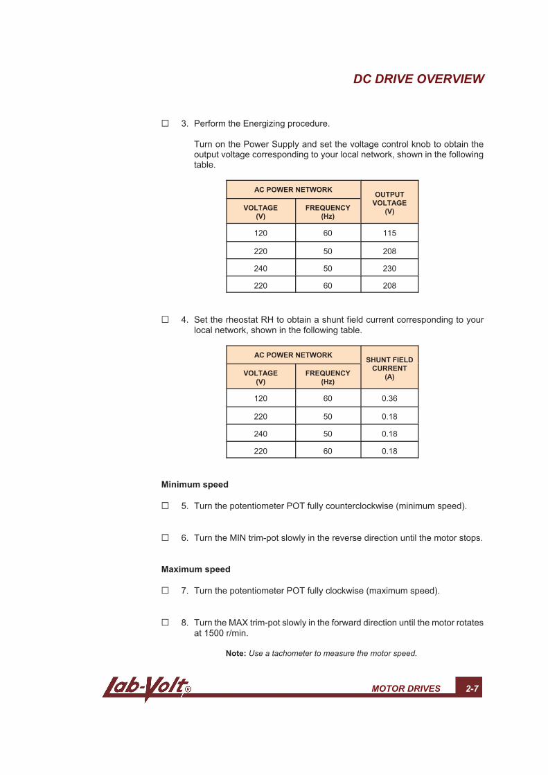
G 3. Perform the Energizing procedure.
Turn on the Power Supply and set the voltage control knob to obtain theoutput voltage corresponding to your local network, shown in the followingtable.
AC POWER NETWORKOUTPUT
VOLTAGE
(V)VOLTAGE
(V)
FREQUENCY
(Hz)
120 60 115
220 50 208
240 50 230
220 60 208
G 4. Set the rheostat RH to obtain a shunt field current corresponding to yourlocal network, shown in the following table.
AC POWER NETWORKSHUNT FIELD
CURRENT
(A)VOLTAGE
(V)
FREQUENCY
(Hz)
120 60 0.36
220 50 0.18
240 50 0.18
220 60 0.18
Minimum speed
G 5. Turn the potentiometer POT fully counterclockwise (minimum speed).
G 6. Turn the MIN trim-pot slowly in the reverse direction until the motor stops.
Maximum speed
G 7. Turn the potentiometer POT fully clockwise (maximum speed).
G 8. Turn the MAX trim-pot slowly in the forward direction until the motor rotatesat 1500 r/min.
Note: Use a tachometer to measure the motor speed.
DC DRIVE OVERVIEW
2-8 MOTOR DRIVES
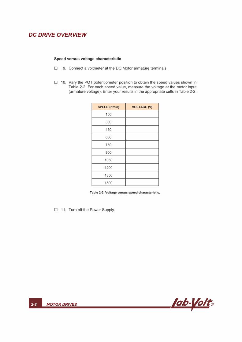
Speed versus voltage characteristic
G 9. Connect a voltmeter at the DC Motor armature terminals.
G 10. Vary the POT potentiometer position to obtain the speed values shown inTable 2-2. For each speed value, measure the voltage at the motor input(armature voltage). Enter your results in the appropriate cells in Table 2-2.
SPEED (r/min) VOLTAGE (V)
150
300
450
600
750
900
1050
1200
1350
1500
Table 2-2. Voltage versus speed characteristic.
G 11. Turn off the Power Supply.

DC DRIVE OVERVIEW
MOTOR DRIVES 2-9
G 12. Plot the Speed versus Voltage curve in Figure 2-4. Place the Voltage valuesalong the X-axis, and the Speed values along the Y-axis.
Figure 2-4. Voltage versus Speed curve.
G 13. Does your graph confirm that the speed of the motor is directly proportionalto the armature voltage?
G Yes G No
Additional speed settings
G 14. In the previous steps, you set the minimum speed to zero, and themaximum speed to 1500 r/min. Familiarize yourself with these controls bysetting the following speed range: 200 to 1400 r/min.
Direction of rotation
G 15. In which direction does the motor rotate?
G Forward G Reverse
G 16. Invert the connections at the armature terminals.
Does the rotation direction change?
G Yes G No

DC DRIVE OVERVIEW
2-10 MOTOR DRIVES
G 17. Determine another method to change the rotation direction of a DC motor.
G 18. Test the method that you determined in the previous step.
G 19. Turn off the Power Supply, disconnect the circuit, and return the equipmentto the storage location.
CONCLUSION
In this exercise, you familiarized yourself with the basic operation of the DC Drive.You set the minimum and maximum speeds of the motor. You plotted the speedversus voltage characteristic and observed that the speed is proportional to thearmature voltage. You change the rotation direction of the motor by modifying thecircuit connections.
REVIEW QUESTIONS
1. Name the parameters that can be set on the DC Drive of your training system.
a. Minimum and maximum speeds, IR compensation, and current limit.b. Operating speed, minimum and maximum current, IR compensation.c. Operating current, minimum, and maximum speeds, IR compensation.d. Minimum and maximum speeds, IR limit, and current compensation.
2. The DC Drive of your training system is capable of controlling
a. the motor speed in both directions.b. the torque in both directions.c. the motor speed in one direction.d. the motor speed and the torque in both directions.
3. The speed of the motor is directly proportional to the armature current.
G True G False