Embed Size (px)
Citation preview
Description
Mounting and
installation
For motor controller
CMMP-AS-...-M0
8049674
1511c
CMMP-AS-...-M0
Motor controller
CMMP-AS-...-M0
2 Festo – GDCP-CMMP-M0-HW-EN – 1511c –
Translation of the original instructions
GDCP-CMMP-M0-HW-EN
CANopen®, Modbus®, Heidenhain®, EnDat®, PHOENIX®, Windows® are registered trademarks of the
respective trademark owners in certain countries.
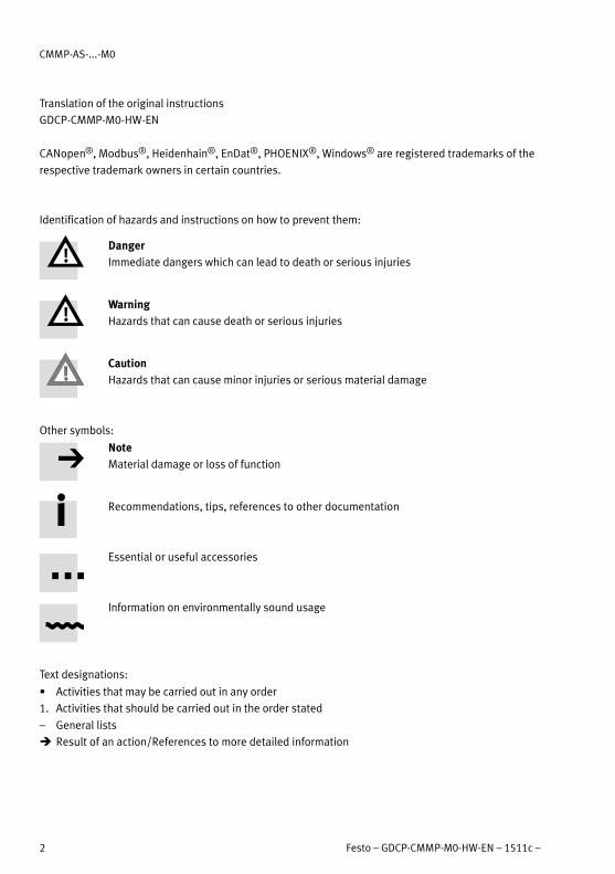
Identification of hazards and instructions on how to prevent them:
Danger
Immediate dangers which can lead to death or serious injuries
Warning
Hazards that can cause death or serious injuries
Caution
Hazards that can cause minor injuries or serious material damage
Other symbols:
Note
Material damage or loss of function
Recommendations, tips, references to other documentation
Essential or useful accessories
Information on environmentally sound usage
Text designations:
� Activities that may be carried out in any order
1. Activities that should be carried out in the order stated
– General lists
� Result of an action/References to more detailed information

CMMP-AS-...-M0
Festo – GDCP-CMMP-M0-HW-EN – 1511c – English 3
Table of Contents – CMMP-AS-...-M0
Instructions on this documentation 6. . . . . . . . . . . . . . . . . . . . . . . . . . . . . . . . . . . . . . . . . . . . . . . . .
Target group 6. . . . . . . . . . . . . . . . . . . . . . . . . . . . . . . . . . . . . . . . . . . . . . . . . . . . . . . . . . . . . . . . . . .
Product identification, versions 6. . . . . . . . . . . . . . . . . . . . . . . . . . . . . . . . . . . . . . . . . . . . . . . . . . . .
Service 6. . . . . . . . . . . . . . . . . . . . . . . . . . . . . . . . . . . . . . . . . . . . . . . . . . . . . . . . . . . . . . . . . . . . . . .
Specified standards/directives 6. . . . . . . . . . . . . . . . . . . . . . . . . . . . . . . . . . . . . . . . . . . . . . . . . . . .
Documentation 8. . . . . . . . . . . . . . . . . . . . . . . . . . . . . . . . . . . . . . . . . . . . . . . . . . . . . . . . . . . . . . . .
1 Safety and requirements for product use 9. . . . . . . . . . . . . . . . . . . . . . . . . . . . . . . . . . . . . .
1.1 Safety 9. . . . . . . . . . . . . . . . . . . . . . . . . . . . . . . . . . . . . . . . . . . . . . . . . . . . . . . . . . . . . . . . . .
1.1.1 Safety instructions for commissioning, repair and de-commissioning 9. . . . . . . .
1.1.2 Protection against electric shock through protective extra-low voltage (PELV) 10.
1.1.3 Intended use 10. . . . . . . . . . . . . . . . . . . . . . . . . . . . . . . . . . . . . . . . . . . . . . . . . . . . .
1.2 Requirements for product use 11. . . . . . . . . . . . . . . . . . . . . . . . . . . . . . . . . . . . . . . . . . . . . . .
1.2.1 Transport and storage conditions 11. . . . . . . . . . . . . . . . . . . . . . . . . . . . . . . . . . . .
1.2.2 Technical requirements 11. . . . . . . . . . . . . . . . . . . . . . . . . . . . . . . . . . . . . . . . . . . .
1.2.3 Qualification of the specialists (requirements for the personnel) 11. . . . . . . . . . . .
1.2.4 Range of application and certifications 11. . . . . . . . . . . . . . . . . . . . . . . . . . . . . . . .
2 Product overview 13. . . . . . . . . . . . . . . . . . . . . . . . . . . . . . . . . . . . . . . . . . . . . . . . . . . . . . . . .
2.1 The entire system for the CMMP-AS-...-M0 13. . . . . . . . . . . . . . . . . . . . . . . . . . . . . . . . . . . . .
2.2 Scope of delivery 14. . . . . . . . . . . . . . . . . . . . . . . . . . . . . . . . . . . . . . . . . . . . . . . . . . . . . . . . . .
2.3 Device view 15. . . . . . . . . . . . . . . . . . . . . . . . . . . . . . . . . . . . . . . . . . . . . . . . . . . . . . . . . . . . . .
3 Mechanical installation 19. . . . . . . . . . . . . . . . . . . . . . . . . . . . . . . . . . . . . . . . . . . . . . . . . . . .
3.1 Important notes 19. . . . . . . . . . . . . . . . . . . . . . . . . . . . . . . . . . . . . . . . . . . . . . . . . . . . . . . . . .
3.2 Mounting 20. . . . . . . . . . . . . . . . . . . . . . . . . . . . . . . . . . . . . . . . . . . . . . . . . . . . . . . . . . . . . . . .
3.2.1 Motor controller 20. . . . . . . . . . . . . . . . . . . . . . . . . . . . . . . . . . . . . . . . . . . . . . . . . .
4 Electrical installation 23. . . . . . . . . . . . . . . . . . . . . . . . . . . . . . . . . . . . . . . . . . . . . . . . . . . . . .
4.1 Safety instructions 23. . . . . . . . . . . . . . . . . . . . . . . . . . . . . . . . . . . . . . . . . . . . . . . . . . . . . . . .
4.2 Allocation of the plug connectors 25. . . . . . . . . . . . . . . . . . . . . . . . . . . . . . . . . . . . . . . . . . . . .
4.3 Connection: I/O communication [X1] 29. . . . . . . . . . . . . . . . . . . . . . . . . . . . . . . . . . . . . . . . . .
4.3.1 Plug [X1]: 29. . . . . . . . . . . . . . . . . . . . . . . . . . . . . . . . . . . . . . . . . . . . . . . . . . . . . . .
4.3.2 Pin assignment [X1] 29. . . . . . . . . . . . . . . . . . . . . . . . . . . . . . . . . . . . . . . . . . . . . . .
4.3.3 Use analogue inputs as digital inputs 30. . . . . . . . . . . . . . . . . . . . . . . . . . . . . . . . .
4.4 Connection: Resolver [X2A] 32. . . . . . . . . . . . . . . . . . . . . . . . . . . . . . . . . . . . . . . . . . . . . . . . . .
4.4.1 Plug [X2A] 32. . . . . . . . . . . . . . . . . . . . . . . . . . . . . . . . . . . . . . . . . . . . . . . . . . . . . . .
4.4.2 Pin assignment [X2A] 32. . . . . . . . . . . . . . . . . . . . . . . . . . . . . . . . . . . . . . . . . . . . . .
4.5 Connection: Encoder [X2B] 33. . . . . . . . . . . . . . . . . . . . . . . . . . . . . . . . . . . . . . . . . . . . . . . . . .
4.5.1 Plug [X2B] 33. . . . . . . . . . . . . . . . . . . . . . . . . . . . . . . . . . . . . . . . . . . . . . . . . . . . . . .

CMMP-AS-...-M0
4 Festo – GDCP-CMMP-M0-HW-EN – 1511c – English
4.5.2 Pin assignment [X2B] 33. . . . . . . . . . . . . . . . . . . . . . . . . . . . . . . . . . . . . . . . . . . . . .
4.6 Connection: CAN bus [X4] 36. . . . . . . . . . . . . . . . . . . . . . . . . . . . . . . . . . . . . . . . . . . . . . . . . . .
4.6.1 Plug [X4] 36. . . . . . . . . . . . . . . . . . . . . . . . . . . . . . . . . . . . . . . . . . . . . . . . . . . . . . . .
4.6.2 Pin assignment [X4] 36. . . . . . . . . . . . . . . . . . . . . . . . . . . . . . . . . . . . . . . . . . . . . . .
4.7 Connection: Motor [X6] 37. . . . . . . . . . . . . . . . . . . . . . . . . . . . . . . . . . . . . . . . . . . . . . . . . . . . .
4.7.1 Plug [X6] 37. . . . . . . . . . . . . . . . . . . . . . . . . . . . . . . . . . . . . . . . . . . . . . . . . . . . . . . .
4.7.2 Pin assignment [X6] 37. . . . . . . . . . . . . . . . . . . . . . . . . . . . . . . . . . . . . . . . . . . . . . .
4.8 Connection: Voltage supply [X9] 39. . . . . . . . . . . . . . . . . . . . . . . . . . . . . . . . . . . . . . . . . . . . . .
4.8.1 Plug 39. . . . . . . . . . . . . . . . . . . . . . . . . . . . . . . . . . . . . . . . . . . . . . . . . . . . . . . . . . . .
4.8.2 Pin assignment [X9] – single-phase 39. . . . . . . . . . . . . . . . . . . . . . . . . . . . . . . . . . .
4.8.3 Pin assignment [X9] – triple-phase 40. . . . . . . . . . . . . . . . . . . . . . . . . . . . . . . . . . . .
4.8.4 Mains fuse 41. . . . . . . . . . . . . . . . . . . . . . . . . . . . . . . . . . . . . . . . . . . . . . . . . . . . . .
4.8.5 AC supply 41. . . . . . . . . . . . . . . . . . . . . . . . . . . . . . . . . . . . . . . . . . . . . . . . . . . . . . .
4.8.6 Braking resistor 43. . . . . . . . . . . . . . . . . . . . . . . . . . . . . . . . . . . . . . . . . . . . . . . . . .
4.9 Connection: Incremental encoder input [X10] 44. . . . . . . . . . . . . . . . . . . . . . . . . . . . . . . . . . .
4.9.1 Plug [X10] 44. . . . . . . . . . . . . . . . . . . . . . . . . . . . . . . . . . . . . . . . . . . . . . . . . . . . . . .
4.9.2 Pin assignment [X10] 44. . . . . . . . . . . . . . . . . . . . . . . . . . . . . . . . . . . . . . . . . . . . . .
4.9.3 Type and design of the cable [X10] 45. . . . . . . . . . . . . . . . . . . . . . . . . . . . . . . . . . .
4.9.4 Connection instructions [X10] 45. . . . . . . . . . . . . . . . . . . . . . . . . . . . . . . . . . . . . . .
4.10 Connection: Incremental encoder output [X11] 45. . . . . . . . . . . . . . . . . . . . . . . . . . . . . . . . . .
4.10.1 Plug [X11] 45. . . . . . . . . . . . . . . . . . . . . . . . . . . . . . . . . . . . . . . . . . . . . . . . . . . . . . .
4.10.2 Pin assignment [X11] 45. . . . . . . . . . . . . . . . . . . . . . . . . . . . . . . . . . . . . . . . . . . . . .
4.11 FCT interfaces 46. . . . . . . . . . . . . . . . . . . . . . . . . . . . . . . . . . . . . . . . . . . . . . . . . . . . . . . . . . . .
4.11.1 Overview of interfaces 46. . . . . . . . . . . . . . . . . . . . . . . . . . . . . . . . . . . . . . . . . . . . .
4.11.2 USB [X19] 46. . . . . . . . . . . . . . . . . . . . . . . . . . . . . . . . . . . . . . . . . . . . . . . . . . . . . . .
4.11.3 Ethernet TCP/IP [X18] 47. . . . . . . . . . . . . . . . . . . . . . . . . . . . . . . . . . . . . . . . . . . . . .
4.12 Connection: I/O interface for STO [X40] 49. . . . . . . . . . . . . . . . . . . . . . . . . . . . . . . . . . . . . . . .
4.12.1 Plug [X40] 49. . . . . . . . . . . . . . . . . . . . . . . . . . . . . . . . . . . . . . . . . . . . . . . . . . . . . . .
4.12.2 Pin assignment [X40] 49. . . . . . . . . . . . . . . . . . . . . . . . . . . . . . . . . . . . . . . . . . . . . .
4.12.3 Circuitry with use of the STO safety function [X40] 49. . . . . . . . . . . . . . . . . . . . . . .
4.12.4 Circuitry without use of the STO safety function [X40] 49. . . . . . . . . . . . . . . . . . . .
4.13 Instructions on safe and EMC-compliant installation 51. . . . . . . . . . . . . . . . . . . . . . . . . . . . . .
4.13.1 Explanations and terms 51. . . . . . . . . . . . . . . . . . . . . . . . . . . . . . . . . . . . . . . . . . . .
4.13.2 General remarks on EMC 51. . . . . . . . . . . . . . . . . . . . . . . . . . . . . . . . . . . . . . . . . . .
4.13.3 EMC areas: First and second environment 52. . . . . . . . . . . . . . . . . . . . . . . . . . . . . .
4.13.4 EMC-compliant wiring 53. . . . . . . . . . . . . . . . . . . . . . . . . . . . . . . . . . . . . . . . . . . . .
4.13.5 Operation with long motor cables 55. . . . . . . . . . . . . . . . . . . . . . . . . . . . . . . . . . . .
4.13.6 ESD protection 55. . . . . . . . . . . . . . . . . . . . . . . . . . . . . . . . . . . . . . . . . . . . . . . . . . .
5 Commissioning 56. . . . . . . . . . . . . . . . . . . . . . . . . . . . . . . . . . . . . . . . . . . . . . . . . . . . . . . . . . .
5.1 General connection instructions 56. . . . . . . . . . . . . . . . . . . . . . . . . . . . . . . . . . . . . . . . . . . . . .
5.2 Tools / material 56. . . . . . . . . . . . . . . . . . . . . . . . . . . . . . . . . . . . . . . . . . . . . . . . . . . . . . . . . . .
5.3 Connecting the motor 56. . . . . . . . . . . . . . . . . . . . . . . . . . . . . . . . . . . . . . . . . . . . . . . . . . . . . .

CMMP-AS-...-M0
Festo – GDCP-CMMP-M0-HW-EN – 1511c – English 5
5.4 Connect motor controller CMMP-AS-...-M0 to the power supply 57. . . . . . . . . . . . . . . . . . . . .
5.5 Connecting a PC 57. . . . . . . . . . . . . . . . . . . . . . . . . . . . . . . . . . . . . . . . . . . . . . . . . . . . . . . . . .
5.6 Check operating status 58. . . . . . . . . . . . . . . . . . . . . . . . . . . . . . . . . . . . . . . . . . . . . . . . . . . . .
6 Service functions and diagnostic messages 59. . . . . . . . . . . . . . . . . . . . . . . . . . . . . . . . . . . .
6.1 Protective and service functions 59. . . . . . . . . . . . . . . . . . . . . . . . . . . . . . . . . . . . . . . . . . . . . .
6.1.1 Overview 59. . . . . . . . . . . . . . . . . . . . . . . . . . . . . . . . . . . . . . . . . . . . . . . . . . . . . . . .
6.1.2 Phases and mains failure detection 59. . . . . . . . . . . . . . . . . . . . . . . . . . . . . . . . . . .
6.1.3 Overload current and short-circuit monitoring 59. . . . . . . . . . . . . . . . . . . . . . . . . .
6.1.4 Overvoltage monitoring for the intermediate circuit 59. . . . . . . . . . . . . . . . . . . . . .
6.1.5 Temperature monitoring for the heat sink 59. . . . . . . . . . . . . . . . . . . . . . . . . . . . . .
6.1.6 Monitoring of the motor 60. . . . . . . . . . . . . . . . . . . . . . . . . . . . . . . . . . . . . . . . . . . .
6.1.7 I2t monitoring 60. . . . . . . . . . . . . . . . . . . . . . . . . . . . . . . . . . . . . . . . . . . . . . . . . . . .
6.1.8 Power monitoring for the brake chopper 60. . . . . . . . . . . . . . . . . . . . . . . . . . . . . . .
6.1.9 Commissioning status 61. . . . . . . . . . . . . . . . . . . . . . . . . . . . . . . . . . . . . . . . . . . . .
6.1.10 Rapid discharge of the intermediate circuit 61. . . . . . . . . . . . . . . . . . . . . . . . . . . . .
6.1.11 Detection of faults in conjunction with the functional safety engineering 61. . . . .
6.2 Operating mode and diagnostic messages 61. . . . . . . . . . . . . . . . . . . . . . . . . . . . . . . . . . . . .
6.2.1 Operation and display components 61. . . . . . . . . . . . . . . . . . . . . . . . . . . . . . . . . . .
6.2.2 7-segment display 62. . . . . . . . . . . . . . . . . . . . . . . . . . . . . . . . . . . . . . . . . . . . . . . .
6.2.3 Acknowledgement of error messages 63. . . . . . . . . . . . . . . . . . . . . . . . . . . . . . . . .
6.2.4 Diagnostic messages 63. . . . . . . . . . . . . . . . . . . . . . . . . . . . . . . . . . . . . . . . . . . . . .
7 Maintenance, care, repair and replacement 64. . . . . . . . . . . . . . . . . . . . . . . . . . . . . . . . . . . .
7.1 Maintenance and care 64. . . . . . . . . . . . . . . . . . . . . . . . . . . . . . . . . . . . . . . . . . . . . . . . . . . . . .
7.2 Repair 64. . . . . . . . . . . . . . . . . . . . . . . . . . . . . . . . . . . . . . . . . . . . . . . . . . . . . . . . . . . . . . . . . .
7.3 Replacement and disposal 64. . . . . . . . . . . . . . . . . . . . . . . . . . . . . . . . . . . . . . . . . . . . . . . . . .
7.3.1 Dismounting and installation 64. . . . . . . . . . . . . . . . . . . . . . . . . . . . . . . . . . . . . . . .
7.3.2 Disposal 64. . . . . . . . . . . . . . . . . . . . . . . . . . . . . . . . . . . . . . . . . . . . . . . . . . . . . . . .
A Technical appendix 65. . . . . . . . . . . . . . . . . . . . . . . . . . . . . . . . . . . . . . . . . . . . . . . . . . . . . . . .
A.1 Technical data CMMP-AS-...-M0 65. . . . . . . . . . . . . . . . . . . . . . . . . . . . . . . . . . . . . . . . . . . . . .
A.1.1 Interfaces 73. . . . . . . . . . . . . . . . . . . . . . . . . . . . . . . . . . . . . . . . . . . . . . . . . . . . . . .
A.2 Supported encoders 79. . . . . . . . . . . . . . . . . . . . . . . . . . . . . . . . . . . . . . . . . . . . . . . . . . . . . . .
B Diagnostic messages 81. . . . . . . . . . . . . . . . . . . . . . . . . . . . . . . . . . . . . . . . . . . . . . . . . . . . . .
B.1 Explanations of the diagnostic messages 81. . . . . . . . . . . . . . . . . . . . . . . . . . . . . . . . . . . . . .
B.2 Diagnostic messages with instructions for fault clearance 82. . . . . . . . . . . . . . . . . . . . . . . . .
Index 121. . . . . . . . . . . . . . . . . . . . . . . . . . . . . . . . . . . . . . . . . . . . . . . . . . . . . . . . . . . . . . . . . . . . . . . .
CMMP-AS-...-M0
6 Festo – GDCP-CMMP-M0-HW-EN – 1511c – English
Instructions on this documentation
This documentation is intended to help you safely work with the motor controller CMMP-AS-...-M0 and
describes the mounting and installation processes.
Target group
This documentation is intended exclusively for technicians trained in control and automation techno
logy, who have experience in installation, commissioning, programming and diagnostics of positioning
systems.
Product identification, versions
This description refers to the following versions:
– CMMP-AS-...-M0 from Rev 01
– FCT plug-in CMMP-AS from Version 2.3.x.
Note
Before using a newer firmware version, check whether a newer version of the FCT plug-
in or user documentation is available for it
Support Portal: � www.festo.com/sp
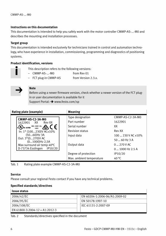
Rating plate (example) Meaning
In: 1* (100...230)V AC±10% (50...60)Hz 3AOut: 3*(0...270)V AC (0...1000)Hz 2,5AMax surround air temp 40°CD-73734 Esslingen IP10/20
CMMP-AS-C2-3A-M01622901 XX Rev XX
IND. CONT. EQ.
1UD1
Type designation CMMP-AS-C2-3A-M0
Part number 1622901
Serial number XX
Revision status Rev XX
Input data 100 … 230 V AC ±10%
50 … 60 Hz 3 A
Output data
Degree of protection
0 … 270 V AC
0 … 1000 Hz 2.5 A
IP10/20
Max. ambient temperature 40 °C
Tab. 1 Rating plate example CMMP-AS-C2-3A-M0
Service
Please consult your regional Festo contact if you have any technical problems.
Specified standards/directives
Issue status
2006/42/EC EN 60204-1:2006-06/A1:2009-02
2006/95/EC EN 50178:1997-10
2004/108/EC IEC 61131-2:2007-09
EN 61800-3:2004-12 + A1:2012-3
Tab. 2 Standards/directives specified in the document
CMMP-AS-...-M0
Festo – GDCP-CMMP-M0-HW-EN – 1511c – English 7
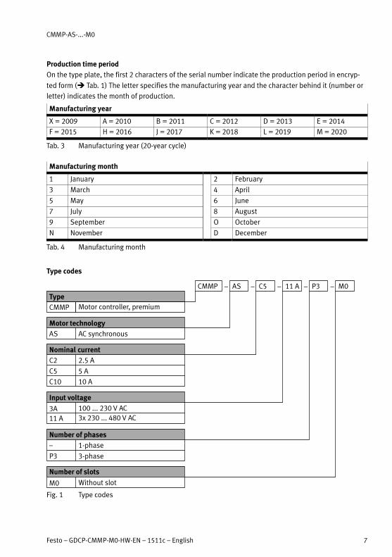
Production time period
On the type plate, the first 2 characters of the serial number indicate the production period in encryp
ted form (� Tab. 1) The letter specifies the manufacturing year and the character behind it (number or
letter) indicates the month of production.
Manufacturing year
X = 2009 A = 2010 B = 2011 C = 2012 D = 2013 E = 2014
F = 2015 H = 2016 J = 2017 K = 2018 L = 2019 M = 2020
Tab. 3 Manufacturing year (20-year cycle)
Manufacturing month
1 January 2 February
3 March 4 April
5 May 6 June
7 July 8 August
9 September O October
N November D December
Tab. 4 Manufacturing month
Type codes
– – – – –CMMP
Type
AS C5 11 A P3
CMMP Motor controller, premium
Motor technology
AS AC synchronous
Nominal current
C2 2.5 A
Input voltage
3A 100 ... 230 V AC
Number of phases
– 1-phase
M0
C5 5 A
C10 10 A
11 A 3x 230 ... 480 V AC
P3 3-phase
M0 Without slot
Number of slots
Fig. 1 Type codes

CMMP-AS-...-M0
8 Festo – GDCP-CMMP-M0-HW-EN – 1511c – English
Documentation
You will find additional information on the motor controller in the following documentation:
User documentation on the motor controller CMMP-AS-...-M0
Name, type Table of contents
Hardware description,
GDCP-CMMP-M0-HW-...
Mounting and installation of the motor controller CMMP-
AS-...-M0 for all variants/output classes (1-phase, 3-phase), pin
assignments, error messages, maintenance.
Function descriptions,
GDCP-CMMP-M0-FW-...
Functional description (firmware) CMMP-AS-...-M0, Instructions
on commissioning.
Description FHPP,
GDCP-CMMP-M3/-M0-C-HP-...
Control and parameterisation of the motor controller via the
FHPP Festo profile.
– Motor controller CMMP-AS-...-M3 with the following field
busses: CANopen, Modbus TCP, PROFINET, PROFIBUS, Ether
Net/IP, DeviceNet, EtherCAT.
– Motor controller CMMP-AS-...-M0 with fieldbus CANopen,
Modbus TCP.
Description CiA 402 (DS 402),
GDCP-CMMP-M3/-M0-C-CO-...
Control and parameterisation of the motor controller via the
device profile CiA 402 (DS 402)
– Motor controller CMMP-AS-...-M3 with the following field
busses: CANopen and EtherCAT.
– Motor controller CMMP-AS-...-M0 with fieldbus CANopen.
Description CAM-Editor,
P.BE-CMMP-CAM-SW-...
Cam disc function (CAM) of the motor controller CMMP-
AS-...-M3/-M0.
Description of the safety function
STO, GDCP-CMMP-AS-M0-S1-...
Functional safety engineering for the motor controller CMMP-
AS-...-M0 with the integrated safety function STO.
Help for the FCT plug-in CMMP-AS User interface and functions of the CMMP-AS plug-in for the
Festo Configuration Tool � www.festo.com/sp.
Tab. 5 Documentation on the motor controller CMMP-AS-...-M0

1 Safety and requirements for product use
Festo – GDCP-CMMP-M0-HW-EN – 1511c – English 9
1 Safety and requirements for product use
1.1 Safety
1.1.1 Safety instructions for commissioning, repair and de-commissioning
Warning
Danger of electric shock.
– When cables are not mounted to the plugs [X6] and [X9].
– When connecting cables are disconnected when powered.
Touching live parts can result in severe injuries and even death.
The product may only be operated in a built-in status and when all protective measures
have been initiated.
Before touching live parts during maintenance, repair and cleaning work and when there
have been long service interruptions:
1. Switch off power to the electrical equipment via the mains switch and secure it
against being switched on again.
2. After switch-off, wait at least 5 minutes discharge time and check that power is
turned off before accessing the controller.
The safety functions do not protect against electric shock but only against dangerous
movements!
Note
Danger from unexpected movement of the motor or axis.
– Make sure that the movement does not endanger anyone.
– Perform a risk assessment in accordance with the EC machinery directive.
– Based on this risk assessment, design the safety system for the entire machine,
taking into account all integrated components. This also includes the electric drives.
– Bypassing safety equipment is impermissible.
1 Safety and requirements for product use
10 Festo – GDCP-CMMP-M0-HW-EN – 1511c – English
1.1.2 Protection against electric shock through protective extra-low voltage (PELV)
Warning
� Use for the electrical power supply only PELV circuits in accordance with EN 60204-1
(Protective Extra-Low Voltage, PELV).
Also take into account the general requirements for PELV circuits in accordance with
EN�60204-1.
� Use only power sources which guarantee reliable electrical isolation of the operating
voltage as per EN 60204-1.
Through the use of PELV circuits, protection from electric shock (protection from direct and indirect
contact) in accordance with EN 60204-1 is ensured (Electrical equipment of machines. General require
ments).
1.1.3 Intended use
The CMMP-AS-...-M0 is intended for ...
– Use in control cabinets for power supply to AC servo motors and their regulation of torques (cur
rent), rotational speed and position.
The CMMP-AS-...-M0 is intended for installation in machines or automated systems and may be used
only as follows:
– in excellent technical condition,
– in original status without unauthorised modifications,
– within the limits of the product defined by the technical data
(� Appendix A Technical appendix),
– in an industrial environment.
The product is intended for use in industrial areas. When used outside an industrial environment, e.g. in
commercial and mixed residential areas, measures for radio interference suppression may be ne
cessary.
Note
In the event of damage caused by unauthorised manipulation or other than intended
use, the guarantee is invalidated and the manufacturer is not liable for damages.
1 Safety and requirements for product use
Festo – GDCP-CMMP-M0-HW-EN – 1511c – English 11
1.2 Requirements for product use
� Make this documentation available to the design engineer, installer and personnel responsible for
commissioning the machine or system in which this product is used.
� Make sure that the specifications of the documentation are always complied with. Also consider the
documentation for the other components and modules.
� Take into consideration the legal regulations applicable for the destination, as well as:
– regulations and standards,
– regulations of the testing organizations and insurers,
– national specifications.
1.2.1 Transport and storage conditions
� Protect the product during transport and storage from impermissible burdens, such as:
– mechanical loads,
– impermissible temperatures,
– moisture,
– aggressive atmospheres.
� Store and transport the product in its original packaging. The original packaging offers sufficient
protection from typical stresses.
1.2.2 Technical requirements
General conditions for the correct and safe use of the product, which must be observed at all times:
� Comply with the connection and environmental conditions of the product (� Appendix A) and all
connected components specified in the technical data.
Only compliance with the limit values or load limits will enable operation of the product in compli
ance with the relevant safety regulations.
� Observe the instructions and warnings in this documentation.
1.2.3 Qualification of the specialists (requirements for the personnel)
The product may only be placed in operation by a qualified electrotechnician who is familiar with:
– the installation and operation of electrical control systems,
– the applicable regulations for operating safety-engineered systems,
– the applicable regulations for accident protection and occupational safety, and
– the documentation for the product.
1.2.4 Range of application and certifications
Standards and test values, which the product complies with and fulfils, can be found in the “Technical
data” section (� Appendix A). The product-relevant EU directives can be found in the declaration of
conformity.
Certificates and declaration of conformity on this product can be found at
� www.festo.com/sp.

1 Safety and requirements for product use
12 Festo – GDCP-CMMP-M0-HW-EN – 1511c – English
The current revisions and special configurations of earlier revisions (order code ...-C1) of the product
have been certified by Underwriters Laboratories Inc. (UL) for the USA and Canada. These are marked
as follows:
UL Listing Mark for Canada and the United States
Note
Observe the following if the UL requirements are to be complied with in your applica
tion:
– Rules for observing the UL certification can be found in the separate UL special
documentation. The technical data stated therein take priority.
– The technical data in this documentation may show values deviating from this.
Certain configurations of earlier revisions of the product have been certified by Underwriters Laborator
ies Inc. (UL) for the USA. These are marked as follows:
UL Listing Mark for the United States

2 Product overview
Festo – GDCP-CMMP-M0-HW-EN – 1511c – English 13
2 Product overview
2.1 The entire system for the CMMP-AS-...-M0
A motor controller CMMP-AS-...-M0 entire system is shown in � Fig. 2.1 � Page 14. For operation of
the motor controller, the following components are required:
– Mains power switch
– FI circuit breaker (RCD), all-current sensitive 300 mA
– Automatic circuit breaker
– Power supply 24 V DC
– Motor controller CMMP-AS-...-M0
– Motor with motor and encoder cables
A Windows PC with USB or Ethernet connection is required for parametrisation.
Observe the instructions regarding mains fuses in � Chapter 4.

2 Product overview
14 Festo – GDCP-CMMP-M0-HW-EN – 1511c – English
1
2
3
4
6
5
7
1 Power switch
2 Fuse
3 Power pack for logic voltage
4 Optional: external braking resistor
5 Motor controller CMMP-AS-...-M0
6 PC
7 Motor (e.g. EMMS-AS with encoder)
Fig. 2.1 Complete structure CMMP-AS-...-M0 with motor and PC
2.2 Scope of delivery
The delivery includes:
Scope of delivery
Motor controller CMMP-AS-...-M0
Operator package CD
Brief description
Assortment of plugs NEKM-C-7, NEKM-C-8
Tab. 2.1 Scope of delivery

2 Product overview
Festo – GDCP-CMMP-M0-HW-EN – 1511c – English 15
2.3 Device view
1
4
5
6
7
8
9
aJ
2
3
1 Digital I/O interface for control of the STO
function [X40]
2 Activation of firmware download [S3]
3 SD-/MMC card slot [M1]
4 Activation of CANopen terminating resistor
[S2]
5 CANopen interface [X4]
6 Ethernet interface [X18]
7 USB interface [X19]
8 7-segment display
9 Reset button
aJ LEDs
Fig. 2.2 Motor controller CMMP-AS-...-M0: Front view

2 Product overview
16 Festo – GDCP-CMMP-M0-HW-EN – 1511c – English
4
5
3
2
1
1 PE connection
2 I/O communication [X1]
3 Incremental encoder input [X10]
4 Incremental encoder output [X11]
5 Power supply [X9]
Fig. 2.3 Motor controller CMMP-AS-...-3A-M0: Top view
2 Product overview
Festo – GDCP-CMMP-M0-HW-EN – 1511c – English 17
4
3
2
1
5
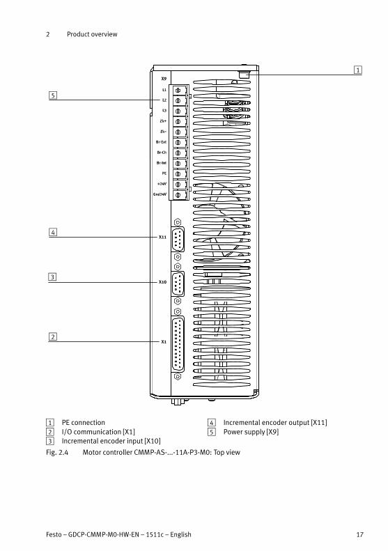
1 PE connection
2 I/O communication [X1]
3 Incremental encoder input [X10]
4 Incremental encoder output [X11]
5 Power supply [X9]
Fig. 2.4 Motor controller CMMP-AS-...-11A-P3-M0: Top view

2 Product overview
18 Festo – GDCP-CMMP-M0-HW-EN – 1511c – English
1
2
3
4
1 Spring-loaded terminal connection for the
outer shield of the motor cable
2 Motor connection [X6]
3 Connection for the resolver [X2A]
4 Connection for the encoder [X2B]
Fig. 2.5 Motor controller CMMP-AS-...-M0: Bottom view

3 Mechanical installation
Festo – GDCP-CMMP-M0-HW-EN – 1511c – English 19
3 Mechanical installation
3.1 Important notes
Note
Proceed carefully when mounting. During mounting and subsequent operation of the
drive, ensure that that no metal shavings, metal dust or mounting parts (screws, nuts,
pieces of wire) fall into the motor controller.
Note
The motor controllers CMMP-AS-...-M0
� Use only as installed devices for control cabinet mounting.
� Mounting orientation with the power supply [X9] on top.
� Mount it with the clip on the mounting plate.
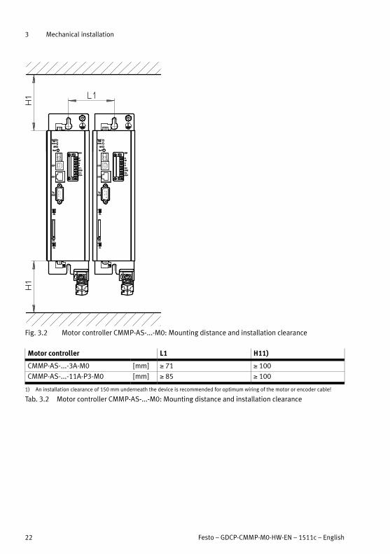
� Installation clearances:
For sufficient ventilation of the device, a minimum clearance of 100 mm to other
sub-assemblies is required above and below the device.
� An installation clearance of 150 mm underneath the device is recommended for
optimum wiring of the motor or encoder cable!
� The motor controllers of the CMMP-AS-...-M0 family are designed in such a way that
they can be mounted directly on a heat-dissipating mounting plate if used as inten
ded and installed correctly. We wish to point out that excessive heating can lead to
premature aging and/or damage to the device. With high thermal stress on the mo
tor controller CMMP-AS-...-M0, a mounting distance (� Fig. 3.2) is recommended!

3 Mechanical installation
20 Festo – GDCP-CMMP-M0-HW-EN – 1511c – English
3.2 Mounting
Observe the safety instructions � Chapter 1 during mounting and installation work.
Please note
Damage to the motor controller due to incorrect handling.
� Switch off the supply voltage before mounting and installation work. Switch on sup
ply voltage only when mounting and installation work are completely finished.
� Observe the handling specifications for electrostatically sensitive devices. Do not touch
the printed circuit board and the pins of the manifold rail in the motor controller.
3.2.1 Motor controller
Mounting clips are located at the top and bottom of the motor controller CMMP-AS-...-M0. They are
used to attach the motor controller vertically to a mounting plate. The clips are part of the radiator
profile, ensuring an optimal heat transfer to the mounting plate.
Please use size M5 screws to attach the motor controller CMMP-AS-...-M0.
3 Mechanical installation
Festo – GDCP-CMMP-M0-HW-EN – 1511c – English 21
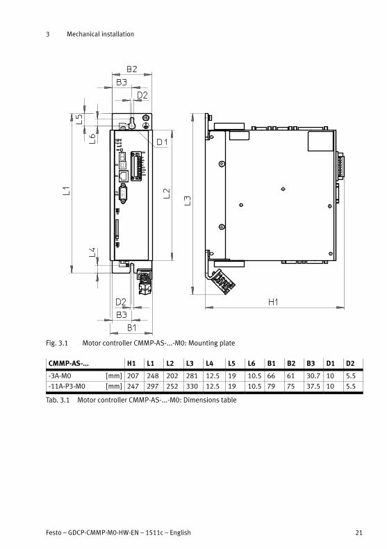
Fig. 3.1 Motor controller CMMP-AS-...-M0: Mounting plate
CMMP-AS-... H1 L1 L2 L3 L4 L5 L6 B1 B2 B3 D1 D2
-3A-M0 [mm] 207 248 202 281 12.5 19 10.5 66 61 30.7 10 5.5
-11A-P3-M0 [mm] 247 297 252 330 12.5 19 10.5 79 75 37.5 10 5.5
Tab. 3.1 Motor controller CMMP-AS-...-M0: Dimensions table
3 Mechanical installation
22 Festo – GDCP-CMMP-M0-HW-EN – 1511c – English
Fig. 3.2 Motor controller CMMP-AS-...-M0: Mounting distance and installation clearance
Motor controller L1 H11)
CMMP-AS-...-3A-M0 [mm] 71 100
CMMP-AS-...-11A-P3-M0 [mm] 85 100
1) An installation clearance of 150 mm underneath the device is recommended for optimum wiring of the motor or encoder cable!
Tab. 3.2 Motor controller CMMP-AS-...-M0: Mounting distance and installation clearance

4 Electrical installation
Festo – GDCP-CMMP-M0-HW-EN – 1511c – English 23
4 Electrical installation
4.1 Safety instructions
Warning
Danger of electric shock
Motor controllers are devices with increased leakage current ( 3.5 mA). If wiring is
incorrect or the device is defective, high voltage can occur on the housing, which can
result in serious injury or even death if the housing is touched.
� Before commissioning, also for brief measuring and test purposes, connect the PE
protective conductor:
– to the earthing screw of the controller housing
– to pin PE [X9], power supply.
The cross section of the protective conductor at PE [X9] must correspond at least
to the cross section of the external conductor L [X9].
� Observe the regulations of EN 60204-1 for the protective earthing.
Warning
Danger of electric shock
– when the module or cover plate is not mounted on the card slot [EXT]
– when cables are not mounted to the plugs [X6] and [X9]
– if connecting cables are disconnected when powered.
Touching live parts causes severe injuries and can lead to death. Before mounting and
installation work:
1. Switch off power to the electrical equipment via the mains switch and secure it
against being switched on again.
2. After switch-off, wait at least 5 minutes discharge time and check that power is
turned off before accessing the controller.
Warning
Danger of electric shock
This product can cause a DC current in the protective ground conductor. In cases where
an error current protection unit (RCD) or an error current monitoring device (RCM) is
used to protect against direct or indirect contact, only the Type B kind of RCD or RCM is
permitted on the power supply side of this product.

4 Electrical installation
24 Festo – GDCP-CMMP-M0-HW-EN – 1511c – English
Caution
Danger from unexpected movement
Faulty pre-assembled lines may destroy the electronics and trigger unexpected move
ments of the motor.
� When wiring the system, use only the supplied plug connectors and preferably the
cables listed in the catalogue as accessories.
� www.festo.com/catalogue
� Lay all flexible lines so that they are free of kinks and free of mechanical stress; if
necessary use chain link trunking.
Note
ESD (electrostatic discharge) can cause damage to the device or other system parts at
plug connectors that are not used.
� Before installation: Earth the system parts and use appropriate ESD equipment (e.g.
shoes, earthing straps etc.).
� After installation: Seal unassigned Sub-D plug connectors with protective caps
(available at authorized dealers).
� Observe the handling specifications for electrostatically sensitive devices.
4 Electrical installation
Festo – GDCP-CMMP-M0-HW-EN – 1511c – English 25
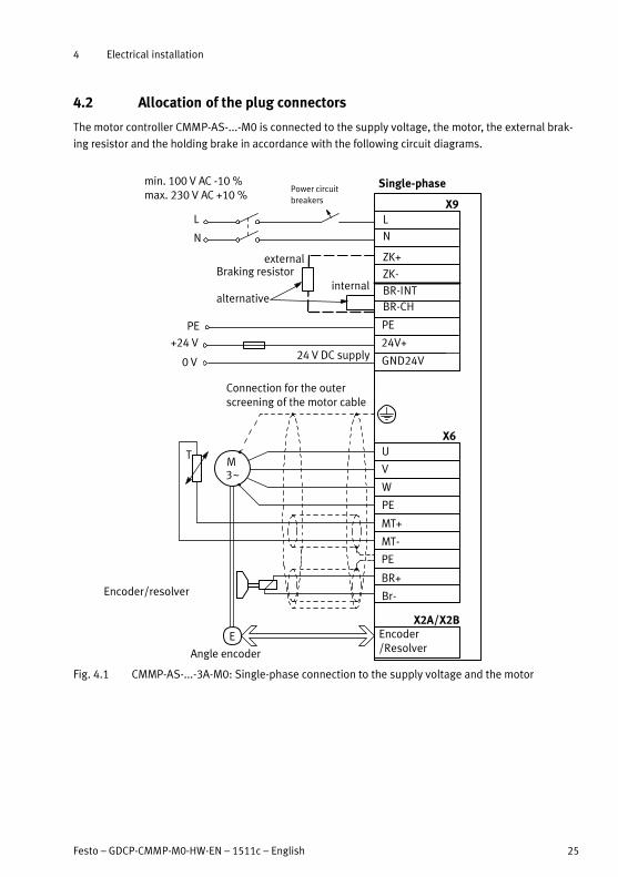
4.2 Allocation of the plug connectors
The motor controller CMMP-AS-...-M0 is connected to the supply voltage, the motor, the external brak
ing resistor and the holding brake in accordance with the following circuit diagrams.
0 V
externalBraking resistor
alternative
Encoder/resolver
Angle encoder
PE
BR-CH
BR-INT
ZK+
ZK-
L
N
24V+
GND24V
U
V
W
PE
MT+
MT-
PE
BR+
Br-
E
M3~
T
X9
X6
X2A/X2B
Single-phasemin. 100 V AC -10 %max. 230 V AC +10 %
internal
PE
+24 V
Encoder/Resolver
24 V DC supply
Connection for the outerscreening of the motor cable
L
N
Power circuit
breakers
Fig. 4.1 CMMP-AS-...-3A-M0: Single-phase connection to the supply voltage and the motor
4 Electrical installation
26 Festo – GDCP-CMMP-M0-HW-EN – 1511c – English
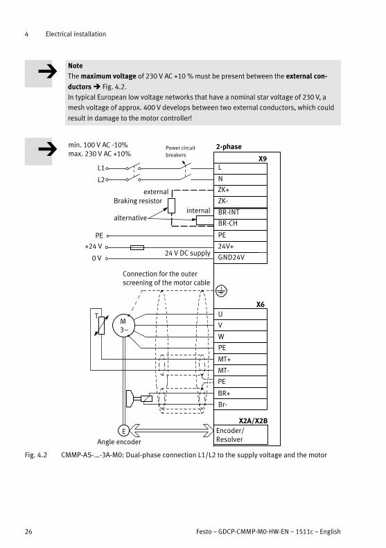
Note
The maximum voltage of 230 V AC +10 % must be present between the external con
ductors � Fig. 4.2.
In typical European low voltage networks that have a nominal star voltage of 230 V, a
mesh voltage of approx. 400 V develops between two external conductors, which could
result in damage to the motor controller!
0 V
external
Braking resistor
alternative
Angle encoder
PE
BR-CH
BR-INT
ZK+
ZK-
L
N
24V+
GND24V
U
V
W
PE
MT+
MT-
PE
BR+
Br-
E
M3~
T
X9
X6
X2A/X2B
2-phasemin. 100 V AC -10%max. 230 V AC +10%
internal
PE
+24 V
Encoder/Resolver
24 V DC supply
Connection for the outerscreening of the motor cable
L1
L2
Power circuit
breakers
Fig. 4.2 CMMP-AS-...-3A-M0: Dual-phase connection L1/L2 to the supply voltage and the motor

4 Electrical installation
Festo – GDCP-CMMP-M0-HW-EN – 1511c – English 27
+24 V
externalBraking resistor
internal
alternative
Angle encoder
BR-EXT
BR-CH
BR-INT
ZK+
ZK-
L1
L2
L3
PE
24V+
GND24V
PE
U
V
W
PE
MT+
MT-
PE
BR+
Br-
E
M3~
T
0 V
X9
X6
X2A/X2B
3-phase
Encoder/Resolver
min. 230 V AC -10%max. 480 V AC +10%
24 V DC supply
Connection for the outerscreening of the motor cable
L1
L2
L3
Power circuit
breakers
Fig. 4.3 CMMP-AS-...-11A-M0: Triple-phase connection to the supply voltage and the motor

4 Electrical installation
28 Festo – GDCP-CMMP-M0-HW-EN – 1511c – English
The power supply cables for the power end stage are alternatively connected to the following terminals:
Power end stage supply
Observe instructions in chapter � 4.8.5
AC supply L, N for single-phase motor controllers
L1, L2, L3 for three-phase motor controllers
DC supply ZK+, ZK–
Tab. 4.1 Connection of power supply cables
Motor temperature switch
PTC or N/C contact/
N/O contact1)
(e.g. KTY81)
MT+, MT–;
[X6]
if this is carried together with the motor phases in
one cable
Analogue
temperature sensor1)
MT+, MT–;
[X2A] or [X2B]
1) EMMS-AS motors have a PTC
Tab. 4.2 Connection of the motor temperature switch
Note
Temperature sensors must be sufficiently isolated from the motor winding.
The connection of the encoder/resolver via the Sub-D plug connector to [X2A] or [X2B] is roughly shown
diagrammatically in � Fig. 4.1,
� Fig. 4.2 and � Fig. 4.3.
Note
If the polarity of the operating voltage connections is reversed, or if the operating
voltage is too high or the operating voltage and motor connections are reversed, the
motor controller CMMP-AS-...-M0 will be damaged.

4 Electrical installation
Festo – GDCP-CMMP-M0-HW-EN – 1511c – English 29
4.3 Connection: I/O communication [X1]
4.3.1 Plug [X1]:
Motor controller Design on the device Counterplug
CMMP-AS-...-M0 Sub-D plug connector, 25-pin, socket Sub-D plug connector, 25-pin, pins
Tab. 4.3 Plug design [X1]
4.3.2 Pin assignment [X1]
See Technical data � section A.1.1 for connected loads of the inputs and outputs.
In the firmware factory setting (delivery status) the control interface for CANopen is parameterised (bus
settings via DIL switch) to enable a device to be replaced without FCT � Tab. 4.4.
[X1] Pin no. Desig
nation
Specification
13 DOUT3 Output freely parameterisable, optionally parameterisable as DIN11
25 DOUT2 Output freely parameterisable, optionally parameterisable as DIN10
12 DOUT1 Output freely parameterisable
24 DOUT0 Controller ready, output permanently assigned
11 DIN 9 Fieldbus data profile (CiA 402, FHPP), input freely parameterisable
23 DIN 8 Fieldbus activation communication, input freely parameterisable
10 DIN7 Limit switch 1 (blocks n 0), input permanently assigned
22 DIN6 Limit switch 0 (blocks n 0), input permanently assigned
9 DIN5 Controller enable, input permanently assigned
21 DIN4 End stage enable, input permanently assigned
8 DIN 3 Fieldbus offset node number bit 3, input freely parameterisable
20 DIN 2 Fieldbus offset node number bit 2, input freely parameterisable
7 DIN 1 Fieldbus offset node number bit 1, input freely parameterisable
19 DIN 0 Fieldbus offset node number bit 0, input freely parameterisable
6 GND24 Reference potential for digital I/Os
18 +24 V 24 V output
5 AOUT1 Analogue output freely parameterisable
17 AOUT0 Analogue output freely parameterisable
4 +VREF Reference output for setpoint potentiometer
16 DIN13 Fieldbus transmission rate bit 1, optionally parameterisable as AIN21)
3 DIN12 Fieldbus transmission rate bit 0, optionally parameterisable as AIN11)
15 #AIN0 Setpoint input 0, differential analogue input
2 AIN0
14 AGND Reference potential for analogue signals
1 AGND Screening for analogue signals, AGND
1) Configuration with FCT. Observe not � Abschnitt 4.3.3.
Tab. 4.4 Pin assignment: I/O communication [X1] (firmware factory setting)

4 Electrical installation
30 Festo – GDCP-CMMP-M0-HW-EN – 1511c – English
The standard assignment of the I/O interface in the FCT corresponds to � Tab. 4.5.
[X1] Pin no. Desig
nation
Specification
13 DOUT3 Following error, output freely parameterisable, optionally paramet
erisable as DIN11
25 DOUT2 Brake unlocked, output freely parameterisable, optionally paramet
erisable as DIN10
12 DOUT1 Motion Complete, Output freely parameterisable
24 DOUT0 Controller ready, output permanently assigned
11 DIN 9 Flying measurement (sample)/reference switch, input freely para
meterisable
23 DIN 8 Start positioning task, input freely parameterisable
10 DIN7 Limit switch 1 (blocks n 0), input permanently assigned
22 DIN6 Limit switch 0 (blocks n 0), input permanently assigned
9 DIN5 Controller enable, input permanently assigned
21 DIN4 End stage enable, input permanently assigned
8 DIN 3 Position selector bit 3, input freely parameterisable
20 DIN 2 Position selector bit 2, input freely parameterisable
7 DIN 1 Position selector bit 1, input freely parameterisable
19 DIN 0 Position selector bit 0, input freely parameterisable
6 GND24 Reference potential for digital I/Os
18 +24 V 24 V output
5 AOUT1 Position setpoint value, analogue output freely parameterisable
17 AOUT0 Speed setpoint value, analogue output freely parameterisable
4 +VREF Reference output for setpoint potentiometer
16 AIN13 Setpoint input 2, single ended analogue input, optionally paramet
erisable as DIN131)
3 AIN12 Setpoint input 1, single ended analogue input, optionally paramet
erisable as DIN121)
15 #AIN0 Setpoint input 0, differential analogue input
2 AIN0
14 AGND Reference potential for analogue signals
1 AGND Screening for analogue signals, AGND
1) Configuration with FCT. Observe not � Section 4.3.3.
Tab. 4.5 Pin assignment: I/O communication [X1] (FCT factory setting)
4.3.3 Use analogue inputs as digital inputs
If the digital inputs AIN1 and ANI2 are used as digital inputs, then a ground reference from AGND to
GND24 at plug X1 pins 14 and 6 must be established.
Note
Connecting AGND to GND24 renders the electronics overvoltage protection inoperable.

4 Electrical installation
Festo – GDCP-CMMP-M0-HW-EN – 1511c – English 31
Controller CMMP-AS-…-M0
Pin no.
x1
AIN0
#AIN0
AIN1
AIN2
+VREF
AGND
AOUT0
AOUT1
AGND
100 mAmax!
+24 V DC
DIN 0
DIN9
DOUT0
DOUT3
GND24
100 mAmax!
PE PE
GND24
+24 V DC
AGND
AIN0
#AIN0
AIN1/AIN2
AGND
AGND
+VREF
AGND
+15 V DC
AMON0/1
AGND
DINX
AGNDGND
GND24
GND
GND
GND24
+24 V DC
DOUTX
Plug housing
2
15
3
16
4
14
17
5
14
1
18
19
11
24
13
6
Fig. 4.4 Basic circuit diagram of connection [X1]
Control cable and Sub-D plug connector � www.festo.com/catalogue.

4 Electrical installation
32 Festo – GDCP-CMMP-M0-HW-EN – 1511c – English
4.4 Connection: Resolver [X2A]
4.4.1 Plug [X2A]
Motor controller Design on the device Counterplug
CMMP-AS-...-M0 Sub-D plug connector, 9-pin, socket Sub-D plug connector, 9-pin, pins
Tab. 4.6 Plug design [X2A]
4.4.2 Pin assignment [X2A]
[X2A] Pin no. Designation Value Specification
1 S2 3.5 Veff 5-10 kHz
Ri 5 kΩ
SINE tracking signal,
differential6 S4
2 S1 3.5 Veff 5-10 kHz
Ri 5 kΩ
COSINE tracking signal,
differential7 S3
3 AGND 0 V Screening for signal pairs
(inner screening)
8 MT- GND Reference potential for
temperature sensor
4 R1 7 Veff 5-10 kHz
IA 150 mAeff
Carrier signal for resolver
9 R2 GND
5 MT+ +3.3 V Ri = 2 kΩ Temperature sensor, motor
temperature, N/C contact, PTC,
KTY ...
Tab. 4.7 Pin assignment [X2A]
The outer screening must always be connected to the PE (plug housing) of the motor controller.
The inner screenings must be placed on one side on the motor controller CMMP-AS-...-M0 on PIN3 of
[X2A].

4 Electrical installation
Festo – GDCP-CMMP-M0-HW-EN – 1511c – English 33
4.5 Connection: Encoder [X2B]
4.5.1 Plug [X2B]
Motor controller Design on the device Counterplug
CMMP-AS-...-M0 Sub-D plug connector, 15-pin, sock
et
Sub-D plug connector, 15-pin, pins
Tab. 4.8 Plug design [X2B]
4.5.2 Pin assignment [X2B]
[X2B] Pin no. Designation Value Specification
1 MT+ +3.3 V Ri = 2 kΩ Temperature sensor, motor
temperature, N/C contact, PTC,
KTY ...
9 U_SENS+ 5 V … 12 V
RI L 1 kΩ
Sensor cable for the encoder
supply2 U_SENS-
10 US 5 V/12 V ±10%
Imax = 300 mA
Operating voltage for high-res
olution incremental encoder
3 GND 0V Reference potential for en
coder supply and motor tem
perature sensor
11 R 0.2 VSS … 0.8 VSS
RI L 120 Ω
Zero impulse tracking signal
(differential) from high-resolu
tion incremental encoder4 R#
12 COS_Z1 1) 1 VSS
RI L 120 Ω
COSINE commutation signal
(differential) from high-resolu
tion increment generator5 COS_Z1# 1)
13 SIN_Z1 1) 1 VSS
RI L 120 Ω
SINE commutation signal
(differential) from high-resolu
tion incremental encoder6 SIN_Z1# 1)
14 COS_Z0 1) 1 VSS ±10%
RI L 120 Ω
COSINE tracking signal
(differential) from high-resolu
tion incremental encoder7 COS_Z0# 1)
15 SIN_Z0 1) 1 VSS ±10%
RI L 120 Ω
SINE tracking signal
(differential) from high-resolu
tion incremental encoder8 SIN_Z0# 1)
1) Heidenhain encoder: A=SIN_Z0; B=COS_Z0, C=SIN_Z1; D=COS_Z1
Tab. 4.9 Pin assignment: Analogue incremental encoder – optional
The outer screening must always be connected to the PE (plug housing) of the motor controller.
4 Electrical installation
34 Festo – GDCP-CMMP-M0-HW-EN – 1511c – English
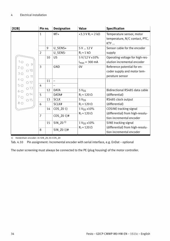
[X2B] Pin no. Designation Value Specification
1 MT+ +3.3 V Ri = 2 kΩ Temperature sensor, motor
temperature, N/C contact, PTC,
KTY ...
9 U_SENS+ 5 V … 12 V
RI L 1 kΩ
Sensor cable for the encoder
supply2 U_SENS-
10 US 5 V/12 V ±10%
Imax = 300 mA
Operating voltage for high-res
olution incremental encoder
3 GND 0V Reference potential for en
coder supply and motor tem
perature sensor
11 –
4 –
12 DATA 5 VSS
RI L 120 Ω
Bidirectional RS485 data cable
(differential)5 DATA#
13 SCLK 5 VSS
RI L 120 Ω
RS485 clock output
(differential)6 SCLK#
14 COS_Z0 1) 1 VSS ±10%
RI L 120 Ω
COSINE tracking signal
(differential) from high-resolu
tion incremental encoder7 COS_Z0 1)#
15 SIN_Z0 1) 1 VSS ±10%
RI L 120 Ω
SINE tracking signal
(differential) from high-resolu
tion incremental encoder8 SIN_Z0 1)#
1) Heidenhain encoder: A=SIN_Z0; B=COS_Z0
Tab. 4.10 Pin assignment: Incremental encoder with serial interface, e.g. EnDat – optional
The outer screening must always be connected to the PE (plug housing) of the motor controller.
4 Electrical installation
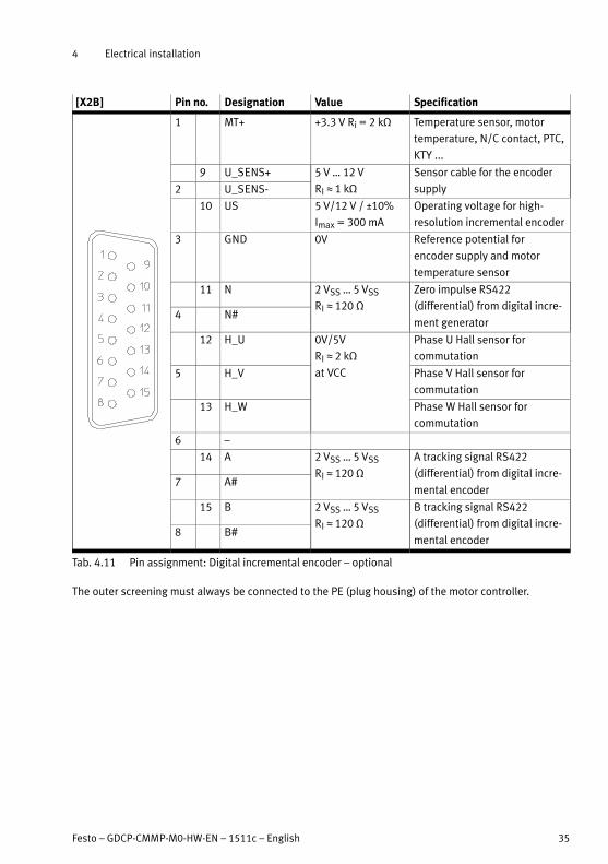
Festo – GDCP-CMMP-M0-HW-EN – 1511c – English 35
[X2B] Pin no. Designation Value Specification
1 MT+ +3.3 V Ri = 2 kΩ Temperature sensor, motor
temperature, N/C contact, PTC,
KTY ...
9 U_SENS+ 5 V … 12 V
RI L 1 kΩ
Sensor cable for the encoder
supply2 U_SENS-
10 US 5 V/12 V / ±10%
Imax = 300 mA
Operating voltage for high-
resolution incremental encoder
3 GND 0V Reference potential for
encoder supply and motor
temperature sensor
11 N 2 VSS … 5 VSS
RI L 120 Ω
Zero impulse RS422
(differential) from digital incre
ment generator4 N#
12 H_U 0V/5V
RI L 2 kΩ
at VCC
Phase U Hall sensor for
commutation
5 H_V Phase V Hall sensor for
commutation
13 H_W Phase W Hall sensor for
commutation
6 –
14 A 2 VSS … 5 VSS
RI L 120 Ω
A tracking signal RS422
(differential) from digital incre
mental encoder7 A#
15 B 2 VSS … 5 VSS
RI L 120 Ω
B tracking signal RS422
(differential) from digital incre
mental encoder8 B#
Tab. 4.11 Pin assignment: Digital incremental encoder – optional
The outer screening must always be connected to the PE (plug housing) of the motor controller.

4 Electrical installation
36 Festo – GDCP-CMMP-M0-HW-EN – 1511c – English
4.6 Connection: CAN bus [X4]
4.6.1 Plug [X4]
Motor controller Design on the device Counterplug
CMMP-AS-...-M0 Sub-D plug connector, 9-pin, pin Sub-D plug connector, 9-pin, socket
Tab. 4.12 Plug design [X4]
4.6.2 Pin assignment [X4]
[X4] Pin no. Designation Value Description
1 – – Not assigned
6 CAN-GND – Galvanically connected to GND in the
motor controller
2 CAN-L – Negative CAN signal (dominant low)
7 CAN-H – Positive CAN signal (dominant high)
3 CAN-GND – Galvanically connected to GND in themotor controller
8 – – Not assigned
4 – – Not assigned
9 – – Not assigned
5 CAN shield – Screening
Tab. 4.13 Pin assignment for CAN-interface [X4]

4 Electrical installation
Festo – GDCP-CMMP-M0-HW-EN – 1511c – English 37
4.7 Connection: Motor [X6]
4.7.1 Plug [X6]
CMMP-AS-... Design on the device / coding Counterplug / coding
...-C2-3A-M0 PHOENIX Contact
MSTBA 2.5/9-G-5.08 BK
Pin 1 (BR-) PHOENIX Contact
MSTB 2.5/9-ST-5.08 BK
Pin 9 (U)
...-C5-3A-M0
...-11A-P3-M0 PHOENIX Power-Combicon
PC 5/9-G-7.62 BK
– PHOENIX Power-Combicon
PC 5/9-ST-7.62 BK
–
...-C10-11A-P3-M0
Tab. 4.14 Plug design [X6]
4.7.2 Pin assignment [X6]
[X6]1) Pin no. Designation Value Specification
1
9
1 Br- 0 V brake Holding brake (motor), signal
level dependent on switching
status, high-side/low-side
switch2 BR+ 24 V brake
3 PE PE Cable shield for the holding
brake and the temperature
sensor (with Festo cables: n.c.)
4 -MTdig GND Motor temperature sensor,
N/C contact, N/O contact, PTC,
KTY ...5 +MTdig +3.3 V 5 mA
6 PE PE Protective earth conductor
from the motor
7 W Technical data
� Tab. A.9
Connection of the three motor
phases8 V
9 U
1) Representation of the plug on the device of the motor controller CMMP-AS-...-3A-M0
Tab. 4.15 Pin assignment [X6] connection: Motor
The shielding for the motor cable must also be attached to the housing of the motor con
troller (spring clip: Fig. 2.5 � Page 18).
A motor holding brake can be connected to terminals BR+ and BR-. The locking brake is supplied from
the logic supply of the motor controller. The maximum output current provided by the CMMP-AS-...-M0
motor controller must be observed.
4 Electrical installation
38 Festo – GDCP-CMMP-M0-HW-EN – 1511c – English
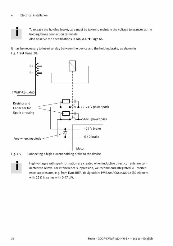
To release the holding brake, care must be taken to maintain the voltage tolerances at the
holding brake connection terminals.
Also observe the specifications in Tab. A.4 � Page 66.
It may be necessary to insert a relay between the device and the holding brake, as shown in
Fig. 4.5� Page 38:
CMMP-AS-...-M0
BR+
Br-
Resistor and
Capacitor for
Spark arresting
+24 V power pack
GND power pack
+24 V brake
GND brake
Motor
Free-wheeling diode
Fig. 4.5 Connecting a high-current holding brake to the device
High voltages with spark formation are created when inductive direct currents are con
nected via relays. For interference suppression, we recommend integrated RC interfer
ence suppressors, e.g. from Evox RIFA, designation: PMR205AC6470M022 (RC element
with 22 Ω in series with 0.47 μF).

4 Electrical installation
Festo – GDCP-CMMP-M0-HW-EN – 1511c – English 39
4.8 Connection: Voltage supply [X9]
The motor controller CMMP-AS-...-M0 receives its 24 V DC power supply for the control electronics via
the plug connector [X9].
The main power supply for the motor controllers CMMP-AS-…-3A-M0 is 1-phase and for the motor con
trollers CMMP-AS-…-11A-P3-M0 3-phase.
4.8.1 Plug
CMMP-AS-... Design on the device / coding Counterplug / coding
...-C2-3A-M0 PHOENIX Contact
MSTBA 2.5/9-G-5.08-BK
Pin 9
(GND24V)
PHOENIX Contact
MSTB 2.5/9-ST-5.08-BK
Pin 1
(L)...-C5-3A-M0
...-C5-11A-P3-M0 PHOENIX Power-COMBICON
PC 5/11-G-7.62-BK
– PHOENIX Power-COMBICON
PC 5/11-ST-7.62-BK
–
...-C10-11A-P3-M0
Tab. 4.16 Plug design [X9]
4.8.2 Pin assignment [X9] – single-phase
[X9]1) Pin no. Designation Value Specification
1
9
1 L 100 … 230 V AC
±10%
50 … 60 Hz
Mains phase
2 N Mains neutral conductor (refer
ence potential)
3 ZK+ 60 … 380 V DC Alternative supply:
Positive intermediate circuit
voltage
4 ZK- GND_ZK Alternative supply:
Negative intermediate circuit
voltage
5 BR-INT 460 V DC Internal braking resistor connec
tion (bridge after BR-CH when
using the internal resistor).
6 BR-CH 460 V DC Brake chopper connection for
– internal braking resistor to
ward BR-INT – or –
– external braking resistor
against ZK+
7 PE PE Connection for protective
conductor from the mains
8 +24 V +24 V DC ±20% Supply for control section, holding
brake and I/O
9 GND24 V GND24 V DC Reference potential for supply 0V
1) Representation of the contact strip on the motor controller CMMP-AS-...-3A-M0
Tab. 4.17 Pin assignment [X9] – single-phase
4 Electrical installation
40 Festo – GDCP-CMMP-M0-HW-EN – 1511c – English
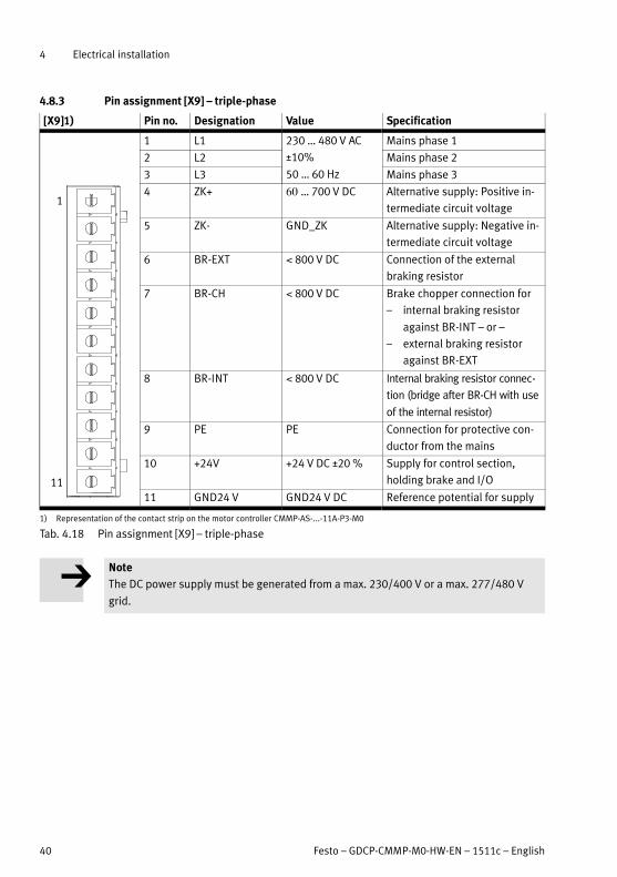
4.8.3 Pin assignment [X9] – triple-phase
[X9]1) Pin no. Designation Value Specification
1
11
1 L1 230 … 480 V AC
±10%
50 … 60 Hz
Mains phase 1
2 L2 Mains phase 2
3 L3 Mains phase 3
4 ZK+ … 700 V DC Alternative supply: Positive in
termediate circuit voltage
5 ZK- GND_ZK Alternative supply: Negative in
termediate circuit voltage
6 BR-EXT 800 V DC Connection of the external
braking resistor
7 BR-CH 800 V DC Brake chopper connection for
– internal braking resistor
against BR-INT – or –
– external braking resistor
against BR-EXT
8 BR-INT 800 V DC Internal braking resistor connec
tion (bridge after BR-CH with use
of the internal resistor)
9 PE PE Connection for protective con
ductor from the mains
10 +24V +24 V DC ±20 % Supply for control section,
holding brake and I/O
11 GND24 V GND24 V DC Reference potential for supply
1) Representation of the contact strip on the motor controller CMMP-AS-...-11A-P3-M0
Tab. 4.18 Pin assignment [X9] – triple-phase
Note
The DC power supply must be generated from a max. 230/400 V or a max. 277/480 V
grid.

4 Electrical installation
Festo – GDCP-CMMP-M0-HW-EN – 1511c – English 41
4.8.4 Mains fuse
In the mains power supply cable, an automatic circuit breaker is installed for protection of the line:
Motor controller Phases Mains fuse1)
CMMP-AS-C2-3A-M0 1 B10
CMMP-AS-C5-3A-M0 1 B16
CMMP-AS-C5-11A-P3-M0 3 B16
CMMP-AS-C10-11A-P3-M0 3 B16
1) The required fuse is dependent, among other things, on the cable cross section, ambient temperature and laying procedure.
Observe the following instructions!
Tab. 4.19 Required mains fuses
In designing the fuses, also observe the following standards:
� EN 60204-1 “Safety of machinery – Electrical equipment of machines – Part 1:
General requirements”
� Take into consideration the legal regulations applicable for the destination as well as:
– Regulations and standards,
– Regulations of the testing organisations and insurers,
– national specifications.
4.8.5 AC supply
Switch-on behaviour:
– As soon as the motor controller CMMP-AS-...-M0 is provided with mains voltage, the intermediate
circuit is charged ( 1 s) via the braking resistors, with the intermediate circuit relay deactivated.
– After the intermediate circuit has been pre-charged, the relay engages and the intermediate circuit
without resistors is connected directly to the mains supply.
AC supply with active PFC
The PFC step is available only for 1-phase motor controllers (CMMP-AS-...-3A-M0).
Note
Operation with mains line choke is not permissible, since the control circuit could be
stimulated to oscillate.
Note
Operation with isolating transformer is not permissible as no reference potential (N) is
available.

4 Electrical installation
42 Festo – GDCP-CMMP-M0-HW-EN – 1511c – English
Note
When the load voltage is switched on, ensure that the reference potential (N) is
switched before the phase (L1). This can be achieved through:
– unswitched reference potential (N)
– use of fuses with leading N when switching of the reference potential is specified.
DC supply - intermediate circuit coupling
A direct DC power supply can be used for the intermediate circuit as an alternative to AC power or for
achieving intermediate circuit coupling.
The intermediate circuits of several identically constructed motor controllers (CMMP-AS-...-3A-M0/-M3
or CMMP-AS-...-11A-P3-M0/-M3) can be connected via the terminals ZK+ and ZK- at plug connector
[X9]. Coupling of the intermediate circuits is useful in applications where high braking energies occur or
where motion must still be performed when the power supply fails.
Note
For 1-phase motor controllers (CMMP-AS-...-3A-M0), the PFC step must be deactivated
when the motor controller is coupled through the intermediate circuit.
Note
If the intermediate circuits are coupled, it is imperative that all of the motor controllers
are supplied via the same phase (e.g. L1) � Example Fig. 4.6.
Otherwise, the motor controllers will be damaged due to the resulting voltage at the
rectifiers.
The maximum number of coupled motor controllers is limited by the power of the sup
ply. Pay attention to a symmetrical load of the network here.

4 Electrical installation
Festo – GDCP-CMMP-M0-HW-EN – 1511c – English 43
PE
BR-CH
BR-INT
ZK+
ZK-
L
N
24V+
GND24V
X9
Single-phase
L
N
0 V
PE
+24 V
PE
BR-CH
BR-INT
ZK+
ZK-
L
N
24V+
GND24V
X9
Single-phasePower circuit
breakers
Power circuit
breakers
Fig. 4.6 Example of intermediate circuit coupling with common supply, single-phase
Fig. 4.6 is a schematic representation; note the information for mains fuses in
� Section 4.8.4.
4.8.6 Braking resistor
If no external braking resistor is used, a bridge to the internal braking resistor must be
connected in order for the intermediate circuit quick discharge to function! � Tab. 4.17 or
Tab. 4.18.
For larger braking power an external braking resistor must be connected [X9]
� Section 4.7.2 and Fig. 4.5.
The motor controller detects the external brake resistance automatically as soon as the intermediate
circuit voltage rises above the response threshold (� A.1, Tab. A.6).
After that, a connected external brake resistance can also be displayed in the configuration software.
4 Electrical installation
44 Festo – GDCP-CMMP-M0-HW-EN – 1511c – English
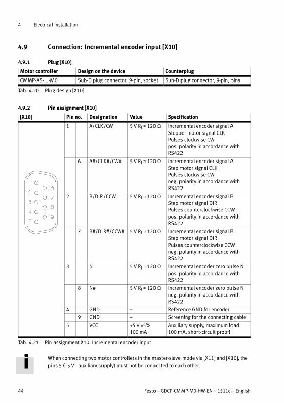
4.9 Connection: Incremental encoder input [X10]
4.9.1 Plug [X10]
Motor controller Design on the device Counterplug
CMMP-AS-...-M0 Sub-D plug connector, 9-pin, socket Sub-D plug connector, 9-pin, pins
Tab. 4.20 Plug design [X10]
4.9.2 Pin assignment [X10]
[X10] Pin no. Designation Value Specification
1 A/CLK/CW 5 V RI L 120 Ω Incremental encoder signal A
Stepper motor signal CLK
Pulses clockwise CW
pos. polarity in accordance with
RS422
6 A#/CLK#/CW# 5 V RI L 120 Ω Incremental encoder signal A
Step motor signal CLK
Pulses clockwise CW
neg. polarity in accordance with
RS422
2 B/DIR/CCW 5 V RI L 120 Ω Incremental encoder signal B
Step motor signal DIR
Pulses counterclockwise CCW
pos. polarity in accordance with
RS422
7 B#/DIR#/CCW# 5 V RI L 120 Ω Incremental encoder signal B
Step motor signal DIR
Pulses counterclockwise CCW
neg. polarity in accordance with
RS422
3 N 5 V RI L 120 Ω Incremental encoder zero pulse N
pos. polarity in accordance with
RS422
8 N# 5 V RI L 120 Ω Incremental encoder zero pulse N
neg. polarity in accordance with
RS422
4 GND – Reference GND for encoder
9 GND – Screening for the connecting cable
5 VCC +5 V ±5%
100 mA
Auxiliary supply, maximum load
100 mA, short-circuit proof!
Tab. 4.21 Pin assignment X10: Incremental encoder input
When connecting two motor controllers in the master-slave mode via [X11] and [X10], the
pins 5 (+5 V - auxiliary supply) must not be connected to each other.

4 Electrical installation
Festo – GDCP-CMMP-M0-HW-EN – 1511c – English 45
4.9.3 Type and design of the cable [X10]
We recommend use of the encoder connection lines in which the incremental encoder signal is twisted
by pairs and the individual pairs are screened.
4.9.4 Connection instructions [X10]
Input [X10] can be used for processing incremental encoder signals and also for pulse direction signals
as generated by stepper motor controller cards.
The input amplifier at the signal input is designed for processing differential signals as per the RS422
interface standard.
4.10 Connection: Incremental encoder output [X11]
4.10.1 Plug [X11]
Motor controller Design on the device Counterplug
CMMP-AS-...-M0 Sub-D plug connector, 9-pin, socket Sub-D plug connector, 9-pin, pins
Tab. 4.22 Plug design [X11]
4.10.2 Pin assignment [X11]
[X11] Pin no. Designation Value Specification
1 A 5 V RA L 66 Ω1) Incremental encoder signal A
6 A# 5 V RA L 66 Ω1) Incremental encoder signal A#
2 B 5 V RA L 66 Ω1) Incremental encoder signal B
7 B# 5 V RA L 66 Ω1) Incremental encoder signal B#
3 N 5 V RA L 66 Ω1) Incremental encoder zero
pulse N
8 N# 5 V RA L 66 Ω1) Incremental encoder zero
pulse N#
4 GND - Reference GND for encoder
9 GND - Screening for connecting
cable
5 VCC +5 V ±5% 100 mA Auxiliary supply, maximum
load 100 mA, short-circuit
proof!
1) The specification for RA designates the differential output resistance
Tab. 4.23 Pin assignment [X11]: Incremental encoder output
The output driver at the signal output provides differential signals (5 V) as per the RS422 interface standard.
Up to 32 other controllers can be addressed by one device.
When connecting two motor controllers in the master-slave mode via [X11] and [X10], the
pins 5 (+5 V - auxiliary supply) must not be connected to each other.
4 Electrical installation
46 Festo – GDCP-CMMP-M0-HW-EN – 1511c – English
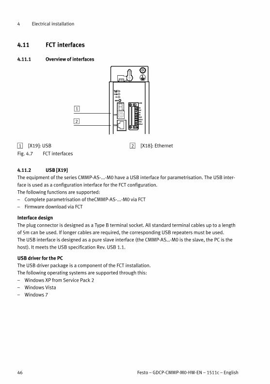
4.11 FCT interfaces
4.11.1 Overview of interfaces
1
2
1 [X19]: USB 2 [X18]: Ethernet
Fig. 4.7 FCT interfaces
4.11.2 USB [X19]
The equipment of the series CMMP-AS-...-M0 have a USB interface for parametrisation. The USB inter
face is used as a configuration interface for the FCT configuration.
The following functions are supported:
– Complete parametrisation of theCMMP-AS-...-M0 via FCT
– Firmware download via FCT
Interface design
The plug connector is designed as a Type B terminal socket. All standard terminal cables up to a length
of 5m can be used. If longer cables are required, the corresponding USB repeaters must be used.
The USB interface is designed as a pure slave interface (the CMMP-AS…-M0 is the slave, the PC is the
host). It meets the USB specification Rev. USB 1.1.
USB driver for the PC
The USB driver package is a component of the FCT installation.
The following operating systems are supported through this:
– Windows XP from Service Pack 2
– Windows Vista
– Windows 7

4 Electrical installation
Festo – GDCP-CMMP-M0-HW-EN – 1511c – English 47
4.11.3 Ethernet TCP/IP [X18]
The equipment of the series CMMP-AS-...-M0 have a USB interface for parametrisation.
The following functions are supported:
– Point-to-point communication between PC and motor controller for parametrisation
– Complete parametrisation of theCMMP-AS-...-M0 via FCT
– Communication from one PC or one PLC to several CMMP-AS-...-M0 that are located in the same
local network for the purpose of monitoring, adaptation of the parametrisation or also process con
trol of the controller via Modbus TCP.
Note
Unauthorised access to the device can cause damage or malfunctions.
When connecting the device to a network:
� Protect the network from unauthorised access.
Measures for protecting the network include:
– Firewall
– Intrusion Prevention System (IPS)
– Network segmentation
– Virtual LAN (VLAN)
– Virtual private network (VPN)
– Security at physical access level (Port Security).
For further information � Guidelines and standards for security in information techno
logy, e.g. IEC 62443, ISO/IEC 27001.
Interface design
The interface in the device is designed as an 8P8C socket (RJ45).
The connection has two LEDs with the following function:
– Yellow Physical Link Detect (network connection available)
– Green Data Connection (data connection / data exchange)
The interface is designed to conform to the IEEE 802.3u specification. Cables of type FTP5 or high-order
must be used with 100Base-TX. The interface supports the autosensing function for automatic identi
fication of the connected cable. Both standard patch cables (1:1) and Crosslink (crossed) cables can be
used.
Supported services
The following services are supported by the Ethernet interface:
– TCP/IP
– UDP/IP
– DNS (ARP and BOOTP)
– DHCP
– AutoIP
– TFTP
TFTP must be activated separately in Windows if necessary and a pass rule defined in the
Firewall.

4 Electrical installation
48 Festo – GDCP-CMMP-M0-HW-EN – 1511c – English
Address allocation
The network settings (IP address, subnetwork mask, gateway) can either be automatically obtained or
manually specified:
– Automatically via DHCP (the automatically obtained IP address lies in the IP range specified by the
DHCP server)
– Automatically via Auto IP (if no DHCP server was found, an address between 169.254.1.0 and
169.254.254.255 is selected pseudorandomly)
– Manual IP assignment (manual setting of the network parameters via FCT)
The following sequence applies for connection set-up:
1. DHCP
2. AutoIP
3. Static IP address
If no IP address can be obtained via the higher-level service, the following service is used. Thus if no
address can be obtained via DHCP, first an AutoIP and then a static address is used.

4 Electrical installation
Festo – GDCP-CMMP-M0-HW-EN – 1511c – English 49
4.12 Connection: I/O interface for STO [X40]
4.12.1 Plug [X40]
Motor controller Design on the device Counterplug
CMMP-AS-...-M0 PHOENIX MINICOMBICON MC
1.5/8-GF-3.81 BK
PHOENIX MINICOMBICON MC
1.5/8-STF-3.81 BK
Tab. 4.24 Plug design [X40]
4.12.2 Pin assignment [X40]
[X40]1) Pin no. Designation Value Specification
8 0 V 0 V Reference potential for auxiliary power
supply.
7 24 V +24 V DC Output for auxiliary power supply (24 V DC
logic supply of the motor controller
brought out).
6 C2 – Feedback contact for the status “STO” on
an external controller.5 C1
4 0V-B 0V Reference potential for STO-B.
3 STO-B 0 V / 24 V Control port B for the function STO.
2 0V-A 0 V Reference potential for STO-A.
1 STO-A 0V / 24V Control port A for the function STO.
1) Representation of the plug on the device of the motor controller CMMP-AS-...-M0
Tab. 4.25 Pin assignment [X40]: I/O interface for STO
4.12.3 Circuitry with use of the STO safety function [X40]
To work safely with the safety function STO – “Safe Torque Off ”, please observe the in
formation in the documentation � GDCP-CMMP-AS-M0-S1-... .
4.12.4 Circuitry without use of the STO safety function [X40]
If you do not need the integrated safety function STO in your application, to operate the
motor controller you must connect the X40 interface, as depicted in Fig. 4.8.
This deactivates the integrated safety function!
When using this circuitry for the CMMP-AS-...-M0, safety in the application must be en
sured through other appropriate measures.

4 Electrical installation
50 Festo – GDCP-CMMP-M0-HW-EN – 1511c – English
Note
Loss of the safety function!
Lack of the safety function can result in serious, irreversible injuries, e.g. due to uncon
trolled movements of the connected actuator technology.
Bypassing of safety equipment is impermissible.
Make sure that no jumpers or the like can be used parallel to safety wiring, e.g. through use of
maximum wire cross sections or appropriate wire end sleeves with insulating collars.
Use twin wire end sleeves for looping through lines between neighbouring equipment.
3
5
21
DC
DC
STO-A
0V-A
24V
0V
DC
DC
STO-B
0V-B
3x
U, V, W
+V DC
+VDC
43
1 Integrated safety function STO
2 Power output stage in CMMP-AS-…-M0
(only one phase shown)
3 Driver supply
4 Motor connection
5 Voltage supply
Fig. 4.8 Circuitry without use of the safety function – functional principle
4 Electrical installation
Festo – GDCP-CMMP-M0-HW-EN – 1511c – English 51
4.13 Instructions on safe and EMC-compliant installation
4.13.1 Explanations and terms
Electromagnetic compatibility (EMC) or electromagnetic interference (EMI) involves the following re
quirements:
Resistance to interference
Sufficient interference immunity of an electrical system or electrical device against external electrical,
magnetic or electromagnetic noise via lines or space.
Emitted interference
Sufficiently low emitted interference of electrical, magnetic or electromagnetic interference of an elec
trical system or an electrical device on other devices in the environment via cables and space.
Warning
All PE protective earth conductors must always be connected prior to commissioning for
reasons of safety.
The mains-side PE connection is made to the PE connection points (device rear wall) and
[X9] of the CMMP-AS-...-M0.
Make sure that the earth connections between devices and the mounting plate are of
sufficiently large dimensions in order to be able to discharge HF interference.
4.13.2 General remarks on EMC
Interference emission and resistance to interference of a motor controller always depend on the com
plete design of the drive, which consists of the following components:
– Voltage supply
– Motor controller
– Motor
– Electromechanical components
– Design and type of wiring
– Connection to the higher-order controller
Mains filter
Motor controllers and mains filters are provided to increase the interference immunity and to reduce
the level of emitted interference.
Motor controller Mains filter
CMMP-AS-C2-3A-M0 In order to increase the interference immunity and decrease the
level of emitted interference, the motor controller already has
integrated motor chokes and mains filters, which means that it can
be operated without additional shielding and filters in most appli
cations.
CMMP-AS-C5-3A-M0
CMMP-AS-C5-11A-P3-M0
CMMP-AS-C10-11A-P3-M0
Tab. 4.26 Mains filter

4 Electrical installation
52 Festo – GDCP-CMMP-M0-HW-EN – 1511c – English
The motor controllers CMMP-AS-...-M0 have been checked in accordance with EMC
product standard EN 61800-3 that is applicable to electric drives. The standard compon
ents from the Festo accessories were used for qualification. EMC can only be guaranteed
if the motor and encoder or resolver cables from Festo are used and not extended or
changed in any other form.
In the majority of cases, no external filter measures are required (� Section 4.13.3,
Tab. 4.27).
The declaration of conformity is available at � www.festo.com.
4.13.3 EMC areas: First and second environment
If installed correctly and if all connecting cables are wired correctly, the CMMP-AS-...-M0 motor control
lers fulfil the specifications of the related product standard EN 61800-3. This standard no longer refers
to limit value classes, but to so-called environments.
Note
The first environment (C2) includes electricity grids connected to residential housing;
the second environment (C3) includes grids connected only to industrial plants.
The device may generate high frequency interference, which may make it necessary to
implement interference suppression measures in residential areas.
Applicable for the motor controller CMMP-AS-...-M0:
EMC class Area Compliance with EMC requirements
Emitted
interference
Second environ
ment (industrial)
Motor cable lengths up to 25 m without external filters.
A suitable mains filter must be installed when longer mo
tor cables of 25 … 50 m are used.
Resistance to
interference
Second environ
ment (industrial)
Independent of the motor cable length.
Tab. 4.27 EMC requirements

4 Electrical installation
Festo – GDCP-CMMP-M0-HW-EN – 1511c – English 53
4.13.4 EMC-compliant wiring
The following must be observed for EMC-compliant design of the drive system
(see also chapter 4.2 � Page 25):
Cable interfaces on the CMMP-AS-...-M0
Port Interface Cable length [m] Comment
X1 I/O communication 5 Recommendation: Screened
X2A Resolver 50 screened
X2B Encoder 50 screened
X4 CAN 40 at 1 Mbit/s (permissible line length
dependent on the bit rate)
X6 Motor 25 screened (� Tab. 4.27)
X9 Power supply 2 –
X10 Increment generator input 30 screened
X11 Increment generator output 5 screened
X18 Ethernet 10 at least CAT-5
X19 USB 5 in accordance with USB specification
Rev. USB 1.1
X40 Safety function ST0 30 –
Tab. 4.28 Permissible cable lengths on the CMMP-AS-...-M0
1. To keep leaked current and losses in the motor cable as low as possible, the motor controller
CMMP-AS-...-M0 should be placed as close to the motor as possible (� Chapter 4.13.5 � Page 55).
2. Motor and encoder cable must be screened.
3. The screening of the motor cable is attached to the housing of the motor controller CMMP-AS-...-M0
(screened connection terminals, spring clips). The cable screening is also always attached to the
corresponding motor controller to prevent leaked current flowing back to the controller which
caused it.
4. The mains-side PE connection is connected to the PE connection point of the power supply [X9] and
to the PE connection of the housing.
5. The PE internal conductor of the motor cable is connected to the PE connection point of the motor
connection [X6].
6. Signal lines must be separated as far as possible from the power cables. They should not be routed
parallel to one another. If crossovers are unavoidable, they should be made as close to vertical (i.e.
at a 90° angle) as possible.
7. For unscreened signal and control lines, safe/reliable operation cannot be guaranteed. If they must
be used, they should at least be twisted.
8. Even screened cables always have short unscreened parts at both ends (unless a screened plug
housing is used).
In general:
– Connect the inner screenings to the pins of the plug connectors provided for the purpose; length
maximum 40 mm.
– Length of the unscreened wires with self-made cables, maximum 35 mm.
– Connect entire screening on the controller side flush to the PE terminal; maximum length 40 mm.

4 Electrical installation
54 Festo – GDCP-CMMP-M0-HW-EN – 1511c – English
– Connect entire screening flush at the motor to the plug or motor housing; length maximum 40 mm
(guaranteed with NEBM-...).
Danger
All PE protective earth conductors must always be connected prior to commissioning for
reasons of safety.
The regulations of EN 50178 and EN 60204-1 for protective grounding must always be
observed during installation!
4 Electrical installation
Festo – GDCP-CMMP-M0-HW-EN – 1511c – English 55
4.13.5 Operation with long motor cables
For applications in combination with long motor cables and/or if the wrong motor cables are selected
with excessive cable capacity, the filters may be subjected to thermal overload. To avoid this, it is ne
cessary to enter the cable length used in the application in the FCT parametrisation software. By using
this information the FCT plug-in then automatically calculates the optimal cycle time for the current
regulator and PWM control. The following restrictions are taken into consideration:
Cable length Restrictions in the FCT plug-in CMMP
≤ 15 m – The minimum value for “cycle time current regulator” is 62.5 μs.1)
– The option “half output stage frequency” is set and can be edited.2)
, 15 m, ≤ 25 m – The minimum value for “cycle time current regulator” is 62.5 μs.1)
– The option “half output stage frequency” is set and cannot be edited.
, 25 m – The minimum value for “cycle time current regulator” is 125 μs and cannot be
edited.
– The option “half output stage frequency” is set and cannot be edited.
1) The actual value is automatically determined by the FCT based on the motor controller axis combination.
2) The ability to edit the option “half output stage frequency” does not apply to three-phase controllers.
Tab. 4.29 Restrictions in the FCT plug-in depending on the cable length
In addition, the following procedure is strongly recommended for applications in which long motor
cables are required:
– From a cable length of , 25 m, use only cables with a capacitance between the motor phase and
screening of < 200 pF/m, or better, < 150 pF/m and also use a mains filter!
Note
Longer cable lengths result in deviations to the current regulator amplification (line
resistance).
4.13.6 ESD protection
Caution
Unused Sub-D plug connectors present a danger of damage to the device or to other
parts of the system as a result of ESD (electrostatic discharge).
In the design of the motor controller CMMP-AS-...-M0, great importance has been placed on high resist
ance to interference. For this reason, individual function blocks are galvanically separated from each
other. Signal transmission within the device is performed via an optocoupler.
A distinction is made between the following separated areas:
– Output stage with intermediate circuit and mains input
– Control electronics with analogue signal processing
– 24 V supply and digital inputs and outputs

5 Commissioning
56 Festo – GDCP-CMMP-M0-HW-EN – 1511c – English
5 Commissioning
5.1 General connection instructions
As the installation of the connecting cables is critical for EMC, the preceding chapter
4.13.4 � Page 53 must be observed!
Observe the instructions on commissioning the safety function STO – “Safe Torque Off ” in
the documentation � GDCP-CMMP-AS-M0-S1-... .
Warning
Non-compliance with the safety instructions in chapter 1 � Page 9 can result in materi
al damage, injury, electric shock, or in extreme cases, fatality.
5.2 Tools / material
– Slotted head screwdriver size 1
– USB or EtherNet cable for parameterisation
– Encoder cable
– Motor cable
– Power supply cable
– Control cable
5.3 Connecting the motor
1. Connect motor cable on the motor side.
2. Insert the PHOENIX plug into the socket [X6] on the device.
3. Clamp the cable shields to the shield terminals (not suitable as strain-relief ).
4. Connect encoder cable on the motor side.
5. Insert the Sub-D plug connector into socket [X2A] resolver or [X2B] encoder of the device and tight
en the locking screws.
6. Check all plug connectors once again.

5 Commissioning
Festo – GDCP-CMMP-M0-HW-EN – 1511c – English 57
5.4 Connect motor controller CMMP-AS-...-M0 to the power supply
Warning
Danger of electric shock.
– When cables are not mounted to the plugs [X6] and [X9].
– When connecting cables are disconnected when powered.
Touching live parts causes severe injuries and can lead to death.
The product may only be operated in a built-in status and when all protective measures
have been initiated.
Before touching live parts during maintenance, repair and cleaning work and when there
have been long service interruptions:
1. Switch off power to the electrical equipment via the mains switch and secure it
against being switched on again.
2. After switch-off, wait at least 5 minutes discharge time and check that power is
turned off before accessing the controller.
1. Make sure that the power supply is switched off.
2. Connect the PE cable of the mains supply to the PE earth socket.
3. Insert the PHOENIX plug into the socket [X9] of the motor controller.
4. Connect 24 V connections with appropriate power pack.
5. Make the network power supply connections.
6. Check all plug connectors once again.
5.5 Connecting a PC
1. Connect PC via USB � 4.11.2 USB [X19] or Ethernet � 4.11.3 Ethernet TCP/IP [X18] to the motor
controller.

5 Commissioning
58 Festo – GDCP-CMMP-M0-HW-EN – 1511c – English
5.6 Check operating status
1. Make sure that the controller enable is switched off (controller enable: DIN 5 at [X1]).
2. Switch on the power supplies of all equipment.
During the boot process, the point of the 7-segment display lights up.
After completion of the boot process, the READY-LED lights up green.
If the READY LED lights up red, there is a malfunction. If an “E” appears in the 7-segment
display followed by a sequence of numbers, this is an error message and you must rectify
the cause of the error. In this case, continue to read in the chapter A � Page 65.
If no indicator lights up on the device, execute the following steps:
1. Switch off the power supply.
2. Wait 5 minutes to allow the intermediate circuit to discharge.
3. Check all connecting cables.
4. Check that the 24 V power supply is functional.
5. Switch on the power supply again.
6. If still no indicator lights up � Device is defective.

6 Service functions and diagnostic messages
Festo – GDCP-CMMP-M0-HW-EN – 1511c – English 59
6 Service functions and diagnostic messages
6.1 Protective and service functions
6.1.1 Overview
The motor controller CMMP-AS-...-M0 has a complex array of sensors that monitor the controller sec
tion, power output stage, motor and external communication to ensure that they function excellently.
All diagnostic events which occur are saved in the internal diagnostic memory. Most errors cause the
controller section to switch off the motor controller and the power output stage. The motor controller
cannot be switched back on until the error is remedied and then acknowledged.
A complex system of sensors and numerous monitoring functions ensure operational reliability:
– Measurement of the motor temperature
– Measurement of the power output stage temperature
– Earth fault detection (PE)
– Detection of short-circuits between two motor phases
– Detection of overvoltages in the intermediate circuit
– Detection of faults in the internal voltage supply
– Collapse of supply voltage
– Detection of faults in conjunction with the functional safety engineering ( [X40] )
6.1.2 Phases and mains failure detection
The motor controllers CMMP-AS-...-11A-P3-M0 detect a phase failure in three-phase operation (phase
failure detection) or failure of several phases (network failure detection) of the mains supply at the
device.
6.1.3 Overload current and short-circuit monitoring
Overload current and short-circuit monitoring detects short circuits between two motor phases and
short circuits at the motor output terminals against the positive and negative reference potential of the
intermediate circuit and against PE. If the error control detects overload current, the power output
stage shuts down immediately, guaranteeing protection against short circuits.
6.1.4 Overvoltage monitoring for the intermediate circuit
The overvoltage monitoring for the intermediate circuit takes effect as soon as the intermediate circuit
voltage exceeds the operating voltage range. The power output stage is then deactivated.
6.1.5 Temperature monitoring for the heat sink
The heat sink temperature of the output end stage is measured with a linear temperature sensor. The
temperature limit varies between the device performance classes � Tab. A.3 on page 66.
A temperature warning is triggered approx. 5 °C below the limit value.
6 Service functions and diagnostic messages
60 Festo – GDCP-CMMP-M0-HW-EN – 1511c – English
6.1.6 Monitoring of the motor
The motor controller CMMP-AS-...-M0 has the following protective functions for monitoring the motor
and the connected shaft encoder:
Protective function Description
Monitoring the shaft
encoder
An error of the shaft encoder results in switching off of the power output
stage. For the resolver, for example, the tracking signal is monitored. For in
cremental encoders, the commutation signals are checked. Generally true for
intelligent encoders is that their various error messages are evaluated and
reported to the CMMP-AS-...-M0 as common error E 08-8.
Measurement and
monitoring of the
motor temperature
The motor controller CMMP-AS-...-M0 has a digital and an analogue input for
recording and monitoring the motor temperature. They are selectable as tem
perature sensors.
– [X6]: Digital input for PTCs, N/C contacts and N/O contacts.
– [X2A] and
[X2B]:
N/C contact and KTY series analogue sensors. Other
sensors (NTC, PTC) require a corresponding software
adaptation as needed.
Tab. 6.1 Protective functions of the motor
6.1.7 I2t monitoring
The motor controller CMMP-AS-...-M0 has I2t monitoring to limit the average power loss in the power
end stage and in the motor. Since the power loss that occurs in the power electronics and the motor
can, in the worst case, grow at a rate equal to the square of the flowing current, the squared current
value is taken as a measure for the power loss.
6.1.8 Power monitoring for the brake chopper
The braking resistors are monitored on the firmware side through the function I2t brake chopper. When
the power monitoring “I²t brake chopper” of 100% is reached, the output of the internal braking resist
or is limited to the rated output.
Note
As a result of this switch-back, the error “E 07-0” “Overvoltage in the intermediate circuit” is
generated. If the braking process is not completed, the residual energy is fed back to the
motor controller and results in an uncontrolled running out of the drive if no automatic lock
ing mechanical system, clamping units or weight compensation is used.
This can result in damage to the machine. Connection of an appropriate clamping unit to
prevent an uncontrolled running out of the drive at the motor controller is recommended.
In addition, the brake chopper is protected by means of overcurrent detection. If a short circuit is detec
ted via the braking resistor, the brake chopper controller is switched off.

6 Service functions and diagnostic messages
Festo – GDCP-CMMP-M0-HW-EN – 1511c – English 61
6.1.9 Commissioning status
Motor controllers sent to Festo for servicing are loaded with other firmware and parameters for testing
purposes.
Before it is commissioned again at the location of the final customer, the motor controller CMMP-
AS-...-M0 must be parametrised. The parametrisation software queries the commissioning status and
prompts the user to parameterise the motor controller. In parallel, the device signals through the visual
indicator ‘A’ on the 7-segment display that, although it is ready for operation, it has not been paramet
erised yet.
6.1.10 Rapid discharge of the intermediate circuit
When a mains supply failure is detected, the intermediate circuit is quickly discharged within the safety
time specified in EN 60204-1.
Delayed connection of the brake chopper by power class in parallel operation and when a mains failure
occurs ensures that the main energy during rapid discharge of the intermediate circuit is taken over
through the braking resistors of the higher power classes.
But the rapid discharge can be ineffective in certain device constellations, especially
when several motor controllers are connected in parallel in the intermediate circuit or a
brake resistance is not connected. The motor controllers may carry dangerous voltage for
up to 5 minutes after being switched off (capacitor residual charge).
6.1.11 Detection of faults in conjunction with the functional safety engineering
– Discrepancy time monitoring STO
– Driver supply monitoring
6.2 Operating mode and diagnostic messages
6.2.1 Operation and display components
The motor controller CMMP-AS-...-M0 has three LEDs on the front and one 7-segment display for show
ing the operating statuses.
Element LED colour Function
7-segment display – Displays the operating mode and a coded error number
should an error occur � Section 6.2.2
LED1 Green Operating status
Red Error
LED2 Green Controller enable
LED3 Yellow CAN bus status display
RESET button – Hardware reset for the processor
Tab. 6.2 Display components and RESET pushbutton

6 Service functions and diagnostic messages
62 Festo – GDCP-CMMP-M0-HW-EN – 1511c – English
6.2.2 7-segment display
The display and the meaning of the symbols shown are illustrated in the following table:
Display1) Meaning
A The motor controller must still be parameterised.
F Signals that firmware is currently being loaded into the flash.
. (flashes) Bootloader active (only the point flashes).
d Signals that a parameter set is currently being loaded from the SD card to
the controller.
H (flashes) “H”: The motor controller is in the “safe status”.
This does not have the same meaning as the information on the status of
the safety function STO (Safe Torque Off ).
H E L L O Display for the function “Identify Controller”.
(rotating) The outer segments are displayed “rotating” in the speed adjustment
operating mode. The display depends on the actual position or speed.
The middle bar is only active when controller enable is active.
I Controlled torque operation.
P x x x Positioning (“xxx” stands for the record number, see below).
000 No positioning active.
001...255 Positioning record 001 ... 255 active.
259/260 Jog positive/negative.
262 CAM-IN / CAM-OUT (cam disc).
264/265 Direct records for manual travel via FCT or FHPP direct operation.
P H x Homing (“x” stands for the homing phase, see below).
0 Phase “Search for reference point”.
1 Phase “Crawl”.
2 Phase “Approach zero point”.
E x x y Error message with main index “xx” and sub-index “y”.
- x x y Warning message with main index “xx” and sub-index “y”. A warning is
shown at least twice on the 7-segments display.
1) Several characters are displayed one after the other.
Tab. 6.3 Operating mode and error display

6 Service functions and diagnostic messages
Festo – GDCP-CMMP-M0-HW-EN – 1511c – English 63
6.2.3 Acknowledgement of error messages
Error messages can be acknowledged through:
– the parametrisation interface
– the fieldbus (control word)
– a decreasing edge at DIN5 [X1]
Controllerenable
DIN5 [X1]
1
“Error active”
1 L 80 ms
Fig. 6.1 Timing diagram: Acknowledge error
Diagnostic events that are parameterised as warnings are automatically acknowledged
when the cause is no longer present.
6.2.4 Diagnostic messages
The significance and their measures for diagnostic messages are summarised in the following chapter:
� Chapter A Technical appendix

7 Maintenance, care, repair and replacement
64 Festo – GDCP-CMMP-M0-HW-EN – 1511c – English
7 Maintenance, care, repair and replacement
7.1 Maintenance and care
Warning
Danger of electric shock.
Touching live parts causes severe injuries and can lead to death. Do not disconnect
connecting cables when powered.
Before touching live parts during maintenance, repair and cleaning work and when there
have been long service interruptions:
1. Switch off power to the electrical equipment via the mains switch and secure it
against being switched on again.
2. After switch-off, wait at least 5 minutes discharge time and check that power is
turned off before accessing the controller.
If used as intended, the product is maintenance-free.
� Clean the outside of the product with a soft cloth.
7.2 Repair
Repair or maintenance of the product is not permissible. If necessary, replace the com
plete product.
7.3 Replacement and disposal
7.3.1 Dismounting and installation
When dismounting, please observe the safety instructions in section 7.1
Information regarding installation can be found here:
– Mounting � Section 3.2.
– Electrical installation � Chapter 4.
– Commissioning � Chapter 5.
7.3.2 Disposal
Observe the local regulations for environmentally appropriate disposal of electronic mod
ules. The product is RoHS-compliant.

A Technical appendix
Festo – GDCP-CMMP-M0-HW-EN – 1511c – English 65
A Technical appendix
A.1 Technical data CMMP-AS-...-M0
General technical data
CMMP-AS- C2-3A-M0 C5-3A-M0 C5-11A-P3-M0 C10-11A-P3-M0
Type of mounting Screwed onto connecting plate
Display 7-segment display
Parameterisation interface USB 1.1
EtherCat TCP/IP
Approvals
CE marking (see declara
tion of conformity)
In accordance with EU Low Voltage Directive
In accordance with EU EMC Directive
In accordance with EU Machinery Directive
Dimensions and weight
Dimensions
(HxWxD)1)
[mm] 202x66x207 227x66x207 252x79x247
Mounting plate
dimensions
[mm] 248x61 297x75
Weight [kg] 2.1 2.2 3.5
1) without plugs, shield screw and screw heads
Tab. A.1 Technical data: General
Transport and storage
CMMP-AS- C2-3A-M0 C5-3A-M0 C5-11A-P3-M0 C10-11A-P3-M0
Temperature
range
[°C] -25 … +70
Tab. A.2 Technical data: Transport and storage

A Technical appendix
66 Festo – GDCP-CMMP-M0-HW-EN – 1511c – English
Operating and environmental conditions
CMMP-AS- C2-3A-M0 C5-3A-M0 C5-11A-P3-M0 C10-11A-P3-M0
Permissible setup altitude above sea level
with rated
output
[m] 1000
with power re
duction1)
[m] 1000 … 2000 (max.)
Air humidity [%] 0 … 90 (non-condensing)
Protection class IP20 (with plugged-in plug connectors at X6 and X9)
IP10 (without plugged-in plug connectors at X6 and X9)
Degree of
contamination
2
Operating tem
perature
[°C] 0 … +40
Operating
temperature with
power reduction
of 2.5 % per
Kelvin
[°C] +40 … +50
Switch-off
temperature,
heat sink power
section
[°C] 100 80 80 80
1) Above 1000 m above sea level Performance reduction of 1% per 100 m
Tab. A.3 Technical data: Operating and environmental conditions
Electrical data logic supply
CMMP-AS- C2-3A-M0 C5-3A-M0 C5-11A-P3-M0 C10-11A-P3-M0
Nominal voltage [V DC] 24 ±20%
Nominal current1) [A] 0.55 0.65 1
Maximum current
for holding brake
[A] 1 2
With higher power requirement of the holding brake � Fig. 4.5 page 38
1) plus current consumption from an existing holding brake and I/Os
Tab. A.4 Technical data: Logic supply
Note
With a warm motor and a supply voltage that is too low (outside of tolerance), the mo
tor's brakes cannot open 100%, which can lead to premature wearing of the brake.

A Technical appendix
Festo – GDCP-CMMP-M0-HW-EN – 1511c – English 67
Electrical data load voltage
CMMP-AS- C2-3A-M0 C5-3A-M0 C5-11A-P3-M0 C10-11A-P3-M0
Number of
phases
1 3
Nominal voltage [V AC] 100 … 230 230 … 480
Nominal voltage
tolerance
[%] ±10 ±10
Mains frequency [Hz] 50 … 60
In continuous
operation, max.
effective nominal
current
[A] 3 6 5.5 11
Intermediate cir
cuit voltage
(without PFC)
[V DC] 310 … 320 560 … 570
Intermediate
circuit voltage
(with PFC)
[V DC] 360 … 380 –
Alternative
DC supply
[V DC] 60 … 380 60 … 700
Performance data of the PFC step with nominal supply voltage of 230 V AC ±10 %
Continuous
output
[W] 500 1000 –
Peak power [W] 1000 2000 –
Performance data of the PFC step with minimal supply voltage of 110 V AC
Continuous
output
[W] 250 500 –
Peak power [W] 500 1000 –
Tab. A.5 Technical data: Load voltage
Below the nominal power supply voltage, the PFC stage power is linearly reduced. These power charac
teristic curves are shown in the following figure.

A Technical appendix
68 Festo – GDCP-CMMP-M0-HW-EN – 1511c – English
PFC output power (kW)
0,25
CM
MP
-AS
-C2
-3A
-...
CM
MP
-AS
-C5
-3A
-...
Mains voltage (Veff )
PFC power
(peak power)
0,5
0,5
1
1 2
PFC power limited by
I²t (50%)
110 200 255
Fig. A.1 Performance characteristics curve of the PFC level
Technical data for brake resistance
CMMP-AS- C2-3A-M0 C5-3A-M0 C5-11A-P3-M0 C10-11A-P3-M0
Trigger level
(without PFC)
[V DC] 389 760
Trigger level
(with PFC)
[V DC] 440 –
Max. voltage
(without PFC)
[V DC] 400 800
Max. voltage
(with PFC)
[V DC] 460 –
Braking resistor, integrated
Resistance value [Ω] 60 68
Pulse power [kW] 2.8 8.5
Continuous
output
[W] 10 20 110
Braking resistor, external
Resistance value [Ω] 50 40
Operating voltage [V] 460 800
Continuous
output
[W] 2500 5000
Tab. A.6 Technical data for brake resistance
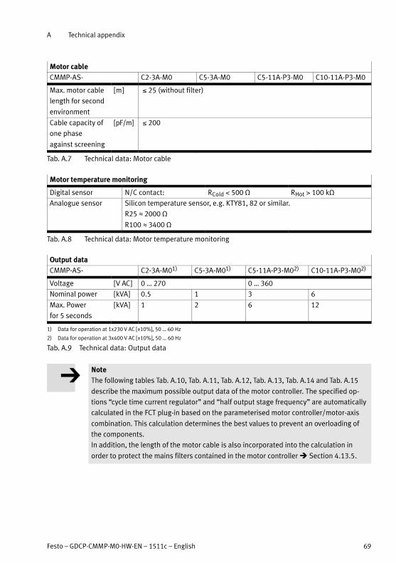
A Technical appendix
Festo – GDCP-CMMP-M0-HW-EN – 1511c – English 69
Motor cable
CMMP-AS- C2-3A-M0 C5-3A-M0 C5-11A-P3-M0 C10-11A-P3-M0
Max. motor cable
length for second
environment
[m] 25 (without filter)
Cable capacity of
one phase
against screening
[pF/m] 200
Tab. A.7 Technical data: Motor cable
Motor temperature monitoring
Digital sensor N/C contact: RCold 500 Ω RHot 100 kΩ
Analogue sensor Silicon temperature sensor, e.g. KTY81, 82 or similar.
R25 L 2000 Ω
R100 L 3400 Ω
Tab. A.8 Technical data: Motor temperature monitoring
Output data
CMMP-AS- C2-3A-M01) C5-3A-M01) C5-11A-P3-M02) C10-11A-P3-M02)
Voltage [V AC] 0 … 270 0 … 360
Nominal power [kVA] 0.5 1 3 6
Max. Power
for 5 seconds
[kVA] 1 2 6 12
1) Data for operation at 1x230 V AC [±10%], 50 … 60 Hz
2) Data for operation at 3x400 V AC [±10%], 50 … 60 Hz
Tab. A.9 Technical data: Output data
Note
The following tables Tab. A.10, Tab. A.11, Tab. A.12, Tab. A.13, Tab. A.14 and Tab. A.15
describe the maximum possible output data of the motor controller. The specified op
tions “cycle time current regulator” and “half output stage frequency” are automatically
calculated in the FCT plug-in based on the parameterised motor controller/motor-axis
combination. This calculation determines the best values to prevent an overloading of
the components.
In addition, the length of the motor cable is also incorporated into the calculation in
order to protect the mains filters contained in the motor controller � Section 4.13.5.

A Technical appendix
70 Festo – GDCP-CMMP-M0-HW-EN – 1511c – English
CMMP-AS-C2-3A-M0
Cycle time current regulator1) [μs] 62.5 125
Half output stage frequency1) active inactive active inactive
Output stage frequency [kHz] 8 16 4 8
Rated output current, effective [A] 2.5 2.2 2.5 2.5
Maximum output current for maximum time (effective value)
Max. output current [A] 5 4.4 5 5
Max. time [s] 5 5 5 5
Max. output current [A] 7.5 6.6 7.5 7.5
Max. time [s] 1.3 1.3 1.3 1.3
Max. output current [A] 10 8.8 10 10
Max. time [s] 0.5 0.5 0.5 0.5
1) Option with FCT able to be parametrised
Tab. A.10 Output data CMMP-AS-C2-3A-M0
CMMP-AS-C5-3A-M0
Cycle time current regulator1) [μs] 62.5 125
Half output stage frequency1) active inactive active inactive
Output stage frequency [kHz] 8 16 4 8
Rated output current, effective [A] 5 4.4 5 5
Maximum output current for maximum time (effective value)
Max. output current [A] 10 8.8 10 10
Max. time [s] 5 5 5 5
Max. output current [A] 15 13.2 15 15
Max. time [s] 1.3 1.3 1.3 1.3
Max. output current, effective [A] 20 17.6 20 20
Max. time [s] 0.5 0.5 0.5 0.5
1) Option with FCT able to be parametrised
Tab. A.11 Output data CMMP-AS-C5-3A-M0
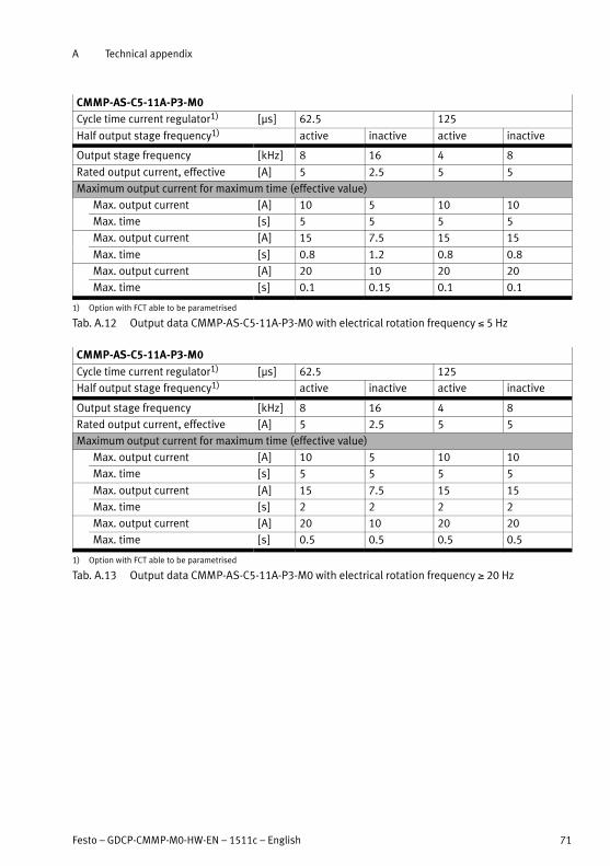
A Technical appendix
Festo – GDCP-CMMP-M0-HW-EN – 1511c – English 71
CMMP-AS-C5-11A-P3-M0
Cycle time current regulator1) [μs] 62.5 125
Half output stage frequency1) active inactive active inactive
Output stage frequency [kHz] 8 16 4 8
Rated output current, effective [A] 5 2.5 5 5
Maximum output current for maximum time (effective value)
Max. output current [A] 10 5 10 10
Max. time [s] 5 5 5 5
Max. output current [A] 15 7.5 15 15
Max. time [s] 0.8 1.2 0.8 0.8
Max. output current [A] 20 10 20 20
Max. time [s] 0.1 0.15 0.1 0.1
1) Option with FCT able to be parametrised
Tab. A.12 Output data CMMP-AS-C5-11A-P3-M0 with electrical rotation frequency 5 Hz
CMMP-AS-C5-11A-P3-M0
Cycle time current regulator1) [μs] 62.5 125
Half output stage frequency1) active inactive active inactive
Output stage frequency [kHz] 8 16 4 8
Rated output current, effective [A] 5 2.5 5 5
Maximum output current for maximum time (effective value)
Max. output current [A] 10 5 10 10
Max. time [s] 5 5 5 5
Max. output current [A] 15 7.5 15 15
Max. time [s] 2 2 2 2
Max. output current [A] 20 10 20 20
Max. time [s] 0.5 0.5 0.5 0.5
1) Option with FCT able to be parametrised
Tab. A.13 Output data CMMP-AS-C5-11A-P3-M0 with electrical rotation frequency 20 Hz

A Technical appendix
72 Festo – GDCP-CMMP-M0-HW-EN – 1511c – English
CMMP-AS-C10-11A-P3-M0
Cycle time current regulator1) [μs] 62.5 125
Half output stage frequency1) active inactive active inactive
Output stage frequency [kHz] 8 16 4 8
Rated output current, effective [A] 8 3.45 10 8
Maximum output current for maximum time (effective value)
Max. output current [A] 16 6.9 20 16
Max. time [s] 5 5 5 5
Max. output current [A] 24 10.35 30 24
Max. time [s] 0.1 0.2 0.1 0.1
Max. output current [A] 32 13.8 40 32
Max. time [s] 0.07 0.15 0.07 0.07
1) Option with FCT able to be parametrised
Tab. A.14 Output data CMMP-AS-C10-11A-P3-M0 with electrical rotation frequency 5 Hz
CMMP-AS-C10-11A-P3-M0
Cycle time current regulator1) [μs] 62.5 125
Half output stage frequency1) active inactive active inactive
Output stage frequency [kHz] 8 16 4 8
Rated output current, effective [A] 8 3.45 10 8
Maximum output current for maximum time (effective value)
Max. output current [A] 16 6.9 20 16
Max. time [s] 5 5 5 5
Max. output current [A] 24 10.35 30 24
Max. time [s] 2 2 2 2
Max. output current [A] 32 13.8 40 32
Max. time [s] 0.5 0.5 0.5 0.5
1) Option with FCT able to be parametrised
Tab. A.15 Output data CMMP-AS-C10-11A-P3-M0 with electrical rotation frequency 20 Hz

A Technical appendix
Festo – GDCP-CMMP-M0-HW-EN – 1511c – English 73
A.1.1 Interfaces
I/O interface [X1]
Digital I/O modules Values Comment
Inputs
DIN0 … DIN9
Input voltage [V] 24 active high, conforming to
EN 61131-2Voltage range [V] 8 … 30
Outputs
DOUT 0 …
DOUT3
Output voltage [V] 24 active high, galvanically isolated
Voltage range1) [V] 8 … 30
Max. output current [mA] 100 per output
+24 V Output voltage [V] 24 –
Max. output current [mA] 100
GND24 Voltage [V] 0 Reference potential for digital
I/Os
1) With use as digital input (configuration with FCT)
Tab. A.16 Technical data: Digital inputs/outputs [X1]
Analogue inputs/outputs Values Comment
AIN0
#AINO
Input section [V] ±10 differential –
Resolution Bit 16
Time delay [μs] 250
Max. input
voltage
[V] 30
RI [kΩ] 30
AIn1 Input section [V] ±10 Single-ended This input can be optionally para
metrised also as a digital input
DIN12 with an 8 V trigger level.1)
Resolution Bit 10
Time delay [μs] 250
AIn2 Input section [V] ±10 Single-ended This input can be optionally para
metrised also as a digital input
DIN13 with an 8 V trigger level.1)
Resolution [Bit] 10
Time delay [μs] 250
AOUT0, AOUT1 Output section [V] ±10 –
Resolution [Bit] 9
Critical frequency [kHz] 1
AGND Voltage [V] 0 Reference potential
+VREF Output section [V] 0 … 10 Reference output for setpoint po
tentiometer
1) Configuration with FCT. Observe note � Section 4.3.3
Tab. A.17 Technical data: Analogue inputs/outputs [X1]

A Technical appendix
74 Festo – GDCP-CMMP-M0-HW-EN – 1511c – English
Resolver connection [X2A]
Resolver connection Values Meaning
S1
S3
Input voltage1) [V] 3.5 COSINE+
COSINE-Input frequency [kHz] 5 … 10
Internal resistance Ri [kΩ] 5
S2
S4
Input voltage1) [V] 3.5 SINE+
SINE-Input frequency [kHz] 5 … 10
Internal resistance Ri [kΩ] 5
R1 Voltage1) [V] 7 Carrier signal
Frequency [kHz) 5 … 10
Output current1) [mA] IA 150
R2 GND
MT+
MT-
Voltage [V] + 3.3 Motor temperature sensor,
N/C contact, PTC, KTY…
Reference potential for temperature
sensor
Internal resistance Ri [kΩ] 2
1) Rms value
Tab. A.18 Technical data: Resolver [X2A]
Parameter Values
Transmission ratio 0.5
Carrier frequency [kHz] 5 … 10
Excitation voltage1) [V] 7, short circuit proof
Excitation impedance (at
10 kHz)
[Ω] (20 + j20)
Stator impedance [Ω] (500 + j1000)
1) Rms value
Tab. A.19 Technical data: Resolver [X2A]
Parameter Values
Resolution [Bit] 16
Signal detection time delay [μs] 200
Speed resolution [min-1] approx. 4
Absolute accuracy of angle ac
quisition
['] 5
max. speed [min-1] 16000
Tab. A.20 Technical data: Resolver evaluation [X2A]

A Technical appendix
Festo – GDCP-CMMP-M0-HW-EN – 1511c – English 75
Encoder connection [X2B]
Parameter Value Comment
Encoder line count [Lines/R] 1 … 262144 can be parameterised
Angular resolution/Interpola
tion
[Bit/period] 10
Tracking signals
A, B [Vpp] 1 differential; 2.5 V offset
N [Vpp] 0.2 … 1 differential; 2.5 V offset
Commutator tracks A1, B1
(optional)
[Vpp] 1 differential; 2.5 V offset
Track signal input impedance [Ω] 120 Differential input
Critical frequency fCrit
High-resolution track [kHz] 300
Commutation track [kHz] approx. 10
Additional communication
interface
EnDat (Heidenhain), HIPERFACE (Stegmann)
and BiSS
Output supply Current-limited, regulation via sensor cable
Voltage [V] 5 or 12 switchable via software
Current [mA] max. 300
Tab. A.21 Technical data: Encoder connection [X2B]
CAN bus [X4]
Communication interface Values
CANopen controller ISO 11898, Full CAN controller, max. 1M baud
CANopen protocol in accordance with CiA 301 and CiA 402
Tab. A.22 Technical data: CAN bus [X4]

A Technical appendix
76 Festo – GDCP-CMMP-M0-HW-EN – 1511c – English
Incremental encoder input [X10]
Feature Value Comment
Number of lines [Lines/R] 1 … 228 can be parameterised
Track signals
A, A#,B, B#, N, N#
in accordance with RS422 specification
Maximum input frequency [kHz] 1000
Pulse direction interface
CLK, CLK#, DIR, DIR#, RESET, RESET#
in accordance with RS422 specification
Output
Voltage [V] 5
Current [mA] max. 100
Tab. A.23 Technical data: Incremental encoder input [X10]
Incremental encoder output [X11]
Feature Value Comment
Number of output lines [Lines/R] 1 … 8192, 16384
Connection level Differential in accordance with RS422
specification
Track signals
A, B, N
in accordance with
RS422 specification
N track can be
switched off
Output impedance Ro,diff [Ω] 66
Critical frequency fCrit [MHz] 1.8 Lines/s
Output supply
Voltage [V] 5
Current [mA] max. 100
Tab. A.24 Technical data: Incremental encoder output [X11]
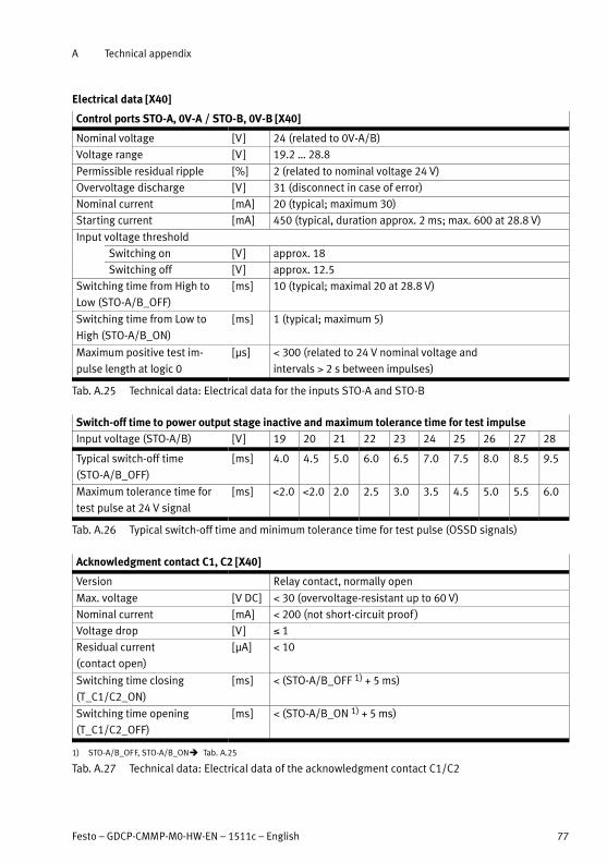
A Technical appendix
Festo – GDCP-CMMP-M0-HW-EN – 1511c – English 77
Electrical data [X40]
Control ports STO-A, 0V-A / STO-B, 0V-B [X40]
Nominal voltage [V] 24 (related to 0V-A/B)
Voltage range [V] 19.2 … 28.8
Permissible residual ripple [%] 2 (related to nominal voltage 24 V)
Overvoltage discharge [V] 31 (disconnect in case of error)
Nominal current [mA] 20 (typical; maximum 30)
Starting current [mA] 450 (typical, duration approx. 2 ms; max. 600 at 28.8 V)
Input voltage threshold
Switching on [V] approx. 18
Switching off [V] approx. 12.5
Switching time from High to
Low (STO-A/B_OFF)
[ms] 10 (typical; maximal 20 at 28.8 V)
Switching time from Low to
High (STO-A/B_ON)
[ms] 1 (typical; maximum 5)
Maximum positive test im
pulse length at logic 0
[μs] 300 (related to 24 V nominal voltage and
intervals 2 s between impulses)
Tab. A.25 Technical data: Electrical data for the inputs STO-A and STO-B
Switch-off time to power output stage inactive and maximum tolerance time for test impulse
Input voltage (STO-A/B) [V] 19 20 21 22 23 24 25 26 27 28
Typical switch-off time
(STO-A/B_OFF)
[ms] 4.0 4.5 5.0 6.0 6.5 7.0 7.5 8.0 8.5 9.5
Maximum tolerance time for
test pulse at 24 V signal
[ms] 2.0 2.0 2.0 2.5 3.0 3.5 4.5 5.0 5.5 6.0
Tab. A.26 Typical switch-off time and minimum tolerance time for test pulse (OSSD signals)
Acknowledgment contact C1, C2 [X40]
Version Relay contact, normally open
Max. voltage [V DC] 30 (overvoltage-resistant up to 60 V)
Nominal current [mA] 200 (not short-circuit proof )
Voltage drop [V] 1
Residual current
(contact open)
[μA] 10
Switching time closing
(T_C1/C2_ON)
[ms] (STO-A/B_OFF 1) + 5 ms)
Switching time opening
(T_C1/C2_OFF)
[ms] (STO-A/B_ON 1) + 5 ms)
1) STO-A/B_OFF, STO-A/B_ON� Tab. A.25
Tab. A.27 Technical data: Electrical data of the acknowledgment contact C1/C2

A Technical appendix
78 Festo – GDCP-CMMP-M0-HW-EN – 1511c – English
Auxiliary supply 24 V, 0 V [X40] – output
Version Logic supply voltage routed out of the motor controller (fed
in at [X9], not additionally filtered or stabilised). Reverse-po
larity protected, overvoltage-proof up to 60 V DC.
Nominal voltage DC [V] 24
Nominal current [mA] 100 (short circuit proof, max 300 mA)
Voltage drop [V] 1 (for nominal current)
Tab. A.28 Technical data: Electrical data of the auxiliary supply output
Galvanic isolation
Galvanically isolated potential areas STO-A / 0V-A
STO-B / 0V-B
C1 / C2
24 V / 0 V (logic supply of the motor controller)
Tab. A.29 Technical data: Galvanic isolation [X40]
Cabling
Max. cable length [m] 30
Screening When wiring outside the control cabinet, use screened
cable. Guide screening into the control cabinet / attach to
the side of the control cabinet.
Cable cross section (flexible conductors, wire end sleeve with insulating collar)
One conductor [mm²] 0.25 … 0.5
Two conductors [mm²] 2 x 0.25 (with twin wire end sleeves)
Tightening torque M2 [Nm] 0.22 … 0.25
Tab. A.30 Technical data: Cabling at [X40]

A Technical appendix
Festo – GDCP-CMMP-M0-HW-EN – 1511c – English 79
A.2 Supported encoders
Resolver
Type Protocol Interface Comment
Standard – [X2A] Transmission ratio 0.5 ±10 %,
excitation voltage 7 Vrms
Tab. A.31 Supported resolvers
Digital encoders
Type Protocol Interface Comment
Yaskawa
∑-encoder
Yaskawa-
OEM protocol
[X2B] Yaskawa Sigma-1 Type A
Tab. A.32 Supported digital encoders
Analogue encoders
Type Protocol Interface Comment
ROD 400
ERO 1200, 1300,
1400
ERN 100, 400,
1100, 1300
– [X2B] Heidenhain, encoder with zero im
pulse and reference signal
Tab. A.33 Supported analogue encoders
EnDat encoders
Type Protocol Interface Comment
ROC 400
ECI 1100, 1300
ECN 100, 400,
1100, 1300
EnDat 2.1 (01/21)
EnDat 2.2 (22)
[X2B] Heidenhain single-turn absolute en
coder with/without analogue signal
ROQ 400
EQI 1100, 1300
EQN 100, 400,
1100, 1300
EnDat 2.1 (01/21)
EnDat 2.2 (22)
[X2B] Heidenhain multi-turn absolute en
coder with/without analogue signal
LC 100, 400 EnDat 2.1 (01)
EnDat 2.2 (22)
[X2B] Heidenhain absolute length measure
ment equipment
Tab. A.34 Supported EnDat encoders

A Technical appendix
80 Festo – GDCP-CMMP-M0-HW-EN – 1511c – English
HIPERFACE encoders
Type Protocol Interface Comment
SCS60, 70
SCM60, 70
HIPERFACE [X2B] Stegmann single-/multi-turn encoder
with analogue incremental signal
sine/cosine periods 512. Max. revolu
tions multi-turn: ±2048 R
SRS 50, 60, 64
SCKxx
SRM 50, 60, 64
SCLxx
HIPERFACE [X2B] Stegmann single-/multi-turn encoder
with analogue incremental signals.
Sine/cosine periods 1024. Max. re
volutions multi-turn: ±2048 R
SKS36
SKM36
HIPERFACE [X2B] Stegmann single-/multi-turn encoder
with analogue incremental signals.
Sine/cosine periods 128. Max. re
volutions multi-turn: ±2048 R
SEK37, 52
SEL37, 52
HIPERFACE [X2B] Stegmann single-/multi-turn encoder
with analogue incremental signals.
Sine/cosine periods 16. Max. revolu
tions multi-turn: ±2048 R
L230 HIPERFACE [X2B] Stegmann absolute linear encoder
with analogue incremental signal
measurement step: 156.25 μm.
Measuring length max. approx. 40 m.
Tab. A.35 Supported HIPERFACE encoders
BiSS encoder
Type Protocol Interface Comment
ME 20.20-0.40 BiSS [X2B] ELGO magnetic incremental linear en
coder (use e.g. for ELGL-LAS...)
Tab. A.36 Supported BiSS encoders

B Diagnostic messages
Festo – GDCP-CMMP-M0-HW-EN – 1511c – English 81
B Diagnostic messages
If an error occurs, the motor controller CMMP-AS-...-M0 shows a diagnostic message cyclically in the 7-seg
ment display. An error message consists of an E (for Error), a main index and sub-index, e.g.: - E 0 1 0 -.
Warnings have the same number as an error message. In contrast to error messages, however, warn
ings are preceded and followed by hyphens, e.g. - 1 7 0 -.
B.1 Explanations of the diagnostic messages
The following table summarises the significance of the diagnostic messages and the actions to be
taken in response to them:
Terms Meaning
No. Main index (error group) and sub-index of the diagnostic message.
Shown in the display, in FCT or diagnostic memory via FHPP.
Code The Code column includes the error code (Hex) via CiA 301.
Message Message that is displayed in the FCT.
Cause Possible causes for the message.
Action Action by the user.
Reaction The Reaction column includes the error response (default setting, partially
configurable):
– PS off (switch off output stage),
– MCStop (fast stop with maximum current),
– QStop (fast stop with parameterised ramp),
– Warn (warning),
– Ignore (No message, only entry in diagnostic memory),
– NoLog (No message and no entry in diagnostic memory).
Tab. B.1 Explanations of the diagnostic messages
A complete list of the diagnostic messages corresponding to the firmware statuses at the time of print
ing of this document can be found in section B.2.

B Diagnostic messages
82 Festo – GDCP-CMMP-M0-HW-EN – 1511c – English
B.2 Diagnostic messages with instructions for fault clearance
Error group 0 Information
No. Code Message Reaction
0-0 - Invalid error Ignore
Cause Information: An invalid error entry (corrupted) was found in the
diagnostic memory marked with this error number.
The system time entry is set to 0.
Action –
0-1 - Invalid error detected and corrected Ignore
Cause Information: An invalid error entry (corrupted) was found in the
diagnostic memory and corrected. The additional information con
tains the original error number.
The system time entry includes the address of the corrupted error
number.
Action –
0-2 - Error cleared Ignore
Cause Information: Active errors were acknowledged.
Action –
0-7 - Subsequent entry Ignore
Cause Information: � Diagnostic memory entry.
Action –
0-8 - Controller switched on Ignore
Cause Information: � Diagnostic memory entry.
Action –
0-22 - Default parameter record loaded Ignore
Cause Information: � Diagnostic memory entry.
Action –
Error group 1 Stack overflow
No. Code Message Reaction
1-0 6180h Stack overflow PSoff
Cause – Incorrect firmware?
– Sporadic high processor load due to cycle time being too short
and specific processor-intensive processes (save parameter set
etc.).
Action � Load an approved firmware.
� Reduce the processor load.
� Contact Technical Support.
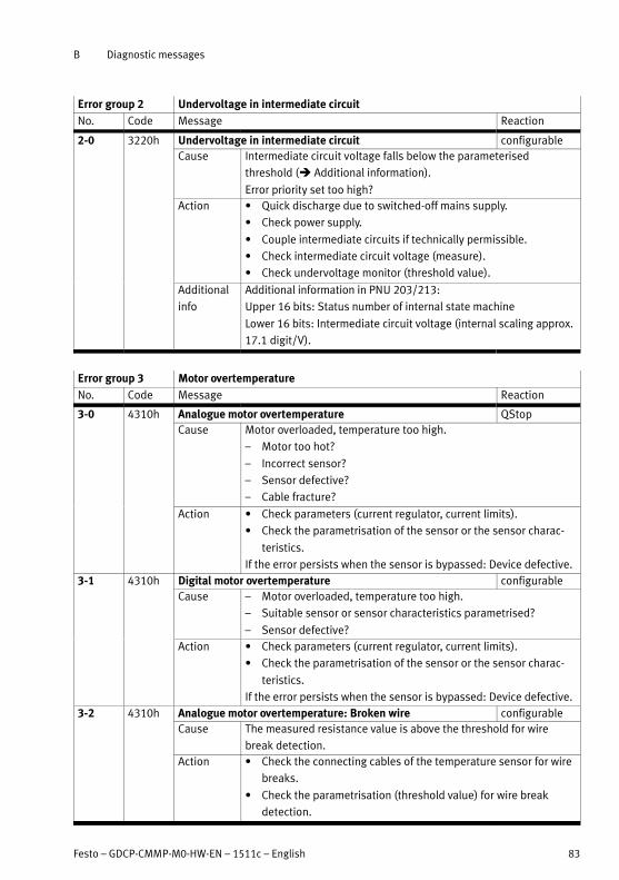
B Diagnostic messages
Festo – GDCP-CMMP-M0-HW-EN – 1511c – English 83
Error group 2 Undervoltage in intermediate circuit
No. Code Message Reaction
2-0 3220h Undervoltage in intermediate circuit configurable
Cause Intermediate circuit voltage falls below the parameterised
threshold (� Additional information).
Error priority set too high?
Action � Quick discharge due to switched-off mains supply.
� Check power supply.
� Couple intermediate circuits if technically permissible.
� Check intermediate circuit voltage (measure).
� Check undervoltage monitor (threshold value).
Additional
info
Additional information in PNU 203/213:
Upper 16 bits: Status number of internal state machine
Lower 16 bits: Intermediate circuit voltage (internal scaling approx.
17.1 digit/V).
Error group 3 Motor overtemperature
No. Code Message Reaction
3-0 4310h Analogue motor overtemperature QStop
Cause Motor overloaded, temperature too high.
– Motor too hot?
– Incorrect sensor?
– Sensor defective?
– Cable fracture?
Action � Check parameters (current regulator, current limits).
� Check the parametrisation of the sensor or the sensor charac
teristics.
If the error persists when the sensor is bypassed: Device defective.
3-1 4310h Digital motor overtemperature configurable
Cause – Motor overloaded, temperature too high.
– Suitable sensor or sensor characteristics parametrised?
– Sensor defective?
Action � Check parameters (current regulator, current limits).
� Check the parametrisation of the sensor or the sensor charac
teristics.
If the error persists when the sensor is bypassed: Device defective.
3-2 4310h Analogue motor overtemperature: Broken wire configurable
Cause The measured resistance value is above the threshold for wire
break detection.
Action � Check the connecting cables of the temperature sensor for wire
breaks.
� Check the parametrisation (threshold value) for wire break
detection.
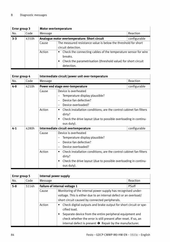
B Diagnostic messages
84 Festo – GDCP-CMMP-M0-HW-EN – 1511c – English
Error group 3 Motor overtemperature
No. ReactionMessageCode
3-3 4310h Analogue motor overtemperature: Short circuit configurable
Cause The measured resistance value is below the threshold for short
circuit detection.
Action � Check the connecting cables of the temperature sensor for wire
breaks.
� Check the parametrisation (threshold value) for short circuit
detection.
Error group 4 Intermediate circuit/power unit over-temperature
No. Code Message Reaction
4-0 4210h Power end stage over-temperature configurable
Cause Device is overheated
– Temperature display plausible?
– Device fan defective?
– Device overloaded?
Action � Check installation conditions; are the control cabinet fan filters
dirty?
� Check the drive layout (due to possible overloading in continu
ous duty).
4-1 4280h Intermediate circuit overtemperature configurable
Cause Device is overheated
– Temperature display plausible?
– Device fan defective?
– Device overloaded?
Action � Check installation conditions; are the control cabinet fan filters
dirty?
� Check the drive layout (due to possible overloading in continu
ous duty).
Error group 5 Internal power supply
No. Code Message Reaction
5-0 5114h Failure of internal voltage 1 PSoff
Cause Monitoring of the internal power supply has recognised under
voltage. This is either due to an internal defect or an overload/
short circuit caused by connected peripherals.
Action � Check digital outputs and brake output for short circuit or spe
cified load.
� Separate device from the entire peripheral equipment and
check whether the error is still present after reset. If so, an
internal defect is present � Repair by the manufacturer.

B Diagnostic messages
Festo – GDCP-CMMP-M0-HW-EN – 1511c – English 85
Error group 5 Internal power supply
No. ReactionMessageCode
5-1 5115h Failure of internal voltage 2 PSoff
Cause Monitoring of the internal power supply has recognised under
voltage. This is either due to an internal defect or an overload/
short circuit caused by connected peripherals.
Action � Check digital outputs and brake output for short circuit or spe
cified load.
� Separate device from the entire peripheral equipment and
check whether the error is still present after reset. If so, an
internal defect is present � Repair by the manufacturer.
5-2 5116h Failure of driver supply PSoff
Cause Monitoring of the internal power supply has recognised under
voltage. This is either due to an internal defect or an overload/
short circuit caused by connected peripherals.
Action � Check digital outputs and brake output for short circuit or spe
cified load.
� Separate device from the entire peripheral equipment and
check whether the error is still present after reset. If so, an
internal defect is present � Repair by the manufacturer.
5-3 5410h Undervoltage of digital I/O PSoff
Cause Overloading of the I/Os?
Defective peripheral device?
Action � Check connected peripherals for short circuit / rated loads.
� Check connection of the brake (connected incorrectly?).
5-4 5410h Over-current of digital I/O PSoff
Cause Overloading of the I/Os?
Defective peripheral device?
Action � Check connected peripherals for short circuit / rated loads.
� Check connection of the brake (connected incorrectly?).
5-5 - Voltage failure of module in Ext1/Ext2 PSoff
Cause Defect on the plugged-in interface.
Action � Interface replacement � Repair by the manufacturer.
5-6 - X10, X11 and RS232 supply voltage failure PSoff
Cause Overloading through connected peripherals.
Action � Check pin allocation of the connected peripherals.
� Short circuit?
5-7 - Safety module internal voltage failure PSoff
Cause Defect on the safety module.
Action � Internal defect � Repair by the manufacturer.
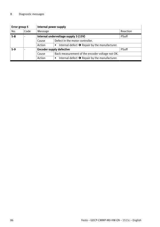
B Diagnostic messages
86 Festo – GDCP-CMMP-M0-HW-EN – 1511c – English
Error group 5 Internal power supply
No. ReactionMessageCode
5-8 - Internal undervoltage supply 3 (15V) PSoff
Cause Defect in the motor controller.
Action � Internal defect � Repair by the manufacturer.
5-9 - Encoder supply defective PSoff
Cause Back measurement of the encoder voltage not OK.
Action � Internal defect � Repair by the manufacturer.
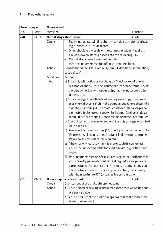
B Diagnostic messages
Festo – GDCP-CMMP-M0-HW-EN – 1511c – English 87
Error group 6 Over-current
No. Code Message Reaction
6-0 2320h Output stage short circuit PSoff
Cause – Faulty motor, e.g. winding short circuit due to motor overheat
ing or short to PE inside motor.
– Short circuit in the cable or the connecting plugs, i.e. short
circuit between motor phases or to the screening/PE.
– Output stage defective (short circuit).
– Incorrect parameterisation of the current regulator.
Action Dependent on the status of the system � Additional information,
cases a) to f ).
Additional
info
Actions:
a) Error only with active brake chopper: Check external braking
resistor for short circuit or insufficient resistance value. Check
circuitry of the brake chopper output at the motor controller
(bridge, etc.).
b) Error message immediately when the power supply is connec
ted: Internal short circuit in the output stage (short circuit of a
complete half-bridge). The motor controller can no longer be
connected to the power supply; the internal (and possibly ex
ternal) fuses are tripped. Repair by the manufacturer required.
c) Short circuit error message not until the output stage or control
ler is enabled.
d) Disconnection of motor plug [X6] directly at the motor controller.
If the error still occurs, there is a fault in the motor controller.
Repair by the manufacturer required.
e) If the error only occurs when the motor cable is connected:
Check the motor and cable for short circuits, e.g. with a multi
meter.
f ) Check parameterisation of the current regulator. Oscillations in
an incorrectly parameterised current regulator can generate
currents up to the short circuit threshold, usually clearly aud
ible as a high-frequency whistling. Verification, if necessary,
with the trace in the FCT (actual active current value).
6-1 2320h Brake chopper over-current PSoff
Cause Over-current at the brake chopper output.
Action � Check external braking resistor for short circuit or insufficient
resistance value.
� Check circuitry of the brake chopper output at the motor con
troller (bridge, etc.).

B Diagnostic messages
88 Festo – GDCP-CMMP-M0-HW-EN – 1511c – English
Error group 7 Overvoltage in intermediate circuit
No. Code Message Reaction
7-0 3210h Overvoltage in intermediate circuit PSoff
Cause Braking resistor is overloaded; too much braking energy, which
cannot be dissipated quickly enough.
– Resistor capacity is incorrect?
– Resistor not connected correctly?
– Check design (application).
Action � Check the design of the braking resistor; resistance value may
be too great.
� Check the connection to the braking resistor (internal/external).
Error group 8 Angle encoder
No. Code Message Reaction
8-0 7380h Resolver angular encoder error configurable
Cause Resolver signal amplitude is faulty.
Action Step-by-step procedure � Additional information, cases a) to c).
Additional
info
a) If possible, test with a different (error-free) resolver (replace the
connecting cable, too). If the error still occurs, there is a fault in
the motor controller. Repair by the manufacturer required.
b) If the error occurs only with a special resolver and its connecting
cable: Check resolver signals (carrier and SIN/COS signal), see
specification. If the signals do not comply with the signal spe
cifications, replace the resolver.
c) If the error recurs sporadically, check the screen bonding or
check whether the resolver simply has an insufficient transmis
sion ratio (standard resolver: A = 0.5).

B Diagnostic messages
Festo – GDCP-CMMP-M0-HW-EN – 1511c – English 89
Error group 8 Angle encoder
No. ReactionMessageCode
8-1 - Sense of rotation of the serial and incremental position evalu
ation is not identical
configurable
Cause Only encoders with serial position transmission combined with an
analogue SIN/COS signal track: The directions of rotation for posi
tion determination in the encoder and for incremental evaluation of
the analogue track system in the motor controller are the wrong
way round � Additional information.
Action Swap the following signals on the [X2B] angle encoder interface
(the wires in the connecting plug must be changed around), ob
serving the technical data for the angle encoder where applicable:
– Swap SIN/COS track.
– Swap the SIN+/SIN- or COS+/COS- signals, as applicable.
Additional
info
The encoder counts internally, for example positively in clockwise
rotation, while the incremental evaluation counts in negative direc
tion with the same mechanical rotation. The interchange of the
direction of rotation is detected mechanically at the first movement
of over 30°, and the error is triggered.
8-2 7382h Error in incremental encoder tracking signals Z0 configurable
Cause Signal amplitude of the Z0 track at [X2B] is faulty.
– Angle encoder connected?
– Angle encoder cable defective?
– Angle encoder defective?
Action Check configuration of angle encoder interface:
a) Z0 evaluation activated, but no track signals connected or
present � Additional information.
b) Encoder signals faulty?
c) Test with another encoder.
� Tab. B.2, page 120.
Additional
info
For example, EnDat 2.2 or EnDat 2.1 without analogue track.
Heidenhain encoder: Order codes EnDat 22 and EnDat 21. With
these encoders there are no incremental signals, even when the
cables are connected.

B Diagnostic messages
90 Festo – GDCP-CMMP-M0-HW-EN – 1511c – English
Error group 8 Angle encoder
No. ReactionMessageCode
8-3 7383h Error in incremental encoder tracking signals Z1 configurable
Cause Signal amplitude of the Z1 track at X2B is faulty.
– Angle encoder connected?
– Angle encoder cable defective?
– Angle encoder defective?
Action Check configuration of angle encoder interface:
a) Z1 evaluation activated but not connected.
b) Encoder signals faulty?
c) Test with another encoder.
� Tab. B.2, page 120.
8-4 7384h Digital incremental encoder track signals error [X2B] configurable
Cause Faulty A, B, or N track signals at [X2B].
– Angle encoder connected?
– Angle encoder cable defective?
– Angle encoder defective?
Action Check the configuration of the angle encoder interface.
b) Encoder signals faulty?
b) Test with another encoder.
� Tab. B.2, page 120.
8-5 7385h Error in incremental encoder of Hall-effect encoder signals configurable
Cause Hall encoder signals of a dig. Inc. at [X2B] faulty.
– Angle encoder connected?
– Angle encoder cable defective?
– Angle encoder defective?
Action Check the configuration of the angle encoder interface.
b) Encoder signals faulty?
b) Test with another encoder.
� Tab. B.2, page 120.

B Diagnostic messages
Festo – GDCP-CMMP-M0-HW-EN – 1511c – English 91
Error group 8 Angle encoder
No. ReactionMessageCode
8-6 7386h Angle encoder communication fault configurable
Cause Communication to serial angle encoders is disrupted
(EnDat encoders, HIPERFACE encoders, BiSS encoders).
– Angle encoder connected?
– Angle encoder cable defective?
– Angle encoder defective?
Action Check configuration of the angle encoder interface, procedure
corresponding to a) to c):
a) Serial encoder parameterised but not connected? Incorrect
serial protocol selected?
b) Encoder signals faulty?
c) Test with another encoder.
� Tab. B.2, page 120.
8-7 7387h Signal amplitude of incremental tracks faulty [X10] configurable
Cause Faulty A, B, or N track signals at [X10].
– Angle encoder connected?
– Angle encoder cable defective?
– Angle encoder defective?
Action Check the configuration of the angle encoder interface.
b) Encoder signals faulty?
b) Test with another encoder.
� Tab. B.2, page 120.
8-8 7388h Internal angle encoder error configurable
Cause Internal monitoring of the angle encoder [X2B] has detected an
error and forwarded it via serial communication to the controller.
– Declining illumination intensity with visual encoders?
– Excess rotational speed?
– Angle encoder defective?
Action If the error occurs repeatedly, the encoder is defective.
� Replace encoder.

B Diagnostic messages
92 Festo – GDCP-CMMP-M0-HW-EN – 1511c – English
Error group 8 Angle encoder
No. ReactionMessageCode
8-9 7389h Angle encoder at [X2B] is not supported configurable
Cause Angle encoder type read at [X2B], which is not supported or cannot
be used in the desired operating mode.
– Incorrect or inappropriate protocol type selected?
– Firmware does not support the connected encoder model?
Action Depending on the additional information of the error message
� Additional information:
� Load appropriate firmware.
� Check/correct the configuration for encoder evaluation.
� Connect an appropriate encoder type.
Additional
info
Additional info (PNU 203/213):
0001: HIPERFACE: Encoder type is not supported by the firmware
� Connect another encoder type or load more recent firmware,
if applicable.
0002: EnDat: The address space in which the encoder parameter
would have to lie does not exist with the connected EnDat en
coder � Check the encoder type.
0003: EnDat: Encoder type is not supported by the firmware
� Connect another encoder type or load more recent firmware,
if applicable.
0004: EnDat: Encoder rating plate cannot be read from the connec
ted encoder. � Replace encoder or load more recent firmware,
if applicable.
0005: EnDat: EnDat 2.2 interface parameterised, but connected
encoder supports only EnDat 2.1. � Change encoder type or
reparameterise to EnDat 2.1.
0006: EnDat: EnDat2.1 interface with analogue track evaluation
parameterised, but according to rating plate the connected
encoder does not support track signals. � Replace encoder or
switch off Z0 track signal evaluation.
0007: Code length measuring system with EnDat2.1 connected,
but parameterised as a purely serial encoder. Purely serial eval
uation is not possible due to the long response times of this
encoder system. Encoder must be operated with analogue
tracking signal evaluation � Connect to analogue Z0 tracking
signal evaluation.
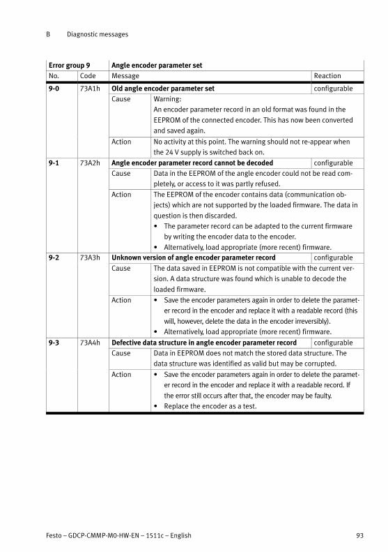
B Diagnostic messages
Festo – GDCP-CMMP-M0-HW-EN – 1511c – English 93
Error group 9 Angle encoder parameter set
No. Code Message Reaction
9-0 73A1h Old angle encoder parameter set configurable
Cause Warning:
An encoder parameter record in an old format was found in the
EEPROM of the connected encoder. This has now been converted
and saved again.
Action No activity at this point. The warning should not re-appear when
the 24 V supply is switched back on.
9-1 73A2h Angle encoder parameter record cannot be decoded configurable
Cause Data in the EEPROM of the angle encoder could not be read com
pletely, or access to it was partly refused.
Action The EEPROM of the encoder contains data (communication ob
jects) which are not supported by the loaded firmware. The data in
question is then discarded.
� The parameter record can be adapted to the current firmware
by writing the encoder data to the encoder.
� Alternatively, load appropriate (more recent) firmware.
9-2 73A3h Unknown version of angle encoder parameter record configurable
Cause The data saved in EEPROM is not compatible with the current ver
sion. A data structure was found which is unable to decode the
loaded firmware.
Action � Save the encoder parameters again in order to delete the paramet
er record in the encoder and replace it with a readable record (this
will, however, delete the data in the encoder irreversibly).
� Alternatively, load appropriate (more recent) firmware.
9-3 73A4h Defective data structure in angle encoder parameter record configurable
Cause Data in EEPROM does not match the stored data structure. The
data structure was identified as valid but may be corrupted.
Action � Save the encoder parameters again in order to delete the paramet
er record in the encoder and replace it with a readable record. If
the error still occurs after that, the encoder may be faulty.
� Replace the encoder as a test.

B Diagnostic messages
94 Festo – GDCP-CMMP-M0-HW-EN – 1511c – English
Error group 9 Angle encoder parameter set
No. ReactionMessageCode
9-4 - EEPROM data: Erroneous custom specific configuration configurable
Cause Only with specialised motors:
The plausibility check returns an error, e.g. because the motor was
repaired or exchanged.
Action � If motor repaired: Carry out homing again and save in the angle
encoder, after that (!) save in the motor controller.
� If motor exchanged: Parameterise the controller again, then
carry out homing again and save in the angle encoder, after that
(!) save in the motor controller.
9-5 - Read/write error EEPROM parameter record configurable
Cause When reading or writing data to the internal sensor parameter
record, an error occurred.
Action Occurs on Hiperface sensors: a data field in the sensor EEPROM is
not suitable for being interrogated by the firmware or for unknown
reasons, no data can be written to the sensor.
� Send motor to the manufacturer for inspection.
9-7 73A5h Write-protected EEPROM angle encoder configurable
Cause Data cannot be saved in the EEPROM of the angle encoder.
Occurs with Hiperface encoders.
Action A data field in the encoder EEPROM is read-only (e.g. after opera
tion on a motor controller of another manufacturer). No solution
possible, encoder memory must be unlocked with a corresponding
parameterisation tool (from manufacturer).
9-9 73A6h Angle encoder’s EEPROM too small configurable
Cause It is not possible to save all the data in the EEPROM of the angle
encoder.
Action � Reduce the number of data records to be saved. Please read
the documentation or contact Technical Support.
Error group 10 Velocity Violation
No. Code Message Reaction
10-0 - Velocity Violation configurable
Cause – Motor racing (“spinning”) because the commutation angle off
set is incorrect.
– Motor is parametrised correctly but the limit for spinning pro
tection is set too low.
Action � Check the commutation angle offset.
� Check the limit value setting in the parameters.

B Diagnostic messages
Festo – GDCP-CMMP-M0-HW-EN – 1511c – English 95
Error group 11 Homing
No. Code Message Reaction
11-0 8A80h Error when starting the homing run configurable
Cause Controller enable missing.
Action Homing can only be started when closed-loop controller enable is
active.
� Check the condition or sequence.
11-1 8A81h Error during homing configurable
Cause Homing was interrupted, e.g. by:
– Withdrawal of controller enable.
– Reference switch is beyond the limit switch.
– External stop signal (a phase was aborted during homing).
Action � Check homing sequence.
� Check arrangement of the switches.
� If applicable, lock the stop input during homing if it is not desired.
11-2 8A82h Homing: No valid index pulse configurable
Cause Required zero impulse during homing missing.
Action � Check the zero impulse signal.
� Check the angle encoder settings.
11-3 8A83h Homing: Timeout configurable
Cause The parameterised maximum time for the homing run was ex
ceeded before homing was completed.
Action � Check the time setting in the parameters.
11-4 8A84h Homing: Incorrect limit switch configurable
Cause – Relevant limit switch not connected.
– Limit switches swapped?
– No reference switch found between the two limit switches.
– Reference switch is at the limit switch.
– Current position with zero impulse method: Limit switch active
in the area of the zero impulse (not permissible).
– Both limit switches active at the same time.
Action � Check whether the limit switches are connected in the correct
direction of travel or whether the limit switches have an effect
on the intended inputs.
� Reference switch connected?
� Check configuration of the reference switches.
� Move limit switch so that it is not in the zero pulse area.
� Check limit switch parametrisation (N/C contact/N/O contact).

B Diagnostic messages
96 Festo – GDCP-CMMP-M0-HW-EN – 1511c – English
Error group 11 Homing
No. ReactionMessageCode
11-5 8A85h Homing: I²t / following error configurable
Cause – Acceleration ramps inappropriately parametrised.
– Reversing due to premature triggering of following error; check
parametrisation of following error.
– No reference switch reached between the end stops.
– Zero pulse method: End stop reached (here not permissible).
Action � Parameterise the acceleration ramps so they are flatter.
� Check connection of a reference switch.
� Method appropriate for the application?
11-6 8A86h Homing: End of search path configurable
Cause The maximum permissible path for the homing run has been trav
elled without reaching the point of reference or the homing run
destination.
Action Fault in switch detection.
� Switch for homing is defective?
11-7 - Homing: Error in encoder difference monitoring configurable
Cause Deviation between the actual position value and commutation
position is too great. External angle encoder not connected or
faulty?
Action � Deviation fluctuates, e.g. due to gear backlash; cut-off
threshold may need to be increased.
� Check connection of the actual value encoder.
Error group 12 CAN communication
No. Code Message Reaction
12-0 8180h CAN: Double node number configurable
Cause Node number assigned twice.
Action � Check the configuration of the stations on the CAN bus.
12-1 8120h CAN: Communication error, bus OFF configurable
Cause The CAN chip has switched off communication due to communica
tion errors (BUS OFF).
Action � Check wiring: Cable specification adhered to, broken cable,
maximum cable length exceeded, correct terminating resistors,
cable screening earthed, all signals terminated?
� Replace device on a test basis. If a different device works
without errors with the same cabling, send the device to the
manufacturer for inspection.

B Diagnostic messages
Festo – GDCP-CMMP-M0-HW-EN – 1511c – English 97
Error group 12 CAN communication
No. ReactionMessageCode
12-2 8181h CAN: Communication error during transmission configurable
Cause The signals are corrupted when transmitting messages.
Device boot up is so fast that no other nodes on the bus have yet
been detected when the boot-up message is sent.
Action � Check wiring: Cable specification adhered to, broken cable,
maximum cable length exceeded, correct terminating resistors,
cable screening earthed, all signals terminated?
� Replace device on a test basis. If a different device works
without errors with the same cabling, send the device to the
manufacturer for inspection.
12-3 8182h CAN: Communication error during reception configurable
Cause The signals are corrupted when receiving messages.
Action � Check wiring: Cable specification adhered to, broken cable,
maximum cable length exceeded, correct terminating resistors,
cable screening earthed, all signals terminated?
� Replace device on a test basis. If a different device works
without errors with the same cabling, send the device to the
manufacturer for inspection.
12-4 - Node guarding telegram not received configurable
Cause Node guarding telegram not received within the parametrised
time. Signals corrupted?
Action � Compare cycle time of the remote frames with that of the
controller.
� Check: Failure of the controller?
12-5 - CAN: RPDO too short configurable
Cause A received RPDO does not contain the parameterised number of
bytes.
Action The number of parametrised bytes does not match the number of
bytes received.
� Check the parametrisation and correct.
12-9 - CAN: Protocol error configurable
Cause Faulty bus protocol.
Action � Check the parametrisation of the selected CAN bus protocol.
Error group 13 CAN bus timeout
No. Code Message Reaction
13-0 - CAN: Timeout configurable
Cause Error message from manufacturer-specific protocol.
Action � Check the CAN parameters.

B Diagnostic messages
98 Festo – GDCP-CMMP-M0-HW-EN – 1511c – English
Error group 14 Identification
No. Code Message Reaction
14-0 - Automatic identification of the current regulator: Insufficient
intermediate circuit voltage
PSoff
Cause Current regulator parameters cannot be determined (insufficient
supply).
Action The available intermediate circuit voltage is too low to carry out
the measurement.
14-1 - Automatic identification of the current regulator: Measure
ment cycle insufficient
PSoff
Cause Too few or too many measurement cycles required for the connec
ted motor.
Action Automatic determination of parameters has supplied a time con
stant outside the parameterisable value range.
� The parameters must be manually optimised.
14-2 - Automatic identification of the current regulator: Output stage
enable could not be issued
PSoff
Cause The output stage has not been enabled.
Action � Check the connection of DIN4.
14-3 - Automatic identification of the current regulator: Output stage
was switched off prematurely
PSoff
Cause Output stage enable was switched off while identification was in
progress.
Action � Check the sequence control.
14-5 - Automatic identification of the angle encoder: Zero impulse
could not be found
PSoff
Cause The zero impulse could not be found following execution of the
maximum permissible number of electrical revolutions.
Action � Check the index pulse signal.
� Angle encoder parametrised correctly?
14-6 - Automatic identification of the angle encoder: Hall signals
invalid
PSoff
Cause Hall signals faulty or invalid.
The pulse train and/or segmenting of the Hall signals is i
nappropriate.
Action � Check connection.
� Refer to the technical data to check whether the encoder
shows three Hall signals with 1205 or 605 segments; if neces
sary, contact Technical Support.

B Diagnostic messages
Festo – GDCP-CMMP-M0-HW-EN – 1511c – English 99
Error group 14 Identification
No. ReactionMessageCode
14-7 - Automatic identification of the angle encoder: Identification
not possible
PSoff
Cause Angle encoder at a standstill.
Action � Ensure sufficient intermediate circuit voltage.
� Encoder cable connected to the right motor?
� Motor blocked, e.g. holding brake does not release?
14-8 - Automatic identification of the angle encoder: Invalid number
of pole pairs
PSoff
Cause The calculated number of pole pairs lies outside the parameteris
able range.
Action � Compare result with the technical data specifications for the
motor.
� Check the parametrised number of lines.
Error group 15 Invalid operation
No. Code Message Reaction
15-0 6185h Division by zero PSoff
Cause Internal firmware error. Division by 0 when using the math library.
Action � Load factory settings.
� Check the firmware to make sure that released firmware has
been loaded.
15-1 6186h Mathematical overflow during division PSoff
Cause Internal firmware error. Overflow when using the math library.
Action � Load factory settings.
� Check the firmware to make sure that released firmware has
been loaded.
15-2 - Mathematical underflow PSoff
Cause Internal firmware error. Internal correction factors could not be
calculated.
Action � Check the setting of the factor group for extreme values and
change if necessary.
Error group 16 Internal error
No. Code Message Reaction
16-0 6181h Error in program execution PSoff
Cause Internal firmware error. Error during program execution. Illegal CPU
command found in the program sequence.
Action � In case of repetition, load firmware again. If the error occurs
repeatedly, the hardware is defective.

B Diagnostic messages
100 Festo – GDCP-CMMP-M0-HW-EN – 1511c – English
Error group 16 Internal error
No. ReactionMessageCode
16-1 6182h Illegal interrupt PSoff
Cause Error during program execution. An unused IRQ vector was used by
the CPU.
Action � In case of repetition, load firmware again. If the error occurs
repeatedly, the hardware is defective.
16-2 6187h Initialisation error PSoff
Cause Error in initialising the default parameters.
Action � In case of repetition, load firmware again. If the error occurs
repeatedly, the hardware is defective.
16-3 6183h Unexpected state PSoff
Cause Error during periphery access within the CPU or error in the pro
gram sequence (illegal branching in case structures).
Action � In case of repetition, load firmware again. If the error occurs
repeatedly, the hardware is defective.
Error group 17 Contouring error limit value exceeded
No. Code Message Reaction
17-0 8611h Contouring error limit value exceeded configurable
Cause Comparison threshold for the limit value of the following error
exceeded.
Action � Enlarge error window.
� Parameterise acceleration to be less.
� Motor overloaded (current limiter from the I²t monitoring active?).
17-1 8611h Encoder difference monitoring configurable
Cause Deviation between the actual position value and commutation
position is too great.
External angle encoder not connected or faulty?
Action � Deviation fluctuates, e.g. due to gear backlash; cut-off
threshold may need to be increased.
� Check connection of the actual value encoder.
Error group 18 Temperature warning threshold
No. Code Message Reaction
18-0 - Analogue motor temperature configurable
Cause Motor temperature (analogue) greater than 5° below T_max.
Action � Check parametrisation of current regulator and/or speed
regulator.
� Motor permanently overloaded?

B Diagnostic messages
Festo – GDCP-CMMP-M0-HW-EN – 1511c – English 101
Error group 21 Current measurement
No. Code Message Reaction
21-0 5280h Error 1 current measurement U PSoff
Cause Offset for current measurement 1 phase U is too great. The control
ler carries out offset compensation of the current measurement
every time its controller enable is issued. Tolerances that are too
large result in an error.
Action If the error occurs repeatedly, the hardware is defective.
21-1 5281h Error 1 current measurement V PSoff
Cause Offset for current measurement 1 phase V is too great.
Action If the error occurs repeatedly, the hardware is defective.
21-2 5282h Error 2 current measurement U PSoff
Cause Offset for current measurement 2 phase U is too great.
Action If the error occurs repeatedly, the hardware is defective.
21-3 5283h Error 2 current measurement V PSoff
Cause Offset for current measurement 2 phase V is too great.
Action If the error occurs repeatedly, the hardware is defective.
Error group 23 Saving/restoring of the actual position
No. Code Message Reaction
23-0 - Actual position: no valid entry present. configurable
Cause – No entry saved after activation.
– No position saved because drive was not referenced.
– Hardware reset occurred prematurely.
Action Comply with activation sequence:
1. Enable function.
2. Save and restart.
3. Carry out a reference run.
23-1 - Actual position: Invalid checksum configurable
Cause It was not possible to carry out the Save operation.
Action Repeat the activation process. Comply with activation sequence:
1. Enable function.
2. Save and restart.
3. Carry out a reference run.
23-2 - Actual position: Flash contents inconsistent configurable
Cause Internal error during Save operation.
Action Repeat the activation process. Comply with activation sequence:
1. Enable function.
2. Save and restart.
3. Carry out a reference run.

B Diagnostic messages
102 Festo – GDCP-CMMP-M0-HW-EN – 1511c – English
Error group 25 Device type/function
No. Code Message Reaction
25-0 6080h Invalid device type PSoff
Cause Device coding not recognised or invalid.
Action This fault cannot be fixed by the user.
� Send motor controller to the manufacturer.
25-1 6081h Device type not supported PSoff
Cause Device coding invalid, is not supported by the loaded firmware.
Action � Load up-to-date firmware.
� If newer firmware is not available, the problem may be a hard
ware defect. Send motor controller to the manufacturer.
25-2 6082h Invalid hardware revision PSoff
Cause The controller's hardware version is not supported by the loaded
firmware.
Action � Check the firmware version; update the firmware to a more
recent version if necessary.
25-3 6083h Device with restricted functionality: Firmware cannot be ex
ecuted
PSoff
Cause Device is not enabled for this function.
Action Device is not unlocked for the desired functionality and may need
to be unlocked by the manufacturer. The device must be sent in for
this purpose.
25-4 - Invalid power stage type PSoff
Cause – Power section area in the EEPROM is unprogrammed.
– Power section is not supported by the firmware.
Action � Load appropriate firmware.
Error group 26 Internal data error
No. Code Message Reaction
26-0 5580h Missing user parameter set PSoff
Cause No valid user parameter set in the flash memory.
Action � Load factory settings.
If the error remains, the hardware may be defective.
26-1 5581h Checksum error PSoff
Cause Checksum error of a parameter set.
Action � Load factory settings.
If the error remains, the hardware may be defective.
26-2 5582h Flash: Error when writing PSoff
Cause Error when writing the internal flash memory.
Action � Execute the last operation again.
If the error appears again, the hardware may be faulty.

B Diagnostic messages
Festo – GDCP-CMMP-M0-HW-EN – 1511c – English 103
Error group 26 Internal data error
No. ReactionMessageCode
26-3 5583h Flash: Error during deletion PSoff
Cause Error during deletion of the internal flash memory.
Action � Execute the last operation again.
If the error appears again, the hardware may be faulty.
26-4 5584h Flash: Error in internal flash PSoff
Cause The default parameter set is corrupted / data error in the FLASH
area where the default parameter set is located.
Action � Load firmware again.
If the error appears again, the hardware may be faulty.
26-5 5585h Missing calibration data PSoff
Cause Factory-set calibration parameters incomplete/corrupted.
Action This fault cannot be fixed by the user.
26-6 5586h Missing position data sets PSoff
Cause Position data sets incomplete or corrupt.
Action � Load factory settings or
� save the current parameters again so that the position data is
written again.
26-7 - Fault in data tables (CAM) PSoff
Cause Data for the cam disk is corrupted.
Action � Load factory settings.
� Reload the parameter set if necessary.
If the error persists, contact Technical Support.
Error group 27 Following error monitoring
No. Code Message Reaction
27-0 8611h Following error warning threshold configurable
Cause – Motor overloaded? Check motor capacity.
– Acceleration or braking ramps are set too steep.
– Motor blocked? Commutation angle correct?
Action � Check the parametrisation of the motor data.
� Check parametrisation of the following error.
Error group 28 Operating hours counter
No. Code Message Reaction
28-0 FF01h Missing operating hour counter configurable
Cause No record for an operating hour counter could be found in the
parameter block. A new operating hour counter was created. Oc
curs during initial start-up or a processor change.
Action Warning only, no further action required.

B Diagnostic messages
104 Festo – GDCP-CMMP-M0-HW-EN – 1511c – English
Error group 28 Operating hours counter
No. ReactionMessageCode
28-1 FF02h Operating hour counter: Write error configurable
Cause The data block in which the operating hour counter is stored could
not be written to. Cause unknown; possibly problems with the
hardware.
Action Warning only, no further action required.
If the error occurs again, the hardware may be faulty.
28-2 FF03h Operating hour counter corrected configurable
Cause The operating hour counter has a backup copy. If the controller's
24 V power supply fails precisely when the operating hour counter
is being updated, the written record may be corrupted. In such
cases, the controller restores the hours-run meter from the intact
backup copy when it restarts.
Action Warning only, no further action required.
28-3 FF04h Operating hour counter converted configurable
Cause Firmware was loaded in which the operating hour counter has a
different data format. The next time the controller is switched on,
the old hours-run meter record is converted to the new format.
Action Warning only, no further action required.
Error group 29 Memory card
No. Code Message Reaction
29-0 - Memory card not present configurable
Cause This error is triggered in the following cases:
– if an action should be carried out on the memory card (load or
create DCO file, firmware download), but no memory card is
plugged in.
– The DIL switch S3 is set to ON but no card is plugged in after
the reset/restart.
Action Insert appropriate memory card in the slot.
Only if expressly desired!
29-1 - Memory card: Initialisation error configurable
Cause This error is triggered in the following cases:
– The memory card could not be initialised. Card type may not be
supported!
– File system not supported.
– Error in relationship with the shared memory.
Action � Check card type used.
� Connect memory card to a PC and format again.

B Diagnostic messages
Festo – GDCP-CMMP-M0-HW-EN – 1511c – English 105
Error group 29 Memory card
No. ReactionMessageCode
29-2 - Memory card: Data error configurable
Cause This error is triggered in the following cases:
– A load or storage process is already running, but a new load or
storage process is requested. DCO file >> Servo
– The DCO file to be loaded has not been found.
– The DCO file to be loaded is not appropriate for the device.
– The DCO file to be loaded is defective.
– Servo >> DCO file
– The memory card is read-only.
– Other error while saving the parameter set as a DCO file.
– Error in creating the file “INFO.TXT”.
Action � Execute load or storage process again after waiting 5 seconds.
� Connect memory card to a PC and check the files included.
� Remove write protection from the memory card.
29-3 - Memory card: Write error configurable
Cause – This error is triggered while saving the DCO file or INFO.TXT file
if the memory card is discovered to be already full.
– The maximum file index (99) already exists. That is, all file in
dexes are assigned. No filename can be issued!
Action � Insert another memory card.
� Change filenames.
29-4 - Memory card: Firmware download error configurable
Cause This error is triggered in the following cases:
– No firmware file on the memory card.
– The firmware file is not appropriate for the device.
– Other error during firmware download, e.g. checksum error
with an SRecord, error with flash memory, etc.
Action � Connect memory card to PC and transfer firmware file.

B Diagnostic messages
106 Festo – GDCP-CMMP-M0-HW-EN – 1511c – English
Error group 30 Internal conversion error
No. Code Message Reaction
30-0 6380h Internal conversion error PSoff
Cause Range exceeded for internal scaling factors, which are dependent
on the parametrised controller cycle times.
Action � Check whether extremely short or extremely long cycle times
were parametrised.
Error group 31 I²t monitoring
No. Code Message Reaction
31-0 2312h Motor I²t configurable
Cause I²t monitoring of the controller has been triggered.
– Motor/mechanical system blocked or sluggish.
– Motor under-sized?
Action � Check power dimensioning of drive package.
31-1 2311h I²t-servo controller configurable
Cause The I²t monitoring is responding frequently.
– Motor controller under-sized?
– Mechanics stiff?
Action � Check project engineering of the motor controller,
� possibly use a more powerful type.
� Check the mechanical system.
31-2 2313h I²t-PFC configurable
Cause PFC power rating exceeded.
Action � Parameterise operation without PFC (using FCT).
31-3 2314h Braking resistor I²t configurable
Cause – Overloading of the internal braking resistor.
Action � Use external braking resistor.
� Reduce resistance value or use resistor with higher pulse load.

B Diagnostic messages
Festo – GDCP-CMMP-M0-HW-EN – 1511c – English 107
Error group 32 Intermediate circuit
No. Code Message Reaction
32-0 3280h Intermediate circuit charging time exceeded configurable
Cause The intermediate circuit could not be charged after the mains
voltage was applied.
– Fuse possibly defective or
– Internal braking resistor defective or
– In operation with external resistor, the resistor is not connected.
Action � Check interface to the external braking resistor.
� Alternatively, check whether the jumper for the internal braking
resistor is in place.
If the interface is correct, the internal braking resistor or the built-
in fuse is probably faulty. On-site repair is not possible.
32-1 3281h Undervoltage for active PFC configurable
Cause The PFC cannot be activated at all until an intermediate circuit
voltage of about 130 V DC is reached.
Action � Check power supply.
32-5 3282h Brake chopper overload configurable
Cause The extent of utilisation of the brake chopper when quick dis
charge began was already in the range above 100 %. Quick dis
charge took the brake chopper to the maximum load limit and was
prevented/aborted.
Action No action required.
32-6 3283h Intermediate circuit discharge time exceeded configurable
Cause Intermediate circuit could not be quickly discharged. The internal
braking resistor may be faulty or, in the case of operation with an
external resistor, that resistor is not connected.
Action � Check interface to the external braking resistor.
� Alternatively, check whether the jumper for the internal braking
resistor is in place.
If the internal resistor has been activated and the jumper has been
positioned correctly, the internal braking resistor is probably faulty.
32-7 3284h Power supply missing for controller enable configurable
Cause Controller enable was issued when the intermediate circuit was
still in its charging phase after mains voltage was applied and the
mains relay was not yet activated. The drive cannot be enabled in
this phase, because the drive is not yet firmly connected to the
mains (through the mains relay).
Action � In the application, check whether the mains supply and control
ler enable signals were sent one quickly after the other.

B Diagnostic messages
108 Festo – GDCP-CMMP-M0-HW-EN – 1511c – English
Error group 32 Intermediate circuit
No. ReactionMessageCode
32-8 3285h Power supply failure during controller enable QStop
Cause Interruptions / failure in the power supply while the controller
enable was activated.
Action � Check power supply.
32-9 3286h Phase failure QStop
Cause Failure of one or more phases (only in the case of three-phase
supply).
Action � Check power supply.
Error group 33 Encoder emulation following error
No. Code Message Reaction
33-0 8A87h Encoder emulation following error configurable
Cause The critical frequency for encoder emulation was exceeded (see
manual) and the emulated angle at [X11] was no longer able to
follow. Can occur if very high numbers of lines are programmed for
[X11] and the drive reaches high speeds.
Action � Check whether the parametrised number of lines may be too
high for the speed being represented.
� Reduce the number of lines if necessary.
Error group 34 Fieldbus synchronisation
No. Code Message Reaction
34-0 8780h No synchronisation via fieldbus configurable
Cause When activating the interpolated position mode, the controller
could not be synchronised to the fieldbus.
– The synchronisation messages from the master may have failed or
– the IPO interval is not correctly set to the synchronisation inter
val of the fieldbus.
Action � Check the settings for the controller cycle times.
34-1 8781h Fieldbus synchronization error configurable
Cause – Synchronisation via fieldbus messages during ongoing opera
tion (interpolated position mode) has failed.
– Synchronisation messages from master failed?
– Synchronisation interval (IPO interval) parametrised too small/
too large?
Action � Check the settings for the controller cycle times.

B Diagnostic messages
Festo – GDCP-CMMP-M0-HW-EN – 1511c – English 109
Error group 35 Linear motor
No. Code Message Reaction
35-0 8480h Linear motor spinning protection configurable
Cause Encoder signals are corrupt. The motor may be racing (“spinning”)
because the commutation position has been shifted by the faulty
encoder signals.
Action � Check that the installation conforms to the EMC recommenda
tions.
� In the case of linear motors with inductive/optical encoders
with separately mounted measuring tape and measuring head:
Check the mechanical clearance.
� In the case of linear motors with inductive encoders, make sure
that the magnetic field of the magnets or the motor winding
does not leak into the measuring head (this effect usually oc
curs when high accelerations = high motor current).
35-5 - Error during determination of the commutation position configurable
Cause The rotor position could not be identified clearly.
– The selected method may be inappropriate.
– The selected motor current for the identification may not be set
appropriately.
Action � Check the method for determining the commutation position
� Additional information.
Additional
info
Notes on determining the commutation position:
a) The alignment method is inappropriate for locked or sluggish
drives or drives capable of low-frequency oscillation.
b) The microstep method is appropriate for air-core and iron-core
motors. As only very small movements are carried out, it works
even when the drive is on elastic stops or is locked but can still
be moved elastically to some extent. Due to the high excitation
frequency, however, the method is very susceptible to oscilla
tions in the case of poorly damped drives. In such cases, you
can attempt to reduce the excitation current (%).
c) The saturation method uses local occurrences of saturation in
the iron of the motor. Recommended for locked drives. Air-core
drives are by definition not suitable for this method. If the (iron-
core) drive moves too much when locating the commutation
position, the measurement result may be adulterated. If this is
the case, reduce the excitation current. In the opposite case, if
the drive does not move, the excitation current may not be
strong enough, causing the saturation to be insufficient.
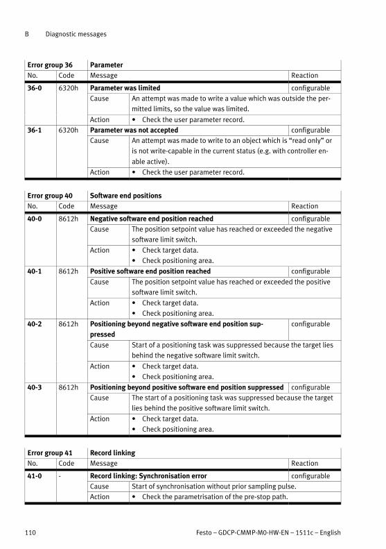
B Diagnostic messages
110 Festo – GDCP-CMMP-M0-HW-EN – 1511c – English
Error group 36 Parameter
No. Code Message Reaction
36-0 6320h Parameter was limited configurable
Cause An attempt was made to write a value which was outside the per
mitted limits, so the value was limited.
Action � Check the user parameter record.
36-1 6320h Parameter was not accepted configurable
Cause An attempt was made to write to an object which is “read only” or
is not write-capable in the current status (e.g. with controller en
able active).
Action � Check the user parameter record.
Error group 40 Software end positions
No. Code Message Reaction
40-0 8612h Negative software end position reached configurable
Cause The position setpoint value has reached or exceeded the negative
software limit switch.
Action � Check target data.
� Check positioning area.
40-1 8612h Positive software end position reached configurable
Cause The position setpoint value has reached or exceeded the positive
software limit switch.
Action � Check target data.
� Check positioning area.
40-2 8612h Positioning beyond negative software end position sup
pressed
configurable
Cause Start of a positioning task was suppressed because the target lies
behind the negative software limit switch.
Action � Check target data.
� Check positioning area.
40-3 8612h Positioning beyond positive software end position suppressed configurable
Cause The start of a positioning task was suppressed because the target
lies behind the positive software limit switch.
Action � Check target data.
� Check positioning area.
Error group 41 Record linking
No. Code Message Reaction
41-0 - Record linking: Synchronisation error configurable
Cause Start of synchronisation without prior sampling pulse.
Action � Check the parametrisation of the pre-stop path.
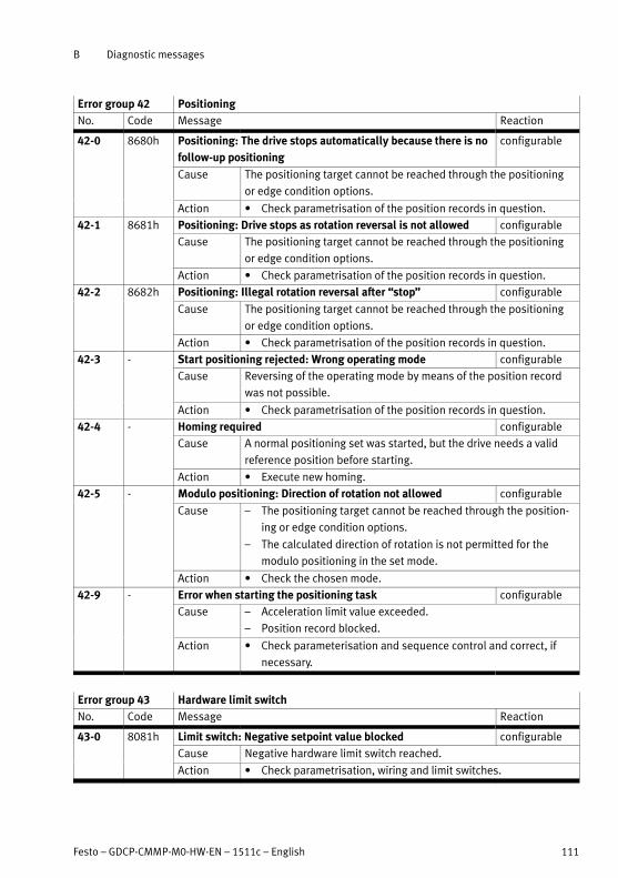
B Diagnostic messages
Festo – GDCP-CMMP-M0-HW-EN – 1511c – English 111
Error group 42 Positioning
No. Code Message Reaction
42-0 8680h Positioning: The drive stops automatically because there is no
follow-up positioning
configurable
Cause The positioning target cannot be reached through the positioning
or edge condition options.
Action � Check parametrisation of the position records in question.
42-1 8681h Positioning: Drive stops as rotation reversal is not allowed configurable
Cause The positioning target cannot be reached through the positioning
or edge condition options.
Action � Check parametrisation of the position records in question.
42-2 8682h Positioning: Illegal rotation reversal after “stop” configurable
Cause The positioning target cannot be reached through the positioning
or edge condition options.
Action � Check parametrisation of the position records in question.
42-3 - Start positioning rejected: Wrong operating mode configurable
Cause Reversing of the operating mode by means of the position record
was not possible.
Action � Check parametrisation of the position records in question.
42-4 - Homing required configurable
Cause A normal positioning set was started, but the drive needs a valid
reference position before starting.
Action � Execute new homing.
42-5 - Modulo positioning: Direction of rotation not allowed configurable
Cause – The positioning target cannot be reached through the position
ing or edge condition options.
– The calculated direction of rotation is not permitted for the
modulo positioning in the set mode.
Action � Check the chosen mode.
42-9 - Error when starting the positioning task configurable
Cause – Acceleration limit value exceeded.
– Position record blocked.
Action � Check parameterisation and sequence control and correct, if
necessary.
Error group 43 Hardware limit switch
No. Code Message Reaction
43-0 8081h Limit switch: Negative setpoint value blocked configurable
Cause Negative hardware limit switch reached.
Action � Check parametrisation, wiring and limit switches.

B Diagnostic messages
112 Festo – GDCP-CMMP-M0-HW-EN – 1511c – English
Error group 43 Hardware limit switch
No. ReactionMessageCode
43-1 8082h Limit switch: Positive setpoint value blocked configurable
Cause Positive hardware limit switch reached.
Action � Check parametrisation, wiring and limit switches.
43-2 8083h Limit switch: Positioning suppressed configurable
Cause – The drive has left the intended range of motion.
– Technical defect in the system?
Action � Check the intended range of motion.
Error group 44 Cam disks
No. Code Message Reaction
44-0 - Fault in the cam disc tables configurable
Cause The cam disc to be started is not available.
Action � Check transferred cam disc no.
� Correct parametrisation.
� Correct programming.
44-1 - Cam disc: General error homing configurable
Cause – Start of a cam disc, but the drive is not yet referenced.
Action � Carry out a homing run.
Cause – Start of homing with active cam disc.
Action � Deactivate cam disk. Then restart cam disc, if necessary.
Error group 47 Setting up
No. Code Message Reaction
47-0 - Setting-up timeout configurable
Cause The speed required for setting-up was not fallen below in time.
Action Check processing of the request on the control side.
Error group 48 Homing required
No. Code Message Reaction
48-0 - Homing required QStop
Cause An attempt is being made to switch to the speed control or torque
control operating mode or to issue the controller enable in one of
these operating modes, although the drive requires a valid refer
ence position for this.
Action � Carry out a homing run.

B Diagnostic messages
Festo – GDCP-CMMP-M0-HW-EN – 1511c – English 113
Error group 49 DCO file
No. Code Message Reaction
49-1 - DCO file: Wrong password QStop
Cause – Parameter file with incorrect password should be loaded.
– Old parameter file (still no password entered) should be loaded
in protected motor controller.
Action Loading only possible with valid password.
Error group 50 CAN communication
No. Code Message Reaction
50-0 - Too many synchronous PDOs configurable
Cause More PDOs have been activated than can be processed in the un
derlying SYNC interval.
This message also appears if only one PDO is to be transmitted
synchronously, but a high number of other PDOs with a different
transmission type have been activated.
Action � Check the activation of PDOs.
If the configuration is appropriate, the warning can be suppressed
using error management.
� Extend the synchronisation interval.
50-1 - SDO errors have occurred configurable
Cause An SDO transfer has caused an SDO abort.
– Data exceeds the range of values.
– Access to non-existent object.
Action � Check the command sent.
Error group 51 Safety module/function
No. Code Message Reaction
51-0 8091h No / unknown safety module or driver supply faulty PSoff
Cause Internal voltage error of the STO circuit.
Action � Protection circuit defective. No action possible, please contact
Festo. If possible, replace with another motor controller.
Error group 52 Safety function
No. Code Message Reaction
52-1 8099h Safety function: Discrepancy time overrun PSoff
Cause – Control ports STO-A and STO-B are not actuated simultaneously.
Action � Check discrepancy time.
Cause – Control ports STO-A and STO-B are not wired in the same way.
Action � Check discrepancy time.
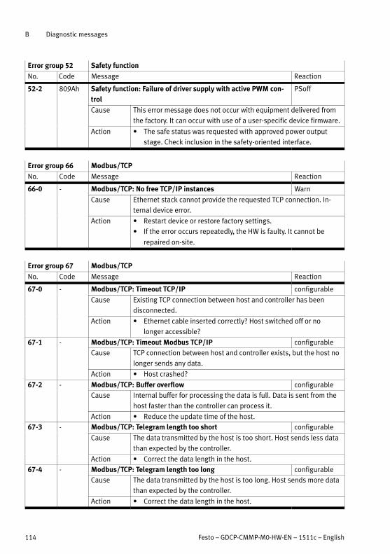
B Diagnostic messages
114 Festo – GDCP-CMMP-M0-HW-EN – 1511c – English
Error group 52 Safety function
No. ReactionMessageCode
52-2 809Ah Safety function: Failure of driver supply with active PWM con
trol
PSoff
Cause This error message does not occur with equipment delivered from
the factory. It can occur with use of a user-specific device firmware.
Action � The safe status was requested with approved power output
stage. Check inclusion in the safety-oriented interface.
Error group 66 Modbus/TCP
No. Code Message Reaction
66-0 - Modbus/TCP: No free TCP/IP instances Warn
Cause Ethernet stack cannot provide the requested TCP connection. In
ternal device error.
Action � Restart device or restore factory settings.
� If the error occurs repeatedly, the HW is faulty. It cannot be
repaired on-site.
Error group 67 Modbus/TCP
No. Code Message Reaction
67-0 - Modbus/TCP: Timeout TCP/IP configurable
Cause Existing TCP connection between host and controller has been
disconnected.
Action � Ethernet cable inserted correctly? Host switched off or no
longer accessible?
67-1 - Modbus/TCP: Timeout Modbus TCP/IP configurable
Cause TCP connection between host and controller exists, but the host no
longer sends any data.
Action � Host crashed?
67-2 - Modbus/TCP: Buffer overflow configurable
Cause Internal buffer for processing the data is full. Data is sent from the
host faster than the controller can process it.
Action � Reduce the update time of the host.
67-3 - Modbus/TCP: Telegram length too short configurable
Cause The data transmitted by the host is too short. Host sends less data
than expected by the controller.
Action � Correct the data length in the host.
67-4 - Modbus/TCP: Telegram length too long configurable
Cause The data transmitted by the host is too long. Host sends more data
than expected by the controller.
Action � Correct the data length in the host.

B Diagnostic messages
Festo – GDCP-CMMP-M0-HW-EN – 1511c – English 115
Error group 70 FHPP protocol
No. Code Message Reaction
70-1 - FHPP: Mathematical error configurable
Cause Overrun/underrun or division by zero during calculation of cyclic
data.
Action � Check the cyclic data.
� Check the factor group.
70-2 - FHPP: Factor group invalid configurable
Cause Calculation of the factor group leads to invalid values.
Action � Check the factor group.
70-3 - FHPP: Invalid operating mode change configurable
Cause Changing from the current to the desired operating mode is not
permitted.
– Error occurs when the OPM bits in the status S5 ‘Reaction to
fault’ or S4 ‘Operation enabled’ are changed.
– Exception: In the status SA1 ‘Ready’, the change between ‘Re
cord select’ and ‘Direct Mode’ is permissible.
Action � Check your application. It may be that not every change is per
missible.
Error group 71 FHPP protocol
No. Code Message Reaction
71-1 - FHPP: Wrong receive telegram length configurable
Cause Too little data is being transmitted by the control system (data
length too short).
Action � Check the data length parameterised in the control system for
the controller’s receive telegram.
� Check the configured data length in the FHPP+ Editor of the FCT.
71-2 - FHPP: Wrong response telegram length configurable
Cause Too much data is to be transmitted from the motor controller to the
control system (data length too great).
Action � Check the data length parameterised in the control system for
the controller’s receive telegram.
� Check the configured data length in the FHPP+ Editor of the FCT.
Error group 80 IRQ overflow
No. Code Message Reaction
80-0 F080h Current regulator IRQ overflow PSoff
Cause The process data could not be calculated in the set current/velo
city/position interpolator cycle.
Action � Please contact Technical Support.

B Diagnostic messages
116 Festo – GDCP-CMMP-M0-HW-EN – 1511c – English
Error group 80 IRQ overflow
No. ReactionMessageCode
80-1 F081h Speed regulator IRQ overflow PSoff
Cause The process data could not be calculated in the set current/velo
city/position interpolator cycle.
Action � Please contact Technical Support.
80-2 F082h Overflow position controller IRQ PSoff
Cause The process data could not be calculated in the set current/velo
city/position interpolator cycle.
Action � Please contact Technical Support.
80-3 F083h Interpolator IRQ overflow PSoff
Cause The process data could not be calculated in the set current/velo
city/position interpolator cycle.
Action � Please contact Technical Support.
Error group 81 IRQ overflow
No. Code Message Reaction
81-4 F084h Low-Level IRQ overflow PSoff
Cause The process data could not be calculated in the set current/velo
city/position interpolator cycle.
Action � Please contact Technical Support.
81-5 F085h MDC IRQ overflow PSoff
Cause The process data could not be calculated in the set current/velo
city/position interpolator cycle.
Action � Please contact Technical Support.
Error group 82 Internal sequencing control
No. Code Message Reaction
82-0 - Internal sequencing control: Process cancelled configurable
Cause IRQ4 overflow (10 ms low-level IRQ).
Action � Internal process control: Process was interrupted.
� Only for information - no measures required.
82-1 - Multiple-started CO write access configurable
Cause Parameters in cyclical and acyclical operation are used concurrently.
Action � Only one parameterisation interface can be used (USB or
Ethernet).

B Diagnostic messages
Festo – GDCP-CMMP-M0-HW-EN – 1511c – English 117
Error group 84 Condition for controller enable
No. Code Message Reaction
84-0 - Conditions for controller enable not fulfilled Warn
Cause One or more conditions for controller enable are not fulfilled.
These include:
– DIN4 (output stage enable) is off.
– DIN5 (controller enable) is off.
– Intermediate circuit not yet loaded.
– Encoder is not yet ready for operation.
– Angle encoder identification is still active.
– Automatic current regulator identification is still active.
– Encoder data is invalid.
– Status change of the safety function not yet completed.
– Firmware or DCO download via Ethernet (TFTP) active.
– DCO download onto memory card still active.
– Firmware download via Ethernet active.
Action � Check status of digital inputs.
� Check encoder cables.
� Wait for automatic identification.
� Wait for completion of the firmware or DCO download.
Error group 90 Internal error
No. Code Message Reaction
90-0 5080h External RAM not recognized PSoff
Cause External SRAM not detected / not sufficient.
Hardware error (SRAM component or board is defective).
Action � Please contact Technical Support.
90-2 5080h Error at FPGA boot-up PSoff
Cause The FPGA (hardware) cannot be booted. The FPGA is booted seri
ally when the device is started, but in this case it could not be
loaded with data or it reported a checksum error.
Action � Switch on the device again (24 V). If the error occurs again, the
hardware is faulty.
90-3 5080h Error at SD-ADU start PSoff
Cause SD-ADUs (hardware) cannot be started. One or more SD-ADUs are
not supplying any serial data.
Action � Switch on the device again (24 V). If the error occurs again, the
hardware is faulty.
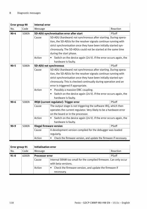
B Diagnostic messages
118 Festo – GDCP-CMMP-M0-HW-EN – 1511c – English
Error group 90 Internal error
No. ReactionMessageCode
90-4 5080h SD-ADU synchronisation error after start PSoff
Cause SD-ADU (hardware) not synchronous after starting. During opera
tion, the SD-ADUs for the resolver signals continue running with
strict synchronisation once they have been initially started syn
chronously. The SD-ADUs could not be started at the same time
during the start phase.
Action � Switch on the device again (24 V). If the error occurs again, the
hardware is faulty.
90-5 5080h SD-ADU not synchronous PSoff
Cause SD-ADU (hardware) not synchronous after starting. During opera
tion, the SD-ADUs for the resolver signals continue running with
strict synchronisation once they have been initially started syn
chronously. This is checked continually during operation and an
error is triggered if appropriate.
Action � Possibly a massive EMC coupling.
� Switch on the device again (24 V). If the error occurs again, the
hardware is faulty.
90-6 5080h IRQ0 (current regulator): Trigger error PSoff
Cause The output stage is not triggering the software IRQ, which then
operates the current regulator. Very likely to be a hardware error
on the board or in the processor.
Action � Switch on the device again (24 V). If the error occurs again, the
hardware is faulty.
90-9 5080h Illegal firmware version PSoff
Cause A development version compiled for the debugger was loaded
regularly.
Action � Check the firmware version, and update the firmware if necessary.
Error group 91 Initialisation error
No. Code Message Reaction
91-0 6000h Processor error PSoff
Cause Internal SRAM too small for the compiled firmware. Can only occur
with beta versions.
Action � Check the firmware version, and update the firmware if
necessary.

B Diagnostic messages
Festo – GDCP-CMMP-M0-HW-EN – 1511c – English 119
Error group 91 Initialisation error
No. ReactionMessageCode
91-1 - Memory error when copying PSoff
Cause Firmware parts were not copied correctly from the external FLASH
into the internal RAM.
Action � Switch on the device again (24 V). If the error occurs re
peatedly, check the firmware version and update the firmware if
necessary.
91-2 - Error when reading the controller/power section coding PSoff
Cause The ID-EEPROM in the controller or power section could either not
be addressed at all or does not have consistent data.
Action � Switch on the device again (24 V). If the error occurs
repeatedly, the hardware is faulty. No repair possible.
91-3 - Software initialisation error PSoff
Cause One of the following components is missing or could not be
initialised:
a) Shared memory not available or defective.
b) Driver library not available or defective.
Action � Check firmware design, update if necessary.
Error group 92 Bootloader/firmware update
No. Code Message Reaction
92-0 - Error during firmware download PSoff
Cause Error during requested firmware download.
Action � Check firmware file.
� Restart firmware download.
92-1 - Error during bootloader update PSoff
Cause Error during requested bootloader download.
Action � Restart the bootloader download.
� Return device to manufacturer for inspection.

B Diagnostic messages
120 Festo – GDCP-CMMP-M0-HW-EN – 1511c – English
Instructions on actions with the error messages 08-2 … 08-7
Action Notes
� Check
whether
encoder
signals are
faulty.
– Check the wiring, e.g. are one or more phases of the track signals interrupted
or short-circuited?
– Check that installation complies with EMC recommendations (cable screening
on both sides?).
– Only with incremental encoders:
With TTL single-ended signals (HALL signals are always TTL single-ended sig
nals): Check whether there might be an excessive voltage drop on the GND
line; in this case = signal reference.
Check whether there might be an excessive voltage drop on the GND line; in
this case = signal reference.
– Check the level of supply voltage on the encoder. Sufficient? If not, change the
cable diameter (connect unused lines in parallel) or use voltage feedback
(SENSE+ and SENSE-).
� Test with
other
encoders.
– If the error still occurs when the configuration is correct, test with a different
(error-free) encoder (replace the connecting cable as well). If the error still
occurs, there is a fault in the motor controller. Repair by the manufacturer
required.
Tab. B.2 Instructions on error messages 08-2 … 08-7
CMMP-AS-...-M0
Festo – GDCP-CMMP-M0-HW-EN – 1511c – English 121
Index
A
Allocation of the plug connectors 25. . . . . . . . . .
C
CAN bus [X4] 75. . . . . . . . . . . . . . . . . . . . . . . . . . .
Check operating status 58. . . . . . . . . . . . . . . . . .
Commissioning 56. . . . . . . . . . . . . . . . . . . . . . . . .
Communication interfaces 73. . . . . . . . . . . . . . . .
Connecting a PC 57. . . . . . . . . . . . . . . . . . . . . . . .
Connecting the power supply 57. . . . . . . . . . . . .
Connection: CAN bus [X4] 36. . . . . . . . . . . . . . . .
Connection: Encoder [X2B] 33. . . . . . . . . . . . . . .
Connection: I/O communication [X1] 29. . . . . . . .
Connection: Incremental encoder input [X10] 44.
Connection: Incremental encoder output [X11] 45
Connection: Motor [X6] 37. . . . . . . . . . . . . . . . . .
Connection: Resolver [X2A] 32. . . . . . . . . . . . . . .
Connection: Voltage supply [X9] 39. . . . . . . . . . .
D
Device view 15. . . . . . . . . . . . . . . . . . . . . . . . . . .
Documentation 6. . . . . . . . . . . . . . . . . . . . . . . . .
E
Electrical installation 23. . . . . . . . . . . . . . . . . . . .
Emitted interference 51. . . . . . . . . . . . . . . . . . . .
Encoder connection [X2B] 75. . . . . . . . . . . . . . . .
Entire CMMP-AS system 13. . . . . . . . . . . . . . . . . .
ESD 24. . . . . . . . . . . . . . . . . . . . . . . . . . . . . . . . . .
ESD protection 55. . . . . . . . . . . . . . . . . . . . . . . . .
G
General information on EMC 51. . . . . . . . . . . . . .
I
I/O interface [X1] 73. . . . . . . . . . . . . . . . . . . . . . .
Installation clearance 22. . . . . . . . . . . . . . . . . . . .
Installation clearances 19. . . . . . . . . . . . . . . . . . .
Instructions on safe and EMC-compliant
installation 51. . . . . . . . . . . . . . . . . . . . . . . . . .
Intended use 10. . . . . . . . . . . . . . . . . . . . . . . . . .
Intermediate circuit coupling 42. . . . . . . . . . . . . .
M
Manufacturing year 7. . . . . . . . . . . . . . . . . . . . . .
Mechanical installation 19. . . . . . . . . . . . . . . . . .
Mounting clearance 22. . . . . . . . . . . . . . . . . . . . .
O
Operation and display components 61. . . . . . . . .
Overload current and short-circuit monitoring 59
P
PFC 41. . . . . . . . . . . . . . . . . . . . . . . . . . . . . . . . . .
Product identification 6. . . . . . . . . . . . . . . . . . . .
R
Rating plate 6. . . . . . . . . . . . . . . . . . . . . . . . . . . .
Resistance to interference 51. . . . . . . . . . . . . . . .
Resolver connection [X2A] 74. . . . . . . . . . . . . . . .
S
Service functions and diagnostic messages 59. .
T
Technical appendix 65. . . . . . . . . . . . . . . . . . . . . .
Type codes 7. . . . . . . . . . . . . . . . . . . . . . . . . . . . .

Reproduction, distribution or sale of this document or communication of its contents to others without express authorization isprohibited. Offenders will be liable for damages. All rights reserved in the event that a patent, utility model or design patent isregistered.
Copyright:Festo AG & Co. KGPostfach73726 EsslingenGermany
Phone:+49 711 347-0
Fax:+49 711 347-2144
e-mail:[email protected]
Internet:www.festo.com
Original: de


![EtherCAT for motor controllers CMMP−AS · Description EtherCAT CMMP−AS Description 570 924 en 0912NH [749 128] EtherCAT for motor controllers CMMP−AS](https://img.dokumen.tips/doc/110x75/5aedbf437f8b9a45569014dd/ethercat-for-motor-controllers-cmmpas-ethercat-cmmpas-description-570-924.jpg)


![Motor controller CMMP-AS--M3€¦ · 4.3.2 Pin assignment [X1] 31..... 4.3.3 Use analogue inputs as digital ... GDCP-CMMP-M3-HW-EN – 1511c – English 9 1 Safety and requirements](https://img.dokumen.tips/doc/110x75/5f02396f7e708231d4033176/motor-controller-cmmp-as-m3-432-pin-assignment-x1-31-433-use-analogue.jpg)


![EtherCAT para controlador del motor CMMP−AS€¦ · Descripción EtherCAT CMMP−AS Descripción 570 925 es 0912NH [749 129] EtherCAT para controlador del motor CMMP−AS](https://img.dokumen.tips/doc/110x75/5fa23dad1f667a6a431c8387/ethercat-para-controlador-del-motor-cmmpaas-descripcin-ethercat-cmmpaas-descripcin.jpg)


